

Page 1

FormNo.3417-412RevA
TimeCutter
®
SW4200,SW5000,
orSWX5000RidingMower
ModelNo.74788—SerialNo.400000000andUp
ModelNo.74790—SerialNo.402000000andUp
ModelNo.74795—SerialNo.401000000andUp
Registeratwww.T oro.com.
OriginalInstructions(EN)
*3417-412*A
Page 2

WARNING
CALIFORNIA
Proposition65Warning
Thisproductcontainsachemical
orchemicalsknowntotheStateof
Californiatocausecancer,birthdefects,
orreproductiveharm.
Theengineexhaustfromthisproduct
containschemicalsknowntotheStateof
Californiatocausecancer,birthdefects,
orotherreproductiveharm.
ItisaviolationofCaliforniaPublicResourceCode
Section4442or4443touseoroperatetheengineon
anyforest-covered,brush-covered,orgrass-covered
landunlesstheengineisequippedwithaspark
arrester,asdenedinSection4442,maintainedin
effectiveworkingorderortheengineisconstructed,
equipped,andmaintainedforthepreventionofre.
DealertoobtaintheproperHighAltitudeKitand
high-altitudelabelforyourmachine.Tolocate
adealerconvenienttoyou,accessourwebsite
atwww.T oro.comorcontactourT oroCustomer
CareDepartmentatthenumber(s)listedinyour
EmissionControlWarrantyStatement.
Removethekitfromtheengineandrestorethe
enginetoitsoriginalfactorycongurationwhen
runningtheengineunder1500m(5,000ft).Do
notoperateanenginethathasbeenconverted
forhigh-altitudeuseatloweraltitudes;otherwise,
youcouldoverheatanddamagetheengine.
Ifyouareunsurewhetherornotyourmachine
hasbeenconvertedforhigh-altitudeuse,lookfor
thefollowinglabel.
GrossorNetTorque
Thegrossornettorqueofthisenginewaslaboratory
ratedbytheenginemanufacturerinaccordancewith
theSocietyofAutomotiveEngineers(SAE)J1940
orJ2723.Asconguredtomeetsafety,emission,
andoperatingrequirements,theactualenginetorque
onthisclassofmowerwillbesignicantlylower.
Pleaserefertotheenginemanufacturer’sinformation
includedwiththemachine.
WARNING
Removingstandardoriginalequipmentparts
andaccessoriesmayalterthewarranty,
traction,andsafetyofthemachine.Failureto
useoriginalT oropartscouldcauseserious
injuryordeath.Makingunauthorizedchanges
totheengine,fuel,orventingsystem,may
violateregulations.
Replaceallpartsincluding,butnotlimited
to,tires,belts,blades,andfuelsystem
componentswithoriginalToroparts.
decal127-9363
Introduction
Thisrotary-blade,ridinglawnmowerisintendedtobe
usedbyprofessional,hiredoperatorsorresidential
homeowners.Itisdesignedprimarilyforcuttinggrass
onwell-maintainedlawnsonresidentialorcommercial
properties.Itisnotdesignedforcuttingbrushorfor
agriculturaluses.
Readthisinformationcarefullytolearnhowtooperate
andmaintainyourproductproperlyandtoavoid
injuryandproductdamage.Youareresponsiblefor
operatingtheproductproperlyandsafely .
YoumaycontactTorodirectlyatwww.Toro.com
forproductsafetyandoperationtrainingmaterials,
accessoryinformation,helpndingadealer,orto
registeryourproduct.
Gotowww.Toro.comtoviewspecicationsonyour
model.
Important:IfyouareusingamachinewithaToro
engineabove1500m(5,000ft)foracontinuous
period,ensurethattheHighAltitudeKithasbeen
installedsothattheenginemeetsCARB/EP A
emissionregulations.TheHighAltitudeKit
increasesengineperformancewhilepreventing
spark-plugfouling,hardstarting,andincreased
emissions.Onceyouhaveinstalledthekit,attach
thehigh-altitudelabelnexttotheserialdecalon
themachine.ContactanyAuthorizedToroService
©2017—TheToro®Company
8111LyndaleAvenueSouth
Bloomington,MN55420
FortheOperator’sManual,thecompletewarranty
details,ortoregisteryourproduct,usetheQR
codeorvisitwww.Toro.com.Y oumayalsocallus
at1-888-384-9939torequestawrittencopyofthe
productwarranty.
Wheneveryouneedservice,genuineToroparts,or
additionalinformation,contactanAuthorizedService
DealerorToroCustomerServiceandhavethemodel
andserialnumbersofyourproductready.Figure1
identiesthelocationofthemodelandserialnumbers
ontheproduct.Writethenumbersinthespace
provided.
Contactusatwww.Toro.com.
2
PrintedintheUSA
AllRightsReserved
Page 3
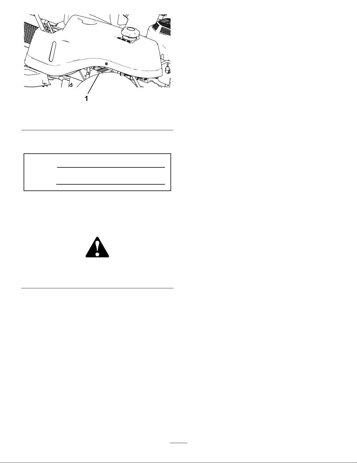
Figure1
1.Modelandserialnumberplate
Writetheproductmodelandserialnumbersinthe
spacebelow:
ModelNo.
SerialNo.
Thismanualidentiespotentialhazardsandhas
safetymessagesidentiedbythesafety-alertsymbol
(Figure2),whichsignalsahazardthatmaycause
seriousinjuryordeathifyoudonotfollowthe
recommendedprecautions.
Figure2
Safety-alertsymbol
Thismanualuses2wordstohighlightinformation.
Importantcallsattentiontospecialmechanical
informationandNoteemphasizesgeneralinformation
worthyofspecialattention.
Contents
Safety.......................................................................4
GeneralSafety...................................................4
SlopeIndicator...................................................5
SafetyandInstructionalDecals..........................6
ProductOverview...................................................13
Controls...........................................................13
BeforeOperation.................................................14
BeforeOperationSafety...................................14
AddingFuel......................................................15
g230912
g000502
PerformingDailyMaintenance..........................16
BreakinginaNewMachine..............................16
UsingtheSafety-InterlockSystem....................16
PositioningtheSeat..........................................17
PositioningtheSteeringWheel.........................18
DuringOperation.................................................18
DuringOperationSafety...................................18
OperatingtheSmartPark
™
Parking
Brake............................................................20
EngagingtheBlade-ControlSwitch
(PTO)............................................................20
DisengagingtheBlade-ControlSwitch
(PTO)............................................................21
OperatingtheThrottle.......................................21
OperatingtheChoke.........................................21
StartingtheEngine...........................................22
ShuttingOfftheEngine.....................................22
DrivingtheMachine..........................................22
MowinginReverse...........................................23
UsingtheSideDischarge.................................23
AdjustingtheHeightofCut...............................24
AdjustingtheAnti-ScalpRollers........................24
OperatingTips.................................................25
AfterOperation....................................................26
AfterOperationSafety......................................26
PushingtheMachinebyHand..........................26
TransportingtheMachine.................................27
Maintenance...........................................................29
RecommendedMaintenanceSchedule(s)...........29
Pre-MaintenanceProcedures..............................30
MaintenanceSafety..........................................30
RaisingtheSeat...............................................30
RaisingtheFrontoftheMachine.......................30
Lubrication..........................................................31
GreasingtheBearings......................................31
EngineMaintenance...........................................31
EngineSafety...................................................31
ServicingtheAirCleaner..................................31
ServicingtheEngineOil....................................33
ServicingtheSparkPlug...................................35
CleaningtheCoolingSystem............................36
FuelSystemMaintenance...................................37
ReplacingtheIn-LineFuelFilter.......................37
ElectricalSystemMaintenance...........................38
ElectricalSystemSafety...................................38
ServicingtheBattery.........................................38
ServicingtheFuses..........................................39
3
Page 4

DriveSystemMaintenance..................................40
CheckingtheTirePressure...............................40
ReleasingtheElectricBrake.............................40
BeltMaintenance................................................41
ReplacingtheMower-DeckBelt........................41
MowerMaintenance.............................................42
ServicingtheCuttingBlades.............................42
LevelingtheMowerDeck..................................45
RemovingtheMowerDeck...............................47
InstallingtheMowerDeck.................................48
ReplacingtheGrassDeector..........................48
Cleaning..............................................................49
CleaningundertheFrontoftheMachine...........49
WashingtheUndersideoftheMower
Deck..............................................................49
DisposingofWaste...........................................49
Storage...................................................................50
StorageSafety..................................................50
CleaningandStorage.......................................50
StoringtheBattery............................................51
Troubleshooting......................................................52
Schematics.............................................................54
Safety
ThefollowinginstructionsarefromANSIstandard
B71.4-2012.
GeneralSafety
Thisproductiscapableofamputatinghandsand
feetandofthrowingobjects.Alwaysfollowallsafety
instructionstoavoidseriouspersonalinjury.
Usingthisproductforpurposesotherthanitsintended
usecouldprovedangeroustoyouandbystanders.
•Donotoperatethemachineneardrop-offs,
ditches,embankments,water,orotherhazards,or
onslopesgreaterthan15degrees.
•Readandunderstandthecontentsofthis
Operator’sManualbeforestartingtheengine.
•Donotputyourhandsorfeetnearmoving
componentsofthemachine.
•Donotoperatethemachinewithoutallguards
andothersafetyprotectivedevicesinplaceand
workingonthemachine.
•Keepchildrenandbystandersoutoftheoperating
area.Neverallowchildrentooperatethemachine.
•Stopthemachineandshutofftheenginebefore
servicing,fueling,oruncloggingthemachine.
Improperlyusingormaintainingthismachinecan
resultininjury.Toreducethepotentialforinjury,
complywiththesesafetyinstructionsandalwayspay
attentiontothesafety-alertsymbol,whichmeans
Caution,Warning,orDanger—personalsafety
instruction.Failuretocomplywiththeseinstructions
mayresultinpersonalinjuryordeath.
Youcanndadditionalsafetyinformationwhere
neededthroughoutthismanual.
4
Page 5
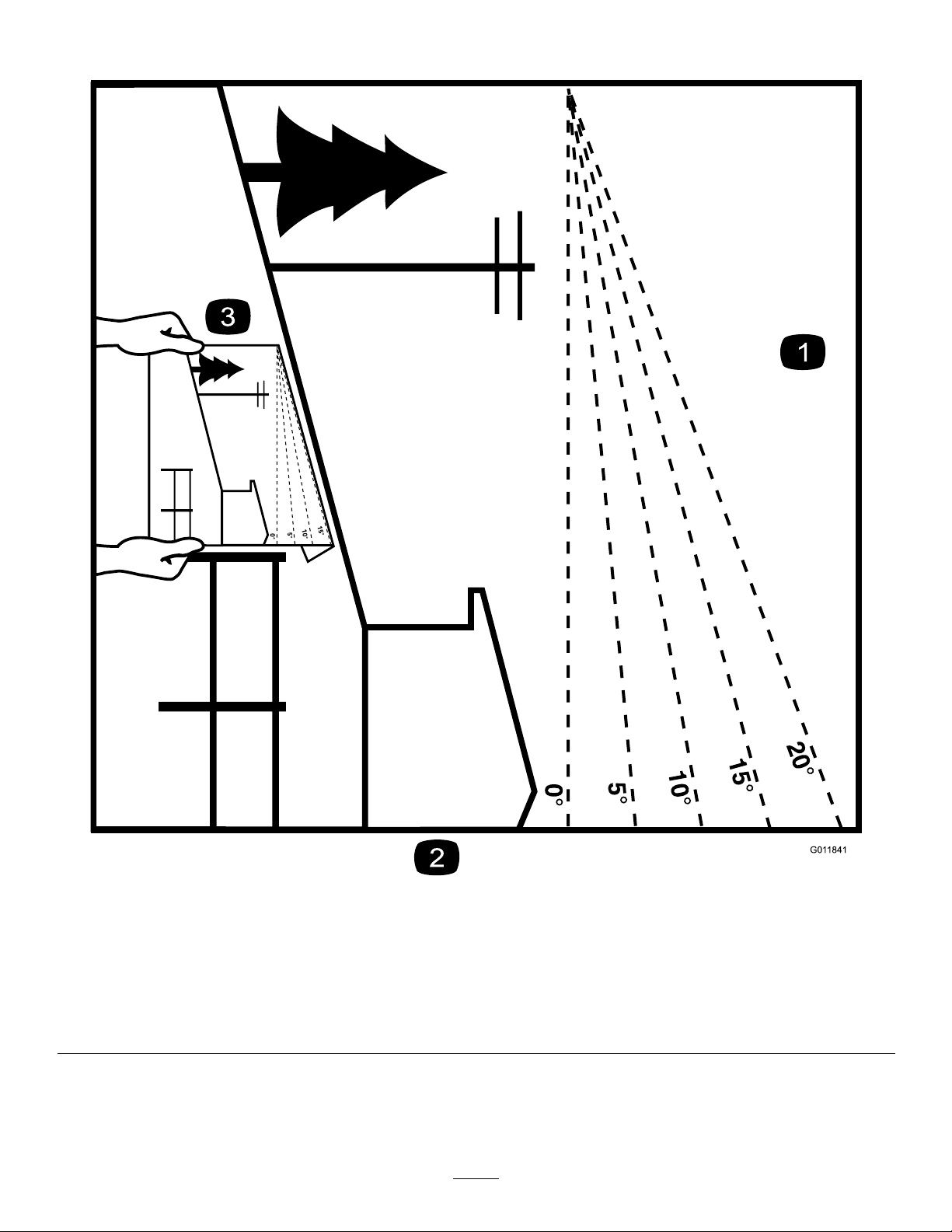
SlopeIndicator
Figure4
Thispagemaybecopiedforpersonaluse.
1.Themaximumslopeyoucanoperatethemachineonis15degrees.Usetheslopecharttodeterminethedegreeofslopeof
hillsbeforeoperating.Donotoperatethismachineonaslopegreaterthan15degrees.Foldalongtheappropriateline
tomatchtherecommendedslope.
2.Alignthisedgewithaverticalsurface,atree,building,fencepole,etc.
3.Exampleofhowtocompareslopewithfoldededge
5
g011841
Page 6
SafetyandInstructionalDecals
Safetydecalsandinstructionsareeasilyvisibletotheoperatorandarelocatednearanyarea
ofpotentialdanger.Replaceanydecalthatisdamagedormissing.
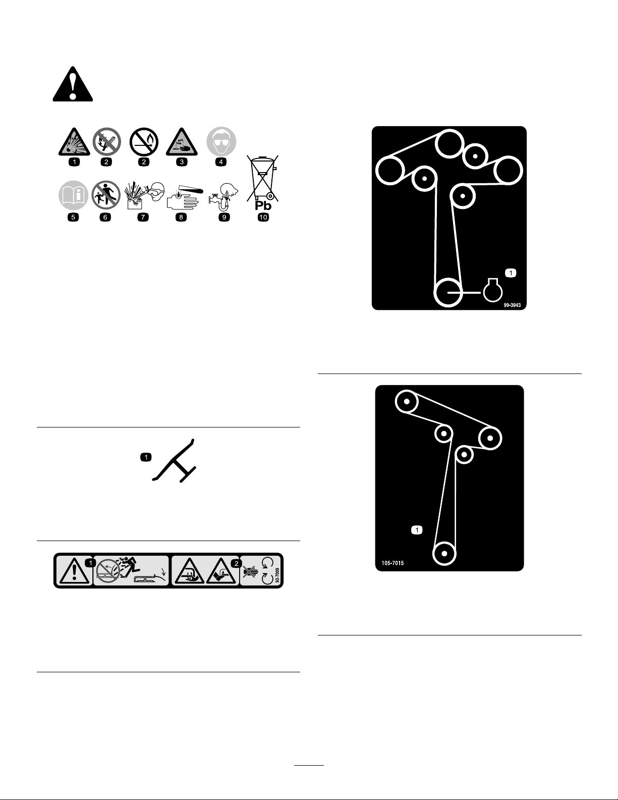
BatterySymbols
Someorallofthesesymbolsareonyourbattery .
decalbatterysymbols
1.Explosionhazard
2.Nore,opename,or
smoking
3.Causticliquid/chemical
burnhazard
4.Weareyeprotection.9.Flusheyesimmediately
5.ReadtheOperator's
Manual.
6.Keepbystandersasafe
distanceawayfromthe
battery.
7.Weareyeprotection;
explosivegasescan
causeblindnessandother
injuries.
8.Batteryacidcancause
blindnessorsevereburns.
withwaterandgetmedical
helpfast.
10.Containslead;donot
discard
Manufacturer'sMark
1.Indicatesthebladeisidentiedasapartfromtheoriginal
machinemanufacturer.
decal99-3943
99-3943
ForModelswith127cm(50inch)Decks
1.Engine
decaloemmarkt
93-7009
1.Warning—donotoperatethemowerwiththedeectorup
orremoved;keepthedeectorinplace.
2.Cutting/dismembermenthazardofhandorfoot,mower
blade—stayawayfrommovingparts.
decal105-7015
decal93-7009
1.Beltrouting
ForModelswith107cm(42-inch)Decks
105-7015
6
Page 7
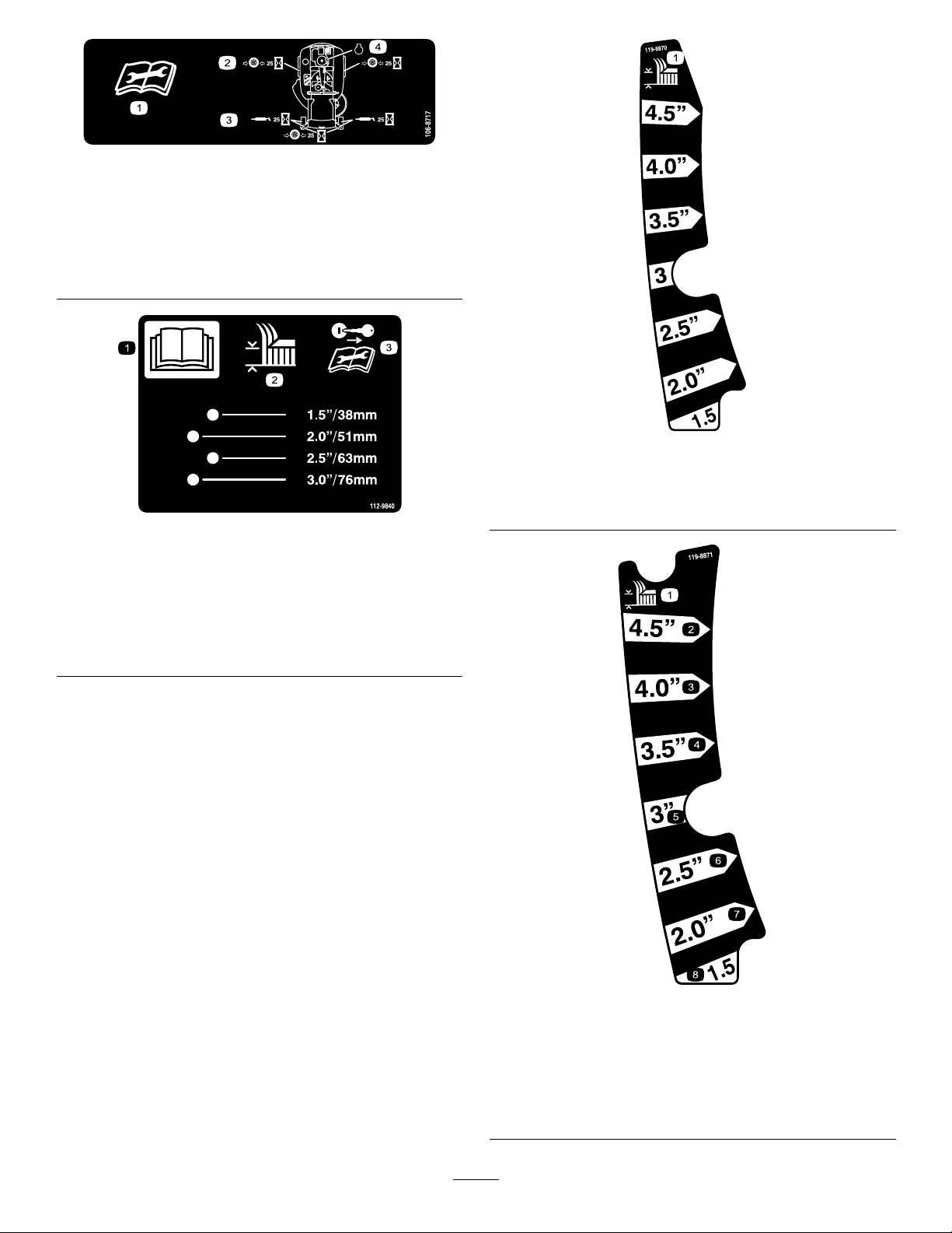
106-8717
1.Readtheinstructionsbeforeservicingorperforming
maintenance.
2.Checktirepressureevery25operatinghours.
3.Greaseevery25operatinghours.
4.Engine
decal106-8717
decal119-8870
119-8870
ForModelswith127cm(50inch)Decks
ForModelswith127cm(50inch)Decks
1.ReadtheOperator's
Manual.
2.Heightofcut
decal112-9840
1.Height-of-cut
112-9840
3.Removethekeyandread
theinstructionsbefore
servicingorperforming
maintenance.
ForModelswith107cm(42inch)MowerDecks
1.Heightofcut
2.4-1/2inches6.2-1/2inches
3.4inches7.2inches
4.3-1/2inches8.1-1/2inches
7
decal119-8871
119-8871
5.3inches
Page 8
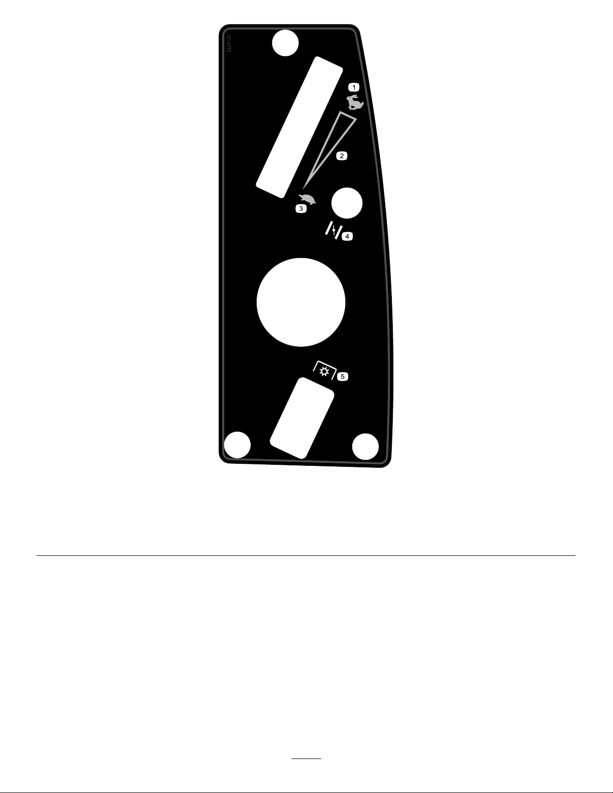
121-0772
ForModelswith107cm(42inch)Decks
decal121-0772
1.Fast
4.Choke
2.Continuous-variablesetting5.Powertakeoff(PTO),blade-controlswitch
3.Slow
8
Page 9
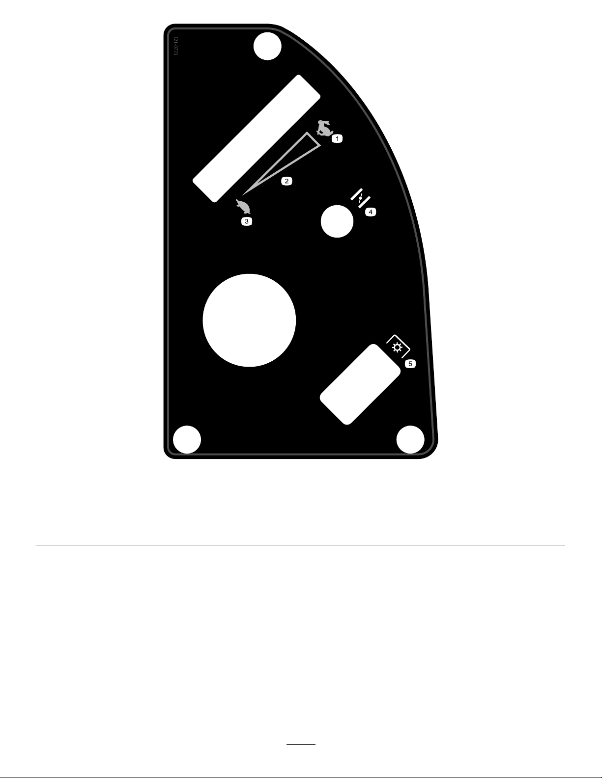
121-0773
ForModelswith127cm(50inch)Decks
decal121-0773
1.Fast
4.Choke
2.Continuous-variablesetting5.Powertakeoff(PTO),blade-controlswitch
3.Slow
9
Page 10

1.Bypassleverpositionfor
pushingthemachine
121-2989
2.Bypassleverpositionfor
operatingthemachine
decal131-3621b
decal121-2989b
131-3621
1.Crushing/dismembermenthazardofbystanders—keep
bystandersawayfromthemachine;donotstartthe
machinewithbystandersnearby.
1.Oildrain
1.Pedalposition—forward
2.Pedalposition—neutral
decal131-1097
131-1097
131-3664
decal131-3664
ForModelswith127cm(50inch)Decks
1.Bladespinning
2.Reverse
decal131-3620
131-3620
3.Pedalposition—reverse
1.Bladespinning
ForModelswith107cm(42inch)Decks
2.Reverse
3.ReadtheOperator's
Manual.
decal131-3665
131-3665
3.ReadtheOperator's
Manual.
10
Page 11
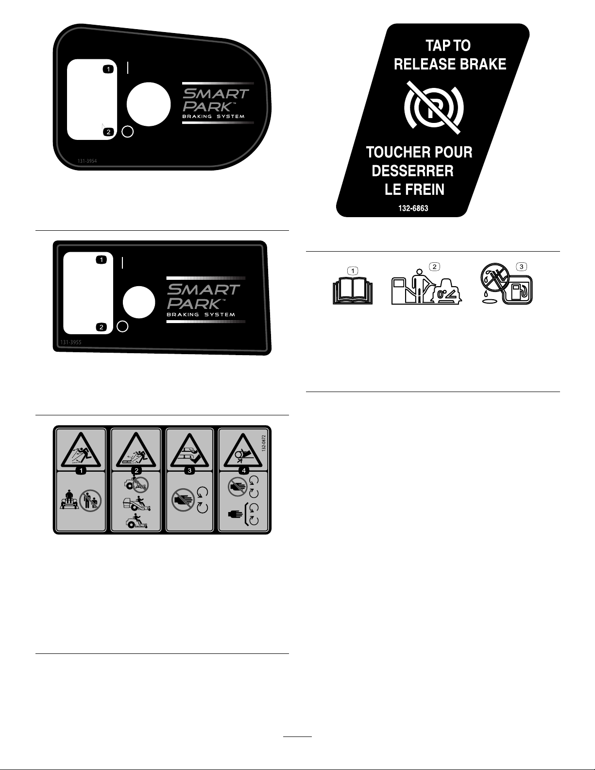
131-3954
ForModelswith127cm(50inch)Decks
decal131-3954
1.On2.Off
131-3955
ForModelswith107cm(42inch)Decks
1.On2.Off
decal132-6863
132-6863
decal138-2456
138-2456
1.ReadtheOperator’s
Manual.
decal131-3955
2.Parkthemachineona
levelsurfacewhenlling
thefueltank.
3.Donotoverllthefuel
tank.
1.Thrownobject
hazard—keepbystanders
awayfromthemachine.
2.Thrownobjecthazard,
raisedbafe—donot
operatethemachinewith
anopendeck;usea
baggerorabafe.
decal132-0872
132-0872
3.Severinghazardofhand
orfoot—keepawayfrom
movingparts.
4.Entanglement
hazard—keepaway
frommovingparts;keep
allguardsandshieldsin
place.
11
Page 12
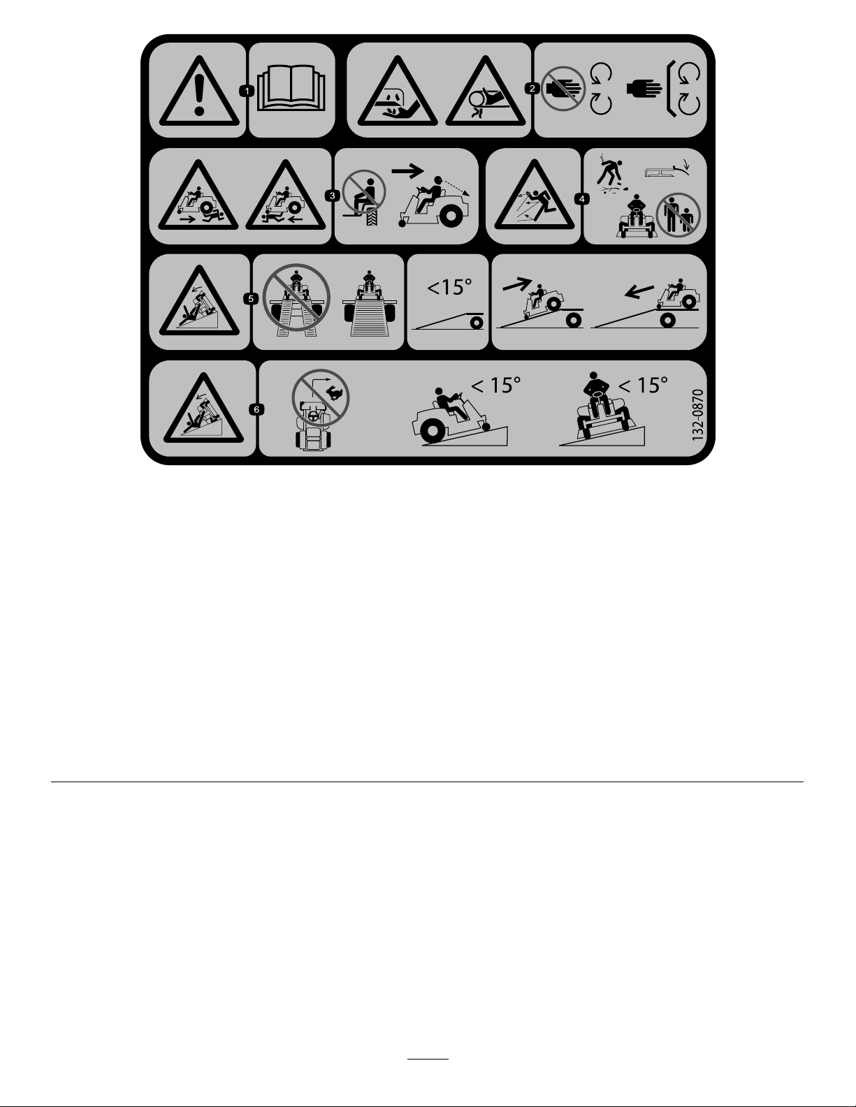
132-0870
Note:Thismachinecomplieswiththeindustrystandardstabilitytestinthestaticlateralandlongitudinaltestswiththemaximum
recommendedslopeindicatedonthedecal.ReviewtheinstructionsforoperatingthemachineonslopesintheOperator’sManualas
wellastheconditionsinwhichyouwouldoperatethemachinetodeterminewhetheryoucanoperatethemachineinthoseconditions
onthatdayandatthatsite.Changesintheterraincanresultinachangeinslopeoperationforthemachine.Ifpossible,keepthe
cuttingunitsloweredtothegroundwhileoperatingthemachineonslopes.Raisingthecuttingunitswhileoperatingonslopescan
causethemachinetobecomeunstable.
decal132-0870
1.Warning—readtheOperator'sManual.
2.Cuttinghazardofhand,mowerblade;
pinchinghazardofhand,belt—keep
handsandfeetawayfrommoving
parts;keepallguardsandshieldsin
place.
3.Bodilyharmhazard—noriders;look
behindyouwhenmowinginreverse.
4.Thrownobjecthazard—keep
bystandersawayfromthemachine;
removedebrisfromtheareabefore
mowing;keepthedeectorshield
down.
5.Ramptippinghazard—whenloading
ontoatrailer,donotusedualramps;
onlyuseasinglerampwideenough
forthemachineandthathasanincline
lessthan15degrees;backupthe
ramp(inreverse)anddriveforwardoff
theramp.
6.Tippinghazardonslopes—donot
makesharp,quickturns;donotuse
slopesgreaterthan15degrees.
12
Page 13
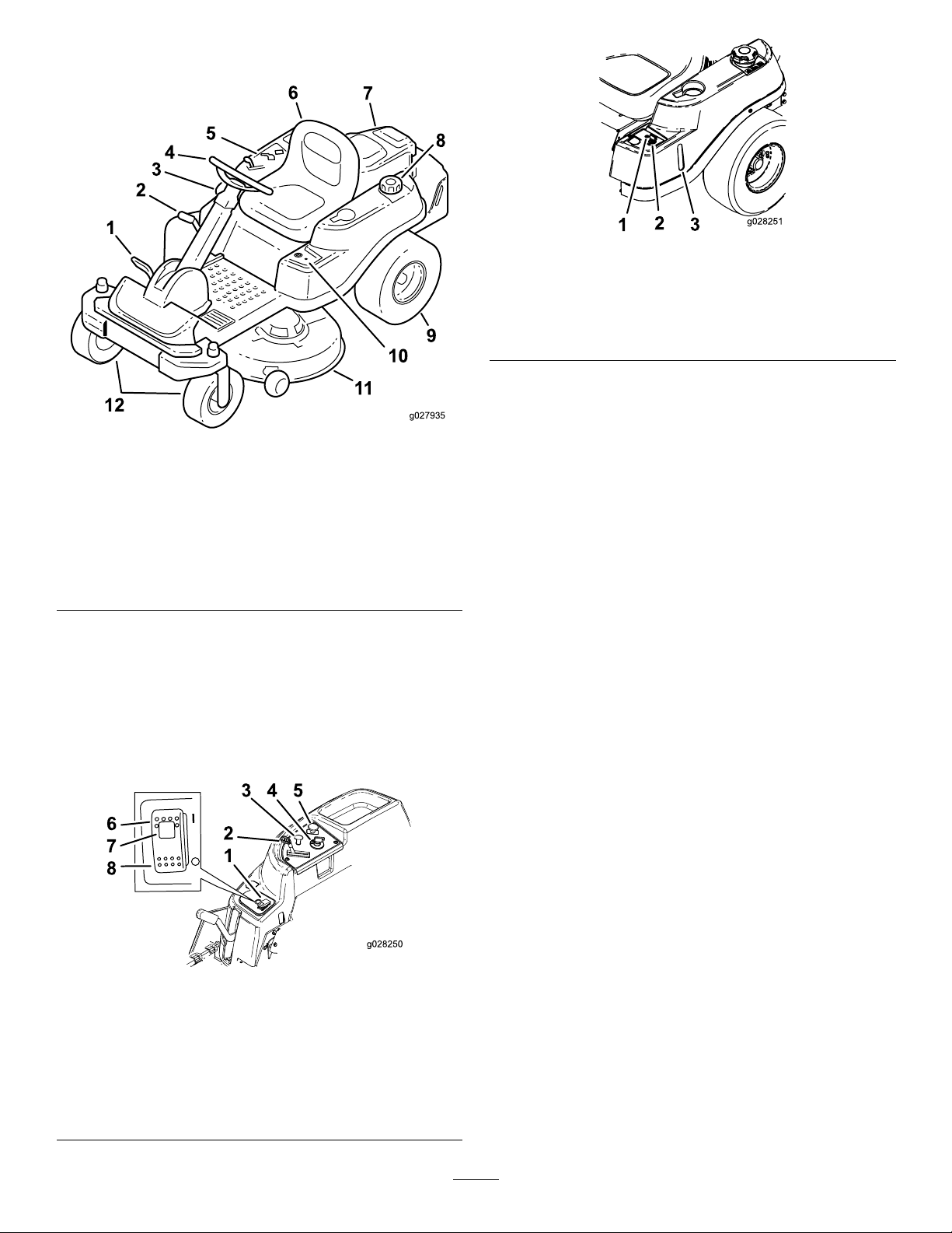
ProductOverview
g028251
Figure7
Figure5
1.Traction-controlpedal7.Engine
2.Height-of-cutlever
3.SmartPark
4.Steeringwheel10.KeyChoice
5.Controlpanel
6.Operatorseat
™
switch
8.Fuel-tankcap
9.Reardrivewheel
®
11.Mowerdeck
12.Frontcasterwheels
Controls
Becomefamiliarwithallthecontrolsbeforeyoustart
theengineandoperatethemachine.
1.Operating–in–Reverse
warninglight
2.KeyChoicekey(bluein
color)
3.Fuel-presencewindow
KeySwitch
g027935
control
Thekeyswitch,usedtostartandshutofftheengine,
has3positions:OFF,RUN,andST ART.Referto
StartingtheEngine(page22).
ThrottleControl
Thethrottlecontrolstheenginespeed,andithasa
continuous-variablesettingfromtheSLOWtoFAST
position(Figure6).
ChokeControl
Usethechokecontroltostartacoldengine.
Blade-ControlSwitch(Power
ControlPanel
1.SmartPark™switch
2.Throttlecontrol
3.Chokecontrol
4.Keyswitch
Figure6
5.Blade-controlswitch
(powertakeoff)
6.Parkingbrake—On
7.Parkingbrakeindicator
light
8.Parkingbrake—Off
Takeoff)
Theblade-controlswitch,representedbya
power-takeoff(PTO)symbol,engagesand
disengagespowertothemowerblades(Figure6).
Fuel-PresenceWindow
Youcanusethefuelwindow,locatedontheleftside
ofthemachine,toverifythepresenceoffuelinthe
tank(Figure7).
g028250
Height-of-CutLever
Usetheheight-of-cutlevertolowerandraisethedeck
fromtheseatedposition.Movingtheleverup(toward
you)raisesthedeckfromthegroundandmovingthe
leverdown(awayfromyou)lowersthedecktoward
theground.Adjusttheheight-of-cutonlywhilethe
machineisnotmoving(Figure20).
13
Page 14

KeyChoice
Thisswitchallowsyoutomowinreversewhenit
isactivated.T oactivateit,turntheswitchtotheON
positionandreleaseitafterthePTOisengaged.T o
deactivateit,disengagethepowertakeoff(PTO)
(Figure7).
®
Switch
Operating-in-ReverseWarning
Light
Operation
Note:Determinetheleftandrightsidesofthe
machinefromthenormaloperatingposition.
BeforeOperation
BeforeOperationSafety
TheOperating-in-Reversewarninglightilluminates
wheneveryouusetheKeyChoicekeytodeactivate
theoperating-in-reverseinterlock.Itisareminderthat
theinterlocksystemisdeactivated.Thelightgoes
outwheneveryoudisengagethePTOorshutoffthe
engine.Whenthelightison,lookbehindyouanduse
extracautionwhenbackingup.
SmartPark
Theparkingbrakeisactivatedelectronically.
Engagetheparkingbrakeby1ofthefollowingactions:
•PressingtheSmartPark
(Figure6).
™
Switch
™
switchtotheONposition
•Theparkingbrakeengagesautomaticallywhen
youleavetheseatandthetractioncontrolpedalis
intheNEUTRALposition.
•Theparkingbrakeautomaticallyengages5to6
secondsaftertheignitionswitchisturnedtothe
OFFposition(ifitisnotalreadyengaged).
Todisengagetheparkingbrake,presstheSmartPark
switchtotheOFFpositionwiththekeyintheRUN
position.
Attachments/Accessories
GeneralSafety
•Neverallowchildrenoruntrainedpeopleto
operateorservicethemachine.Localregulations
mayrestricttheageoftheoperator.Theowner
isresponsiblefortrainingalloperatorsand
mechanics.
•Becomefamiliarwiththesafeoperationofthe
equipment,operatorcontrols,andsafetysigns.
•Knowhowtostopthemachineandshutoffthe
enginequickly.
•Checkthatoperator-presencecontrols,safety
switches,andshieldsareattachedandfunctioning
properly.Donotoperatethemachineunlessthey
arefunctioningproperly.
•Beforemowing,alwaysinspectthemachineto
ensurethattheblades,bladebolts,andcutting
assembliesareingoodworkingcondition.
Replacewornordamagedbladesandboltsinsets
topreservebalance.
•Inspecttheareawhereyouwillusethemachine
andremoveallobjectsthatthemachinecould
throw.
•Evaluatetheterraintodeterminetheappropriate
equipmentandanyattachmentsoraccessories
requiredtooperatethemachineproperlyand
safely.
AselectionofToroapprovedattachmentsand
accessoriesisavailableforusewiththemachineto
enhanceandexpanditscapabilities.Contactyour
AuthorizedServiceDealerorDistributororgoto
www.T oro.comforalistofallapprovedattachments
andaccessories.
Tobestprotectyourinvestmentandmaintainoptimal
performanceofyourToroequipment,countonT oro
genuineparts.Whenitcomestoreliability,T oro
deliversreplacementpartsdesignedtotheexact
engineeringspecicationofourequipment.Forpeace
ofmind,insistonTorogenuineparts.
FuelSafety
•Toavoidpersonalinjuryorpropertydamage,use
extremecareinhandlingfuel.Fuelvaporsare
ammableandexplosive.
•Extinguishallcigarettes,cigars,pipes,andother
sourcesofignition.
•Useonlyanapprovedfuelcontainer.
•Donotremovethefuelcaporaddfueltothefuel
tankwhiletheengineisrunningorwhilehot.
•Donotrefuelthemachineindoors.
•Donotstorethemachineorfuelcontainerwhere
thereisanopename,spark,orpilotlight,such
asonawaterheateroronotherappliances.
•Donotllcontainersinsideavehicleoronatruck
ortrailerbedwithaplasticliner.Alwaysplace
14
Page 15

containersontheground,awayfromyourvehicle
beforelling.
•Removetheequipmentfromthetruckortrailer
andrefuelitwhileitisontheground.Ifthisisnot
possible,thenrefuelfromaportablecontainer
ratherthanafuel-dispensernozzle.
•Donotoperatethemachinewithouttheentire
exhaustsysteminplaceandinproperworking
condition.
•Keepthefuel-dispensernozzleincontactwith
therimofthefueltankorcontaineropeningat
alltimesuntilfuelingiscomplete.Donotusea
nozzlelock-opendevice.
•Ifyouspillfuelonyourclothing,changeyour
clothingimmediately.Wipeupanyfuelthatspills.
•Neveroverllthefueltank.Replacethefuelcap
andtightenitsecurely.
•Storefuelinanapprovedcontainerandkeepit
outofthereachofchildren.Neverbuymorethan
a30-daysupplyoffuel.
•Donotllthefueltankcompletelyfull.Addfuelto
thefueltankuntilthelevelis6to13mm(1/4to
1/2inch)belowthebottomofthellerneck.This
emptyspaceinthetankallowsfueltoexpand.
–Avoidprolongedbreathingofvapors.
–Keepyourfaceawayfromthenozzleandfuel
tankopening.
–Avoidcontactwithskin;washoffspillswith
soapandwater.
UsingStabilizer/Conditioner
Useafuelstabilizer/conditionerinthemachineto
providethefollowingbenets:
•Keepsfuelfreshduringstorageof90daysorless
(drainthefueltankwhenstoringthemachinefor
morethan90days)
•Cleanstheenginewhileitruns
•Eliminatesgum-likevarnishbuildupinthefuel
system,whichcauseshardstarting
Important:Donotusefueladditives
containingmethanolorethanol.
Addthecorrectamountoffuelstabilizer/conditioner
tothefuel.
Note:Afuelstabilizer/conditionerismost
effectivewhenmixedwithfreshfuel.T ominimize
thechanceofvarnishdepositsinthefuelsystem,
usefuelstabilizeratalltimes.
FillingtheFuelTank
1.Parkthemachineonalevelsurface.
2.Engagetheparkingbrake.
3.Shutofftheengineandremovethekey.
4.Cleanaroundthefuel-tankcap.
5.Fillthefueltanktothebottomofthellerneck
(Figure8).
AddingFuel
RecommendedFuel
•Forbestresults,useonlyclean,fresh(lessthan
30daysold),unleadedgasolinewithanoctane
ratingof87orhigher((R+M)/2ratingmethod).
•Ethanol:Gasolinewithupto10%ethanol
(gasohol)or15%MTBE(methyltertiarybutyl
ether)byvolumeisacceptable.Ethanoland
MTBEarenotthesame.Gasolinewith15%
ethanol(E15)byvolumeisnotapprovedforuse.
Neverusegasolinethatcontainsmorethan
10%ethanolbyvolume,suchasE15(contains
15%ethanol),E20(contains20%ethanol),orE85
(containsupto85%ethanol).Usingunapproved
gasolinemaycauseperformanceproblemsand/or
enginedamagewhichmaynotbecoveredunder
warranty.
•Donotusegasolinecontainingmethanol.
•Donotstorefueleitherinthefueltankorfuel
containersoverthewinterunlessyouuseafuel
stabilizer.
•Donotaddoiltogasoline.
Note:Donotllthefueltankcompletelyfull.
Theemptyspaceinthetankallowsthefuelto
expand.
15
Page 16

Understandingthe Safety-InterlockSystem
Thesafety-interlocksystemisdesignedforthe
following:
•Topreventtheenginefromstartingunlessthe
tractionpedalisintheNEUTRALposition.
•Toautomaticallyensurethattheparkingbrake
isengagedandthePTOisoffwhenstartingthe
machine.
•Toshutofftheenginewheneverthetractionpedal
isnotintheNEUTRALpositionandyourisefrom
theseat.
•Toautomaticallyengagetheparkingbrakeand
disengagethePTO,whenyouriseoutoftheseat
withthetractionpedalintheNEUTRALposition.
•Toshutofftheenginewhenevertheparkingbrake
isnotengagedandyourisefromtheseat.
Figure8
PerformingDaily Maintenance
Beforestartingthemachineeachday ,performthe
EachUse/DailyprocedureslistedinMaintenance
(page29).
BreakinginaNewMachine
Newenginestaketimetodevelopfullpower.Mower
decksanddrivesystemshavehigherfrictionwhen
new,placingadditionalloadontheengine.Allow
40to50hoursofbreak-intimefornewmachinesto
developfullpowerandbestperformance.
UsingtheSafety-Interlock System
WARNING
Ifthesafety-interlockswitchesare
disconnectedordamaged,themachinecould
operateunexpectedly,causingpersonal
injury.
•Donottamperwiththeinterlockswitches.
•Checktheoperationoftheinterlock
switchesdailyandreplaceanydamaged
switchesbeforeoperatingthemachine.
g027243
TestingtheSafety-Interlock System
1.Sitintheseatwiththeengineoffandensure
thatthePTOswitchisintheOFFposition.
2.TurnthekeyswitchtotheSTARTposition;the
startershouldcrank.Donotstartorshutoffthe
enginepriortostep3.
3.TurnthekeyswitchtotheONpositionandpush
theSmartParkswitchtotheOFFposition.The
brakeshoulddisengageandthebrakelight
shouldturnoff.
4.Withthebrakedisengagedandtractionpedal
intheNEUTRALposition,turnthekeytothe
STARTposition.Thebrakeshouldautomatically
engage,theengineshouldcrank,andthebrake
lightshouldturnon.
5.WiththeengineoffandthekeyintheON
position,engagethePTObypullingupthe
blade-controlswitch;youshouldheartheclutch
engage.
6.Ensurethatthetractionpedalisinneutraland
turnthekeytotheSTARTposition.ThePTO
shoulddisengageandtheengineshouldcrank
andstartwithoutthebladesmoving.
7.Withtheenginerunning,risefromtheseat.The
engineshouldremainrunningandthebrake
lightshouldbeon.
8.Returntotheseatanddisengagetheparking
brakebypushingtheSmartParkswitchtothe
OFFposition.Theengineshouldcontinuetorun.
9.Risefromtheseatagain.Thebrakeshould
automaticallyengageandtheengineshould
continuetorun.
16
Page 17
10.Returntotheseatandengagethebladesby
pullinguptheblade-controlswitch.
11.Risefromtheseat.Thebladesshould
disengageandtheengineshouldcontinueto
run.
12.Returntotheseatandpulluptheblade-control
switch.Thebladesshouldengage.Disengage
thebladesbypushingdowntheblade-control
switch.
13.Pulluptheblade-controlswitchtoengagethe
blades.MovethetractionpedaltotheREVERSE
position.Thebladesshoulddisengage.Move
thetractionpedaltotheNEUTRALposition.
14.Pulluptheblade-controlswitchtoengagethe
blades.TurntheKeyChoiceswitchtotheON
positionandreleaseit.Theoperating-in-reverse
lightshouldilluminate.
15.MovethetractionpedaltotheREVERSEposition.
Thebladesshouldremainengaged.Pushthe
blade-controlswitchintodisengagetheblades.
Theoperating-in-reverselightshouldturnoff.
MovethetractionpedaltotheNEUTRALposition.
PositioningtheSeat
Theseatcanmoveforwardandbackward.Position
theseatwhereyouhavethebestcontrolofthe
machineandaremostcomfortable(Figure9).
16.Ifnotengaged,pushtheSmarkParkswitchto
theONpositionandlightlytapthetractionpedal
toeithertheFORWARDorREVERSEposition.The
brakeshoulddisengageandthebrakelight
shouldturnoff.
Note:Tapthepedal,donotfullyengagethe
pedalasthatcausesthebrakesystemtobind
andnotrelease.
17.Withthebrakereleased,engagethetraction
pedalslightlyandrisefromtheseat.Theengine
shouldshutoff.
18.ReturntotheseatandturnthekeytotheOFF
position.Afterseveralseconds,thebrake
systemshouldengage.
Note:WiththekeyintheOFFposition,the
brakelightdoesnotilluminate.
g188217
Figure9
17
Page 18

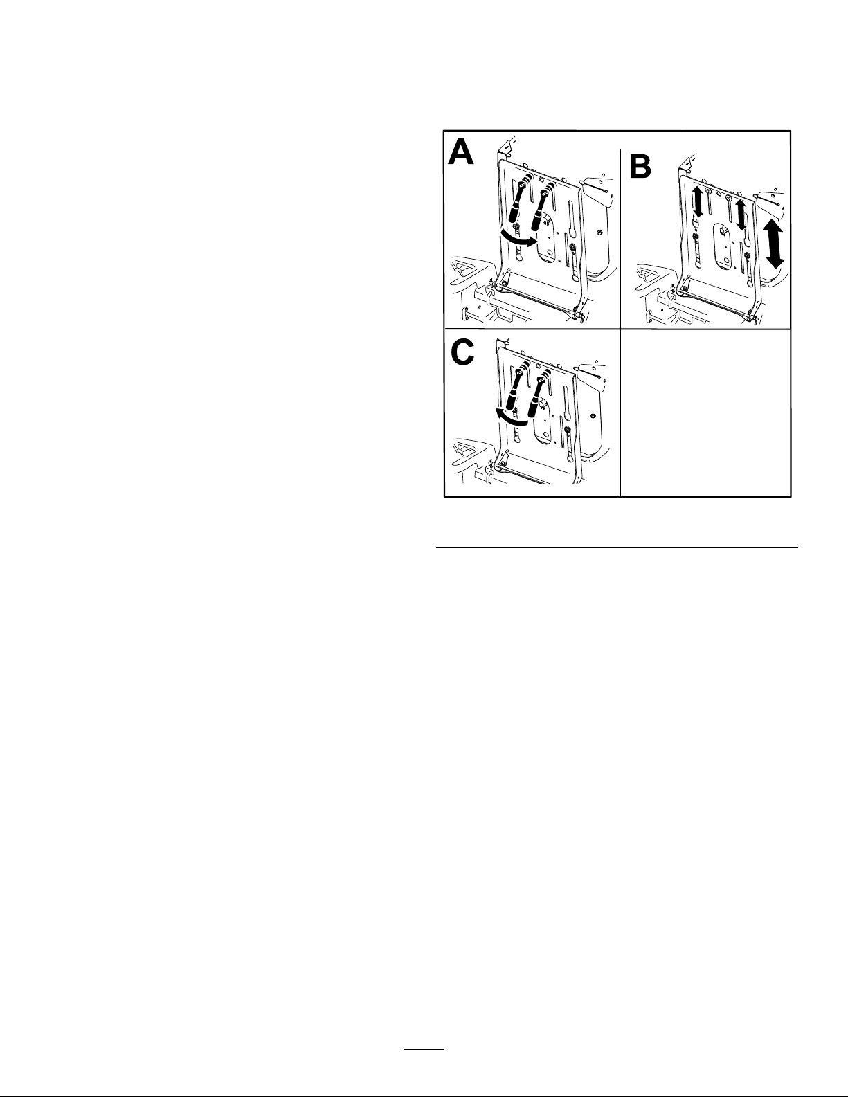
PositioningtheSteering Wheel
Thesteeringwheelhas3positionsforoperationand
1full-upposition.Usethefull-uppositionforstepping
onandoffthemachineandgettingoutoftheseat.
Whenoperatingthemachine,positionthesteering
wheelwhereyouhavethebestcontrolofthemachine
andaremostcomfortable.
1.Pressyourfootontothesteering-columnrelease
lever.
2.Positionthesteeringwheeltothedesired
position(Figure10).
Figure10
DuringOperation
DuringOperationSafety
GeneralSafety
•Theowner/operatorcanpreventandisresponsible
foraccidentsthatmaycausepersonalinjuryor
propertydamage.
•Wearappropriateclothing,includingeye
protection;longpants;slip-resistant,substantial
footwear;andhearingprotection.Tiebacklong
hairanddonotwearjewelry.
•Donotoperatethemachinewhileill,tired,or
undertheinuenceofalcoholordrugs.
•Nevercarrypassengersonthemachineandkeep
bystandersandpetsawayfromthemachine
duringoperation.
•Operatethemachineonlyingoodvisibilitytoavoid
holesorhiddenhazards.
•Avoidmowingonwetgrass.Reducedtraction
couldcausethemachinetoslide.
•Ensurethatalldrivesareinneutral,theparking
brakeisengaged,andyouareintheoperating
positionbeforeyoustarttheengine.
•Keepyourhandsandfeetawayfromthecutting
g027751
units.Keepclearofthedischargeopeningatall
times.
•Lookbehindanddownbeforebackinguptobe
sureofaclearpath.
•Usecarewhenapproachingblindcorners,shrubs,
trees,orotherobjectsthatmayobscureyour
vision.
•Donotmowneardrop-offs,ditches,or
embankments.Themachinecouldsuddenlyroll
overifawheelgoesovertheedgeoriftheedge
givesway.
•Stopthebladeswheneveryouarenotmowing.
•Stopthemachineandinspectthebladesafter
strikinganobjectorifthereisanabnormal
vibrationinthemachine.Makeallnecessary
repairsbeforeresumingoperation.
•Slowdownandusecautionwhenmakingturns
andcrossingroadsandsidewalkswiththe
machine.Alwaysyieldtheright-of-way.
•Disengagethedrivetothecuttingunitandshut
offtheenginebeforeadjustingtheheightof
cut(unlessyoucanadjustitfromtheoperating
position).
•Neverrunanengineinanareawhereexhaust
gasesareenclosed.
•Neverleavearunningmachineunattended.
18
Page 19

•Beforeleavingtheoperatingposition(including
toemptythecatchersortounclogthechute),do
thefollowing:
–Stopthemachineonlevelground.
–Disengagethepowertake-offandlowerthe
attachments.
–Engagetheparkingbrake.
–Shutofftheengineandremovethekey.
–Waitforallmovingpartstostop.
•Donotoperatethemachinewhenthereistherisk
oflightning.
•Donotusethemachineasatowingvehicleunless
ithasahitchinstalled.
•Donotchangethegovernorspeedoroverspeed
theengine.
•Useonlyaccessoriesandattachmentsapproved
byToro.
•Thismachineproducessoundlevelsinexcess
of85dBAattheoperator’searandcancause
hearinglossthroughextendedperiodsof
exposure.
quicklyaffecttheoperationofthemachineon
aslope.
•Identifyhazardsatthebaseoftheslope.Do
notoperatethemachineneardrop-offs,ditches,
embankments,water,orotherhazards.The
machinecouldsuddenlyrolloverifawheelgoes
overtheedgeortheedgecollapses.Keepasafe
distance(twicethewidthofthemachine)between
themachineandanyhazard.Useawalk-behind
machineorahandtrimmertomowthegrassin
theseareas.
•Avoidstarting,stopping,orturningthemachineon
slopes.Avoidmakingsuddenchangesinspeedor
direction;turnslowlyandgradually.
•Donotoperateamachineunderanyconditions
wheretraction,steering,orstabilityisinquestion.
Beawarethatoperatingthemachineonwet
grass,acrossslopes,ordownhillmaycausethe
machinetolosetraction.Lossoftractiontothe
drivewheelsmayresultinslidingandalossof
brakingandsteering.Themachinecanslideeven
ifthedrivewheelsarestopped.
•Removeormarkobstaclessuchasditches,holes,
ruts,bumps,rocks,orotherhiddenhazards.T all
grasscanhideobstacles.Uneventerraincould
overturnthemachine.
Figure11
1.Wearhearingprotection.
SlopeSafety
•Slopesareamajorfactorrelatedtolossofcontrol
androlloveraccidents,whichcanresultinsevere
injuryordeath.Theoperatorisresponsiblefor
safeslopeoperation.Operatingthemachineon
anysloperequiresextracaution.Beforeusingthe
machineonaslope,dothefollowing:
–Reviewandunderstandtheslopeinstructions
inthemanualandonthemachine.
–Useanangleindicatortodeterminethe
approximateslopeangleofthearea.
–Neveroperateonslopesgreaterthan15
degrees.
•Useextracarewhileoperatingwithaccessoriesor
attachments,suchasgrass-collectionsystems.
Thesecanchangethestabilityofthemachine
g229846
andcausealossofcontrol.Followdirectionsfor
counterweights.
•Ifpossible,keepthedeckloweredtotheground
whileoperatingonslopes.Raisingthedeckwhile
operatingonslopescancausethemachineto
becomeunstable.
–Evaluatethesiteconditionsofthedayto
determineiftheslopeissafeformachine
operation.Usecommonsenseandgood
judgmentwhenperformingthisevaluation.
Changesintheterrain,suchasmoisture,can
19
Page 20

1.SafeZone—usethe
machinehereonslopes
lessthan15degreesor
atareas.
2.DangerZone—usea
walk-behindmowerand/or
ahandtrimmeronslopes
greaterthan15degrees
andneardrop-offsor
water.
3.Water
Figure12
4.W=widthofthemachine
5.Keepasafedistance
(twicethewidthofthe
machine)betweenthe
machineandanyhazard.
OperatingtheSmartPark
™
ParkingBrake
Theparkingbrakeisactivatedelectronically.
Engagetheparkingbrakeby1ofthefollowingactions:
•PressingtheSmartPark
™
switchtotheONposition
(Figure6).
•Theparkingbrakeengagesautomaticallywhen
theoperatorleavestheseatandthetraction
controlpedalisintheNEUTRALposition.
•Theparkingbrakeautomaticallyengages5to6
secondsaftertheignitionswitchisturnedtothe
g231393
OFFposition(ifitisnotalreadyengaged).
Disengagetheparkingbrakeby1ofthefollowing
actions:
•Tapthetraction-controlpedalforwardorreverse.
•PressingthebrakeswitchtotheOFFposition
(Figure6).
EngagingtheBlade-Control Switch(PTO)
TowingSafety
•Donotattachtowedequipmentexceptatthehitch
point.
•Followtheattachmentmanufacturer's
recommendationforweightlimitsfortowed
equipmentandtowingonslopes.Thetowed
weightmustnotexceedtheweightofthemachine,
operator,andballast.Usecounterweightsor
wheelweightsasdescribedintheattachment,or
inthetowingmachineOperator’sManual.
•Neverallowchildrenorothersnearthetowed
equipment.
•Onslopes,theweightofthetowedequipmentmay
causelossoftraction,increasedriskofrollover,
andlossofcontrol.Reducethetowedweightand
slowdown.
•Thestoppingdistanceincreaseswiththeweight
ofatowedload.Travelslowlyandallowextra
distancetostop.
•Makewideturnstokeeptheattachmentclearof
themachine.
g008945
Figure13
Note:Alwaysengagethebladeswiththethrottlein
theFASTposition(Figure14).
g187516
Figure14
20
Page 21

Disengagingthe
OperatingtheChoke
Blade-ControlSwitch
(PTO)
Figure15
OperatingtheThrottle
YoucanmovethethrottlecontrolbetweenFASTand
SLOWpositions(Figure16).
AlwaysusetheFASTpositionwhenengagingthePTO.
Usethechoketostartacoldengine.
1.Pullupthechokeknobtoengagethechoke
beforeusingthekeyswitch(Figure17).
Note:Ensurethatyoufullyengagethechoke.
Youmayneedtoholdtheknobupwhenyou
usethekeyswitch.
2.Pushdownthechoketodisengagethechoke
aftertheenginehasstarted(Figure17).
g009174
Figure16
g008959
Figure17
1.ONposition2.OFFposition
g187517
21
Page 22

StartingtheEngine
DrivingtheMachine
Note:Awarmorhotenginemaynotrequirechoking.
Important:Donotengagethestarterformore
than5secondsatatime.Engagingthestarter
motorformorethan5secondscandamagethe
startermotor.Iftheenginefailstostart,wait10
secondsbeforeoperatingtheenginestarteragain.
Thismachinehasthecharacteristicsofbothagarden
tractorandazero-turnmachine.Likeagarden
tractor,themachinehasafootpedalthatcontrolsthe
forwardandreversemotionalongwiththespeed,
andithasasteeringwheelthatcontrolsthedirection
andtheturningradius.Likeazero-turnmachine,
thereardrivewheelsoperateindependentlyofeach
other,enablingyoutomakesharpturnsandtoturn
indifferentdirectionsquickly.Thesecharacteristics
vastlyimprovethemaneuverabilityofthemachine,
buttheymayalsorequireyoutopracticedrivingifyou
areunfamiliarwiththistypeofmachine.
WARNING
Themachinecanspinveryrapidly.You
maylosecontrolofthemachineandcause
personalinjuryordamagetothemachine.
•Usecautionwhenmakingturns.
•Slowthemachinedownbeforemaking
sharpturns.
Thethrottlecontrolregulatestheenginespeedas
measuredinrpm(revolutionsperminute).Placing
thethrottlecontrolintheFASTpositioncanbebestfor
performance.Formostapplications,operatinginthe
FULL-THROTTLEpositionisdesirable.
Figure18
ShuttingOfftheEngine
1.Disengagethebladesbymovingthe
blade-controlswitchtotheOFFposition(Figure
18).
2.Engagetheparkingbrake;refertoOperating
theSmartPark
3.MovethethrottlecontroltotheFASTposition.
4.TurnthekeytotheOFFpositionandremove
thekey.
CAUTION
Childrenorbystandersmaybeinjuredifthey
moveorattempttooperatethemachinewhile
itisunattended.
Alwaysremovethekeyandengagethe
parkingbrakewhenleavingthemachine
unattended.
™
ParkingBrake(page20).
g027831
DrivingForwardorBackward
1.MovethethrottletotheFASTposition.
2.Releasetheparkingbrake.
3.Placeyourfootontothetraction-controlpedal
andslowlypressthetopofthepedaltogo
forward,orpressonthebottomofthepedalto
movebackward(Figure19).
Note:Thefartheryoumovethepedalineither
direction,thefasterthemachinemovesinthat
direction.
g027750
Figure19
1.Forward3.Backward
2.Traction-controlpedal
22
Page 23

4.T oslowdown,releasethepressureonthe
traction-controlpedal.
MowinginReverse
UsingtheSideDischarge
Themowerhasahingedgrassdeectorthat
dispersesclippingstothesideanddowntowardthe
turf.
Themachinehasaninterlockfeaturethatprevents
themowerdeckfrommowingwhilethemachineis
travelinginreverse.Ifyoushiftintoreversewiththe
PTOengaged,thePTOstops.Ifyouneedtomow
whileinreversegear,youcantemporarilydeactivate
thisinterlock.
Note:Donotmowwhilebackingupunlessitis
necessary.
DANGER
Achildorbystandercouldbebackedover
byaridingmowerwithbladesengagedand
causeseriouspersonalinjuryordeath.
•Donotmowinreverseunlessabsolutely
necessary.
•Alwayslookbackwardanddownbefore
backingup.
•UsetheKeyChoiceswitchonlyifyouare
certainnochildrenorotherbystanderswill
appearinthemowingarea.
•Alwaysremoveboththeignitionand
KeyChoicekeysandputtheminasafe
placeoutofthereachofchildrenor
unauthorizeduserswhenleavingthe
machineunattended.
DANGER
Withoutagrassdeector,dischargecover,or
acompletegrass-catcherassemblymounted
inplace,youandothersareexposedtoblade
contactandthrowndebris.Contactwith
rotatingmowerblade(s)andthrowndebris
willcauseinjuryordeath.
•Neverremovethegrassdeectorfromthe
mowerdeckbecausethegrassdeector
routesmaterialdowntowardtheturf.Ifthe
grassdeectoriseverdamaged,replaceit
immediately.
•Neverputyourhandsorfeetunderthe
mowerdeck.
•Nevertrytoclearthedischargearea
ormowerbladesunlessyoumovethe
blade-controlswitch(PTO)totheOFF
position,rotatethekeyswitchtotheOFF
position,andremovethekeyfromthekey
switch.
•Makesurethatthegrassdeectorisinthe
downposition.
Ifyouarecertainthatyoucansafelymoworoperate
anattachmentinreverse,completethefollowing
procedure:
1.InserttheKeyChoicekeyintotheKeyChoice
switch(Figure7).
2.EngagethePTO.
3.TurntheKeyChoicekeyclockwiseuntilitstops
andreleaseit.
Note:Aredlightilluminatingontheconsole
indicatesthattheinterlockhasbeendeactivated.
4.Performthemowing.
5.Whennishedmowing,removetheKeyChoice
key(Figure7).
Note:Onceyoudeactivatetheinterlock,it
staysinthismode—withyourmowerbladeor
PTOpoweredattachmentoperatingwhenever
youbackup—andtheconsolelightstayson
untilyoueitherdisengagethePTOorshutoff
theengine.
23
Page 24

AdjustingtheHeightofCut
AdjustingtheAnti-Scalp
Note:Thetransportpositionisthehighest
height-of-cutpositionorcuttingheightat115mm
(4-1/2inches)asshowninFigure20.
Heightofcutiscontrolledbytheleverlocatedtothe
rightoftheoperatingposition(Figure20).
Rollers
AdjustingtheAnti-ScalpRollers
Machineswith107cm(42-inch)MowerDecks
Wheneveryouchangetheheightofcut,adjustthe
heightoftheanti-scalprollers.
Note:Adjusttheanti-scalprollerssothattherollers
donottouchthegroundinnormal,atmowingareas.
1.Parkthemachineonalevelsurface,disengage
theblade-controlswitchandengagetheparking
brake.
2.Shutofftheengine,removethekey ,andwait
forallmovingpartstostopbeforeleavingthe
operatingposition.
3.Adjusttheanti-scalprollersto1ofthefollowing
positions:
•Upperhole—usethispositionwiththemower
deckinthe63mm(2-1/2inches)andbelow
theheight-of-cutpositions(Figure21).
•Lowerhole—usethispositionwiththemower
deckinthe76mm(3inches)andabovethe
height-of-cutpositions(Figure21).
Figure20
g028025
g019929
Figure21
1.Anti-scalproller4.Upperhole—themower
2.Lowerhole—themower
deckinthe76mm(3
inches)andabovethe
height-of-cutpositions
3.Flangenut
deckinthe63mm(2-1/2
inches)andbelowthe
height-of-cutpositions
5.Bolt
AdjustingtheAnti-ScalpRollers
Machineswith127cm(50-inch)MowerDecks
Wheneveryouchangetheheightofcut,adjustthe
heightoftheanti-scalprollers.
Note:Adjusttheanti-scalprollerssothattherollers
donottouchthegroundinnormal,atmowingareas.
24
Page 25

1.Parkthemachineonalevelsurface,disengage
theblade-controlswitchandengagetheparking
brake.
2.Shutofftheengine,removethekey ,andwait
forallmovingpartstostopbeforeleavingthe
operatingposition.
3.Adjusttheanti-scalprollers(Figure22)tomatch
theclosestheight-of-cutposition.
Figure22
1.Anti-scalproller3.Flangenut
2.Bolt
4.Holespacing
AlternatingtheMowingDirection
Alternatethemowingdirectiontokeepthegrass
standingstraight.Thisalsohelpsdisperseclippings,
whichenhancesdecompositionandfertilization.
MowingatCorrectIntervals
Grassgrowsatdifferentratesatdifferenttimesof
theyear.Tomaintainthesamecuttingheight,mow
moreofteninearlyspring.Asthegrassgrowthrate
slowsinmidsummer,mowlessfrequently.Ifyou
cannotmowforanextendedperiod,rstmowata
highcuttingheight,thenmowagain2dayslaterata
lowerheightsetting.
UsingaSlowerCuttingSpeed
Toimprovecutquality,useaslowergroundspeed
incertainconditions.
g010233
AvoidingCuttingTooLow
Whenmowinguneventurf,raisethecuttingheight
toavoidscalpingtheturf.
OperatingTips
UsingtheFastThrottleSetting
Forbestmowingandmaximumaircirculation,operate
theengineattheFASTposition.Airisrequiredto
thoroughlycutgrassclippings,sodonotsetthe
height-of-cutsolowastototallysurroundthemower
deckinuncutgrass.Alwaystrytohave1sideofthe
mowerdeckfreefromuncutgrass,whichallowsair
tobedrawnintothemowerdeck.
CuttingaLawnfortheFirstTime
Cutgrassslightlylongerthannormaltoensurethat
thecuttingheightofthemowerdeckdoesnotscalp
anyunevenground.However,thecuttingheight
usedinthepastisgenerallythebestonetouse.
Whencuttinggrasslongerthan15cm(6inches)tall,
youmaywanttocutthelawntwicetoensurean
acceptablequalityofcut.
CuttingaThirdoftheGrassBlade
Itisbesttocutonlyaboutathirdofthegrassblade.
Cuttingmorethanthatisnotrecommendedunless
grassissparse,oritislatefallwhengrassgrows
moreslowly.
StoppingtheMachine
Ifyoumuststoptheforwardmotionofthemachine
whilemowing,aclumpofgrassclippingsmay
dropontoyourlawn.Toavoidthis,moveontoa
previouslycutareawiththebladesengagedoryou
candisengagethemowerdeckwhilemovingforward.
KeepingtheUndersideofthe
MowerDeckClean
Cleanclippingsanddirtfromtheundersideofthe
mowerdeckaftereachuse.Ifgrassanddirtbuildup
insidethemowerdeck,cuttingqualitywilleventually
becomeunsatisfactory.
MaintainingtheBlade(s)
Maintainasharpbladethroughoutthecuttingseason
becauseasharpbladecutscleanlywithouttearingor
shreddingthegrassblades.Tearingandshredding
turnsgrassbrownattheedges,whichslowsgrowth
andincreasesthechanceofdisease.Checkthe
mowerbladesaftereachuseforsharpness,and
foranywearordamage.Filedownanynicksand
sharpenthebladesasnecessary.Ifabladeis
damagedorworn,replaceitimmediatelywitha
genuineT ororeplacementblade.
25
Page 26

AfterOperation
AfterOperationSafety
GeneralSafety
•Cleangrassanddebrisfromthecuttingunits,
mufers,andenginecompartmenttohelpprevent
res.Cleanupoilorfuelspills.
•Shutoffthefuelbeforestoringortransportingthe
machine.
•Disengagethedrivetotheattachmentwhenever
youaretransportingornotusingthemachine.
•Allowtheenginetocoolbeforestoringthemachine
inanyenclosure.
•Neverstorethemachineorfuelcontainerwhere
thereisanopename,spark,orpilotlight,such
asonawaterheateroronotherappliances.
PushingtheMachineby Hand
Important:Alwayspushthemachinebyhand.
Donottowthemachine,becausetowingmay
damageit.
Figure23
1.Bypass-leverlocations
2.Leverpositionfor
operatingthemachine
6.Whennished,ensurethatthekeyhasbeen
returnedtotheSTOPpositiontoavoiddraining
thebatterycharge.
3.Leverpositionforpushing
themachine
Note:Ifthemachinefailstomove,theelectricbrake
maystillbeengaged.Youcanreleasetheelectric
brakemanuallyifnecessary;refertoReleasingthe
ElectricBrake(page40).
g017303
Thismachinehasanelectric-brakemechanism,and
topushthemachine,theignitionkeymustbeinthe
RUNposition.Thebatteryneedstobechargedand
functioningtodisengagetheelectricbrake.
PushingtheMachine
1.Parkthemachineonalevelsurface,disengage
theblade-controlswitch,andengagetheparking
brake.
2.Shutofftheengine,removethekey ,andwait
forallmovingpartstostopbeforeleavingthe
operatingposition.
3.Locatethebypassleversontheframeonboth
sidesoftheengine.
4.Movethebypassleversforwardthroughthekey
holeanddowntolocktheminplace(Figure23).
Note:Dothisforeachlever.
5.Turntheignitionkeyonanddisengagethe
parkingbrake.
Note:Donotstartthemachine.
OperatingtheMachine
Movethebypassleversrearwardthroughthekeyhole
anddowntolocktheminplaceasshowninFigure23.
Note:Dothisforeachlever.
26
Page 27

TransportingtheMachine
Useaheavy-dutytrailerortrucktotransportthe
machine.Useafull-widthramp.Ensurethatthetrailer
ortruckhasallthenecessarybrakes,lighting,and
markingasrequiredbylaw.Pleasecarefullyreadall
thesafetyinstructions.Knowingthisinformationcould
helpyouorbystandersavoidinjury.Refertoyour
localordinancesfortrailerandtie-downrequirements.
WARNING
Drivingonthestreetorroadwaywithout
turnsignals,lights,reectivemarkings,ora
slow-moving-vehicleemblemisdangerous
andcanleadtoaccidents,causingpersonal
injury.
Donotdrivethemachineonapublicstreet
orroadway.
SelectingaTrailer
WARNING
Loadingamachineontoatrailerortruck
increasesthepossibilityoftip-overandcould
causeseriousinjuryordeath(Figure24).
•Useonlyafull-widthramp;donotuse
individualrampsforeachsideofthe
machine.
•Donotexceeda15-degreeanglebetween
therampandthegroundorbetweenthe
rampandthetrailerortruck.
•Ensurethatthelengthoftherampisat
least4timesaslongastheheightofthe
trailerortruckbedtotheground.This
ensuresthattherampangledoesnot
exceed15degreesonatground.
Figure24
1.Full-widthrampinstowed
position
2.Sideviewoffull-width
rampinloadingposition
3.Notgreaterthan
15degrees
4.Rampisatleast4times
aslongastheheightof
thetrailerortruckbedto
theground
5.H=heightofthetraileror
truckbedtotheground
6.Trailer
LoadingtheMachine
WARNING
Loadingamachineontoatrailerortruck
increasesthepossibilityoftip-overandcould
causeseriousinjuryordeath.
•Useextremecautionwhenoperatinga
machineonaramp.
g027996
•Backthemachineuptherampanddriveit
forwarddowntheramp.
•Avoidsuddenaccelerationordeceleration
whiledrivingthemachineonarampas
thiscouldcausealossofcontrolora
tip-oversituation.
27
Page 28

1.Ifusingatrailer,connectittothetowingvehicle
andconnectthesafetychains.
2.Ifapplicable,connectthetrailerbrakesand
lights.
3.Lowertheramp,ensuringthattheangle
betweentherampandthegrounddoesnot
exceed15degrees(Figure24).
4.Backthemachineuptheramp(Figure25).
Figure25
g028294
1.Backthemachineupthe
ramp.
2.Drivethemachineforward
downtheramp.
5.Shutofftheengine,removethekey,andengage
theparkingbrake.
6.Tiedownthemachinenearthefrontcaster
wheelsandtherearbumperwithstraps,chains,
cable,orropes(Figure26).Refertolocal
regulationsfortie-downrequirements.
Figure26
1.Tie-downloops
g027708
UnloadingtheMachine
1.Lowertheramp,ensuringthattheangle
betweentherampandthegrounddoesnot
exceed15degrees(Figure24).
2.Drivethemachineforwarddowntheramp
(Figure25).
28
Page 29

Maintenance
Note:Determinetheleftandrightsidesofthemachinefromthenormaloperatingposition.
RecommendedMaintenanceSchedule(s)
MaintenanceService
Interval
Aftertherst5hours
Beforeeachuseordaily
Aftereachuse
Every25hours
Every100hours
Every200hours
Beforestorage
MaintenanceProcedure
•Changetheengineoilandlter.
•Checktheaircleanerfordirty,loose,ordamagedparts.
•Checktheengine-oillevel.
•Cleantheairintakescreen.
•Inspecttheblades.
•Inspectthegrassdeectorfordamage.
•Checkandcleanthefrontofthemachine.
•Cleanthemower-deckhousing.
•Greaseallthelubricationpoints.
•Cleantheair-cleanerfoamelement(moreoftenindusty,dirtyconditions).
•Checktirepressure.
•Replacetheair-cleanerfoamelement(moreoftenindusty,dirtyconditions).
•Cleanthepaperair-cleanerelement(moreoftenindirtyordustyconditions).
•Changetheengineoilandoillter(moreoftenindirtyordustyconditions).
•Checkthesparkplug(s).
•Checkthein-linefuellter.
•Replacethepaperair-cleanerelement(moreoftenindirtyordustyconditions).
•Replacethesparkplug(s).
•Replacethein-linefuellter.
•Chargethebatteryanddisconnectthebatterycables.
•Performallmaintenanceprocedureslistedabovebeforestorage.
•Paintanychippedsurfaces.
CAUTION
Ifyouleavethekeyintheswitch,someonecouldaccidentlystarttheengineandseriously
injureyouorotherbystanders.
Removethekeyfromtheswitchbeforeyouperformanymaintenance.
29
Page 30

Pre-Maintenance
RaisingtheSeat
Procedures
MaintenanceSafety
•Beforerepairingthemachinedothefollowing:
–Disengagethedrives.
–Engagetheparkingbrake.
–Shutofftheengineandremovethekey.
–Disconnectthespark-plugwire.
•Parkthemachineonalevelsurface.
•Cleangrassanddebrisfromthecuttingunit,
drives,mufers,andenginetohelppreventres.
•Cleanupoilorfuelspills.
•Donotallowuntrainedpersonneltoservicethe
machine.
•Usejackstandstosupportthemachineand/or
componentswhenrequired.
•Carefullyreleasepressurefromcomponentswith
storedenergy.
Ensurethattheparkingbrakeisengaged.Liftthe
seatforward.
Youcanaccessfollowingcomponentsbyraisingthe
seat:
•Serialplate
•Servicedecal
•Seat-adjustmentbolts(ifapplicable)
•Fuellter
•Batteryandbatterycables
RaisingtheFrontofthe Machine
Ifthefrontofthemachineneedstoberaised,usethe
veryfrontedgeasshowninFigure27.
Important:Topreventdamagetothesteering
mechanism,usetheveryfrontedgeofthe
machineforajackingpoint.
•Disconnectthebatteryorremovethespark-plug
wirebeforemakinganyrepairs.Disconnectthe
negativeterminalrstandthepositiveterminal
last.Connectthepositiveterminalrstand
negativelast.
•Usecarewhencheckingtheblades.Wrapthe
blade(s)orwearthicklypaddedgloves,anduse
cautionwhenservicingthem.Onlyreplaceblades;
donotstraightenorweldthem.
•Keepyourhandsandfeetawayfrommoving
parts.Ifpossible,donotmakeadjustmentswith
theenginerunning.
•Keepallpartsingoodworkingcondition
andallhardwaretightened,especiallythe
blade-attachmentbolts.Replaceallwornor
damageddecals.
•Neverinterferewiththeintendedfunctionofa
safetydeviceorreducetheprotectionprovided
byasafetydevice.Checktheirproperoperation
regularly.
•Toensureoptimumperformanceandcontinued
safetycerticationofthemachine,useonly
genuineT ororeplacementpartsandaccessories.
Replacementpartsandaccessoriesmadeby
othermanufacturerscouldbedangerous,and
suchusecouldvoidtheproductwarranty.
g028320
Figure27
•Checktheparkingbrakeoperationfrequently.
Adjustandserviceasrequired.
30
Page 31

Lubrication
EngineMaintenance
GreasingtheBearings
ServiceInterval:Every25hours—Greaseallthe
lubricationpoints.
GreaseType:No.2lithiumgrease
1.Parkthemachineonalevelsurface,disengage
theblade-controlswitch,andengagetheparking
brake;refertoShuttingOfftheEngine(page22).
2.Shutofftheengine,removethekey ,andwait
forallmovingpartstostopbeforeleavingthe
operatingposition.
3.Cleanthegreasettings(Figure28andFigure
29)witharag.
Note:Scrapeanypaintoffthefrontofthe
tting(s).
EngineSafety
•Shutofftheenginebeforecheckingtheoilor
addingoiltothecrankcase.
•Keepyourhands,feet,face,clothing,andother
bodypartsawaythemuferandotherhotsurfaces.
ServicingtheAirCleaner
ServiceInterval:Beforeeachuseordaily
Note:Servicetheaircleanermorefrequently(every
fewhours)ifoperatingconditionsareextremelydusty
orsandy.
RemovingtheFoamandPaper Elements
1.Parkthemachineonalevelsurface,disengage
theblade-controlswitch(PTO),andengagethe
parkingbrake.
2.Shutofftheengine,removethekey ,andwait
forallmovingpartstostopbeforeleavingthe
operatingposition.
Figure28
1.Frontcastertire
Figure29
Locatedontheseat-panunderside
1.Readtheinstructions
beforeservicingor
performingmaintenance
2.Checkthetirepressure
every25operatinghours
4.Connectagreaseguntoeachtting(Figure28
andFigure29).
3.Greaseevery25operating
hours
4.Engine
3.Cleanaroundtheair-cleanercovertoprevent
g027752
decal106-8717
dirtfromgettingintotheengineandcausing
damage.
4.Liftthecoverandrotatetheair-cleanerassembly
outoftheengine(Figure30).
5.Pumpgreaseintothettingsuntilgreasebegins
tooozeoutofthebearings.
6.Wipeupanyexcessgrease.
31
Page 32

ServicingtheFoamAir-Cleaner Element
ServiceInterval:Every25hours/Monthly(whichever
comesrst)—Cleantheair-cleaner
foamelement(moreoftenindusty,
dirtyconditions).
Every100hours/Y early(whichevercomes
rst)—Replacetheair-cleanerfoamelement
(moreoftenindusty,dirtyconditions).
g027800
1.Washthefoamelementinliquidsoapand
warmwater.Whentheelementisclean,rinse
itthoroughly.
2.Drytheelementbysqueezingitinacleancloth.
Important:Replacethefoamelementifit
istornorworn.
ServicingthePaperAir-Cleaner Element
ServiceInterval:Every100hours—Cleanthepaper
air-cleanerelement(moreoftenin
dirtyordustyconditions).
Figure30
5.Separatethefoamandpaperelements(Figure
31).
Figure31
Every200hours—Replacethepaperair-cleaner
g027801
element(moreoftenindirtyordustyconditions).
1.Cleanthepaperelementbytappingitgentlyto
removedust.
Note:Ifitisverydirty,replacethepaper
elementwithanewone.
2.Inspecttheelementfortears,anoilylm,or
damagetotherubberseal.
3.Replacethepaperelementifitisdamaged.
Important:Donotcleanthepaperlter.
g027802
32
Page 33

InstallingtheAirCleaner
1.Installthefoamelementoverthepaperelement.
ServicingtheEngineOil
Note:Ensurethatyoudonotdamagethe
elements.
2.Aligntheholesofthelterintothemanifold
ports.
3.Rotatethelterdownintothechamberandfully
seatitagainstthemanifold(Figure32).
Figure32
Engine-OilSpecications
OilType:Detergentoil(APIserviceSF,SG,SH,SJ,
orSL)
CrankcaseCapacity:2.4L(81oz)withoillter
Viscosity:Seethetablebelow.
g029683
Figure33
CheckingtheEngine-OilLevel
g228022
ServiceInterval:Beforeeachuseordaily
Note:Checktheoilwhentheengineiscold.
4.Closethecover.
Important:Ifyouoverllorunderlltheengine
crankcasewithoilandruntheengine,youmay
damagetheengine.
1.Parkthemachineonalevelsurface,disengage
theblade-controlswitch(PTO),andengagethe
parkingbrake.
2.Shutofftheengine,removethekey ,andwait
forallmovingpartstostopbeforeleavingthe
operatingposition.
Note:Ensurethattheengineiscoolsothatthe
oilhashadtimetodrainintothesump.
3.T okeepdirt,grassclippings,etc.,outofthe
engine,cleantheareaaroundtheoil-llcapand
dipstickbeforeremovingit(Figure34).
33
Page 34

Figure34
g027799
g193541
ChangingtheEngineOilandOil Filter
ServiceInterval:Aftertherst5hours/Afterthe
rstmonth(whichevercomes
rst)—Changetheengineoiland
lter.
Every100hours/Y early(whichevercomes
rst)—Changetheengineoilandoillter(more
oftenindirtyordustyconditions).
1.Parkthemachineonalevelsurfacetoensure
thattheoildrainscompletely.
2.Disengagetheblade-controlswitch(PTO)and
engagetheparkingbrake.
3.Shutofftheengine,removethekey ,andwait
forallmovingpartstostopbeforeleavingthe
operatingposition.
4.Draintheoilfromtheengine.
g029570
Figure35
34
Page 35

5.Changetheengine-oillter(Figure36).
Note:Ensurethattheoil-ltergaskettouches
theengineandthenturnthelteranextra3/4
turn.
g193530
Figure37
Figure36
6.Slowlypourapproximately80%ofthespecied
oilintothellertubeandslowlyaddthe
additionaloiltobringittotheFullmark(Figure
37).
7.Disposeoftheusedoilatarecyclingcenter.
ServicingtheSparkPlug
ServiceInterval:Every100hours/Yearly(whichever
g027477
Every200hours/Every2years(whichever
comesrst)—Replacethesparkplug(s).
Ensurethattheairgapbetweenthecenterandside
electrodesiscorrectbeforeinstallingthesparkplug.
Useasparkplugwrenchforremovingandinstalling
thesparkplugandagappingtoolorfeelergaugeto
checkandadjusttheairgap.Installanewsparkplug
ifnecessary.
Type:Champion
Airgap:0.76mm(0.03inch)
RemovingtheSparkPlug
1.Parkthemachineonalevelsurface,disengage
theblade-controlswitch(PTO),andengagethe
parkingbrake.
comesrst)—Checkthespark
plug(s).
®
RN9YCorNGK
®
BPR6ES
2.Shutofftheengine,removethekey ,andwait
forallmovingpartstostopbeforeleavingthe
operatingposition.
3.Cleantheareaaroundthebaseoftheplugto
keepdirtanddebrisoutoftheengine.
4.Removethesparkplug(Figure38).
35
Page 36

CleaningtheCooling System
1.Parkthemachineonalevelsurface,disengage
theblade-controlswitch(PTO),andengagethe
parkingbrake.
Figure38
CheckingtheSparkPlug
Important:Donotcleanthesparkplug(s).
Alwaysreplacethesparkplug(s)whenithasa
blackcoating,wornelectrodes,anoilylm,or
cracks.
Ifyouseelightbrownorgrayontheinsulator,the
engineisoperatingproperly.Ablackcoatingonthe
insulatorusuallymeanstheaircleanerisdirty .
Setthegapto0.75mm(0.03inch).
g027478
2.Shutofftheengine,removethekey ,andwait
forallmovingpartstostopbeforeleavingthe
operatingposition.
3.Removetheairlterfromtheengine.
4.Removetheengineshroud.
5.T opreventdebrisenteringtheairintake,install
theairltertothelterbase.
6.Cleandebrisandgrassfromtheparts.
7.Removetheairlterandinstalltheengine
shroud.
8.Installtheairlter.
Figure39
InstallingtheSparkPlug
Figure40
g206628
g027960
36
Page 37

FuelSystem
Maintenance
DANGER
Incertainconditions,fuelisextremely
ammableandhighlyexplosive.Areor
explosionfromfuelcanburnyou,others,and
candamageproperty.
•Performanyfuel-relatedmaintenance
whentheengineiscold.Dothisoutdoors
inanopenarea.Wipeupanyfuelthat
spills.
•Neversmokewhendrainingfuel,andstay
awayfromanopenameorwhereaspark
mayignitethefuelfumes.
ReplacingtheIn-LineFuel Filter
g027939
ServiceInterval:Every100hours/Yearly(whichever
comesrst)—Checkthein-linefuel
lter.
Every200hours/Every2years(whichever
comesrst)—Replacethein-linefuellter.
Neverinstalladirtylterafterremovingitfromthe
fuelline.
1.Parkthemachineonalevelsurface,disengage
theblade-controlswitch(PTO),andengagethe
parkingbrake.
2.Shutofftheengine,removethekey ,andwait
forallmovingpartstostopbeforeleavingthe
operatingposition.
g033082
Figure41
37
Page 38

ElectricalSystem
Note:Retainallfasteners.
Maintenance
ElectricalSystemSafety
•Disconnectthebatterybeforerepairingthe
machine.Disconnectthenegativeterminalrst
andthepositivelast.Connectthepositiveterminal
rstandthenegativelast.
•Chargethebatteryinanopen,well-ventilated
area,awayfromsparksandames.Unplugthe
chargerbeforeconnectingordisconnectingthe
battery.Wearprotectiveclothinganduseinsulated
tools.
WARNING
CALIFORNIA
Proposition65Warning
Batteryposts,terminals,andrelated
accessoriescontainleadandlead
compounds,chemicalsknownto
theStateofCaliforniatocause
cancerandreproductiveharm.Wash
handsafterhandling.
WARNING
Incorrectlyremovingthecablesfrom
batterycoulddamagethemachineand
cables,causingsparks.Sparkscan
causethebatterygassestoexplode,
resultinginpersonalinjury.
•Alwaysdisconnectthenegative
(black)batterycablebefore
disconnectingthepositive(red)
cable.
•Alwaysconnectthepositive(red)
batterycablebeforeconnectingthe
negative(black)cable.
5.Slidetherubbercoveroffthepositive(red)
cable.
6.Disconnectthepositive(red)cablefromthe
batterypost(Figure42).
Note:Retainallfasteners.
7.Removethebatteryhold-down(Figure42),and
liftthebatteryfromthebatterytray.
ServicingtheBattery
RemovingtheBattery
WARNING
Batteryterminalsormetaltoolscouldshort
againstmetalmachinecomponents,causing
sparks.Sparkscancausethebatterygasses
toexplode,resultinginpersonalinjury.
•Whenremovingorinstallingthebattery,
donotallowthebatteryterminalstotouch
anymetalpartsofthemachine.
•Donotallowmetaltoolstoshortbetween
thebatteryterminalsandmetalpartsofthe
machine.
1.Parkthemachineonalevelsurface,disengage
theblade-controlswitch(PTO),andengagethe
parkingbrake.
2.Shutofftheengine,removethekey ,andwait
forallmovingpartstostopbeforeleavingthe
operatingposition.
3.Raisetheseattoaccessthebattery.
4.Disconnectthenegative(black)groundcable
fromthebatterypost(Figure42).
Figure42
1.Battery
2.Positive(+)batterypost
3.Bolt,washer,andnut7.Batteryhold-down
4.Terminalboot
5.Negative(–)batterypost
6.Wingnut,washer,andbolt
ChargingtheBattery
ServiceInterval:Beforestorage—Chargethebattery
anddisconnectthebatterycables.
1.Removethebatteryfromthechassis;referto
RemovingtheBattery(page38).
g017701
38
Page 39

2.Chargethebatteryforaminimumof1hourat
6to10A.
Note:Donotoverchargethebattery .
3.Whenthebatteryisfullycharged,unplug
thechargerfromtheelectricaloutlet,then
disconnectthechargerleadsfromthebattery
posts(Figure43).
Figure43
1.Positive(+)batterypost3.Red(+)chargerlead
2.Negative(–)batterypost4.Black(–)chargerlead
ServicingtheFuses
Theelectricalsystemisprotectedbyfuses.Itrequires
nomaintenance;however,ifafuseblows,checkthe
component/circuitforamalfunctionorshort.
Fusetype:
•Main—F1(30A,blade-type)
•ChargeCircuit—F2(25A,blade-type)
1.Removethescrewssecuringthecontrolpanel
tothemachine.
Note:Retainallfasteners.
2.Liftthecontrolpaneuptoaccessthemainwire
harnessandfuseblock(Figure44).
3.T oreplaceafuse,pulloutthefusetoremove
it(Figure44).
g000538
InstallingtheBattery
1.Positionthebatteryinthetray(Figure42).
2.Usingthefastenerspreviouslyremoved,install
thepositive(red)batterycabletothepositive
(+)batteryterminal.
3.Usingthefastenerspreviouslyremoved,install
thenegativebatterycabletothenegative(-)
batteryterminal.
4.Slidetheredterminalbootontothepositive
(red)batterypost.
5.Securethebatterywiththehold-down(Figure
42).
6.Lowertheseat.
g014921
Figure44
1.Main(30A)2.Chargecircuit(25A)
4.Returnthecontrolpaneltoitsoriginalposition.
Note:Usethescrewsremovedpreviouslyto
securethepaneltothemachine.
39
Page 40

DriveSystem
ReleasingtheElectric
Maintenance
CheckingtheTirePressure
ServiceInterval:Every25hours—Checktire
pressure.
Maintaintheairpressureinthefrontandreartiresas
specied.Uneventirepressurecancauseanuneven
cut.Checkthepressureatthevalvestem(Figure45).
Checkthetireswhentheyarecoldtogetthemost
accuratepressurereading.
Refertothemaximumpressuresuggestedbythetire
manufactureronthesidewallofthecasterwheeltires.
Inatethereardrive-wheeltiresto90kPa(13psi).
Brake
Youcanmanuallyreleasetheelectricbrakeby
rotatingthelinkarmsforward.Oncetheelectricbrake
isenergized,thebrakeresets.
1.TurnthekeytotheOFFpositionordisconnect
thebattery.
2.Locatetheshaftontheelectricbrakewherethe
brakelinkarmsareconnected(Figure46).
3.Rotatetheshaftforwardtoreleasethebrake.
1.Valvestem
Figure45
g000554
Figure46
1.Brake-linkarmontheelectricbrakecontrolmodule
2.Left,reartire
g027911
40
Page 41

BeltMaintenance
ReplacingtheMower-Deck Belt
Thesignsofawornbeltincludesquealingwhilethe
beltisrotating,bladesslippingwhilecuttinggrass,
andfrayededges,burnmarks,andcracksonthebelt.
Replacethemowerbeltifanyoftheseconditionsare
evident.
1.Parkthemachineonalevelsurface,disengage
theblade-controlswitch(PTO),andengagethe
parkingbrake.
2.Shutofftheengine,removethekey ,andwait
forallmovingpartstostopbeforeleavingthe
operatingposition.
3.Settheheight-of-cutatthelowestcutting
positionof38mm(1-1/2inches).
4.Removethepulleycovers(Figure47).
Figure48
MowerDeckswith2Blades
1.Idlerpulley
2.Mowerbelt
3.Outsidepulley6.Spring-removaltool
4.Spring
5.Enginepulley
g014930
Figure47
1.Cover2.Screw
5.Usingaspring-removaltool,(ToroPartNo.
92-5771),removetheidlerspringfromthedeck
hooktoremovetensionontheidlerpulley,and
rollthebeltoffthepulleys(Figure48andFigure
49).
WARNING
Thespringisundertensionwhen
installedandcancausepersonalinjury .
Becarefulwhenremovingthebelt.
g032555
g014931
Figure49
MowerDeckswith3Blades
1.Idlerpulley
2.Mowerbelt5.Enginepulley
3.Outsidepulley6.Spring-removaltool
4.Spring
6.Routethenewbeltaroundtheenginepulleyand
mowerpulleys(Figure49).
41
Page 42

7.Usingaspring-removaltool,installtheidler
springoverthedeckhook,andplacetensionon
theidlerpulleyandmowerbelt(Figure48and
Figure49).
8.Installthepulleycovers.
MowerMaintenance
ServicingtheCutting Blades
Toensureasuperiorqualityofcut,keeptheblades
sharp.Forconvenientsharpeningandreplacement,
keepextrabladesonhand.
BladeSafety
Awornordamagedbladecanbreak,andapieceof
thebladecouldbethrowntowardyouorbystanders,
resultinginseriouspersonalinjuryordeath.Tryingto
repairadamagedblademayresultindiscontinued
safetycerticationoftheproduct.
•Inspectthebladesperiodicallyforwearordamage.
•Usecarewhencheckingtheblades.Wrapthe
bladesorweargloves,andusecautionwhen
servicingtheblades.Onlyreplaceorsharpenthe
blades;neverstraightenorweldthem.
•Onmulti-bladedmachines,takecareasrotating1
bladecancauseotherbladestorotate.
BeforeInspectingorServicingthe Blades
1.Parkthemachineonalevelsurface,disengage
theblade-controlswitch(PTO),andengagethe
parkingbrake.
2.Shutofftheengine,removethekey,and
disconnectthespark-plugwiresfromthespark
plugs.
InspectingtheBlades
ServiceInterval:Beforeeachuseordaily
1.Inspectthecuttingedges(Figure50).
2.Iftheedgesarenotsharporhavenicks,remove
andsharpentheblade;refertoSharpeningthe
Blades(page44).
3.Inspecttheblades,especiallyinthecurvedarea.
4.Ifyounoticeanycracks,wear,oraslotforming
inthisarea,immediatelyinstallanewblade
(Figure50).
42
Page 43

Figure50
g006530
1.Cuttingedge3.Wear/slotforming
2.Curvedarea4.Crack
CheckingforBentBlades
Note:Themachinemustbeonalevelsurfacefor
thefollowingprocedure.
1.Raisethemowerdecktothehighest
height-of-cutposition.
2.Whilewearingthicklypaddedgloves,orother
adequatehandprotection,slowlyrotatethe
bladeintoapositionthatallowsyoutomeasure
thedistancebetweenthecuttingedgeandthe
levelsurfacethemachineison(Figure51).
Figure51
1.Deck3.Blade
2.Spindlehousing
3.Measurefromthetipofthebladetotheat
surface(Figure52).
g014973
Figure52
1.Blade(inpositionformeasuring)
2.Levelsurface
3.Measureddistancebetweenbladeandthesurface(A)
4.Rotatethesameblade180degreessothat
theopposingcuttingedgeisnowinthesame
position(Figure53).
g014974
Figure53
1.Blade(sidepreviouslymeasured)
2.Measurement(positionusedpreviously)
3.Opposingsideofbladebeingmovedintomeasurement
g014972
position
5.Measurefromthetipofthebladetotheat
surface(Figure54).
Note:Thevarianceshouldbenomorethan
3mm(1/8inch).
43
Page 44

Figure54
1.Oppositebladeedge(inpositionformeasuring)
2.Levelsurface
3.Secondmeasureddistancebetweenbladeandsurface(B)
A.IfthedifferencebetweenAandBisgreater
than3mm(1/8inch),replacethebladewith
anewblade;refertoRemovingtheBlades
(page44)andInstallingtheBlades(page
45).
g014973
g027833
Figure55
1.Sailareaoftheblade3.Curvedwasher
2.Blade4.Bladebolt
SharpeningtheBlades
1.Usealetosharpenthecuttingedgeatboth
endsoftheblade(Figure56).
Note:Ifabentbladeisreplacedwitha
newblade,andthedimensionobtained
continuestoexceed3mm(1/8inch),the
bladespindlecouldbebent.Contactan
AuthorizedServiceDealerforservice.
B.Ifthevarianceiswithinconstraints,moveto
thenextblade.
6.Repeatthisprocedureoneachblade.
RemovingtheBlades
Replacethebladesiftheyhitasolidobject,orifthe
bladeisoutofbalanceorbent.
1.Holdthebladeendusingaragorthicklypadded
glove.
2.Removethebladebolt,curvedwasher,and
bladefromthespindleshaft(Figure55).
Note:Maintaintheoriginalangle.
Note:Thebladeretainsitsbalanceifthesame
amountofmaterialisremovedfrombothcutting
edges.
g000552
Figure56
1.Sharpenatoriginalangle.
2.Checkthebalanceofthebladebyputtingitona
bladebalancer(Figure57).
Note:Ifthebladestaysinahorizontalposition,
thebladeisbalancedandcanbeused.
Note:Ifthebladeisnotbalanced,lesome
metalofftheendofthesailareaonly(Figure56).
Figure57
1.Blade2.Balancer
3.Repeatthisprocedureuntilthebladeis
balanced.
44
g000553
Page 45

InstallingtheBlades
1.Installthebladeontothespindleshaft(Figure
55).
Important:Thecurvedpartoftheblade
mustbepointingupwardtowardtheinside
ofthemowertoensurepropercutting.
2.Installthecurvedwasher(cuppedsidetoward
theblade)andthebladebolt(Figure55).
3.T orquethebladeboltto47to88N∙m(35to65
ft-lb).
LevelingtheMowerDeck
Checktoensurethatthemowerdeckislevelanytime
youinstallthemowerorwhenyouseeanunevencut
onyourlawn.
Checkthemowerdeckforbentbladespriorto
leveling,andremoveandreplaceanybentblades;
refertotheCheckingforBentBlades(page43)before
continuing.
Figure58
MowerDeckswith2Blades
1.Bladessidetoside
2.Sailareaoftheblade4.Measurefromthetipofthe
3.Outsidecuttingedges
bladetotheatsurface
here.
g009682
Levelthemowerdeckside-to-siderst;thenyoucan
adjustthefront-to-rearslope.
Requirements:
•Themachinemustbeonalevelsurface.
•Alltiresmustbeproperlyinated;refertoChecking
theTirePressure(page40).
LevelingfromSidetoSide
1.Parkthemachineonalevelsurface,disengage
theblade-controlswitch(PTO),andengagethe
parkingbrake.
2.Shutofftheengine,removethekey ,andwait
forallmovingpartstostopbeforeleavingthe
operatingposition.
3.Settheheight-of-cutlevertothemiddleposition.
4.Carefullyrotatethebladessothattheyareall
sidetoside(Figure58andFigure59).
Figure59
MowerDeckswith3Blades
1.Bladessidetoside
2.Sailareaoftheblade4.Measurefromthetipofthe
3.Outsidecuttingedges
bladetotheatsurface
here.
5.Measurebetweentheoutsidecuttingedgesand
theatsurface(Figure58andFigure59).
Note:Ifbothmeasurementsarenotwithin
5mm(3/16inch),anadjustmentisrequired;
continuewiththisprocedure.
6.Movetotheleftsideofthemachine.
7.Loosenthesidelockingnut.
8.Raiseorlowertheleftsideofthemowerdeck
byrotatingtherearnut(Figure60).
g005278
Note:Rotatetherearnutclockwiseto
raisethemowerdeck;rotatetherearnut
counter-clockwisetolowerthemowerdeck
(Figure60).
45
Page 46

Figure60
1.Hangerbracket3.Rearnut
2.Sidelockingnut
9.Checktheside-to-sideadjustmentsagain.
Repeatthisprocedureuntilthemeasurements
arecorrect.
g009658
Figure61
MowerDeckswith2Blades
1.Bladesfronttorear
2.Measurefromthetipofthebladetotheatsurfacehere.
g027588
10.Continuelevelingthemowerdeckbychecking
thefront-to-rearbladeslope;refertoAdjusting
theFront-to-RearBladeSlope(page46).
AdjustingtheFront-to-RearBlade Slope
Checkthefront-to-rearbladelevelanytimeyouinstall
themower.Ifthefrontofthemowerismorethan
7.9mm(5/16inch)lowerthantherearofthemower,
adjustthebladelevelusingthefollowinginstructions:
1.Parkthemachineonalevelsurface,disengage
theblade-controlswitch(PTO),andengagethe
parkingbrake.
2.Shutofftheengine,removethekey ,andwait
forallmovingpartstostopbeforeleavingthe
operatingposition.
3.Settheheight-of-cutlevertothemiddleposition.
Note:Checkandadjusttheside-to-sideblade
levelifyouhavenotcheckedthesetting;referto
LevelingfromSidetoSide(page45).
g009659
Figure62
MowerDeckswith3Blades
1.Bladesfronttorear3.Measurefromthetipofthe
bladetotheatsurface
here.
2.Outsidecuttingedges
5.Measurefromthetipofthefrontbladetotheat
surface,andthetipoftherearbladetotheat
surface(Figure61andFigure62).
Note:Ifthefrontbladetipisnot1.6to7.9mm
(1/16to5/16inch)lowerthantherearbladetip,
adjustthefrontlocknut.
6.T oadjustthefront-to-rearbladeslope,rotatethe
adjustmentnutinthefrontofthemower(Figure
63).
4.Carefullyrotatethebladessotheyarefacing
fronttorear(Figure61andFigure62).
46
Page 47

Figure63
1.Adjustingrod3.Locknut
2.Adjustingblock
7.T oraisethefrontofthemower,tightenthe
adjustmentnut.
8.T olowerthefrontofthemower,loosenthe
adjustmentnut.
9.Afteradjustment,checkthefront-to-rearslope
again,continueadjustingthenutuntilthefront
bladetipis1.6to7.9mm(1/16to5/16inch)
lowerthantherearbladetip(Figure61and
Figure62).
10.Whenthefront-to-rearbladeslopeiscorrect
checktheside-to-sidelevelofthemoweragain,
refertoLevelingfromSidetoSide(page45).
RemovingtheMowerDeck
1.Parkthemachineonalevelsurface,disengage
theblade-controlswitch(PTO),andengagethe
parkingbrake.
g014634
g014635
Figure64
1.Frontsupportrod3.Deckbracket
2.Lockingnut
5.Carefullylowerthefrontofthemowerdeckto
theground.
6.Liftthemowerdeckandhangerbracketsclear
oftherearliftrodandlowerthemowercarefully
totheground(Figure65).
2.Shutofftheengine,removethekey ,andwait
forallmovingpartstostopbeforeleavingthe
operatingposition.
3.Lowertheheight-of-cutlevertothelowest
position.
4.Removethehairpincotterfromthefrontsupport
rod,andremovetherodfromthedeckbracket
(Figure64).
Figure65
1.Mowerdeck
2.Hangerbracket
3.Rearliftrod
7.Slidethemowerdeckrearwardtoremovethe
mowerbeltfromtheenginepulley.
47
g005077
Page 48

8.Slidethemowerdeckoutfromunderneaththe
machine.
Note:Retainallpartsforfutureinstallation.
InstallingtheMowerDeck
1.Parkthemachineonalevelsurface,disengage
theblade-controlswitch(PTO),andengagethe
parkingbrake.
2.Shutofftheengine,removethekey ,andwait
forallmovingpartstostopbeforeleavingthe
operatingposition.
3.Slidethemowerunderthemachine.
4.Lowertheheight-of-cutlevertothelowest
position.
5.Lifttherearofthemowerdeckandguidethe
hangerbracketsovertherearliftrod(Figure65).
6.Attachthefrontsupportrodtothemowerdeck
withtheclevispinandhairpincotter(Figure64).
7.Installthemowerbeltontotheenginepulley;
refertoReplacingtheMower-DeckBelt(page
41).
ReplacingtheGrass
Deector
ServiceInterval:Beforeeachuseordaily—Inspect
thegrassdeectorfordamage.
WARNING
Anuncovereddischargeopeningcouldallow
themachinetothrowobjectstowardyouor
bystanders,resultinginseriousinjury.Also,
contactwiththebladecouldoccur.
Neveroperatethemachinewithoutthe
grassdeector,thedischargecover,orthe
grass-collectionsysteminplace.
1.Removethenut(3/8inch)fromtherodunder
themower(Figure66).
Figure66
1.Mowerdeck
2.Grassdeector6.Nut(3/8inch)
3.Grass-deectorbracket7.Shortstandoff
4.Rod
2.Slidetherodoutoftheshortstand-off,spring,
andgrassdeector(Figure66).
3.Removethedamagedorworngrassdeector.
4.Replacethegrassdeector(Figure66).
5.Slidetherod,straightend,throughtherear
grassdeectorbracket.
6.Placethespringontherod,withendwires
down,andbetweenthegrassdeectorbrackets.
7.Slidetherodthroughthesecondgrass-deector
bracket(Figure66).
8.Inserttherodatthefrontofthegrassdeector
intotheshortstandoffonthedeck.
9.Securetherearendoftherodintothemower
withanut(3/8inch)asshowninFigure66.
5.Spring
Important:Thegrassdeectormustbe
spring-loadedinthedownposition.Liftthe
deectoruptotestthatitsnapsintothe
full-downposition.
g005192
48
Page 49

Cleaning
CleaningundertheFrontof theMachine
ServiceInterval:Aftereachuse—Checkandclean
thefrontofthemachine.
Removedebrisunderthefrontofthemachinewith
compressedairorbyhandwithabrush(Figure67).
Note:Donotusewatertocleanunderthefrontofthe
machine;thiscancausebuildupofdebris.
Figure67
WashingtheUndersideof theMowerDeck
ServiceInterval:Aftereachuse—Cleanthe
mower-deckhousing.
Important:Youcanwashthemachinewithamild
detergentandwater.Donotpressurewashthe
machine.Avoidexcessiveuseofwater,especially
nearthecontrolpanel,undertheseat,aroundthe
engine,hydraulicpumps,andmotors.
Washtheundersideofthemowerdeckaftereachuse
topreventgrassbuildupforimprovedmulchaction
andclippingdispersal.
1.Parkthemachineonalevelsurface,disengage
theblade-controlswitch(PTO),andengagethe
parkingbrake.
2.Shutofftheengine,removethekey ,andwait
forallmovingpartstostopbeforeleavingthe
operatingposition.
3.Attachthehosecouplingtotheendofthe
mowerwashouttting,andturnthewateron
high(Figure68).
Note:Spreadpetroleumjellyonthewashout
ttingO-ringtomakethecouplingslideon
easierandprotecttheO-ring.
g020098
Figure68
1.Washouttting3.O-ring
2.Hose
4.Lowerthemowertothelowestheight-of-cut.
5.Sitontheseatandstarttheengine.
6.Engagetheblade-controlswitchandletthe
g028248
mowerrunfor1to3minutes.
7.Disengagetheblade-controlswitch,shutoffthe
engine,removethekey,andwaitforallmoving
partstostop.
8.Turnthewateroffandremovethecouplingfrom
thewashouttting.
4.Coupling
Note:Ifthemowerisnotcleanafter1washing,
soakitandletitstandfor30minutes.Then
repeattheprocess.
9.Runthemoweragainfor1to3minutesto
removeexcesswater.
WARNING
Abrokenormissingwashouttting
couldexposeyouandotherstothrown
objectsorbladecontact.Contactwitha
bladeorthrowndebriscancauseinjury
ordeath.
•Replacebrokenormissingwashout
ttingimmediately,beforeusing
machineagain.
•Neverputyourhandsorfeetunder
themowerorthroughopeningsinthe
machine.
DisposingofWaste
Engineoil,batteries,hydraulicuid,andengine
coolantarepollutantstotheenvironment.Disposeof
theseaccordingtoyourstateandlocalregulations.
49
Page 50

Storage
StorageSafety
•Lettheenginecoolbeforestoringthemachine.
•Donotstorethemachineorfuelnearamesor
drainthefuelindoors.
CleaningandStorage
1.Disengagetheblade-controlswitch(PTO),and
engagetheparkingbrake.
2.Shutofftheengine,removethekey ,andwait
forallmovingpartstostopbeforeleavingthe
operatingposition.
3.Removegrassclippings,dirt,andgrimefromthe
externalpartsoftheentiremachine,especially
theengineandhydraulicsystem.Cleandirtand
chafffromtheoutsideoftheenginecylinder
headnsandblowerhousing.
Important:Youcanwashthemachinewith
milddetergentandwater.Donotpressure
washthemachine.Avoidexcessiveuse
ofwater,especiallynearthecontrolpanel,
engine,hydraulicpumps,andmotors.
4.Checktheparkingbrakeoperation;referto
OperatingtheSmartPark
20).
5.Servicetheaircleaner;refertoServicingtheAir
Cleaner(page31).
6.Greasethemachine;refertoLubrication(page
31).
7.Changethecrankcaseoil;refertoChangingthe
EngineOilandOilFilter(page34).
8.Checkthetirepressure;refertoCheckingthe
TirePressure(page40).
™
ParkingBrake(page
tank.Followmixinginstructionsfrom
thestabilizermanufacturer.Donotuse
analcohol-basedstabilizer(ethanolor
methanol).
Note:Afuelstabilizer/conditionerismost
effectivewhenmixedwithfreshfueland
usedatalltimes.
B.Runtheenginetodistributeconditionedfuel
throughthefuelsystem(5minutes).
C.Shutofftheengine,allowittocool,and
drainthefueltank.
D.Starttheengineandrunituntilitstops.
E.Disposeoffuelproperly.Recyclethefuel
accordingtolocalcodes.
Important:Donotstore
stabilizer/conditionedfuelover
90days.
13.Removeandchecktheconditionofthespark
plug(s);refertoServicingtheSparkPlug(page
35).Withthesparkplug(s)removedfromthe
engine,pour30ml(2tablespoons)ofengine
oilintothesparkplughole.Usethestarterto
cranktheengineanddistributetheoilinsidethe
cylinder.Installthesparkplug(s).Donotinstall
thewireonthesparkplug(s).
14.Checkandtightenallbolts,nuts,andscrews.
Repairorreplaceanypartthatisdamaged.
15.Paintallscratchedorbaremetalsurfaces.Paint
isavailablefromyourAuthorizedServiceDealer.
16.Storethemachineinaclean,drygarageor
storagearea.Removethekeyfromtheswitch
andkeepitoutofreachofchildrenorother
unauthorizedusers.Coverthemachineto
protectitandkeepitclean.
9.Chargethebattery;refertoChargingtheBattery
(page38).
10.Scrapeanyheavybuildupofgrassanddirt
fromtheundersideofthemower,thenwashthe
mowerwithagardenhose.
Note:Runthemachinewiththeblade-control
switch(PTO)engagedandtheengineathigh
idlefor2to5minutesafterwashing.
11.Checktheconditionoftheblades;referto
ServicingtheCuttingBlades(page42).
12.Preparethemachineforstoragewhennon-use
occursover30days.Preparethemachinefor
storageasfollows:
A.Addapetroleumbased
stabilizer/conditionertofuelinthe
50
Page 51

StoringtheBattery
1.Fullychargethebattery.
2.Letthebatteryrestfor24hours,thencheckthe
batteryvoltage.
Note:Ifthebatteryvoltageisbelow12.6V ,
repeatsteps1and2.
3.Disconnectthecablesfromthebattery.
4.Checkthevoltageperiodicallytoensurethatthe
voltageis12.4Vorhigher.
Note:Ifthebatteryvoltageisbelow12.4V ,
repeatsteps1and2.
BatteryStorageTips
•Storethebatteryinacool,dryareainanupright
position.
•Donotstackbatteriesdirectlyontopofeachother,
unlesstheyareincartons.
•Donotstackmorethan3batteries(only2ifthe
batterytypeiscommercial).
•Testawetbatteryevery4to6monthsandcharge
it,ifnecessary.
•Alwaystestandchargethebatterybefore
installation.
51
Page 52

Troubleshooting
Problem
Thefueltankisshowingsignsofcollapsing
orthemachineisfrequentlyshowingsigns
ofrunningoutoffuel.
Theengineoverheats.
Thestarterdoesnotcrank.
Theenginedoesnotstart,startshard,or
failstokeeprunning.
PossibleCauseCorrectiveAction
1.Theair-cleanerpaperelementclogged.
1.Theengineloadisexcessive.1.Reducethegroundspeed.
2.Theoillevelinthecrankcaseislow.2.Addoiltothecrankcase.
3.Thecoolingnsandairpassages
undertheengine-blowerhousingare
plugged.
4.Theaircleanerisdirty.
5.Dirt,water,orstalefuelisinthefuel
system.
1.Thetraction-controlpedalisengaged.1.Movethetraction-controlpedalto
2.Thebatteryisdead.
3.Theelectricalconnectionsare
corrodedorloose.
4.Afuseisblown.4.Replacethefuse.
5.Arelayorswitchisdamaged.
1.Thefueltankisempty.1.Fillthefueltank.
2.Thechoke(ifapplicable)isnoton.
3.Theaircleanerisdirty.
4.Thespark-plugwire(s)islooseor
disconnected.
5.Thesparkplug(s)ispitted,fouled,or
thegapisincorrect.
6.Thereisdirtinfuellter.6.Replacethefuellter.
7.Dirt,water,orstalefuelisinfuel
system.
8.Thereisincorrectfuelinthefueltank.
9.Theoillevelinthecrankcaseislow.9.Addoiltothecrankcase.
1.Cleanthepaperelement.
3.Removetheobstructionfromthe
coolingnsandairpassages.
4.Cleanorreplacetheair-cleaner
element.
5.ContactanAuthorizedServiceDealer.
neutral.
2.Chargethebattery.
3.Checktheelectricalconnectionsfor
goodcontact.
5.ContactanAuthorizedServiceDealer.
2.MovethechokelevertotheON
position.
3.Cleanorreplacetheair-cleaner
element.
4.Installthewire(s)onthesparkplug.
5.Installanew,correctlygappedspark
plug(s).
7.ContactanAuthorizedServiceDealer.
8.Drainthetankandreplacethefuelwith
thepropertype.
Theenginelosespower.
1.Theengineloadisexcessive.1.Reducethegroundspeed.
2.Theaircleanerisdirty.
3.Theoillevelinthecrankcaseislow.3.Addoiltothecrankcase.
4.Thecoolingnsandairpassages
undertheengineblowerhousingare
plugged.
5.Thesparkplug(s)ispitted,fouled,or
thegapisincorrect.
6.Thefuel-tankventisblocked.6.ContactanAuthorizedServiceDealer.
7.Thereisdirtinthefuellter.7.Replacethefuellter.
8.Dirt,water,orstalefuelisinthefuel
system.
9.
Thereisincorrectfuelinthefueltank.
2.Cleantheair-cleanerelement.
4.Removetheobstructionfromthe
coolingnsandairpassages.
5.Installanew,correctlygappedspark
plug(s).
8.
ContactanAuthorizedServiceDealer.
9.Drainthetankandreplacethefuelwith
thepropertype.
52
Page 53

Problem
PossibleCauseCorrectiveAction
Themachinedoesnotdrive.
Themachinevibratesabnormally .
Thecuttingheightisuneven.
1.Thebypassvalvesareopen.
2.Thetractionbeltsareworn,loose,or
broken.
3.Thetractionbeltsareoffthepulleys.3.ContactanAuthorizedServiceDealer.
4.Thetransmissionhasfailed.4.ContactanAuthorizedServiceDealer.
1.Thecuttingblade(s)is/arebentor
unbalanced.
2.Theblademountingboltisloose.2.Tightentheblademountingbolt.
3.Theenginemountingboltsareloose.3.Tightentheenginemountingbolts.
4.Theenginepulley ,idlerpulley,orblade
pulleyisloose.
5.Theenginepulleyisdamaged.
6.Thebladespindleisbent.
7.Themotormountislooseorworn.
1.Theblade(s)isnotsharp.1.Sharpentheblade(s).
2.Acuttingblade(s)is/arebent.2.Installanewcuttingblade(s).
3.Themowerisnotlevel.
4.Ananti-scalproller(ifapplicable)isnot
setcorrectly .
5.Theundersideofthemowerdeckis
dirty.
6.Thetirepressureisincorrect.6.Adjustthetirepressure.
7.Abladespindleisbent.
1.Closethetowvalves.
2.ContactanAuthorizedServiceDealer.
1.Installnewcuttingblade(s).
4.Tightentheappropriatepulley.
5.ContactanAuthorizedServiceDealer.
6.ContactanAuthorizedServiceDealer.
7.ContactanAuthorizedServiceDealer.
3.Levelthemowerfromside-to-sideand
front-to-rear.
4.Adjusttheanti-scalpwheelheight.
5.Cleantheundersideofthemower
deck.
7.ContactanAuthorizedServiceDealer.
Thebladesdonotrotate.
1.Thedrivebeltisworn,looseorbroken.1.Installanewdrivebelt.
2.Thedrivebeltisoffofthepulley .
3.Thepower-takeoff(PTO)switchor
PTOclutchisfaulty.
4.Themowerbeltisworn,loose,or
broken.
2.Installthedrivebeltandcheckthe
adjustingshaftsandbeltguidesforthe
correctposition.
3.ContactanAuthorizedServiceDealer.
4.Installanewmowerbelt.
53
Page 54

Schematics
ElectricalDiagram(Rev .A)
54
g027754
Page 55

Notes:
Page 56

 Loading...