

Page 1

FormNo.3412-393RevA
TimeCutter
®
SS5000Riding
Mower
ModelNo.74731—SerialNo.400000000andUp
ModelNo.74775—SerialNo.400000000andUp
Registeratwww.T oro.com.
OriginalInstructions(EN)
*3412-393*A
Page 2
WARNING
CALIFORNIA
Proposition65Warning
Thisproductcontainsachemicalorchemicals
knowntotheStateofCaliforniatocausecancer,
birthdefects,orreproductiveharm.
Theengineexhaustfromthisproduct
containschemicalsknowntotheStateof
Californiatocausecancer,birthdefects,
orotherreproductiveharm.
ThissparkignitionsystemcomplieswithCanadianICES-002
ItisaviolationofCaliforniaPublicResourceCode
Section4442or4443touseoroperatetheengineonany
forest-covered,brush-covered,orgrass-coveredlandunless
theengineisequippedwithasparkarrester,asdenedin
Section4442,maintainedineffectiveworkingorderorthe
engineisconstructed,equipped,andmaintainedforthe
preventionofre.
GrossHorsepower
Thegrossornethorsepowerofthisenginewaslaboratory
ratedbytheenginemanufacturerinaccordancewiththe
SocietyofAutomotiveEngineers(SAE)J1940.Ascongured
tomeetsafety,emission,andoperatingrequirements,
theactualenginetorqueonthisclassofmowerwillbe
signicantlylower.
Gotowww .Toro.comtoviewspecicationsonyourmower
model.
Important:IfyouareusingamachinewithaT oro
engineabove1500m(5,000ft)foracontinuousperiod,
ensurethattheHighAltitudeKithasbeeninstalledso
thattheenginemeetsCARB/EPAemissionregulations.
TheHighAltitudeKitincreasesengineperformance
whilepreventingspark-plugfouling,hardstarting,and
increasedemissions.Onceyouhaveinstalledthekit,
attachthehigh-altitudelabelnexttotheserialdecal
onthemachine.ContactanyAuthorizedToroService
DealertoobtaintheproperHighAltitudeKitand
high-altitudelabelforyourmachine.Tolocateadealer
convenienttoyou,accessourwebsiteatwww .Toro.com
orcontactourToroCustomerCareDepartmentatthe
number(s)listedinyourEmissionControlWarranty
Statement.
Removethekitfromtheengineandrestoretheengine
toitsoriginalfactorycongurationwhenrunningthe
engineunder1500m(5,000ft).Donotoperateanengine
thathasbeenconvertedforhigh-altitudeuseatlower
altitudes;otherwise,youcouldoverheatanddamage
theengine.
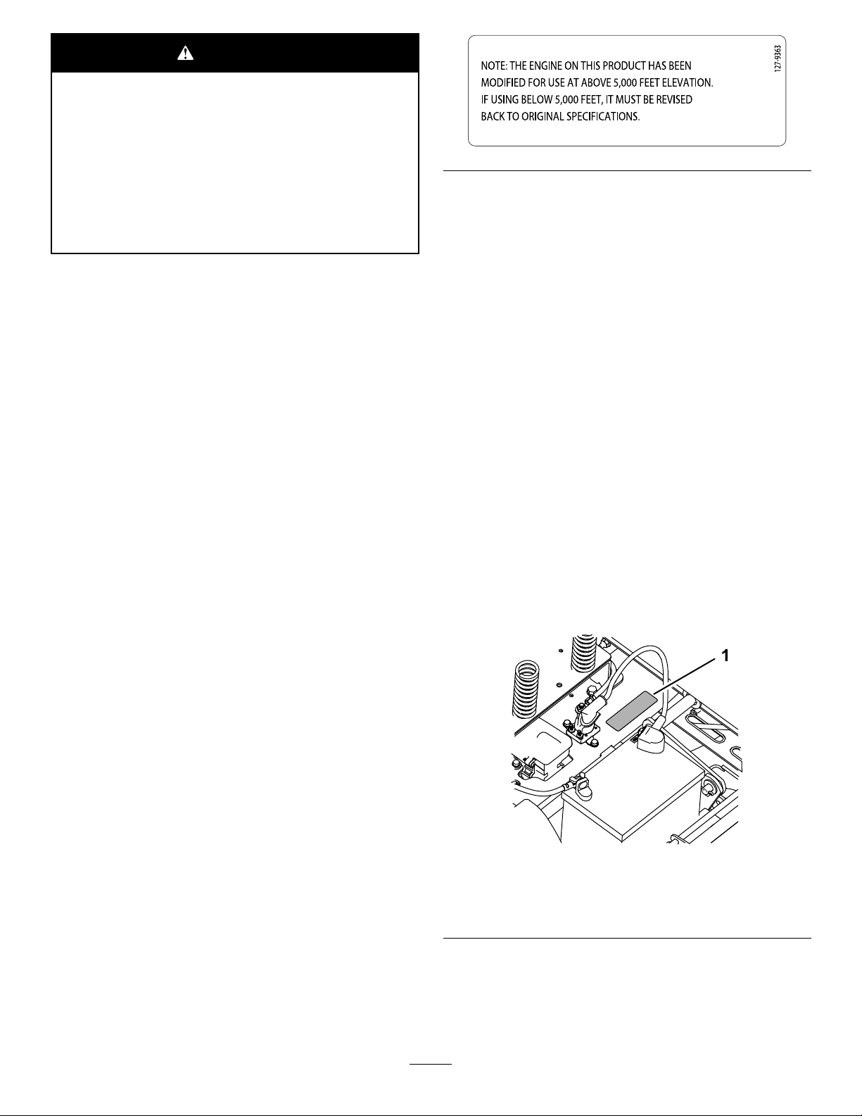
Ifyouareunsurewhetherornotyourmachinehasbeen
convertedforhigh-altitudeuse,lookforthefollowing
label.
decal127-9363
Introduction
Thismachineisaride-on,rotary-bladelawnmowerintended
tobeusedbyhomeownersinresidentialapplications.Itis
primarilydesignedforcuttinggrassonwell-maintainedlawns.
Itisnotdesignedforcuttingbrush,mowinggrassandother
growthalongsidehighways,orforagriculturaluses.
Readthisinformationcarefullytolearnhowtooperateand
maintainyourproductproperlyandtoavoidinjuryand
productdamage.Youareresponsibleforoperatingthe
productproperlyandsafely.
YoumaycontactTorodirectlyatwww .Toro.comforproduct
safetyandoperationtrainingmaterials,accessoryinformation,
helpndingadealer,ortoregisteryourproduct.
Wheneveryouneedservice,genuineT oroparts,oradditional
information,contactanAuthorizedServiceDealerorToro
CustomerServiceandhavethemodelandserialnumbersof
yourproductready.Figure1identiesthelocationofthe
modelandserialnumbersontheproduct.Writethenumbers
inthespaceprovided.
g188142
Figure1
Undertheseat
1.Modelandserialnumberplate
Writetheproductmodelandserialnumbersinthespace
below:
©2016—TheToro®Company
8111LyndaleAvenueSouth
Bloomington,MN55420
Contactusatwww.Toro.com.
2
PrintedintheUSA
AllRightsReserved
Page 3

ModelNo.
SerialNo.
Thismanualidentiespotentialhazardsandhassafety
messagesidentiedbythesafety-alertsymbol(Figure2),
whichsignalsahazardthatmaycauseseriousinjuryordeath
ifyoudonotfollowtherecommendedprecautions.
Figure2
1.Safety-alertsymbol.
Thismanualuses2wordstohighlightinformation.
Importantcallsattentiontospecialmechanicalinformation
andNoteemphasizesgeneralinformationworthyofspecial
attention.
Contents
Safety...........................................................................4
GeneralSafety.........................................................4
SlopeIndicator.......................................................5
SafetyandInstructionalDecals.................................6
ProductOverview.........................................................11
Controls...............................................................11
BeforeOperation......................................................13
BeforeOperationSafety..........................................13
RecommendedFuel................................................13
UsingStabilizer/Conditioner...................................14
FillingtheFuelTank...............................................14
g000502
CheckingtheEngine-OilLevel.................................14
BreakinginaNewMachine......................................14
ThinkSafetyFirst...................................................14
UsingtheSafety-InterlockSystem.............................15
PositioningtheSeat................................................16
AdjustingtheMotion-ControlLevers........................16
DuringOperation.....................................................17
DuringOperationSafety.........................................17
OperatingtheMowerBlade-ControlSwitch
(PTO)...............................................................18
OperatingtheThrottle............................................18
OperatingtheChoke...............................................18
OperatingtheIgnitionSwitch..................................19
StartingandShuttingOfftheEngine.........................19
UsingtheMotion-ControlLevers.............................20
DrivingtheMachine...............................................20
StoppingtheMachine.............................................21
AdjustingtheHeightofCut.....................................22
AdjustingtheAnti-ScalpRollers...............................22
UsingtheSideDischarge.........................................23
OperatingTips......................................................23
AfterOperation........................................................24
AfterOperationSafety............................................24
PushingtheMachinebyHand..................................24
TransportingtheMachine........................................25
LoadingtheMachine..............................................25
Maintenance.................................................................27
RecommendedMaintenanceSchedule(s)......................27
Pre-MaintenanceProcedures......................................28
MaintenanceandStorage.........................................28
RaisingtheSeat......................................................28
Lubrication...............................................................29
GreasingtheBearings.............................................29
EngineMaintenance..................................................29
EngineSafety.........................................................29
ServicingtheAirCleaner.........................................29
ServicingtheEngineOil..........................................30
ServicingtheSparkPlug..........................................33
CleaningtheCoolingSystem....................................34
FuelSystemMaintenance...........................................34
ReplacingtheIn-LineFuelFilter...............................34
ElectricalSystemMaintenance....................................35
ElectricalSystemSafety...........................................35
ServicingtheBattery...............................................35
ServicingtheFuses.................................................36
3
Page 4

DriveSystemMaintenance.........................................37
CheckingtheTirePressure......................................37
ReleasingtheElectricBrake.....................................38
MowerMaintenance...................................................38
ServicingtheCuttingBlades.....................................38
LevelingtheMowerDeck........................................40
RemovingtheMowerDeck.....................................42
ReplacingtheGrassDeector..................................43
MowerBeltMaintenance............................................45
InspectingtheBelts................................................45
ReplacingtheMower-DeckBelt...............................45
Cleaning...................................................................46
WashingtheUndersideoftheMower........................46
Storage........................................................................47
CleaningandStorage..............................................47
Troubleshooting...........................................................48
Schematics...................................................................50
Safety
ThismachinehasbeendesignedinaccordancewithANSI
B71.1-2012.
GeneralSafety
Thisproductiscapableofamputatinghandsandfeetand
ofthrowingobjects.Alwaysfollowallsafetyinstructionsto
avoidseriouspersonalinjury.
Usingthisproductforpurposesotherthanitsintendeduse
couldprovedangeroustoyouandbystanders.
•ReadandunderstandthecontentsofthisOperator’ sManual
beforeyoustarttheengine.Ensurethateveryoneusing
thisproductknowshowtouseitandunderstandsthe
warnings.
•Donotputyourhandsorfeetnearmovingcomponents
ofthemachine.
•Donotoperatethemachinewithoutallguardsandother
safetyprotectivedevicesinplaceandworkingonthe
machine.
•Keepclearofanydischargeopening.Keepbystandersa
safedistanceawayfromthemachine.
•Keepchildrenoutoftheoperatingarea.Neverallow
childrentooperatethemachine.
•Stopthemachineandshutofftheenginebeforeservicing,
fueling,oruncloggingthemachine.
Improperlyusingormaintainingthismachinecanresult
ininjury.Toreducethepotentialforinjury,complywith
thesesafetyinstructionsandalwayspayattentiontothe
safety-alertsymbol,whichmeansCaution,Warning,or
Danger—personalsafetyinstruction.Failuretocomplywith
theseinstructionsmayresultinpersonalinjuryordeath.
Youcanndadditionalitemsofsafetyinformationintheir
respectivesectionsthroughoutthismanual.
4
Page 5
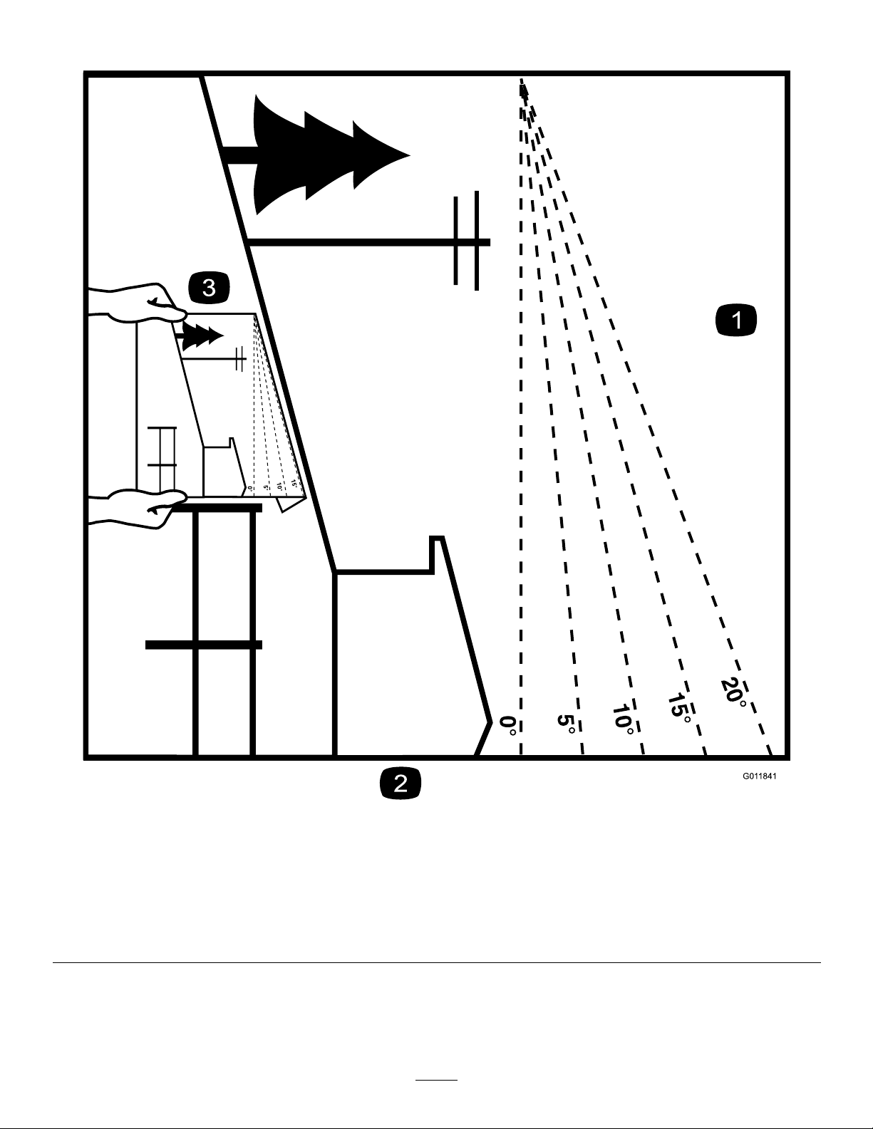
SlopeIndicator
G011841
Figure4
Thispagemaybecopiedforpersonaluse.
1.Themaximumslopeyoucansafelyoperatethemachineonis15degrees.Usetheslopecharttodeterminethedegreeofslope
ofhillsbeforeoperating.Donotoperatethismachineonaslopegreaterthan15degrees.Foldalongtheappropriateline
tomatchtherecommendedslope.
2.Alignthisedgewithaverticalsurface,atree,building,fencepole,etc.
3.Exampleofhowtocompareslopewithfoldededge
5
g011841
Page 6
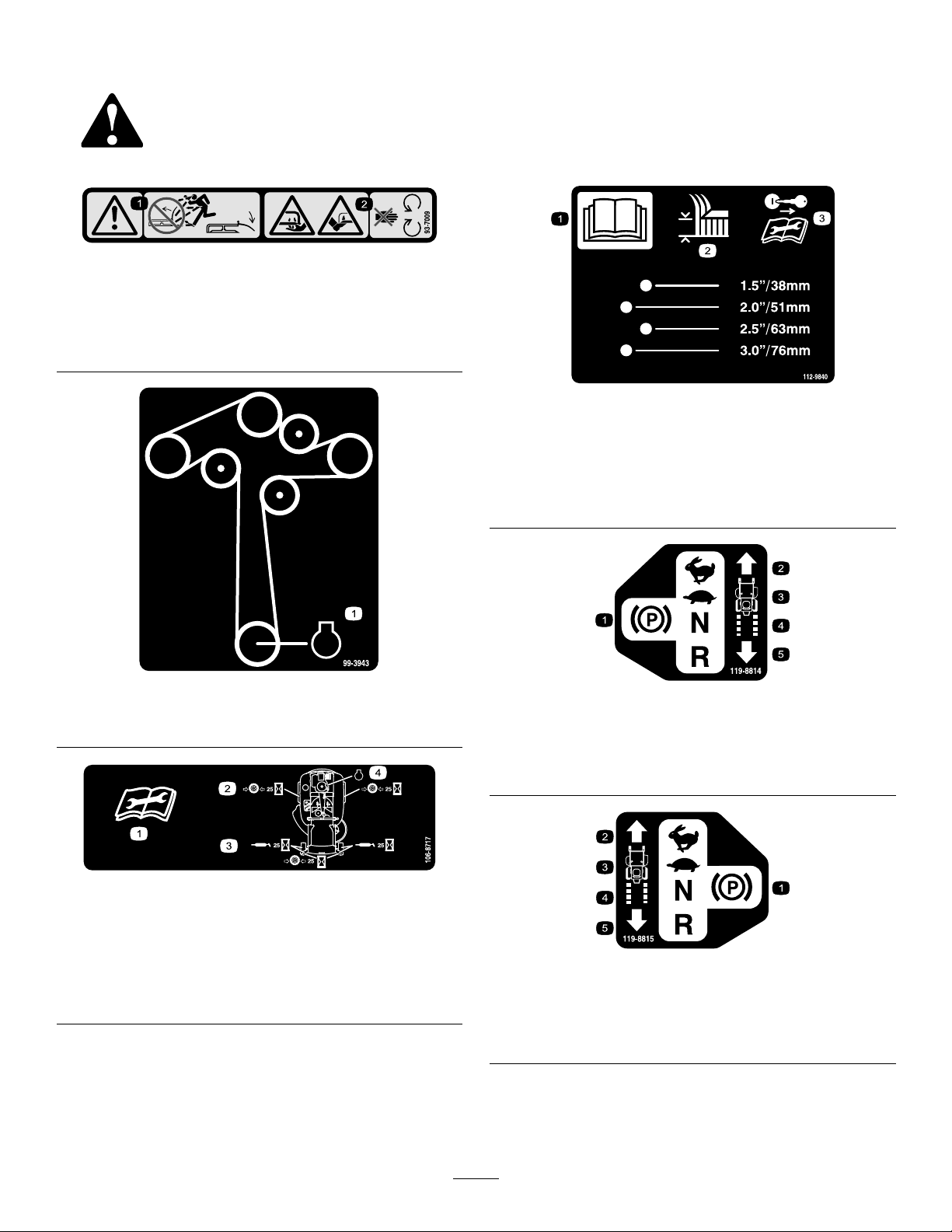
SafetyandInstructionalDecals
Safetydecalsandinstructionsareeasilyvisibletotheoperatorandarelocatednearanyareaofpotential
danger.Replaceanydecalthatisdamagedormissing.
93-7009
1.Warning—donotoperatethemowerwiththedeectorup
orremoved;keepthedeectorinplace.
2.Cutting/dismembermenthazardofhandorfoot,mower
blade—stayawayfrommovingparts.
decal93-7009
decal112-9840
112-9840
1.ReadtheOperator's
Manual.
3.Removetheignitionkey
andreadtheinstructions
beforeservicingor
performingmaintenance.
2.Heightofcut
decal99-3943
99-3943
1.Engine
1.Parkingposition4.Neutral
119-8814
decal119-8814
2.Fast5.Reverse
3.Slow
decal106-8717
106-8717
1.Readtheinstructionsbeforeservicingorperforming
maintenance.
2.Checktirepressureevery25operatinghours.
3.Greaseevery25operatinghours.
4.Engine
decal119-8815
119-8815
1.Parkingposition4.Neutral
2.Fast5.Reverse
3.Slow
6
Page 7
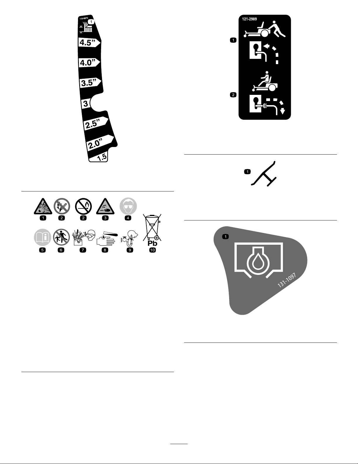
decal121-2989b
121-2989
119-8870
1.Heightofcut
BatterySymbols
Someorallofthesesymbolsareonyourbattery .
1.Explosionhazard
2.Nore,opename,or
smoking
3.Causticliquid/chemical
burnhazard
4.Weareyeprotection.9.Flusheyesimmediately
5.ReadtheOperator's
Manual.
6.Keepbystandersasafe
distanceawayfromthe
battery.
7.Weareyeprotection;
explosivegasescan
causeblindnessandother
injuries.
8.Batteryacidcancause
blindnessorsevereburns.
withwaterandgetmedical
helpfast.
10.Containslead;donot
discard.
1.Bypassleverpositionfor
pushingthemachine
decal119-8870
2.Bypassleverpositionfor
operatingthemachine
decaloemmarkt
Manufacturer'sMark
1.Indicatesthebladeisidentiedasapartfromtheoriginal
machinemanufacturer.
decalbatterysymbols
decal131-1097
131-1097
1.Oildrain
7
Page 8

decal132-0872
132-0872
1.Thrownobject
hazard—keepbystanders
awayfromthemachine.
2.Thrownobjecthazard,
raisedbafe—donot
operatethemachinewith
anopendeck;usea
baggerorabafe.
3.Severinghazardofhand
orfoot—keepawayfrom
movingparts.
4.Entanglement
hazard—keepaway
frommovingparts;keep
allguardsandshieldsin
place.
decal131-3947
131-3947
1.Trim—slow
3.Mow—fast
2.Tow—medium
8
Page 9
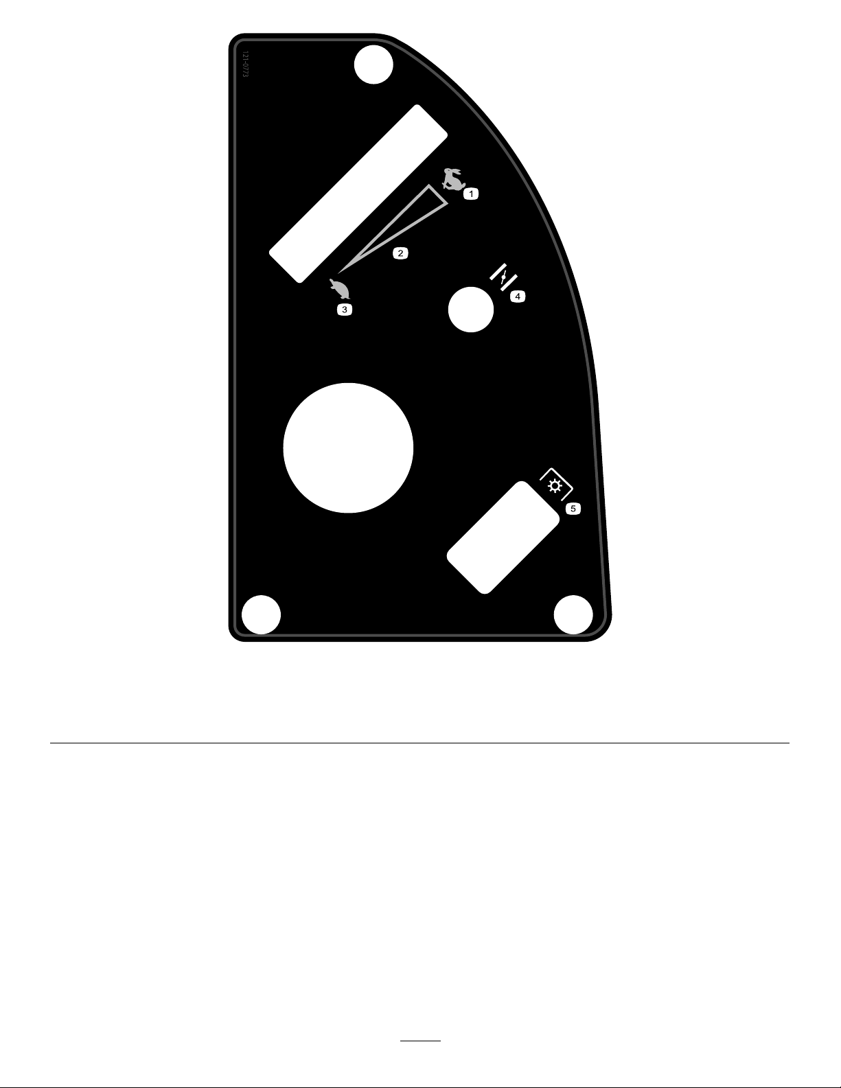
decal121-0773
121-0773
1.Fast
4.Choke
2.Continuous-variablesetting5.Powertakeoff(PTO),blade-controlswitch
3.Slow
9
Page 10
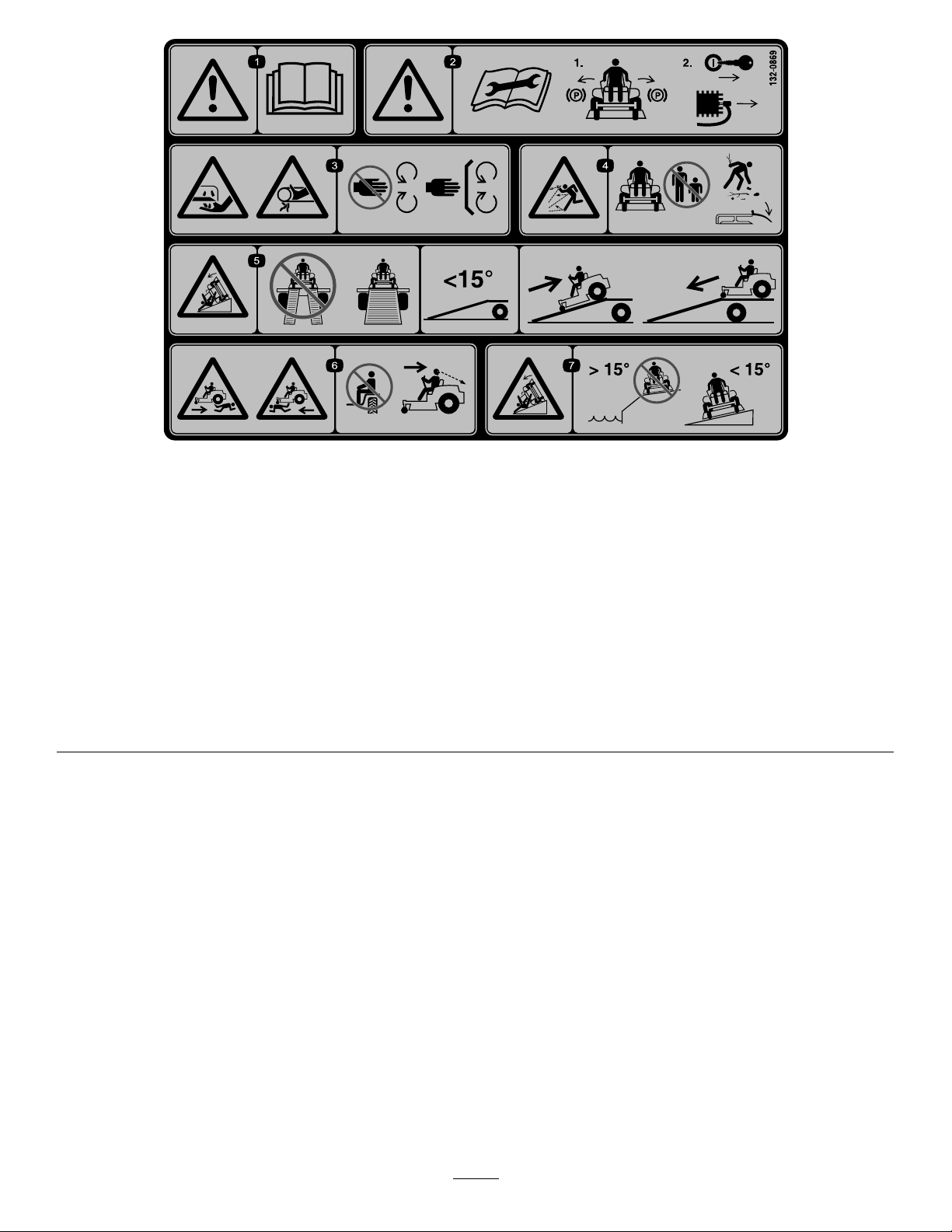
decal132-0869
132-0869
1.Warning—readthe
Operator'sManual.
2.Warning—beforeservicing,
engagetheparkingbrake,
removethekeyandthe
sparkplugconnection.
3.Cuttinghazardofhand,
mowerblade;pinching
hazardofhand,belt—keep
handsandfeetawayfrom
movingparts;keepall
guardsandshieldsinplace.
4.Thrownobject
hazard—keepbystanders
awayfromthemachine;
removedebrisfromthe
areabeforemowing;keep
thedeectorshielddown.
5.Ramptipping
hazard—whenloading
ontoatrailer,donotuse
dualramps;onlyusea
singlerampwideenough
forthemachineandthat
hasaninclinelessthan
15degrees;backupthe
ramp(inreverse)anddrive
forwardofftheramp.
6.Bodilyharmhazard—no
riders;lookbehindyou
whenmowinginreverse.
7.Tippinghazardon
slopes—donotuseon
slopesnearopenwater;do
notuseonslopesgreater
than15degrees.
10
Page 11
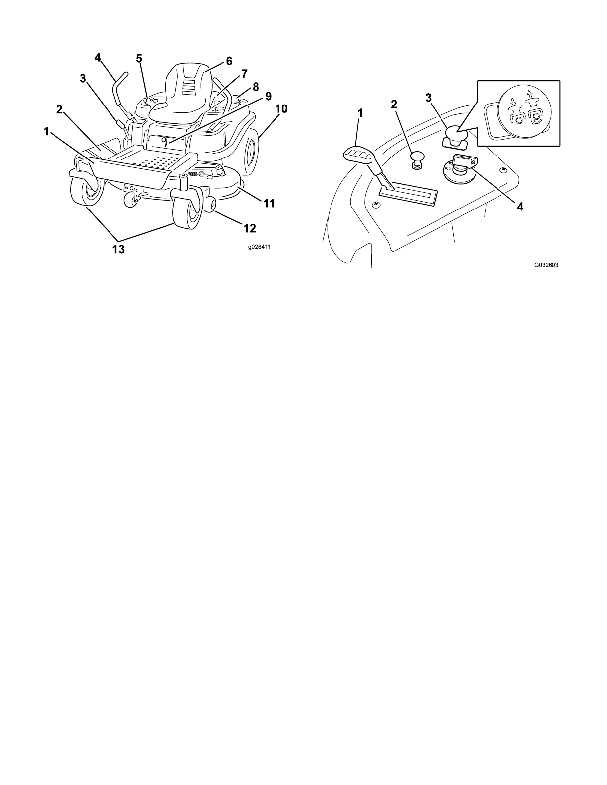
ProductOverview
Figure5
1.Footrest
2.Deector9.SmartSpeed™lever
3.Height-of-cutlever
4.Motion-controllever11.Mowerdeck
5.Controlpanel
6.Operatorseat
7.Engine
8.Gas-tankcap
10.Reardrivewheel
12.Anti-scalproller
13.Frontcasterwheel
Controls
BecomefamiliarwithallofthecontrolsinFigure5and
Figure6beforeyoustarttheengineandoperatethemachine.
g028411
g032603
Figure6
Controlpanel
1.Throttle3.Blade-controlswitch
2.Choke
(powertakeoff)
4.Ignitionswitch
IgnitionSwitch
Usethisswitchtostartthemowerengine.Ithas3positions:
START,RUN,andOFF.
ChokeControl
Usethechoketostartacoldengine.Pullthechokeknob
uptoengageit.Pushthechokeknobdowntodisengage
it(Figure7).
ThrottleControl
Thethrottlecontrolstheenginespeed,andithasa
continuous-variablesettingfromtheSLOWtoFASTposition
(Figure7).
Blade-ControlSwitch(PowerTakeoff)
Theblade-controlswitch,representedbyapower-takeoff
(PTO)symbol,engagesanddisengagespowertothemower
blades(Figure6).
11
Page 12
Motion-ControlLevers
G014521
1
Height-of-CutLever
Usethemotion-controlleverstodrivethemachineforward,
reverse,andturneitherdirection.
ParkPosition
Movethemotion-controlleversoutwardfromthecenterto
thePARKpositionwhenexitingthemachine(Figure20).
Alwayspositionthemotion-controlleversintothePARK
positionwhenyoustopthemachineorleaveitunattended.
SmartSpeed™ControlSystemLever
TheSmartSpeed™Control-Systemlever,locatedbelowthe
operatingposition,givesyouachoicetodrivethemachineat
3speedranges—trim,tow ,andmow(Figure23).
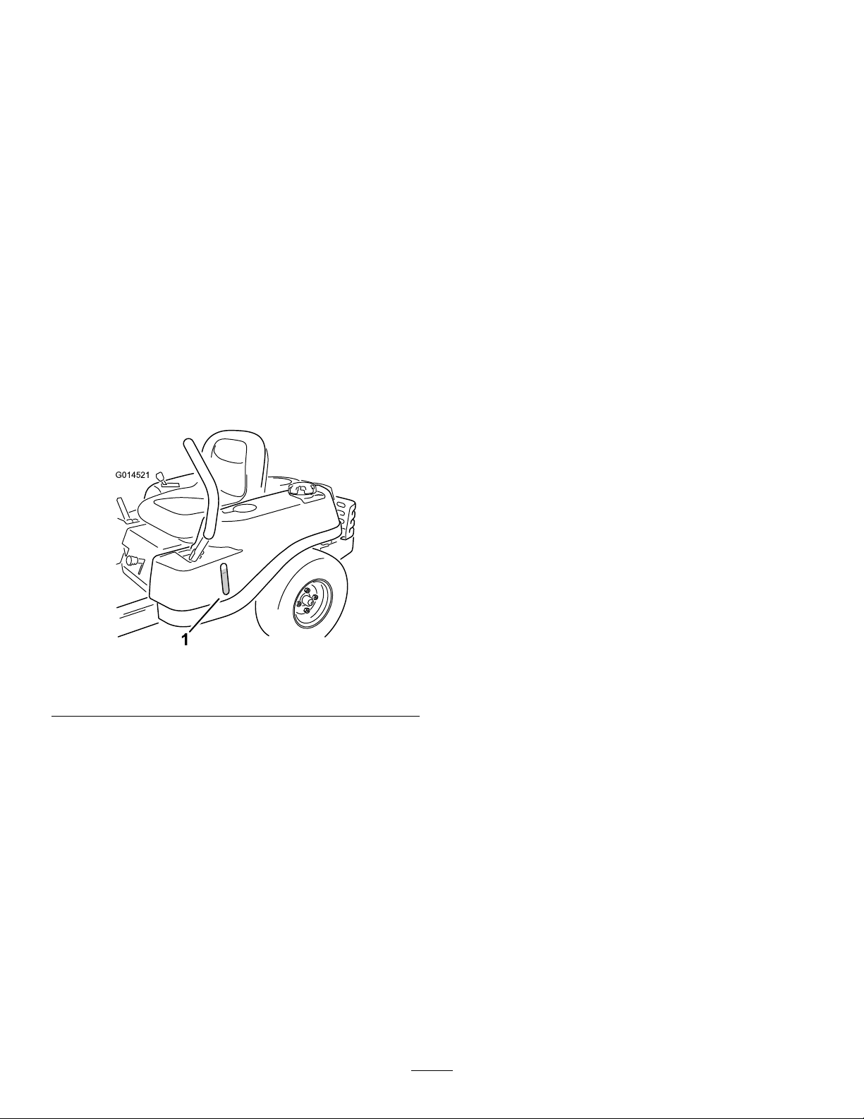
Fuel-PresenceWindow
Youcanusethefuelwindow ,locatedontheleftsideofthe
machine,toverifythepresenceoffuelinthetank(Figure7).
Usetheheight-of-cutlevertolowerandraisethedeckfrom
theseatedposition.Movingtheleverup(towardyou)raises
thedeckfromthegroundandmovingtheleverdown(away
fromyou)lowersthedecktowardtheground.Adjustthe
height-of-cutonlywhilethemachineisnotmoving(Figure
24).
Attachments/Accessories
AselectionofToroapprovedattachmentsandaccessoriesis
availableforusewiththemachinetoenhanceandexpand
itscapabilities.ContactyourAuthorizedServiceDealeror
Distributororgotowww .Toro.comforalistofallapproved
attachmentsandaccessories.
g014521
Figure7
1.Fuel-presencewindow
12
Page 13

Operation
thenrefuelfromaportablecontainerratherthana
fuel-dispensernozzle.
Note:Determinetheleftandrightsidesofthemachine
fromthenormaloperatingposition.
BeforeOperation
BeforeOperationSafety
GeneralSafety
•Neverallowchildrenoruntrainedpeopletooperateor
servicethemachine.Localregulationsmayrestrictthe
ageoftheoperator.Theownerisresponsiblefortraining
alloperatorsandmechanics.
•Becomefamiliarwiththesafeoperationoftheequipment,
operatorcontrols,andsafetysigns.
•Knowhowtostopthemachineandenginequickly.
•Checkthatoperator-presencecontrols,safetyswitches,
andshieldsareattachedandfunctioningproperly.Donot
operatethemachineunlesstheyarefunctioningproperly.
•Beforemowing,alwaysinspectthemachinetoensurethat
theblades,bladebolts,andcuttingassembliesareingood
workingcondition.Replacewornordamagedbladesand
boltsinsetstopreservebalance.
•Inspecttheareawhereyouwillusethemachineand
removeallobjectsthatthemachinecouldthrow.
•Evaluatetheterraintodeterminetheappropriate
equipmentandanyattachmentsoraccessoriesrequiredto
operatethemachineproperlyandsafely.
FuelSafety
•Toavoidpersonalinjuryorpropertydamage,useextreme
careinhandlingfuel.Fuelvaporsareammableand
explosive.
•Extinguishallcigarettes,cigars,pipes,andothersources
ofignition.
•Useonlyanapprovedfuelcontainer.
•Donotremovethefuelcaporaddfueltothefueltank
whiletheengineisrunningorwhilehot.
•Donotrefuelthemachineindoors.
•Donotstorethemachineorfuelcontainerwherethere
isanopename,spark,orpilotlight,suchasonawater
heateroronotherappliances.
•Donotoperatethemachinewithouttheentireexhaust
systeminplaceandinproperworkingcondition.
•Keepthefuel-dispensernozzleincontactwiththerimof
thefueltankorcontaineropeningatalltimesuntilfueling
iscomplete.Donotuseanozzlelock-opendevice.
•Ifyouspillfuelonyourclothing,changeyourclothing
immediately.Wipeupanyfuelthatspills.
•Neveroverllthefueltank.Replacethefuelcapand
tightenitsecurely.
•Storefuelinanapprovedcontainerandkeepitoutofthe
reachofchildren.Neverbuymorethana30-daysupply
offuel.
•Donotllthefueltankcompletelyfull.Addfueltothe
fueltankuntilthelevelis6to13mm(1/4to1/2inch)
belowthebottomofthellerneck.Thisemptyspacein
thetankallowsfueltoexpand.
–Avoidprolongedbreathingofvapors.
–Keepyourfaceawayfromthenozzleandgastank
opening.
–Avoidcontactwithskin;washoffspillswithsoapand
water.
RecommendedFuel
•Forbestresults,useonlyclean,fresh(lessthan30days
old),unleadedgasolinewithanoctaneratingof87or
higher((R+M)/2ratingmethod).
•Ethanol:Gasolinewithupto10%ethanol(gasohol)
or15%MTBE(methyltertiarybutylether)byvolume
isacceptable.EthanolandMTBEarenotthesame.
Gasolinewith15%ethanol(E15)byvolumeisnot
approvedforuse.Neverusegasolinethatcontains
morethan10%ethanolbyvolume,suchasE15
(contains15%ethanol),E20(contains20%ethanol),or
E85(containsupto85%ethanol).Usingunapproved
gasolinemaycauseperformanceproblemsand/orengine
damagewhichmaynotbecoveredunderwarranty.
•Donotusegasolinecontainingmethanol.
•Donotstorefueleitherinthefueltankorfuelcontainers
overthewinterunlessyouuseafuelstabilizer.
•Donotaddoiltogasoline.
•Donotllcontainersinsideavehicleoronatruckor
trailerbedwithaplasticliner.Alwaysplacecontainerson
theground,awayfromyourvehiclebeforelling.
•Removetheequipmentfromthetruckortrailerand
refuelitwhileitisontheground.Ifthisisnotpossible,
13
Page 14
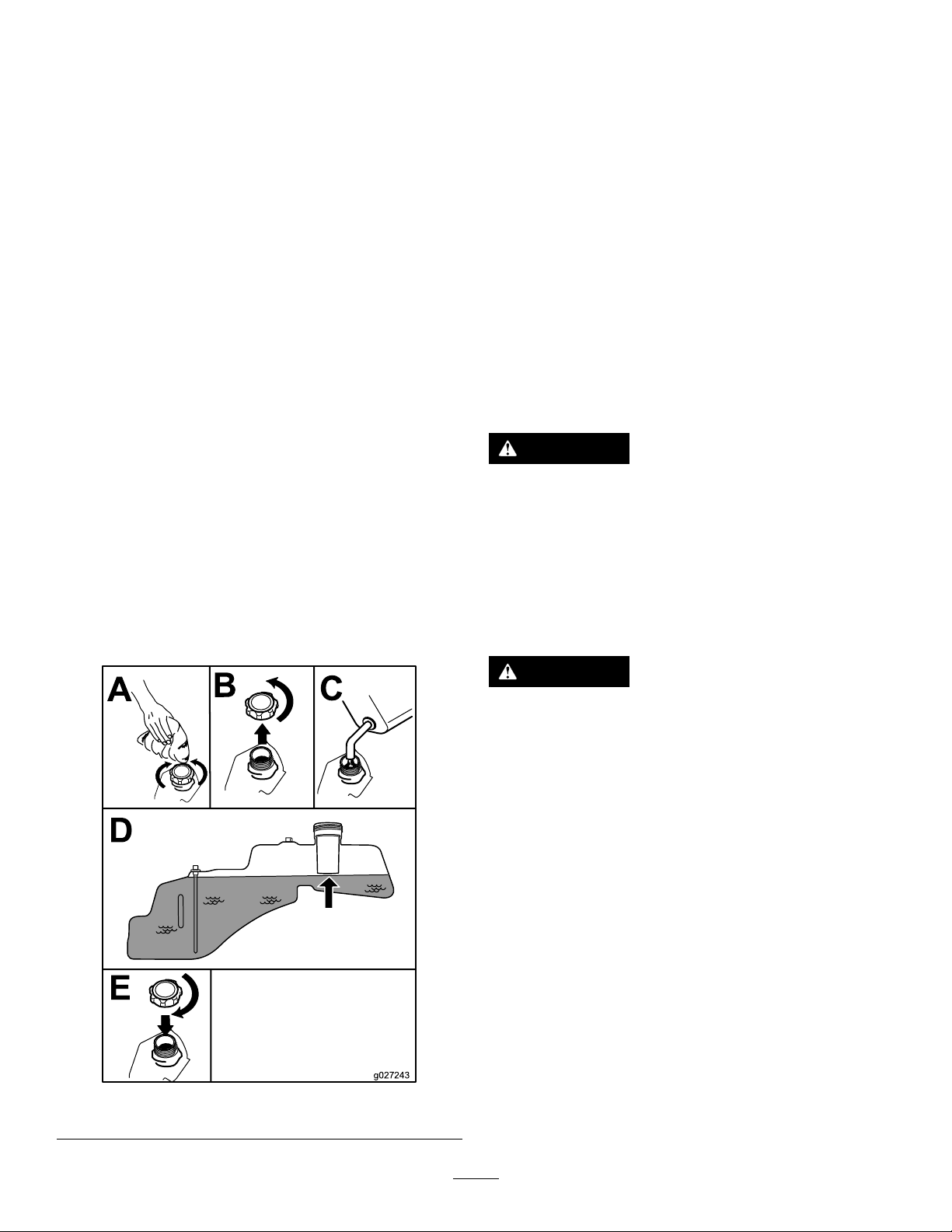
UsingStabilizer/Conditioner
g027243
A
B
E
D
C
CheckingtheEngine-OilLevel
Useafuelstabilizer/conditionerinthemachinetoprovide
thefollowingbenets:
•Keepsfuelfreshduringstorageof90daysorless(drain
thefueltankwhenstoringthemachineformorethan
90days)
•Cleanstheenginewhileitruns
•Eliminatesgum-likevarnishbuildupinthefuelsystem,
whichcauseshardstarting
Important:Donotusefueladditivescontaining
methanolorethanol.
Addthecorrectamountoffuelstabilizer/conditioner
tothefuel.
Note:Afuelstabilizer/conditionerismosteffective
whenmixedwithfreshfuel.T ominimizethechanceof
varnishdepositsinthefuelsystem,usefuelstabilizerat
alltimes.
FillingtheFuelTank
1.Parkthemachineonlevelground.
2.Shutofftheengineandengagetheparkingbrake.
3.Cleanaroundthefuel-tankcap.
4.Fillthefueltanktothebottomofthellerneck(Figure
8).
Note:Donotllthefueltankcompletelyfull.The
emptyspaceinthetankallowsthefueltoexpand.
Beforeyoustarttheengineandusethemachine,check
theoillevelintheenginecrankcase;refertoCheckingthe
Engine-OilLevel(page30).
BreakinginaNewMachine
Newenginestaketimetodevelopfullpower.Mowerdecks
anddrivesystemshavehigherfrictionwhennew,placing
additionalloadontheengine.Allow40to50hoursof
break-intimefornewmachinestodevelopfullpowerand
bestperformance.
ThinkSafetyFirst
Pleasereadallsafetyinstructionsandsymbolsinthesafety
section.Knowingthisinformationcouldhelpyouor
bystandersavoidinjury.
DANGER
Operatingthemachineonwetgrassorsteepslopes
cancauseslidingandlossofcontrol.
•Donotoperateonslopesgreaterthan15degrees.
•Reducespeedanduseextremecautionon
slopes.
•Donotoperatethemachinenearwater.
DANGER
Wheelsdroppingoveredgescancauserollovers,
whichmayresultinseriousinjury,death,or
drowning.
Donotoperatethemachineneardrop-offs.
g027243
Figure8
14
Page 15
G009027
1
2
UsingtheSafety-Interlock System
WARNING
Ifthesafety-interlockswitchesaredisconnectedor
damaged,themachinecouldoperateunexpectedly,
causingpersonalinjury.
•Donottamperwiththeinterlockswitches.
•Checktheoperationoftheinterlockswitches
dailyandreplaceanydamagedswitchesbefore
operatingthemachine.
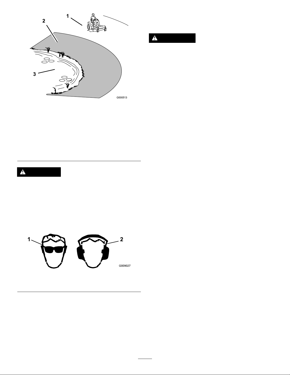
Figure9
1.SafeZone—usethe
machinehereonslopes
lessthan15degreesor
atareas.
2.DangerZone—usea
walk-behindmowerand/or
ahandtrimmeronslopes
greaterthan15degrees,
neardrop-offsandwater.
3.Water
CAUTION
Thismachineproducessoundlevelsinexcessof
85dBAattheoperator’searandcancausehearing
lossthroughextendedperiodsofexposure.
Wearhearingprotectionwhenoperatingthis
machine.
Useprotectiveequipmentforyoureyes,ears,hands,feet,
andhead.
g000513
UnderstandingtheSafety-Interlock
System
Thesafety-interlocksystemisdesignedtopreventtheengine
fromstartingunless:
•Theblade-controlswitch(PTO)isdisengaged.
•Themotion-controlleversareinthePARKposition.
Thesafety-interlocksystemalsoisdesignedtoshutoffthe
enginewheneverthecontrolleversareoutofthePARK
positionandyourisefromtheseat.
TestingtheSafety-InterlockSystem
Testthesafety-interlocksystembeforeyouusethemachine
eachtime.Ifthesafetysystemdoesnotoperateasdescribed
below,haveanAuthorizedServiceDealerrepairthesafety
systemimmediately.
1.Sitontheseat,movethemotion-controlleversinthe
PARKposition,andmovetheblade-controlswitchto
theONposition.Trystartingtheengine;theengine
shouldnotcrank.
2.Sitontheseatandmovetheblade-controlswitchto
theOFFposition.Moveeithermotion-controlleverto
thecenter,unlockedposition.Trystartingtheengine;
theengineshouldnotcrank.Repeatwiththeother
motion-controllever.
g009027
Figure10
1.Weareyeprotection.2.Wearhearingprotection.
3.Sitontheseat,movetheblade-controlswitchtothe
OFFposition,andlockthemotion-controlleversin
thePARKposition.Starttheengine.Whiletheengine
isrunning,engagetheblade-controlswitch,andrise
slightlyfromtheseat;theengineshouldshutoff.
4.Sitontheseat,movetheblade-controlswitchtothe
OFFposition,andlockthemotion-controlleversinthe
PARKposition.Starttheengine.Whiletheengineis
running,movethemotion-controlleverstothecenter,
unlockedposition,engagetheblade-controlswitch,and
riseslightlyfromtheseat;theengineshouldshutoff.
15
Page 16
PositioningtheSeat
g027252
B
A
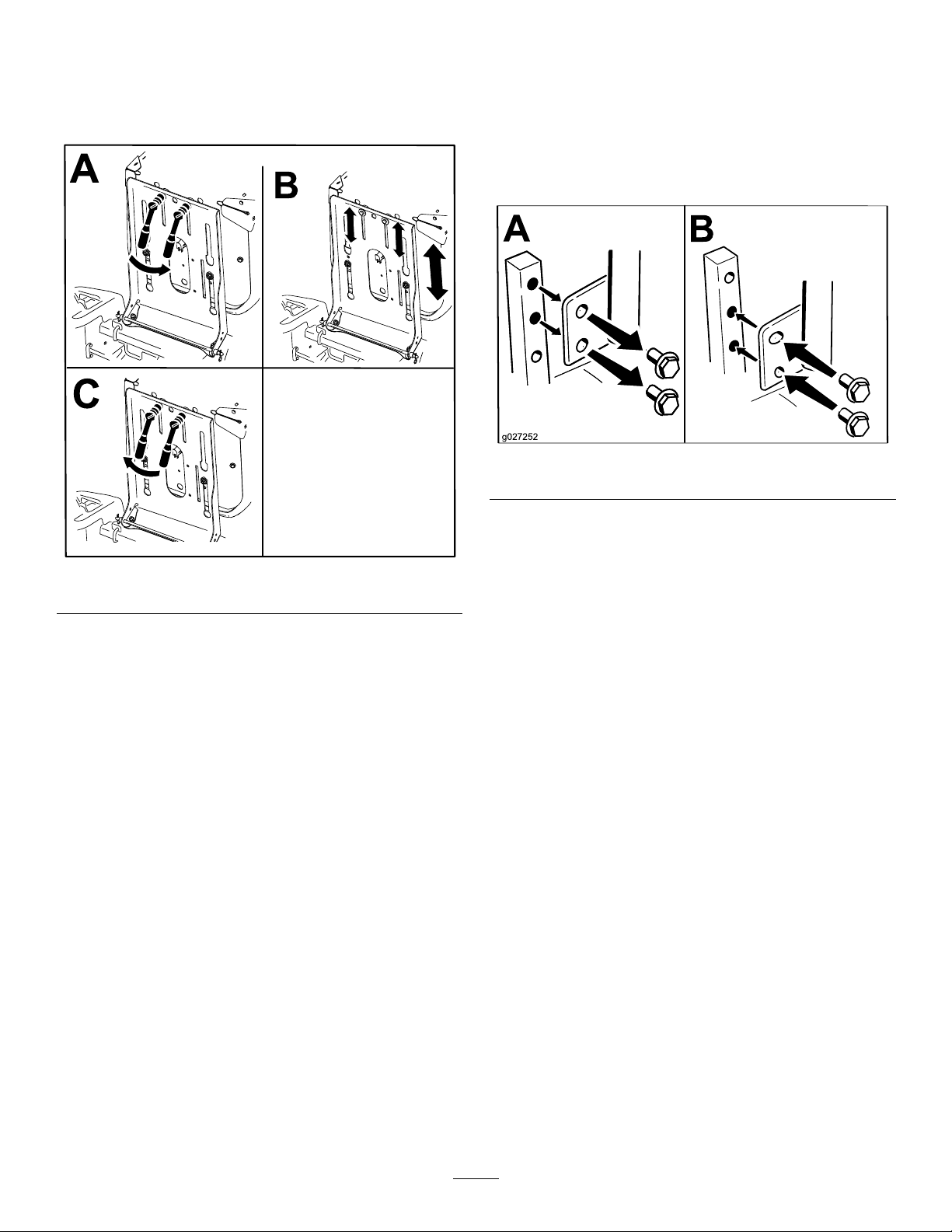
AdjustingtheMotion-Control
Theseatcanmoveforwardandbackward.Positiontheseat
whereyouhavethebestcontrolofthemachineandaremost
comfortable(Figure11).
Levers
AdjustingtheHeight
Youcanadjustthemotion-controllevershigherorlowerfor
maximumcomfort(Figure12).
g027252
Figure12
Figure11
AdjustingtheTilt
g188217
Youcanadjustthemotion-controlleversforwardorrearward
foryourcomfort.
1.Loosentheupperboltholdingthecontrollevertothe
control-armshaft.
2.Loosenthelowerboltjustenoughtopivotthecontrol
leverforwardorrearward(Figure12).
3.Tightenbothboltstosecurethecontrolleverinthe
newposition.
4.Repeattheadjustmentfortheothercontrollever.
16
Page 17

DuringOperation
DuringOperationSafety
–Disengagethepowertake-offandlowerthe
attachments.
–Engagetheparkingbrake.
–Shutofftheengineandremovethekey .
GeneralSafety
•Theowner/operatorcanpreventandisresponsiblefor
accidentsthatmaycausepersonalinjuryorproperty
damage.
•Wearappropriateclothing,includingeyeprotection;
slip-resistant,substantialfootwear;andhearing
protection.Tiebacklonghairanddonotwearjewelry.
•Donotoperatethemachinewhileill,tired,orunderthe
inuenceofalcoholordrugs.
•Nevercarrypassengersonthemachineandkeep
bystandersandpetsawayfromthemachineduring
operation.
•Operatethemachineonlyingoodvisibilitytoavoidholes
orhiddenhazards.
•Avoidmowingonwetgrass.Reducedtractioncould
causethemachinetoslide.
•Ensurethatalldrivesareinneutral,theparkingbrake
isengaged,andyouareintheoperatingpositionbefore
youstarttheengine.
•Keepyourhandsandfeetawayfromthecuttingunits.
Keepclearofthedischargeopeningatalltimes.
–Waitforallmovingpartstostop.
•Donotoperatethemachinewhenthereistheriskof
lightning.
•Donotusethemachineasatowingvehicle.
•Donotchangethegovernorspeedoroverspeedthe
engine.
•UseaccessoriesandattachmentsapprovedbyToroonly.
SlopeSafety
•Slowdownthemachineanduseextracareonhillsides.
Travelupanddownonhillsides.Turfconditionscan
affectthestabilityofthemachine.
•Avoidturningthemachineonslopes.Ifyoumustturnthe
machine,turnitslowlyandgraduallydownhill,ifpossible.
•Donotturnthemachinesharply .Usecarewhenreversing
themachine.
•Useextracarewhileoperatingthemachinewith
attachments;theycanaffectthestabilityofthemachine.
•Lookbehindanddownbeforebackinguptobesureof
aclearpath.
•Usecarewhenapproachingblindcorners,shrubs,trees,
orotherobjectsthatmayobscureyourvision.
•Donotmowneardrop-offs,ditches,orembankments.
Themachinecouldsuddenlyrolloverifawheelgoes
overtheedgeoriftheedgegivesway.
•Stopthebladeswheneveryouarenotmowing.
•Stopthemachineandinspectthebladesafterstrikingan
objectorifthereisanabnormalvibrationinthemachine.
Makeallnecessaryrepairsbeforeresumingoperation.
•Slowdownandusecautionwhenmakingturnsand
crossingroadsandsidewalkswiththemachine.Always
yieldtheright-of-way.
•Disengagethedrivetothecuttingunitandshutoffthe
enginebeforeadjustingtheheightofcut(unlessyoucan
adjustitfromtheoperatingposition).
•Neverrunanengineinanareawhereexhaustgasesare
enclosed.
•Neverleavearunningmachineunattended.
•Beforeleavingtheoperatingposition(includingtoempty
thecatchersortounclogthechute),dothefollowing:
–Stopthemachineonlevelground.
17
Page 18

OperatingtheMower
G008945
G009174
G008959
1
2
OperatingtheThrottle
Blade-ControlSwitch(PTO)
Theblade-controlswitch(PTO)startsandstopsthemower
bladesandanypoweredattachments.
EngagingtheBlade-ControlSwitch
(PTO)
Figure13
Note:AlwaysengagethebladeswiththethrottleintheFAST
position(Figure14).
YoucanmovethethrottlecontrolbetweentheFASTand
SLOWpositions(Figure16).
AlwaysusetheFASTpositionwhenturningonthemower
deckwiththeblade-controlswitch(PTO).
g187517
g008945
Figure16
OperatingtheChoke
Usethechoketostartacoldengine.
1.Iftheengineiscold,usethechoketostarttheengine.
2.Pullupthechokeknobtoengagethechokebefore
usingtheignitionswitch(Figure17).
Note:Ensurethatyoufullyengagethechoke.You
mayneedtoholdtheknobupwhenyouusethe
ignitionswitch.
3.Pushdownthechoketodisengagethechokeafterthe
enginehasstarted(Figure17).
g187516
Figure14
DisengagingtheBlade-ControlSwitch
(PTO)
g009174
Figure15
Figure17
g008959
1.Onposition2.Offposition
18
Page 19

OperatingtheIgnitionSwitch
START
RUN
STOP
G008947
g027581
B
C
D
E
A
G
F
1.TurntheignitionkeytotheSTARTposition(Figure18).
Note:Whentheenginestarts,releasethekey.
Important:Donotengagethestarterformore
than5secondsatatime.Iftheenginefailsto
start,wait15secondsbetweenattempts.Failureto
followtheseinstructionscanburnoutthestarter
motor.
Note:Youmayneedmultipleattemptstostartthe
enginewhenyoustartitthersttimeafterthefuel
systemhasbeenwithoutfuelcompletely.
Figure18
g008947
2.TurntheignitionkeytotheSTOPpositiontoshutoff
theengine.
StartingandShuttingOffthe Engine
StartingtheEngine
Note:Awarmorhotenginemaynotrequirechoking.
Important:Donotengagethestarterformorethan
5secondsatatime.Engagingthestartermotorfor
morethan5secondscandamagethestartermotor.If
theenginefailstostart,wait10secondsbeforeoperating
theenginestarteragain.
g027581
Figure19
ShuttingOfftheEngine
1.Disengagethebladesbymovingtheblade-control
switchtotheOFFposition(Figure17).
2.MovethethrottlelevertotheFASTposition.
3.TurntheignitionkeytotheOFFpositionandremove
thekey.
19
Page 20

UsingtheMotion-Control
G008952
G008953
Levers
DrivingForward
Note:Alwaysusecautionwhenbackingupandturning.
1.Movetheleverstothecenter,unlockedposition.
2.Togoforward,slowlypushthemotion-controllevers
forward(Figure21).
Figure20
1.Motion-control
lever—PARKposition
2.Center,unlockedposition5.Frontofmachine
3.Forward
4.Backward
DrivingtheMachine
Thedrivewheelsturnindependently,poweredbyhydraulic
motorsoneachaxle.Youcanturn1sideinreversewhileyou
turntheotherforward,causingthemachinetospinrather
thanturn.Thisgreatlyimprovesthemachinemaneuverability
butmayrequiresometimeforyoutoadapttohowitmoves.
Thethrottlecontrolregulatestheenginespeedasmeasured
inrpm(revolutionsperminute).Placethethrottlecontrolin
theFASTpositionforbestperformance.Alwaysoperatein
thefullthrottlepositionwhenmowing.
g008952
Figure21
g004532
DrivingBackward
1.Movetheleverstothecenter,unlockedposition.
2.Togobackward,slowlypullthemotion-controllevers
rearward(Figure22).
WARNING
Themachinecanspinveryrapidly.Y oumaylose
controlofthemachineandcausepersonalinjuryor
damagetothemachine.
•Usecautionwhenmakingturns.
•Slowthemachinedownbeforemakingsharp
turns.
g008953
Figure22
20
Page 21

UsingtheSmartSpeed
TM
Control
System
TheSmartSpeed
operatingposition(Figure23),givestheoperatorachoice
todrivethemachineat3groundspeedranges—trim,tow ,
andmow .
1.Smart-speedlever
TM
Control-Systemlever,locatedbelowthe
Figure23
Tow
Thisisthemediumspeed.Thesuggestedusesforthisspeed
areasfollows:
•Bagging
•Mulching
Mow
Thisisthefastestspeed.Thesuggestedusesforthisspeed
areasfollows:
•Normalmowing
•Transportingthemachine
StoppingtheMachine
Tostopthemachine,movethemotion-controlleversto
g027625
NEUTRALandoutwardtothePARKposition,disengagethe
blade-controlswitch,ensurethatthethrottleisintheFAST
position,andturntheignitionkeytoOFF.Removethekey
fromtheignitionswitch.
Tochangespeeds,dothefollowing:
1.Movethemotion-controlleverstoneutralandoutward
tothePARKposition.
2.Disengagetheblade-controlswitch.
3.Adjustthelevertothedesiredposition.
Thefollowingareonlyrecommendationsforuse.
Adjustmentsvarybygrasstype,moisturecontent,andthe
heightofthegrass.
Suggested
uses:
ParkingX
Heavy,wet
grass
TrainingX
BaggingX
MulchingX
Normal
mowing
TransportX
TrimTowMow
X
X
WARNING
Childrenorbystandersmaybeinjuredifthey
moveorattempttooperatethemowerwhileitis
unattended.
Alwaysremovetheignitionkeyandmovethe
motion-controlleversoutwardtothePARKposition
whenleavingthemachineunattended,evenifjust
forafewminutes.
Trim
Thisisthelowestspeed.Thesuggestedusesforthisspeed
areasfollows:
•Parking
•Heavy,wetgrassmowingconditions
•Training
21
Page 22

AdjustingtheHeightofCut
G010233
1
2
3
4
AdjustingtheAnti-Scalp
Note:Thetransportpositionisthehighestheight-of-cut
positionat115mm(4-1/2inches)asshowninFigure24.
Rollers
Wheneveryouchangetheheightofcut,adjusttheheight
oftheanti-scalprollers.
Note:Adjusttheanti-scalprollerssotherollersdonottouch
thegroundinnormal,atmowingareas.
1.Parkthemachineonalevelsurfaceanddisengagethe
blade-controlswitch.
2.Ensurethattheparkingbrakeisengaged,shutoffthe
engine,removethekey,andwaitforallmovingpartsto
stopbeforeleavingtheoperatingposition.
3.Adjusttheanti-scalprollers(Figure25)tomatchthe
closestheight-of-cutposition.
g010233
Figure25
1.Anti-scalproller3.Flangenut
g027504
Figure24
2.Bolt4.Holespacing
22
Page 23

UsingtheSideDischarge
MowingatCorrectIntervals
Themowerhasahingedgrassdeectorthatdisperses
clippingstothesideanddowntowardtheturf.
DANGER
Withoutagrassdeector,dischargecover,ora
completegrass-catcherassemblymountedin
place,youandothersareexposedtobladecontact
andthrowndebris.Contactwithrotatingmower
blade(s)andthrowndebriswillcauseinjuryor
death.
•Neverremovethegrassdeectorfromthemower
becausethegrassdeectorroutesmaterialdown
towardtheturf.Ifthegrassdeectorisever
damaged,replaceitimmediately .
•Neverputyourhandsorfeetunderthemower.
•Nevertrytoclearthedischargeareaormower
bladesunlessyoumovetheblade-controlswitch
(PTO)totheOFFposition,rotatetheignition
keytotheOFFposition,andremovethekey.
•Makesurethatthegrassdeectorisinthedown
position.
Grassgrowsatdifferentratesatdifferenttimesoftheyear.
Tomaintainthesamecuttingheight,mowmoreofteninearly
spring.Asthegrassgrowthrateslowsinmidsummer,mow
lessfrequently .Ifyoucannotmowforanextendedperiod,
rstmowatahighcuttingheight,thenmowagain2days
lateratalowerheightsetting.
UsingaSlowerCuttingSpeed
Toimprovecutquality,useaslowergroundspeedincertain
conditions.
AvoidingCuttingTooLow
Whenmowinguneventurf,raisethecuttingheighttoavoid
scalpingtheturf.
StoppingtheMachine
Ifyoumuststoptheforwardmotionofthemachinewhile
mowing,aclumpofgrassclippingsmaydropontoyour
lawn.Toavoidthis,moveontoapreviouslycutareawiththe
bladesengagedoryoucandisengagethemowerdeckwhile
movingforward.
OperatingTips
UsingtheFastThrottleSetting
Forbestmowingandmaximumaircirculation,operatethe
engineattheFASTposition.Airisrequiredtothoroughlycut
grassclippings,sodonotsettheheight-of-cutsolowasto
totallysurroundthemowerinuncutgrass.Alwaystrytohave
1sideofthemowerfreefromuncutgrass,whichallowsair
tobedrawnintothemower.
CuttingaLawnfortheFirstTime
Cutgrassslightlylongerthannormaltoensurethatthe
cuttingheightofthemowerdoesnotscalpanyuneven
ground.However,thecuttingheightusedinthepastis
generallythebestonetouse.Whencuttinggrasslongerthan
15cm(6inches)tall,youmaywanttocutthelawntwiceto
ensureanacceptablequalityofcut.
CuttingaThirdoftheGrassBlade
Itisbesttocutonlyaboutathirdofthegrassblade.Cutting
morethanthatisnotrecommendedunlessgrassissparse,or
itislatefallwhengrassgrowsmoreslowly.
KeepingtheUndersideoftheMower
Clean
Cleanclippingsanddirtfromtheundersideofthemower
aftereachuse.Ifgrassanddirtbuildupinsidethemower,
cuttingqualitywilleventuallybecomeunsatisfactory.
MaintainingtheBlade(s)
Maintainasharpbladethroughoutthecuttingseasonbecause
asharpbladecutscleanlywithouttearingorshreddingthe
grassblades.Tearingandshreddingturnsgrassbrownat
theedges,whichslowsgrowthandincreasesthechanceof
disease.Checkthemowerbladesaftereachuseforsharpness,
andforanywearordamage.Filedownanynicksandsharpen
thebladesasnecessary.Ifabladeisdamagedorworn,replace
itimmediatelywithagenuineTororeplacementblade.
AlternatingtheMowingDirection
Alternatethemowingdirectiontokeepthegrassstanding
straight.Thisalsohelpsdisperseclippingswhichenhances
decompositionandfertilization.
23
Page 24

AfterOperation
g017303
1 2
3
AfterOperationSafety
GeneralSafety
•Cleangrassanddebrisfromthecuttingunits,mufers,
andenginecompartmenttohelppreventres.Cleanup
oilorfuelspills.
•Shutoffthefuelbeforestoringortransportingthe
machine.
•Disengagethedrivetotheattachmentwheneveryouare
transportingornotusingthemachine.
•Usefull-widthrampsforloadingthemachineintoa
trailerortruck.
Note:Donotstartthemachine.
Note:Youcannowpushthemachinebyhand.
•Tiethemachinedownsecurelyusingstraps,chains,cable,
orropes.Bothfrontandrearstrapsshouldbedirected
downandoutwardfromthemachine.
•Allowtheenginetocoolbeforestoringthemachinein
anyenclosure.
•Shutoffthefuelbeforestoringortransportingthe
machine.
•Neverstorethemachineorfuelcontainerwherethereis
anopename,spark,orpilotlight,suchasonawater
heateroronotherappliances.
PushingtheMachinebyHand
Important:Alwayspushthemachinebyhand.Donot
towthemachine,becausedamagetothehydraulicdrive
systemmayoccur.
Thismachinehasanelectric-brakemechanism.Topushthe
machine,turntheignitionkeytotheRUNposition.The
batterymustbechargedandfunctioningtodisengagethe
electricbrake.
PushingtheMachine
Figure26
1.Bypass-leverlocations
2.Leverpositionfor
operatingthemachine
6.Whennished,turnthekeytotheSTOPpositionto
avoiddrainingthebatterycharge.
Note:Ifthemachinefailstomove,theelectricbrake
maystillbeengaged.Youcanreleasetheelectricbrakeif
necessary;refertoReleasingtheElectricBrake(page38).
3.Leverpositionforpushing
themachine
OperatingtheMachine
Movethebypassleversrearwardthroughthekeyholeand
downtolocktheminplaceasshowninFigure26.
Note:Dothisforeachlever.
g017303
1.Parkthemachineonalevelsurfaceanddisengagethe
blade-controlswitch.
2.Movethemotion-controlleversoutwardtothePARK
position,shutofftheengine,andwaitforallmoving
partstostopbeforeleavingtheoperatingposition.
3.Locatethebypassleversontheframeonbothsidesof
theengine.
4.Movethebypassleversforwardthroughthekeyhole
anddowntolocktheminplace(Figure26).
Note:Dothisforeachlever.
5.Movethemotion-controlleversinwardtothe
NEUTRALpositionandturntheignitionkeytothe
RUNposition.
24
Page 25

TransportingtheMachine
LoadingtheMachine
Useaheavy-dutytrailerortrucktotransportthemachine.
Ensurethatthetrailerortruckhasallnecessarybrakes,
lighting,andmarkingasrequiredbylaw .Pleasecarefullyread
allthesafetyinstructions.Knowingthisinformationcould
helpyou,yourfamily,pets,orbystandersavoidinjury.
WARNING
Drivingonthestreetorroadwaywithout
turnsignals,lights,reectivemarkings,ora
slow-moving-vehicleemblemisdangerousandcan
leadtoaccidents,causingpersonalinjury.
Donotdrivethemachineonapublicstreetor
roadway.
1.Ifyouareusingatrailer,connectittothetowing
vehicleandconnectthesafetychains.
2.Ifapplicable,connectthetrailerbrakes.
3.Loadthemachineontothetrailerortruck.
4.Shutofftheengine,removethekey,setthebrake,and
closethefuelvalve.
5.Tiedownthemachinenearthefrontcasterwheelsand
therearbumper(Figure27).
Useextremecautionwhenloadingorunloadingmachines
ontoatraileroratruck.Useafull-widthrampthatiswider
thanthemachineforthisprocedure.Backuptherampand
driveforwarddowntheramp(Figure28).
Figure28
1.Backthemachineupthe
ramp.
Important:Donotusenarrowindividualrampsfor
eachsideofthemachine.
2.Drivethemachineforward
downtheramp.
WARNING
Loadingamachineontoatrailerortruckincreases
thepossibilityoftip-overandcouldcauseserious
injuryordeath(Figure29).
•Useextremecautionwhenoperatingamachine
onaramp.
g027995
Figure27
•Useonlyafull-widthramp;donotuseindividual
rampsforeachsideofthemachine.
•Donotexceeda15-degreeanglebetweenthe
rampandthegroundorbetweentherampand
thetrailerortruck.
g027708
•Ensurethatthelengthoframpisatleast4times
aslongastheheightofthetrailerortruckbed
totheground.Thisensuresthattherampangle
doesnotexceed15degreesonatground.
•Backuprampsanddriveforwarddownramps.
•Avoidsuddenaccelerationordecelerationwhile
drivingthemachineonarampasthiscould
causealossofcontroloratip-oversituation.
25
Page 26

g027996
5
1
2
6
Figure29
g027996
1.Full-widthrampinstowed
position
2.Sideviewoffull-width
rampinloadingposition
3.Notgreaterthan
15degrees
4.Rampisatleast4times
aslongastheheightof
thetrailerortruckbedto
theground
5.H=heightofthetraileror
truckbedtotheground
6.Trailer
26
Page 27

Maintenance
Note:Determinetheleftandrightsidesofthemachinefromthenormaloperatingposition.
RecommendedMaintenanceSchedule(s)
MaintenanceService
Interval
Aftertherst5hours
Beforeeachuseordaily
Aftereachuse
Every25hours
Every100hours
Every200hours
MaintenanceProcedure
•Changetheengineoil.
•Checkthesafety-interlocksystem.
•Checktheaircleanerfordirty,loose,ordamagedparts.
•Checktheengine-oillevel.
•Cleantheairintakescreen.
•Inspecttheblades.
•Inspectthegrassdeectorfordamage.
•Cleanthemower-deckhousing.
•Greasealllubricationpoints.
•Cleantheair-cleanerfoamelement(moreoftenindusty ,dirtyconditions).
•Checktirepressure.
•Checkthebeltsforwearorcracks.
•Replacetheair-cleanerfoamelement(moreoftenindusty,dirtyconditions).
•Servicetheair-cleanerpaperelement(moreoftenindusty,dirtyconditions).
•Changetheengineoil(moreoftenindusty,dirtyconditions).
•Changetheoillter(moreoftenindusty,dirtyconditions).
•Checkthesparkplug(s).
•Checkthein-linefuellter.
•Replacetheair-cleanerpaperelement(moreoftenindusty,dirtyconditions).
•Replacethesparkplug(s).
•Replacethein-linefuellter.
•Chargethebatteryanddisconnectthebatterycables.
Beforestorage
•Performallmaintenanceprocedureslistedabovebeforestorage.
•Paintanychippedsurfaces.
CAUTION
Ifyouleavethekeyintheignitionswitch,someonecouldaccidentlystarttheengineandseriouslyinjure
youorotherbystanders.
Removethekeyfromtheignitionbeforeyouperformanymaintenance.
27
Page 28

Pre-Maintenance
RaisingtheSeat
Procedures
MaintenanceandStorage
•Beforerepairingthemachinedothefollowing:
–Disengagethedrives.
–Engagetheparkingbrake.
–Shutofftheengineandremovethekey .
–Disconnectthespark-plugwire.
•Parkthemachineonalevelsurface.
•Cleangrassanddebrisfromthecuttingunit,drives,
mufers,andenginetohelppreventres.
•Cleanupoilorfuelspills.
•Lettheenginecoolbeforestoringthemachine.
•Donotstorethemachineorfuelnearamesordrain
thefuelindoors.
•Donotallowuntrainedpersonneltoservicethemachine.
•Usejackstandstosupportthemachineand/or
componentswhenrequired.
Makesurethatthemotion-controlleversarelockedinthe
PARKposition.Lifttheseatforward.
Youcanaccessthefollowingcomponentsbyraisingtheseat:
•Serialplate
•Servicedecal
•Seat-adjustmentbolts
•Fuellter
•Batteryandbatterycables
•Carefullyreleasepressurefromcomponentswithstored
energy.
•Disconnectthebatteryorremovethespark-plugwire
beforemakinganyrepairs.Disconnectthenegative
terminalrstandthepositiveterminallast.Connectthe
positiveterminalrstandnegativelast.
•Usecarewhencheckingtheblades.Wraptheblade(s)
orwearthicklypaddedgloves,andusecautionwhen
servicingthem.Onlyreplaceblades;donotstraighten
orweldthem.
•Keephandsandfeetawayfrommovingparts.Ifpossible,
donotmakeadjustmentswiththeenginerunning.
•Keepallpartsingoodworkingconditionandallhardware
tightened,especiallytheblade-attachmentbolts.Replace
allwornordamageddecals.
•Neverinterferewiththeintendedfunctionofasafety
deviceorreducetheprotectionprovidedbyasafety
device.Checktheirproperoperationregularly.
•Toensureoptimumperformanceandcontinuedsafety
certicationofthemachine,useonlygenuineToro
replacementpartsandaccessories.Replacementparts
andaccessoriesmadebyothermanufacturerscouldbe
dangerous,andsuchusecouldvoidtheproductwarranty.
•Checktheparkingbrakeoperationfrequently.Adjustand
serviceasrequired.
28
Page 29

Lubrication
g027800
g027801
EngineMaintenance
GreasingtheBearings
ServiceInterval:Every25hours—Greasealllubrication
points.
GreaseType:No.2lithiumgrease
1.Parkthemachineonalevelsurfaceanddisengagethe
blade-controlswitch.
2.Movethemotion-controlleversoutwardtothePARK
position,shutofftheengine,removethekey,and
waitforallmovingpartstostopbeforeleavingthe
operatingposition.
3.Cleanthegreasettings(Figure30andFigure31)with
arag.
Note:Makesuretoscrapeanypaintoffthefrontof
thetting(s).
EngineSafety
Shutofftheenginebeforecheckingtheoiloraddingoilto
thecrankcase.
ServicingtheAirCleaner
ServiceInterval:Beforeeachuseordaily
Note:Servicetheaircleanermorefrequently(everyfew
hours)ifoperatingconditionsareextremelydustyorsandy.
RemovingtheElements
1.Parkthemachineonalevelsurfaceanddisengagethe
blade-controlswitch(PTO).
2.Engagetheparkingbrake,shutofftheengine,remove
thekey ,andwaitforallmovingpartstostopbefore
leavingtheoperatingposition.
3.Cleanaroundtheair-cleanercovertopreventdirtfrom
gettingintotheengineandcausingdamage.
4.Liftthecoverandrotatetheair-cleanerassemblyout
oftheengine(Figure32).
Figure30
1.Frontcastertire
Figure31
Locatedontheseat-panunderside
1.Readtheinstructions
beforeservicingor
performingmaintenance.
2.Checkthetirepressure
every25operatinghours.
3.Greaseevery25operating
hours.
4.Engine
4.Connectagreaseguntoeachtting(Figure30and
Figure31).
5.Pumpgreaseintothettingsuntilgreasebeginsto
oozeoutofthebearings.
g032432
g027800
decal106-8717
g027801
Figure32
29
Page 30

5.Removethefoamelementfromthepaperelement
g027802
SAE 5W -30, 10W -30
SAE 30
SYNTHETIC 5W -20, 5W -30, 10W -30
g029683
(Figure33).
Figure33
ServicingtheFoamElement
ServiceInterval:Every25hours/Monthly(whichever
comesrst)—Cleantheair-cleanerfoam
element(moreoftenindusty,dirty
conditions).
ServicingtheEngineOil
OilType:Detergentoil(APIserviceSF,SG,SH,SJ,orSL)
CrankcaseCapacity:withlter—2.4L(2.5USqt)
Viscosity:Seethetablebelow.
g027802
g029683
Figure34
Every100hours/Yearly(whichevercomes
rst)—Replacetheair-cleanerfoamelement(more
oftenindusty,dirtyconditions).
Washthefoamelementwithwaterandreplacethefoam
elementifitisdamaged.
ServicingthePaperElement
ServiceInterval:Every100hours/Yearly(whichevercomes
rst)—Servicetheair-cleanerpaper
element(moreoftenindusty,dirty
conditions).
Every200hours/Every2years(whichevercomes
rst)—Replacetheair-cleanerpaperelement(more
oftenindusty,dirtyconditions).
1.Lightlytaptheelementonaatsurfacetoremovedust
anddirt.
2.Inspecttheelementfortears,anoilylm,anddamage
totheseal.
Important:Donotcleanthepaperelement
withpressurizedairorliquids,suchassolvent,
gasoline,orkerosene.Replacethepaperelement
ifitisdamagedorcannotbecleanedthoroughly .
CheckingtheEngine-OilLevel
ServiceInterval:Beforeeachuseordaily
Note:Checktheoilwhentheengineiscold.
WARNING
Contactwithhotsurfacesmaycausepersonal
injury.
Keepyourhands,feet,face,clothing,andother
bodypartsawaythemuferandotherhotsurfaces.
Important:Ifyouoverllorunderlltheengine
crankcasewithoilandruntheengine,youmaydamage
theengine.
1.Parkthemachineonalevelsurface,disengagethe
blade-controlswitch,shutofftheengine,engage
parkingbrake,andremovethekey.
2.Makesurethattheengineisshutoff,level,andiscool,
sothattheoilhashadtimetodrainintothesump.
3.Tokeepdirt,grassclippings,etc.,outoftheengine,
cleantheareaaroundtheoil-llcapanddipstickbefore
removingit(Figure35).
4.Shutofftheengine,removethekey ,andwaitforall
movingpartstostopbeforeleavingtheoperating
position.
30
Page 31

B
A
C
D
E
G029368
F
G H
I J K
ChangingtheEngineOilandOilFilter
ServiceInterval:Aftertherst5hours/Aftertherst
month(whichevercomesrst)—Change
theengineoil.
Every100hours/Yearly(whichevercomes
rst)—Changetheengineoil(moreoftenindusty,
dirtyconditions).
Every100hours/Yearly(whichevercomes
rst)—Changetheoillter(moreoftenindusty,dirty
conditions).
Note:Changetheengine-oilltermorefrequentlywhen
operatingconditionsareextremelydustyorsandy.
Note:Disposeoftheusedoilatarecyclingcenter.
1.Parkthemachineonalevelsurfacetoensurethatthe
oildrainscompletely.
2.DisengagethePTOandensurethattheparkingbrake
isengaged.
3.Shutofftheengine,removethekey ,andwaitforall
movingpartstostopbeforeleavingtheoperating
position.
4.Draintheengineoil.
g029368
Figure35
31
Page 32

g027799
A
B
C
D
E
F
G
H
g029570
5.Changetheengine-oillter(Figure37).
B
A
C D
E
F
3/4
g027477
Note:Ensurethattheoil-ltergaskettouchesthe
engineandthenturnthelteranextra3/4turn.
g027799
g027477
Figure37
6.Slowlypourapproximately80%ofthespeciedoil
intothellertubeandslowlyaddtheadditionaloilto
bringittotheFullmark(Figure38).
Figure36
g029570
32
Page 33

B
A
C
D
E
F
g027484
Figure38
B
A
g027478
B
A
g027479
RemovingtheSparkPlug
1.DisengagethePTOandmovethemotion-control
leverstothePARKposition.
2.Shutofftheengine,removethekey ,andwaitforall
movingpartstostopbeforeleavingtheoperating
position.
g027478
Figure39
Note:Duetothedeeprecessaroundthesparkplug,
blowingoutthecavitywithcompressedairisthemost
g027484
effectivemethodforcleaning.Thesparkplugismost
accessiblewhentheblowerhousingisremovedfor
cleaning.
ServicingtheSparkPlug
ServiceInterval:Every100hours/Yearly(whichevercomes
rst)—Checkthesparkplug(s).
Every200hours/Every2years(whichevercomes
rst)—Replacethesparkplug(s).
Makesurethattheairgapbetweenthecenterandside
electrodesiscorrectbeforeinstallingthesparkplug.Use
aspark-plugwrenchforremovingandinstallingthespark
plug(s)andagappingtool/feelergaugetocheckandadjust
theairgap.Installanewsparkplug(s)ifnecessary.
Type:Champion
Airgap:0.76mm(0.03inch)
®
RN9YCorNGK
®
BPR6ES
CheckingtheSparkPlug
Important:Donotcleanthesparkplug(s).Always
replacethesparkplug(s)whenithas:ablackcoating,
wornelectrodes,anoilylm,orcracks.
Ifyouseelightbrownorgrayontheinsulator,theengineis
operatingproperly .Ablackcoatingontheinsulatorusually
meanstheaircleanerisdirty.
Setthegapto0.76mm(0.03inch).
g027479
Figure40
33
Page 34

InstallingtheSparkPlug
B
A
25-30 N-m
18.5-22.1 ft-lb
g027960
C
D
Tightenthesparkplug(s)to25to30N∙m(18.5to22.1ft-lb).
FuelSystem
Maintenance
DANGER
Incertainconditions,fuelisextremelyammable
andhighlyexplosive.Areorexplosionfromfuel
canburnyou,others,andcandamageproperty.
•Performanyfuel-relatedmaintenancewhenthe
engineiscold.Dothisoutdoorsinanopenarea.
Wipeupanyfuelthatspills.
•Neversmokewhendrainingfuel,andstayaway
fromanopenameorwhereasparkmayignite
thefuelfumes.
Figure41
CleaningtheCoolingSystem
Cleantheairintakescreenfromgrassanddebrisbeforeeach
use.
1.Disengagetheblade-controlswitchandmovethe
motion-controlleverstothePARKposition.
2.Shutofftheengine,removethekey ,andwaitforall
movingpartstostopbeforeleavingtheoperating
position.
3.Removetheairlterfromtheengine.
4.Removetheengineshroud.
5.Topreventdebrisenteringtheairintake,installtheair
ltertothelterbase.
6.Cleandebrisandgrassfromtheparts.
7.Removetheairlterandinstalltheengineshroud.
g027960
ReplacingtheIn-LineFuel Filter
ServiceInterval:Every100hours/Yearly(whichevercomes
rst)—Checkthein-linefuellter.
Every200hours/Every2years(whichevercomes
rst)—Replacethein-linefuellter.
Neverinstalladirtylterifitisremovedfromthefuelline.
1.Parkthemachineonalevelsurfaceanddisengagethe
blade-controlswitch.
2.Ensurethatthebrakeisengaged,shutofftheengine,
removethekey ,andwaitforallmovingpartstostop
beforeleavingtheoperatingposition.
8.Installtheairlter.
34
Page 35

g027939
ElectricalSystem
Maintenance
ElectricalSystemSafety
g027939
•Disconnectthebatterybeforerepairingthemachine.
Disconnectthenegativeterminalrstandthepositive
last.Connectthepositiveterminalrstandthenegative
last.
•Chargethebatteryinanopen,well-ventilatedarea,away
fromsparksandames.Unplugthechargerbefore
connectingordisconnectingthebattery.Wearprotective
clothinganduseinsulatedtools.
WARNING
CALIFORNIA
Proposition65Warning
Batteryposts,terminals,andrelated
accessoriescontainleadandleadcompounds,
chemicalsknowntotheStateofCalifornia
tocausecancerandreproductiveharm.
Washhandsafterhandling.
Figure42
ServicingtheBattery
RemovingtheBattery
WARNING
g033082
Batteryterminalsormetaltoolscouldshortagainst
metalmachinecomponentscausingsparks.Sparks
cancausethebatterygassestoexplode,resulting
inpersonalinjury.
•Whenremovingorinstallingthebattery,donot
allowthebatteryterminalstotouchanymetal
partsofthemachine.
•Donotallowmetaltoolstoshortbetween
thebatteryterminalsandmetalpartsofthe
machine.
1.Parkthemachineonalevelsurfaceanddisengagethe
blade-controlswitch.
2.Movethemotion-controlleversoutwardtothePARK
position,shutofftheengine,removethekey,and
waitforallmovingpartstostopbeforeleavingthe
operatingposition.
3.Raisetheseattoaccessthebattery.
4.Disconnectthenegative(black)groundcablefromthe
batterypost(Figure43).
Note:Retainallfasteners.
35
Page 36

WARNING
G005072
1
2
3
4
5
6
7
Incorrectbattery-cableroutingcoulddamage
themachineandcablescausingsparks.
Sparkscancausethebatterygassesto
explode,resultinginpersonalinjury.
•Alwaysdisconnectthenegative(black)
batterycablebeforedisconnectingthe
positive(red)cable.
•Alwaysconnectthepositive(red)battery
cablebeforeconnectingthenegative
(black)cable.
5.Slidetherubbercoverupthepositive(red)cable.
6.Disconnectthepositive(red)cablefromthebattery
post(Figure43).
Note:Retainallfasteners.
7.Removethebatteryhold-down(Figure43),andliftthe
batteryfromthebatterytray .
ChargingtheBattery
ServiceInterval:Beforestorage—Chargethebatteryand
disconnectthebatterycables.
1.Removethebatteryfromthechassis;refertoRemoving
theBattery(page35).
2.Chargethebatteryforaminimumof1hourat6to
10A.
Note:Donotoverchargethebattery.
3.Whenthebatteryisfullycharged,unplugthecharger
fromtheelectricaloutlet,thendisconnectthecharger
leadsfromthebatteryposts(Figure44).
1.Battery
2.Positive(+)batterypost
3.Bolt,washer,andnut7.Batteryhold-down
4.Terminalboot
g000538
Figure44
1.Positive(+)batterypost3.Red(+)chargerlead
2.Negative(–)batterypost4.Black(–)chargerlead
InstallingtheBattery
1.Positionthebatteryinthetray(Figure43).
2.Usingthefastenerspreviouslyremoved,installthe
positive(red)batterycabletothepositive(+)battery
terminal.
3.Usingthefastenerspreviouslyremoved,installthe
negativebatterycabletothenegative(-)battery
g005072
Figure43
5.Negative(–)batterypost
6.Wingnut,washer,andbolt
terminal.
4.Slidetheredterminalbootontothepositive(red)
batterypost.
5.Securethebatterywiththehold-down(Figure43).
6.Lowertheseat.
ServicingtheFuses
Theelectricalsystemisprotectedbyfuses.Itrequires
nomaintenance;however,ifafuseblows,checkthe
component/circuitforamalfunctionorshort.
Fusetype:
•Main—F1(30A,blade-type)
•ChargeCircuit—F2(25A,blade-type)
1.Removethescrewssecuringthecontrolpaneltothe
machine.
36
Page 37

Note:Retainallfasteners.
30
25
30
25
G014921
2
1
2.Liftthecontrolpaneuptoaccessthemainwireharness
andfuseblock(Figure45).
3.Toreplaceafuse,pulloutonthefusetoremoveit
(Figure45).
Figure45
1.Main(30A)2.Chargecircuit(25A)
DriveSystem
Maintenance
CheckingtheTirePressure
ServiceInterval:Every25hours—Checktirepressure.
Maintaintheairpressureinthefrontandreartiresas
specied.Uneventirepressurecancauseunevencut.Check
thepressureatthevalvestem(Figure46).Checkthetires
whentheyarecoldtogetthemostaccuratepressurereading.
Refertothemaximumpressuresuggestedbythetire
manufactureronthesidewallofthecasterwheeltires.
Inatethereardrivewheeltiresto90kPa(13psi).
g014921
4.Returnthecontrolpaneltoitsoriginalposition.
Note:Usethescrewsremovedpreviouslytosecure
thepaneltothemachine.
g000554
Figure46
1.Valvestem
37
Page 38

ReleasingtheElectricBrake
Youcanmanuallyreleasetheelectricbrakebyrotatingthe
linkarmsforward.Oncetheelectricbrakeisenergized,the
brakeresets.
1.TurntheignitionkeytotheOFFpositionordisconnect
thebattery.
2.Locatetheshaftontheelectricbrakewherethebrake
linkarmsareconnected(Figure47).
MowerMaintenance
ServicingtheCuttingBlades
Toensureasuperiorqualityofcut,keepthebladessharp.For
convenientsharpeningandreplacement,keepextrablades
onhand.
BladeSafety
3.Rotatetheshaftforwardtoreleasethebrake.
Figure47
1.Brake-linkarmontheelectricbrakecontrolmodule
2.Left,reartire
Awornordamagedbladecanbreak,andapieceoftheblade
couldbethrownatyouorbystanders,resultinginserious
personalinjuryordeath.Tryingtorepairadamagedblade
mayresultindiscontinuedsafetycerticationoftheproduct.
•Inspectthebladesperiodicallyforwearordamage.
•Usecarewhencheckingtheblades.Wrapthebladesor
weargloves,andusecautionwhenservicingtheblades.
Onlyreplaceorsharpentheblades;neverstraightenor
weldthem.
•Onmulti-bladedmachines,takecareasrotating1blade
cancauseotherbladestorotate.
BeforeInspectingorServicingthe
g027911
Blades
1.Parkthemachineonalevelsurface,disengage
theblade-controlswitch(PTO),andmovethe
motion-controlleversoutwardtothePARKposition.
2.Shutofftheengine,removethekey,anddisconnectthe
spark-plugwiresfromthesparkplugs.
InspectingtheBlades
ServiceInterval:Beforeeachuseordaily
1.Inspectthecuttingedges(Figure48).
2.Iftheedgesarenotsharporhavenicks,removeand
sharpentheblade;refertoSharpeningtheBlades(page
40).
3.Inspecttheblades,especiallyinthecurvedarea.
4.Ifyounoticeanycracks,wear,oraslotforminginthis
area,immediatelyinstallanewblade(Figure48).
Figure48
1.Cuttingedge3.Wear/slotforming
2.Curvedarea4.Crack
38
g006530
Page 39

CheckingforBentBlades
G014972
1
2
3
G014973
1
2
3
G014974
1
2
3
G014973
1
2
3
Note:Themachinemustbeonalevelsurfaceforthe
followingprocedure.
1.Raisethemowerdecktothehighestheight-of-cut
position.
2.Whilewearingthicklypaddedgloves,orotheradequate
handprotection,slowlyrotatethebladetobemeasure
intoapositionthatallowseffectivemeasurementofthe
distancebetweenthecuttingedgeandthelevelsurface
themachineison(Figure49).
Figure49
1.Deck3.Blade
2.Spindlehousing
g014974
Figure51
1.Blade(sidepreviouslymeasured)
2.Measurement(positionusedpreviously)
3.Opposingsideofbladebeingmovedintomeasurement
position
5.Measurefromthetipofthebladetotheatsurface
(Figure52).
Note:Thevarianceshouldbenomorethan3mm
g014972
(1/8inch).
3.Measurefromthetipofthebladetotheatsurface
(Figure50).
Figure50
1.Blade(inpositionformeasuring)
2.Levelsurface
3.Measureddistancebetweenbladeandthesurface(A)
4.Rotatethesameblade180degreessothattheopposing
cuttingedgeisnowinthesameposition(Figure51).
g014973
Figure52
1.Oppositebladeedge(inpositionformeasuring)
2.Levelsurface
3.Secondmeasureddistancebetweenbladeandsurface(B)
g014973
A.IfthedifferencebetweenAandBisgreaterthan
3mm(1/8inch),replacethebladewithanew
blade;refertoRemovingtheBlades(page40)and
InstallingtheBlades(page40).
Note:Ifabentbladeisreplacedwithanew
blade,andthedimensionobtainedcontinuesto
exceed3mm(1/8inch),thebladespindlecould
bebent.ContactanAuthorizedToroDealerfor
service.
B.Ifthevarianceiswithinconstraints,movetothe
nextblade.
6.Repeatthisprocedureoneachblade.
39
Page 40

RemovingtheBlades
G027833
Thebladesmustbereplacedifasolidobjectishit,iftheblade
isoutofbalance,orifthebladeisbent.Forbestperformance
andcontinuedsafetyconformanceofthemachine,use
genuineT ororeplacementblades.Replacementbladesmade
byothermanufacturersmayresultinnon-conformancewith
safetystandards.
g000553
Figure55
1.Blade2.Balancer
1.Holdthebladeendusingaragorthicklypaddedglove.
2.Removethebladebolt,curvedwasher,andbladefrom
thespindleshaft(Figure53).
Figure53
1.Sailareaoftheblade3.Curvedwasher
2.Blade4.Bladebolt
3.Repeatthisprocedureuntilthebladeisbalanced.
InstallingtheBlades
1.Installthebladeontothespindleshaft(Figure53).
Important:Thecurvedpartoftheblademustbe
pointingupwardtowardtheinsideofthemowerto
ensurepropercutting.
2.Installthecurvedwasher(cuppedsidetowardthe
blade)andthebladebolt(Figure53).
3.Torquethebladeboltto47to88N∙m(35to65ft-lb).
LevelingtheMowerDeck
g027833
Checktoensurethatthemowerdeckislevelanytimeyou
installthemowerorwhenyouseeanunevencutonyour
lawn.
Themowerdeckmustbecheckedforbentbladespriorto
leveling;anybentbladesmustberemovedandreplaced;refer
totheCheckingforBentBlades(page39)beforecontinuing.
SharpeningtheBlades
1.Usealetosharpenthecuttingedgeatbothendsof
theblade(Figure54).
Note:Maintaintheoriginalangle.
Note:Thebladeretainsitsbalanceifthesameamount
ofmaterialisremovedfrombothcuttingedges.
Figure54
1.Sharpenatoriginalangle.
2.Checkthebalanceofthebladebyputtingitonablade
balancer(Figure55).
Note:Ifthebladestaysinahorizontalposition,the
bladeisbalancedandcanbeused.
Note:Ifthebladeisnotbalanced,lesomemetaloff
theendofthesailareaonly(Figure54).
Themowerdeckmustbeleveledside-to-siderstthenthe
fronttorearslopecanbeadjusted.
Requirements:
•Themachinemustbeonalevelsurface.
•Alltiresmustbeproperlyinated;refertoCheckingthe
TirePressure(page37).
LevelingfromSidetoSide
1.Parkthemachineonalevelsurfaceanddisengagethe
blade-controlswitch.
g000552
2.Movethemotion-controlleversoutwardtothePARK
position,shutofftheengine,removethekey,and
waitforallmovingpartstostopbeforeleavingthe
operatingposition.
3.Settheheight-of-cutlevertomiddleposition.
4.Carefullyrotatethebladessothattheyareallsideto
side(Figure56).
40
Page 41

G005278
1
2
2
3
3
4
4
Figure56
G009659
1
2
3
2
3
1.Bladessidetoside
2.Sailareaofblade4.Measurefromthetipofthe
3.Outsidecuttingedges
bladetotheatsurface
here
5.Measurebetweentheoutsidecuttingedgesandtheat
surface(Figure56).
Note:Ifbothmeasurementsarenotwithin5mm
(3/16inch),anadjustmentisrequired;continuewith
thisprocedure.
6.Movetotheleftsideofthemachine.
7.Loosenthesidelockingnut.
9.Checktheside-to-sideadjustmentsagain.Repeatthis
procedureuntilthemeasurementsarecorrect.
10.Continuelevelingthemowerdeckbycheckingthe
front-to-rearbladeslope;refertoAdjustingthe
Front-to-RearBladeSlope(page41).
AdjustingtheFront-to-RearBlade
Slope
Checkthefront-to-rearbladelevelanytimeyouinstallthe
mower.Ifthefrontofthemowerismorethan7.9mm
g005278
(5/16inch)lowerthantherearofthemower,adjusttheblade
levelusingthefollowinginstructions:
1.Parkthemachineonalevelsurfaceanddisengagethe
blade-controlswitch.
2.Movethemotion-controlleversoutwardtothePARK
position,shutofftheengine,removethekey,and
waitforallmovingpartstostopbeforeleavingthe
operatingposition.
3.Settheheight-of-cutlevertomiddleposition.
Note:Checkandadjusttheside-to-sidebladelevel
ifyouhavenotcheckedthesetting;refertoLeveling
fromSidetoSide(page40).
4.Carefullyrotatethebladessotheyarefacingfrontto
rear(Figure58).
8.Raiseorlowertheleftsideofthemowerdeckby
rotatingtherearnut(Figure57).
Note:Rotatetherearnutclockwisetoraisethemower
deck;rotatetherearnutcounter-clockwisetolowerthe
mowerdeck.(Figure57).
g009659
Figure58
1.Bladesfronttorear3.Measurefromthetipofthe
2.Outsidecuttingedges
bladetotheatsurface
here.
5.Measurefromthetipofthefrontbladetotheat
surface,andthetipoftherearbladetotheatsurface
(Figure58).
g027588
Figure57
1.Hangerbracket3.Rearnut
2.Sidelockingnut
Note:Ifthefrontbladetipisnot1.6to7.9mm(1/16
to5/16inch)lowerthantherearbladetip,adjustthe
frontlocknut.
6.Toadjustthefront-to-rearbladeslope,rotatethe
adjustmentnutinthefrontofthemower(Figure59).
41
Page 42

G014634
1
2
3
Figure59
G014635
1
2
3
1.Adjustingrod3.Locknut
2.Adjustingblock
7.Toraisethefrontofthemower,tightentheadjustment
nut.
RemovingtheMowerDeck
1.Parkthemachineonalevelsurfaceanddisengagethe
blade-controlswitch.
2.Movethemotion-controlleversoutwardtothePARK
position,shutofftheengine,removethekey,and
waitforallmovingpartstostopbeforeleavingthe
operatingposition.
3.Lowertheheight-of-cutlevertothelowestposition.
4.Removethehairpin-cotterpinfromthefrontsupport
rod,andremovetherodfromthedeckbracket(Figure
60).
g014634
8.Tolowerthefrontofthemower,loosentheadjustment
nut.
9.Afteradjustment,checkthefront-to-rearslopeagain,
continueadjustingthenutuntilthefrontbladetipis
1.6to7.9mm(1/16to5/16inch)lowerthantherear
bladetip(Figure58).
10.Whenthefront-to-rearbladeslopeiscorrectcheckthe
side-to-sidelevelofthemoweragain,refertoLeveling
fromSidetoSide(page40).
g014635
Figure60
1.Frontsupportrod3.Deckbracket
2.Lockingnut
5.Carefullylowerthefrontofthemowerdecktothe
ground.
6.Liftthemowerdeckandhangerbracketsclearof
therearliftrodandlowerthemowercarefullytothe
ground(Figure61).
42
Page 43

2
2
3
G005077
1
2
2
3
Figure61
G005192
1
2
3
4
5
6
7
g005077
Figure62
g005192
1.Mowerdeck
2.Hangerbracket
3.Rearliftrod
7.Slidethemowerdeckrearwardtoremovethemower
beltfromtheenginepulley.
8.Slidethemowerdeckoutfromunderneaththe
machine.
Note:Retainallpartsforfutureinstallation.
ReplacingtheGrassDeector
ServiceInterval:Beforeeachuseordaily—Inspectthegrass
deectorfordamage.
Inspectthegrassdeectorfordamagebeforeeachuse.
Replaceanydamagedpartsbeforeuse.
WARNING
Anuncovereddischargeopeningcouldallowthe
lawnmowertothrowobjectsatyouorbystanders,
resultinginseriousinjury.Also,contactwiththe
bladecouldoccur.Neveroperatethemachine
withoutthegrassdeector,thedischargecover,or
thegrass-collectionsysteminplace.
1.Mowerdeck
2.Grassdeector6.Nut(3/8inch)
3.Grass-deectorbracket7.Shortstandoff
4.Rod
5.Spring
2.Slidetherodoutoftheshortstandoff,spring,andthe
grassdeector(Figure62).
3.Removethedamagedorworngrassdeector.
4.Replacethegrassdeector(Figure62).
5.Slidetherod(straightend),throughthe
rear-grass-deectorbracket.
6.Placethespringontherod,withtheendwiresdown
andbetweenthegrass-deectorbrackets.
7.Sliderodthroughthesecondgrass-deectorbracket
(Figure62).
8.Inserttherodatthefrontofthegrassdeectorinto
theshortstandoffonthedeck.
9.Securetherearendoftherodintothemowerwitha
nut(3/8inch)asshowninFigure62.
Important:Thegrassdeectormustbespring
loadedandinthedownposition.Liftthedeector
uptotestthatitsnapstothefullydownposition.
Neveroperatethemachinewithoutthegrass
deector,thedischargecover,orthegrass-collection
systeminplace.
SSMachinesOnly
1.Removethenut(3/8inch)fromtherodunderthe
mower(Figure62).
MXMachinesOnly
Inspectthegrassdeectorfordamagebeforeeachuse.
Replaceanydamagedpartsbeforeuse.
1.Disengagethespringfromthenotchinthedeector
bracketandslidetherodoutoftheweldeddeck
brackets,spring,anddischargedeector(Figure63).
43
Page 44

g017617
1
3
2
4
5
g017618
1
3
4
2
Figure64
g017618
Figure63
1.Rod4.Deckbrackets
2.Spring5.Springinstalledoverthe
3.Deector
2.Removethedamagedorworndischargedeector.
rod
3.Positionthenewdischargedeectorwiththebracket
endsbetweentheweldedbracketsonthedeckas
showninFigure64.
4.Installthespringontothestraightendoftherod.
5.Positionthespringontherodasshowninsothe
shorterspringendiscomingfromundertherodbefore
thebendandgoingovertherodasitreturnsfromthe
bend.
1.Rodandspringassembly
installed
2.Loopendofthespring
installedintothenotchin
thedeectorbracket
3.Rod,shortend,moved
behindmowerbracket
4.Shortend,retainedby
mowerbracket.
7.Securetherodandspringassemblybytwistingitsothe
shortendoftherodisplacedbehindthefrontbracket
weldedtothedeck(Figure64).
g017617
Important:Thegrassdeectormustbespring
loadedinthedownposition.Liftthedeectorup
totestthatitsnapstothefulldownposition.
6.Lifttheloopendofthespringandplaceitintothe
notchonthedeectorbracket(Figure64).
44
Page 45

MowerBeltMaintenance
G014931
1
2
3
3
4
5
6
InspectingtheBelts
ServiceInterval:Every25hours—Checkthebeltsforwear
orcracks.
Checkthebeltsforcracks,frayededges,burnmarks,orany
otherdamage.Replacedamagedbelts.
ReplacingtheMower-Deck Belt
Thesignsofawornbeltincludesquealingwhilethebeltis
rotating,bladesslippingwhilecuttinggrass,andfrayededges,
burnmarks,andcracksonthebelt.Replacethemowerbeltif
anyoftheseconditionsareevident.
1.Parkthemachineonalevelsurfaceanddisengagethe
blade-controlswitch.
2.Movethemotion-controlleversoutwardtothePARK
position,shutofftheengine,removethekey,and
waitforallmovingpartstostopbeforeleavingthe
operatingposition.
Figure66
1.Idlerpulley
2.Mowerbelt5.Enginepulley
3.Outsidepulley6.Spring-removaltool
4.Spring
g014931
3.Settheheight-of-cutatthelowestcuttingpositionof
38mm(1-1/2inches).
4.Removethepulleycovers(Figure65).
Figure65
1.Cover2.Screw
5.Usingaspring-removaltool(ToroPartNo.92-5771),
removetheidlerspringfromthedeckhooktoremove
tensionontheidlerpulley ,androllthebeltoffthe
pulleys(Figure66).
6.Routethenewbeltaroundtheenginepulleyand
mowerpulleys(Figure66).
7.Usingaspring-removaltool,installtheidlerspringover
thedeckhook,andplacetensionontheidlerpulley
andmowerbelt(Figure66).
8.Installthepulleycovers(Figure65).
g032555
WARNING
Thespringisundertensionwheninstalled
andcancausepersonalinjury.
Becarefulwhenremovingthebelt.
45
Page 46

Cleaning
7.Disengagetheblade-controlswitch,shutoffthe
engine,removetheignitionkey,andwaitforallmoving
partstostop.
WashingtheUndersideofthe Mower
ServiceInterval:Aftereachuse—Cleanthemower-deck
housing.
Important:Y oucanwashthemachinewithamild
detergentandwater.Donotpressurewashthemachine.
Avoidexcessiveuseofwater,especiallynearthecontrol
panel,undertheseat,aroundtheengine,hydraulic
pumps,andmotors.
Washtheundersideofthemoweraftereachusetoprevent
grassbuildupforimprovedmulchactionandclipping
dispersal.
1.Parkthemachineonalevelsurfaceanddisengagethe
blade-controlswitch.
2.Movethemotion-controlleversoutwardtothePARK
position,shutofftheengine,removethekey,and
waitforallmovingpartstostopbeforeleavingthe
operatingposition.
3.Attachthehosecouplingtotheendofthemower
washouttting,andturnthewateronhigh(Figure67).
8.Turnthewateroffandremovethecouplingfromthe
washouttting.
Note:Ifthemowerisnotcleanafter1washing,soak
itandletitstandfor30minutes.Then,repeatthe
process.
9.Runthemoweragainfor1to3minutestoremove
excesswater.
WARNING
Abrokenormissingwashoutttingcould
exposeyouandotherstothrownobjectsor
bladecontact.Contactwithabladeorthrown
debriscancauseinjuryordeath.
•Replacebrokenormissingwashouttting
immediately,beforeusingmoweragain.
•Neverputyourhandsorfeetunderthe
mowerorthroughopeningsinthemower.
Note:Spreadpetroleumjellyonthewashouttting
O-ringtomakethecouplingslideoneasierandprotect
theO-ring.
Figure67
1.Washouttting3.O-ring
2.Hose
4.Coupling
g003934
4.Lowerthemowertothelowestheight-of-cut.
5.Sitontheseatandstarttheengine.
6.Engagetheblade-controlswitchandletthemowerrun
for1to3minutes.
46
Page 47

Storage
CleaningandStorage
1.Disengagetheblade-controlswitch,movethe
motion-controlleversoutwardtothePARKposition,
shutofftheengine,andremovethekey .
2.Removegrassclippings,dirt,andgrimefromthe
externalpartsoftheentiremachine,especiallythe
engine.Cleandirtandchafffromtheoutsideofthe
enginecylinderheadnsandblowerhousing.
Important:Youcanwashthemachinewithmild
detergentandwater.Donotpressurewashthe
machine.Avoidexcessiveuseofwater,especially
nearthecontrolpanel,undertheseat,aroundthe
engine,hydraulicpumps,andmotors.
3.Servicetheaircleaner;refertoServicingtheAir
Cleaner(page29).
4.Greaseandoilthemachine;refertoLubrication(page
29).
5.Changetheengineoilandlter;refertoChangingthe
EngineOilandOilFilter(page31).
sparkplug(s)removedfromtheengine,pour30ml
(2tablespoons)ofengineoilintothesparkplughole.
Usethestartertocranktheengineanddistributethe
oilinsidethecylinder.Installthesparkplug(s).Donot
installthewireonthesparkplug(s).
11.Cleananydirtandchafffromthetopofthemower.
12.Scrapeanyheavybuildupofgrassanddirtfromthe
undersideofthemower,thenwashthemowerwith
agardenhose.
13.Checktheconditionofthedriveandmowerbelts.
14.Checkandtightenallbolts,nuts,andscrews.Repairor
replaceanypartthatiswornordamaged.
15.Paintallscratchedorbaremetalsurfaces.Paintis
availablefromyourAuthorizedServiceDealer.
16.Storethemachineinaclean,drygarageorstoragearea.
Removethekeyfromtheignitionswitchandkeepit
inamemorableplace.Coverthemachinetoprotect
itandkeepitclean.
6.Checkthetirepressure;refertoCheckingtheTire
Pressure(page37).
7.Chargethebattery;refertoChargingtheBattery(page
36).
8.Checktheconditionoftheblades;refertoServicing
theCuttingBlades(page38).
9.Preparethemachineforstoragewhennon-useoccurs
over30days.Preparethemachineforstorageas
follows.
A.Addapetroleumbasedstabilizer/conditionerto
thefuelinthetank.Followthemixinginstructions
fromthestabilizermanufacturer.Donotusean
alcoholbasedstabilizer(ethanolormethanol).
Note:Afuelstabilizer/conditionerismost
effectivewhenmixedwithfreshfuelandusedat
alltimes.
B.Runtheenginetodistributetheconditionedfuel
throughthefuelsystem(5minutes).
C.Shutofftheengine,waitforittocool,anddrain
thefueltank.
D.Restarttheengineandrunituntilitstops.
E.Startandruntheengineuntilitdoesnotstart.
F.Disposeoffuelproperly .Recyclepursuantto
localcodes.
Important:Donotstorefuelwith
stabilizer/conditionerover90days.
10.Removethesparkplug(s)andcheckitscondition;
refertoServicingtheSparkPlug(page33).Withthe
47
Page 48

Troubleshooting
Problem
Theengineoverheats.
Thestarterdoesnotcrank.
Theenginedoesnotstart,startshard,or
failstokeeprunning.
PossibleCauseCorrectiveAction
1.Theengineloadisexcessive.1.Reducethegroundspeed.
2.Theoillevelinthecrankcaseislow.2.Addoiltothecrankcase.
3.Thecoolingnsandairpassages
undertheengineblowerhousingare
plugged.
4.Theaircleanerisdirty.
5.Dirt,water,orstalefuelisinthefuel
system.
1.Theblade-controlswitchisengaged.1.Movetheblade-controlswitchto
2.Themotion-controlleversarenotin
thePARKposition.
3.Thebatteryisdead.
4.Theelectricalconnectionsare
corrodedorloose.
5.Afuseisblown.5.Replacethefuse.
6.Arelayorswitchisdamaged.
1.Thefueltankisempty.1.Fillthefueltank.
2.Theaircleanerisdirty.
3.Thesparkplugwire(s)islooseor
disconnected.
4.Thesparkplug(s)ispitted,fouled,or
thegapisincorrect.
5.Thereisdirtinfuellter .5.Replacethefuellter.
6.Dirt,water,orstalefuelisinfuel
system.
7.Thereisincorrectfuelinthefueltank.7.Drainthetankandreplacethefuelwith
8.Theoillevelinthecrankcaseislow.8.Addoiltothecrankcase.
3.Removetheobstructionfromthe
coolingnsandairpassages.
4.Cleanorreplacetheair-cleaner
element.
5.ContactanAuthorizedServiceDealer.
Disengaged.
2.Movethemotion-controllevers
outwardtothePARKposition.
3.Chargethebattery.
4.Checktheelectricalconnectionsfor
goodcontact.
6.ContactanAuthorizedServiceDealer.
2.Cleanorreplacetheair-cleaner
element.
3.Installthewire(s)onthesparkplug.
4.Installanew,correctlygappedspark
plug(s).
6.ContactanAuthorizedServiceDealer.
thepropertype.
Theenginelosespower.
Themachinedoesnotdrive.
1.Theengineloadisexcessive.1.Reducethegroundspeed.
2.Theaircleanerisdirty.
3.Theoillevelinthecrankcaseislow.3.Addoiltothecrankcase.
4.Thecoolingnsandairpassages
undertheengineblowerhousingare
plugged.
5.Thesparkplug(s)ispitted,fouled,or
thegapisincorrect.
6.Thefuel-tankventisblocked.6.ContactanAuthorizedServiceDealer.
7.Thereisdirtinthefuellter.7.Replacethefuellter.
8.Dirt,water,orstalefuelisinthefuel
system.
9.Thereisincorrectfuelinthefueltank.9.Drainthetankandreplacethefuelwith
1.Thebypassvalvesareopen.
2.Thetractionbeltsareworn,loose,or
broken.
3.Thetractionbeltsareoffthepulleys.3.ContactanAuthorizedServiceDealer.
4.Thetransmissionhasfailed.4.ContactanAuthorizedServiceDealer.
2.Cleantheair-cleanerelement.
4.Removetheobstructionfromthe
coolingnsandairpassages.
5.Installanew,correctlygappedspark
plug(s).
8.ContactanAuthorizedServiceDealer.
thepropertype.
1.Closethetowvalves.
2.ContactanAuthorizedServiceDealer.
48
Page 49

Problem
PossibleCauseCorrectiveAction
Thereisanabnormalvibration.
Thecuttingheightisuneven.
Thebladesdonotrotate.
1.Theengine-mountingboltsareloose.1.Tightentheengine-mountingbolts.
2.Theenginepulley,idlerpulley ,orblade
pulleyisloose.
3.Theenginepulleyisdamaged.
4.Thecuttingblade(s)is/arebentor
unbalanced.
5.Ablade-mountingboltisloose.5.Tightentheblade-mountingbolt.
6.Abladespindleisbent.
1.Theblade(s)isnotsharp.1.Sharpentheblade(s).
2.Acuttingblade(s)is/arebent.2.Installanewcuttingblade(s).
3.Themowerisnotlevel.
4.Ananti-scalpwheelisnotsetcorrectly.4.Adjusttheanti-scalpwheelheight.
5.Theundersideofthemowerisdirty.5.Cleantheundersideofthemower.
6.Thetirepressureisincorrect.6.Adjustthetirepressure.
7.Abladespindleisbent.
1.Thedrivebeltisworn,loose,orbroken.1.Installanewdrivebelt.
2.Thedrivebeltisoffthepulley.
3.Thepower-takeoff(PTO)switchor
PTOclutchisfaulty.
4.Themowerbeltisworn,loose,or
broken.
2.Tightentheappropriatepulley .
3.ContactanAuthorizedServiceDealer.
4.Installanewcuttingblade(s).
6.ContactanAuthorizedServiceDealer.
3.Levelthemowerfromside-to-sideand
front-to-rear.
7.ContactanAuthorizedServiceDealer.
2.Installthedrivebeltandcheckthe
adjustingshaftsandbeltguidesforthe
correctposition.
3.ContactanAuthorizedServiceDealer.
4.Installanewmowerbelt.
49
Page 50

Schematics
ElectricalDiagram(Rev .A)
50
g028022
Page 51

Notes:
Page 52

TheToroWarranty
LimitedWarranty(seewarrantyperiodsbelow)
TimeCutter
ConditionsandProductsCovered
TheT oroCompanyanditsafliate,ToroWarrantyCompany ,pursuanttoan
agreementbetweenthem,jointlypromisetorepairtheT oroProductslisted
belowifdefectiveinmaterialsorworkmanship.
Thefollowingtimeperiodsapplyfromtheoriginaldateofpurchase:
Products
TimeCutterMowers
•Engines
TimeCutterMowersCommercialuse30days
•Engines
TimeCutterHDMowers
•Engines
CommercialUse
AllMowers
•Attachments1year
•Battery90daysPartsandLabor
•BeltsandTires90days
1
SomeenginesusedonT oroProductsarewarrantedbytheenginemanufacturer.
2
Residentialusemeansuseoftheproductonthesamelotasyourhome.Useatmorethanone
locationisconsideredcommercialuseandthecommercialusewarrantywouldapply.
3
Whicheveroccursrst.
Warrantymaybedeniedifthehourmeterisdisconnected,altered,or
showssignsofbeingtamperedwith.
1
—ResidentialuseKawasaki–3years
1
—Commercialuse
1
—Residentialand
WarrantyPeriod
ResidentialUse
Kohler–3years
Toro–3years
Kawasaki–3years
Kohler–90days
ToroSingleCylinder–90days
ToroT winCylinder–3years/300
3
Hours
3yearsor300Hours
3yearsor300Hours
1yearPartsonly
2
–3years
3
3
OwnerResponsibilities
YoumustmaintainyourToroProductbyfollowingthemaintenance
proceduresdescribedintheOperator'sManual.Suchroutinemaintenance,
whetherperformedbyadealerorbyyou,isatyourexpense.
InstructionsforObtainingWarrantyService
IfyouthinkthatyourT oroProductcontainsadefectinmaterialsor
workmanship,followthisprocedure:
1.ContactanyAuthorizedT oroServiceDealertoarrangeserviceat
theirdealership.Tolocateadealerconvenienttoyou,accessourweb
siteatwww .Toro.com.Youmayalsocallthenumberslistedinitem#3
tousethe24-hourT oroDealerlocatorsystem.
2.Bringtheproductandyourproofofpurchase(salesreceipt)tothe
ServiceDealer.Thedealerwilldiagnosetheproblemanddetermineif
itiscoveredunderwarranty.
3.IfforanyreasonyouaredissatisedwiththeServiceDealer’s
analysisorwiththeassistanceprovided,contactusat:
ToroWarrantyCompany
CustomerCareDepartment,RLCDivision
811 1LyndaleAvenueSouth
Bloomington,MN55420-1196
Tollfreeat866-216-6029(U.S.customers)
Tollfreeat866-216-6030(Canadiancustomers)
ItemsandConditionsNotCovered
Thereisnootherexpresswarrantyexceptforspecialemissionsystem
coverageandenginewarrantycoverageonsomeproducts.Thisexpress
warrantydoesnotcoverthefollowing:
•Costofregularmaintenanceserviceorparts,suchaslters,fuel,
lubricants,oilchanges,sparkplugs,airlters,bladesharpening
orwornblades,cable/linkageadjustments,orbrakeandclutch
adjustments
•Componentsfailingduetonormalwear
•Anyproductorpartwhichhasbeenaltered,misused,neglected,
requiresreplacementorrepairduetoaccidentsorlackofproper
maintenance
•Pickupanddeliverycharges
•RepairsorattemptedrepairsbyanyoneotherthananAuthorizedToro
ServiceDealer
•Repairsnecessaryduetofailuretofollowrecommendedfuel
procedure(consultOperator'sManualformoredetails)
–Removingcontaminantsfromthefuelsystemisnotcovered
–Useofoldfuel(morethanonemonthold)orfuelwhichcontains
morethan10%ethanolormorethat15%MTBE
–Failuretodrainthefuelsystempriortoanyperiodofnon-use
overonemonth
GeneralConditions
AllrepairscoveredbythesewarrantiesmustbeperformedbyanAuthorized
ToroServiceDealerusingT oroapprovedreplacementparts.
NeitherTheToroCompanynorToroWarrantyCompanyisliablefor
indirect,incidentalorconsequentialdamagesinconnectionwiththe
useoftheToroProductscoveredbythiswarranty,includingany
costorexpenseofprovidingsubstituteequipmentorserviceduring
reasonableperiodsofmalfunctionornon-usependingcompletionof
repairsunderthiswarranty.
Allimpliedwarrantiesofmerchantability(thattheproductistfor
ordinaryuse)andtnessforuse(thattheproductistforaparticular
purpose)arelimitedtothedurationoftheexpresswarranty.
Somestatesdonotallowexclusionsofincidentalorconsequential
damages,orlimitationsonhowlonganimpliedwarrantylasts,sothe
aboveexclusionsandlimitationsmaynotapplytoyou.
Thiswarrantygivesyouspeciclegalrights,andyoumayalsohaveother
rightswhichvaryfromstatetostate.
CountriesOtherthantheUnitedStatesorCanada
ThiswarrantyisnotvalidinMexico.CustomerswhohavepurchasedT oroproductsoutsidetheUnitedStatesorCanadashouldcontacttheirT oro
Distributor(Dealer)toobtainguaranteepoliciesforyourcountry,province,orstate.IfforanyreasonyouaredissatisedwithyourDistributor'sserviceor
havedifcultyobtainingguaranteeinformation,contacttheT oroimporter.Ifallotherremediesfail,youmaycontactusatT oroWarrantyCompany.
AustralianConsumerLaw:AustraliancustomerswillnddetailsrelatingtotheAustralianConsumerLaweitherinsidetheboxoratyourlocalT oro
Dealer.
374-0258RevJ
 Loading...