

Page 1

FormNo.3388-238RevA
TimeCutter
®
SS4200Riding
Mower
ModelNo.74720—SerialNo.315000001andUp
Registeratwww.T oro.com.
OriginalInstructions(EN)
*3388-238*A
Page 2
Important:Thisengineisnotequippedwithaspark
arrestermufer.ItisaviolationofCaliforniaPublic
ResourceCodeSection4442touseoroperatetheengine
onanyforest-covered,brush-covered,orgrass-covered
land.Otherstatesorfederalareasmayhavesimilarlaws.
ThissparkignitionsystemcomplieswithCanadianICES-002
WARNING
CALIFORNIA
Proposition65Warning
Thisproductcontainsachemicalorchemicals
knowntotheStateofCaliforniatocausecancer,
birthdefects,orreproductiveharm.
Theengineexhaustfromthisproduct
containschemicalsknowntotheStateof
Californiatocausecancer,birthdefects,
orotherreproductiveharm.
WARNING
Removingstandardoriginalequipmentpartsand
accessoriesmayalterthewarranty,traction,and
safetyofthemachine.FailuretouseoriginalToro
partscouldcauseseriousinjuryordeath.Making
unauthorizedchangestotheengine,fuelorventing
system,mayviolateEPAandCARBregulations.
Replaceallpartsincluding,butnotlimitedto,tires,
belts,blades,andfuelsystemcomponentswith
originalToroparts.
GrossHorsepower
Thegrossornethorsepowerofthisenginewaslaboratory
ratedbytheenginemanufacturerinaccordancewiththe
SocietyofAutomotiveEngineers(SAE)J1940.Ascongured
tomeetsafety,emission,andoperatingrequirements,
theactualenginetorqueonthisclassofmowerwillbe
signicantlylower.
Gotowww .Toro.comtoviewspecicationsonyourmower
model.
Introduction
Thismachineisaride-on,rotary-bladelawnmowerintended
tobeusedbyhomeownersinresidentialapplications.Itis
primarilydesignedforcuttinggrassonwell-maintainedlawns.
Itisnotdesignedforcuttingbrush,mowinggrassandother
growthalongsidehighways,orforagriculturaluses.
Readthisinformationcarefullytolearnhowtooperateand
maintainyourproductproperlyandtoavoidinjuryand
productdamage.Youareresponsibleforoperatingthe
productproperlyandsafely.
YoumaycontactTorodirectlyatwww .Toro.comforproduct
andaccessoryinformation,helpndingadealer,ortoregister
yourproduct.
Wheneveryouneedservice,genuineT oroparts,oradditional
information,contactanAuthorizedServiceDealerorToro
CustomerServiceandhavethemodelandserialnumbersof
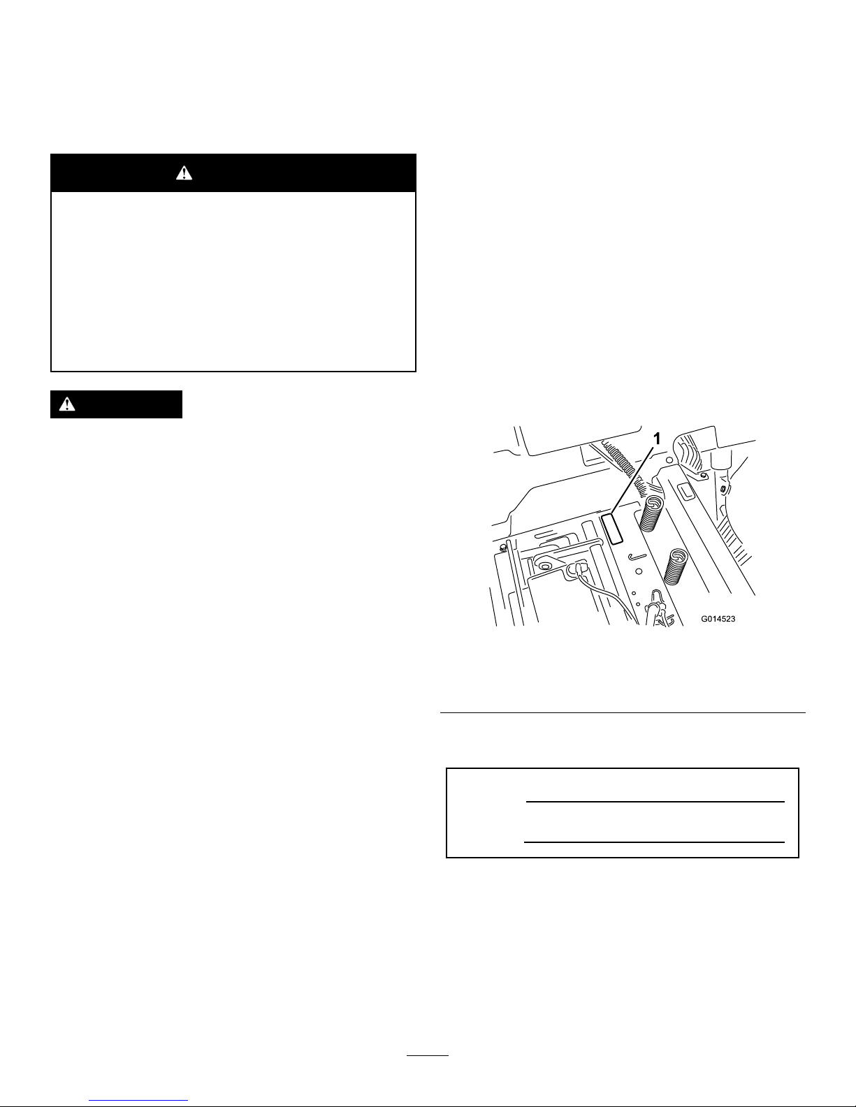
yourproductready.Figure1identiesthelocationofthe
modelandserialnumbersontheproduct.Writethenumbers
inthespaceprovided.
G014523
1
Figure1
Undertheseat
1.Modelandserialnumberplate
Writetheproductmodelandserialnumbersinthespace
below:
ModelNo.
SerialNo.
Thismanualidentiespotentialhazardsandhassafety
messagesidentiedbythesafetyalertsymbol(Figure2),
whichsignalsahazardthatmaycauseseriousinjuryordeath
ifyoudonotfollowtherecommendedprecautions.
©2014—TheToro®Company
8111LyndaleAvenueSouth
Bloomington,MN55420
2
Contactusatwww.Toro.com.
PrintedintheUSA
AllRightsReserved
Page 3

Figure2
1.Safetyalertsymbol.
Thismanualusestwowordstohighlightinformation.
Importantcallsattentiontospecialmechanicalinformation
andNoteemphasizesgeneralinformationworthyofspecial
attention.
Contents
Safety...........................................................................4
SafeOperatingPractices...........................................4
ToroRidingMowerSafety........................................6
SlopeIndicator.......................................................7
SafetyandInstructionalDecals.................................8
ProductOverview.........................................................12
Controls...............................................................12
Operation....................................................................13
ThinkSafetyFirst...................................................13
TestingtheSafety-InterlockSystem...........................15
BeforeStarting.......................................................15
StartingtheEngine.................................................16
OperatingtheBlades...............................................17
StoppingtheEngine...............................................17
Driving.................................................................17
StoppingtheMachine.............................................19
AdjustingtheHeight-of-Cut....................................19
AdjustingtheAnti-ScalpRollers...............................19
PositioningtheSeat................................................20
AdjustingtheMotionControlLevers........................20
PushingtheMachinebyHand..................................20
GrassDeector......................................................21
TransportingtheMachine........................................21
OperatingTips......................................................22
Maintenance.................................................................24
RecommendedMaintenanceSchedule(s)......................24
PremaintenanceProcedures........................................24
RaisingtheSeat......................................................24
Lubrication...............................................................25
GreasingtheBearings.............................................25
EngineMaintenance..................................................25
ServicingtheAirCleaner.........................................25
ServicingtheEngineOil..........................................26
ServicingtheSparkPlug..........................................28
ServicingtheSparkPlug..........................................29
FuelSystemMaintenance...........................................30
ReplacingtheIn-lineFuelFilter................................31
ElectricalSystemMaintenance....................................31
ChargingtheBattery...............................................31
ServicingtheFuses.................................................32
DriveSystemMaintenance.........................................33
CheckingtheTirePressure......................................33
ReleasingtheElectricBrake.....................................34
CoolingSystemMaintenance......................................34
CleaningtheEngineScreen......................................34
CleaningtheEngineCoolingFinsand
Shrouds.............................................................34
MowerMaintenance...................................................35
ServicingtheCuttingBlades.....................................35
LevelingtheMowerDeck........................................37
RemovingtheMower..............................................39
MowerBeltMaintenance.........................................39
InstallingtheMower...............................................40
ReplacingtheGrassDeector..................................40
Cleaning...................................................................41
WashingtheUndersideoftheMower........................41
Storage........................................................................42
CleaningandStorage..............................................42
Troubleshooting...........................................................43
Schematics...................................................................45
3
Page 4

Safety
Toreducethepotentialforinjury,complywiththese
safetyinstructionsandalwayspayattentiontothesafety
alertsymbol,whichmeansCAUTION,WARNING,
orDANGER-"personalsafetyinstruction."Failure
tocomplywiththeinstructionmayresultinpersonal
injuryordeath.
SafeOperatingPractices
Thisproductiscapableofamputatinghandsandfeetand
throwingobjects.Alwaysfollowallsafetyinstructionsto
avoidseriousinjuryordeath.
ThefollowinginstructionsareadaptedfromANSIstandard
B71.1-2012.AllthelanguagewithinthisANSIstandard
appliestothismachine;however,duetotheapplicationof
thestandardacrossmanydifferenttypesofproductssome
statementscanseemgeneralormisleading.Intheseinstances,
Torohasrenedthestatementtoconveythemeaningofthe
standardwhilebettermatchingtheproductthisOperator's
Manualpertains.Safetyinformationinadditiontothe
instructionsfoundintheANSIstandardbelowcanbefound
inToroRidingMowerSafetyattheendofthissection.
GeneralOperation
•Read,understand,andfollowallinstructionsinthe
operator'smanualandonthemachinebeforestarting.
•Donotplacehandsorfeetnearrotatingpartsorunder
themachine.Keepclearofthedischargeopeningatall
times.
•Allowonlyresponsibleadultswhoarefamiliarwiththe
instructionstooperatethemachine.
•Cleartheareaofobjectssuchasrocks,toys,wire,etc.,
whichcouldbepickedupandthrownbytheblade.
•Besuretheareaisclearofotherpeoplebeforemowing.
Stopthemachineifanyoneentersthearea.
•Nevercarrypassengers.
•Donotmowinreverseunlessabsolutelynecessary.
Alwayslookdownandbehindbeforeandwhilebacking
up.
•Beawareofthemowerdischargedirectionanddonot
pointitatanyone.Avoiddischargingmaterialagainsta
wallorobstruction.Materialmayricochetbacktoward
theoperator.Stoptheblade(s)whencrossinggravel
surfaces.
•Donotoperatethemachinewithoutdeector,discharge
coverorentiregrasscollectionsysteminplaceand
working.
•Bealert,slowdownandusecautionwhenmakingturns.
Lookbehindandtothesidebeforechangingdirections.
•Neverleavearunningmachineunattended.Alwaysturn
offblades,setparkingbrake,stopengine,andremovekey
beforedismounting.
•Turnoffbladeswhennotmowing.Stoptheengine,wait
forallpartstocometoacompletestopandremovethe
keybeforecleaningthemachine,removingthegrass
catcheroruncloggingthedischargechute.
•Operatethemachineonlyindaylightorgoodarticial
light.
•Donotoperatethemachinewhileundertheinuence
ofalcoholordrugs.
•Watchfortrafcwhenoperatingnearorcrossing
roadways.
•Useextracarewhenloadingorunloadingthemachine
intoatrailerortruck.
•Alwaysweareyeprotectionwhenoperatingthemower.
•Dataindicatesthatoperators,age60yearsandabove,are
involvedinalargepercentageofridingmower-related
injuries.Operatorsshouldevaluatetheirabilitytooperate
theridingmowersafelyenoughtoprotectthemselvesand
othersfromseriousinjury.
•Alwaysfollowtherecommendationsforanyapplication
ofcounterweights.
•Lightningcancausesevereinjuryordeath.Iflightning
isseenorthunderisheardinthearea,donotoperate
themachine;seekshelter.
SlopeOperation
Slopesareamajorfactorrelatedtolossofcontroland
tip-overaccidents,whichcanresultinsevereinjuryordeath.
Operationonallslopesrequiresextracaution.Ifyoucannot
backuptheslopeorifyoufeeluneasyonit,donotmowit.
•Donotmowslopesgreaterthan15degrees.
•Watchforditches,holes,rocks,dips,andrisesthatchange
theoperatingangle,asroughterraincouldoverturnthe
machine.
•Choosealowgroundspeedsoyouwillnothavetostop
whileoperatingonaslope.
•Donotmowslopeswhengrassiswet.Slippery
conditionsreducetractionandcouldcauseslidingand
lossofcontrol.
•Alwayskeepthedrivewheelsengagedwhengoingdown
slopes.
•Reducespeedanduseextremecautiononslopes.
•Donotmakesuddenturnsorrapidspeedchanges.
•Removeormarkobstaclessuchasrocks,treelimbs,etc.
fromthemowingarea.Tallgrasscanhideobstacles.
•Avoidsuddenstartswhenmowinguphillbecausethe
mowermaytipbackwards.
•Beawarethatlossoftractionmayoccurgoingdownhill.
Weighttransfertothefrontwheelsmaycausedrive
wheelstoslipandcauselossofbrakingandsteering.
4
Page 5

•Alwaysavoidsuddenstartingorstoppingonaslope.If
tireslosetraction,stopthemachine,disengagetheblades
andproceedslowlyofftheslope.
•Useextremecarewithgrasscatchersorotherattachments.
Thesecanchangethestabilityofthemachineandcause
lossofcontrol.
•Donottrytostabilizethemachinebyputtingyourfoot
ontheground.
•Donotmowneardrop-offs,ditches,steepbanksor
water.Wheelsdroppingoveredgescancauserollovers,
whichmayresultinseriousinjury,deathordrowning.
•Useawalkbehindmowerand/orahandtrimmernear
drop-offs,ditches,steepbanksorwater.
Children
Tragicaccidentscanoccuriftheoperatorisnotalerttothe
presenceofchildren.Childrenareoftenattractedtothe
machineandthemowingactivity.Neverassumethatchildren
willremainwhereyoulastsawthem.
•Keepchildrenoutofthemowingareaandunderthe
watchfulcareofanotherresponsibleadult,notthe
operator.
•Bealertandturnthemachineoffifchildrenenterthe
area.
•Beforeandwhilebackingorchangingdirection,look
behind,down,andside-to-sideforsmallchildren.
•Nevercarrychildren,evenwiththebladesoff.Theymay
falloffandbeseriouslyinjuredorinterferewithsafe
machineoperation.
•Childrenwhohavebeengivenridesinthepastmay
suddenlyappearinthemowingareaforanotherrideand
berunoverorbackedoverbythemower.
•Neverallowchildrentooperatethemachine.
•Useextracarewhenapproachingblindcorners,shrubs,
trees,theendofafenceorotherobjectsthatmayobscure
vision.
TowingSafety
•Donotattachtowedequipmentexceptatthehitchpoint.
•Followtheattachmentmanufacturer'srecommendation
forweightlimitsfortowedequipmentandtowingon
slopes.Towedweightmustnotexceedtheweightofthe
machine,operator,andballast.Usecounterweightsor
wheelweightsasdescribedintheattachment,orinthe
pullingmachineOperator’sManual.
•Neverallowchildrenorothersinorontowedequipment.
•Onslopes,theweightofthetowedequipmentmaycause
lossoftraction,increasedriskofrollover,andlossof
control.Reducethetowedweightandslowdown.
•Stoppingdistanceincreaseswiththeweightofthetowed
load.Travelslowlyandallowextradistancetostop.
•Makewideturnstokeeptheattachmentclearofthe
machine.
Service
SafeHandlingofGasoline:
Toavoidpersonalinjuryorpropertydamage,useextracare
whenhandlinggasolineandotherfuels.Theyareammable
andthevaporsareexplosive.
•Extinguishallcigarettes,cigars,pipesandothersources
ofignition.
•Useonlyanapprovedcontainer.
•Neverremovethegascaporaddfuelwhentheengineis
running.Allowtheenginetocoolbeforerefueling.
•Neverrefuelthemachineindoors.
•Neverstorethemachineorfuelcontainerinsidewhere
thereisanopename,suchasnearawaterheateror
furnace.
•Neverllcontainersinsideavehicleoronatruckor
trailerwithaplasticliner.Alwaysplacecontainersonthe
groundawayfromyourvehiclebeforelling.
•Removegas-poweredequipmentfromthetruckortrailer
andrefuelitontheground.Ifthisisnotpossible,then
refuelsuchequipmentwithaportablecontainer,rather
thanfromagasolinedispensernozzle.
•Keepthenozzleincontactwiththerimofthefueltank
orcontaineropeningatalltimesuntilthefuelingis
complete.Donotuseanozzlelock-opendevice.
•Iffuelisspilledonclothing,changeclothingimmediately.
•Neveroverllthefueltank.Replacegascapandtighten
securely.
GeneralService:
•Neveroperateamachineinsideaclosedarea.Engine
exhaustcontainscarbonmonoxide,whichisanodorless,
deadlypoisonthatcankillyou.
•Keepnutsandboltstight,especiallythebladeattachment
bolts.Keepequipmentingoodcondition.
•Neverinterferewiththeintendedfunctionofasafety
deviceorreducetheprotectionprovidedbyasafety
device.Checktheirproperoperationregularly.
•Keepthemachinefreeofgrass,leaves,orotherdebris
build-up.Cleanupoilorfuelspillagefuelsoakeddebris.
Allowthemachinetocoolbeforestoring.
•Stopandinspecttheequipmentifyoustrikeanobject.
Repair,ifnecessary,beforerestarting.
•Nevermakeanyadjustmentsorrepairswiththeengine
running.
•Grasscatchercomponentsaresubjecttowear,damage
anddeterioration,whichcouldexposemovingpartsor
allowobjectstobethrown.Frequentlycheckcomponents
andreplacewithmanufacturers'recommendedparts,
whennecessary.
•Mowerbladesaresharpandcancut.Wraptheblade(s)or
weargloves,anduseextracautionwhenservicingthem.
•Checkforproperbrakeoperationfrequently .Adjustand
serviceasrequired.
5
Page 6

•Maintainorreplacesafetyandinstructiondecalsas
necessary.
•UseonlygenuineTororeplacementpartstoensurethat
originalstandardsaremaintained.
ToroRidingMowerSafety
ThefollowinglistcontainssafetyinformationspecictoToro
productsorothersafetyinformationthatyoumustknowthat
maynotbeincludedintheANSIstandards.
•Stoptheengine,movethemotioncontrolleversto
neutralandoutwardtotheparkposition,disengagethe
bladecontrolswitch,removethekeyanddisconnectthe
sparkplugwire(s)beforeperforminganyservice,repairs,
maintenanceoradjustments.
•Keephands,feet,hair,andlooseclothingawayfrom
attachmentdischargearea,undersideofmowerandany
movingpartswhileengineisrunning.
•Donottouchequipmentorattachmentpartswhichmay
behotfromoperation.Allowtocoolbeforeattempting
tomaintain,adjustorservice.
•Batteryacidispoisonousandcancauseburns.Avoid
contactwithskin,eyes,andclothing.Protectyourface,
eyes,andclothingwhenworkingwithabattery.
•Batterygasescanexplode.Keepcigarettes,sparksand
amesawayfrombattery.
•UseonlyToroapprovedattachments.Warrantymaybe
voidedifusedwithunapprovedattachments.
•Ifloadingthemachineontoatrailerortruck,useasingle,
full-widthramponly.Therampangleshouldnotexceed
15degrees.
6
Page 7
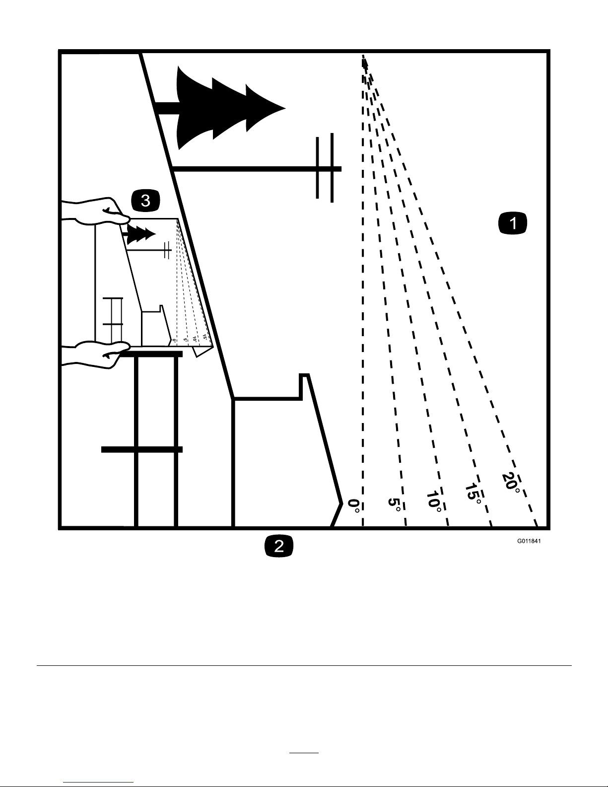
SlopeIndicator
G011841
Figure3
Thispagemaybecopiedforpersonaluse.
1.Themaximumslopeyoucansafelyoperatethemachineonis15degrees.Usetheslopecharttodeterminethedegreeofslope
ofhillsbeforeoperating.Donotoperatethismachineonaslopegreaterthan15degrees.Foldalongtheappropriateline
tomatchtherecommendedslope.
2.Alignthisedgewithaverticalsurface,atree,building,fencepole,etc.
3.Exampleofhowtocompareslopewithfoldededge.
7
Page 8
SafetyandInstructional
Decals
Safetydecalsandinstructionsareeasilyvisibletotheoperatorandarelocatednearanyareaofpotential
danger.Replaceanydecalthatisdamagedorlost.
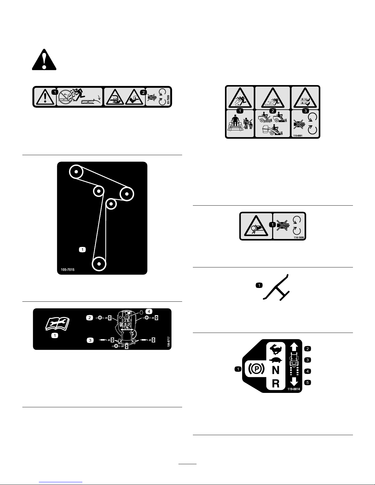
93-7009
1.Warning—don'toperatethemowerwiththedeectorupor
removed;keepthedeectorinplace.
2.Cutting/dismembermenthazardofhandorfoot,mower
blade—stayawayfrommovingparts.
105-7015
ForModelswith42InchDecks
106-8717
1.Readtheinstructionsbeforeservicingorperforming
maintenance.
2.Checktirepressureevery25operatinghours.
3.Greaseevery25operatinghours.
4.Engine
110-6691
1.Thrownobjecthazard—keepbystandersasafedistance
fromthemachine.
2.Thrownobjecthazard,mower—donotoperatewithoutthe
deector,dischargecover,orgrasscollectionsystemin
place.
3.Cutting/dismembermentofhandorfoot—stayawayfrom
movingparts.
114-1606
1.Entanglementhazard,belt—keepallguardsinplace.
Manufacturer'sMark
1.Indicatesthebladeisidentiedasapartfromtheoriginal
machinemanufacturer.
119-8814
1.Parkingposition4.Neutral
2.Fast5.Reverse
3.Slow
8
Page 9

119-8815
1.Parkingposition4.Neutral
2.Fast5.Reverse
3.Slow
119-8871
42InchModel
1.Height-of-cut
121-2989
1.Bypassleverpositionfor
pushingthemachine
2.Bypassleverpositionfor
operatingthemachine
BatterySymbols
Someorallofthesesymbolsareonyourbattery
1.Explosionhazard
6.Keepbystandersasafe
distancefromthebattery.
2.Nore,opename,or
smoking.
7.Weareyeprotection;
explosivegasescan
causeblindnessandother
injuries
3.Causticliquid/chemical
burnhazard
8.Batteryacidcancause
blindnessorsevereburns.
4.Weareyeprotection9.Flusheyesimmediately
withwaterandgetmedical
helpfast.
5.ReadtheOperator's
Manual.
10.Containslead;donot
discard.
9
Page 10

131–3947
1.Trim—slow
3.Mow—fast
2.Tow—medium
131-4036
1.Donottoworpullweights
greaterthan36kg(80lbs).
2.ReadtheOperator's
Manual.
10
Page 11
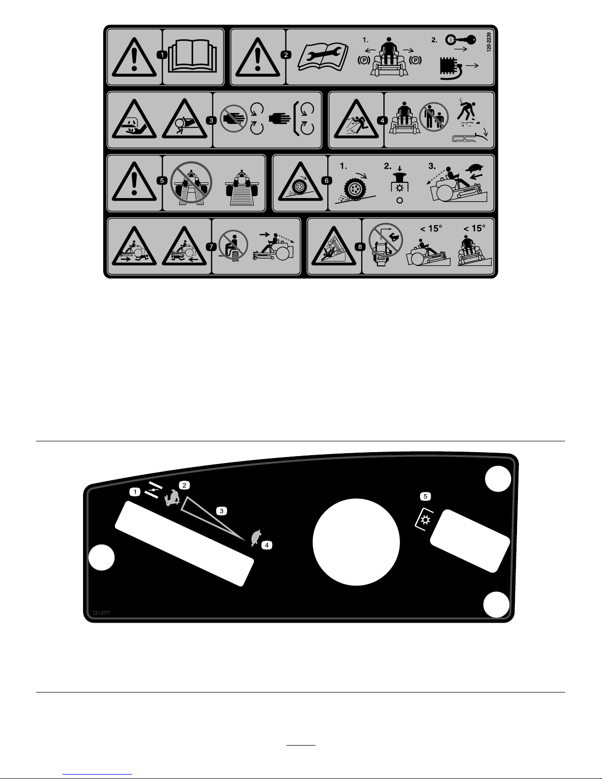
120-2239
1.Warning—readtheOperator'sManual.5.Warning—donotusesplitramps,useafullrampswhen
transportingmachine.
2.Warning—readtheinstructionsbeforeservicingorperforming
maintenance;movethemotioncontrolleverstothepark
(brake)position,removetheignitionkeyanddisconnectthe
sparkplugwire.
6.Lossoftraction/controlhazard,slopes—lossoftraction/control
onaslope,disengagethebladecontrolswitch(PTO),
proceedofftheslopeslowly.
3.Cutting/dismembermenthazard,mowerblade;entanglement
hazard,belt—stayawayfrommovingparts,keepallguards
andshieldsinplace.
7.Crushing/dismembermenthazardofbystanders,reversing;
crushing/dismembermenthazardofbystanders—donotcarry
passengers,lookbehindanddownwhenreversing.
4.Thrownobjecthazard—keepbystandersasafedistancefrom
themachine,pickupdebrisbeforeoperating,keepdeector
inplace.
8.Tippinghazard—donotmowslopesgreaterthan15degrees,
avoidsuddenandsharpturnswhileonslopes.
121-0771
1.Choke4.Slow
2.Fast
5.Powertake-off(PTO),Bladecontrolswitch
3.Continuousvariablesetting
11
Page 12

ProductOverview
Figure4
1.Deector6.Operatorseat
2.Reardrivewheel7.Fueltankcap
3.Controlpanel8.Smartspeedlever
4.Motioncontrollevers9.Footrest
5.Heightofcutlever
10.Frontcasterwheel
Controls
BecomefamiliarwithallofthecontrolsinFigure4and
Figure5beforeyoustarttheengineandoperatethemachine.
Figure5
ControlPanel
1.Throttle/Choke
3.Bladecontrolswitch
(powertake-off)
2.Ignitionswitch
IgnitionSwitch
Theignitionswitchhasthreepositions,Off,RunandStart.
ThekeywillturntoStartandmovebacktoRunuponrelease.
TurningthekeytotheOffpositionwillstoptheengine;
however,alwaysremovethekeywhenleavingthemachine
topreventsomeonefromaccidentallystartingtheengine
(Figure5).
Throttle/ChokeControl
Thethrottleandchokeiscombinedintoonecontrollever.
Thethrottlecontrolstheenginespeedandithasacontinuous
variablesettingfromSlowtoFast.Engagethechokeby
movingtheleverpasttheFastsettinguntilitstops(Figure5).
BladeControlSwitch(PowerTake-Off)
Thebladecontrolswitch,representedbyapowertake-off
(PTO)symbol,engagesanddisengagespowertothemower
blades(Figure5).
MotionControlLeversandPark
Position
Themotioncontrolleversarespeedsensitivecontrolsof
independentwheelmotors.Movingaleverforwardor
backwardturnsthewheelonthesamesideforwardorin
reverse;wheelspeedisproportionaltotheamountthelever
ismoved.Movethecontrolleversoutwardfromthecenter
totheparkpositionandexitthemachine(Figure14).Always
positionthemotioncontrolleversintotheparkposition
whenyoustopthemachineorleaveitunattended.
SmartSpeed™ControlSystemLever
TheSmartSpeed™Control-Systemlever,locatedbelowthe
operatingposition,givestheoperatorachoicetodrivethe
machineat3speedranges—trim,tow ,andmow(Figure6).
Figure6
1.Smart-speedlever
12
Page 13
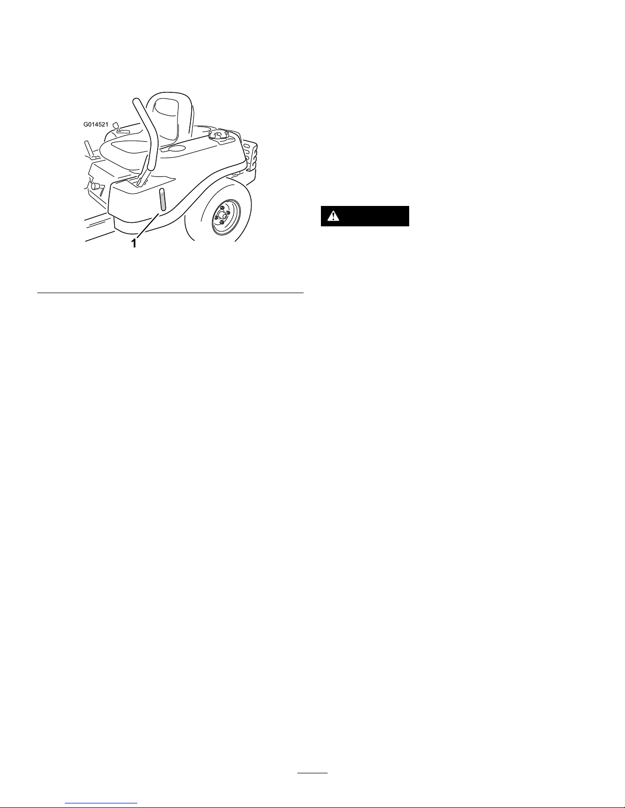
FuelWindow
Thefuelwindowlocatedonthelefthandsideofthemachine
canbeusedtoverifythepresenceofgasolineinthetank
(Figure7).
G014521
1
Figure7
1.Fuelpresencewindow
Height-of-CutLever
Theheightofcutleverallowstheoperatortolowerand
raisethedeckfromtheseatedposition.Whentheleveris
movedup,towardtheoperatorthedeckisraisedfromthe
groundandwhenmoveddown,awayfromtheoperatoritis
loweredtowardtheground.Onlyadjusttheheightofcut
whilemachineisnotmoving(Figure4).
Operation
Note:Determinetheleftandrightsidesofthemachine
fromthenormaloperatingposition.
ThinkSafetyFirst
OperatingSafety
Pleasecarefullyreadallofthesafetyinstructionsanddecals
inthesafetysection.Knowingthisinformationcouldhelp
you,yourfamily ,petsorbystandersavoidinjury.
DANGER
Mowingonwetgrassorsteepslopescancause
slidingandlossofcontrol.
Wheelsdroppingoveredgescancauserollovers,
whichmayresultinseriousinjury,deathor
drowning.
Alossoftractionisalossofsteeringcontrol.
Toavoidlossofcontrolandpossibilityofrollover:
•Donotmowneardrop-offsornearwater.
•Donotmowslopesgreaterthan15degrees.
•Reducespeedanduseextremecautionon
slopes.
•Whenmowingslopes,graduallyworkfrom
lowertohigherareasontheincline.
•Avoidsuddenturnsorrapidspeedchanges.
•Turnup,intoaninclinewhenchanging
directionsonslopes.Turningdowntheslope
reducestraction.
•Attachmentschangethehandlingcharacteristics
ofthemachine.Useextracautionwhenusing
attachmentswiththemachine.
13
Page 14
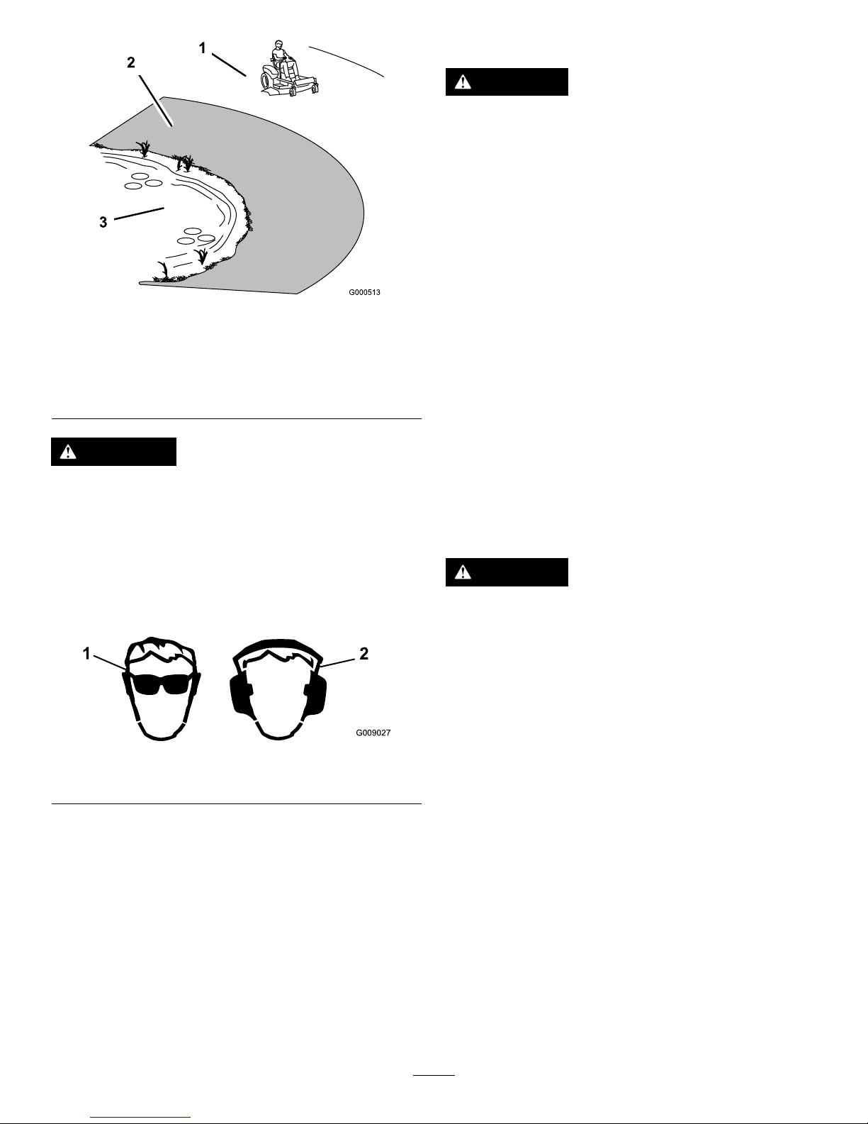
Figure8
1.SafeZone-usethe
TimeCutterhere
3.Water
2.Usewalkbehindmower
and/orhandtrimmernear
drop-offsandwater.
CAUTION
Thismachineproducessoundlevelsinexcessof85
dBAattheoperatorsearandcancausehearingloss
throughextendedperiodsofexposure.
Wearhearingprotectionwhenoperatingthis
machine.
Theuseofprotectiveequipmentforeyes,ears,hands,feet,
andheadisrecommended.
G009027
1
2
Figure9
1.Wearsafetyglasses
2.Wearhearingprotection
FuelSafety
DANGER
Incertainconditions,gasolineisextremely
ammableandhighlyexplosive.Areorexplosion
fromgasolinecanburnyouandothersandcan
damageproperty.
•Fillthefueltankoutdoors,inanopenarea,
whentheengineiscold.Wipeupanygasoline
thatspills.
•Neverllthefueltankinsideanenclosedtrailer.
•Donotllthefueltankcompletelyfull.Add
gasolinetothefueltankuntilthefuelreaches
thebaseofthellerneck.Thisemptyspacein
thetankallowsgasolinetoexpand.
•Neversmokewhenhandlinggasoline,andstay
awayfromanopenameorwheregasoline
fumesmaybeignitedbyaspark.
•Storegasolineinanapprovedcontainerand
keepitoutofthereachofchildren.Neverbuy
morethana30-daysupplyofgasoline.
•Donotoperatewithoutentireexhaustsystemin
placeandinproperworkingcondition.
DANGER
Incertainconditionsduringfueling,static
electricitycanbereleasedcausingasparkwhich
canignitethegasolinevapors.Areorexplosion
fromgasolinecanburnyouandothersandcan
damageproperty.
•Alwaysplacegasolinecontainersontheground
awayfromyourvehiclebeforelling.
•Donotllgasolinecontainersinsideavehicleor
onatruckortrailerbedbecauseinteriorcarpets
orplastictruckbedlinersmayinsulatethe
containerandslowthelossofanystaticcharge.
•Whenpractical,removegas-poweredequipment
fromthetruckortrailerandrefueltheequipment
withitswheelsontheground.
•Ifthisisnotpossible,thenrefuelsuch
equipmentonatruckortrailerfromaportable
container,ratherthanfromagasolinedispenser
nozzle.
•Ifagasolinedispensernozzlemustbeused,
keepthenozzleincontactwiththerimofthe
fueltankorcontaineropeningatalltimesuntil
fuelingiscomplete.
14
Page 15

WARNING
Gasolineisharmfulorfatalifswallowed.Long-term
exposuretovaporscancauseseriousinjuryand
illness.
•Avoidprolongedbreathingofvapors.
•Keepfaceawayfromnozzleandgastankor
conditioneropening.
•Keepgasawayfromeyesandskin.
UnderstandingtheSafetyInterlock
System
WARNING
Ifsafetyinterlockswitchesaredisconnectedor
damagedthemachinecouldoperateunexpectedly
causingpersonalinjury.
•Donottamperwiththeinterlockswitches.
•Checktheoperationoftheinterlockswitches
dailyandreplaceanydamagedswitchesbefore
operatingthemachine.
Thesafetyinterlocksystemisdesignedtopreventtheengine
fromstartingunless:
•Thebladesaredisengaged.
•Themotioncontrolleversareintheparkposition.
Thesafetyinterlocksystemalsoisdesignedtostoptheengine
wheneverthecontrolleversareoutoftheparkpositionand
yourisefromtheseat.
TestingtheSafety-Interlock
System
Testthesafety-interlocksystembeforeyouusethemachine
eachtime.Ifthesafetysystemdoesnotoperateasdescribed
below,haveanAuthorizedServiceDealerrepairthesafety
systemimmediately.
1.Whilesittingontheseat,withthecontrolleversinpark
position,andmovetheblade-controlswitchtoOn.
2.Trystartingtheengine;theengineshouldnotcrank.
3.Whilesittingontheseat,movetheblade-control
switchtoOff.
4.Moveeithermotion-controllevertothecenter,
unlockedposition.
5.Trystartingtheengine;theengineshouldnotcrank.
6.Repeatwiththeothermotion-controllever.
7.Whilesittingontheseat,movetheblade-control
switchtoOff,andlockthemotion-controlleversin
theparkposition.
8.Starttheengine.
9.Whiletheengineisrunning,engagetheblade-control
switch,andriseslightlyfromtheseat.
Note:Theengineshouldstop.
10.Whilesittingontheseat,movetheblade-control
switchtoOff,andlockthemotion-controlleversin
theparkposition.
11.Starttheengine.
12.Whiletheengineisrunning,movethemotion-control
leverstothecenter,unlockedposition,engagethe
blade-controlswitch,andriseslightlyfromtheseat.
Note:Theengineshouldstop.
BeforeStarting
RecommendedFuel
•Forbestresults,useonlyclean,fresh(lessthan30days
old),unleadedgasolinewithanoctaneratingof87or
higher((R+M)/2ratingmethod).
•Ethanol:Gasolinewithupto10%ethanol(gasohol)
or15%MTBE(methyltertiarybutylether)byvolume
isacceptable.EthanolandMTBEarenotthesame.
Gasolinewith15%ethanol(E15)byvolumeisnot
approvedforuse.Neverusegasolinethatcontains
morethan10%ethanolbyvolume,suchasE15
(contains15%ethanol),E20(contains20%ethanol),or
E85(containsupto85%ethanol).Usingunapproved
gasolinemaycauseperformanceproblemsand/orengine
damagewhichmaynotbecoveredunderwarranty.
•Donotusegasolinecontainingmethanol.
•Donotstorefueleitherinthefueltankorfuelcontainers
overthewinterunlessafuelstabilizerisused.
•Donotaddoiltogasoline.
UsingStabilizer/Conditioner
Useafuelstabilizer/conditionerinthemachinetoprovide
thefollowingbenets:
•Keepsgasolinefreshduringstorageof90daysorless.
Forlongerstorageitisrecommendedthatthefueltank
bedrained.
•Cleanstheenginewhileitruns.
•Eliminatesgum-likevarnishbuildupinthefuelsystem,
whichcauseshardstarting.
Addthecorrectamountofgasstabilizer/conditionertothe
gas.
Note:Afuelstabilizer/conditionerismosteffectivewhen
mixedwithfreshgasoline.Tominimizethechanceofvarnish
depositsinthefuelsystem,usefuelstabilizeratalltimes.
15
Page 16

FillingtheFuelTank
Note:Ensurethattheengineisshutoffandthemotion
controlsareintheparkedposition.
Note:Youcanusethefuelwindowtoverifythepresenceof
gasolinebeforellingthetank(Figure10).
Important:Donotoverllfueltank.Fillthefueltank
tothebottomofthellerneck.Theemptyspaceinthe
tankallowsthefueltoexpand.Overllingmayresultin
fuelleakage,damagetotheengine,ordamagetothe
emissionssystem.
g027243
A
B
E
D
C
Figure10
CheckingtheEngineOilLevel
Beforeyoustarttheengineandusethemachine,checktheoil
levelintheenginecrankcase;refertoCheckingtheOilLevel
intheEngineMaintenancesection.
StartingtheEngine
Note:Itmaybenecessarytoholdtheleveragainstthestop,
inthechokeposition,whiletryingtostarttheengine(Figure
11).
Important:Donotengagethestarterformorethan
5secondsatatime.Engagingthestartermotorfor
morethan5secondscandamagethestartermotor.If
theenginefailstostart,wait10secondsbeforeoperating
theenginestarteragain.
g027535
B
C
D
E
A
G
F
Figure11
16
Page 17

OperatingtheBlades
Theblade-controlswitch,representedbyapowertake-off
(PTO)symbol,engagesanddisengagespowertothemower
blades.Thisswitchcontrolspowertoanyattachmentsthat
drawpowerfromtheengine,includingthemowerdeckand
cuttingblades.
EngagingtheBlades
Important:Donotengagethebladeswhenparkedin
tallgrass.Beltorclutchdamagecanoccur.
Note:Alwaysengagethebladeswiththethrottleinthe
Fastposition.
Figure12
DisengagingtheBlades
g027247
Figure13
1.Controlpanel2.Blade-controlswitch—Off
StoppingtheEngine
1.Disengagethebladesbypushingtheblade-control
switchtoOff(Figure13).
2.MovethethrottlelevertotheSlowposition.
Note:Runitatidlespeedforapproximatelyone
minute.
3.TurntheignitionkeytoOffandremovethekey.
Driving
Drivingthemachinebenetsfromanunderstandingof
whatzero-turn-radiusmowermeans.Thedrivewheelsturn
independently,poweredbyhydraulicmotorsoneachaxle;
henceonesidecanturninreversewhiletheotherturns
forwardcausingthemachinetospinratherthanturn.This
vastlyimprovesthemachinemaneuverabilitybutmayrequire
someadjustmentiftheoperatorisunfamiliar.
WARNING
Themachinecanspinveryrapidly.Theoperator
maylosecontrolofthemachineandcausepersonal
injuryordamagetothemachine.
•Usecautionwhenmakingturns.
•Slowthemachinedownbeforemakingsharp
turns.
Thethrottlecontrolregulatestheenginespeedasmeasured
inrpm(revolutionsperminute).Placingthethrottlecontrol
intheFastpositioncanbebestforperformance.Formost
applications,operatinginthefull-throttlepositionisdesirable.
Figure14
1.Park(brake)position
4.Backward
2.Center,unlockposition5.Frontofthemachine
3.Forward
17
Page 18

UsingtheSmartSpeed
TM
Control
System
TheSmartSpeed
TM
Control-Systemlever,locatedbelowthe
operatingposition(Figure15),givestheoperatorachoice
todrivethemachineat3groundspeedranges—trim,tow ,
andmow .
Figure15
1.Smartspeedlever
Tochangespeeds,dothefollowing:
1.Movethemotioncontrolleverstoneutralandoutward
totheparkposition.
2.Disengagethebladecontrolswitch
3.Adjustthelevertothedesiredposition.
Thefollowingareonlyrecommendationsforuse.
Adjustmentswillvarybygrasstype,moisturecontent,and
theheightofthegrass.
Suggested
uses:
TrimTowMow
ParkingX
Heavy,wet
grass
X
TrainingX
BaggingX
MulchingX
Normal
mowing
X
TransportX
Trim
Thisisthelowestspeed.Thesuggestedusesforthisspeed
areasfollows:
•Parking
•Heavy,wetgrassmowingconditions
•Training
Tow
Thisisthemediumspeed.Thesuggestedusesforthisspeed
areasfollows:
•Bagging
•Mulching
Mow
Thisisthefastestspeed.Thesuggestedusesforthisspeed
areasfollows:
•Normalmowing
•Transportingthemachine
DrivingForward
1.Movetheleverstothecenter,unlockedposition.
2.Togoforward,slowlypushthemotion-controllevers
forward(Figure16).
G008952
Figure16
Togostraight,applyequalpressuretoboth
motion-controllevers(Figure16).
Toturn,releasepressureonthemotion-controllever
towardthedirectionyouwanttoturn(Figure16).
Thefartheryoumovethemotion-controlleversin
eitherdirection,thefasterthemachinewillmovein
thatdirection.
Tostop,pullthemotion-controlleverstoneutral.
18
Page 19

DrivingBackward
Note:Alwaysusecautionwhenbackingupandturning.
1.Movetheleverstothecenter,unlockedposition.
2.Togobackward,lookbehindyouanddown,asyou
slowlypullthemotion-controlleversrearward(Figure
17).
G008953
Figure17
Togostraight,applyequalpressuretoboth
motion-controllevers(Figure17).
Toturn,releasethepressureonthemotion-control
levertowardthedirectionyouwanttoturn.
Tostop,pushthemotion-controlleverstoneutral.
StoppingtheMachine
Tostopthemachine,movethemotioncontrolleversto
neutralandoutwardtotheparkposition,disengagetheblade
controlswitch,movethethrottlelevertotheSlowposition,
runitatidlespeedforapproximatelyoneminute,.andturn
theignitionkeytooff.Remembertoremovethekeyfrom
theignitionswitch.
WARNING
Childrenorbystandersmaybeinjuredifthey
moveorattempttooperatethemowerwhileitis
unattended.
Alwaysremovetheignitionkeyandmovethe
motioncontrolleversoutwardtotheparkposition
whenleavingthemachineunattended,evenifjust
forafewminutes.
AdjustingtheHeight-of-Cut
Note:Thetransportpositionisthehighestheight-of-cut
positionorcuttingheight(115mm(4.5inches))asshown
inFigure18.
Figure18
AdjustingtheAnti-Scalp
Rollers
Wheneveryouchangetheheight-of-cut,itisrecommended
toadjusttheheightoftheanti-scalprollers.
Note:Adjusttheanti-scalprollerssotherollersdonottouch
thegroundinnormal,atmowingareas.
1.Disengagethebladecontrolswitch(PTO),movethe
motioncontrolleverstotheneutrallockpositionand
settheparkingbrake.
2.Stoptheengine,removethekey,andwaitforallmoving
partstostopbeforeleavingtheoperatingposition.
3.Adjusttheanti-scalprollerstooneofthefollowing
positions:
19
Page 20

•Upperhole—usethispositionwiththemowerdeck
inthe63mm(2-1/2inch)andbelowheight-of-cut
positions(Figure19).
•Lowerhole—usethispositionwiththemower
deckinthe76mm(3inch)andaboveheight-of-cut
positions(Figure19).
g019929
1
2
3
4
5
Figure19
1.Anti-scalproller4.Upperhole—themower
deckinthe63mm
(2-1/2inch)andbelow
height-of-cutpositions
2.Lowerhole—themower
deckinthe76mm(3inch)
andaboveheight-of-cut
positions
5.Bolt
3.FlangeNut
PositioningtheSeat
Theseatcanmoveforwardandbackward.Positiontheseat
whereyouhavethebestcontrolofthemachineandaremost
comfortable(Figure20).
g027249
B
C
A
Figure20
AdjustingtheMotionControl
Levers
AdjustingtheHeight
Themotioncontrolleverscanbeadjustedhigherorlowerfor
maximumoperatorcomfort(Figure21).
g027252
B
A
Figure21
AdjustingtheTilt
Themotioncontrolleverscanbetiltedforeoraftfor
maximumoperatorcomfort.
1.Loosentheupperboltholdingthecontrollevertothe
controlarmshaft.
2.Loosenthelowerboltjustenoughtopivotthecontrol
leverforeoraft(Figure21).Tightenbothboltsto
securethecontrolinthenewposition.
3.Repeattheadjustmentfortheoppositecontrollever.
PushingtheMachinebyHand
Important:Alwayspushthemachinebyhand.Never
towthemachinebecausedamagemayoccur.
Thismachinehasanelectricbrakemechanismandtopush
themachinetheignitionkeyneedstobeintheRunposition.
Thebatteryneedstobechargedandfunctioningforthe
electricbraketobedisengage.
ToPushtheMachine
1.Parkthemachineonalevelsurfaceanddisengagethe
bladecontrolswitch.
2.Movethemotioncontrolleversoutwardtopark
position,stoptheengine,andwaitforallmovingparts
tostopbeforeleavingtheoperatingposition.
3.Locatethebypassleversontheframeonbothsidesof
theengine.
4.Movethebypassleversforwardthroughthekeyhole
anddowntolocktheminplaceasshowninFigure22.
Ensurethisisdoneforeachlever.
20
Page 21

5.Movethemotioncontrolleversinwardtotheneutral
positionandturntheignitionkeytotherunposition.
Donotstartthemachine.
Themachineisnowabletobepushedbyhand.
g017303
1 2
3
Figure22
1.Bypassleverlocations
3.Leverpositionforpushing
themachine
2.Leverpositionfor
operatingthemachine
6.Whennished,ensurethekeyhasbeenreturnedtothe
Stoppositiontoavoiddrainingthebatterycharge.
Ifthemachinefailstomovetheelectricbrakemaystillbe
engaged.Ifnecessarytheelectricbrakecanbereleased
manually.RefertoReleasingtheElectricBrake(page34).
ToOperatetheMachine
Movethebypassleversrearwardthroughthekeyholeand
downtolocktheminplaceasshown(Figure22).Ensurethis
isdoneforeachlever.
GrassDeector
Themowerhasahingedgrassdeectorthatdisperses
clippingstothesideanddowntowardtheturf.
DANGER
Withoutthegrassdeector,dischargecover,or
completegrasscatcherassemblymountedin
place,youandothersareexposedtobladecontact
andthrowndebris.Contactwithrotatingmower
blade(s)andthrowndebriswillcauseinjuryor
death.
•Neverremovethegrassdeectorfromthemower
becausethegrassdeectorroutesmaterialdown
towardtheturf.Ifthegrassdeectorisever
damaged,replaceitimmediately .
•Neverputyourhandsorfeetunderthemower.
•Nevertrytocleardischargeareaormower
bladesunlessyoumovethebladecontrolswitch
toOffandrotatetheignitionkeytoOff.Also
removethekeyandpullthewireoffthespark
plug(s).
TransportingtheMachine
Useaheavy-dutytrailerortrucktotransportthemachine.
Ensurethatthetrailerortruckhasallnecessarybrakes,
lighting,andmarkingasrequiredbylaw .Pleasecarefullyread
allthesafetyinstructions.Knowingthisinformationcould
helpyou,yourfamily,pets,orbystandersavoidinjury.
WARNING
Drivingonthestreetorroadwaywithoutturn
signals,lights,reectivemarkings,oraslow
movingvehicleemblemisdangerousandcanlead
toaccidentscausingpersonalinjury.
Donotdrivemachineonapublicstreetorroadway.
Totransportthemachine:
1.Ifusingatrailer,connectittothetowingvehicleand
connectthesafetychains.
2.Ifapplicable,connectthetrailerbrakes.
3.Loadthemachineontothetrailerortruck.
4.Stoptheengine,removethekey,setthebrake,and
closethefuelvalve.
5.Tiedownthemachinenearthefrontcasterwheelsand
therearbumper(Figure23).
21
Page 22

Figure23
OperatingTips
FastThrottleSetting
Forbestmowingandmaximumaircirculation,operatethe
engineattheFastposition.Airisrequiredtothoroughlycut
grassclippings,sodonotsettheheight-of-cutsolowasto
totallysurroundthemowerbyuncutgrass.Alwaystrytohave
onesideofthemowerfreefromuncutgrass,whichallowsair
tobedrawnintothemower.
UsingtheSmartSpeed™Control
System
TheSmartSpeed™ControlSystemlever,locatedbelow
theoperatingposition,givestheoperatorachoicetodrive
themachineatthreespeedranges—high,tow,andlow .An
operatorcanbenetfromthelowerspeedsettingwhen
maneuveringthemachineintightspacesoroperatingaround
delicatelandscapes.Thelowsettingcanalsobeusedto
operatethemachineatahighthrottlesettingandbladespeed
whilestillbeingabletoreducegroundspeedtoincrease
qualityofcut.
CuttingaLawnfortheFirstTime
Cutgrassslightlylongerthannormaltoensurethatthe
cuttingheightofthemowerdoesnotscalpanyuneven
ground.However,thecuttingheightusedinthepastis
generallythebestonetouse.Whencuttinggrasslongerthan
sixinchestall,youmaywanttocutthelawntwicetoensure
anacceptablequalityofcut.
Cut1/3oftheGrassBlade
Itisbesttocutonlyabout1/3ofthegrassblade.Cutting
morethanthatisnotrecommendedunlessgrassissparse,or
itislatefallwhengrassgrowsmoreslowly.
MowingDirection
Alternatemowingdirectiontokeepthegrassstanding
straight.Thisalsohelpsdisperseclippingswhichenhances
decompositionandfertilization.
MowatCorrectIntervals
Normally,moweveryfourdays.Butremember,grassgrows
atdifferentratesatdifferenttimes.Sotomaintainthesame
cuttingheight,whichisagoodpractice,mowmoreoftenin
earlyspring.Asthegrassgrowthrateslowsinmidsummer,
mowlessfrequently.Ifyoucannotmowforanextended
period,rstmowatahighcuttingheight;thenmowagain
twodayslateratalowerheightsetting.
AvoidCuttingTooLow
Ifthecuttingwidthofthemoweriswiderthanthemower
youpreviouslyused,raisethecuttingheighttoensurethat
uneventurfisnotcuttooshort.
22
Page 23

LongGrass
Ifthegrassiseverallowedtogrowslightlylongerthan
normal,orifitcontainsahighdegreeofmoisture,raisethe
cuttingheighthigherthanusualandcutthegrassatthis
setting.Thencutthegrassagainusingthelower,normal
setting.
WhenStopping
Ifthemachine'sforwardmotionmustbestoppedwhile
mowing,aclumpofgrassclippingsmaydropontoyour
lawn.Toavoidthis,moveontoapreviouslycutareawiththe
bladesengagedoryoucandisengagethemowerdeckwhile
movingforward.
KeeptheUndersideoftheMowerClean
Cleanclippingsanddirtfromtheundersideofthemower
aftereachuse.Ifgrassanddirtbuildupinsidethemower,
cuttingqualitywilleventuallybecomeunsatisfactory.
BladeMaintenance
Maintainasharpbladethroughoutthecuttingseasonbecause
asharpbladecutscleanlywithouttearingorshreddingthe
grassblades.Tearingandshreddingturnsgrassbrownat
theedges,whichslowsgrowthandincreasesthechanceof
disease.Checkthecutterbladesdailyforsharpness,andfor
anywearordamage.Filedownanynicksandsharpenthe
bladesasnecessary.Ifabladeisdamagedorworn,replaceit
immediatelywithagenuineT ororeplacementblade.
23
Page 24

Maintenance
Note:Determinetheleftandrightsidesofthemachinefromthenormaloperatingposition.
RecommendedMaintenanceSchedule(s)
MaintenanceService
Interval
MaintenanceProcedure
Aftertherst5hours
•Changetheengineoil.
Beforeeachuseordaily
•Checkthesafety-interlocksystem.
•Cleanandchecktheaircleanerfoamelement.
•Checktheengineoillevel.
•Cleantheengineairintakescreen.
•Checkthecuttingblades.
•Inspectthegrassdeectorfordamage
Aftereachuse
•Cleanthemowerhousing.
Every25hours
•Greasealllubricationpoints.
•Checktirepressure.
•Checkthebeltsforwear/cracks.
Every50hours
•Replacetheaircleanerpaperelement.
•Checkthesparkplug.
•Checkthesparkplug.
Every100hours
•Changetheengineoil(changeitmoreoftenunderaheavyloadorinhigh
temperatures).
•Changetheengine-oillter.
•Replacethesparkplug.
•Replacethesparkplug.
•Replacethein-linefuellter.
•Cleantheenginecoolingnsandshrouds.
Beforestorage
•Chargethebatteryanddisconnectbatterycables.
•Performallmaintenanceprocedureslistedabovebeforestorage.
•Paintanychippedsurfaces.
Important:Refertoyourengineoperator'smanualforadditionalmaintenanceprocedures.
CAUTION
Ifyouleavethekeyintheignitionswitch,someonecouldaccidentlystarttheengineandseriouslyinjure
youorotherbystanders.
Removethekeyfromtheignitionanddisconnectthewirefromthesparkplugbeforeyoudoany
maintenance.Setthewireasidesothatitdoesnotaccidentallycontactthesparkplug.
Premaintenance
Procedures
RaisingtheSeat
Makesurethemotioncontrolleversarelockedinthepark
position.Lifttheseatforward.
Thefollowingcomponentscanbeaccessedbyraisingtheseat:
•Serialplate
•Servicedecal
•Seatadjustmentbolts
•Fuellter
•Batteryandbatterycables
24
Page 25

Lubrication
GreasingtheBearings
ServiceInterval:Every25hours—Greasealllubrication
points.
GreaseType:No.2GeneralPurposeLithiumBaseGrease
1.Parkthemachineonalevelsurfaceanddisengagethe
bladecontrolswitch.
2.Movethemotioncontrolleversoutwardtothepark
position,stoptheengine,removethekey ,andwaitfor
allmovingpartstostopbeforeleavingtheoperating
position.
3.Cleanthegreasettings(Figure24andFigure25)with
arag.Makesuretoscrapeanypaintoffofthefront
ofthetting(s).
1
G014522
Figure24
1.Frontcastertire
Figure25
Locatedontheseatpanunderside
1.Readtheinstructions
beforeservicingor
performingmaintenance.
3.Greaseevery25operating
hours.
2.Checktirepressureevery
25operatinghours.
4.Engine
4.Connectagreaseguntoeachtting(Figure24and
Figure25).Pumpgreaseintothettingsuntilgrease
beginstooozeoutofthebearings.
5.Wipeupanyexcessgrease.
EngineMaintenance
ServicingtheAirCleaner
ServiceInterval:Beforeeachuseordaily—Cleanandcheck
theaircleanerfoamelement.
Every50hours—Replacetheaircleanerpaper
element.
Note:Servicetheaircleanermorefrequentlyiftheoperating
conditionsareextremelydustyorsandy.
RemovingtheFoamandPaper
Elements
1.Disengagethebladecontrol(PTO).
2.Stoptheengine,waitforallmovingpartstostop,and
removethekeybeforeleavingtheoperatingposition.
3.Cleanaroundtheaircleanertopreventdirtfrom
gettingintotheengineandcausingdamage.
4.Removetheaircleanercoverbyunscrewingthe2
knobs(Figure26).
G017862
Figure26
1.Aircleanercover2.Knobs
5.Carefullyremovethefoamandpaperlterelements
fromtheaircleanerhousing(Figure27).
25
Page 26

Figure27
1.Foamelement2.Paperelement
6.Separatethefoamandpaperelements.
CleaningtheFoamandPaperElements
FoamElement:
1.Washthefoamelementinliquidsoapandwarmwater.
Whentheelementisclean,rinseitthoroughly .
2.Drytheelementbysqueezingitinacleancloth.Do
notoiltheelement.
Important:Replacethefoamelementifitistorn
orworn.
3.Installthefoamelementonacleanpaperelement.
PaperElement:
1.Tapthepaperelementonasolidatsurfaceandblow
itoutfromtheinsidewithcompressedairtoremove
dustanddirt.
2.Inspecttheelementfortears,anoilylm,anddamage
totherubberseal.
Important:Donotcleanthepaperelementwith
liquids,suchassolvents,gasoline,orkerosene.
Replacethepaperelementifitisdamagedor
cannotbecleanedthoroughly.
3.Cleantheinsideoftheaircleanercoverofalldirt,dust,
anddebris.
InstallingtheFoamandPaperElements
Important:Topreventenginedamage,alwaysoperate
theenginewiththecompletefoamandpaperaircleaner
assemblyinstalled.
1.Installthefoamlterontothepaperlter(Figure27).
2.Installthefoamandpaperlterontotheaircleaner
housing.
3.Installtheaircleanercoverandtightenthetwoknobs
(Figure26).
ServicingtheEngineOil
OilType:Detergentoil(APIserviceSF ,SG,SH,SJ,or
higher)
CrankcaseCapacity:1.0L(34oz)whenyoudonotchange
thelter;1.05L(36oz)whenyouchangethelter.
Viscosity:Seethetablebelow.
Figure28
CheckingtheEngine-OilLevel
ServiceInterval:Beforeeachuseordaily
Note:Checktheoilwhentheengineiscold.
WARNING
Contactwithhotsurfacesmaycausepersonal
injury.
Keephands,feet,face,clothingandotherbody
partsawaythemuferandotherhotsurfaces.
Important:Donotoverllthecrankcasewithoiland
runtheengine;enginedamagemayresult.
1.Parkthemachineonalevelsurface.
2.Disengagetheblade-controlswitch(PTO).
3.Stoptheengine,waitforallmovingpartstostop,and
removethekeybeforeleavingtheoperatingposition.
4.Checktheengine-oillevel(Figure29).
26
Page 27

B
A
C
D
E
G027475
F
G
H
I J
Figure29
ChangingtheEngineOil
ServiceInterval:Aftertherst5hours
Every100hours(changeitmoreoftenunderaheavy
loadorinhightemperatures).
1.Parkthemachine,sothattherightsideisslightly
lowerthantheleftside,toensurethattheoildrains
completely.
2.Disengagetheblade-controlswitch(PTO).
3.Stoptheengine,waitforallmovingpartstostop,and
removethekeybeforeleavingtheoperatingposition.
B
A
C D
E F
g027476
Figure30
4.Slowlypourapproximately80%ofthespecied
amountofoilintothellhole(Figure31).
27
Page 28

B
A
C
D
E
F
g027484
Figure31
5.Checktheoillevel;refertoCheckingtheEngine-Oil
Level(page26).
ChangingtheEngine-OilFilter
ServiceInterval:Every100hours
Note:Changetheengine-oilltermorefrequentlywhenthe
operatingconditionsareextremelydustyorsandy.
1.Draintheoilfromtheengine;refertoChangingthe
EngineOil(page27).
B
A
C D
E
F
3/4
g027477
Figure32
Note:Ensuretheoil-ltergaskettouchestheengine,
andthenanextra3/4turniscompleted.
2.Fillthecrankcasewiththepropertypeofnewoil;refer
toChangingtheEngineOil(page27).
ServicingtheSparkPlug
ServiceInterval:Every50hours—Checkthesparkplug.
Every100hours—Replacethesparkplug.
Ensurethattheairgapbetweenthecenterandsideelectrodes
iscorrectbeforeinstallingthesparkplug.Useasparkplug
wrenchforremovingandinstallingthesparkpluganda
gappingtoolorfeelergaugetocheckandadjusttheairgap.
Installanewsparkplugifnecessary.
Type:ChampionRC12YC,Autolite3924,NGKBCPR6ES
orequivalent
AirGap:0.76mm(0.030inch)
RemovingtheSparkPlug
1.Disengagethebladecontrol(PTO).
2.Stoptheengine,waitforallmovingpartstostop,and
removethekeybeforeleavingtheoperatingposition.
3.Disconnectthewirefromthesparkplug(Figure33).
28
Page 29

B
A
g027478
Figure33
1.Spark-plugwire
4.Cleanaroundthesparkplugtopreventdirtfromfalling
intotheengineandpotentiallycausingdamage.
5.Removethesparkplugandmetalwasher.
CheckingtheSparkPlug
1.Inspectthesparkplug(Figure34).
Note:Ifyouseelightbrownorgrayontheinsulator,
theengineisoperatingproperly .Ablackcoatingonthe
insulatorusuallymeansthattheaircleanerisdirty.
B
A
g027479
Figure34
1.Centerelectrodeinsulator3.Airgap(nottoscale)
2.Sideelectrode
Important:Donotcleanthesparkplug.Always
replacethesparkplugwhenithasablackcoating,
wornelectrodes,anoilylm,orcracks.
2.Checkthegapbetweenthecenterandsideelectrodes
(Figure34).Bendthesideelectrodeifthegapisnot
correct.
InstallingtheSparkPlug
Tightenthesparkplugto20N-m(15ft-lb).
B
A
15 ft-lb
20 N-m
g027480
C
D
Figure35
ServicingtheSparkPlug
ServiceInterval:Every50hours—Checkthesparkplug.
Every100hours—Replacethesparkplug.
Ensurethattheairgapbetweenthecenterandsideelectrodes
iscorrectbeforeinstallingthesparkplug.Useasparkplug
wrenchforremovingandinstallingthesparkpluganda
gappingtoolorfeelergaugetocheckandadjusttheairgap.
Installanewsparkplugifnecessary.
Type:ChampionRC12YC,Autolite3924,NGKBCPR6ES
orequivalent
AirGap:0.76mm(0.03inch)
RemovingtheSparkPlug
1.Disengagetheblade-controlswitch,movethemotion
controlsoutwardtotheparkposition,stoptheengine,
andremovethekey.
2.Beforeremovingthesparkplug(s),cleanthearea
aroundthebaseoftheplugtokeepdirtanddebrisout
oftheengine.
3.Removethesparkplug(Figure36).
29
Page 30

B
A
g027478
Figure36
CheckingtheSparkPlug
Important:Donotcleanthesparkplug(s).Always
replacethesparkplug(s)whenithas:ablackcoating,
wornelectrodes,anoilylm,orcracks.
Note:Ifyouseelightbrownorgrayontheinsulator,the
engineisoperatingproperly.Ablackcoatingontheinsulator
usuallymeanstheaircleanerisdirty.
Setthegapto0.76mm(0.030inch).
B
A
g027479
Figure37
InstallingtheSparkPlug
Tightenthesparkplugto20N-m(15ft-lb).
B
A
15 ft-lb
20 N-m
g027480
C
D
Figure38
FuelSystem
Maintenance
DANGER
Incertainconditions,gasolineisextremely
ammableandhighlyexplosive.Areorexplosion
fromgasolinecanburnyouandothersandcan
damageproperty.
•Performanyfuelrelatedmaintenancewhenthe
engineiscold.Dothisoutdoorsinanopenarea.
Wipeupanygasolinethatspills.
•Neversmokewhendraininggasoline,andstay
awayfromanopenameorwhereasparkmay
ignitethegasolinefumes.
30
Page 31

ReplacingtheIn-lineFuel
Filter
ServiceInterval:Every100hours—Replacethein-linefuel
lter.
Neverinstalladirtylterifitisremovedfromthefuelline.
1.Parkthemachineonalevelsurfaceanddisengagethe
blade-controlswitch.
2.Settheparkingbrake,stoptheengine,removethekey,
andwaitforallmovingpartstostopbeforeleavingthe
operatingposition.
g027506
B
A
C
D
g027753
Figure39
ElectricalSystem
Maintenance
WARNING
CALIFORNIA
Proposition65Warning
Batteryposts,terminals,andrelated
accessoriescontainleadandleadcompounds,
chemicalsknowntotheStateofCalifornia
tocausecancerandreproductiveharm.
Washhandsafterhandling.
ChargingtheBattery
RemovingtheBattery
WARNING
Batteryterminalsormetaltoolscouldshortagainst
metalmachinecomponentscausingsparks.Sparks
cancausethebatterygassestoexplode,resulting
inpersonalinjury.
•Whenremovingorinstallingthebattery,donot
allowthebatteryterminalstotouchanymetal
partsofthemachine.
•Donotallowmetaltoolstoshortbetween
thebatteryterminalsandmetalpartsofthe
machine.
1.Parkthemachineonalevelsurfaceanddisengagethe
bladecontrolswitch.
2.Movethemotioncontrolleversoutwardtothepark
position,stoptheengine,removethekey ,andwaitfor
allmovingpartstostopbeforeleavingtheoperating
position.
3.Raisetheseattoaccessthebattery.
4.Disconnectthenegative(black)groundcablefromthe
batterypost(Figure40).Retainallfasteners.
WARNING
Incorrectbatterycableroutingcoulddamage
themachineandcablescausingsparks.
Sparkscancausethebatterygassesto
explode,resultinginpersonalinjury.
•Alwaysdisconnectthenegative(black)
batterycablebeforedisconnectingthe
positive(red)cable.
•Alwaysconnectthepositive(red)battery
cablebeforeconnectingthenegative
(black)cable.
31
Page 32

5.Slidetherubbercoverupthepositive(red)cable.
Disconnectthepositive(red)cablefromthebattery
post(Figure40).Retainallfasteners.
6.Removethebatteryhold-down(Figure40)andliftthe
batteryfromthebatterytray .
G005072
1
2
3
4
5
6
7
Figure40
1.Battery5.Negativebatterypost
2.Positivebatterypost6.Wingnut,washer,andbolt
3.Bolt,washer,andnut7.Batteryhold-down
4.T erminalboot
ChargingtheBattery
ServiceInterval:Beforestorage—Chargethebatteryand
disconnectbatterycables.
1.Removethebatteryfromthechassis;refertoRemoving
theBattery.
2.Chargethebatteryforaminimumof1hourat6to10
amps.Donotoverchargethebattery.
3.Whenthebatteryisfullycharged,unplugthecharger
fromtheelectricaloutlet,thendisconnectthecharger
leadsfromthebatteryposts(Figure41).
Figure41
1.Positivebatterypost
3.Red(+)chargerlead
2.Negativebatterypost
4.Black(-)chargerlead
InstallingtheBattery
1.Positionthebatteryinthetray(Figure40).
2.Installthepositive(red)batterycabletothepositive(+)
batteryterminalusingthefastenersremovedpreviously.
3.Installthenegativebatterycabletothenegative(-)
batteryterminalusingthefastenersremovedpreviously.
4.Slidetheredterminalbootontothepositive(red)
batterypost.
5.Securethebatterywiththehold-down(Figure40).
6.Lowertheseat.
ServicingtheFuses
Theelectricalsystemisprotectedbyfuses.Itrequires
nomaintenance;however,ifafuseblows,checkthe
component/circuitforamalfunctionorshort.
Fuse:
•MainF1-30amp,blade-type
•ChargeCircuitF2-25amp,blade-type
1.Removethescrewssecuringthecontrolpaneltothe
machine.Retainallfasteners
2.Liftthecontrolpaneuptoaccessthemainwiring
harnessandfuseblock(Figure42).
3.Toreplaceafuse,pulloutonthefusetoremoveit
(Figure42).
32
Page 33

30
25
30
25
G014540
2
1
Figure42
1.Main-30amp
2.Chargecircuit-25amp
4.Returnthecontrolpaneltoitsoriginalposition.Use
thescrewsremovedpreviouslytosecurethepanelto
themachine.
DriveSystem
Maintenance
CheckingtheTirePressure
ServiceInterval:Every25hours—Checktirepressure.
Maintaintheairpressureinthefrontandreartiresas
specied.Uneventirepressurecancauseunevencut.Check
thepressureatthevalvestem(Figure43).Checkthetires
whentheyarecoldtogetthemostaccuratepressurereading.
Refertothemaximumpressuresuggestedbythetire
manufactureronthesidewallofthecasterwheeltires.
Inatethereardrivewheeltiresto90kPa(13psi).
Figure43
1.V alvestem
33
Page 34

ReleasingtheElectricBrake
Theelectricbrakereleasesbymanuallyrotatingthelinkarms
forward.Oncetheelectricbrakeisenergizedthebrakewill
reset.
Toreleasethebrake:
1.TurntheignitionkeytotheOffpositionordisconnect
thebattery.
2.Locatetheshaftswherethebrake-linkarmsare
connectedonbothsidesoftheelectricbrake(Figure
44).
3.Rotatetheshaftsforwardtoreleasethebrakes.
Figure44
1.Rotatebrake-linkarmforwardontheelectric-brake-control
module
2.Leftreartire
CoolingSystem
Maintenance
CleaningtheEngineScreen
ServiceInterval:Beforeeachuseordaily—Cleantheengine
airintakescreen.
Toensurepropercooling,makesurethegrassscreen,cooling
ns,andotherexternalsurfacesoftheenginearekeptclean
atalltimes.
Useadrybrushtocleangrassandaccumulateddebrisfrom
theairintakescreenandaroundtheengine.
Important:Topreventcontaminatingthefuelsystem,
donotusewatertocleantheengine.
CleaningtheEngineCooling
FinsandShrouds
ServiceInterval:Every100hours—Cleantheenginecooling
nsandshrouds.
1.Disengagethebladecontrolswitchandmovethe
controlleverstotheneutrallockedpositionandapply
theparkingbrake.
2.Stoptheengine,removethekey,andwaitforallmoving
partstostopbeforeleavingtheoperatingposition.
3.Removetheairintakescreenandcoolingshrouds.
4.Cleanthedebrisandgrassfromtheengineparts.
5.Installtheairintakescreenandcoolingshrouds.
34
Page 35

MowerMaintenance
ServicingtheCuttingBlades
Maintainsharpbladesthroughoutthecuttingseason,because
sharpbladescutcleanlywithouttearingorshreddingthegrass
blades.Tearingandshreddingturnsgrassbrownattheedges,
whichslowsgrowth,andincreasesthechanceofdisease.
Checkthecutterbladesdailyforsharpness,andforany
wearordamage.Filedownanynicksandsharpenthe
bladesasnecessary.Ifabladeisdamagedorworn,replace
itimmediatelywithagenuineT ororeplacementblade.For
convenientsharpeningandreplacement,youmaywantto
keepextrabladesonhand.
WARNING
Awornordamagedbladecanbreak,andapiece
ofthebladecouldbethrownintotheoperator's
orbystander'sarea,resultinginseriouspersonal
injuryordeath.
•Inspectthebladeperiodicallyforwearor
damage.
•Replaceawornordamagedblade.
BeforeInspectingorServicingthe
Blades
Parkthemachineonalevelsurface,disengagethe
blade-controlswitch,movethemotion-controlleversoutward
totheparkposition,stoptheengine,andremovethekey .
InspectingtheBlades
ServiceInterval:Beforeeachuseordaily—Checkthe
cuttingblades.
1.Inspectthecuttingedges(Figure45).
Note:Iftheedgesarenotsharporhavenicks,remove
andsharpentheblades;refertoSharpeningtheBlades
(page37).
2.Inspecttheblades,especiallythecurvedarea(Figure
45).
Note:Ifyounoticeanydamage,wear,oraslot
forminginthisarea(items3and4inFigure45),
immediatelyinstallanewblade.
Figure45
1.Cuttingedge3.Wear/slotforming
2.Curvedarea
4.Damage
CheckingforBentBlades
Note:Themachinemustbeonalevelsurfaceforthe
followingprocedure.
1.Raisethemowerdecktothehighestheight-of-cut
position;alsoconsideredthe'transport'position.
2.Whilewearingthicklypaddedgloves,orotheradequate
handprotection,slowlyrotatethebladetobemeasure
intoapositionthatallowseffectivemeasurementofthe
distancebetweenthecuttingedgeandthelevelsurface
themachineison(Figure46).
G009679
1
2
3
Figure46
1.Deck3.Blade
2.Spindlehousing
35
Page 36

3.Measurefromthetipofthebladetotheatsurface
(Figure47).
G009680
1
2
3
Figure47
1.Blade(inpositionformeasuring)
2.Levelsurface
3.Measureddistancebetweenbladeandthesurface(A)
4.Rotatethesameblade180degrees,sothattheopposing
cuttingedgeisnowinthesameposition(Figure48).
G009681
1
2
3
Figure48
1.Blade(sidepreviouslymeasured)
2.Measurement(positionusedpreviously)
3.Opposingsideofbladebeingmovedintomeasurement
position
5.Measurefromthetipofthebladetotheatsurface
(Figure49).
Note:Thevarianceshouldbenomorethan3mm
(1/8inch).
G009680
1
2
3
Figure49
1.Oppositebladeedge(inpositionformeasuring)
2.Levelsurface
3.Secondmeasureddistancebetweenbladeandsurface(B)
A.IfthedifferencebetweenAandBisgreaterthan
3mm(1/8inch),replacethebladewithanew
blade;refertoRemovingtheBlades(page36)and
InstallingtheBlades(page37).
Note:Ifabentbladeisreplacedwithanewone,
andthedimensionobtainedcontinuestoexceed
3mm(1/8inch),thebladespindlecouldbebent.
ContactanAuthorizedToroDealerforservice.
B.Ifthevarianceiswithinconstraints,movetothe
nextblade.
Repeatthisprocedureoneachblade.
RemovingtheBlades
Thebladesmustbereplacedifasolidobjectishit,ifthe
bladeisoutofbalance,orifthebladeisbent.T oensure
optimumperformanceandcontinuedsafetyconformance
ofthemachine,usegenuineTororeplacementblades.
Replacementbladesmadebyothermanufacturersmayresult
innon-conformancewithsafetystandards.
1.Holdthebladeendusingaragorthickly-paddedglove.
2.Removethebladebolt,thecurvedwasher,andthe
bladefromthespindleshaft(Figure50).
36
Page 37

G027833
Figure50
1.Sailareaoftheblade3.Curvedwasher
2.Blade4.Bladebolt
SharpeningtheBlades
1.Usealetosharpenthecuttingedgeatbothendsof
theblade(Figure51).
Note:Maintaintheoriginalangle.
Note:Thebladeretainsitsbalanceifthesameamount
ofmaterialisremovedfrombothcuttingedges.
Figure51
1.Sharpenatoriginalangle
2.Checkthebalanceofthebladebyputtingitonablade
balancer(Figure52).
Note:Ifthebladestaysinahorizontalposition,the
bladeisbalanced,andcanbeused.
Note:Ifthebladeisnotbalanced,lesomemetaloff
theendofthesailareaonly(Figure51).
Figure52
1.Blade2.Balancer
3.Repeatthisprocedureuntilthebladeisbalanced.
InstallingtheBlades
1.Installthebladeontothespindleshaft(Figure50).
Important:Thecurvedpartoftheblademustbe
pointingupwardtowardtheinsideofthemowerto
ensurepropercutting.
2.Installthethecurvedwasher(cuppedsidetowardthe
blade)andthebladebolt(Figure50).
3.Torquethebladeboltto47to88N-m(35to65ft-lb).
LevelingtheMowerDeck
Checktoensurethatthemowerdeckislevelanytimeyou
installthemowerorwhenyouseeanunevencutonyour
lawn.
Themowerdeckmustbecheckedforbentbladespriorto
leveling;anybentbladesmustberemovedandreplaced;
refertotheServicingtheCuttingBlades(page35)before
continuing.
Themowerdeckmustbeleveledside-to-siderstthenthe
fronttorearslopecanbeadjusted.
Requirements:
•Themachinemustbeonalevelsurface.
•Alltiresmustbeproperlyinated;refertoCheckingthe
TirePressure(page33).
LevelingfromSidetoSide
1.Parkthemachineonalevelsurfaceanddisengagethe
blade-controlswitch.
2.Movethemotion-controlleversoutwardtothepark
position,stoptheengine,removethekey ,andwaitfor
allmovingpartstostopbeforeleavingtheoperating
position.
3.Settheheight-of-cutlevertomiddleposition.
4.Carefullyrotatetheblade(s)sothattheyareallside
toside(Figure53).
G009682
1
2
2
3
3
4
4
Figure53
Mowerdeckswith2Blades
1.Bladessidetoside
3.Outsidecuttingedges
2.Sailareaofblade4.Measurefromthetipofthe
bladetotheatsurface
here
37
Page 38

5.Measurebetweentheoutsidecuttingedgesandthe
atsurface(Figure53).Ifbothmeasurementsarenot
within5mm(3/16inch),anadjustmentisrequired;
continuewiththisprocedure.
6.Movetotheleftsideofthemachine.
7.Loosenthesidelockingnut.
8.Raiseorlowertheleftsideofthemowerdeckby
rotatingtherearnut.(Figure54).
Note:Rotatetherearnutclockwisetoraisethemower
deck;rotatetherearnutcounter-clockwisetolower
themowerdeck.
Figure54
1.Hangerbracket3.Rearlockingnut
2.Sidelockingnut
9.Checktheside-to-sideadjustmentsagain.Repeatthis
procedureuntilthemeasurementsarecorrect.
10.Continuelevelingthedeckbycheckingthefront-to-rear
bladeslope;refertoAdjustingtheFront-to-RearBlade
Slope(page38).
AdjustingtheFront-to-RearBlade
Slope
Checkthefront-to-rearbladelevelanytimeyouinstallthe
mower.Ifthefrontofthemowerismorethan7.9mm
(5/16inch)lowerthantherearofthemower,adjusttheblade
levelusingthefollowinginstructions:
1.Parkthemachineonalevelsurfaceanddisengagethe
blade-controlswitch.
2.Movethemotion-controlleversoutwardtothepark
position,stoptheengine,removethekey ,andwaitfor
allmovingpartstostopbeforeleavingtheoperating
position.
3.Settheheight-of-cutlevertomiddleposition.
Note:Checkandadjusttheside-to-sidebladelevel
ifyouhavenotcheckedthesetting;refertoLeveling
fromSidetoSide(page37).
4.Carefullyrotatethebladessotheyarefacingfrontto
rear(Figure55).
G009658
1
2
2
Figure55
Mowerdeckswith2Blades
1.Bladesfronttorear
2.Measurefromthetipofthebladetotheatsurfacehere
5.Measurefromthetipofthefrontbladetotheat
surface,andthetipoftherearbladetotheatsurface
(Figure55).
Note:Ifthefrontbladetipisnot1.6to7.9mm(1/16
to5/16inch)lowerthantherearbladetip,adjustthe
frontlocknut.
6.Toadjustthefront-to-rearbladeslope,rotatethe
adjustmentnutinthefrontofthemower(Figure56).
G014634
1
2
3
Figure56
1.Adjustingrod3.Locknut
2.Adjustingblock
7.Toraisethefrontofthemower,tightentheadjustment
nut.
8.Tolowerthefrontofthemower,loosentheadjustment
nut.
38
Page 39

9.Afteradjustment,checkthefront-to-rearslopeagain,
continueadjustingthenutuntilthefrontbladetipis
1.6to7.9mm(1/16to5/16inch)lowerthantherear
bladetip(Figure55).
10.Whenthefront-to-rearbladeslopeiscorrectcheckthe
side-to-sidelevelofthemoweragain,refertoLeveling
fromSidetoSide(page37).
RemovingtheMower
1.Parkthemachineonalevelsurfaceanddisengagethe
bladecontrolswitch.
2.Movethemotioncontrolleversoutwardtothepark
position,stoptheengine,removethekey ,andwaitfor
allmovingpartstostopbeforeleavingtheoperating
position.
3.Lowertheheight-of-cutlevertothelowestposition.
4.Removethehairpincotterfromthefrontsupportrod
andremovetherodfromthedeckbracket(Figure
57).Carefullylowerthefrontofthemowerdeckto
theground.
G014635
1
2
3
Figure57
1.Frontsupportrod3.Deckbracket
2.Lockingnut
5.Liftthemowerdeckandhangerbracketsclearof
therearliftrodandlowerthemowercarefullytothe
ground(Figure58).
2
2
3
G005077
1
2
2
3
Figure58
1.Mowerdeck
3.Rearliftrod
2.Hangerbracket
6.Slidethemowerdeckrearwardtoremovethemower
beltfromtheenginepulley.
7.Slidethemowerdeckoutfromunderneaththe
machine.
Note:Retainallpartsforfutureinstallation.
MowerBeltMaintenance
InspectingtheBelts
ServiceInterval:Every25hours—Checkthebeltsfor
wear/cracks.
Checkthebeltsforcracks,frayededges,burnmarks,orany
otherdamage.Replacedamagedbelts.
ReplacingtheMowerBelt
Squealingwhenthebeltisrotating,bladesslippingwhen
cuttinggrass,frayedbeltedges,burnmarks,andcracksare
signsofawornmowerbelt.Replacethemowerbeltifanyof
theseconditionsareevident.
1.Parkthemachineonalevelsurfaceanddisengagethe
bladecontrolswitch.
2.Movethemotioncontrolleversoutwardtothepark
position,stoptheengine,removethekey ,andwaitfor
allmovingpartstostopbeforeleavingtheoperating
position.
3.Settheheight-of-cutatthelowestcuttingposition
[1-1/2inch(38mm)].
4.Usingaspringremovaltool,(Toropartno.92-5771),
removetheidlerspringfromthedeckhooktoremove
tensionontheidlerpulleyandrollthebeltoffofthe
pulleys(Figure59).
39
Page 40

WARNING
Thespringisundertensionwheninstalled
andcancausepersonalinjury.
Becarefulwhenremovingthebelt.
G005078
1
2
3
3
4
5
1
2
3
3
4
5
Figure59
1.Idlerpulley
4.Spring
2.Mowerbelt5.Enginepulley
3.Outsidepulley6.Springremovaltoo
5.Routethenewbeltaroundtheenginepulleyand
mowerpulleys(Figure59).
6.Usingaspringremovaltool,(Toropartno.92-5771),
installtheidlerspringoverthedeckhookandplacing
tensionontheidlerpulleyandmowerbelt(Figure59).
InstallingtheMower
1.Parkthemachineonalevelsurfaceanddisengagethe
bladecontrolswitch.
2.Movethemotioncontrolleversoutwardtothepark
position,stoptheengine,removethekey ,andwaitfor
allmovingpartstostopbeforeleavingtheoperating
position.
3.Slidethemowerunderthemachine.
4.Lowertheheight-of-cutlevertothelowestposition.
5.Lifttherearofthemowerdeckandguidethehanger
bracketsovertherearliftrod(Figure58).
6.Attachthefrontsupportrodtothemowerdeckwith
theclevispinandhairpincotter(Figure57).
7.Installthemowerbeltontotheenginepulley;referto
ReplacingtheMowerBelt.
ReplacingtheGrassDeector
ServiceInterval:Beforeeachuseordaily—Inspectthegrass
deectorfordamage
WARNING
Anuncovereddischargeopeningcouldallowthe
lawnmowertothrowobjectsintheoperator'sor
bystander'sdirectionandresultinseriousinjury.
Also,contactwiththebladecouldoccur.
Neveroperatethemachinewithoutgrassdeector,
dischargecoverorgrasscollectionsysteminplace.
Inspectthegrassdeectorfordamagebeforeeachuse.
Replaceanydamagedpartsbeforeuse.
1.LocateitemsshowninFigure60.
G005303
1
2
3
4
5
6
7
Figure60
1.Mowerdeck
5.Spring
2.Grassdeector6.Nut(3/8inch)
3.Grassdeectorbracket7.Shortstand-off
4.Rod
2.Removethenut(3/8inch)fromtherodunderthe
mower(Figure60).
3.Slidetherodoutoftheshortstand-off,spring,and
grassdeector(Figure60).Removethedamagedor
worngrassdeector.
4.Replacethegrassdeector(Figure60).
5.Sliderod,straightend,throughthereargrassdeector
bracket.
6.Placethespringontherod,withendwiresdown,and
betweenthegrassdeectorbrackets.Sliderodthrough
secondgrassdeectorbracket(Figure60).
7.Insertrodatfrontofgrassdeectorintoshort
stand-offondeck.Securerearendofrodintothe
mowerwithanut(3/8inch)(Figure60).
Important:Thegrassdeectormustbespring
loadedinthedownposition.Liftthedeectorup
totestthatitsnapstothefulldownposition.
40
Page 41

Cleaning
WashingtheUndersideofthe
Mower
ServiceInterval:Aftereachuse—Cleanthemowerhousing.
Important:Y oucanwashthemachinewithamild
detergentandwater.Donotpressurewashthemachine.
Avoidexcessiveuseofwater,especiallynearthecontrol
panel,undertheseat,aroundtheengine,hydraulic
pumps,andmotors.
Washtheundersideofthemoweraftereachusetoprevent
grassbuildupforimprovedmulchactionandclipping
dispersal.
1.Parkthemachineonalevelsurfaceanddisengagethe
bladecontrolswitch.
2.Movethemotioncontrolleversoutwardtothepark
position,stoptheengine,removethekey ,andwaitfor
allmovingpartstostopbeforeleavingtheoperating
position.
3.Attachthehosecouplingtotheendofthemower
washouttting,andturnthewateronhigh(Figure61).
Note:Spreadpetroleumjellyonthewashouttting
O-ringtomakethecouplingslideoneasierandprotect
theO-ring.
G020098
2
4
1
2
3
4
Figure61
1.Washouttting3.O-ring
2.Hose
4.Coupling
4.Lowerthemowertothelowestheight-of-cut.
5.Sitontheseatandstarttheengine.Engagetheblade
controlswitchandletthemowerrunforonetothree
minutes.
6.Disengagethebladecontrolswitch,stoptheengine,
andremovetheignitionkey.Waitforallmovingparts
tostop.
7.Turnthewateroffandremovethecouplingfromthe
washouttting.
Note:Ifthemowerisnotcleanafteronewashing,let
itsoakfor30minutes.Thenrepeattheprocedureof
washingtheundersideofthemower.
8.Runthemoweragainforonetothreeminutesto
removeexcesswater.
WARNING
Abrokenormissingwashoutttingcould
exposeyouandotherstothrownobjectsor
bladecontact.Contactwithbladeorthrown
debriscancauseinjuryordeath.
•Replacebrokenormissingwashouttting
immediately,beforeusingmoweragain.
•Neverputyourhandsorfeetunderthe
mowerorthroughopeningsinthemower.
41
Page 42

Storage
CleaningandStorage
1.Disengagethebladecontrolswitch,movethemotion
controlsoutwardtotheparkposition,stoptheengine,
andremovethekey.
2.Removegrassclippings,dirt,andgrimefromthe
externalpartsoftheentiremachine,especiallythe
engine.Cleandirtandchafffromtheoutsideofthe
enginecylinderheadnsandblowerhousing.
Important:Y oucanwashthemachinewithamild
detergentandwater.Donotpressurewashthe
machine.Avoidexcessiveuseofwater,especially
nearthecontrolpanel,undertheseat,aroundthe
engine,hydraulicpumps,andmotors.
3.Servicetheaircleaner;refertoServicingtheAir
CleanerintheEngineMaintenancesection.
4.Greaseandoilthemachine;refertotheLubrication
section.
5.Changethecrankcaseoilandlter;refertoServicing
theEngineOilintheEngineMaintenancesection.
6.Checkthetirepressure;refertoCheckingtheTire
PressureintheDriveSystemMaintenancesection.
7.Chargethebattery;refertoServicingtheBatteryinthe
ElectricalSystemMaintenancesection.
8.Checktheconditionoftheblades;refertoServicing
theCuttingBladesintheMowerMaintenancesection.
9.Preparethemachineforstoragewhennon-useoccurs
over30days.Preparethemachineforstorageas
follows.
10.Addapetroleumbasedstabilizer/conditionertothe
fuelinthetank.Followthemixinginstructionsfrom
thestabilizermanufacturer.Donotuseanalcohol
basedstabilizer(ethanolormethanol).
Note:Afuelstabilizer/conditionerismosteffective
whenmixedwithfreshgasolineandusedatalltimes.
Runtheenginetodistributetheconditionedfuel
throughthefuelsystem(5minutes).
Stoptheengine,allowittocool,anddrainthefueltank.
Restarttheengineandrunituntilitstops.
Choketheengine.Startandruntheengineuntilitwill
notstart.
Disposeoffuelproperly.Recyclepursuanttolocal
codes.
Important:Donotstorestabilizer/conditioned
gasolineover90days.
11.Removethesparkplug(s)andcheckitscondition;refer
toServicingtheSparkPlugintheEngineMaintenance
section.Withthesparkplug(s)removedfromthe
engine,pourtwotablespoonsofengineoilintothe
sparkplughole.Usethestartertocranktheengineand
distributetheoilinsidethecylinder.Installthespark
plug(s).Donotinstallthewireonthesparkplug(s).
12.Cleananydirtandchafffromthetopofthemower.
13.Scrapeanyheavybuildupofgrassanddirtfromthe
undersideofthemower,thenwashthemowerwith
agardenhose.
14.Checktheconditionofthedriveandmowerbelts.
15.Checkandtightenallbolts,nuts,andscrews.Repairor
replaceanypartthatiswornordamaged.
16.Paintallscratchedorbaremetalsurfaces.Paintis
availablefromyourAuthorizedServiceDealer.
17.Storethemachineinaclean,drygarageorstoragearea.
Removethekeyfromtheignitionswitchandkeepit
inamemorableplace.Coverthemachinetoprotect
itandkeepitclean.
42
Page 43

Troubleshooting
Problem
PossibleCauseCorrectiveAction
1.Theengineloadisexcessive.1.Reducegroundspeed.
2.Theoillevelinthecrankcaseislow.2.Addoiltothecrankcase.
3.Thecoolingnsandairpassages
undertheengineblowerhousingare
plugged.
3.Removetheobstructionfromthe
coolingnsandairpassages.
4.Theaircleanerisdirty.
4.Cleanorreplacetheaircleaner
element.
Theengineoverheats.
5.Dirt,water,orstalefuelisinfuel
system.
5.ContactanAuthorizedServiceDealer
1.Thebladecontrolswitchisengaged.1.Movethebladecontrolswitchto
Disengaged.
2.Themotioncontrolleversarenotinthe
parkposition.
2.Movethemotioncontrolleversoutward
totheparkposition.
3.Thebatteryisdead.
3.Chargethebattery.
4.Theelectricalconnectionsare
corrodedorloose.
4.Checktheelectricalconnectionsfor
goodcontact.
5.Afuseisblown.5.Replacethefuse.
Thestarterdoesnotcrank
6.Arelayorswitchisdamaged.
6.ContactanAuthorizedServiceDealer.
1.Thefueltankisempty.1.Fillthefueltank.
2.Thechokeisnoton.
2.MovethechokelevertoOn.
3.Theaircleanerisdirty.
3.Cleanorreplacetheaircleaner
element.
4.Thesparkplugwire(s)islooseor
disconnected.
4.Installthewire(s)onthesparkplug.
5.Thesparkplug(s)ispitted,fouled,or
thegapisincorrect.
5.Installanew,correctlygappedspark
plug(s).
6.Thereisdirtinfuellter.6.Replacethefuellter.
7.Dirt,water,orstalefuelisinfuel
system.
7.ContactanAuthorizedServiceDealer.
8.Thereisincorrectfuelinthefueltank.8.Drainthetankandreplacethefuelwith
thepropertype.
Theenginewillnotstart,startshard,or
failstokeeprunning.
9.Theoillevelinthecrankcaseislow.9.Addoiltothecrankcase.
1.Theengineloadisexcessive.1.Reducegroundspeed.
2.Theaircleanerisdirty.
2.Cleantheaircleanerelement.
3.Theoillevelinthecrankcaseislow.3.Addoiltothecrankcase.
4.Thecoolingnsandairpassages
undertheengineblowerhousingare
plugged.
4.Removetheobstructionfromthe
coolingnsandairpassages.
5.Thesparkplug(s)ispitted,fouled,or
thegapisincorrect.
5.Installanew,correctlygappedspark
plug(s).
6.Thefueltankventisblocked.6.ContactanAuthorizedServiceDealer.
7.Thereisdirtinthefuellter.7.Replacethefuellter .
8.Dirt,water,orstalefuelisinthefuel
system.
8.ContactanAuthorizedServiceDealer.
Theenginelosespower.
9.Thereisincorrectfuelinthefueltank.9.Drainthetankandreplacethefuelwith
thepropertype.
1.Thebypassvalvesareopen.
1.Closethetowvalves.
2.Thetractionbeltsareworn,loose,or
broken.
2.ContactanAuthorizedServiceDealer.
3.Thetractionbeltsareoffofthepulleys.3.ContactanAuthorizedServiceDealer.
Themachinedoesnotdrive.
4.Thetransmissionhasfailed.4.ContactanAuthorizedServiceDealer.
43
Page 44

Problem
PossibleCauseCorrectiveAction
1.Theenginemountingboltsareloose.1.Tightentheenginemountingbolts.
2.Theenginepulley ,idlerpulley,orblade
pulleyisloose.
2.Tightentheappropriatepulley.
3.Theenginepulleyisdamaged.
3.ContactanAuthorizedServiceDealer.
4.Thecuttingblade(s)is/arebentor
unbalanced.
4.Installanewcuttingblade(s).
5.Ablademountingboltisloose.5.Tightentheblademountingbolt.
Thereisabnormalvibration.
6.Abladespindleisbent.
6.ContactanAuthorizedServiceDealer.
1.Theblade(s)isnotsharp.1.Sharpentheblade(s).
2.Acuttingblade(s)is/arebent.2.Installanewcuttingblade(s).
3.Themowerisnotlevel.
3.Levelthemowerfromside-to-sideand
front-to-rear.
4.Ananti-scalpwheelisnotsetcorrectly .4.Adjusttheanti-scalpwheelheight.
5.Theundersideofthemowerisdirty.5.Cleantheundersideofthemower.
6.Thetirepressureisincorrect.6.Adjustthetirepressure.
Unevencuttingheight.
7.Abladespindleisbent.
7.ContactanAuthorizedServiceDealer.
1.Thedrivebeltisworn,looseorbroken.1.Installanewdrivebelt.
2.Thedrivebeltisoffofthepulley.
2.Installthedrivebeltandcheckthe
adjustingshaftsandbeltguidesforthe
correctposition.
3.ThePowerTake-Off(PTO)switchor
PTOclutchisfaulty.
3.ContactanAuthorizedServiceDealer.
Thebladesdonotrotate.
4.Themowerbeltisworn,loose,or
broken.
4.Installanewmowerbelt.
44
Page 45

Schematics
ElectricalDiagram(Rev .A)
45
Page 46

Notes:
46
Page 47

Notes:
47
Page 48

TheToroTotalCoverageWarranty
Landscape
ALimitedWarranty(seewarrantyperiodsbelow)Contractor
Equipment
(LCE)
ConditionsandProductsCovered
TheToroCompanyanditsafliate,T oroWarrantyCompany,pursuanttoanagreement
betweenthem,jointlypromisetotheoriginalpurchasertorepairtheT oroProducts
listedbelowifdefectiveinmaterialsorworkmanship.
Thefollowingtimeperiodsapplyfromthedateofpurchasebytheoriginalowner:
ProductsWarrantyPeriod
21in.Mowers2yearsResidentialUse
1
1yearCommercialUse
•Engines
4
Honda–2years
Kawasaki–3years
30in.Mowers2yearsResidentialUse
1
1yearCommercialUse
•Engines
4
Kawasaki–3years
Mid-SizeWalk-BehindMowers
2years
•Engines
4
Kawasaki–3years
GrandStand
®
Mowers
5yearsor1,200hours
2
•Engines
4
3years
•Frame
Lifetime(originalowneronly)
3
ZMaster
®
2000SeriesMowers
4yearsor500hours
2
•Engines
4
3years
•Frame
Lifetime(originalowneronly)
3
ZMaster
®
3000SeriesMowers
5yearsor1,200hours
2
•Engines
4
3years
•Frame
Lifetime(originalowneronly)
3
ZMaster
®
5000SeriesMowers
5yearsor1,200hours
2
•Engines
4
KohlerCommand–2years
KohlerEFI–3years
•Frame
Lifetime(originalowneronly)
3
ZMaster
®
6000SeriesMowers
5yearsor1,200hours
2
•Engines
4
Kawasaki–3years
•Frame
Lifetime(originalowneronly)
3
ZMaster
®
7000SeriesMowers
5yearsor1,200hours
2
•Engines
4
2years
•Frame
Lifetime(originalowneronly)
3
ZMaster
®
8000SeriesMowers
2yearsor1,200hours
2
•Engines
4
2years
•Frame
Lifetime(originalowneronly)
3
AllMowers
•Battery90daysPartsandLabor
1yearPartsonly
•BeltsandTires90days
•Attachments1year
1
Residentialusemeansuseoftheproductonthesamelotasyourhome.Useatmorethanone
locationisconsideredcommercialuseandthecommercialwarrantywouldapply.
2
Whicheveroccursrst.
3
LifetimeFrameW arranty-Ifthemainframe,consistingofthepartsweldedtogethertoformthe
tractorstructurethatothercomponentssuchastheenginearesecuredto,cracksorbreaksin
normaluse,itwillberepairedorreplaced,atToro'soption,underwarrantyatnocostforpartsand
labor.Framefailureduetomisuseorabuseandfailureorrepairrequiredduetorustorcorrosion
arenotcovered.
4
SomeenginesusedonToroProductsarewarrantedbytheenginemanufacturer .
InstructionsforObtainingWarrantyService
IfyouthinkthatyourT oroProductcontainsadefectinmaterialsorworkmanship,
followthisprocedure:
1.ContactanyAuthorizedT oroServiceDealertoarrangeserviceattheir
dealership.T olocateadealerconvenienttoyou,refertotheYellowPagesof
yourtelephonedirectory(lookunder“LawnMowers”)oraccessourwebsite
atwww.Toro.com.Y oumayalsocallthenumberslistedinitem#3tousethe
24-hourT oroDealerlocatorsystem.
2.Bringtheproductandyourproofofpurchase(salesreceipt)totheService
Dealer.Thedealerwilldiagnosetheproblemanddetermineifitiscovered
underwarranty.
3.IfforanyreasonyouaredissatisedwiththeServiceDealer’sanalysisorwith
theassistanceprovided,contactusat:
RLCCustomerCareDepartment
ToroWarrantyCompany
811 1LyndaleAvenueSouth
Bloomington,MN55420-1 196
888-865-5676(U.S.Customers)
888-865-5691(Canadacustomers)
OwnerResponsibilities
YoumustmaintainyourT oroProductbyfollowingthemaintenanceprocedures
describedintheOperator'sManual.Suchroutinemaintenance,whetherperformedby
adealerorbyyou,isatyourexpense.
ItemsandConditionsNotCovered
Thereisnootherexpresswarrantyexceptforspecialemissionsystemcoverage
andenginewarrantycoverageonsomeproducts.Thisexpresswarrantydoesnot
coverthefollowing:
•Costofregularmaintenanceserviceorparts,suchaslters,fuel,lubricants,oil
changes,sparkplugs,airltersbladesharpeningorwornblades,cable/linkage
adjustments,orbrakeandclutchadjustments
•Componentsfailingduetonormalwear
•Anyproductorpartwhichhasbeenalteredormisusedorneglectedandrequires
replacementorrepairduetoaccidentsorlackofpropermaintenance
•Pickupanddeliverycharges
•RepairsorattemptedrepairsbyanyoneotherthananAuthorizedT oroService
Dealer
•Repairsnecessaryduetofailuretofollowrecommendedfuelprocedure(consult
Operator'sManualformoredetails)
–Removingcontaminantsfromthefuelsystemisnotcovered
–Useofoldfuel(morethanonemonthold)orfuelwhichcontainsmorethan
10%ethanolormorethat15%MTBE
–Failuretodrainthefuelsystempriortoanyperiodofnon-useoverone
month
GeneralConditions
AllrepairscoveredbythesewarrantiesmustbeperformedbyanAuthorizedT oro
ServiceDealerusingT oroapprovedreplacementparts.
NeitherTheToroCompanynorToroWarrantyCompanyisliableforindirect,
incidentalorconsequentialdamagesinconnectionwiththeuseoftheT oro
Productscoveredbythiswarranty ,includinganycostorexpenseofproviding
substituteequipmentorserviceduringreasonableperiodsofmalfunctionor
non-usependingcompletionofrepairsunderthiswarranty.
Allimpliedwarrantiesofmerchantability(thattheproductistforordinaryuse)
andtnessforuse(thattheproductistforaparticularpurpose)arelimitedto
thedurationoftheexpresswarranty.
Somestatesdonotallowexclusionsofincidentalorconsequentialdamages,
orlimitationsonhowlonganimpliedwarrantylasts,sotheaboveexclusions
andlimitationsmaynotapplytoyou.
Thiswarrantygivesyouspeciclegalrights,andyoumayalsohaveotherrights
whichvaryfromstatetostate.
CountriesOtherthantheUnitedStatesorCanada
CustomerswhohavepurchasedT oroproductsoutsidetheUnitedStatesorCanadashouldcontacttheirT oroDistributor(Dealer)toobtainguaranteepoliciesforyourcountry ,
province,orstate.IfforanyreasonyouaredissatisedwithyourDistributor'sserviceorhavedifcultyobtainingguaranteeinformation,contacttheToroimporter.Ifallother
remediesfail,youmaycontactusatT oroWarrantyCompany .
AustralianConsumerLaw:AustraliancustomerswillnddetailsrelatingtotheAustralianConsumerLaweitherinsidetheboxoratyourlocalT oroDealer.
374-0252RevG
 Loading...