

Page 1
FormNo.3381-516RevA
TimeCutter
®
SS3216Riding
Mower
ModelNo.74629—SerialNo.314000001andUp
Registeratwww.T oro.com.
OriginalInstructions(EN)
*3381-516*A
Page 2
Thismachineisaride-on,rotary-bladelawnmowerintended
tobeusedbyhomeownersinresidentialapplications.Itis
primarilydesignedforcuttinggrassonwell-maintainedlawns.
Itisnotdesignedforcuttingbrush,mowinggrassandother
growthalongsidehighways,orforagriculturaluses.
Important:Thisengineisnotequippedwithaspark
arrestermufer.ItisaviolationofCaliforniaPublic
ResourceCodeSection4442touseoroperatetheengine
onanyforest-covered,brush-covered,orgrass-covered
land.Otherstatesorfederalareasmayhavesimilarlaws.
ThissparkignitionsystemcomplieswithCanadianICES-002.
WARNING
CALIFORNIA
Proposition65Warning
Thisproductcontainsachemicalorchemicals
knowntotheStateofCaliforniatocausecancer,
birthdefects,orotherreproductiveharm.
Theengineexhaustfromthisproduct
containschemicalsknowntotheStateof
Californiatocausecancer,birthdefects,
orotherreproductiveharm.
WARNING
Removingstandardoriginalequipmentpartsand
accessoriesmayalterthewarranty,traction,and
safetyofthemachine.FailuretouseoriginalToro
partscouldcauseseriousinjuryordeath.Making
unauthorizedchangestotheengine,fuelorventing
system,mayviolateEPAandCARBregulations.
Replaceallpartsincluding,butnotlimitedto,tires,
belts,blades,andfuelsystemcomponentswith
originalT oroparts.
GrossHorsepower
Thegrossornethorsepowerofthisenginewaslaboratory
ratedbytheenginemanufacturerinaccordancewiththe
SocietyofAutomotiveEngineers(SAE)J1940.Ascongured
tomeetsafety ,emission,andoperatingrequirements,
theactualenginetorqueonthisclassofmowerwillbe
signicantlylower.
Gotowww.Toro.comtoviewspecicationsonyourmower
model.
Introduction
Readthisinformationcarefullytolearnhowtooperateand
maintainyourproductproperlyandtoavoidinjuryand
productdamage.Youareresponsibleforoperatingthe
productproperlyandsafely .
YoumaycontactTorodirectlyatwww .Toro.comforproduct
andaccessoryinformation,helpndingadealer,ortoregister
yourproduct.
Wheneveryouneedservice,genuineToroparts,oradditional
information,contactanAuthorizedServiceDealerorToro
CustomerServiceandhavethemodelandserialnumbersof
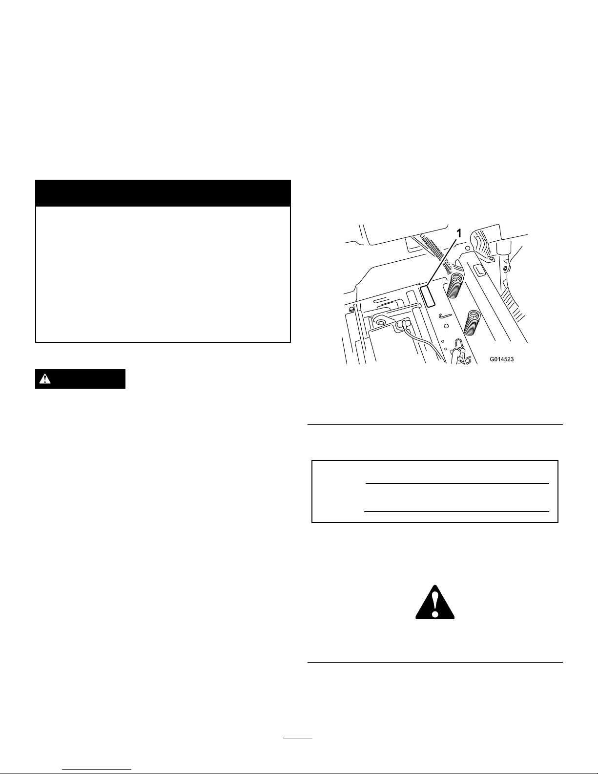
yourproductready .Figure1identiesthelocationofthe
modelandserialnumbersontheproduct.Writethenumbers
inthespaceprovided.
G014523
1
Figure1
Undertheseat
1.Modelandserialnumberplate
Writetheproductmodelandserialnumbersinthespace
below:
ModelNo.
SerialNo.
Thismanualidentiespotentialhazardsandhassafety
messagesidentiedbythesafetyalertsymbol(Figure2),
whichsignalsahazardthatmaycauseseriousinjuryordeath
ifyoudonotfollowtherecommendedprecautions.
Figure2
1.Safetyalertsymbol.
Thismanualuses2wordstohighlightinformation.
Importantcallsattentiontospecialmechanicalinformation
andNoteemphasizesgeneralinformationworthyofspecial
attention.
©2013—TheToro®Company
8111LyndaleAvenueSouth
Bloomington,MN55420
2
Contactusatwww.T oro.com.
PrintedintheUSA.
AllRightsReserved
Page 3

Contents
Introduction..................................................................2
Safety...........................................................................4
SafeOperatingPractices...........................................4
ToroRidingMowerSafety........................................6
SlopeIndicator.......................................................7
SafetyandInstructionalDecals.................................8
ProductOverview.........................................................11
Controls...............................................................11
Operation....................................................................12
AddingFuel...........................................................12
CheckingtheEngine-oilLevel..................................14
BreakinginaNewMachine......................................14
ThinkSafetyFirst...................................................14
StartingtheEngine.................................................15
OperatingtheBlades...............................................16
TestingtheSafety-interlockSystem...........................16
StoppingtheEngine...............................................17
Driving.................................................................17
StoppingtheMachine.............................................19
AdjustingtheHeight-of-Cut....................................19
PositioningtheSeat................................................19
AdjustingtheMotion-controlLevers.........................20
PushingtheMachinebyHand..................................20
OperatingTips......................................................22
Maintenance.................................................................23
RecommendedMaintenanceSchedule(s)......................23
PremaintenanceProcedures........................................23
RaisingtheSeat......................................................23
Lubrication...............................................................24
GreasingtheBearings.............................................24
EngineMaintenance..................................................24
ServicingtheAirCleaner.........................................24
ServicingtheEngineOil..........................................25
ServicingtheSparkPlug..........................................27
FuelSystemMaintenance...........................................28
ReplacingtheIn-lineFuelFilter................................28
ElectricalSystemMaintenance....................................29
ChargingtheBattery...............................................29
ServicingtheFuses.................................................30
DriveSystemMaintenance.........................................31
CheckingtheTirePressure......................................31
ReleasingtheElectricBrake.....................................31
CoolingSystemMaintenance......................................32
CleaningtheEngineScreen......................................32
CleaningtheEngine-coolingFinsand
Shrouds.............................................................32
MowerMaintenance...................................................32
ServicingtheCuttingBlades.....................................32
LevelingtheMowerDeck........................................35
RemovingtheMower..............................................37
InstallingtheMower...............................................38
ReplacingtheGrassDeector..................................38
MowerBeltMaintenance............................................39
ServicingtheMowerBelt.........................................39
Cleaning...................................................................40
WashingtheUndersideoftheMower........................40
Storage........................................................................41
CleaningandStorage..............................................41
Troubleshooting...........................................................42
Schematics...................................................................44
3
Page 4

Safety
Improperuseormaintenancebytheoperatororowner
canresultininjury.Toreducethepotentialforinjury,
complywiththesesafetyinstructions,andpayattentionto
thesafetyalertsymbol,whichmeansCaution,Warning,or
Danger—“personalsafetyinstruction.”Failuretocomply
withtheinstructionsmayresultinpersonalinjuryor
death.
Important:Thismachinewasmanufacturedaccording
totheappropriateregulatorystandardsineffectatthe
timeofmanufacture.Modifyingthismachineinany
waymaycauseittobeoutofcompliancewiththose
standardsandwiththeinstructionsinthisOperator’s
Manual.Modicationstothismachineshouldonlybe
madebyeitherthemanufactureroranAuthorizedT oro
Dealer.
Thisproductiscapableofamputatinghandsandfeet.Follow
allsafetyinstructionstoavoidseriousinjuryordeath.
Theowner/usercanpreventandisresponsibleforaccidents
orinjuriesoccurringtopeople,ordamagetoproperty.
Important:Theadditionofattachmentsmadeby
othermanufacturersthatdonotmeetAmerican
NationalStandardsInstitutecerticationwillcause
noncomplianceofthismachine.
SafeOperatingPractices
Thisproductiscapableofamputatinghandsandfeetand
throwingobjects.Alwaysfollowallsafetyinstructionsto
avoidseriousinjuryordeath.
ThefollowinginstructionsareadaptedfromANSIstandard
B71.1-2012.AllthelanguagewithinthisANSIstandard
appliestothismachine;however,duetotheapplicationof
thestandardacrossmanydifferenttypesofproductssome
statementscanseemgeneralormisleading.Intheseinstances,
Torohasrenedthestatementtoconveythemeaningofthe
standardwhilebettermatchingtheproductthisOperator's
Manualpertains.Safetyinformationinadditiontothe
instructionsfoundintheANSIstandardbelowcanbefound
inToroRidingMowerSafetyattheendofthissection.
GeneralOperation
•Read,understand,andfollowallinstructionsinthe
operator'smanualandonthemachinebeforestarting.
•Donotplacehandsorfeetnearrotatingpartsorunder
themachine.Keepclearofthedischargeopeningatall
times.
•Allowonlyresponsibleadultswhoarefamiliarwiththe
instructionstooperatethemachine.
•Cleartheareaofobjectssuchasrocks,toys,wire,etc.,
whichcouldbepickedupandthrownbytheblade.
•Besuretheareaisclearofotherpeoplebeforemowing.
Stopthemachineifanyoneentersthearea.
•Nevercarrypassengers.
•Donotmowinreverseunlessabsolutelynecessary.
Alwayslookdownandbehindbeforeandwhilebacking
up.
•Beawareofthemowerdischargedirectionanddonot
pointitatanyone.Avoiddischargingmaterialagainsta
wallorobstruction.Materialmayricochetbacktoward
theoperator.Stoptheblade(s)whencrossinggravel
surfaces.
•Donotoperatethemachinewithoutdeector,discharge
coverorentiregrasscollectionsysteminplaceand
working.
•Bealert,slowdownandusecautionwhenmakingturns.
Lookbehindandtothesidebeforechangingdirections.
•Neverleavearunningmachineunattended.Alwaysturn
offblades,setparkingbrake,stopengine,andremovekey
beforedismounting.
•Turnoffbladeswhennotmowing.Stoptheengine,wait
forallpartstocometoacompletestopandremovethe
keybeforecleaningthemachine,removingthegrass
catcheroruncloggingthedischargechute.
•Operatethemachineonlyindaylightorgoodarticial
light.
•Donotoperatethemachinewhileundertheinuence
ofalcoholordrugs.
•Watchfortrafcwhenoperatingnearorcrossing
roadways.
•Useextracarewhenloadingorunloadingthemachine
intoatrailerortruck.
•Alwaysweareyeprotectionwhenoperatingthemower.
•Dataindicatesthatoperators,age60yearsandabove,are
involvedinalargepercentageofridingmower-related
injuries.Operatorsshouldevaluatetheirabilitytooperate
theridingmowersafelyenoughtoprotectthemselvesand
othersfromseriousinjury.
•Alwaysfollowtherecommendationsforanyapplication
ofcounterweights.
•Lightningcancausesevereinjuryordeath.Iflightning
isseenorthunderisheardinthearea,donotoperate
themachine;seekshelter.
SlopeOperation
Slopesareamajorfactorrelatedtolossofcontroland
tip-overaccidents,whichcanresultinsevereinjuryordeath.
Operationonallslopesrequiresextracaution.Ifyoucannot
backuptheslopeorifyoufeeluneasyonit,donotmowit.
•Donotmowslopesgreaterthan15degrees.
•Watchforditches,holes,rocks,dips,andrisesthatchange
theoperatingangle,asroughterraincouldoverturnthe
machine.
•Choosealowgroundspeedsoyouwillnothavetostop
whileoperatingonaslope.
4
Page 5

•Donotmowslopeswhengrassiswet.Slippery
conditionsreducetractionandcouldcauseslidingand
lossofcontrol.
•Alwayskeepthedrivewheelsengagedwhengoingdown
slopes.
•Reducespeedanduseextremecautiononslopes.
•Donotmakesuddenturnsorrapidspeedchanges.
•Removeormarkobstaclessuchasrocks,treelimbs,etc.
fromthemowingarea.Tallgrasscanhideobstacles.
•Avoidsuddenstartswhenmowinguphillbecausethe
mowermaytipbackwards.
•Beawarethatlossoftractionmayoccurgoingdownhill.
Weighttransfertothefrontwheelsmaycausedrive
wheelstoslipandcauselossofbrakingandsteering.
•Alwaysavoidsuddenstartingorstoppingonaslope.If
tireslosetraction,stopthemachine,disengagetheblades
andproceedslowlyofftheslope.
•Useextremecarewithgrasscatchersorotherattachments.
Thesecanchangethestabilityofthemachineandcause
lossofcontrol.
•Donottrytostabilizethemachinebyputtingyourfoot
ontheground.
•Donotmowneardrop-offs,ditches,steepbanksor
water.Wheelsdroppingoveredgescancauserollovers,
whichmayresultinseriousinjury,deathordrowning.
•Useawalkbehindmowerand/orahandtrimmernear
drop-offs,ditches,steepbanksorwater.
Children
Tragicaccidentscanoccuriftheoperatorisnotalerttothe
presenceofchildren.Childrenareoftenattractedtothe
machineandthemowingactivity.Neverassumethatchildren
willremainwhereyoulastsawthem.
•Keepchildrenoutofthemowingareaandunderthe
watchfulcareofanotherresponsibleadult,notthe
operator.
•Bealertandturnthemachineoffifchildrenenterthe
area.
•Beforeandwhilebackingorchangingdirection,look
behind,down,andside-to-sideforsmallchildren.
•Nevercarrychildren,evenwiththebladesoff.Theymay
falloffandbeseriouslyinjuredorinterferewithsafe
machineoperation.
•Childrenwhohavebeengivenridesinthepastmay
suddenlyappearinthemowingareaforanotherrideand
berunoverorbackedoverbythemower.
•Neverallowchildrentooperatethemachine.
•Useextracarewhenapproachingblindcorners,shrubs,
trees,theendofafenceorotherobjectsthatmayobscure
vision.
TowingSafety
•Donotattachtowedequipmentexceptatthehitchpoint.
•Followtheattachmentmanufacturer'srecommendation
forweightlimitsfortowedequipmentandtowingon
slopes.Towedweightmustnotexceedtheweightofthe
machine,operator,andballast.Usecounterweightsor
wheelweightsasdescribedintheattachment,orinthe
pullingmachineOperator’sManual.
•Neverallowchildrenorothersinorontowedequipment.
•Onslopes,theweightofthetowedequipmentmaycause
lossoftraction,increasedriskofrollover,andlossof
control.Reducethetowedweightandslowdown.
•Stoppingdistanceincreaseswiththeweightofthetowed
load.Travelslowlyandallowextradistancetostop.
•Makewideturnstokeeptheattachmentclearofthe
machine.
Service
SafeHandlingofGasoline:
Toavoidpersonalinjuryorpropertydamage,useextracare
whenhandlinggasolineandotherfuels.Theyareammable
andthevaporsareexplosive.
•Extinguishallcigarettes,cigars,pipesandothersources
ofignition.
•Useonlyanapprovedcontainer.
•Neverremovethegascaporaddfuelwhentheengineis
running.Allowtheenginetocoolbeforerefueling.
•Neverrefuelthemachineindoors.
•Neverstorethemachineorfuelcontainerinsidewhere
thereisanopename,suchasnearawaterheateror
furnace.
•Neverllcontainersinsideavehicleoronatruckor
trailerwithaplasticliner.Alwaysplacecontainersonthe
groundawayfromyourvehiclebeforelling.
•Removegas-poweredequipmentfromthetruckortrailer
andrefuelitontheground.Ifthisisnotpossible,then
refuelsuchequipmentwithaportablecontainer,rather
thanfromagasolinedispensernozzle.
•Keepthenozzleincontactwiththerimofthefueltank
orcontaineropeningatalltimesuntilthefuelingis
complete.Donotuseanozzlelock-opendevice.
•Iffuelisspilledonclothing,changeclothingimmediately.
•Neveroverllthefueltank.Replacegascapandtighten
securely.
GeneralService:
•Neveroperateamachineinsideaclosedarea.Engine
exhaustcontainscarbonmonoxide,whichisanodorless,
deadlypoisonthatcankillyou.
•Keepnutsandboltstight,especiallythebladeattachment
bolts.Keepequipmentingoodcondition.
5
Page 6

•Neverinterferewiththeintendedfunctionofasafety
deviceortoreducetheprotectionprovidedbyasafety
device.Checktheirproperoperationregularly.
•Keepthemachinefreeofgrass,leaves,orotherdebris
build-up.Cleanupoilorfuelspillagefuelsoakeddebris.
Allowthemachinetocoolbeforestoring.
•Stopandinspecttheequipmentifyoustrikeanobject.
Repair,ifnecessary,beforerestarting.
•Nevermakeanyadjustmentsorrepairswiththeengine
running.
•Grasscatchercomponentsaresubjecttowear,damage
anddeterioration,whichcouldexposemovingpartsor
allowobjectstobethrown.Frequentlycheckcomponents
andreplacewithmanufacturers'recommendedparts,
whennecessary.
•Mowerbladesaresharpandcancut.Wraptheblade(s)or
weargloves,anduseextracautionwhenservicingthem.
•Checkforproperbrakeoperationfrequently.Adjustand
serviceasrequired.
•Maintainorreplacesafetyandinstructiondecalsas
necessary.
•UseonlygenuineTororeplacementpartstoensurethat
originalstandardsaremaintained.
ToroRidingMowerSafety
ThefollowinglistcontainssafetyinformationspecictoToro
productsorothersafetyinformationthatyoumustknowthat
maynotbeincludedintheANSIstandards.
•Stoptheengine,movethemotioncontrolleversto
neutralandoutwardtotheparkposition,disengagethe
bladecontrolswitch,removethekeyanddisconnectthe
sparkplugwire(s)beforeperforminganyservice,repairs,
maintenanceoradjustments.
•Keephands,feet,hair,andlooseclothingawayfrom
attachmentdischargearea,undersideofmowerandany
movingpartswhileengineisrunning.
•Donottouchequipmentorattachmentpartswhichmay
behotfromoperation.Allowtocoolbeforeattempting
tomaintain,adjustorservice.
•Batteryacidispoisonousandcancauseburns.Avoid
contactwithskin,eyes,andclothing.Protectyourface,
eyes,andclothingwhenworkingwithabattery.
•Batterygasescanexplode.Keepcigarettes,sparksand
amesawayfrombattery.
•UseonlyToroapprovedattachments.Warrantymaybe
voidedifusedwithunapprovedattachments.
•Ifloadingthemachineontoatrailerortruck,useasingle,
full-widthramponly.Therampangleshouldnotexceed
15degrees.
6
Page 7
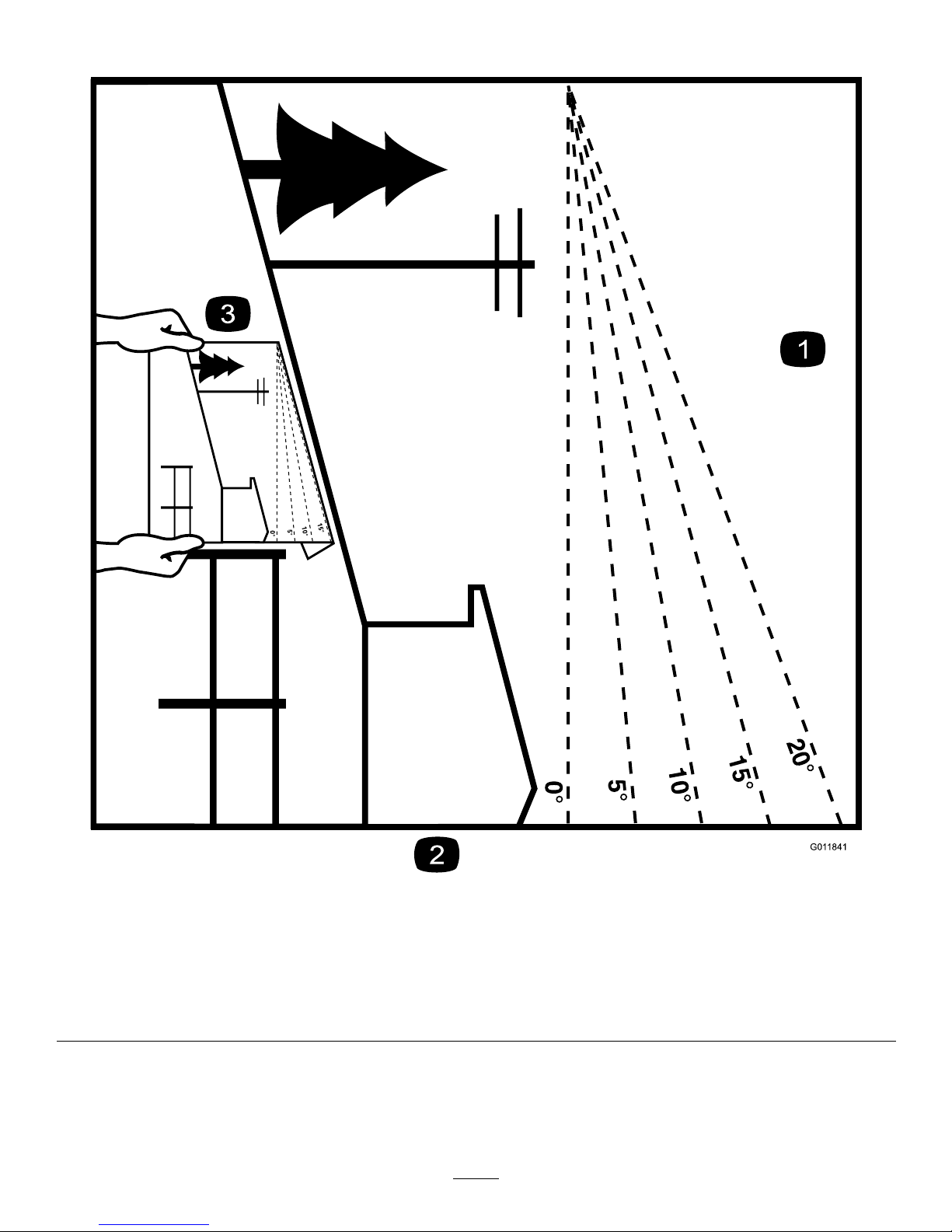
SlopeIndicator
G011841
Figure3
Thispagemaybecopiedforpersonaluse.
1.Themaximumslopeyoucansafelyoperatethemachineonis15degrees.Usetheslopecharttodeterminethedegreeofslope
ofhillsbeforeoperating.Donotoperatethismachineonaslopegreaterthan15degrees.Foldalongtheappropriateline
tomatchtherecommendedslope.
2.Alignthisedgewithaverticalsurface,atree,building,fencepole,etc.
3.Exampleofhowtocompareslopewithfoldededge.
7
Page 8
SafetyandInstructional
Decals
Safetydecalsandinstructionsareeasilyvisibletotheoperatorandarelocatednearanyareaofpotential
danger.Replaceanydecalthatisdamagedorlost.
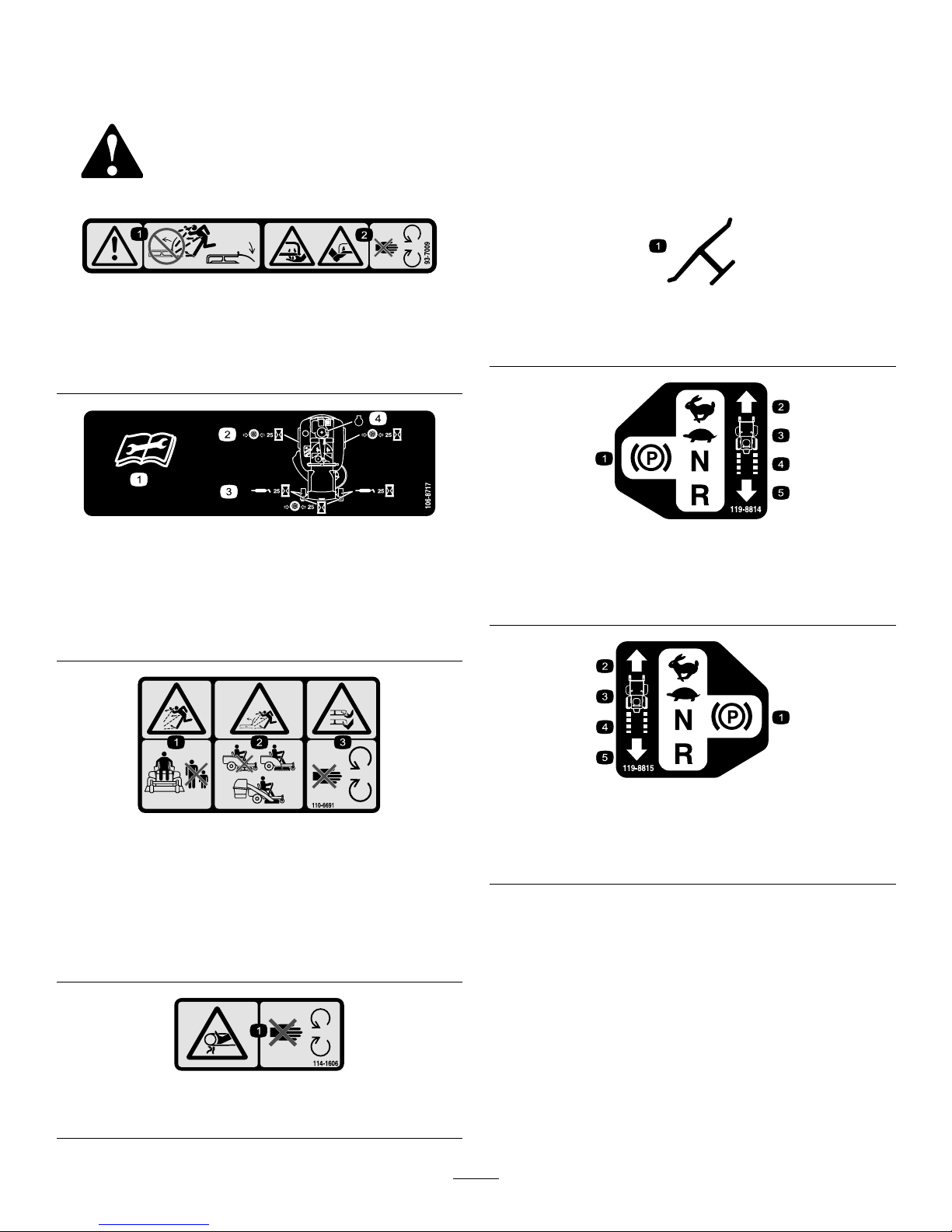
93-7009
1.Warning—don'toperatethemowerwiththedeectorupor
removed;keepthedeectorinplace.
2.Cutting/dismembermenthazardofhandorfoot,mower
blade—stayawayfrommovingparts.
106-8717
1.Readtheinstructionsbeforeservicingorperforming
maintenance.
2.Checktirepressureevery25operatinghours.
3.Greaseevery25operatinghours.
4.Engine
110-6691
1.Thrownobjecthazard—keepbystandersasafedistance
fromthemachine.
2.Thrownobjecthazard,mower—donotoperatewithoutthe
deector,dischargecover,orgrasscollectionsystemin
place.
3.Cutting/dismembermentofhandorfoot—stayawayfrom
movingparts.
114-1606
1.Entanglementhazard,belt—keepallguardsinplace.
Manufacturer'sMark
1.Indicatesthebladeisidentiedasapartfromtheoriginal
machinemanufacturer.
119-8814
1.Parkingposition4.Neutral
2.Fast5.Reverse
3.Slow
119-8815
1.Parkingposition4.Neutral
2.Fast5.Reverse
3.Slow
8
Page 9
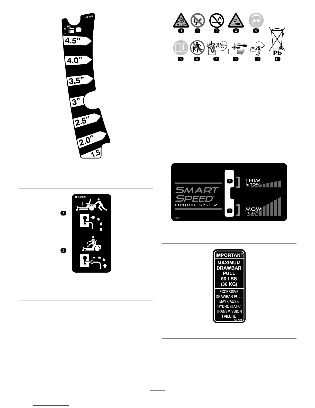
119-8871
42InchModel
1.Height-of-cut
121-2989
1.Bypassleverpositionfor
pushingthemachine
2.Bypassleverpositionfor
operatingthemachine
BatterySymbols
Someorallofthesesymbolsareonyourbattery
1.Explosionhazard
6.Keepbystandersasafe
distancefromthebattery .
2.Nore,opename,or
smoking.
7.Weareyeprotection;
explosivegasescan
causeblindnessandother
injuries
3.Causticliquid/chemical
burnhazard
8.Batteryacidcancause
blindnessorsevereburns.
4.Weareyeprotection9.Flusheyesimmediately
withwaterandgetmedical
helpfast.
5.ReadtheOperator's
Manual.
10.Containslead;donot
discard.
130-0780
1.Slow(trimandtow)2.Fast(mowandgo)
109-7076
9
Page 10
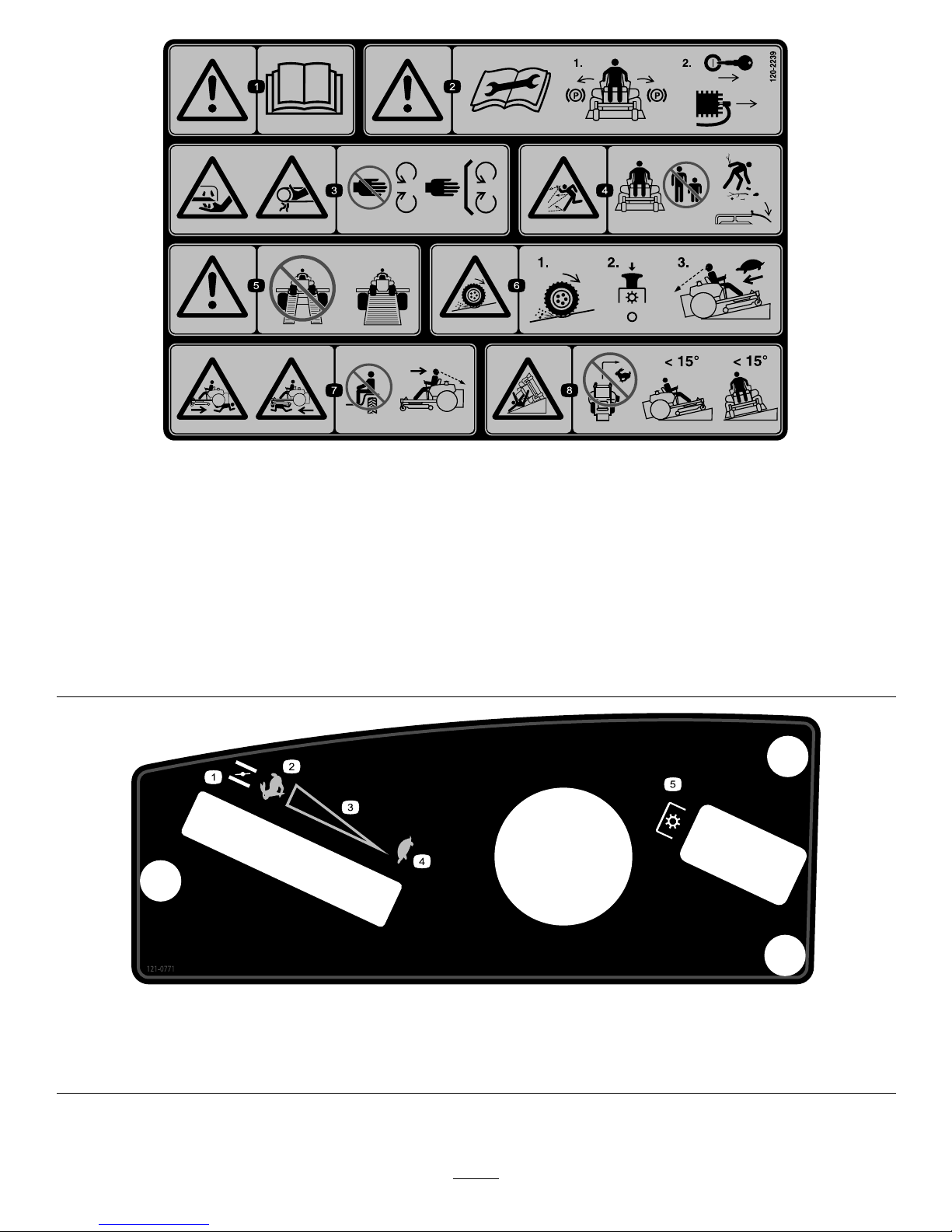
120-2239
1.Warning—readtheOperator'sManual.5.Warning—donotusesplitramps,useafullrampswhen
transportingmachine.
2.Warning—readtheinstructionsbeforeservicingorperforming
maintenance;movethemotioncontrolleverstothepark
(brake)position,removetheignitionkeyanddisconnectthe
sparkplugwire.
6.Lossoftraction/controlhazard,slopes—lossoftraction/control
onaslope,disengagethebladecontrolswitch(PTO),
proceedofftheslopeslowly .
3.Cutting/dismembermenthazard,mowerblade;entanglement
hazard,belt—stayawayfrommovingparts,keepallguards
andshieldsinplace.
7.Crushing/dismembermenthazardofbystanders,reversing;
crushing/dismembermenthazardofbystanders—donotcarry
passengers,lookbehindanddownwhenreversing.
4.Thrownobjecthazard—keepbystandersasafedistancefrom
themachine,pickupdebrisbeforeoperating,keepdeector
inplace.
8.Tippinghazard—donotmowslopesgreaterthan15degrees,
avoidsuddenandsharpturnswhileonslopes.
121-0771
1.Choke4.Slow
2.Fast
5.Powertake-off(PTO),Bladecontrolswitch
3.Continuousvariablesetting
10
Page 11
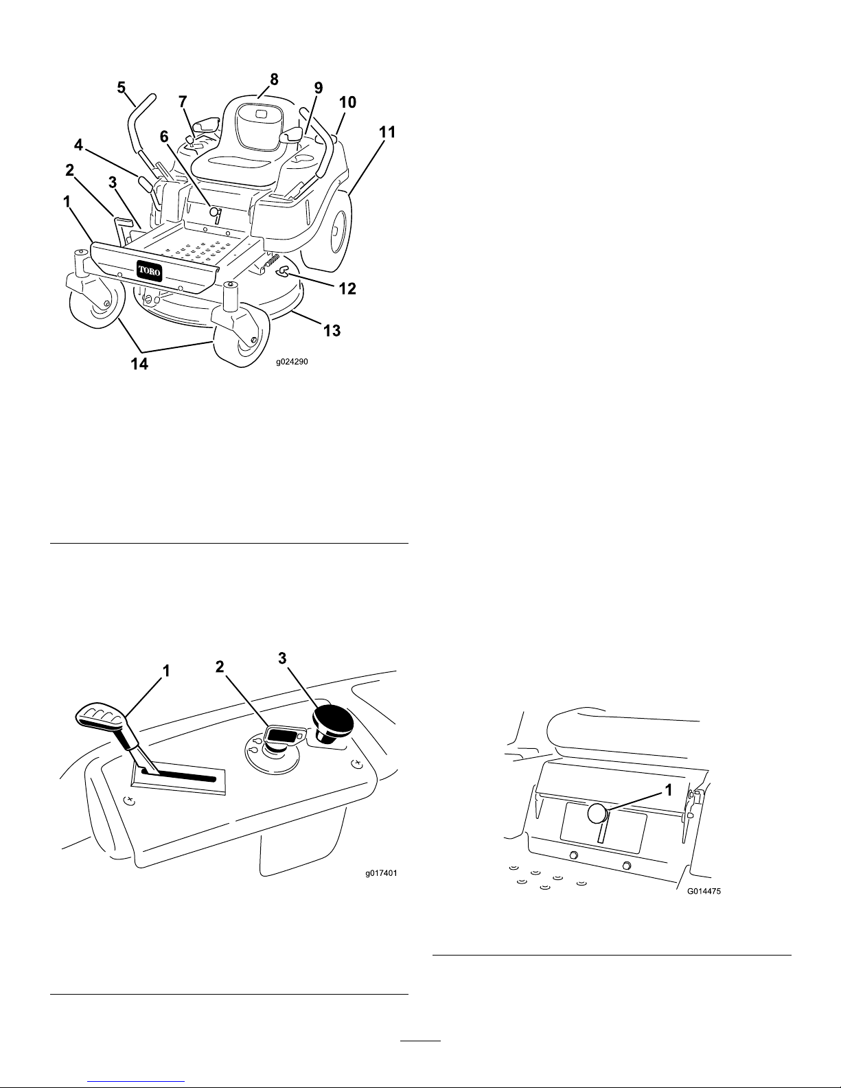
ProductOverview
Figure4
1.Footrest
8.Operatorseat
2.Foot-assistpedal9.Engine
3.Deector
10.Fuel-tankcap
4.Height-of-cutlever
11.Reardrivewheel
5.Motion-controllever
12.Washouttting
6.Smart-speedlever
13.Mowerdeck
7.Controlpanel
14.Frontcasterwheels
Controls
BecomefamiliarwithallofthecontrolsinFigure4and
Figure5beforeyoustarttheengineandoperatethemachine.
Figure5
ControlPanel
1.Throttle/Choke
3.Blade-controlswitch
(powertake-off)
2.Ignitionswitch
IgnitionSwitch
Theignitionswitchhas3positions:Off,Run,andStart.The
keywillturntoStartandmovebacktoRunuponrelease.
TurningthekeytotheOffpositionwillstoptheengine;
however,alwaysremovethekeywhenleavingthemachine
topreventsomeonefromaccidentallystartingtheengine
(Figure5).
Throttle/ChokeControl
Thethrottleandchokeiscombinedintoonecontrollever.
Thethrottlecontrolstheenginespeedandithasacontinuous
variablesettingfromSlowtoFast.Engagethechokeby
movingtheleverpasttheFastsettinguntilitstops(Figure5).
Blade-controlSwitch(PowerTake-Off)
Theblade-controlswitch,representedbyapowertake-off
(PTO)symbol,engagesanddisengagespowertothemower
blades(Figure5).
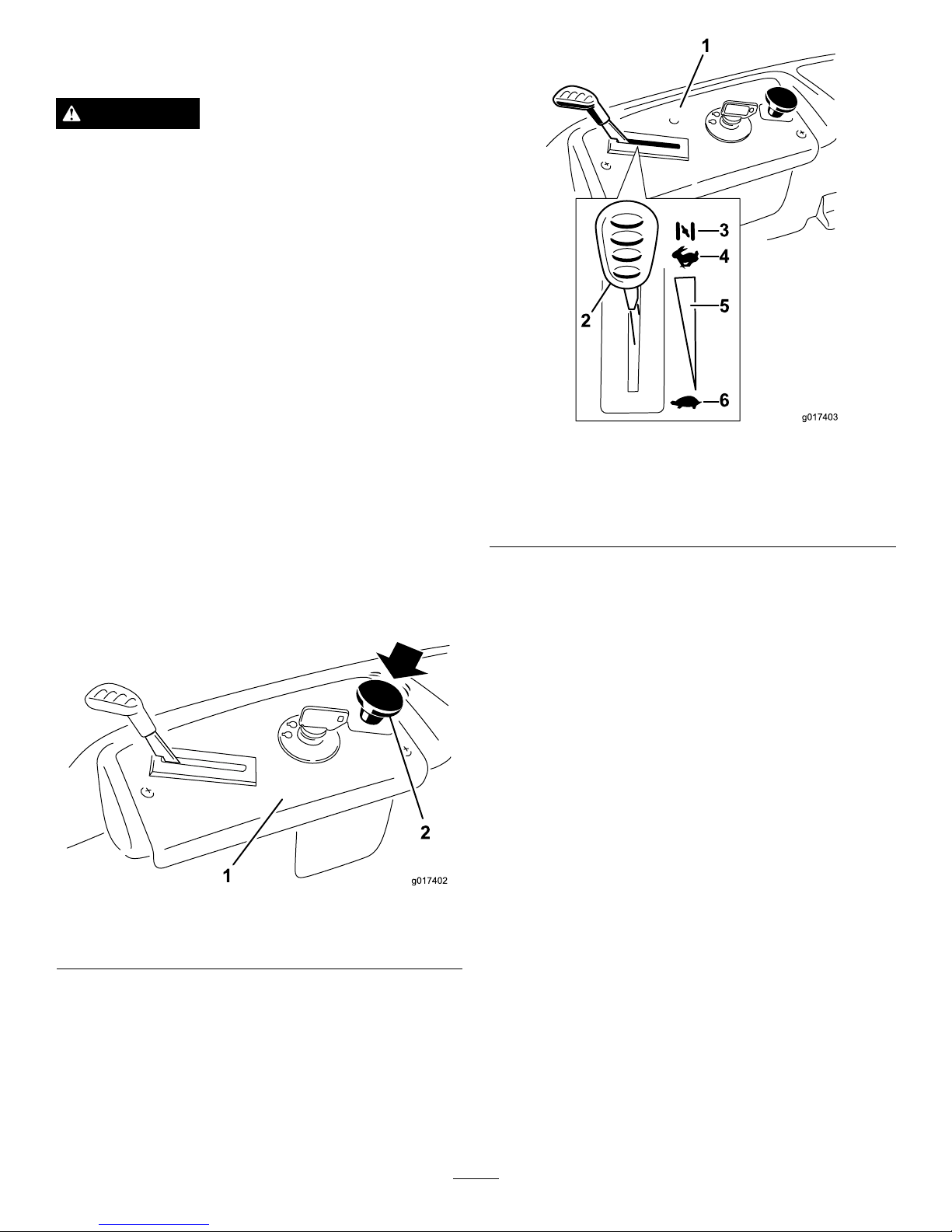
Motion-controlLeversandPark
Position
Themotion-controlleversarespeed-sensitivecontrolsof
independent-wheelmotors.Movingaleverforwardor
backwardturnsthewheelonthesamesideforwardorin
reverse;wheelspeedisproportionaltotheamountthelever
ismoved.Movethecontrolleversoutwardfromthecenter
totheparkpositionandexitthemachine(Figure17).Always
positionthemotion-controlleversintotheparkposition
whenyoustopthemachineorleaveitunattended.
SmartSpeed™ControlSystemLever
TheSmartSpeed™ControlSystemlever,locatedbelowthe
operatingposition,givestheoperatorachoicetodrivethe
machineat2speedranges—highandlow(Figure6).
G014475
1
Figure6
1.Smartspeedlever
11
Page 12
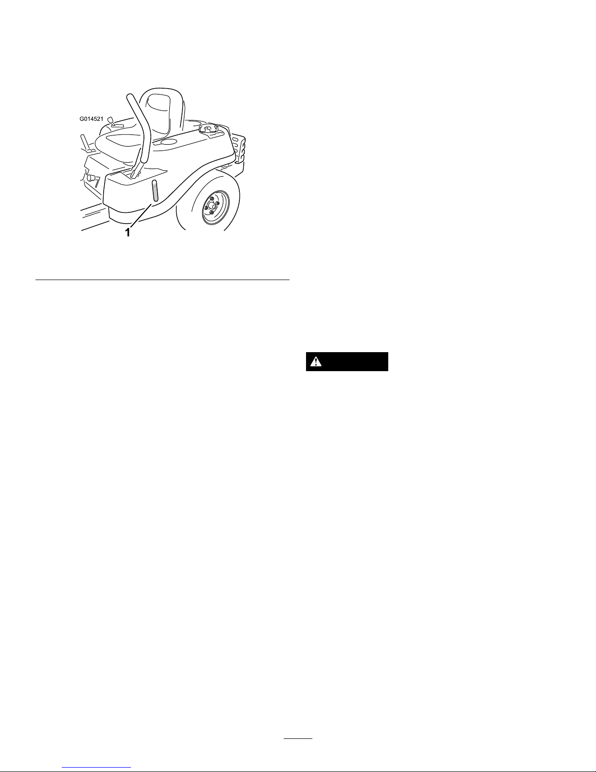
Fuel-presenceWindow
Thefuelwindowlocatedontheleft-handsideofthemachine,
canbeusedtoverifythepresenceofgasolineinthetank
(Figure7).
G014521
1
Figure7
1.Fuel-presencewindow
Height-of-CutLever
Theheight-of-cutleverallowstheoperatortolowerand
raisethedeckfromtheseatedposition.Whentheleveris
movedup(towardtheoperator),thedeckisraisedfromthe
ground,andwhenmoveddown(awayfromtheoperator),it
isloweredtowardtheground.Onlyadjusttheheight-of-cut
whilethemachineisnotmoving(Figure4).
Operation
Note:Determinetheleftandrightsidesofthemachine
fromthenormaloperatingposition.
AddingFuel
•Forbestresults,useonlyclean,fresh(lessthan30days
old),unleadedgasolinewithanoctaneratingof87or
higher((R+M)/2ratingmethod).
•Ethanol:Gasolinewithupto10%ethanol(gasohol)
or15%MTBE(methyltertiarybutylether)byvolume
isacceptable.EthanolandMTBEarenotthesame.
Gasolinewith15%ethanol(E15)byvolumeisnot
approvedforuse.Neverusegasolinethatcontains
morethan10%ethanolbyvolume,suchasE15
(contains15%ethanol),E20(contains20%ethanol),or
E85(containsupto85%ethanol).Usingunapproved
gasolinemaycauseperformanceproblemsand/orengine
damagewhichmaynotbecoveredunderwarranty.
•Donotusegasolinecontainingmethanol.
•Donotstorefueleitherinthefueltankorfuelcontainers
overthewinterunlessafuelstabilizerisused.
•Donotaddoiltogasoline.
DANGER
Incertainconditions,gasolineisextremely
ammableandhighlyexplosive.Areorexplosion
fromgasolinecanburnyouandothersandcan
damageproperty.
•Fillthefueltankoutdoors,inanopenarea,
whentheengineiscold.Wipeupanygasoline
thatspills.
•Neverllthefueltankinsideanenclosedtrailer.
•Donotllthefueltankcompletelyfull.Add
gasolinetothefueltankuntilthelevelis6to13
mm(1/4to1/2inch)belowthebottomofthe
llerneck.Thisemptyspaceinthetankallows
gasolinetoexpand.
•Neversmokewhenhandlinggasoline,andstay
awayfromanopenameorwheregasoline
fumesmaybeignitedbyaspark.
•Storegasolineinanapprovedcontainerand
keepitoutofthereachofchildren.Neverbuy
morethana30-daysupplyofgasoline.
•Donotoperatewithoutentireexhaustsystemin
placeandinproperworkingcondition.
12
Page 13
DANGER
Incertainconditionsduringfueling,static
electricitycanbereleasedcausingasparkwhich
canignitethegasolinevapors.Areorexplosion
fromgasolinecanburnyouandothersandcan
damageproperty.
•Alwaysplacegasolinecontainersontheground
awayfromyourvehiclebeforelling.
•Donotllgasolinecontainersinsideavehicleor
onatruckortrailerbedbecauseinteriorcarpets
orplastictruckbedlinersmayinsulatethe
containerandslowthelossofanystaticcharge.
•Whenpractical,removegas-poweredequipment
fromthetruckortrailerandrefueltheequipment
withitswheelsontheground.
•Ifthisisnotpossible,thenrefuelsuch
equipmentonatruckortrailerfromaportable
container,ratherthanfromagasolinedispenser
nozzle.
•Ifagasolinedispensernozzlemustbeused,
keepthenozzleincontactwiththerimofthe
fueltankorcontaineropeningatalltimesuntil
fuelingiscomplete.
WARNING
Gasolineisharmfulorfatalifswallowed.Long-term
exposuretovaporscancauseseriousinjuryand
illness.
•Avoidprolongedbreathingofvapors.
•Keepfaceawayfromnozzleandgastankor
conditionerbottleopening.
•Avoidcontactwithskin;washoffspillagewith
soapandwater.
UsingStabilizer/Conditioner
Useafuelstabilizer/conditionerinthemachinetoprovide
thefollowingbenets:
•Keepsgasolinefreshduringstorageof90daysorless.
Forlongerstorageitisrecommendedthatthefueltank
bedrained.
•Cleanstheenginewhileitruns
•Eliminatesgum-likevarnishbuildupinthefuelsystem,
whichcauseshardstarting
Important:Donotusefueladditivescontaining
methanolorethanol.
Addthecorrectamountofgasstabilizer/conditionerto
thegas.
Note:Afuelstabilizer/conditionerismosteffective
whenmixedwithfreshgasoline.Tominimizethechance
ofvarnishdepositsinthefuelsystem,usefuelstabilizer
atalltimes.
FillingtheFuelTank
Ensurethattheengineisshutoffandthemotioncontrolsare
intheparkedposition.
Important:Donotoverllfueltank.Fillthefueltank
tothebottomofthellerneck.Theemptyspaceinthe
tankallowsthefueltoexpand.Overllingmayresultin
fuelleakage,damagetotheengine,ordamagetothe
emissionssystem.
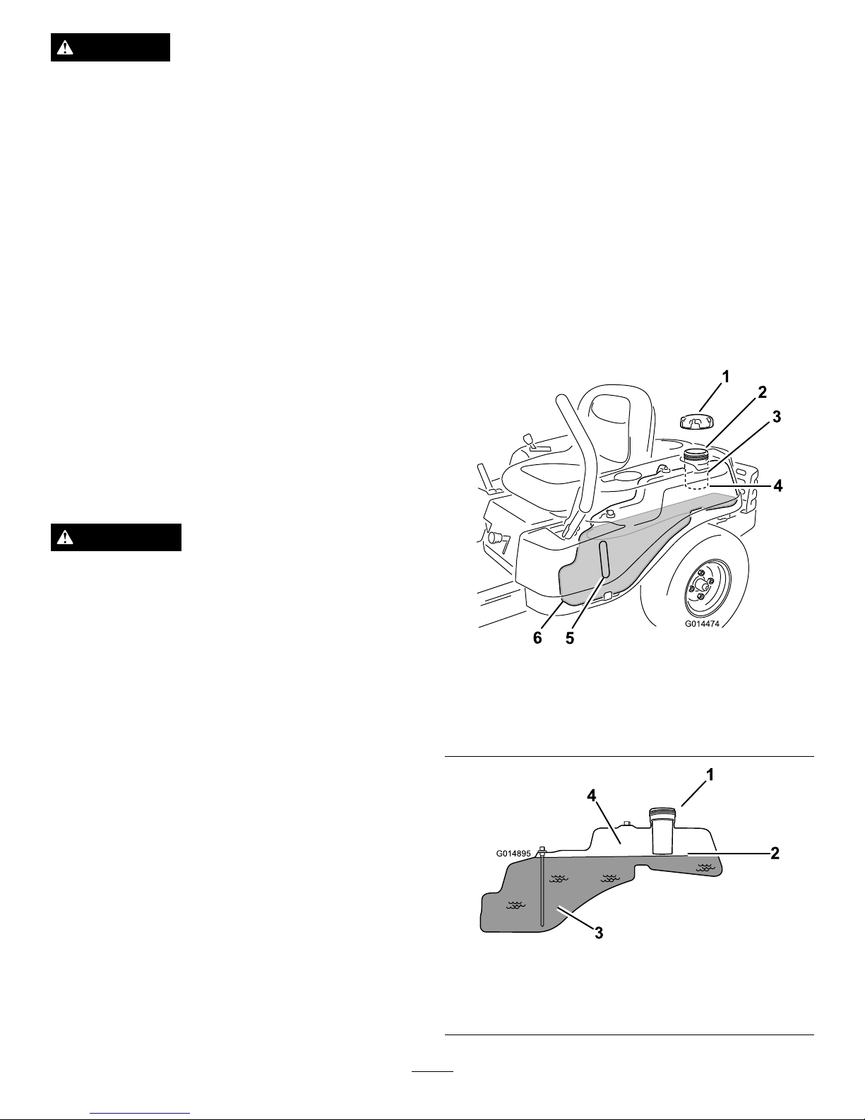
1.Cleanaroundthefuel-tankcapandremovethecap.
Note:Youcanusethefuelwindowtoverifythe
presenceofgasolinebeforellingthetank(Figure8).
2.Slowlyaddgasolineuntilthefuelreachesthebaseof
thellerneck(Figure8).
G014474
1
2
3
4
5
6
Figure8
1.Fuel-tankcap
4.Baseofthellerneck(do
notllpasthere)
2.Fillopening5.Fuelwindow
3.Fillerneck
6.Endofthefueltank
G014895
1
2
3
4
Figure9
1.Fillopening3.Fuel
2.Baseofthellerneck(do
notllpasthere)
4.Emptyspace(forfuel
expansion)
13
Page 14
3.Installthefuel-tankcapsecurely,andtightenuntilit
clicks.
CheckingtheEngine-oilLevel
Beforeyoustarttheengineandusethemachine,checktheoil
levelintheenginecrankcase;refertoCheckingtheEngine-oil
Level(page25).
BreakinginaNewMachine
Newenginestaketimetodevelopfullpower.Mowerdecks
anddrivesystemshavehigherfrictionwhennew,placing
additionalloadontheengine.Allow40to50hoursof
break-intimefornewmachinestodevelopfullpowerand
bestperformance.
ThinkSafetyFirst
OperatingSafety
Pleasecarefullyreadallofthesafetyinstructionsanddecals
inthesafetysection.Knowingthisinformationcouldhelp
you,yourfamily,pets,orbystandersavoidinjury.
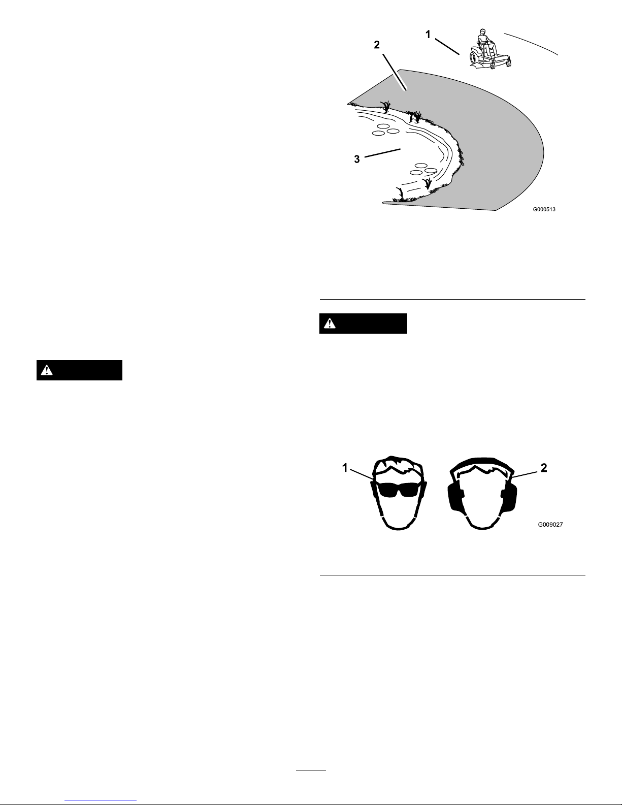
DANGER
Mowingonwetgrassorsteepslopescancause
slidingandlossofcontrol.
Wheelsdroppingoveredgescancauserollovers,
whichmayresultinseriousinjury,death,or
drowning.
Alossoftractionisalossofsteeringcontrol.
Toavoidlossofcontrolandpossibilityofrollover:
•Donotmowneardrop-offsornearwater.
•Donotmowslopesgreaterthan15degrees.
•Reducethespeedanduseextremecautionon
slopes.
•Whenmowingslopes,graduallyworkfrom
lowertohigherareasontheincline.
•Avoidsuddenturnsorrapidspeedchanges.
•Turnup,intoaninclinewhenchanging
directionsonslopes.Turningdowntheslope
reducestraction.
•Attachmentschangethehandlingcharacteristics
ofthemachine.Useextracautionwhenusing
attachmentswiththemachine.
Figure10
1.Safezone—usethe
TimeCutterhere
3.Water
2.Useawalk-behindmower
and/orhandtrimmernear
drop-offsandwater .
CAUTION
Thismachineproducessoundlevelsinexcessof85
dBAattheoperatorsearandcancausehearingloss
throughextendedperiodsofexposure.
Wearhearingprotectionwhenoperatingthis
machine.
Theuseofprotectiveequipmentforeyes,ears,feet,andhead
isrecommended.
G009027
1
2
Figure11
1.Wearsafetyglasses
2.Wearhearingprotection
14
Page 15
UnderstandingtheSafety-interlock
System
WARNING
Ifsafety-interlockswitchesaredisconnectedor
damaged,themachinecouldoperateunexpectedly
causingpersonalinjury.
•Donottamperwiththeinterlockswitches.
•Checktheoperationoftheinterlockswitches
daily,andreplaceanydamagedswitchesbefore
operatingthemachine.
Thesafety-interlocksystemisdesignedtopreventtheengine
fromstartingunless:
•Thebladesaredisengaged.
•Themotion-controlleversareintheparkposition.
Thesafety-interlocksystemalsoisdesignedtostoptheengine
wheneverthecontrolleversareoutoftheparkpositionand
yourisefromtheseat.
StartingtheEngine
1.Sitdownontheseat,andmovethemotioncontrols
outwardtotheparkposition.
2.Disengagethebladesbymovingtheblade-control
switchtoOff(Figure12).
Figure12
1.Controlpanel2.Blade-controlswitch—Off
position
3.MovethethrottlelevertoChokebeforestartingacold
engine(Figure13).
Note:Itmaybenecessarytoholdtheleveragainst
thestop,inthechokeposition,whiletryingtostart
theengine.
Note:Awarmorhotenginemaynotrequirechoking.
Figure13
1.Controlpanel
4.Fast
2.Throttle/choke
lever—chokeposition
5.Continuous-variable
setting
3.Choke6.Slow
4.TurntheignitionkeytoStarttoenergizethestarter
(Figure14).
Note:Whentheenginestarts,releasethekey.
Important:Donotengagethestarterformore
than10secondsatatime.Iftheenginefailsto
start,allowa60-secondcool-downperiodbetween
attempts.Failuretofollowtheseinstructionscan
damagethestartermotor.
15
Page 16

Figure14
1.Controlpanel4.Off
2.Ignitionkey—runposition5.Run
3.Ignitionkey—startposition
6.Start
5.Aftertheenginestarts,movethethrottlelevertoFast
(Figure13).
Note:Iftheenginestallsorhesitates,movethe
throttleleverbacktoChokeforafewseconds.Repeat
thisasrequired.
OperatingtheBlades
Theblade-controlswitch,representedbyapowertake-off
(PTO)symbol,engagesanddisengagespowertothemower
blades.Thisswitchcontrolspowertoanyattachmentsthat
drawpowerfromtheengine,includingthemowerdeckand
cuttingblades.
EngagingtheBlades
Important:Donotengagethebladeswhenparkedin
tallgrass;beltorclutchdamagecanoccur.
1.Releasethepressureonthemotion-controllevers,and
placethemachineinneutral.
2.MovethethrottletotheFastposition.
Note:Alwaysengagethebladeswiththethrottlein
theFastposition.
3.Pullupontheblade-controlswitchtomoveittothe
Onposition,andengagetheblades(
Figure15).
Figure15
1.Controlpanel2.Blade-controlswitch—On
position
DisengagingtheBlades
Pushdownontheblade-controlswitchtomoveittotheOff
position,anddisengagetheblades(Figure16).
Figure16
1.Controlpanel2.Blade-controlswitch—Off
TestingtheSafety-interlock
System
Testthesafety-interlocksystembeforeyouusethemachine
eachtime.Ifthesafetysystemdoesnotoperateasdescribed
below,haveanAuthorizedServiceDealerrepairthesafety
systemimmediately.
1.Whilesittingontheseat,withthecontrolleversinpark
position,andmovetheblade-controlswitchtoOn.
2.Trystartingtheengine;theengineshouldnotcrank.
3.Whilesittingontheseat,movetheblade-control
switchtoOff.
4.Moveeithermotion-controllevertothecenter,
unlockedposition.
5.Trystartingtheengine;theengineshouldnotcrank.
16
Page 17

6.Repeatwiththeothermotion-controllever.
7.Whilesittingontheseat,movetheblade-control
switchtoOff,andlockthemotion-controlleversin
theparkposition.
8.Starttheengine.
9.Whiletheengineisrunning,engagetheblade-control
switch,andriseslightlyfromtheseat.
Note:Theengineshouldstop.
10.Whilesittingontheseat,movetheblade-control
switchtoOff,andlockthemotion-controlleversin
theparkposition.
11.Starttheengine.
12.Whiletheengineisrunning,movethemotion-control
leverstothecenter,unlockedposition,engagethe
blade-controlswitch,andriseslightlyfromtheseat.
Note:Theengineshouldstop.
StoppingtheEngine
1.Disengagethebladesbymovingtheblade-control
switchtoOff(Figure16).
2.MovethethrottlelevertotheSlowposition.
3.Lowertheenginespeedtotheidlespeed.
Note:Runitatidlespeedforapproximatelyone
minute.
4.TurntheignitionkeytoOff(
Figure14)andremove
thekey.
Driving
Drivingthemachinebenetsfromanunderstandingof
whatzero-turn-radiusmowermeans.Thedrivewheelsturn
independently,poweredbyhydraulicmotorsoneachaxle;
henceonesidecanturninreversewhiletheotherturns
forwardcausingthemachinetospinratherthanturn.This
vastlyimprovesthemachinemaneuverabilitybutmayrequire
someadjustmentiftheoperatorisunfamiliar.
WARNING
Themachinecanspinveryrapidly .Theoperator
maylosecontrolofthemachineandcausepersonal
injuryordamagetothemachine.
•Usecautionwhenmakingturns.
•Slowthemachinedownbeforemakingsharp
turns.
Thethrottlecontrolregulatestheenginespeedasmeasured
inrpm(revolutionsperminute).Placingthethrottlecontrol
intheFastpositioncanbebestforperformance.Formost
applications,operatinginthefull-throttlepositionisdesirable.
Figure17
1.Park(brake)position
3.Forward
2.Center,unlockposition
4.Backward
17
Page 18

UsingtheSmartSpeed™Control
System
TheSmartSpeed™Control-Systemlever,locatedbelowthe
operatingposition(Figure18),givestheoperatorachoiceto
drivethemachineat2groundspeedranges—highandlow .
G014475
1
Figure18
1.Smart-speedlever
Tochangespeeds:
1.Movethemotioncontrolleverstoneutralandoutward
totheparkposition;disengagethebladecontrolswitch.
WARNING
Removingyourhandsfromthemotion-control
leverswhilethemachineisinmotioncan
resultinalossofcontrolcausingharmtoyou
orbystanders.
Alwaysstopthemachineandmovethe
motion-controlleverstotheparkposition
beforeadjustingtheSmartSpeed™Control
System.
2.Adjustthelevertothedesiredposition.
DrivingForward
1.Movetheleverstothecenter,unlockedposition.
2.Togoforward,slowlypushthemotion-controllevers
forward(Figure17).
G008952
Figure19
Togostraight,applyequalpressuretoboth
motion-controllevers(Figure17).
Toturn,releasepressureonthemotion-controllever
towardthedirectionyouwanttoturn(Figure17).
Thefartheryoumovethemotion-controlleversin
eitherdirection,thefasterthemachinewillmovein
thatdirection.
Tostop,pullthemotion-controlleverstoneutral.
18
Page 19

DrivingBackward
1.Movetheleverstothecenter,unlockedposition.
2.Togobackward,lookbehindyouanddown,asyou
slowlypullthemotion-controlleversrearward(Figure
20).
G008953
Figure20
Togostraight,applyequalpressuretoboth
motion-controllevers(Figure20).
Toturn,releasethepressureonthemotion-control
levertowardthedirectionyouwanttoturn.
Tostop,pushthemotion-controlleverstoneutral.
StoppingtheMachine
Tostopthemachine,movethemotion-controlleversto
neutralandoutwardtotheparkposition,disengagethe
blade-controlswitch,ensurethethrottleisintheFast
position,andturntheignitionkeytooff.
Note:Remembertoremovethekeyfromtheignitionswitch.
WARNING
Childrenorbystandersmaybeinjuredifthey
moveorattempttooperatethemowerwhileitis
unattended.
Alwaysremovetheignitionkeyandmovethe
motion-controlleversoutwardtotheparkposition
whenleavingthemachineunattended,evenifjust
forafewminutes.
AdjustingtheHeight-of-Cut
Height-of-cutiscontrolledbytheleverlocatedtotherightof
theoperatingposition(Figure21).
G014476
1
2
3
Figure21
1.Height-of-cutlever3.115mm(4.5
inches)—transport
position
2.Height-of-cutpositions
1.Pullupandinwardonthelevertomoveittothe
desiredcuttingposition.
2.Onceatthedesiredcuttingposition,slowlylowerthe
leveruntilitengagestheposition.
Note:Thetransportpositionisthehighestheight-of-cut
positionorcuttingheight(115mm(4.5inches))asshown
inFigure21.
PositioningtheSeat
1.Raisetheseatandloosentheadjustmentboltsjust
enough,sothattheseatcanmove(Figure22).
G014477
1
Figure22
1.Adjustmentbolt
2.Movetheseattothedesiredposition,andtightenthe
bolts.
19
Page 20

AdjustingtheMotion-control
Levers
AdjustingtheHeight
Themotion-controlleverscanbeadjustedhigherorlowerfor
maximumoperatorcomfort.
1.Removethe2boltsholdingthecontrollevertothe
control-armshaft(Figure23).
2.Movethecontrollevertothenextsetofholes.
3.Securetheleverwiththe2bolts(Figure23).
4
1
2
G014970
3
Figure23
1.Control-armshaft3.Slotted,upperhole
2.Controllever
4.Bolt
4.Repeattheadjustmentfortheoppositecontrollever.
AdjustingtheTilt
Themotion-controlleverscanbetiltedforeoraftfor
maximumoperatorcomfort.
1.Loosentheupperboltholdingthecontrollevertothe
control-armshaft.
2.Loosenthelowerboltjustenoughtopivotthecontrol
leverforeoraft(Figure23).Tightenbothboltsto
securethecontrolinthenewposition.
3.Repeattheadjustmentfortheoppositecontrollever.
PushingtheMachinebyHand
Important:Alwayspushthemachinebyhand.Donot
towthemachine,becausedamagemayoccur.
Thismachinehasanelectric-brakemechanism,andtopush
themachine,theignitionkeyneedstobeintheRunposition.
Thebatteryneedstobechargedandfunctioningforthe
electricbraketobedisengage.
PushingtheMachine
1.Parkthemachineonalevelsurface,anddisengagethe
blade-controlswitch.
2.Movethemotion-controlleversoutwardtothepark
position,stoptheengine,andwaitforallmovingparts
tostopbeforeleavingtheoperatingposition.
3.Locatethebypassleversontheframeonbothsidesof
theengine.
4.Movethebypassleversforwardthroughthekeyhole
anddowntolocktheminplace(Figure24).
Note:Ensurethisisdoneforeachlever.
5.Movethemotion-controlleversinwardtotheneutral
positionandturntheignitionkeytotheRunposition.
Note:Donotstartthemachine.
Note:Themachineisnowabletobepushedbyhand.
20
Page 21

g017303
1 2
3
Figure24
1.Bypass-leverlocations
3.Leverpositionforpushing
themachine
2.Leverpositionfor
operatingthemachine
6.Whennished,ensurethatthekeyhasbeenreturnedto
theStoppositiontoavoiddrainingthebatterycharge.
Note:Ifthemachinefailstomove,theelectricbrakemay
stillbeengaged.Ifnecessary,theelectricbrakecanbereleased
manually;refertoReleasingtheElectricBrake(page31).
OperatingtheMachine
Movethebypassleversrearwardthroughthekeyholeand
downtolocktheminplaceasshowninFigure24.
Note:Ensurethisisdoneforeachlever.
21
Page 22

OperatingTips
UsingtheFastThrottleSetting
Forbestmowingandmaximumaircirculation,operate
theengineattheFastthrottleposition.Airisrequiredto
thoroughlycutgrassclippings,sodonotsettheheight-of-cut
solowastototallysurroundthemowerbyuncutgrass.
Alwaystrytohaveonesideofthemowerfreefromuncut
grass,whichallowsairtobedrawnintothemower.
UsingtheSmartSpeed™Control
System
TheSmartSpeed™Control-Systemlever,locatedbelow
theoperatingposition,givestheoperatorachoicetodrive
themachineat2speedranges—highandlow.Anoperator
canbenetfromthelowerspeedsettingwhenmaneuvering
themachineintightspacesoroperatingarounddelicate
landscapes.Thelowsettingcanalsobeusedtooperatethe
machineatahighthrottlesettingandbladespeed,whilestill
beingabletoreducethegroundspeedtoincreasethequality
ofcut.
CuttingaLawnfortheFirstTime
Cutgrassslightlylongerthannormaltoensurethatthe
cuttingheightofthemowerdoesnotscalpanyuneven
ground.However,thecuttingheightusedinthepastis
generallythebestonetouse.Whencuttinggrasslongerthan
sixinchestall,youmaywanttocutthelawntwicetoensure
anacceptablequalityofcut.
Cutting1/3oftheGrassBlade
Itisbesttocutonlyabout1/3ofthegrassblade.Cutting
morethanthatisnotrecommendedunlessgrassissparse,or
itislatefallwhengrassgrowsmoreslowly.
MowingDirection
Alternatethemowingdirectiontokeepthegrassstanding
straight.Thisalsohelpsdisperseclippingswhichenhances
decompositionandfertilization.
MowingatCorrectIntervals
Normally,mowevery4days.But,remember,grassgrowsat
differentratesatdifferenttimes.Sotomaintainthesame
cuttingheight,whichisagoodpractice,andmowmoreoften
inearlyspring.Asthegrassgrowthrateslowsinmidsummer,
mowlessfrequently .Ifyoucannotmowforanextended
period,rstmowatahighcuttingheight,thenmowagain2
dayslateratalowerheightsetting.
AvoidingCuttingTooLow
Ifthecuttingwidthofthemoweriswiderthanthemower
youpreviouslyused,raisethecuttingheighttoensurethat
uneventurfisnotcuttooshort.
CuttingLongGrass
Ifthegrassiseverallowedtogrowslightlylongerthan
normal,orifitcontainsahighdegreeofmoisture,raisethe
cuttingheighthigherthanusualandcutthegrassatthis
setting.Thencutthegrassagainusingthelower,normal
setting.
Stopping
Ifthemachine'sforwardmotionmustbestoppedwhile
mowing,aclumpofgrassclippingsmaydropontoyour
lawn.Toavoidthis,moveontoapreviouslycutareawiththe
bladesengagedoryoucandisengagethemowerdeckwhile
movingforward.
KeepingtheUndersideoftheMower
Clean
Cleanclippingsanddirtfromtheundersideofthemower
aftereachuse.Ifgrassanddirtbuildupinsidethemower,
cuttingqualitywilleventuallybecomeunsatisfactory.
MaintainingtheBlade(s)
Maintainasharpbladethroughoutthecuttingseasonbecause
asharpbladecutscleanlywithouttearingorshreddingthe
grassblades.Tearingandshreddingturnsgrassbrownat
theedges,whichslowsgrowthandincreasesthechanceof
disease.Checkthemowerbladesaftereachuseforsharpness,
andforanywearordamage.Filedownanynicksandsharpen
thebladesasnecessary.Ifabladeisdamagedorworn,replace
itimmediatelywithagenuineT ororeplacementblade.
22
Page 23

Maintenance
Note:Determinetheleftandrightsidesofthemachinefromthenormaloperatingposition.
RecommendedMaintenanceSchedule(s)
MaintenanceService
Interval
MaintenanceProcedure
Aftertherst5hours
•Changetheengineoil.
Beforeeachuseordaily
•Checkthesafety-interlocksystem.
•Cleanandchecktheaircleanerfoamelement.
•Cleantheengineair-intakescreen.
•Checkthecuttingblades.
•Inspectthegrassdeectorfordamage.
Aftereachuse
•Cleanthemower-deckhousing.
Every25hours
•Greaseallthelubricationpoints.
•Checktirepressure.
•Checkthebeltsforwear/cracks.
Every50hours
•Replacetheaircleanerpaperelement.
•Checkthesparkplug.
Every100hours
•Changetheengineoil(changeitmoreoftenunderaheavyloadorinhigh
temperatures).
•Changetheengine-oillter.
•Replacethesparkplug.
•Replacethein-linefuellter
•Cleantheengine-coolingnsandshrouds.
Beforestorage
•Chargethebatteryanddisconnectbatterycables.
•Performallmaintenanceprocedureslistedabovebeforestorage.
•Paintanychippedsurfaces.
Important:Refertoyourengineoperator'smanualforadditionalmaintenanceprocedures.
CAUTION
Ifyouleavethekeyintheignitionswitch,someonecouldaccidentlystarttheengineandseriouslyinjure
youorotherbystanders.
Removethekeyfromtheignitionanddisconnectthewirefromthesparkplugbeforeyoudoany
maintenance.Setthewireasidesothatitdoesnotaccidentallycontactthesparkplug.
Premaintenance
Procedures
RaisingtheSeat
Makesurethatthemotion-controlleversarelockedinthe
parkposition,andlifttheseatforward.
Thefollowingcomponentscanbeaccessedbyraisingtheseat:
•Serialplate
•Servicedecal
•Seat-adjustmentbolts
•Fuellter
•Batteryandbatterycables
23
Page 24

Lubrication
GreasingtheBearings
ServiceInterval:Every25hours—Greaseallthelubrication
points.
GreaseType:No.2GeneralPurpose,Lithium-BaseGrease
1.Parkthemachineonalevelsurface,anddisengagethe
blade-controlswitch.
2.Movethemotion-controlleversoutwardtothepark
position,stoptheengine,removethekey,andwaitfor
allmovingpartstostopbeforeleavingtheoperating
position.
3.Cleanthegreasettings(Figure25andFigure26)with
arag.
Note:Makesuretoscrapeanypaintoffofthefront
ofthetting(s).
1
G014522
Figure25
1.Frontcastertire
Figure26
Locatedontheseat-panunderside
1.Readtheinstructions
beforeservicingor
performingmaintenance
3.Greaseevery25operating
hours
2.Checkthetirepressure
every25operatinghours
4.Engine
4.Connectagreaseguntoeachtting(Figure25and
Figure26).
5.Pumpgreaseintothettingsuntilgreasebeginsto
oozeoutofthebearings.
EngineMaintenance
ServicingtheAirCleaner
ServiceInterval:Beforeeachuseordaily—Cleanandcheck
theaircleanerfoamelement.
Every50hours—Replacetheaircleanerpaper
element.
Note:Servicetheaircleanermorefrequentlyiftheoperating
conditionsareextremelydustyorsandy.
RemovingtheFoamandPaper
Elements
1.Disengagetheblade-controlswitch(PTO).
2.Stoptheengine,waitforallmovingpartstostop,and
removethekeybeforeleavingtheoperatingposition.
3.Cleanaroundtheaircleanertopreventdirtfrom
gettingintotheengineandcausingdamage.
4.Removetheair-cleanercoverbyunscrewingthe2
knobs(
Figure27).
G017862
Figure27
1.Air-cleanercover2.Knobs
5.Carefullyremovethefoamandpaperlterelements
fromtheair-cleanerhousing(Figure28).
24
Page 25

Figure28
1.Foamelement2.Paperelement
6.Separatethefoamandpaperelements.
CleaningtheFoamandPaperElements
FoamElement:
1.Washthefoamelementinliquidsoapandwarmwater.
2.Whentheelementisclean,rinseitthoroughly.
3.Drytheelementbysqueezingitinacleancloth.
Note:Donotoiltheelement.
Important:Replacethefoamelementifitistorn
orworn.
4.Installthefoamelementontoacleanpaperelement.
PaperElement:
1.Tapthepaperelementonasolid,atsurface,andblow
itoutfromtheinsidewithcompressedairtoremove
dustanddirt.
2.Inspecttheelementfortears,anoilylm,anddamage
totherubberseal.
Important:Donotcleanthepaperelementwith
liquids,suchassolvents,gasoline,orkerosene.
Replacethepaperelementifitisdamagedor
cannotbecleanedthoroughly.
3.Cleantheinsideoftheair-cleanercoverofalldirt,dust,
anddebris.
InstallingtheFoamandPaperElements
Important:T opreventenginedamage,alwaysoperate
theenginewiththecompletefoamandpaperaircleaner
assemblyinstalled.
1.Installthefoamlterontothepaperlter(Figure28).
2.Installthefoamandpaperlterontotheair-cleaner
housing.
3.Installtheair-cleanercover,andtightenthe2knobs
(Figure27).
ServicingtheEngineOil
OilType:Detergentoil(APIserviceSF ,SG,SH,SJ,or
higher)
CrankcaseCapacity:1.0L(34oz)whenyoudonotchange
thelter;1.05L(36oz)whenyouchangethelter.
Viscosity:Seethetablebelow.
Figure29
CheckingtheEngine-oilLevel
1.Parkthemachineonalevelsurface.
2.Disengagetheblade-controlswitch(PTO).
3.Stoptheengine,waitforallmovingpartstostop,and
removethekeybeforeleavingtheoperatingposition.
4.Cleanaroundtheoildipstick(
Figure30)sothatdirt
cannotfallintothellholeanddamagetheengine.
G017863
2
Figure30
1.Oildipstick/llhole
2.Aircleaner
5.Unscrewtheoildipstickandwipetheendclean.
6.Screwtheoildipstickfullyontothellhole.
7.Unscrewthedipstickagainandlookattheend.Ifthe
oillevelislow ,slowlypouronlyenoughoilintothell
holetoraisetheleveltotheFullmarkonthedipstick.
25
Page 26

Important:Donotoverllthecrankcasewithoil
andruntheengine;enginedamagemayresult.
ChangingtheEngineOil
ServiceInterval:Aftertherst5hours
Every100hours(changeitmoreoftenunderaheavy
loadorinhightemperatures).
1.Parkthemachine,sothattherightsideisslightly
lowerthantheleftside,toensurethattheoildrains
completely.
2.Disengagetheblade-controlswitch(PTO).
3.Stoptheengine,waitforallmovingpartstostop,and
removethekeybeforeleavingtheoperatingposition.
4.Cleantheareaaroundthedrainvalveandonthe
machineframe,locatetheoil-drainhose,andslideit
overthedrainvalve(Figure31).
5.Placetheoppositeendoftheoil-drainhoseoverthe
machineframe.
6.Placeadrainpanunderneaththemachinedirectly
belowthedrainhose(Figure31).
G017864
1
2
3
4
Figure31
1.Oil-llhole3.Oil-drainhose
2.Drainvalve4.Pan
7.Turnthedrainvalve1/4counterclockwisetoopenand
allowtheoiltodrain.
8.Removetheoil-llcap/dipstick(
Figure31).
9.Whenoilhasdrainedcompletely,closetheoil-drain
valve.
10.Removetheoil-drainhose,andwipeupanyexcessoil
ontheframe.
Note:Disposeoftheusedoilatacertiedrecycling
center.
11.Changetheengine-oillter;referto
Changingthe
Engine-oilFilter(page26).
12.Slowlypourapproximately80%ofthespecied
amountofoilintothellhole(Figure31).
13.Checktheoillevel;refertoCheckingtheEngine-oil
Level(page25).
14.Installtheoil-llcap/dipstick.
ChangingtheEngine-oilFilter
ServiceInterval:Every100hours
Note:Changetheengine-oilltermorefrequentlywhenthe
operatingconditionsareextremelydustyorsandy.
1.Draintheoilfromtheengine;refertoChangingthe
EngineOil(page26).
2.Removetheoldoillter,andwipethelteradapter
(Figure32)gasketsurface.
Figure32
1.Oillter
3.Filteradapter
2.Gasket
3.Applyathincoatofnewoiltotherubbergasketon
thenewoillter(Figure32).
4.Installthenewoilltertothelteradapter.
5.Turntheoillterclockwiseuntiltherubbergasket
contactsthelteradapter,thentightentheoillteran
additional1/2to3/4turn(
Figure32).
6.Slowlypourabout80%ofthespeciedamountofoil
intothellhole(Figure30).
7.Checktheoillevel;refertoCheckingtheEngine-oil
Level(page25).
26
Page 27

ServicingtheSparkPlug
ServiceInterval:Every50hours—Checkthesparkplug.
Every100hours—Replacethesparkplug.
Ensurethattheairgapbetweenthecenterandsideelectrodes
iscorrectbeforeinstallingthesparkplug.Useasparkplug
wrenchforremovingandinstallingthesparkpluganda
gappingtoolorfeelergaugetocheckandadjusttheairgap.
Installanewsparkplugifnecessary.
Type:ChampionRC12YC,Autolite3924,NGKBCPR6ES
orequivalent
AirGap:0.76mm(0.03inch)
RemovingtheSparkPlug
1.Disengagetheblade-controlswitch(PTO).
2.Stoptheengine,waitforallmovingpartstostop,and
removethekeybeforeleavingtheoperatingposition.
3.Disconnectthewirefromthesparkplug(
Figure33).
G017865
1
Figure33
1.Spark-plugwire
4.Cleanaroundthesparkplugtopreventdirtfromfalling
intotheengineandpotentiallycausingdamage.
5.Removethesparkplugandmetalwasher.
CheckingtheSparkPlug
1.Inspectthesparkplug(Figure34).
Note:Ifyouseelightbrownorgrayontheinsulator,
theengineisoperatingproperly.Ablackcoatingonthe
insulatorusuallymeansthattheaircleanerisdirty.
Figure34
1.Centerelectrodeinsulator3.Airgap(nottoscale)
2.Sideelectrode
Important:Donotcleanthesparkplug.Always
replacethesparkplugwhenithasablackcoating,
wornelectrodes,anoilylm,orcracks.
2.Checkthegapbetweenthecenterandsideelectrodes
(Figure34).
Note:Bendthesideelectrodeifthegapisnotcorrect.
InstallingtheSparkPlug
1.Installthesparkplugandthemetalwasher.
Note:Ensurethattheairgapissetcorrectly.
2.Tightenthesparkplugto20N-m(15ft-lb).
3.Connectthewiretothesparkplug.
27
Page 28

FuelSystem
Maintenance
DANGER
Incertainconditions,gasolineisextremely
ammableandhighlyexplosive.Areorexplosion
fromgasolinecanburnyouandothersandcan
damageproperty.
•Performanyfuelrelatedmaintenancewhenthe
engineiscold.Dothisoutdoorsinanopenarea.
Wipeupanygasolinethatspills.
•Neversmokewhendraininggasoline,andstay
awayfromanopenameorwhereasparkmay
ignitethegasolinefumes.
ReplacingtheIn-lineFuel
Filter
ServiceInterval:Every100hours—Replacethein-linefuel
lter
Neverinstalladirtylterifitisremovedfromthefuelline.
1.Parkthemachineonalevelsurfaceanddisengagethe
blade-controlswitch.
2.Movethemotion-controlleversoutwardtothepark
position,stoptheengine,removethekey,andwaitfor
allmovingpartstostopbeforeleavingtheoperating
position.
3.Raisetheseatandlocatethefuellters(
Figure35).
G017861
1
2
3
4
5
Figure35
1.Fuellinetoengine4.Flow-directionarrow
2.In-lineFuellter
5.Hoseclamp
3.Fuellinefromtank
4.Squeezetheendsofthehoseclampstogetherandslide
themawayfromthelter(Figure35).
5.Removethelterfromthefuellines.
6.Installanewlterwiththeowdirectionarrowcoming
fromthefueltankandpointingtotheengine.
Note:Movethehoseclampsclosetothelter(Figure
35)tosecureitinplace.
28
Page 29

ElectricalSystem
Maintenance
WARNING
CALIFORNIA
Proposition65Warning
Batteryposts,terminals,andrelated
accessoriescontainleadandleadcompounds,
chemicalsknowntotheStateofCalifornia
tocausecancerandreproductiveharm.
Washhandsafterhandling.
ChargingtheBattery
RemovingtheBattery
WARNING
Batteryterminalsormetaltoolscouldshortagainst
metalmachinecomponentscausingsparks.Sparks
cancausethebatterygassestoexplode,resulting
inpersonalinjury.
•Whenremovingorinstallingthebattery,donot
allowthebatteryterminalstotouchanymetal
partsofthemachine.
•Donotallowmetaltoolstoshortbetween
thebatteryterminalsandmetalpartsofthe
machine.
1.Parkthemachineonalevelsurfaceanddisengagethe
blade-controlswitch.
2.Movethemotion-controlleversoutwardtothepark
position,stoptheengine,removethekey,andwaitfor
allmovingpartstostopbeforeleavingtheoperating
position.
3.Raisetheseattoaccessthebattery.
4.Disconnectthenegative(black)groundcablefromthe
batterypost(
Figure36).
Note:Retainallfasteners.
WARNING
Incorrectbattery-cableroutingcoulddamage
themachineandcablescausingsparks.
Sparkscancausethebatterygassesto
explode,resultinginpersonalinjury.
•Alwaysdisconnectthenegative(black)
batterycablebeforedisconnectingthe
positive(red)cable.
•Alwaysconnectthepositive(red)battery
cablebeforeconnectingthenegative
(black)cable.
5.Slidetherubbercoverupthepositive(red)cable.
6.Disconnectthepositive(red)cablefromthebattery
post(Figure36).
Note:Retainallfasteners.
7.Removethebatteryhold-down(
Figure36),andliftthe
batteryfromthebatterytray .
G005072
1
2
3
4
5
6
7
Figure36
1.Battery
5.Negative(–)batterypost
2.Positive(+)batterypost
6.Wingnut,washer ,andbolt
3.Bolt,washer,andnut7.Batteryhold-down
4.T erminalboot
29
Page 30

ChargingtheBattery
ServiceInterval:Beforestorage—Chargethebatteryand
disconnectbatterycables.
1.Removethebatteryfromthechassis;referto
Removing
theBattery(page29)
.
2.Chargethebatteryforaminimumof1hourat6to
10amps.
Note:Donotoverchargethebattery.
3.Whenthebatteryisfullycharged,unplugthecharger
fromtheelectricaloutlet,thendisconnectthecharger
leadsfromthebatteryposts(
Figure37).
Figure37
1.Positive(+)batterypost3.Red(+)chargerlead
2.Negative(–)batterypost4.Black(–)chargerlead
Note:Donotrunthemachinewiththebattery
disconnected,electricaldamagemayoccur.
InstallingtheBattery
1.Positionthebatteryinthetray(Figure36).
2.Usingthefastenerspreviouslyremoved,installthe
positive(red)batterycabletothepositive(+)battery
terminal.
3.Usingthefastenerspreviouslyremoved,installthe
negativebatterycabletothenegative(-)battery
terminal.
4.Slidetheredterminalbootontothepositive(red)
batterypost.
5.Securethebatterywiththehold-down(Figure36).
6.Lowertheseat.
ServicingtheFuses
Theelectricalsystemisprotectedbyfuses.Itrequires
nomaintenance;however,ifafuseblows,checkthe
component/circuitforamalfunctionorshort.
Fusetype:
•Main—F1-30amp,blade-type
•ChargeCircuit—F2-25amp,blade-type
1.Removethescrewssecuringthecontrolpaneltothe
machine.
Note:Retainallfasteners.
2.Liftthecontrolpaneuptoaccessthemainwiring
harnessandfuseblock(
Figure38).
3.Toreplaceafuse,pulloutonthefusetoremoveit
(Figure38).
30
25
30
25
G014540
2
1
Figure38
1.Main—30amp
2.Chargecircuit—25amp
4.Returnthecontrolpaneltoitsoriginalposition.
Note:Usethescrewsremovedpreviouslytosecure
thepaneltothemachine.
30
Page 31

DriveSystem
Maintenance
CheckingtheTirePressure
ServiceInterval:Every25hours—Checktirepressure.
Maintaintheairpressureinthefrontandreartiresas
specied.Uneventirepressurecancauseunevencut.Check
thepressureatthevalvestem(Figure39).Checkthetires
whentheyarecoldtogetthemostaccuratepressurereading.
Refertothemaximumpressuresuggestedbythetire
manufactureronthesidewallofthecasterwheeltires.
Inatethereardrive-wheeltiresto82kPa(12psi).
Figure39
1.V alvestem
ReleasingtheElectricBrake
Theelectricbrakereleasesbymanuallyrotatingthelinkarms
forward.Oncetheelectricbrakeisenergizedthebrakewill
reset.
Toreleasethebrake:
1.Locatetheshaftontheelectricbrakewherethe
brake-linkarmsareconnected(Figure40).
2.Rotatetheshaftforwardtoreleasethebrake.
G015000
1
Figure40
1.Brake-linkarmontheelectric-brake-controlmodule
31
Page 32

CoolingSystem
Maintenance
CleaningtheEngineScreen
ServiceInterval:Beforeeachuseordaily—Cleantheengine
air-intakescreen.
Toensurepropercooling,makesurethegrassscreen,cooling
ns,andotherexternalsurfacesoftheenginearekeptclean
atalltimes.
Useadrybrushtocleangrassandaccumulateddebrisfrom
theair-intakescreenandaroundtheengine.
Important:T opreventcontaminatingthefuelsystem,
donotusewatertocleantheengine.
CleaningtheEngine-cooling
FinsandShrouds
ServiceInterval:Every100hours—Cleantheengine-cooling
nsandshrouds.
1.Disengagetheblade-controlswitch,andmovethe
motion-controlleverstotheneutral-lockedposition
andapplytheparkingbrake.
2.Stoptheengine,removethekey ,andwaitforallmoving
partstostopbeforeleavingtheoperatingposition.
3.Removetheair-intakescreenandcoolingshrouds.
4.Cleanthedebrisandgrassfromtheengineparts.
5.Installtheair-intakescreenandcoolingshrouds.
MowerMaintenance
ServicingtheCuttingBlades
Maintainsharpbladesthroughoutthecuttingseason,because
sharpbladescutcleanlywithouttearingorshreddingthegrass
blades.Tearingandshreddingturnsgrassbrownattheedges,
whichslowsgrowth,andincreasesthechanceofdisease.
Checkthecutterbladesdailyforsharpness,andforany
wearordamage.Filedownanynicksandsharpenthe
bladesasnecessary.Ifabladeisdamagedorworn,replace
itimmediatelywithagenuineTororeplacementblade.For
convenientsharpeningandreplacement,youmaywantto
keepextrabladesonhand.
WARNING
Awornordamagedbladecanbreak,andapiece
ofthebladecouldbethrownintotheoperator's
orbystander'sarea,resultinginseriouspersonal
injuryordeath.
•Inspectthebladeperiodicallyforwearor
damage.
•Replaceawornordamagedblade.
BeforeInspectingorServicingthe
Blades
Parkthemachineonalevelsurface,disengagethe
blade-controlswitch,movethemotion-controlleversoutward
totheparkposition,stoptheengine,andremovethekey .
32
Page 33

InspectingtheBlades
ServiceInterval:Beforeeachuseordaily—Checkthe
cuttingblades.
1.Inspectthecuttingedges(Figure41).
Note:Iftheedgesarenotsharporhavenicks,remove
andsharpentheblades;refertoSharpeningtheBlades
(page34).
2.Inspecttheblades,especiallythecurvedarea(Figure
41).
Note:Ifyounoticeanydamage,wear,oraslot
forminginthisarea(item3inFigure41),immediately
installanewblade.
Figure41
1.Cuttingedge3.Wear/slotforming
2.Curvedarea
4.Damage
CheckingforBentBlades
Note:Themachinemustbeonalevelsurfaceforthe
followingprocedure.
1.Raisethemowerdecktothehighestheight-of-cut
position;alsoconsideredthe'transport'position.
2.Whilewearingthicklypaddedgloves,orotheradequate
handprotection,slowlyrotatethebladetobemeasure
intoapositionthatallowseffectivemeasurementofthe
distancebetweenthecuttingedgeandthelevelsurface
themachineison(Figure42).
G009679
1
2
3
Figure42
1.Deck3.Blade
2.Spindlehousing
3.Measurefromthetipofthebladetotheatsurface
(Figure43).
G009680
1
2
3
Figure43
1.Blade(inpositionformeasuring)
2.Levelsurface
3.Measureddistancebetweenbladeandthesurface(A)
4.Rotatethesameblade180degrees,sothattheopposing
cuttingedgeisnowinthesameposition(
Figure44).
G009681
1
2
3
Figure44
1.Blade(sidepreviouslymeasured)
2.Measurement(positionusedpreviously)
3.Opposingsideofbladebeingmovedintomeasurement
position
5.Measurefromthetipofthebladetotheatsurface
(Figure45).
Note:Thevarianceshouldbenomorethan3mm
(1/8inch).
33
Page 34

G009680
1
2
3
Figure45
1.Oppositebladeedge(inpositionformeasuring)
2.Levelsurface
3.Secondmeasureddistancebetweenbladeandsurface(B)
A.IfthedifferencebetweenAandBisgreaterthan
3mm(1/8inch),replacethebladewithanew
blade;refertoRemovingtheBlades(page34)and
InstallingtheBlades(page34).
Note:Ifabentbladeisreplacedwithanewone,
andthedimensionobtainedcontinuestoexceed
3mm(1/8inch),thebladespindlecouldbebent.
ContactanAuthorizedToroDealerforservice.
B.Ifthevarianceiswithinconstraints,movetothe
nextblade.
Repeatthisprocedureoneachblade.
RemovingtheBlades
Thebladesmustbereplacedifasolidobjectishit,ifthe
bladeisoutofbalance,orifthebladeisbent.Toensure
optimumperformanceandcontinuedsafetyconformance
ofthemachine,usegenuineT ororeplacementblades.
Replacementbladesmadebyothermanufacturersmayresult
innon-conformancewithsafetystandards.
1.Holdthebladeendusingaragorthickly-paddedglove.
2.Removethebladebolt,thecurvedwasher,theblade
stiffener,andthebladefromthespindleshaft(Figure
46).
Figure46
1.Sailareaoftheblade
4.Bladebolt
2.Blade
5.Bladestiffener
3.Curvedwasher
SharpeningtheBlades
1.Usealetosharpenthecuttingedgeatbothendsof
theblade(Figure47).
Note:Maintaintheoriginalangle.
Note:Thebladeretainsitsbalanceifthesameamount
ofmaterialisremovedfrombothcuttingedges.
Figure47
1.Sharpenatoriginalangle
2.Checkthebalanceofthebladebyputtingitonablade
balancer(Figure48).
Note:Ifthebladestaysinahorizontalposition,the
bladeisbalanced,andcanbeused.
Note:Ifthebladeisnotbalanced,lesomemetaloff
theendofthesailareaonly(
Figure47).
Figure48
1.Blade2.Balancer
3.Repeatthisprocedureuntilthebladeisbalanced.
InstallingtheBlades
1.Installthebladeontothespindleshaft(Figure46).
Important:Thecurvedpartoftheblademustbe
pointingupwardtowardtheinsideofthemowerto
ensurepropercutting.
34
Page 35

2.Installthebladestiffener,thecurvedwasher(cupped
sidetowardtheblade),andthebladebolt(Figure46).
3.Torquethebladeboltto47to88N-m(35to65ft-lb).
LevelingtheMowerDeck
Checktoensurethatthemowerdeckislevelanytimeyou
installthemowerorwhenyouseeanunevencutonyour
lawn.
Themowerdeckmustbecheckedforbentbladespriorto
leveling;anybentbladesmustberemovedandreplaced;refer
toCheckingforBentBlades(page33)beforecontinuing.
Themowerdeckmustbeleveledside-to-siderstthenthe
fronttorearslopecanbeadjusted.
Requirements:
•Themachinemustbeonalevelsurface.
•All4tiresmustbeproperlyinated;refertoChecking
theTirePressure(page31).
Side-to-SideLeveling
1.Parkthemachineonalevelsurfaceanddisengagethe
blade-controlswitch.
2.Movethemotion-controlleversoutwardtothepark
position,stoptheengine,removethekey,andwaitfor
allmovingpartstostopbeforeleavingtheoperating
position.
3.Settheheight-of-cutlevertomiddleposition.
4.Carefullyrotatetheblade(s)sothattheyareallside
toside(Figure49).
G014630
1
2
3
4
4
Figure49
1.Bladesidetoside
3.Outsidecuttingedges
2.Sailareaoftheblade4.Measurefromthetipofthe
bladetotheatsurface
here
5.Measurebetweentheoutsidecuttingedgesandthe
atsurface(Figure49).Ifbothmeasurementsarenot
within5mm(3/16inch),anadjustmentisrequired;
continuewiththisprocedure.
6.Supporttheweightofmowerdeckbyplacingwood
blocksundertheedgesofthedeck.
Note:Avoidplacingthesupportsunderanyanti-scalp
rollersifpresentonthedeck.
7.Movetotheleftsideofthemachine.
8.Checkifthesidecarriageboltisinthexedorslotted
position(
Figure50).
9.Ifthesidecarriageboltisinthexedposition,remove
thesidecarriageboltandsidelockingnutfromthe
xedpositionandinstallitintotheslottedadjustment
position(
Figure50).
Note:Iftheboltisintheslottedposition,thecarriage
boltandsidelockingnutdonotneedtoberemoved.
G015323
1
2
3
4
5
Figure50
1.Hangerbracket
4.Sidelockingnut
2.Slotted-adjustment
position
5.Sidecarriagebolt
3.Fixedposition
10.Loosentherearlockingnutonthehangerbracket
(
Figure50).
35
Page 36

G015324
1
2
3
4
Figure51
1.Hangerbracket
3.Sidelockingnut,slotted
position.
2.Rearlockingnut4.Adjustmentnotches
11.Usethenotchesontheweldedbrackettomeasurethe
amountofadjustment.
Note:Eachnotchsurfaceisequivalentto6.35mm
(1/4inch),whileasinglesideis3.2mm(1/8inch)as
showninFigure52.
G015325
1
2
Figure52
12.Adjusttheheightofthemowerdecktothedesired
height.
13.Stopthedeckattheadjustedpositionandtightenthe
rearlockingnutonthehangerbrackettoholdthenew
position(Figure51).
14.Tightenthesidelockingnutonthehangerbracket.
15.Continuelevelingthedeckbycheckingthefront-to-rear
bladeslope;refertoAdjustingtheFront-to-RearBlade
Slope(page36).
AdjustingtheFront-to-RearBlade
Slope
Checkthefront-to-rearbladeslopeanytimeyouinstallthe
mower.Ifthefrontofthemowerismorethan7.9mm
(5/16inch)lowerthantherearofthemower,adjusttheblade
levelusingthefollowinginstructions:
1.Parkthemachineonalevelsurfaceanddisengagethe
blade-controlswitch.
2.Movethemotion-controlleversoutwardtothepark
position,stoptheengine,removethekey,andwaitfor
allmovingpartstostopbeforeleavingtheoperating
position.
3.Settheheight-of-cutlevertomiddleposition.
Note:Checkandadjusttheside-to-sidebladelevelif
youhavenotcheckedthesetting;referto
Side-to-Side
Leveling(page35).
4.Carefullyrotatethebladessotheyarefacingfrontto
rear(Figure53).
G014631
1
2
2
Figure53
1.Bladefronttorear
2.Measurefromthetipofthebladetotheatsurfacehere.
5.Measurefromthetipofthefrontbladetotheat
surfaceandthetipoftherearbladetotheatsurface
(Figure53).
Note:Ifthefrontbladetipisnot1.6to7.9mm(1/16
to5/16inch)lowerthantherearbladetip,adjustthe
frontlocknut.
6.Toadjustthefront-to-rearbladeslope,rotatethe
adjustmentnutinthefrontofthemower(
Figure54).
36
Page 37

G014634
1
2
3
Figure54
1.Adjustingrod3.Locknut
2.Adjustingblock
7.Toraisethefrontofthemower,tightentheadjustment
nut.
8.Tolowerthefrontofthemower,loosentheadjustment
nut.
9.Afteradjustment,checkthefront-to-rearslopeagain,
continueadjustingthenutuntilthefrontbladetipis
1.6to7.9mm(1/16to5/16inch)lowerthantherear
bladetip(
Figure53).
10.Whenthefront-to-rearbladeslopeiscorrectcheck
theside-to-sidelevelofthemoweragain;referto
Side-to-SideLeveling(page35).
RemovingtheMower
1.Parkthemachineonalevelsurfaceanddisengagethe
blade-controlswitch.
2.Movethemotion-controlleversoutwardtothepark
position,stoptheengine,removethekey,andwaitfor
allmovingpartstostopbeforeleavingtheoperating
position.
3.Lowertheheight-of-cutlevertothelowestposition.
4.Removethehairpincotterfromthefrontsupportrod,
andremovetherodfromthedeckbracket(
Figure
55).Carefullylowerthefrontofthemowerdeckto
theground.
G014635
1
2
3
Figure55
1.Frontsupportrod3.Deckbracket
2.Lockingnut
5.Liftthemowerdeckandhangerbracketsclearofthe
rearliftrod,andlowerthemowercarefullytothe
ground(Figure56).
G015338
2
2
3
1
2
2
3
Figure56
1.Mowerdeck
3.Rearliftrod
2.Hangerbracket
6.Slidethemowerdeckrearwardtoremovethemower
beltfromtheenginepulley.
7.Slidethemowerdeckoutfromunderneaththe
machine.
Note:Retainallpartsforfutureinstallation.
37
Page 38

InstallingtheMower
1.Parkthemachineonalevelsurfaceanddisengagethe
blade-controlswitch.
2.Movethemotion-controlleversoutwardtothepark
position,stoptheengine,removethekey,andwaitfor
allmovingpartstostopbeforeleavingtheoperating
position.
3.Slidethemowerunderthemachine.
4.Lowertheheight-of-cutlevertothelowestposition.
5.Lifttherearofthemowerdeckandguidethehanger
bracketsovertherearliftrod(
Figure56).
6.Attachthefrontsupportrodtothemowerdeckwith
theclevispinandhairpincotter(
Figure55).
7.Installthemowerbeltontotheenginepulley;referto
ReplacingtheMowerBelt(page39).
ReplacingtheGrassDeector
ServiceInterval:Beforeeachuseordaily—Inspectthegrass
deectorfordamage.
WARNING
Anuncovereddischargeopeningcouldallowthe
lawnmowertothrowobjectsintheoperator'sor
bystander'sdirectionandresultinseriousinjury.
Also,contactwiththebladecouldoccur.
Neveroperatethemachinewithoutgrassdeector,
dischargecoverorgrasscollectionsysteminplace.
1.LocateitemsshowninFigure57.
G014636
1
2
3
4
5
6
7
Figure57
1.Mowerdeck
5.Spring
2.Grassdeector6.Nut(3/8inch)
3.Grass-deectorbracket7.Shortstandoff
4.Rod
2.Removethenut(3/8inch)fromtherodunderthe
mower(Figure57).
3.Slidetherodoutoftheshortstand-off,spring,and
grassdeector(Figure57).
4.Removethedamagedorworngrassdeector.
5.Replacethegrassdeector(
Figure57).
6.Slidetherod,straightend,throughthereargrass
deectorbracket.
7.Placethespringontherod,withendwiresdown,and
betweenthegrassdeectorbrackets.Sliderodthrough
secondgrassdeectorbracket(Figure57).
8.Insertrodatfrontofgrassdeectorintoshortstandoff
ondeck.
9.Securerearendofrodintothemowerwithanut
(3/8inch)asshowninFigure57.
Important:Thegrassdeectormustbespring
loadedinthedownposition.Liftthedeectorup
totestthatitsnapstothefulldownposition.
38
Page 39

MowerBeltMaintenance
ServicingtheMowerBelt
InspectingtheBelts
ServiceInterval:Every25hours—Checkthebeltsfor
wear/cracks.
Checkthebeltsforcracks,frayededges,burnmarks,orany
otherdamage.Replacedamagedbelts.
ReplacingtheMowerBelt
Squealingwhenthebeltisrotating,bladesslippingwhen
cuttinggrass,frayedbeltedges,burnmarks,andcracksare
signsofawornmowerbelt.Replacethemowerbeltifanyof
theseconditionsareevident.
1.Parkthemachineonalevelsurfaceanddisengagethe
blade-controlswitch.
2.Movethemotion-controlleversoutwardtothepark
position,stoptheengine,removethekey,andwaitfor
allmovingpartstostopbeforeleavingtheoperating
position.
3.Settheheight-of-cutatthelowestcuttingposition(38
mm(1-1/2inches)).
4.Usingaspring-removaltool(Toropartno.92-5771),
removetheidlerspringfromthedeckhooktoremove
tensionontheidlerpulley ,androllthebeltoffofthe
pulleys(Figure58).
WARNING
Thespringisundertensionwheninstalled
andcancausepersonalinjury.
Becarefulwhenremovingthebelt.
G015129
1
2
3
4
5
4
6
Figure58
1.Idlerpulley
4.Spring
2.Mowerbelt5.Enginepulley
3.Outsidepulley6.Spring-removaltool
5.Routethenewbeltaroundtheenginepulleyand
mowerpulleys(Figure58).
6.Usingaspringremovaltool(Toropartno.92-5771),
installtheidlerspringoverthedeckhookandplacing
tensionontheidlerpulleyandthemowerbelt(Figure
58).
39
Page 40

Cleaning
WashingtheUndersideofthe
Mower
ServiceInterval:Aftereachuse—Cleanthemower-deck
housing.
Washtheundersideofthemoweraftereachusetoprevent
grassbuildupforimprovedmulchactionandclipping
dispersal.
1.Parkthemachineonalevelsurfaceanddisengagethe
blade-controlswitch.
2.Movethemotion-controlleversoutwardtothepark
position,stoptheengine,removethekey,andwaitfor
allmovingpartstostopbeforeleavingtheoperating
position.
3.Attachthehosecouplingtotheendofthemower
washouttting,andturnthewateronhigh(
Figure59).
Note:Spreadpetroleumjellyonthewashouttting
O-ringtomakethecouplingslideoneasierandprotect
theO-ring.
G020098
2
4
1
2
3
4
Figure59
1.Washouttting3.O-ring
2.Hose
4.Coupling
4.Lowerthemowertothelowestheight-of-cut.
5.Sitontheseatandstarttheengine.
6.Engagetheblade-controlswitchandletthemowerrun
for1to3minutes.
7.Disengagetheblade-controlswitch,stoptheengine,
removetheignitionkey,andwaitforallmovingparts
tostop.
8.Turnthewateroffandremovethecouplingfromthe
washouttting.
Note:Ifthemowerisnotcleanafteronewashing,
soakitandletitstandfor30minutes.Then,repeat
theprocess.
9.Runthemoweragainfor1to3minutestoremove
excesswater.
WARNING
Abrokenormissingwashoutttingcould
exposeyouandotherstothrownobjectsor
bladecontact.Contactwithbladeorthrown
debriscancauseinjuryordeath.
•Replacebrokenormissingwashouttting
immediately,beforeusingmoweragain.
•Neverputyourhandsorfeetunderthe
mowerorthroughopeningsinthemower.
40
Page 41

Storage
CleaningandStorage
1.Disengagetheblade-controlswitch,movethemotion
controlsoutwardtotheparkposition,stoptheengine,
andremovethekey.
2.Removegrassclippings,dirt,andgrimefromthe
externalpartsoftheentiremachine,especiallythe
engine.Cleandirtandchafffromtheoutsideofthe
enginecylinderheadnsandblowerhousing.
Important:Y oucanwashthemachinewithmild
detergentandwater.Donotpressurewashthe
machine.Avoidexcessiveuseofwater,especially
nearthecontrolpanel,engine,hydraulicpumps,
andmotors.
3.Servicetheaircleaner;refertoServicingtheAir
Cleaner(page24).
4.Greaseandoilthemachine;refertoLubrication(page
24).
5.Changethecrankcaseoilandlter;refertoServicing
theEngineOil(page25).
6.Checkthetirepressure;referto
CheckingtheTire
Pressure(page31)
.
7.Chargethebattery;refertoChargingtheBattery(page
29)
.
8.Checktheconditionoftheblades;refertoServicing
theCuttingBlades(page32).
9.Preparethemachineforstoragewhennon-useoccurs
over30days.Preparethemachineforstorageas
follows.
10.Addapetroleumbasedstabilizer/conditionertothe
fuelinthetank.Followthemixinginstructionsfrom
thestabilizermanufacturer.Donotuseanalcohol
basedstabilizer(ethanolormethanol).
Note:Afuelstabilizer/conditionerismosteffective
whenmixedwithfreshgasolineandusedatalltimes.
Runtheenginetodistributetheconditionedfuel
throughthefuelsystem(5minutes).
Stoptheengine,allowittocool,anddrainthefueltank.
Restarttheengineandrunituntilitstops.
Choketheengine.Startandruntheengineuntilitwill
notstart.
Disposeoffuelproperly .Recyclepursuanttolocal
codes.
Important:Donotstorestabilizer/conditioned
gasolineover90days.
11.Removethesparkplug(s)andcheckitscondition;refer
toServicingtheSparkPlug(page27).Withthespark
plug(s)removedfromtheengine,pourtwotablespoons
ofengineoilintothesparkplughole.Usethestarter
tocranktheengineanddistributetheoilinsidethe
cylinder.Installthesparkplug(s).Donotinstallthe
wireonthesparkplug(s).
12.Cleananydirtandchafffromthetopofthemower.
13.Scrapeanyheavybuildupofgrassanddirtfromthe
undersideofthemower,thenwashthemowerwith
agardenhose.
14.Checktheconditionofthedriveandmowerbelts.
15.Checkandtightenallbolts,nuts,andscrews.Repairor
replaceanypartthatiswornordamaged.
16.Paintallscratchedorbaremetalsurfaces.Paintis
availablefromyourAuthorizedServiceDealer.
17.Storethemachineinaclean,drygarageorstoragearea.
Removethekeyfromtheignitionswitchandkeepit
inamemorableplace.Coverthemachinetoprotect
itandkeepitclean.
41
Page 42

Troubleshooting
Problem
PossibleCauseCorrectiveAction
1.Theengineloadisexcessive.1.Reducethegroundspeed.
2.Theoillevelinthecrankcaseislow .2.Addoiltothecrankcase.
3.Thecoolingnsandairpassages
undertheengine-blowerhousingare
plugged.
3.Removetheobstructionfromthe
coolingnsandairpassages.
4.Theaircleanerisdirty.
4.Cleanorreplacetheair-cleaner
element.
Theengineoverheats.
5.Dirt,water,orstalefuelisinthefuel
system.
5.ContactanAuthorizedServiceDealer
1.Theblade-controlswitchisengaged.1.Movetheblade-controlswitchto
Disengaged.
2.Themotion-controlleversarenotinthe
parkposition.
2.Movethemotion-controlleversoutward
totheparkposition.
3.Thebatteryisdead.
3.Chargethebattery .
4.Theelectricalconnectionsarecorroded
orloose.
4.Checktheelectricalconnectionsfor
goodcontact.
5.Afuseisblown.5.Replacethefuse.
Thestarterdoesnotcrank.
6.Arelayorswitchisdamaged.
6.ContactanAuthorizedServiceDealer.
1.Thefueltankisempty.1.Fillthefueltank.
2.Thechokeisnoton.
2.MovethechokelevertoOn.
3.Theaircleanerisdirty.
3.Cleanorreplacetheair-cleaner
element.
4.Thesparkplugwire(s)islooseor
disconnected.
4.Installthewire(s)onthesparkplug.
5.Thesparkplug(s)ispitted,fouled,or
thegapisincorrect.
5.Installanew,correctlygappedspark
plug(s).
6.Thereisdirtinfuellter.6.Replacethefuellter .
7.Dirt,water,orstalefuelisinfuel
system.
7.ContactanAuthorizedServiceDealer.
8.Thereisincorrectfuelinthefueltank.8.Drainthetankandreplacethefuelwith
thepropertype.
Theenginedoesnotstart,startshard,or
failstokeeprunning.
9.Theoillevelinthecrankcaseislow .9.Addoiltothecrankcase.
1.Thebypassvalvesareopen.
1.Closethetowvalves.
2.Thetractionbeltsareworn,loose,or
broken.
2.ContactanAuthorizedServiceDealer.
3.Thetractionbeltsareoffofthepulleys.3.ContactanAuthorizedServiceDealer.
Themachinedoesnotdrive.
4.Thetransmissionhasfailed.4.ContactanAuthorizedServiceDealer.
1.Theengine-mountingboltsareloose.1.Tightentheengine-mountingbolts.
2.Theenginepulley,idlerpulley,orblade
pulleyisloose.
2.Tightentheappropriatepulley .
3.Theenginepulleyisdamaged.
3.ContactanAuthorizedServiceDealer.
4.Thecuttingblade(s)is/arebentor
unbalanced.
4.Installanewcuttingblade(s).
5.Ablade-mountingboltisloose.5.Tightentheblade-mountingbolt.
Thereisanabnormalvibration.
6.Abladespindleisbent.
6.ContactanAuthorizedServiceDealer.
42
Page 43

Problem
PossibleCauseCorrectiveAction
1.Theblade(s)isnotsharp.1.Sharpentheblade(s).
2.Acuttingblade(s)is/arebent.2.Installanewcuttingblade(s).
3.Themowerisnotlevel.
3.Levelthemowerfromside-to-sideand
front-to-rear.
4.Ananti-scalpwheelisnotsetcorrectly.4.Adjusttheanti-scalpwheelheight.
5.Theundersideofthemowerisdirty.5.Cleantheundersideofthemower.
6.Thetirepressureisincorrect.6.Adjustthetirepressure.
Thecuttingheightisuneven.
7.Abladespindleisbent.
7.ContactanAuthorizedServiceDealer.
1.Thedrivebeltisworn,looseorbroken.1.Installanewdrivebelt.
2.Thedrivebeltisoffofthepulley .
2.Installthedrivebeltandcheckthe
adjustingshaftsandbeltguidesforthe
correctposition.
3.ThePowerT ake-Off(PTO)switchor
PTOclutchisfaulty.
3.ContactanAuthorizedServiceDealer.
Thebladesdonotrotate.
4.Themowerbeltisworn,loose,or
broken.
4.Installanewmowerbelt.
43
Page 44

Schematics
G014644
ElectricalDiagram(Rev.A)
44
Page 45

Notes:
45
Page 46

Notes:
46
Page 47

Notes:
47
Page 48

TimeCutter
TheToroTotalCoverageWarranty
and
TITAN
Mowers
LimitedWarranty(seewarrantyperiodsbelow)
ConditionsandProductsCovered
TheT oroCompanyanditsafliate,T oroWarrantyCompany,pursuantto
anagreementbetweenthem,jointlypromisetotheoriginalpurchaser
torepairtheT oroProductslistedbelowifdefectiveinmaterialsor
workmanship.
Thefollowingtimeperiodsapplyfromthedateofpurchasebytheoriginal
owner:
ProductsWarrantyPeriod
TimeCutterandMXMowers
Residentialuse
2
–3years
•Engines
1
—ResidentialuseKawasaki–3years
Kohler–3years
Toro–3years
TimeCutterandMXMowersCommercialuse30days
•Engines
1
—Commercialuse
Kawasaki–3years
Kohler–90days
Toro–90days
TITANMowers–Residentialor
Commercialuse
3yearsor300hours
3
•Engines
1
—Residentialor
Commercialuse
Kawasaki–3years
•Frame
Lifetime(originalowneronly)
4
TITANMX5400andMX600Mowers
–ResidentialorCommercialuse
4yearsor400hours
3
•Engines
1
—Residentialor
Commercialuse
Kawasaki–3years
•Frame
Lifetime(originalowneronly)
4
AllMowers
•Attachments1year
•Battery90daysPartsandLabor
1yearPartsonly
•BeltsandTires90days
1
SomeenginesusedonT oroProductsarewarrantedbytheenginemanufacturer .
2
Residentialusemeansuseoftheproductonthesamelotasyourhome.Useatmorethanone
locationisconsideredcommercialuseandthecommercialusewarrantywouldapply .
3
Whicheveroccursrst.
4
LifetimeFrameW arranty-Ifthemainframe,consistingofthepartsweldedtogethertoformthe
tractorstructurethatothercomponentssuchastheenginearesecuredto,cracksorbreaksin
normaluse,itwillberepairedorreplaced,atT oro'soption,underwarrantyatnocostforparts
andlabor .Framefailureduetomisuseorabuseandfailureorrepairrequiredduetorustor
corrosionarenotcovered.
Warrantymaybedeniedifthehourmeterisdisconnected,altered,or
showssignsofbeingtamperedwith.
OwnerResponsibilities
YoumustmaintainyourT oroProductbyfollowingthemaintenance
proceduresdescribedintheOperator'sManual.Suchroutine
maintenance,whetherperformedbyadealerorbyyou,isatyourexpense.
InstructionsforObtainingWarrantyService
IfyouthinkthatyourT oroProductcontainsadefectinmaterialsor
workmanship,followthisprocedure:
1.ContactanyAuthorizedT oroServiceDealertoarrangeservice
attheirdealership.T olocateadealerconvenienttoyou,referto
theYellowPagesofyourtelephonedirectory(lookunder“Lawn
Mowers”)oraccessourwebsiteatwww .Toro.com.Y oumayalso
callthenumberslistedinitem#3tousethe24-hourT oroDealer
locatorsystem.
2.Bringtheproductandyourproofofpurchase(salesreceipt)tothe
ServiceDealer.Thedealerwilldiagnosetheproblemanddetermine
ifitiscoveredunderwarranty .
3.IfforanyreasonyouaredissatisedwiththeServiceDealer’s
analysisorwiththeassistanceprovided,contactusat:
CustomerCareDepartment,RLCDivision
ToroWarrantyCompany
811 1LyndaleAvenueSouth
Bloomington,MN55420-1 196
Tollfreeat866-216-6029(U.S.customers)
Tollfreeat866-216-6030(Canadiancustomers)
ItemsandConditionsNotCovered
Thereisnootherexpresswarrantyexceptforspecialemissionsystem
coverageandenginewarrantycoverageonsomeproducts.Thisexpress
warrantydoesnotcoverthefollowing:
•Costofregularmaintenanceserviceorparts,suchaslters,fuel,
lubricants,oilchanges,sparkplugs,airltersbladesharpening
orwornblades,cable/linkageadjustments,orbrakeandclutch
adjustments
•Componentsfailingduetonormalwear
•Anyproductorpartwhichhasbeenalteredormisusedorneglected
andrequiresreplacementorrepairduetoaccidentsorlackofproper
maintenance
•Pickupanddeliverycharges
•RepairsorattemptedrepairsbyanyoneotherthananAuthorized
ToroServiceDealer
•Repairsnecessaryduetofailuretofollowrecommendedfuel
procedure(consultOperator'sManualformoredetails)
–Removingcontaminantsfromthefuelsystemisnotcovered
–Useofoldfuel(morethanonemonthold)orfuelwhichcontains
morethan10%ethanolormorethat15%MTBE
–Failuretodrainthefuelsystempriortoanyperiodofnon-use
overonemonth
GeneralConditions
Allrepairscoveredbythesewarrantiesmustbeperformedbyan
AuthorizedT oroServiceDealerusingToroapprovedreplacementparts.
NeitherTheToroCompanynorToroWarrantyCompanyisliablefor
indirect,incidentalorconsequentialdamagesinconnectionwiththe
useoftheToroProductscoveredbythiswarranty ,includingany
costorexpenseofprovidingsubstituteequipmentorserviceduring
reasonableperiodsofmalfunctionornon-usependingcompletion
ofrepairsunderthiswarranty.
Allimpliedwarrantiesofmerchantability(thattheproductistfor
ordinaryuse)andtnessforuse(thattheproductistforaparticular
purpose)arelimitedtothedurationoftheexpresswarranty.
Somestatesdonotallowexclusionsofincidentalorconsequential
damages,orlimitationsonhowlonganimpliedwarrantylasts,so
theaboveexclusionsandlimitationsmaynotapplytoyou.
Thiswarrantygivesyouspeciclegalrights,andyoumayalsohaveother
rightswhichvaryfromstatetostate.
CountriesOtherthantheUnitedStatesorCanada
CustomerswhohavepurchasedT oroproductsoutsidetheUnitedStatesorCanadashouldcontacttheirToroDistributor(Dealer)toobtainguarantee
policiesforyourcountry,province,orstate.IfforanyreasonyouaredissatisedwithyourDistributor'sserviceorhavedifcultyobtainingguarantee
information,contacttheT oroimporter.Ifallotherremediesfail,youmaycontactusatT oroWarrantyCompany .
AustralianConsumerLaw:AustraliancustomerswillnddetailsrelatingtotheAustralianConsumerLaweitherinsidetheboxoratyourlocalToro
Dealer.
374-0258RevE
 Loading...