

Page 1

TimeCutter
ForAllTimeCutter
Setup
LooseParts
Usethechartbelowtoverifythatallpartshavebeenshipped.
FormNo.3415-318RevA
®
RidingMowers
®
RidingMowers
ProcedureDescription
1
2
3
4
5
6
Backcushion1
Flanged-hexbolt3
Nopartsrequired
Rearhitch1
Bolt(5/16x1inch)
Locknut(5/16inch)
Nopartsrequired
Nopartsrequired
Ignitionkey1
Hosecoupling(notincludedwithCE
models)
Operator'sManual
Engineowner’smanual(non-T oro
engines)
Operatortrainingmaterial
Qty.
–
2
2
–
–
1
1
1
1
Note:Determinetheleftandrightsidesofthemachinefromthenormaloperatingposition.
Use
Installthebackcushion(machineswith
a60-inchdeckshippedinasteelcrate
only).
Connectthebattery.
Installtherearhitch.
Setupthemotion-controllevers.
Checkthemoweradjustment.
Completingthesetup.
©2017—TheToro®Company
8111LyndaleAvenueSouth
Bloomington,MN55420
Registeratwww.T oro.com.
OriginalInstructions(EN)
PrintedintheUSA
AllRightsReserved
*3415-318*A
Page 2
1
G018395
2
1
4
3
6
5
2
InstallingtheBackCushion
Machineswitha60-InchDeck
ShippedinaSteelCrateOnly
Partsneededforthisprocedure:
1Backcushion
3Flanged-hexbolt
Procedure
1.Liftuptheseatontothesprings.
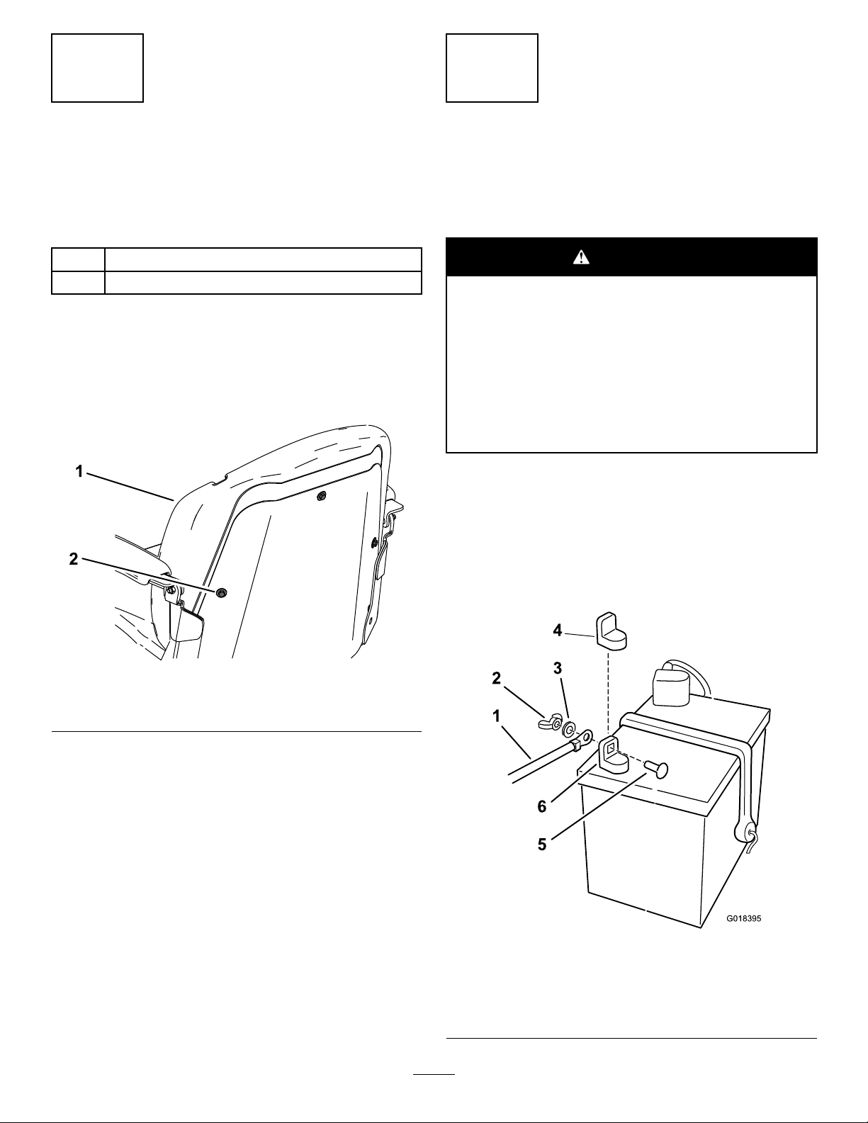
2.Installthebackcushionusingthe3anged-hex
bolts(Figure1).
ConnectingtheBattery
NoPartsRequired
Procedure
WARNING
CALIFORNIA
Proposition65Warning
Batteryposts,terminals,andrelated
accessoriescontainleadandlead
compounds,chemicalsknownto
theStateofCaliforniatocause
cancerandreproductiveharm.Wash
handsafterhandling.
1.Locatethebatteryandnegativebatterycable.
2.Removetheplasticcapfromthenegative
batterypost.
3.Removethefastenersonthenegativebattery
cable,andusethemtosecurethenegative
batterycabletothenegativebatterypost(Figure
2).
g211 172
Figure1
1.Backcushion
2.Flanged-hexbolt(3)
g018395
Figure2
1.Negativebatterycable4.Negativebatterypostcap
2.Wingnut
3.Washer6.Negativebatterypost
2
5.Carriagebolt
Page 3

3
g015397
1
2
4
InstallingtheRearHitch
Partsneededforthisprocedure:
1Rearhitch
2
Bolt(5/16x1inch)
2
Locknut(5/16inch)
Procedure
InstallthebrackettotheframeasshowninFigure
3andFigure4.
Figure3
Beforeassembly
1.Bolts2.Locknuts
SettingUpthe
Motion-ControlLevers
NoPartsRequired
Procedure
1.Locatethemotion-controlleversattached,but
foldeddownonthemachine.
2.Removetheupperbolt(3/8x1inch)and
washer;loosenthelowerbolt(3/8x1inch).
3.Raisethemotioncontrolleverstotheupright
position.
4.Aligntheholesinthemotion-controlleverwith
theholesinthecontrol-armshaft,andinstallthe
boltandwasherremovedpreviously.Repeat
thisforbothcontrollevers.
Note:Handtightenallfasteners.
5.Movethemotion-controlleverstothepark
position,raisetheseat,andmovethecontrol
leversbacktothecenterposition(neutral).
g015397
6.Verifythatthemotion-controlleversareproperly
aligned.
Note:Adjustasnecessary.Tightenall
fasteners.
Afterassembly
Figure4
5
CheckingtheMower
Adjustment
g015398
NoPartsRequired
Procedure
Adjusttheside-to-sidelevelandthefront-to-rearblade
slope.UsetherelevantproceduresintheOperator's
Manualtoverifythatthedeckislevel,andmakeany
adjustmentsasnecessary .RefertotheOperator's
Manualformoreinformation.
3
Page 4

6
CompletingtheSetup
Partsneededforthisprocedure:
1Ignitionkey
1
Hosecoupling(notincludedwithCEmodels)
1
Operator'sManual
1
Engineowner’smanual(non-T oroengines)
1
Operatortrainingmaterial
CheckingtheTirePressure
Removethepackingrestraintholdingtheside
dischargechuteupandlowerthechuteintoplace.
CheckingtheSide-Discharge
Chute
Removethepackingrestraintholdingtheside
dischargechuteupandlowerthechuteintoplace.
CheckingtheEngine-OilLevel
Beforeyoustarttheengineandusethemachine,
checktheoillevelintheenginecrankcase;referto
CheckingtheOilLevelintheOperator'sManual.
OrganizingtheMaterial
Keepallthefollowingitemswiththemachine:
•Ignitionkey
•Hosecoupling(notincludedinCEmodels)
•Operator'sManual
•Engineowners’smanual(non-Toroengines)
•Viewtheoperatortrainingmaterialbefore
operatingthemachine.
4
 Loading...