

Page 1
FormNo.3371-676RevB
50inRecycler
®
Kit
TimeCutter
®
MXSeriesRidingMower
ModelNo.79024
InstallationInstructions
Installation
LooseParts
Usethechartbelowtoverifythatallpartshavebeenshipped.
Description
Qty.
Use
Right-handbafeassembly
1
Left-handbafeassembly
1
Flangedkicker3
Recyclerbracket1
Self-tappingscrew
8
Flangenut(5/16inch)
6
Carriagebolt(5/16x3/4inch)
1
Decal1
Mulchingblade3
InstalltheRecycler®Kit.
Nopartsrequired
–
Convertthemowerdeckbacktoside-discharging.
InstallingtheRecycler®Kit
1.Stoptheengineandremovetheignitionkey.
2.Removethemowerdeckasdescribedinyour
Operator'sManual.
3.Turnthemowerdeckupsidedown.
4.Removetheexistingmowerbladesinstalledonyour
mowerdeck.
Note:RefertotheRemovingtheBladessectionin
theOperator’sManualformoreinformation.
5.Removeanydebrisandgrassclippingsfromthe
undersideofthemowerdeck.
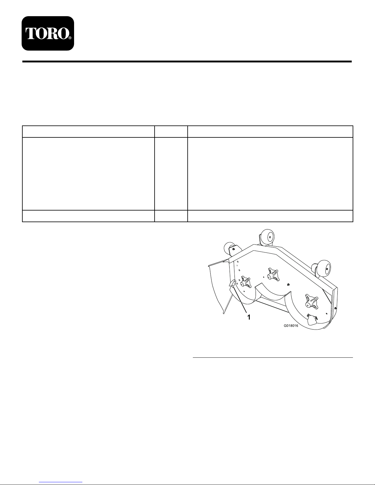
6.Locatethecutoffbafeatthesidedischargeopening
onthemowerdeck(
Figure1).
G018016
1
Figure1
1.Cutoffbafe(existing)
7.Removethefastenersthatsecurethecutoffbafeto
themowerdeckandremovethecutoffbafe.
Note:Savethecutoffbafeforconvertingbackto
sidedischarge.
8.Installthefastenersintothesameholesinthemower
deckfromwhichtheywereoriginallyremoved.
Note:Thisensuresthatnoholesareleftopenwhen
youoperatethemowerdeck.
©2012—TheToro®Company
8111LyndaleAvenueSouth
Bloomington,MN55420
Registeratwww.Toro.com.
OriginalInstructions(EN)
PrintedintheUSA
AllRightsReserved
Page 2
DANGER
Openholesinthemowerdeckexposeyouand
otherstothrowndebris.Debristhrownoutof
theholesinthemowerdeckcancauseinjury.
•Neveroperatethemowerdeckwithout
hardwaremountedinallholesinthemower
deck.
•Installhardwareinthemountingholeswhen
youremovethebafe.
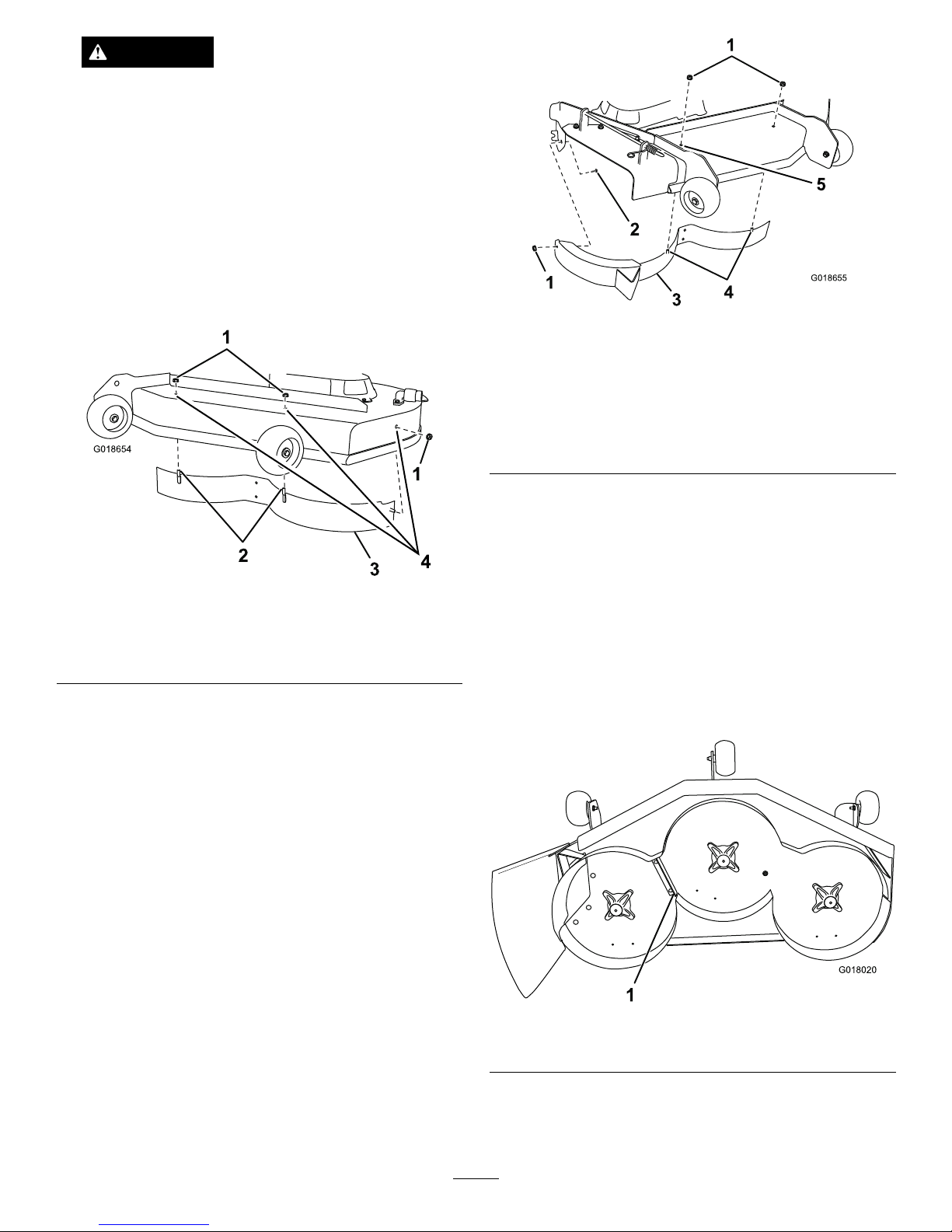
9.Removetheplugboltsandnutsatthelocations
showninFigure2.
G018654
1
2
3
1
4
Figure2
1.Locknut(5/16inch)3.Leftbafe
2.Carriagebolt(5/16x3/4
inch)
4.Removetheplugboltsand
nutshere.
10.Installtheleft-handbafetothemowerdeckusing3
locknuts(5/16inch)tosecuretheweldedpostsof
theleft-handbafetothetopofthemowerdeckat
thepositionsshownin
Figure2.
Note:Handtightenthefasteners.
11.Tightenallfastenerssecurely.
12.Installtheright-handbafetothemowerdeckas
shownin
Figure3.
Note:Removetheplugboltandnutshownin
Figure3beforeinstallingthebafe.
G018655
1
2
3
4
1
5
Figure3
Thedeectorhasbeenremovedforthepurposeofclarity.
1.Flangenut(5/16inch)
4.Weldedposts
2.Carriagebolt(5/16x3/4
inch)
5.Removetheplugandbolt
herebeforeinstallingthe
bafe.
3.Right-handbafe
Note:Use2locknuts(5/16inch)tosecurethe
weldedpostsoftherightbafetothetopofthe
mowerdeckatcenterandrightofcenterpositions.
Handtightenthefasteners.
13.Installacarriagebolt(5/16x3/4inch)andalocknut
(5/16inch)throughrearwallofthemowerdeck
andtheright-handbafetosecurethebafetothe
mowerdeck(
Figure3).
14.Tightenallfasteners.
15.InstalltheRecyclerbracketwith2self-tappingscrews
(5/16x3/4inch)atthelocationshowninFigure4.
G018020
1
Figure4
1.Recyclerbracket
16.Installthekickerstotheundersideofthemower
deckwith6self-tappingscrews(5/16x3/4inch)at
thelocationsshowninFigure5.
2
Page 3

G018019
1
2
Figure5
1.Flangescrews(5/16x3/4
inch)
2.Kickers
17.InstallthedecaltotheareashowninFigure6.
G018015
1
Figure6
1.Decal
A.Thoroughlycleantheareawhereyouwillinstall
thedecal.
B.Dampentheareawithwaterormildlysoapy
water.
C.Peelthedecalfromthebackingandinstallitin
place(Figure6).
D.Squeegeeacrossthesurfaceofthedecal,starting
atthecenterofthedecalandworkingtowardthe
edges,usingoverlappingstrokes.
18.Installthemulchingmowerbladeslocatedinloose
parts.
Note:RefertotheInstallingtheBladessectionin
theOperator’sManualformoreinformation.
ConvertingtheMowerDeck
BacktoSide-discharging
ReversethestepsintheprocedureInstallingtheRecycler
Kitabove.
3
Page 4

Operation
OperatingTips
SelectingtheProperHeight-of-Cut
SettingtoSuittheConditions
Removeapproximatelyoneinchornomorethat1/3
ofthegrassbladewhencutting.Inexceptionallylush
anddensegrassyoumayneedtoraisetheheight-of-cut
settinganothernotchorconverttoside-dischargingor
baggingoperations.
LongGrass
Ifthegrasshasgrownslightlylongerthannormal,orif
itcontainsahighdegreeofmoisture,raisethecutting
heighthigherthanusualandcutthegrassatthissetting.
Thencutthegrassagainusingthelower,normalsetting.
MowinginExtremeConditions
Airisrequiredtocutandrecutgrassclippingsinthe
mowerdeck,sodonotsettheheight-of-cuttoolowor
totallysurroundthehousingbyuncutgrass.Always
haveonesideofthemowerdeckfreefromuncut
grass,allowingairtobedrawnintothehousing.When
makinganinitialcutthroughthecenteroftheuncut
area,operatethemachineataslowerspeedandbackup
ifthemowerdeckstartstoclog.
MowingattheProperIntervals
Undernormalconditionsyou'llneedtomowevery4
to5days.However,grassgrowsatdifferentratesat
differenttimes.Thus,inordertomaintainthesame
height-of-cut,whichisagoodpractice,you'llneedto
cutmorefrequentlyinearlyspring;asthegrassgrowth
rateslowsinmidsummer,cutonlyevery8to10days.
Ifyouareunabletomowforanextendedperioddue
totheweatherconditionsorotherreasons,convertto
side-dischargingorbaggingoptionsormowrstwith
theheight-of-cutatahighlevel;thenmowagain2to3
dayslateratalowerheightsetting.
AlwaysMowwithSharpBlades
Asharpbladecutscleanlyandwithouttearingor
shreddingthegrassbladelikeadullblade.Tearingand
shreddingcausesthegrasstoturnbrownattheedges,
whichimpairsgrowthandincreasessusceptibilityto
disease.
CleaningAfterOperating
Toensureoptimumperformance,cleantheunderside
ofthemowerdeck.Ifresidueisallowedtobuildupin
mowerdeck,cuttingperformancewilldecrease.
4
 Loading...