

Page 1
FormNo.3410-275RevB
TimeCutter
®
HDXS4850and
X5450RidingMower
ModelNo.74866—SerialNo.400000000andUp
ModelNo.74867—SerialNo.400000000andUp
Registeratwww.T oro.com.
OriginalInstructions(EN)
*3410-275*B
Page 2
WARNING
CALIFORNIA
Proposition65Warning
Thisproductcontainsachemicalorchemicals
knowntotheStateofCaliforniatocausecancer,
birthdefects,orreproductiveharm.
Theengineexhaustfromthisproduct
containschemicalsknowntotheStateof
Californiatocausecancer,birthdefects,
orotherreproductiveharm.
ThisproductcomplieswithallrelevantEuropeandirectives;
fordetails,pleaseseetheseparateproductspecicDeclaration
ofConformity(DOC)sheet.
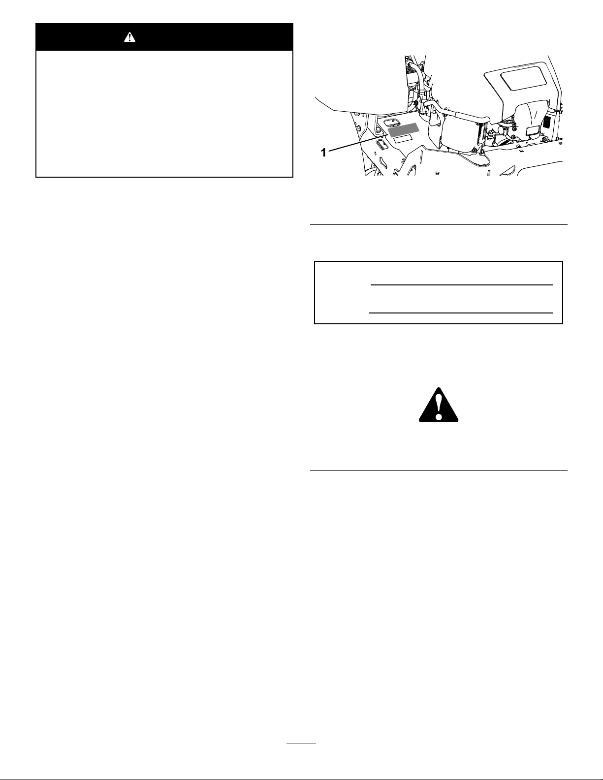
modelandserialnumbersontheproduct.Writethenumbers
inthespaceprovided.
g188704
Figure1
1.Modelandserialnumberplate
ItisaviolationofCaliforniaPublicResourceCode
Section4442or4443touseoroperatetheengineonany
forest-covered,brush-covered,orgrass-coveredlandunless
theengineisequippedwithasparkarrester,asdenedin
Section4442,maintainedineffectiveworkingorderorthe
engineisconstructed,equipped,andmaintainedforthe
preventionofre.
GrossHorsepower
Thegrossornethorsepowerofthisenginewaslaboratory
ratedbytheenginemanufacturerinaccordancewiththe
SocietyofAutomotiveEngineers(SAE)J1940.Ascongured
tomeetsafety,emission,andoperatingrequirements,
theactualenginetorqueonthisclassofmowerwillbe
signicantlylower.
Gotowww .Toro.comtoviewspecicationsonyourmower
model.
Introduction
Thisrotary-blade,ridinglawnmowerisintendedtobeused
byresidentialhomeownersorhiredoperators.Itisdesigned
primarilyforcuttinggrassonwell-maintainedlawnson
residentialorcommercialproperties.Itisnotdesignedfor
cuttingbrushorforagriculturaluses.
Writetheproductmodelandserialnumbersinthespace
below:
ModelNo.
SerialNo.
Thismanualidentiespotentialhazardsandhassafety
messagesidentiedbythesafety-alertsymbol(Figure2),
whichsignalsahazardthatmaycauseseriousinjuryordeath
ifyoudonotfollowtherecommendedprecautions.
g000502
Figure2
1.Safety-alertsymbol.
Thismanualuses2wordstohighlightinformation.
Importantcallsattentiontospecialmechanicalinformation
andNoteemphasizesgeneralinformationworthyofspecial
attention.
Contents
Readthisinformationcarefullytolearnhowtooperateand
maintainyourproductproperlyandtoavoidinjuryand
productdamage.Youareresponsibleforoperatingthe
productproperlyandsafely.
YoumaycontactTorodirectlyatwww .Toro.comforproduct
safetyandoperationtrainingmaterials,accessoryinformation,
helpndingadealer,ortoregisteryourproduct.
Wheneveryouneedservice,genuineT oroparts,oradditional
information,contactanAuthorizedServiceDealerorToro
CustomerServiceandhavethemodelandserialnumbersof
yourproductready.Figure1identiesthelocationofthe
©2017—TheToro®Company
8111LyndaleAvenueSouth
Bloomington,MN55420
Safety...........................................................................4
GeneralSafety.........................................................4
SlopeIndicator.......................................................5
SafetyandInstructionalDecals.................................6
ProductOverview.........................................................11
Controls...............................................................11
BeforeOperation......................................................13
BeforeOperationSafety..........................................13
RecommendedFuel................................................13
UsingStabilizer/Conditioner...................................13
FillingtheFuelTank...............................................14
CheckingtheEngine-OilLevel.................................14
Contactusatwww.Toro.com.
2
PrintedintheUSA
AllRightsReserved
Page 3

BreakinginaNewMachine......................................14
ThinkSafetyFirst...................................................14
UsingtheSafety-InterlockSystem.............................15
PositioningtheSeat................................................15
AdjustingtheMyRide™SuspensionSystem...............16
AdjustingtheMotion-ControlLevers........................17
DuringOperation.....................................................17
DuringOperationSafety.........................................17
OperatingtheParkingBrake....................................18
OperatingtheMowerBlade-ControlSwitch
(PTO)...............................................................19
OperatingtheThrottle............................................19
OperatingtheChoke...............................................19
OperatingtheIgnitionSwitch..................................20
StartingandShuttingOfftheEngine.........................20
UsingtheMotion-ControlLevers.............................21
DrivingtheMachine...............................................21
UsingtheSmartSpeed
TM
ControlSystem..................22
StoppingtheMachine.............................................22
UsingtheSideDischarge.........................................23
AdjustingtheHeightofCut.....................................23
AdjustingtheAnti-ScalpRollers...............................24
Convertingthe48-inchMowerDecktoSide
Discharge..........................................................24
Convertingthe54-inchMowerDecktoSide
Discharge..........................................................26
UsingAttachmentsandAccessories..........................28
OperatingTips......................................................28
AfterOperation........................................................29
AfterOperationSafety............................................29
PushingtheMachinebyHand..................................30
TransportingtheMachine........................................30
LoadingtheMachine..............................................31
Maintenance.................................................................32
RecommendedMaintenanceSchedule(s)......................32
Pre-MaintenanceProcedures......................................33
MaintenanceandStorageSafety................................33
ReleasingtheMower-DeckCurtain...........................33
EngineMaintenance..................................................34
EngineSafety.........................................................34
ServicingtheAirCleaner.........................................34
ServicingtheEngineOil..........................................35
ServicingtheSparkPlug..........................................37
CleaningtheCoolingSystem....................................38
FuelSystemMaintenance...........................................39
ReplacingtheIn-LineFuelFilter...............................39
ElectricalSystemMaintenance....................................40
ElectricalSystemSafety...........................................40
ServicingtheBattery...............................................40
ServicingtheFuses.................................................42
DriveSystemMaintenance.........................................42
CheckingtheTirePressure......................................42
MowerMaintenance...................................................43
ServicingtheCuttingBlades.....................................43
LevelingtheMowerDeck........................................45
RemovingtheMowerDeck.....................................47
InstallingtheMowerDeck.......................................48
ReplacingtheGrassDeector..................................48
MowerBeltMaintenance............................................49
InspectingtheBelts................................................49
ReplacingtheMowerBelt........................................49
Cleaning...................................................................50
WashingtheUndersideoftheMower........................50
CleaningtheSuspensionSystem...............................51
DisposingofWaste.................................................51
Storage........................................................................51
CleaningandStorage..............................................51
Troubleshooting...........................................................53
Schematics...................................................................55
3
Page 4

Safety
ThismachinehasbeendesignedinaccordancewithENISO
5395:2013.
GeneralSafety
Thisproductiscapableofamputatinghandsandfeetand
ofthrowingobjects.Alwaysfollowallsafetyinstructionsto
avoidseriouspersonalinjury.
Usingthisproductforpurposesotherthanitsintendeduse
couldprovedangeroustoyouandbystanders.
•ReadandunderstandthecontentsofthisOperator’ sManual
beforeyoustarttheengine.Ensurethateveryoneusing
thisproductknowshowtouseitandunderstandsthe
warnings.
•Donotputyourhandsorfeetnearmovingcomponents
ofthemachine.
•Donotoperatethemachinewithoutallguardsandother
safetyprotectivedevicesinplaceandworkingonthe
machine.
•Keepclearofanydischargeopening.Keepbystandersa
safedistanceawayfromthemachine.
•Keepchildrenoutoftheoperatingarea.Neverallow
childrentooperatethemachine.
•Stopthemachineandshutofftheenginebeforeservicing,
fueling,oruncloggingthemachine.
Improperlyusingormaintainingthismachinecanresult
ininjury.Toreducethepotentialforinjury,complywith
thesesafetyinstructionsandalwayspayattentiontothe
safety-alertsymbol,whichmeansCaution,Warning,or
Danger—personalsafetyinstruction.Failuretocomplywith
theseinstructionsmayresultinpersonalinjuryordeath.
Youcanndadditionalitemsofsafetyinformationintheir
respectivesectionsthroughoutthismanual.
4
Page 5
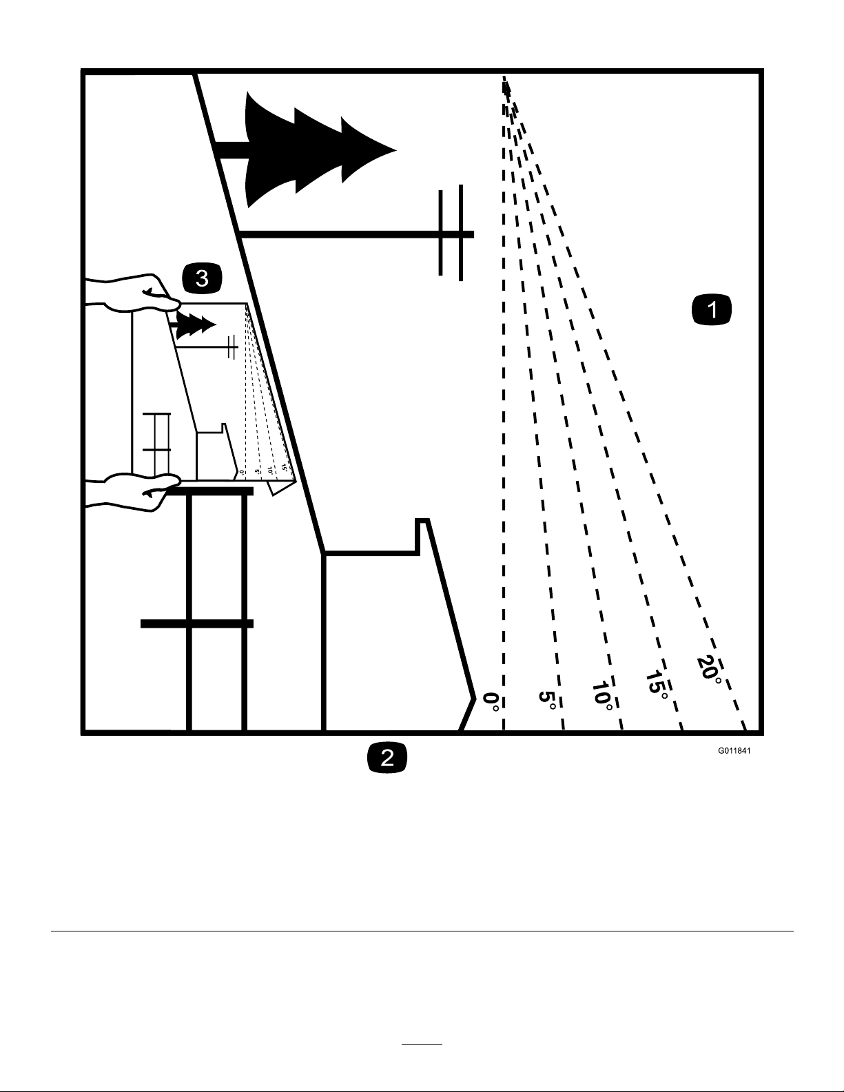
SlopeIndicator
G011841
Figure3
Thispagemaybecopiedforpersonaluse.
1.Themaximumslopeyoucansafelyoperatethemachineonis15degrees.Usetheslopecharttodeterminethedegreeofslope
ofhillsbeforeoperating.Donotoperatethismachineonaslopegreaterthan15degrees.Foldalongtheappropriateline
tomatchtherecommendedslope.
2.Alignthisedgewithaverticalsurface,atree,building,fencepole,etc.
3.Exampleofhowtocompareslopewithfoldededge
5
g011841
Page 6
SafetyandInstructionalDecals
Safetydecalsandinstructionsareeasilyvisibletotheoperatorandarelocatednearanyareaofpotential
danger.Replaceanydecalthatisdamagedormissing.
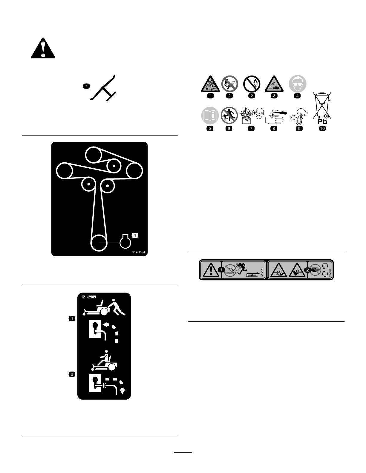
Manufacturer'sMark
1.Indicatesthebladeisidentiedasapartfromtheoriginal
machinemanufacturer.
decaloemmarkt
decalbatterysymbols
BatterySymbols
Someorallofthesesymbolsareonyourbattery .
1.Explosionhazard
6.Keepbystandersasafe
distanceawayfromthe
battery.
2.Nore,opename,or
smoking
7.Weareyeprotection;
explosivegasescan
causeblindnessandother
injuries.
3.Causticliquid/chemical
burnhazard
8.Batteryacidcancause
blindnessorsevereburns.
4.Weareyeprotection.9.Flusheyesimmediately
withwaterandgetmedical
helpfast.
5.ReadtheOperator's
Manual.
decal117-1194
10.Containslead;donot
discard.
117-1194
1.Engine
decal130-0731
130-0731
1.Warning—thrownobject
hazard;keepthedeector
shieldinplace.
2.Cuttinghazardofhandor
foot,mowerblade—keep
awayfrommovingparts.
1.Bypassleverpositionfor
pushingthemachine
decal121-2989b
121-2989
2.Bypassleverpositionfor
operatingthemachine
6
Page 7
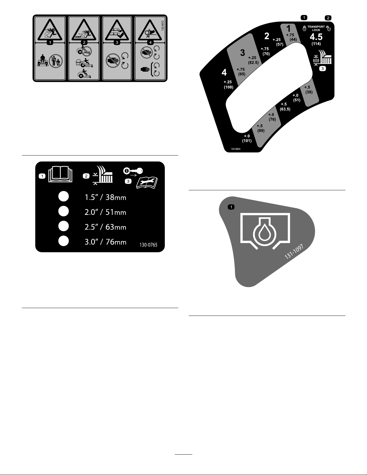
decal132-0872
132-0872
1.Thrownobject
hazard—keepbystanders
awayfromthemachine.
2.Thrownobjecthazard,
raisedbafe—donot
operatethemachinewith
anopendeck;usea
baggerorabafe.
1.ReadtheOperator's
Manual.
2.Height-of-cutselection
3.Severinghazardofhand
4.Entanglement
130-0765
3.Removethekeyfrom
orfoot—keepawayfrom
movingparts.
hazard—keepaway
frommovingparts;keep
allguardsandshieldsin
place.
theignitionandreadthe
Operator'sManualbefore
performingmaintenance.
decal130-0654
130-0654
1.Transport—lock
2.Transport—unlock
decal130-0765
3.Heightofcut
decal131-1097
131-1097
1.Oildrain
7
Page 8
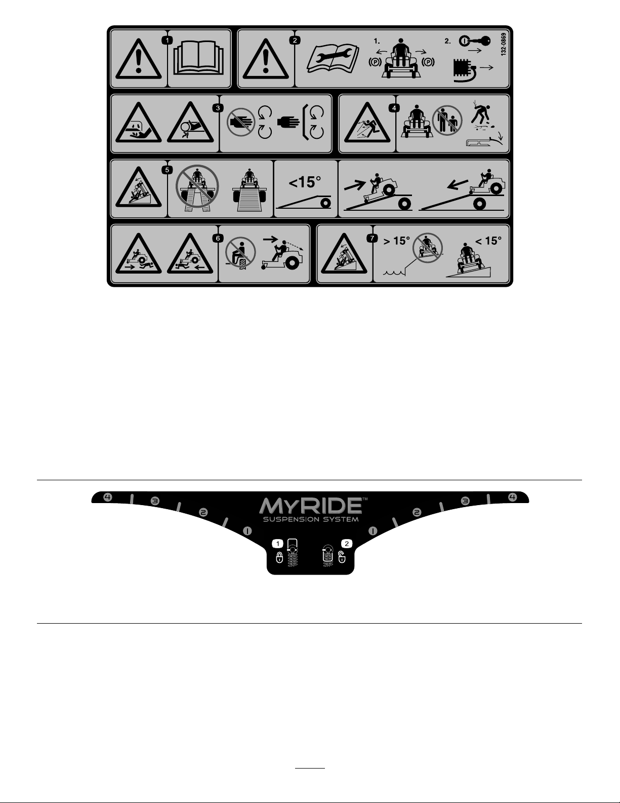
decal132-0869
132-0869
1.Warning—readtheOperator'sManual.
2.Warning—readtheinstructionsbeforeservicingorperforming
5.Ramphazard—Whenloadingontoatrailer,donotusesplit
6.Crushing/dismembermenthazardofbystanders,inreverse
maintenance;movethemotion-controlleverstothepark
(brake)position,removetheignitionkey,anddisconnectthe
spark-plugwire.
3.Cutting/dismembermenthazard,mowerblade;entanglement
7.Tippinghazard—donotusethemachineneardrop-offswith
hazard,belt—stayawayfrommovingpartsandkeepall
guardsandshieldsinplace.
4.Thrownobjecthazard—keepbystandersasafedistance
awayfromthemachine,pickupdebrisbeforeoperating,and
keepthedeectorinplace.
133-5198
1.Camlock2.Camunlock
ramps.Onlyuseafull-widthrampwideenoughforthe
machine.Rampanglewiththegroundshouldbelessthan15
degrees.Backuptherampanddriveforwardofftheramp.
andforward—donotcarrypassengers,lookbehindanddown
whenreversing.
slopesgreaterthan15degreesornearwater;onlyuseon
slopeslessthan15degrees.
decal133-5198
8
Page 9
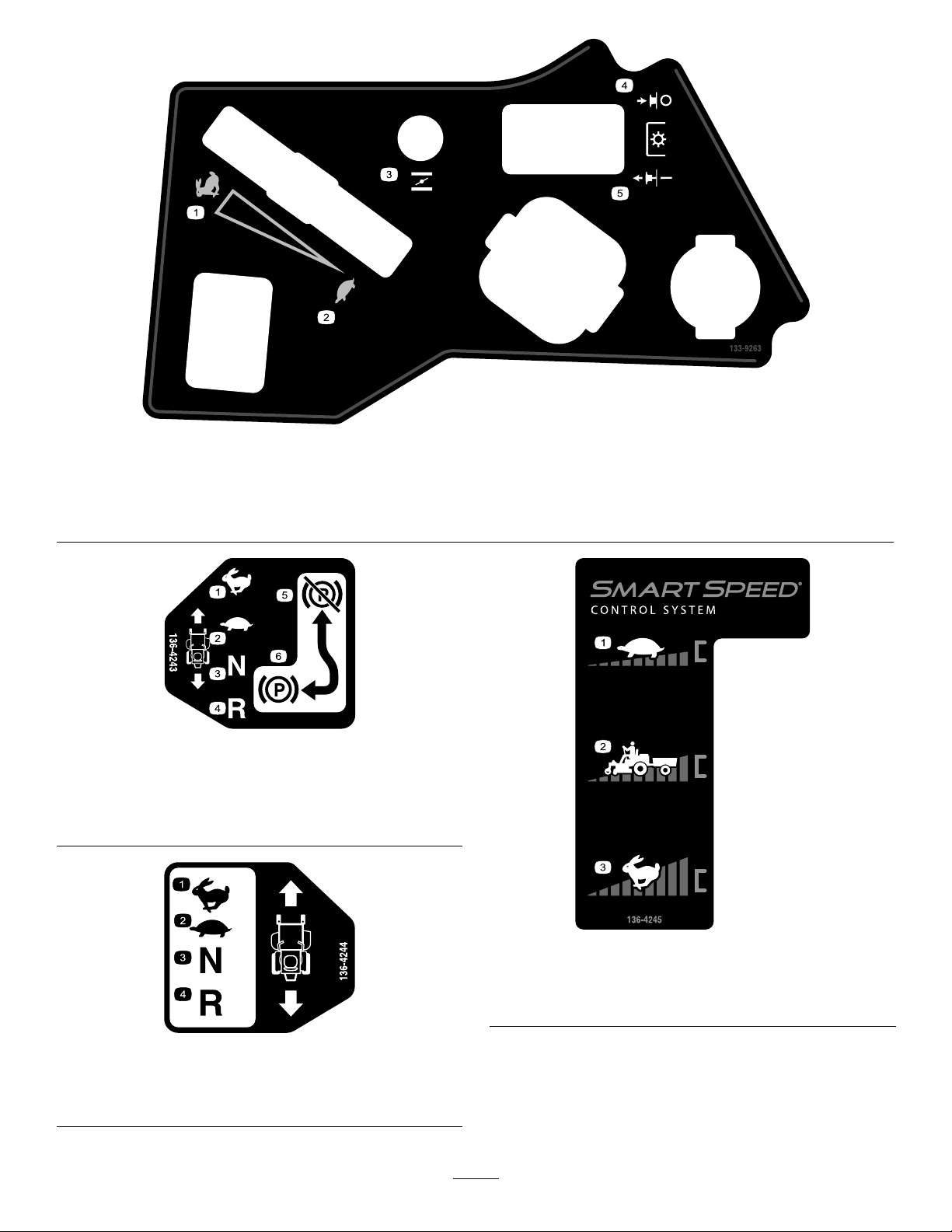
decal133-9263
133-9263
1.Fast
2.Slow5.PTOengage
3.Choke
decal136-4243
136-4243
1.Fast4.Reverse
2.Slow
3.Neutral6.Parkingbrakeengaged
5.Parkingbrakedisengaged
4.PTOdisengage
136-4244
1.Fast3.Neutral
2.Slow
decal136-4245
136-4245
1.Slow
2.Transport
decal136-4244
4.Reverse
3.Fast
9
Page 10
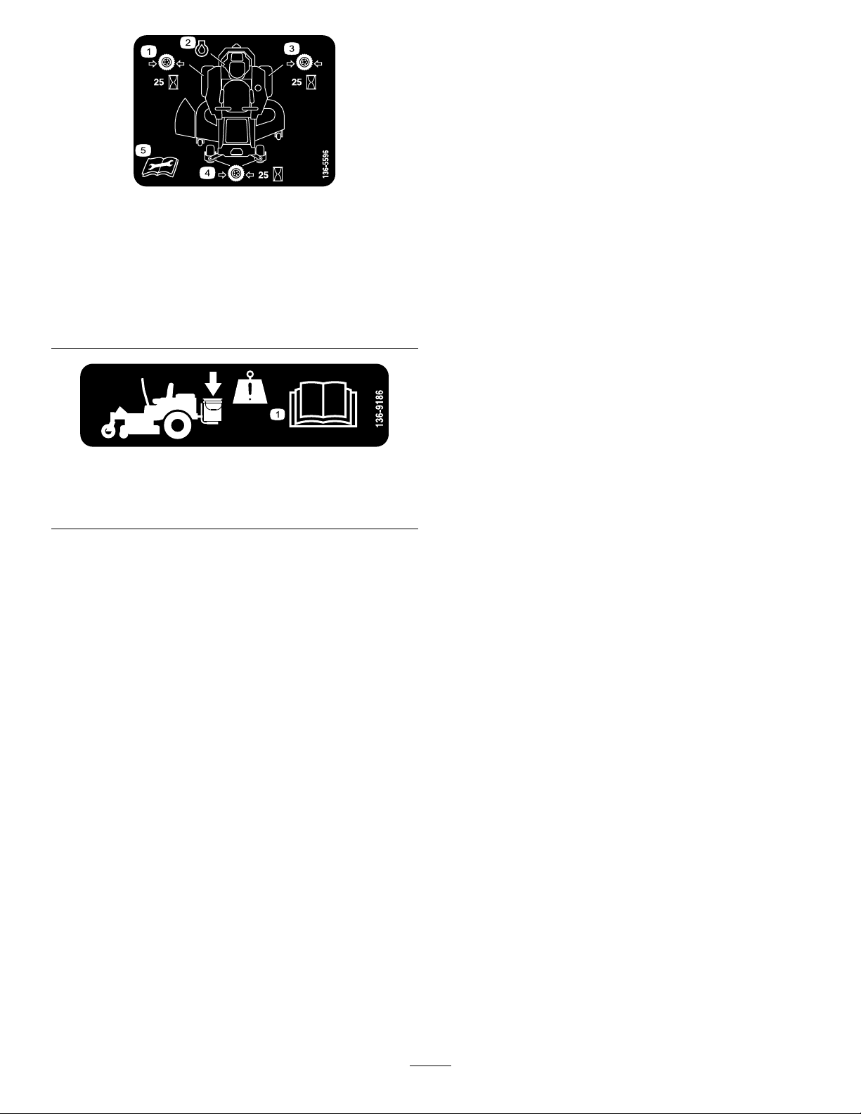
decal136-5596
136-5596
1.Checkthetirepressure
every25operatinghours.
2.Engineoil
4.Checkthetirepressure
every25operatinghours.
5.ReadtheOperator's
Manualbeforeperforming
maintenance.
3.Checkthetirepressure
every25operatinghours.
136-9186
1.ReadtheOperator'sManualbeforeaddingweighttothe
bucket.
decal136-9186
10
Page 11
ProductOverview
Controls
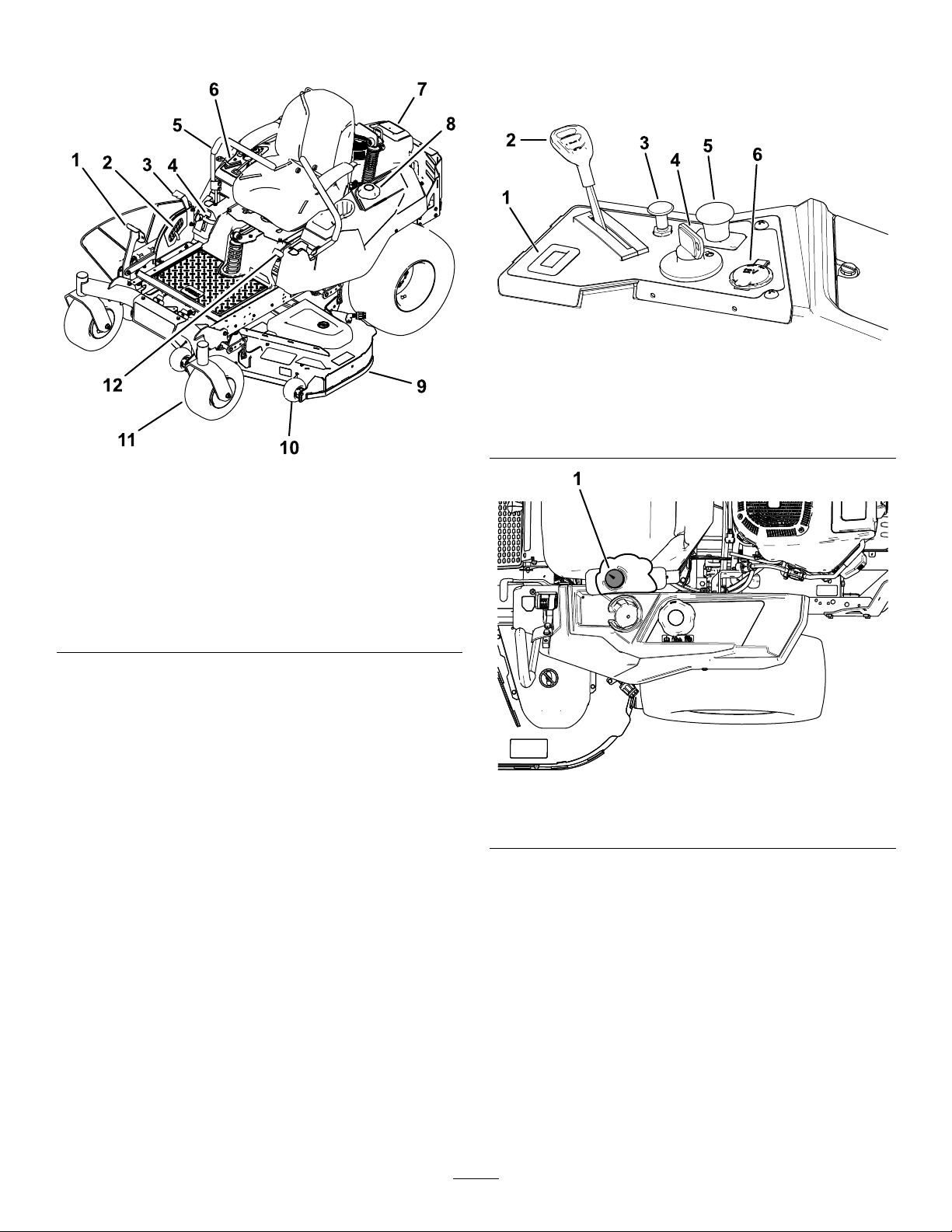
BecomefamiliarwithallcontrolsinFigure5andFigure6
beforeyoustarttheengineandoperatethemachine.
g188738
Figure5
1.Hourmeter4.Ignitionswitch
2.Throttlecontrol
3.Chokecontrol
g195717
Figure4
5.PTOswitch
6.12Vpowerpoint
1.Deck-liftpedal
2.Height-of-cutpin
3.Height-of-cut
lever/transportlock
4.SmartSpeed™lever
5.Motion-controllever
6.Controls
7.Engine
8.Fuelcap
9.Mowerdeck
10.Anti-scalproller
11.Casterwheel
12.Parking-brakelever
g188776
Figure6
1.Fuelgauge
FuelGauge
Thefuelgaugedisplaystheamountoffuelinthetank(Figure
6).
ThrottleControl
Thethrottlecontrolstheenginespeed,andithasa
continuous-variablesettingfromtheSLOWtoFASTposition
(Figure5).
11
Page 12

ChokeControl
Blade-ControlSwitch(PowerTakeoff)
Usethechokecontroltostartacoldengine.Pullthechoke
controluptoengageit.Pushdownonthechokecontrolto
disengageit.
HourMeter
Thehourmeterrecordsthenumberofhourstheenginehas
operated.Itoperateswhentheengineisrunning.Usethese
timesforschedulingregularmaintenance(Figure5).
Motion-ControlLevers
Themotion-controlleversarespeed-sensitivecontrolsof
independentwheelmotors.Movingaleverforwardor
backwardturnsthewheelonthesamesideforwardor
inreverse;wheelspeedisproportionaltotheamountthe
leverismoved.Movethecontrolleversoutwardfromthe
centertotheNEUTRAL-LOCKpositionandexitthemachine
(Figure4).Alwayspositionthemotion-controlleversinto
theNEUTRAL-LOCKpositionwhenyoustopthemachine
orleaveitunattended.
Parking-BrakeLever
Theblade-controlswitch(PTO)engagesanddisengages
powertothemowerblades(Figure5).
Height-of-CutLever
Theheight-of-cutleverworkswiththefootpedaltolockthe
deckinaspeciccuttingheight.Onlyadjusttheheightofcut
whilemachineisnotmoving(Figure4).
Attachments/Accessories
AselectionofToroapprovedattachmentsandaccessoriesis
availableforusewiththemachinetoenhanceandexpand
itscapabilities.ContactyourAuthorizedServiceDealeror
Distributororgotowww .Toro.comforalistofallapproved
attachmentsandaccessories.
Theparking-brakeleverislocatedonleftsideoftheconsole
(Figure4).Thebrakeleverengagesaparkingbrakeonthe
drivewheels.
Toengagetheparkingbrake,pulluptheleveruntilitlatches
intothedetentslot.
Todisengagetheparkingbrake,pulltheleveroutofthe
detentslotandtowardyou,thenpushitdown.
FootPedalDeck-LiftSystem
Thefootpedaldeck-liftsystemallowsyoutolowerandraise
thedeckfromtheseatedposition.Youcanusethefootpedal
toliftthedeckbrieytoavoidobstaclesorlockthedeckin
thehighestheightofcutortransportposition(Figure4).
SmartSpeed™ControlSystemLever
TheSmartSpeed™Control-Systemlever,locatedbelowthe
operatingposition,givesyouachoicetodrivethemachineat
3speedranges—trim,tow ,andmow(Figure26).
12VPowerPoint
Usethepowerpointtopower12Vaccessories(Figure5).
Important:Whennotusingthe12Vpowerpoint,insert
therubberplugtopreventdamagetothepowerpoint.
IgnitionSwitch
Usethisswitchtostartthemowerengine.Ithas3positions:
START,RUN,andOFF.
12
Page 13

Operation
Note:Determinetheleftandrightsidesofthemachine
fromthenormaloperatingposition.
BeforeOperation
BeforeOperationSafety
GeneralSafety
•Neverallowchildrenoruntrainedpeopletooperateor
servicethemachine.Localregulationsmayrestrictthe
ageoftheoperator.Theownerisresponsiblefortraining
alloperatorsandmechanics.
•Becomefamiliarwiththesafeoperationoftheequipment,
operatorcontrols,andsafetysigns.
•Knowhowtostopthemachineandshutofftheengine
quickly.
•Checkthatoperator-presencecontrols,safetyswitches,
andshieldsareattachedandfunctioningproperly.Donot
operatethemachineunlesstheyarefunctioningproperly.
•Beforemowing,alwaysinspectthemachinetoensurethat
theblades,bladebolts,andcuttingassembliesareingood
workingcondition.Replacewornordamagedbladesand
boltsinsetstopreservebalance.
•Inspecttheareawhereyouwillusethemachineand
removeallobjectsthatthemachinecouldthrow.
•Evaluatetheterraintodeterminetheappropriate
equipmentandanyattachmentsoraccessoriesrequiredto
operatethemachineproperlyandsafely.
FuelSafety
•Toavoidpersonalinjuryorpropertydamage,useextreme
careinhandlingfuel.Fuelvaporsareammableand
explosive.
•Extinguishallcigarettes,cigars,pipes,andothersources
ofignition.
•Useonlyanapprovedfuelcontainer.
•Donotremovethefuelcaporaddfueltothefueltank
whiletheengineisrunningorwhilehot.
•Donotrefuelthemachineindoors.
•Donotstorethemachineorfuelcontainerwherethere
isanopename,spark,orpilotlight,suchasonawater
heateroronotherappliances.
•Donotllcontainersinsideavehicleoronatruckor
trailerbedwithaplasticliner.Alwaysplacecontainerson
theground,awayfromyourvehiclebeforelling.
•Removetheequipmentfromthetruckortrailerand
refuelitwhileitisontheground.Ifthisisnotpossible,
thenrefuelfromaportablecontainerratherthana
fuel-dispensernozzle.
•Donotoperatethemachinewithouttheentireexhaust
systeminplaceandinproperworkingcondition.
•Keepthefuel-dispensernozzleincontactwiththerimof
thefueltankorcontaineropeningatalltimesuntilfueling
iscomplete.Donotuseanozzlelock-opendevice.
•Ifyouspillfuelonyourclothing,changeyourclothing
immediately.Wipeupanyfuelthatspills.
•Neveroverllthefueltank.Replacethefuelcapand
tightenitsecurely.
•Storefuelinanapprovedcontainerandkeepitoutofthe
reachofchildren.Neverbuymorethana30-daysupply
offuel.
•Donotllthefueltankcompletelyfull.Addfueltothe
fueltankuntilthelevelis6to13mm(1/4to1/2inch)
belowthebottomofthellerneck.Thisemptyspacein
thetankallowsfueltoexpand.
–Avoidprolongedbreathingofvapors.
–Keepyourfaceawayfromthenozzleandfueltank
opening.
–Avoidcontactwithskin;washoffspillswithsoapand
water.
RecommendedFuel
•Forbestresults,useonlyclean,fresh(lessthan30days
old),unleadedgasolinewithanoctaneratingof87or
higher((R+M)/2ratingmethod).
•Ethanol:Gasolinewithupto10%ethanol(gasohol)
or15%MTBE(methyltertiarybutylether)byvolume
isacceptable.EthanolandMTBEarenotthesame.
Gasolinewith15%ethanol(E15)byvolumeisnot
approvedforuse.Neverusegasolinethatcontains
morethan10%ethanolbyvolume,suchasE15
(contains15%ethanol),E20(contains20%ethanol),or
E85(containsupto85%ethanol).Usingunapproved
gasolinemaycauseperformanceproblemsand/orengine
damagewhichmaynotbecoveredunderwarranty.
•Donotusegasolinecontainingmethanol.
•Donotstorefueleitherinthefueltankorfuelcontainers
overthewinterunlessyouuseafuelstabilizer.
•Donotaddoiltogasoline.
UsingStabilizer/Conditioner
Useafuelstabilizer/conditionerinthemachinetoprovide
thefollowingbenets:
•Keepsfuelfreshduringstorageof90daysorless(drain
thefueltankwhenstoringthemachineformorethan
90days)
•Cleanstheenginewhileitruns
•Eliminatesgum-likevarnishbuildupinthefuelsystem,
whichcauseshardstarting
Important:Donotusefueladditivescontaining
methanolorethanol.
13
Page 14
Addthecorrectamountoffuelstabilizer/conditioner
tothefuel.
Note:Afuelstabilizer/conditionerismosteffective
whenmixedwithfreshfuel.T ominimizethechanceof
varnishdepositsinthefuelsystem,usefuelstabilizerat
alltimes.
BreakinginaNewMachine
Newenginestaketimetodevelopfullpower.Mowerdecks
anddrivesystemshavehigherfrictionwhennew,placing
additionalloadontheengine.Allow40to50hoursof
break-intimefornewmachinestodevelopfullpowerand
bestperformance.
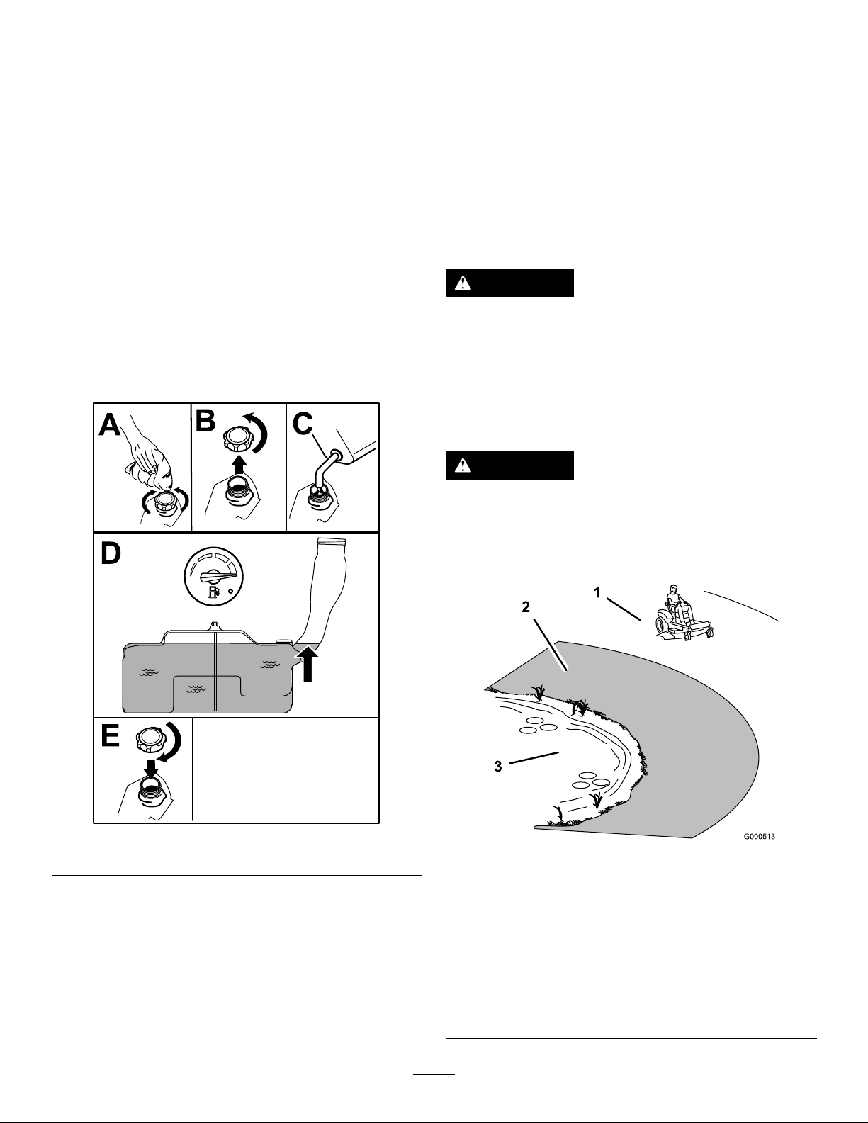
FillingtheFuelTank
1.Parkthemachineonalevelsurface.
2.Engagetheparkingbrake.
3.Shutofftheengineandremovethekey.
4.Cleanaroundthefuel-tankcap.
5.Fillthefueltankuntilthefuelgaugereadsatthefull
mark(Figure7).
Note:Donotllthefueltankcompletelyfull.The
emptyspaceinthetankallowsthefueltoexpand.
ThinkSafetyFirst
Pleasereadallsafetyinstructionsandsymbolsinthesafety
section.Knowingthisinformationcouldhelpyouor
bystandersavoidinjury.
DANGER
Operatingthemachineonwetgrassorsteepslopes
cancauseslidingandlossofcontrol.
•Donotoperateonslopesgreaterthan15degrees.
•Reducespeedanduseextremecautionon
slopes.
•Donotoperatethemachinenearwater.
DANGER
Wheelsdroppingoveredgescancauserollovers,
whichmayresultinseriousinjury,death,or
drowning.
Donotoperatethemachineneardrop-offs.
Figure7
CheckingtheEngine-OilLevel
Beforeyoustarttheengineandusethemachine,check
theoillevelintheenginecrankcase;refertoCheckingthe
Engine-OilLevel(page14).
g197123
g000513
Figure8
1.SafeZone—usethe
machinehereonslopes
lessthan15degreesor
atareas.
2.DangerZone—usea
walk-behindmowerand/or
ahandtrimmeronslopes
greaterthan15degrees
andneardrop-offsor
water.
14
3.Water
Page 15

CAUTION
G009027
1
2
Thismachineproducessoundlevelsinexcessof
85dBAattheoperator’searandcancausehearing
lossthroughextendedperiodsofexposure.
Wearhearingprotectionwhenoperatingthis
machine.
Useprotectiveequipmentforyoureyes,ears,hands,feet,
andhead.
1.Sitontheseat,engagetheparkingbrake,andmovethe
blade-controlswitch(PTO)totheONposition.Try
startingtheengine;theengineshouldnotcrank.
2.Sitontheseat,engagetheparkingbrake,andmovethe
blade-controlswitch(PTO)totheOFFposition.Move
eithermotion-controllever(outoftheNEUTRAL-LOCK
position).Trystartingtheengine;theengineshould
notcrank.Repeatforothercontrollever.
3.Sitontheseat,engagetheparkingbrake,movethe
blade-controlswitch(PTO)totheOFFposition,and
movethemotion-controlleverstotheNEUTRAL-LOCK
position.Starttheengine.Whiletheengineisrunning,
releasetheparkingbrake,engagetheblade-control
switch(PTO),andriseslightlyfromtheseat;theengine
shouldshutoff.
g009027
Figure9
1.Weareyeprotection.2.Wearhearingprotection.
UsingtheSafety-Interlock System
WARNING
Ifthesafety-interlockswitchesaredisconnectedor
damaged,themachinecouldoperateunexpectedly,
causingpersonalinjury.
•Donottamperwiththeinterlockswitches.
•Checktheoperationoftheinterlockswitches
dailyandreplaceanydamagedswitchesbefore
operatingthemachine.
UnderstandingtheSafety-Interlock
System
Thesafety-interlocksystemisdesignedtopreventtheengine
fromstartingunless:
•Theblade-controlswitch(PTO)isdisengaged.
•Themotion-controlleversareintheNEUTRAL-LOCK
position.
•Theparkingbrakeisengaged.
4.Sitontheseat,engagetheparkingbrake,movethe
blade-controlswitch(PTO)totheOFFposition,and
movethemotion-controlleverstoNEUTRAL-LOCK
position.Starttheengine.Whiletheengineisrunning,
centereithermotion-controlleverandmoveitforward
orreverse;theengineshouldshutoff.Repeatforother
motion-controllever.
5.Sitontheseat,disengagetheparkingbrake,movethe
blade-controlswitch(PTO)totheOFFposition,and
movethemotion-controlleverstoNEUTRAL-LOCK
position.Trystartingtheengine;theengineshould
notcrank.
PositioningtheSeat
Theseatmovesforwardandbackward.Positiontheseat
whereyouhavethebestcontrolofthemachineandaremost
comfortable.
Toadjust,movetheleversidewaystounlocktheseat(Figure
10).
Thesafety-interlocksystemalsoisdesignedtoshutoff
theenginewheneverthecontrolleversareoutofthe
NEUTRAL-LOCKpositionandyourisefromtheseat.
TestingtheSafety-InterlockSystem
ServiceInterval:Beforeeachuseordaily
Testthesafety-interlocksystembeforeyouusethemachine
eachtime.Ifthesafetysystemdoesnotoperateasdescribed
below,haveanAuthorizedServiceDealerrepairthesafety
systemimmediately.
15
Figure10
g027632
Page 16
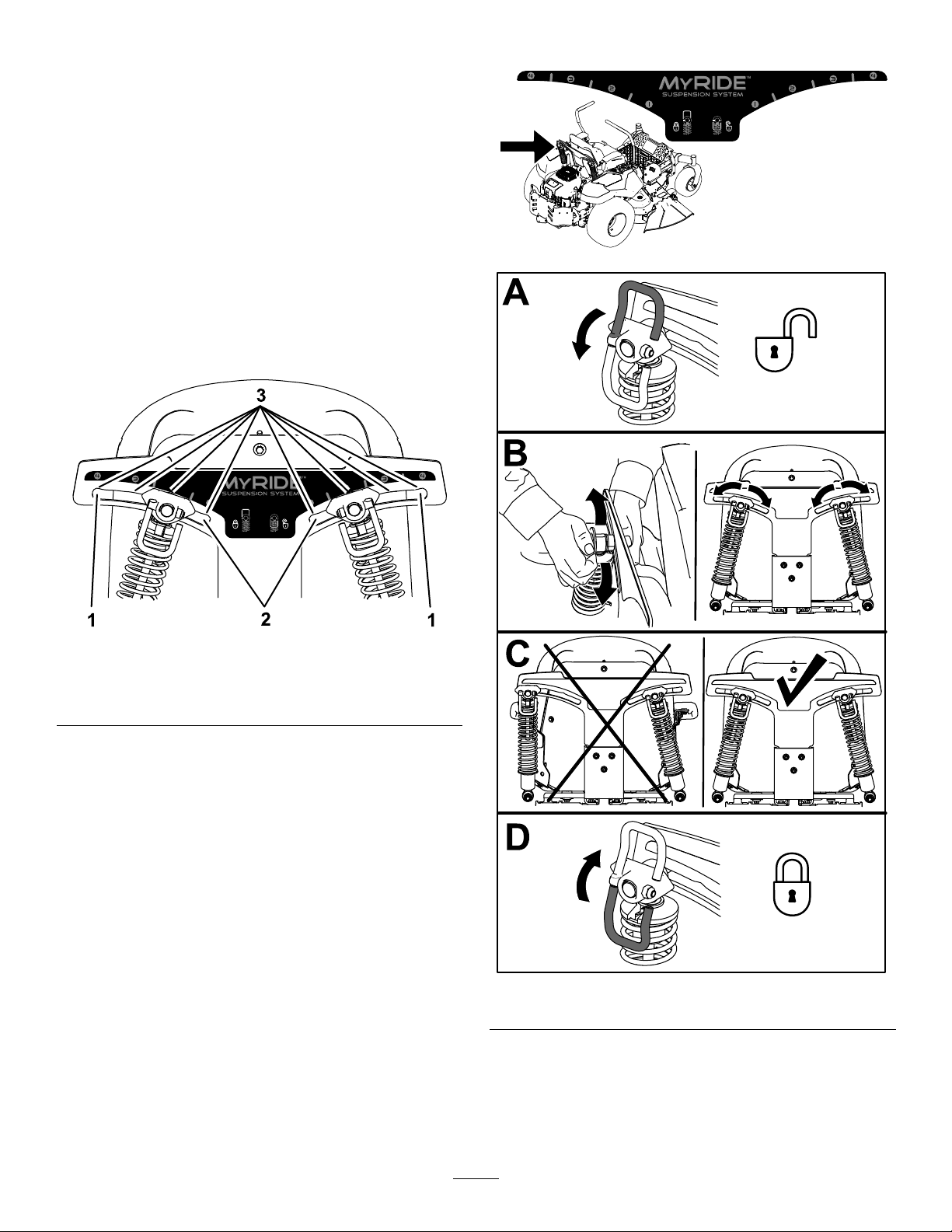
AdjustingtheMyRide™ SuspensionSystem
TheMyRide™suspensionsystemadjuststoprovidea
smoothandcomfortableride.Adjustingtherear2-shock
assembliesistheeasiestandquickestadjustmentforchanging
thesuspensionsystem.Positionthesuspensionsystemwhere
youaremostcomfortable.
Adjusttherear-shockassemblies(Figure12).
AdjustingtheRear-ShockAssemblies
Theslotsfortherear-shockassemblieshavedetentpositions
forreference.Youcanpositiontherear-shockassemblies
anywhereintheslot,notjustinthedetentpositions.
Thefollowinggraphicshowsthepositionforasoftorrm
rideandthedifferentdetentpositions(Figure11).
Figure11
1.Firmestposition3.Detentsintheslots
2.Softestposition
g195746
g195744
Note:Ensurethattheleftandrightrear-shockassemblies
arealwaysadjustedtothesamepositions.
g195745
Figure12
16
Page 17
g027252
B
A
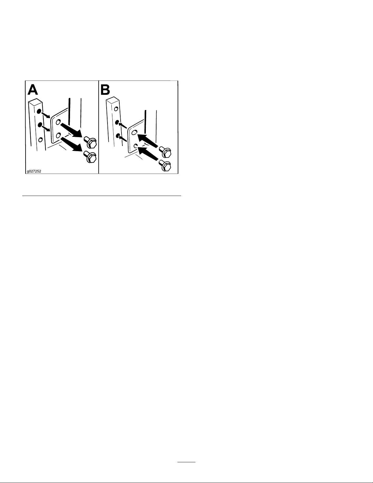
AdjustingtheMotion-Control Levers
AdjustingtheHeight
Youcanadjustthemotion-controllevershigherorlowerfor
maximumcomfort(Figure13).
Figure13
AdjustingtheTilt
Youcanadjustthemotion-controlleversforwardorrearward
foryourcomfort.
1.Loosentheupperboltholdingthecontrollevertothe
control-armshaft.
2.Loosenthelowerboltjustenoughtopivotthecontrol
leverforwardorrearward(Figure13).
3.Tightenbothboltstosecurethecontrolleverinthe
newposition.
4.Repeattheadjustmentfortheothercontrollever.
DuringOperation
DuringOperationSafety
GeneralSafety
•Theowner/operatorcanpreventandisresponsiblefor
accidentsthatmaycausepersonalinjuryorproperty
damage.
•Wearappropriateclothing,includingeyeprotection;
slip-resistant,substantialfootwear;andhearing
protection.Tiebacklonghairanddonotwearjewelry.
•Donotoperatethemachinewhileill,tired,orunderthe
inuenceofalcoholordrugs.
•Nevercarrypassengersonthemachineandkeep
bystandersandpetsawayfromthemachineduring
operation.
•Operatethemachineonlyingoodvisibilitytoavoidholes
orhiddenhazards.
g027252
•Avoidmowingonwetgrass.Reducedtractioncould
causethemachinetoslide.
•Ensurethatalldrivesareinneutral,theparkingbrake
isengaged,andyouareintheoperatingpositionbefore
youstarttheengine.
•Keepyourhandsandfeetawayfromthecuttingunits.
Keepclearofthedischargeopeningatalltimes.
•Lookbehindanddownbeforebackinguptobesureof
aclearpath.
•Usecarewhenapproachingblindcorners,shrubs,trees,
orotherobjectsthatmayobscureyourvision.
•Donotmowneardrop-offs,ditches,orembankments.
Themachinecouldsuddenlyrolloverifawheelgoes
overtheedgeoriftheedgegivesway.
•Stopthebladeswheneveryouarenotmowing.
•Stopthemachineandinspectthebladesafterstrikingan
objectorifthereisanabnormalvibrationinthemachine.
Makeallnecessaryrepairsbeforeresumingoperation.
•Slowdownandusecautionwhenmakingturnsand
crossingroadsandsidewalkswiththemachine.Always
yieldtheright-of-way.
•Disengagethedrivetothecuttingunitandshutoffthe
enginebeforeadjustingtheheightofcut(unlessyoucan
adjustitfromtheoperatingposition).
•Neverrunanengineinanareawhereexhaustgasesare
enclosed.
•Neverleavearunningmachineunattended.
•Beforeleavingtheoperatingposition(includingtoempty
thecatchersortounclogthechute),dothefollowing:
–Stopthemachineonlevelground.
–Disengagethepowertake-offandlowerthe
attachments.
–Engagetheparkingbrake.
–Shutofftheengineandremovethekey .
17
Page 18
–Waitforallmovingpartstostop.
•Donotoperatethemachinewhenthereistheriskof
lightning.
•Donotusethemachineasatowingvehicle.
OperatingtheParkingBrake
Alwaysengagetheparkingbrakewhenyoustopthemachine
orleaveitunattended.
•Donotchangethegovernorspeedoroverspeedthe
engine.
•UseaccessoriesandattachmentsapprovedbyToroonly.
SlopeSafety
•Slowdownthemachineanduseextracareonhillsides.
Travelupanddownonhillsides.Turfconditionscan
affectthestabilityofthemachine.
•Avoidturningthemachineonslopes.Ifyoumustturnthe
machine,turnitslowlyandgraduallydownhill,ifpossible.
•Donotturnthemachinesharply .Usecarewhenreversing
themachine.
•Useextracarewhileoperatingthemachinewith
attachments;theycanaffectthestabilityofthemachine.
•A2–postROPS(RolloverProtectionSystem)isavailable
forthemachineasanaccessory.AROPSisrecommended
ifyouwillbemowingnexttodrop-offs,nearwater,oron
steepbankswhichcouldresultinarollover.Contactan
AuthorizedServiceDealerformoredetails.
EngagingtheParkingBrake
WARNING
Theparkingbrakemaynotholdthemachine
parkedonaslopeandcouldcausepersonalinjury
orpropertydamage.
Donotparkonslopesunlessthewheelsare
chockedorblocked.
Toengagetheparkingbrake,pulluptheparkingbrakeuntilit
latchesintothedetentslot(Figure14).
g188778
Figure14
1.Pulluptheparkingbrake.
DisengagingtheParkingBrake
Todisengagetheparkingbrake,pulltheleveroutofthe
detentslotandtowardyou,thenpushitdown(Figure15).
Figure15
1.Pushtheparkingbrake
outofthedetentslotand
towardyou.
2.Pushtheparkingbrake
down.
g188777
18
Page 19

OperatingtheMower
G008945
G009174
G008959
1
2
OperatingtheThrottle
Blade-ControlSwitch(PTO)
Theblade-controlswitch(PTO)startsandstopsthemower
bladesandanypoweredattachments.
EngagingtheBlade-ControlSwitch
(PTO)
Figure16
Note:AlwaysengagethebladeswiththethrottleintheFAST
position(Figure17).
YoucanmovethethrottlecontrolbetweentheFASTand
SLOWpositions(Figure19).
AlwaysusetheFASTpositionwhenturningonthemower
deckwiththeblade-controlswitch(PTO).
g008945
Figure19
g187517
OperatingtheChoke
Usethechoketostartacoldengine.
1.Iftheengineiscold,usethechoketostarttheengine.
2.Pulluponthechokeknobtoengagethechokebefore
usingtheignitionswitch(Figure20).
3.Pushdownonthechoketodisengagethechokeafter
theenginehasstarted(Figure20).
g187516
Figure17
DisengagingtheBlade-ControlSwitch
(PTO)
g008959
Figure18
g009174
Figure20
1.ONposition2.OFFposition
19
Page 20

OperatingtheIgnitionSwitch
START
RUN
STOP
G008947
StartingandShuttingOffthe
1.TurntheignitionkeytotheSTARTposition(Figure21).
Note:Whentheenginesstarts,releasethekey.
Important:Donotengagestarterformorethan5
secondsatatime.Iftheenginefailstostart,allow
a15secondcool-downperiodbetweenattempts.
Failuretofollowtheseinstructionscanburnout
thestartermotor.
Note:Youmayneedmultipleattemptstostartthe
enginewhenyoustartitthersttimeafterthefuel
systemhasbeenwithoutfuelcompletely.
Figure21
Engine
StartingtheEngine
Note:Awarmorhotenginemaynotrequirechoking.
Important:Donotengagethestarterformorethan
5secondsatatime.Engagingthestartermotorfor
morethan5secondscandamagethestartermotor.If
theenginefailstostart,wait10secondsbeforeoperating
theenginestarteragain.
g008947
2.Turntheignitionkeytoshutofftheengine.
g189354
Figure22
ShuttingOfftheEngine
1.Disengagethebladesbymovingtheblade-control
switchtotheOFFposition(Figure20).
2.MovethethrottlelevertotheFASTposition.
3.TurntheignitionkeytotheOFFpositionandremove
thekey.
20
Page 21

UsingtheMotion-Control
G008952
Levers
DrivingForward
Note:Theenginestopswhenyoumovethetraction-control
withtheparkingbrakeengaged.
Tostop,pullthemotion-controlleverstotheNEUTRAL
position.
1.Disengagetheparkingbrake;refertoDisengagingthe
ParkingBrake(page18).
2.Movetheleverstothecenter,unlockedposition.
3.Togoforward,slowlypushthemotion-controllevers
forward(Figure24).
Figure23
1.Motion-control
lever—NEUTRAL-LOCK
position
2.Center,unlockedposition5.Frontofmachine
3.Forward
4.Backward
DrivingtheMachine
Thedrivewheelsturnindependently,poweredbyhydraulic
motorsoneachaxle.Youcanturn1sideinreversewhileyou
turntheotherforward,causingthemachinetospinrather
thanturn.Thisgreatlyimprovesthemachinemaneuverability
butmayrequiresometimeforyoutoadapttohowitmoves.
Thethrottlecontrolregulatestheenginespeedasmeasured
inrpm(revolutionsperminute).Placethethrottlecontrolin
theFASTpositionforbestperformance.Alwaysoperatein
thefullthrottlepositionwhenmowing.
CAUTION
Themachinecanspinveryrapidly ,whichmay
causeyoutolosecontrolofmachine,resultingin
personalinjuryordamagetomachine.
g004532
g008952
Figure24
•Usecautionwhenmakingturns.
•Slowthemachinedownbeforemakingsharp
turns.
21
Page 22

DrivingBackward
G008953
1.Movetheleverstothecenter,unlockedposition.
2.Togobackward,slowlypullthemotion-controllevers
rearward(Figure25).
Figure25
Thefollowingareonlyrecommendationsforuse.
Adjustmentsvarybygrasstype,moisturecontent,andthe
heightofthegrass.
Suggested
uses:
ParkingX
Heavy,wet
grass
TrainingX
BaggingX
MulchingX
Normal
mowing
TransportX
TrimTowMow
X
X
Trim
Thisisthelowestspeed.Thesuggestedusesforthisspeed
areasfollows:
•Parking
•Heavy,wetgrassmowingconditions
g008953
•Training
Tow
UsingtheSmartSpeed
TM
ControlSystem
TheSmartSpeed
rightoftheoperatingposition(Figure26),givesyouachoice
todrivethemachineat3groundspeedranges—trim,tow ,
andmow .
1.Smart-speedlever
TM
Control-Systemlever,locatedtothe
Figure26
Thisisthemediumspeed.Thesuggestedusesforthisspeed
areasfollows:
•Bagging
•Mulching
Mow
Thisisthefastestspeed.Thesuggestedusesforthisspeed
areasfollows:
•Normalmowing
•Transportingthemachine
StoppingtheMachine
Tostopthemachine,movethetraction-controlleversto
neutral,andthenmovethemtothelockedposition,disengage
theblade-controlswitch(PTO),andturntheignitionkeyto
theOFFposition.
Engagetheparkingbrakewhenyouleavethemachine;refer
g197125
toEngagingtheParkingBrake(page18).Rememberto
removethekeyfromtheignitionswitch.
CAUTION
Tochangespeeds,dothefollowing:
1.Movethemotion-controlleverstoneutralandoutward
totheNEUTRAL-LOCKposition.
2.Disengagetheblade-controlswitch.
3.Adjustthelevertothedesiredposition.
Childrenorbystandersmaybeinjuredifthey
moveorattempttooperatethemachinewhileitis
unattended.
Alwaysremovetheignitionkeyandengage
theparkingbrakewhenleavingthemachine
unattended,evenifjustforafewminutes.
22
Page 23

UsingtheSideDischarge
g024409
AdjustingtheHeightofCut
Themowerhasahingedgrassdeectorthatdisperses
clippingstothesideanddowntowardtheturf.
DANGER
Withoutagrassdeector,dischargecover,ora
completegrass-catcherassemblymountedin
place,youandothersareexposedtobladecontact
andthrowndebris.Contactwithrotatingmower
blade(s)andthrowndebriswillcauseinjuryor
death.
•Neverremovethegrassdeectorfromthemower
becausethegrassdeectorroutesmaterialdown
towardtheturf.Ifthegrassdeectorisever
damaged,replaceitimmediately .
•Neverputyourhandsorfeetunderthemower.
•Nevertrytoclearthedischargeareaormower
bladesunlessyoumovetheblade-controlswitch
(PTO)totheOFFposition,rotatetheignition
keytotheOFFposition,andremovethekey.
•Makesurethatthegrassdeectorisinthedown
position.
Themachineisequippedwithafootpedaldeck-liftsystem.
Youcanusethefootpedaltoliftthedeckbrieytoavoid
obstaclesorlockthedeckinthehighestheightofcutor
transportposition.Youcanusetheheight-of-cutleverwith
thefootpedaltolockthedeckinaspeciccuttingheight.
UsingtheFootPedalDeck-LiftSystem
•Pressthedeck-liftpedaldowntoraisethedeck;continue
topressthepedaluntilthedecklocksinthetransport
position(Figure27).
•Pushonthedeck-liftpedalwithyourfootandpullthe
transportlockhandlerearwardtodisengagethetransport
lock(Figure27).
Figure27
TransportLockPosition
AdjustingtheHeightofCut
Youcanadjusttheheightofcutfrom38to114mm(1-1/2
to4-1/2inches)in6mm(1/4inch)incrementsbyrelocating
theheight-of-cutpinintodifferentholelocations.
1.Pushonthedeck-liftpedalwithyourfootandraise
themowerdecktothetransport-lockposition(also
the114mm(4-1/2inches)cuttingheightposition)as
showninFigure28.
2.Toadjust,removethepinfromtheheight-of-cut
bracket(Figure28).
3.Selectaholeintheheight-of-cutsystemcorresponding
tothedesiredheightofcutandinsertthepin(Figure
28).
23
g024409
Page 24

4.Pushonthedeck-liftpedalwithyourfootandpull
g029955
thehandlerearwardtodisengagethetransportlock
(Figure27).
AdjustingtheAnti-Scalp Rollers
5.Lowerthedeckslowlyuntilthelevermakescontact
withthepin.
Figure28
1.Deck-liftpedal
2.Handle
3.Pin
4.Height-of-cutpositions
Wheneveryouchangetheheight-of-cut,itisrecommended
toadjusttheheightoftheanti-scalprollers.
1.Disengagetheblade-controlswitch(PTO),movethe
motion-controlleverstotheNEUTRAL-LOCKposition,
andengagetheparkingbrake.
2.Shutofftheengine,removethekey ,andwaitforall
movingpartstostopbeforeleavingtheoperating
position.
3.Adjusttheanti-scalprollersasshowninFigure29.
g188850
g029955
Figure29
1.Anti-scalproller4.Flangenut
2.Spacer
3.Bushing
5.Bolt
Convertingthe48-inchMower DecktoSideDischarge
Themowerdeckandmowerbladesshippedwiththemachine
weredesignedforoptimummulchingandside-discharge
performance.
Installthefastenersintothesameholesinthedeckthatthey
wereoriginallyremovedfrom.Thisensuresthatnoholesare
leftopenwhenoperatingthemowerdeck.
DANGER
Openholesinthemowerexposeyouandothersto
throwndebris.Debristhrownoutofholesinthe
mowercancauseinjury.
•Neveroperatethemowerwithouthardware
mountedinallholesinthemower.
•Installhardwareinmountingholeswhenthe
bafeisremoved.
RemovingtheMulchingBafe
1.Parkthemachineonalevelsurfaceanddisengagethe
blade-controlswitch.
24
Page 25

2.Movethemotion-controlleversoutwardtothe
G011149
1
1
2
3
4
G010704
1
2
3
NEUTRAL-LOCKposition,engagetheparkingbrake,
shutofftheengine,removethekey,andwaitforall
movingpartstostopbeforeleavingtheoperating
position.
3.Removethemowerdeck;refertoRemovingtheMower
Deck(page47).
4.Removethe2locknuts(5/16inch)securedtothe
weldedpostsoftheleftbafeonthetopofthemower
deckatthecenterandleftofcenterpositions(Figure
30).
8.Removethe2locknuts(5/16inch)tosecuringthe
weldedpostsoftherightbafetothetopofthe
mowerdeckatthecenterandrightofcenterpositions
(Figure32).
Note:Removetherightbafefromthemowerdeck.
g010704
Figure32
Figure30
1.Locknut(5/16inch)3.Leftbafe
2.Carriagebolt(5/16x3/4
inch)
4.Installthefastenershere.
5.Removethecarriageboltandlocknutonthesidewall
ofthemowerdecksecuringtheleftbafetothedeck.
6.Removetheleftbafefromthemowerdeckasshown
inFigure30.
7.Removethe2carriagebolts(5/16x3/4inch)and
2locknuts(5/16inch)securingtheassembledright
bafeandbafeguardtothemowerdeck(Figure31).
g011149
1.Locknut(5/16inch)3.Weldedposts(rightbafe)
2.Rightbafe
9.Locatethecutoffbafeintheloosepartsbagand
removethefastenersattherearholesofthedischarge
plate(Figure33).
g190734
Figure33
Figure31
1.Carriagebolt(5/16x3/4
inch)
2.Locknut(5/16inch)4.Bafeguard
3.Rightbafe
g191136
1.Carriagebolts(existing)3.Cutoffbafe(loose)
2.Rearholesinthe
dischargeplate
4.Locknuts(existing)
10.Installthebafeatthesidedischargeopeningonthe
mowerdeck.
25
Page 26

11.Usethefastenersremovedtosecurethecutoffbafe
G011149
1
1
2
3
4
tothedeck.
12.Installthemowerdeck;refertoInstallingtheMower
Deck(page48).
5.Removethecarriageboltandlocknutonthesidewall
ofthemowerdecksecuringtheleftbafetothedeck
(Figure34).
6.Removetheleftbafefromthemowerdeck(Figure
34).
Convertingthe54-inchMower DecktoSideDischarge
Installthefastenersintothesameholesinthedeckfrom
whichtheywereremoved.Thisensuresthatnoholesareleft
openwhenoperatingthemowerdeck.
DANGER
Openholesinthemowerexposeyouandothersto
throwndebris.Debristhrownoutofholesinthe
mowercancauseinjury.
•Neveroperatethemowerwithouthardware
mountedinallholesinthemower.
•Installhardwareinmountingholeswhenyou
removethebafe.
RemovingtheMulchingBafe
1.Parkthemachineonalevelsurfaceanddisengagethe
blade-controlswitch.
2.Movethemotion-controlleversoutwardtothe
NEUTRAL-LOCKposition,engagetheparkingbrake,
shutofftheengine,removethekeyfromthekey
switch,andwaitforallmovingpartstostopbefore
leavingtheoperatingposition.
3.Removethemowerdeck;refertoRemovingtheMower
Deck(page47).
4.Removethe3locknuts(5/16inch)securedtothe
weldedpostsoftheleftbafeonthetopofthemower
deckatthecenter,leftofcenter,andleftpositions
(Figure34).
7.Locatethe2boltsinloosepartsandusetheexisting
locknutsandinstallthesefastenersintotheholes
showninFigure34onthemowerdecktoprevent
yingdebris.
Note:Installtheboltupward,throughtheunderside
ofthedeckanduseanexistinglocknuttosecurefrom
thetopside.
WARNING
Openholesinthemowerexposeyouand
otherstothrowndebriswhichcancause
severeinjury.
•Neveroperatethemowerwithouthardware
mountedinallholesinthemowerhousing.
•Installthehardwareinthemountingholes
whenyouremovethemulchingbafe.
8.Removethecarriagebolt(5/16x3/4inch)andlocknut
(5/16inch)ontherearwallofthemowerdecksecuring
thebafetothedeck(Figure35).
g011149
Figure34
1.Locknut(5/16inch)3.Leftbafe
2.Carriagebolt(5/16x3/4
inch)
4.Installthefastenershere.
26
Page 27

Figure35
G010704
1
2
3
1.Locknuts—frontof
dischargeplate(install
afterbafeisremoved)
2.Hex-headbolt—forward
holeindeck(installafter
bafeisremoved)
3.Locknut—forwardholein
deck(installafterbafeis
removed)
4.Carriagebolts—frontof
dischargeplate(install
afterbafeisremoved)
5.Bafeguard—54-inch
decks
6.Locknut(5/16inch)
7.Carriagebolt(5/16x3/4
inch)
9.Locatethebafeguardatthefrontedgeoftheside
dischargeopening(Figure35).
10.Removethefastenerssecuringthebafeguardandthe
rightbafetothemowerdeck(Figure35).
Note:Removethebafeguardandretainallfasteners.
11.Removethe2locknuts(5/16inch)securingthewelded
postsoftherightbafetothetopofthemowerdeck
atcenterandrightofcenterpositions(Figure36).
g010704
g190737
1.Locknut(5/16inch)3.Weldedposts(rightbafe)
2.Rightbafe
Figure36
12.Removethecarriageboltandlocknutsecuringtheright
bafetothetopofthemowerdeckandremovethe
rightbafefromthemowerdeck(Figure36).
13.Installthefastenersremovedpreviouslyatthefront
holesinthedischargeplateandforwardholeinthe
deck(Figure35).
14.Locatethecutoffbafeintheloosepartsbag,remove
thefastenersattherearholesofthedischargeplate,
andinstallthebafeattheside-dischargeopeningon
themowerdeck(Figure37).
g190735
Figure37
1.Carriagebolts3.Cutoffbafe
2.Rearholesinthe
dischargeplate
27
4.Locknuts
Page 28

15.Usethefastenersremovedtosecurethecutoffbafe
tothedeck.
OperatingTips
16.Installthemowerdeck;refertoInstallingtheMower
Deck(page48).
UsingAttachmentsand Accessories
UseonlyToroapprovedattachmentsandaccessories.
Ifyouattachabuckettotheengineguard,useanylonstrap
tosecureit.
Important:Thebucketweightimpactsthestabilityof
themachine.Ifyouarecarryingmorethantheweight
listedinthetablebelowinabucketattachedtothe
engineguard,youmustequipyourmachinewiththe
Bucket-SupportKit.
ContactyourauthorizedToroservicedealer.
DeckSize
48-inchdeck
54-inchdeck
Maximumweightperbucket
withouttheBucket-Support
Kit
1.1kg(2.5lb)
1.1kg(2.5lb)
UsingtheFastThrottleSetting
Forbestmowingandmaximumaircirculation,operatethe
engineattheFASTposition.Airisrequiredtothoroughlycut
grassclippings,sodonotsettheheight-of-cutsolowasto
totallysurroundthemowerinuncutgrass.Alwaystrytohave
1sideofthemowerfreefromuncutgrass,whichallowsair
tobedrawnintothemower.
CuttingaLawnfortheFirstTime
Cutgrassslightlylongerthannormaltoensurethatthe
cuttingheightofthemowerdoesnotscalpanyuneven
ground.However,thecuttingheightusedinthepastis
generallythebestonetouse.Whencuttinggrasslongerthan
15cm(6inches)tall,youmaywanttocutthelawntwiceto
ensureanacceptablequalityofcut.
CuttingaThirdoftheGrassBlade
Itisbesttocutonlyaboutathirdofthegrassblade.Cutting
morethanthatisnotrecommendedunlessgrassissparse,or
itislatefallwhengrassgrowsmoreslowly.
AlternatingtheMowingDirection
Alternatethemowingdirectiontokeepthegrassstanding
straight.Thisalsohelpsdisperseclippingswhichenhances
decompositionandfertilization.
MowingatCorrectIntervals
Grassgrowsatdifferentratesatdifferenttimesoftheyear.
Tomaintainthesamecuttingheight,mowmoreofteninearly
spring.Asthegrassgrowthrateslowsinmidsummer,mow
lessfrequently .Ifyoucannotmowforanextendedperiod,
rstmowatahighcuttingheight,thenmowagain2days
lateratalowerheightsetting.
UsingaSlowerCuttingSpeed
Toimprovecutquality,useaslowergroundspeedincertain
conditions.
AvoidingCuttingTooLow
Whenmowinguneventurf,raisethecuttingheighttoavoid
scalpingtheturf.
StoppingtheMachine
Ifyoumuststoptheforwardmotionofthemachinewhile
mowing,aclumpofgrassclippingsmaydropontoyour
lawn.Toavoidthis,moveontoapreviouslycutareawiththe
bladesengagedoryoucandisengagethemowerdeckwhile
movingforward.
28
Page 29

KeepingtheUndersideoftheMower
Clean
AfterOperation
Cleanclippingsanddirtfromtheundersideofthemower
aftereachuse.Ifgrassanddirtbuildupinsidethemower,
cuttingqualitywilleventuallybecomeunsatisfactory.
MaintainingtheBlade(s)
Maintainasharpbladethroughoutthecuttingseasonbecause
asharpbladecutscleanlywithouttearingorshreddingthe
grassblades.Tearingandshreddingturnsgrassbrownat
theedges,whichslowsgrowthandincreasesthechanceof
disease.Checkthemowerbladesaftereachuseforsharpness,
andforanywearordamage.Filedownanynicksandsharpen
thebladesasnecessary.Ifabladeisdamagedorworn,replace
itimmediatelywithagenuineTororeplacementblade.
AfterOperationSafety
GeneralSafety
•Cleangrassanddebrisfromthecuttingunits,mufers,
andenginecompartmenttohelppreventres.Cleanup
oilorfuelspills.
•Shutoffthefuelbeforestoringortransportingthe
machine.
•Disengagethedrivetotheattachmentwheneveryouare
transportingornotusingthemachine.
•Usefull-widthrampsforloadingthemachineintoa
trailerortruck.
•Tiethemachinedownsecurelyusingstraps,chains,cable,
orropes.Bothfrontandrearstrapsshouldbedirected
downandoutwardfromthemachine.
•Allowtheenginetocoolbeforestoringthemachinein
anyenclosure.
•Neverstorethemachineorfuelcontainerwherethereis
anopename,spark,orpilotlight,suchasonawater
heateroronotherappliances.
29
Page 30

PushingtheMachinebyHand
TransportingtheMachine
Important:Alwayspushthemachinebyhand.Donot
towthemachine,becausedamagemayoccur.
PushingtheMachine
1.Parkthemachineonalevelsurface,anddisengagethe
blade-controlswitch.
2.Engagetheparkingbrake,shutofftheengine,and
waitforallmovingpartstostopbeforeleavingthe
operatingposition.
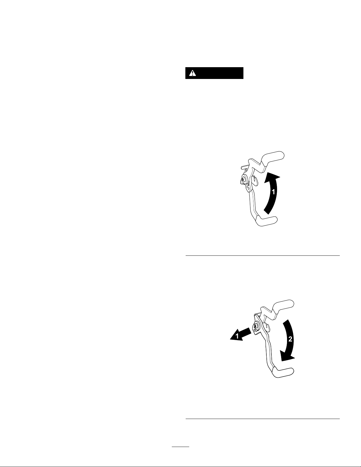
3.Locatethebypassleversontheframeonbothsidesof
theengine.
4.Movethebypassleversforwardthroughthekeyhole
anddowntolocktheminplace(Figure38).
Note:Dothisforeachlever.
5.Disengagetheparkingbrake.
Note:Donotstartthemachine.
Useaheavy-dutytrailerortrucktotransportthemachine.
Ensurethatthetrailerortruckhasallnecessarybrakes,
lighting,andmarkingasrequiredbylaw .Pleasecarefullyread
allthesafetyinstructions.Knowingthisinformationcould
helpyou,yourfamily,pets,orbystandersavoidinjury.
WARNING
Drivingonthestreetorroadwaywithout
turnsignals,lights,reectivemarkings,ora
slow-moving-vehicleemblemisdangerousandcan
leadtoaccidents,causingpersonalinjury.
Donotdrivethemachineonapublicstreetor
roadway.
1.Ifyouareusingatrailer,connectittothetowing
vehicleandconnectthesafetychains.
2.Ifapplicable,connectthetrailerbrakes.
3.Loadthemachineontothetrailerortruck.
4.Shutofftheengine,removethekey,setthebrake,and
closethefuelvalve.
1.Bypasslever
2.Leverpositionforpushing
themachine
5.Tiedownthemachinenearthefrontcasterwheelsand
therearbumper(Figure39).
g027708
Figure39
g188854
Figure38
3.Leverpositionfor
operatingthemachine
OperatingtheMachine
Movethebypassleversrearwardthroughthekeyholeand
downtolocktheminplaceasshowninFigure38.
Note:Dothisforeachlever.
30
Page 31

LoadingtheMachine
g027996
5
1
2
6
Useextremecautionwhenloadingorunloadingmachines
ontoatraileroratruck.Useafull-widthrampthatiswider
thanthemachineforthisprocedure.Backthemachineupthe
rampanddriveitforwarddowntheramp(Figure40).
Figure40
g027995
1.Backthemachineupthe
ramp.
2.Drivethemachineforward
downtheramp.
Important:Donotusenarrowindividualrampsfor
eachsideofthemachine.
WARNING
Loadingamachineontoatrailerortruckincreases
thepossibilityoftip-overandcouldcauseserious
injuryordeath(Figure41).
•Useextremecautionwhenoperatingamachine
onaramp.
•Useonlyafull-widthramp;donotuseindividual
rampsforeachsideofthemachine.
•Donotexceeda15-degreeanglebetweenthe
rampandthegroundorbetweentherampand
thetrailerortruck.
•Ensurethatthelengthoframpisatleast4times
aslongastheheightofthetrailerortruckbed
totheground.Thisensuresthattherampangle
doesnotexceed15degreesonatground.
1.Full-widthrampinstowed
position
2.Sideviewoffull-width
rampinloadingposition
3.Notgreaterthan
15degrees
g027996
Figure41
4.Rampisatleast4times
aslongastheheightof
thetrailerortruckbedto
theground
5.H=heightofthetraileror
truckbedtotheground
6.Trailer
•Backuprampsanddriveforwarddownramps.
•Avoidsuddenaccelerationordecelerationwhile
drivingthemachineonarampasthiscould
causealossofcontroloratip-oversituation.
31
Page 32

Maintenance
Note:Determinetheleftandrightsidesofthemachinefromthenormaloperatingposition.
RecommendedMaintenanceSchedule(s)
MaintenanceService
Interval
Aftertherst5hours
Beforeeachuseordaily
Aftereachuse
Every25hours
Every100hours
Every200hours
MaintenanceProcedure
•Changetheengineoil.
•Checkthesafety-interlocksystem.
•Checktheaircleanerfordirty,loose,ordamagedparts.
•Checktheengine-oillevel.
•Cleantheairintakescreen.
•Inspecttheblades.
•Inspectthegrassdeectorfordamage.
•Cleanthemower-deckhousing.
•Cleantheair-cleanerfoamelement(moreoftenindusty,dirtyconditions).
•Checktirepressure.
•Checkthebeltsforwearorcracks.
•Replacetheair-cleanerfoamelement(moreoftenindusty,dirtyconditions).
•Servicetheair-cleanerpaperelement(moreoftenindusty,dirtyconditions).
•Changetheengineoil(moreoftenindusty,dirtyconditions).
•Changetheoillter(moreoftenindusty,dirtyconditions).
•Checkthesparkplug(s).
•Checkthein-linefuellter.
•Replacetheair-cleanerpaperelement(moreoftenindusty,dirtyconditions).
•Replacethesparkplug(s).
•Replacethein-linefuellter.
•Chargethebatteryanddisconnectthebatterycables.
Beforestorage
•Performallmaintenanceprocedureslistedabovebeforestorage.
•Paintanychippedsurfaces.
CAUTION
Ifyouleavethekeyinthekeyswitch,someonecouldaccidentlystarttheengineandseriouslyinjure
youorotherbystanders.
Removethekeyfromthekeyswitchbeforeyouperformanymaintenance.
32
Page 33

Pre-Maintenance
Procedures
MaintenanceandStorage Safety
•Beforerepairingthemachinedothefollowing:
–Disengagethedrives.
–Engagetheparkingbrake.
–Shutofftheengineandremovethekey .
–Disconnectthespark-plugwire.
•Parkthemachineonalevelsurface.
•Cleangrassanddebrisfromthecuttingunit,drives,
mufers,andenginetohelppreventres.
•Cleanupoilorfuelspills.
•Lettheenginecoolbeforestoringthemachine.
•Donotstorethemachineorfuelnearamesordrain
thefuelindoors.
•Donotallowuntrainedpersonneltoservicethemachine.
•Usejackstandstosupportthemachineand/or
componentswhenrequired.
ReleasingtheMower-Deck Curtain
Loosenthe2bottomboltsofthecurtaintoaccessthetopof
themowerdeck(Figure42).
Figure42
1.Bottombolt
Note:Alwaystightentheboltstoconnectthecurtainafter
maintenance.
2.Curtain
g027794
•Carefullyreleasepressurefromcomponentswithstored
energy.
•Disconnectthebatteryorremovethespark-plugwire
beforemakinganyrepairs.Disconnectthenegative
terminalrstandthepositiveterminallast.Connectthe
positiveterminalrstandnegativelast.
•Usecarewhencheckingtheblades.Wraptheblade(s)
orwearthicklypaddedgloves,andusecautionwhen
servicingthem.Onlyreplaceblades;donotstraighten
orweldthem.
•Keepyourhandsandfeetawayfrommovingparts.
Ifpossible,donotmakeadjustmentswiththeengine
running.
•Keepallpartsingoodworkingconditionandallhardware
tightened,especiallytheblade-attachmentbolts.Replace
allwornordamageddecals.
•Neverinterferewiththeintendedfunctionofasafety
deviceorreducetheprotectionprovidedbyasafety
device.Checktheirproperoperationregularly.
•Toensureoptimumperformanceandcontinuedsafety
certicationofthemachine,useonlygenuineToro
replacementpartsandaccessories.Replacementparts
andaccessoriesmadebyothermanufacturerscouldbe
dangerous,andsuchusecouldvoidtheproductwarranty.
•Checktheparkingbrakeoperationfrequently.Adjustand
serviceasrequired.
33
Page 34

EngineMaintenance
g027800
g027801
g027802
WARNING
Contactwithhotsurfacesmaycausepersonal
injury.
Keepyourhands,feet,face,clothing,andother
bodypartsawaythemuferandotherhotsurfaces.
EngineSafety
Shutofftheenginebeforecheckingtheoiloraddingoilto
thecrankcase.
ServicingtheAirCleaner
ServiceInterval:Beforeeachuseordaily
Note:Servicetheaircleanermorefrequently(everyfew
hours)ifoperatingconditionsareextremelydustyorsandy.
RemovingtheElements
1.Parkthemachineonalevelsurfaceanddisengagethe
blade-controlswitch(PTO).
2.Engagetheparkingbrake,shutofftheengine,remove
thekey ,andwaitforallmovingpartstostopbefore
leavingtheoperatingposition.
3.Cleanaroundtheair-cleanercovertopreventdirtfrom
gettingintotheengineandcausingdamage.
4.Liftthecoverandrotatetheair-cleanerassemblyout
oftheengine(Figure43).
g027800
g027801
Figure43
5.Removethefoamelementfromthepaperelement
(Figure44).
g027802
Figure44
ServicingtheFoamElement
ServiceInterval:Every25hours/Monthly(whichever
comesrst)—Cleantheair-cleanerfoam
element(moreoftenindusty,dirty
conditions).
Every100hours/Yearly(whichevercomes
rst)—Replacetheair-cleanerfoamelement(more
oftenindusty,dirtyconditions).
Washthefoamelementwithwaterandreplacethefoam
elementifitisdamaged.
34
Page 35

ServicingthePaperElement
SAE 5W -30, 10W -30
SAE 30
SYNTHETIC 5W -20, 5W -30, 10W -30
g029683
ServiceInterval:Every100hours/Yearly(whichevercomes
rst)—Servicetheair-cleanerpaper
element(moreoftenindusty,dirty
conditions).
Every200hours/Every2years(whichevercomes
rst)—Replacetheair-cleanerpaperelement(more
oftenindusty,dirtyconditions).
1.Lightlytaptheelementonaatsurfacetoremovedust
anddirt.
2.Inspecttheelementfortears,anoilylm,anddamage
totheseal.
Important:Donotcleanthepaperelement
withpressurizedairorliquids,suchassolvent,
gasoline,orkerosene.Replacethepaperelement
ifitisdamagedorcannotbecleanedthoroughly .
ServicingtheEngineOil
OilType:Detergentoil(APIserviceSF,SG,SH,SJ,orSL)
CrankcaseCapacity:withlter—2.4L(2.5USqt)
1.Parkthemachineonalevelsurface,disengagethe
blade-controlswitch,shutofftheengine,engage
parkingbrake,andremovethekey.
2.Makesurethattheengineisshutoff,level,andiscool,
sothattheoilhashadtimetodrainintothesump.
3.Tokeepdirt,grassclippings,etc.,outoftheengine,
cleantheareaaroundtheoil-llcapanddipstickbefore
removingit(Figure46).
4.Shutofftheengine,removethekey ,andwaitforall
movingpartstostopbeforeleavingtheoperating
position.
Viscosity:Seethetablebelow.
Figure45
CheckingtheEngine-OilLevel
ServiceInterval:Beforeeachuseordaily
Note:Checktheoilwhentheengineiscold.
WARNING
g029683
g193541
Figure46
Contactwithhotsurfacesmaycausepersonal
injury.
Keepyourhands,feet,face,clothing,andother
bodypartsawaythemuferandotherhotsurfaces.
Important:Ifyouoverllorunderlltheengine
crankcasewithoilandruntheengine,youmaydamage
theengine.
35
Page 36

g027799
A
B
C
D
E
F
G
H
g029570
ChangingtheEngineOilandOilFilter
ServiceInterval:Aftertherst5hours/Aftertherst
month(whichevercomesrst)—Change
theengineoil.
Every100hours/Yearly(whichevercomes
rst)—Changetheengineoil(moreoftenindusty,
dirtyconditions).
Every100hours/Yearly(whichevercomes
rst)—Changetheoillter(moreoftenindusty,dirty
conditions).
Note:Changetheengine-oilltermorefrequentlywhen
operatingconditionsareextremelydustyorsandy.
Note:Disposeoftheusedoilatarecyclingcenter.
1.Parkthemachineonalevelsurfacetoensurethatthe
oildrainscompletely.
2.DisengagethePTOandensurethattheparkingbrake
isengaged.
3.Shutofftheengine,removethekey ,andwaitforall
movingpartstostopbeforeleavingtheoperating
position.
g027799
4.Draintheengineoil.
g029570
Figure47
36
Page 37

5.Changetheengine-oillter(Figure48).
B
A
C D
E
F
3/4
g027477
Note:Ensurethattheoil-ltergaskettouchesthe
engineandthenturnthelteranextra3/4turn.
g193530
Figure49
6.Slowlypourapproximately80%ofthespeciedoil
intothellertubeandslowlyaddtheadditionaloilto
bringittotheFullmark(Figure49).
Figure48
ServicingtheSparkPlug
ServiceInterval:Every100hours/Yearly(whichevercomes
rst)—Checkthesparkplug(s).
g027477
Every200hours/Every2years(whichevercomes
rst)—Replacethesparkplug(s).
Makesurethattheairgapbetweenthecenterandside
electrodesiscorrectbeforeinstallingthesparkplug.Use
aspark-plugwrenchforremovingandinstallingthespark
plug(s)andagappingtool/feelergaugetocheckandadjust
theairgap.Installanewsparkplug(s)ifnecessary.
Type:Champion
Airgap:0.76mm(0.03inch)
®
RN9YCorNGK
®
BPR6ES
RemovingtheSparkPlug
1.DisengagethePTOandensurethattheparkingbrake
isengaged.
2.Shutofftheengine,removethekey ,andwaitforall
movingpartstostopbeforeleavingtheoperating
position.
37
Page 38

B
A
g027478
Figure50
B
A
g027479
B
A
25-30 N-m
18.5-22.1 ft-lb
g027960
C
D
Note:Duetothedeeprecessaroundthesparkplug,
blowingoutthecavitywithcompressedairisthemost
effectivemethodforcleaning.Thesparkplugismost
accessiblewhentheblowerhousingisremovedfor
cleaning.
CheckingtheSparkPlug
InstallingtheSparkPlug
Tightenthesparkplug(s)to25to30N∙m(18.5to22.1ft-lb).
g027478
Important:Donotcleanthesparkplug(s).Always
replacethesparkplug(s)whenithas:ablackcoating,
wornelectrodes,anoilylm,orcracks.
Ifyouseelightbrownorgrayontheinsulator,theengineis
operatingproperly .Ablackcoatingontheinsulatorusually
meanstheaircleanerisdirty.
Setthegapto0.76mm(0.03inch).
Figure51
g027960
Figure52
CleaningtheCoolingSystem
Cleantheairintakescreenfromgrassanddebrisbeforeeach
use.
1.Disengagetheblade-controlswitchandapplythe
parkingbrake.
2.Shutofftheengine,removethekey ,andwaitforall
movingpartstostopbeforeleavingtheoperating
position.
3.Removetheairlterfromtheengine.
g027479
4.Removetheengineshroud.
5.Topreventdebrisenteringtheairintake,installtheair
ltertothelterbase.
6.Cleandebrisandgrassfromtheparts.
7.Removetheairlterandinstalltheengineshroud.
8.Installtheairlter.
38
Page 39

FuelSystem
g027939
Maintenance
DANGER
Incertainconditions,fuelisextremelyammable
andhighlyexplosive.Areorexplosionfromfuel
canburnyou,others,andcandamageproperty.
•Performanyfuel-relatedmaintenancewhenthe
engineiscold.Dothisoutdoorsinanopenarea.
Wipeupanyfuelthatspills.
•Neversmokewhendrainingfuel,andstayaway
fromanopenameorwhereasparkmayignite
thefuelfumes.
ReplacingtheIn-LineFuel Filter
ServiceInterval:Every100hours/Yearly(whichevercomes
rst)—Checkthein-linefuellter.
g027939
Every200hours/Every2years(whichevercomes
rst)—Replacethein-linefuellter.
Neverinstalladirtylterifitisremovedfromthefuelline.
1.Parkthemachineonalevelsurfaceanddisengagethe
blade-controlswitch.
2.Ensurethatthebrakeisengaged,shutofftheengine,
removethekey ,andwaitforallmovingpartstostop
beforeleavingtheoperatingposition.
g033082
Figure53
39
Page 40

ElectricalSystem
Maintenance
ElectricalSystemSafety
•Disconnectthebatterybeforerepairingthemachine.
Disconnectthenegativeterminalrstandthepositive
last.Connectthepositiveterminalrstandthenegative
last.
•Chargethebatteryinanopen,well-ventilatedarea,away
fromsparksandames.Unplugthechargerbefore
connectingordisconnectingthebattery.Wearprotective
clothinganduseinsulatedtools.
WARNING
CALIFORNIA
Proposition65Warning
Batteryposts,terminals,andrelated
accessoriescontainleadandleadcompounds,
chemicalsknowntotheStateofCalifornia
tocausecancerandreproductiveharm.
Washhandsafterhandling.
ServicingtheBattery
RemovingtheBattery
WARNING
Batteryterminalsormetaltoolscouldshortagainst
metalmachinecomponentscausingsparks.Sparks
cancausethebatterygassestoexplode,resulting
inpersonalinjury.
•Whenremovingorinstallingthebattery,donot
allowthebatteryterminalstotouchanymetal
partsofthemachine.
•Donotallowmetaltoolstoshortbetween
thebatteryterminalsandmetalpartsofthe
machine.
g190587
Figure54
1.Batterycover2.Fasteners
4.Disconnectthenegative(black)groundcablefromthe
batterypost(Figure55).
Note:Retainallfasteners.
WARNING
Incorrectbattery-cableroutingcoulddamage
themachineandcablescausingsparks.
Sparkscancausethebatterygassesto
explode,resultinginpersonalinjury.
•Alwaysdisconnectthenegative(black)
batterycablebeforedisconnectingthe
positive(red)cable.
•Alwaysconnectthepositive(red)battery
cablebeforeconnectingthenegative
(black)cable.
5.Slidetherubbercoverupthepositive(red)cable.
6.Disconnectthepositive(red)cablefromthebattery
post(Figure55).
Note:Retainallfasteners.
7.Removethebatteryhold-down(Figure55),andliftthe
batteryfromthebatterytray .
1.Parkthemachineonalevelsurfaceanddisengagethe
blade-controlswitch.
2.Ensurethattheparkingbrakeisengaged,shutoffthe
engine,removethekey,andwaitforallmovingpartsto
stopbeforeleavingtheoperatingposition.
3.Loosenthe2fastenersonthebatterycover
counterclockwise1/4turn,andremovethebattery
cover(Figure54).
40
Page 41

Figure55
InstallingtheBattery
1.Positionthebatteryinthetray(Figure55).
2.Usingthefastenerspreviouslyremoved,installthe
positive(red)batterycabletothepositive(+)battery
terminal.
3.Usingthefastenerspreviouslyremoved,installthe
negativebatterycabletothenegative(-)battery
terminal.
4.Slidetheredterminalbootontothepositive(red)
batterypost.
5.Securethebatterywiththehold-down(Figure55).
6.Installthebatterycoverbypushingdownand
tighteningthe2fastenersclockwise(Figure54).
g188903
1.Battery
2.Negative(–)batterypost
3.Bolt,washer,andnutfor
thenegative(–)battery
post
4.Bolt,washer,andnutfor
thepositive(+)battery
post
5.Positive(+)batterypost
6.Terminalboot
7.Batteryhold-down
ChargingtheBattery
ServiceInterval:Beforestorage—Chargethebatteryand
disconnectthebatterycables.
1.Removethebatteryfromthechassis;refertoRemoving
theBattery(page40).
2.Chargethebatteryforaminimumof1hourat6to
10A.
Note:Donotoverchargethebattery.
3.Whenthebatteryisfullycharged,unplugthecharger
fromtheelectricaloutlet,thendisconnectthecharger
leadsfromthebatteryposts(Figure56).
Figure56
1.Positive(+)batterypost3.Red(+)chargerlead
2.Negative(–)batterypost4.Black(–)chargerlead
g000538
41
Page 42

ServicingtheFuses
DriveSystem
Theelectricalsystemisprotectedbyfuses.Itrequires
nomaintenance;however,ifafuseblows,checkthe
component/circuitforamalfunctionorshort.
Fusetype:
•Main—F1(15A,blade-type)
•ChargeCircuit—F2(25A,blade-type)
ToreplacetheMain(15A)fuse,reachintotheopeningin
thesideoftheconsole,pulloutthefuse,andinstalledanew
15Afuse(Figure57).
Figure57
1.Main(15A)2.Consoleopening
Maintenance
CheckingtheTirePressure
ServiceInterval:Every25hours—Checktirepressure.
Maintaintheairpressureinthefrontandreartiresas
specied.Uneventirepressurecancauseunevencut.Check
thepressureatthevalvestem(Figure59).Checkthetires
whentheyarecoldtogetthemostaccuratepressurereading.
Refertothemaximumpressuresuggestedbythetire
manufactureronthesidewallofthecasterwheeltires.
Inatethefrontcasterwheeltiresto103kPa(15psi).
Inatethereardrivewheeltiresto90kPa(13psi).
g190588
g000554
Figure59
ToreplacetheChargeCircuit(25A)fuse,locatethefuseto
theleftofbattery,pulloutthefuse,andinstalledanew25A
fuse(Figure58).
Figure58
1.Chargecircuit(25A)
1.Valvestem
g190588
42
Page 43

MowerMaintenance
G014972
1
2
3
G014973
1
2
3
ServicingtheCuttingBlades
Toensureasuperiorqualityofcut,keepthebladessharp.For
convenientsharpeningandreplacement,keepextrablades
onhand.
BladeSafety
Awornordamagedbladecanbreak,andapieceoftheblade
couldbethrowntowardyouorbystanders,resultinginserious
personalinjuryordeath.Tryingtorepairadamagedblade
mayresultindiscontinuedsafetycerticationoftheproduct.
•Inspectthebladesperiodicallyforwearordamage.
•Usecarewhencheckingtheblades.Wrapthebladesor
weargloves,andusecautionwhenservicingtheblades.
Onlyreplaceorsharpentheblades;neverstraightenor
weldthem.
•Onmulti-bladedmachines,takecareasrotating1blade
cancauseotherbladestorotate.
BeforeInspectingorServicingthe
Blades
1.Parkthemachineonalevelsurface,disengagethe
blade-controlswitch(PTO),andengagetheparking
brake.
2.Shutofftheengine,removethekey,anddisconnectthe
spark-plugwiresfromthesparkplugs.
CheckingforBentBlades
Note:Themachinemustbeonalevelsurfaceforthe
followingprocedure.
1.Raisethemowerdecktothehighestheight-of-cut
position.
2.Whilewearingthicklypaddedgloves,orotheradequate
handprotection,slowlyrotatethebladetobemeasure
intoapositionthatallowseffectivemeasurementofthe
distancebetweenthecuttingedgeandthelevelsurface
themachineison(Figure61).
g014972
Figure61
1.Deck3.Blade
2.Spindlehousing
3.Measurefromthetipofthebladetotheatsurface
(Figure62).
InspectingtheBlades
ServiceInterval:Beforeeachuseordaily
1.Inspectthecuttingedges(Figure60).
2.Iftheedgesarenotsharporhavenicks,removeand
sharpentheblade;refertoSharpeningtheBlades(page
44).
3.Inspecttheblades,especiallyinthecurvedarea.
4.Ifyounoticeanycracks,wear,oraslotforminginthis
area,immediatelyinstallanewblade(Figure60).
Figure60
1.Cuttingedge3.Wear/slotforming
2.Curvedarea4.Crack
g014973
Figure62
1.Blade(inpositionformeasuring)
2.Levelsurface
3.Measureddistancebetweenbladeandthesurface(A)
4.Rotatethesameblade180degreessothattheopposing
cuttingedgeisnowinthesameposition(Figure63).
g006530
43
Page 44

G014974
1
2
3
Figure63
G014973
1
2
3
1
2
3
4
G010341
1.Blade(sidepreviouslymeasured)
2.Measurement(positionusedpreviously)
3.Opposingsideofbladebeingmovedintomeasurement
position
5.Measurefromthetipofthebladetotheatsurface
(Figure64).
Note:Thevarianceshouldbenomorethan3mm
(1/8inch).
RemovingtheBlades
Thebladesmustbereplacedifasolidobjectishit,iftheblade
isoutofbalance,orifthebladeisbent.Forbestperformance
andcontinuedsafetyconformanceofthemachine,use
genuineT ororeplacementblades.Replacementbladesmade
byothermanufacturersmayresultinnon-conformancewith
safetystandards.
1.Holdthebladeendusingaragorthicklypaddedglove.
g014974
2.Removethebladebolt,curvedwasher,andbladefrom
thespindleshaft(Figure65).
Figure64
1.Oppositebladeedge(inpositionformeasuring)
2.Levelsurface
3.Secondmeasureddistancebetweenbladeandsurface(B)
A.IfthedifferencebetweenAandBisgreaterthan
3mm(1/8inch),replacethebladewithanew
blade;refertoRemovingtheBlades(page44)and
InstallingtheBlades(page45).
Note:Ifabentbladeisreplacedwithanew
blade,andthedimensionobtainedcontinuesto
exceed3mm(1/8inch),thebladespindlecould
bebent.ContactanAuthorizedToroDealerfor
service.
B.Ifthevarianceiswithinconstraints,movetothe
nextblade.
g010341
Figure65
1.Sailareaoftheblade3.Curvedwasher
2.Blade4.Bladebolt
g014973
SharpeningtheBlades
1.Usealetosharpenthecuttingedgeatbothendsof
theblade(Figure66).
Note:Maintaintheoriginalangle.
Note:Thebladeretainsitsbalanceifthesameamount
ofmaterialisremovedfrombothcuttingedges.
g000552
Figure66
1.Sharpenatoriginalangle.
6.Repeatthisprocedureoneachblade.
2.Checkthebalanceofthebladebyputtingitonablade
balancer(Figure67).
44
Note:Ifthebladestaysinahorizontalposition,the
bladeisbalancedandcanbeused.
Page 45

Note:Ifthebladeisnotbalanced,lesomemetaloff
theendofthesailareaonly(Figure66).
Figure67
1.Blade2.Balancer
LevelingtheMowerDeck
Ensurethatthemowerdeckislevelanytimeyouinstallthe
mowerdeckorwhenyouseeanunevencutonyourlawn.
Checkthemowerdeckforbentbladespriortoleveling;
removeandreplaceanybentblades;refertoCheckingfor
g000553
BentBlades(page43)beforecontinuing.
Levelthemowerdeckside-to-sidebeforeadjustingthe
front-to-rearslope.
3.Repeatthisprocedureuntilthebladeisbalanced.
InstallingtheBlades
1.Installthebladeontothespindleshaft(Figure65).
Important:Thecurvedpartoftheblademustbe
pointingupwardtowardtheinsideofthemowerto
ensurepropercutting.
2.Installthecurvedwasher(cuppedsidetowardthe
blade)andthebladebolt(Figure65).
3.Torquethebladeboltto135to150N∙m(100to110
ft-lb).
Requirements:
•Themachinemustbeonalevelsurface.
•All4tiresmustbeproperlyinated;refertoChecking
theTirePressure(page42).
CheckingtheSide-to-SideLevel
Themowerbladesmustbelevelfromsidetoside.Checkthe
side-to-sidelevelanytimeyouinstallthemowerorwhenyou
seeanunevencutonyourlawn.
1.Parkthemachineonalevelsurfaceanddisengagethe
blade-controlswitch.
2.Movethemotion-controlleversoutwardtothe
NEUTRAL-LOCKposition,shutofftheengine,remove
thekey ,engagetheparkingbrake,andwaitforall
movingpartstostopbeforeleavingtheoperating
position.
3.Carefullyrotatethebladessidetoside.
4.Measurebetweentheoutsidecuttingedgesandtheat
surface(Figure69).
Note:Ifbothmeasurementsarenotwithin5mm
(3/16inch),anadjustmentisrequired;refertoLeveling
theMowerDeck(page46).
Figure68
1.Sailareaoftheblade3.Curvedwasher
2.Blade4.Bladebolt
g004536
g007202
Figure69
1.Bladessidetoside
2.Outsidecuttingedges
45
3.Measurefromthetipofthe
bladetotheatsurface
here.
Page 46

CheckingtheFront-to-RearBladeSlope
LevelingtheMowerDeck
Checkthefront-to-rearbladelevelanytimeyouinstallthe
mower.Ifthefrontofthemowerismorethan7.9mm
(5/16inch)lowerthantherearofthemower,adjusttheblade
levelusingthefollowinginstructions:
1.Parkthemachineonalevelsurfaceanddisengagethe
blade-controlswitch.
2.Movethemotion-controlleversoutwardtothe
NEUTRAL-LOCKposition,engagetheparkingbrake,
shutofftheengine,removethekey,andwaitforall
movingpartstostopbeforeleavingtheoperating
position.
3.Carefullyrotatethebladessotheyarefacingfrontto
rear(Figure70).
4.Measurefromthetipofthefrontbladetotheat
surfaceandthetipoftherearbladetotheatsurface
(Figure70).
Note:Ifthefrontbladetipisnot1.6to7.9mm(1/16
to5/16inch)lowerthantherearbladetip,continueto
theLevelingtheMowerDeck(page46)procedure.
1.Settheanti-scalprollerstothetopholesorremove
themcompletelyforthisprocedure;refertoAdjusting
theAnti-ScalpRollers(page24).
2.Settheheight-of-cutlevertothe76mm(3inch)
position;refertoAdjustingtheHeightofCut(page23).
3.Place2blockseachhavingathicknessof6.6cm(2-5/8
inches)undereachsideofthefrontedgeofthedeck,
butnotundertheanti-scalprollerbrackets(Figure71).
4.Place2blockseachhavingathicknessof7.3cm(2-7/8
inches)undertherearedgeofthecuttingdeckskirt;1
oneachsideofthecuttingdeck(Figure71).
Figure70
1.Bladesfronttorear3.Measurefromthetipofthe
bladetotheatsurface
here.
2.Outsidecuttingedges
g024428
Figure71
1.Woodblock—6.6cm
(2-5/8inches)thick
2.Woodblock—7.3cm
(2-7/8inches)thick
3.Frontedge
5.Loosentheadjustmentboltsonall4cornerssothat
g007199
thedeckissittingsecurelyonall4blocks(Figure72).
46
Page 47

RemovingtheMowerDeck
1.Removethehairpincotterandwashersecuringthe
linkpintotheframeanddeck,andremovethelink
bar(Figure73).
Figure73
g028276
Figure72
1.Deck-liftarm
2.Chain
3.Hook
4.Adjustmentbolt
6.Ensurethatthereistensiononall4chains(Figure72).
7.Tightenthe4adjustmentbolts(Figure72).
8.Ensurethattheblockstsnuglyunderthedeckskirt
andthatallboltsaretight.
9.Verifythatthedeckislevelbycheckingtheside-to-side
levelandfront-to-rearbladeslope;repeatthedeck
levelingprocedureifnecessary.
RemovingtheMowerDeck
Parkthemachineonalevelsurface,disengagethe
blade-controlswitch,movethemotion-controlleversoutward
totheNEUTRAL-LOCKposition,engagetheparkingbrake,
shutofftheengine,removethekey,andwaitforallmoving
partstostopbeforeleavingtheoperatingposition.
g024313
1.Linkpin3.Hairpincotter
2.Washer
2.Liftupthemowerdecktorelievetensionfromthe
mowerdeck.
3.Removethechainsfromthehooksonthedeck-lift
arms(Figure74).
Lowerthemowertothelowestheightofcut.Selectoneof
thefollowingproceduresdependingonthemowerdecksize
installedtocompletetheremoval.
PreparingtoRemovetheMowerDeck
1.Lowerthemowertothe76mm(3inches)height-of-cut
position.
2.Loosenthe2bottomboltsholdingthemower-deck
curtaintothemowerdeck;refertoReleasingthe
Mower-DeckCurtain(page33).
3.Removethemowerbeltfromtheenginepulley;refer
toReplacingtheMowerBelt(page49).
Figure74
1.Deck-liftarm
2.Chain
3.Hook
4.Adjustmentbolt
4.Raisetheheightofcuttothetransportposition.
5.Removethebeltfromtheclutchpulleyontheengine.
6.Slidethemoweroutfromunderneaththemachine.
Note:Retainallpartsforfutureinstallation.
47
g024313
Page 48

InstallingtheMowerDeck
ReplacingtheGrassDeector
1.Parkthemachineonalevelsurfaceanddisengagethe
blade-controlswitch.
2.Movethemotion-controlleversoutwardtothe
NEUTRAL-LOCKposition,shutofftheengine,remove
thekey ,engagetheparkingbrake,andwaitforall
movingpartstostopbeforeleavingtheoperating
position.
3.Slidethemowerunderthemachine.
4.Lowertheheight-of-cutlevertothelowestposition.
5.Placetheheight-of-cutpininthelockpositionfor
lowestheightofcut.
6.Lifttherearofthemowerdeckandattachthechains
totherearliftarms(Figure74).
7.Attachthefrontchainstothefrontliftarms(Figure
74).
8.Installthelonglinkbarthroughtheframehangerand
deck.
9.Securethelinkpinwiththehairpincottersandwashers
removedpreviously(Figure73).
10.Installthemowerbeltontotheenginepulley;referto
ReplacingtheMowerBelt(page49).
ServiceInterval:Beforeeachuseordaily—Inspectthegrass
deectorfordamage.
WARNING
Anuncovereddischargeopeningcouldallowthe
lawnmowertothrowobjectsatyouorbystanders
andresultinseriousinjury.Also,contactwiththe
bladecouldoccur.
Neveroperatethelawnmowerunlessyouinstalla
mulchplate,dischargedeector,orgrasscollection
system.
Inspectthegrassdeectorfordamagebeforeeachuse.
Replaceanydamagedpartsbeforeuse.
1.Removethecotterpin(Figure75).
2.Disengagethespringfromthenotchinthedeector
bracketandslidetherodoutoftheweldeddeck
brackets,spring,anddischargedeector(Figure75).
11.Tightenthe2bottomboltsholdingthemower-deck
curtaintothemowerdeck;refertoReleasingthe
Mower-DeckCurtain(page33).
Figure75
1.Rod
2.Cotterpin
3.Deector6.Springinstalledoverthe
4.Spring
5.Deckbrackets
rod
g197127
3.Removethedamagedorworndischargedeector.
4.Positionthenewdischargedeectorwiththebracket
endsbetweentheweldedbracketsonthedeckas
showninFigure76.
5.Installthespringontothestraightendoftherod.
48
Page 49

6.Positionthespringontherodasshowninsothe
g017618
1
3
4
2
shorterspringendiscomingfromundertherodbefore
thebendandgoingovertherodasitreturnsfromthe
bend.
7.Lifttheloopendofthespringandplaceitintothe
notchonthedeectorbracket(Figure76).
MowerBeltMaintenance
InspectingtheBelts
ServiceInterval:Every25hours—Checkthebeltsforwear
orcracks.
Checkthebeltsforcracks,frayededges,burnmarks,orany
otherdamage.Replacedamagedbelts.
ReplacingtheMowerBelt
Squealingwhenthebeltisrotating,bladesslippingwhen
cuttinggrass,frayedbeltedges,burnmarks,andcracksare
signsofawornmowerbelt.Replacethemowerbeltifanyof
theseconditionsareevident.
1.Disengagetheblade-controlswitch(PTO),movethe
motion-controlleverstotheNEUTRAL-LOCKposition,
andengagetheparkingbrake.
2.Shutofftheengine,removethekey ,andwaitforall
movingpartstostopbeforeleavingtheoperating
position.
Figure76
1.Rodandspringassembly
installed
2.Loopendofthespring
installedintothenotchin
thedeectorbracket
3.Rod(shortend)moved
behindmowerbracket
4.Shortend,retainedby
mowerbracket.
8.Securetherodandspringassemblybytwistingitsothe
shortendoftherodisplacedbehindthefrontbracket
weldedtothedeck(Figure76).
Important:Thegrassdeectormustbespring
loadedinthedownposition.Liftthedeectorup
totestthatitsnapstothefulldownposition.
9.Installthecotterpin(Figure75).
3.Lowerthemowertothe76mm(3inches)height-of-cut
position.
4.Removethemower-deckcurtain;refertoReleasingthe
Mower-DeckCurtain(page33).
g017618
5.Foreachofthebeltcovers,loosenthe2bolts,butdo
notremovethem.
6.Slidethecoveruntilitisclearoftheboltsandliftit
upandouttoremoveit.
7.Removetheoorpantoaccesstheidlerpulley.
8.Usingaspringremovaltool,(ToroPartNo.92-5771),
removetheidlerspringfromthedeckposttoremove
tensionontheidlerpulley(Figure77).
49
Page 50

Figure77
G017966
2
3
4
5
1
1.Spring-removaltool(T oro
PartNo.92-5771)
2.Idlerspring5.Mowerbelt
3.Deckpost
4.Idlerarm
9.Lowerthemowertothelowestheightofcutandplace
theheight-of-cutpininthelockpositionforthelowest
height-of-cut.
Cleaning
WashingtheUndersideofthe Mower
ServiceInterval:Aftereachuse—Cleanthemower-deck
housing.
Important:Y oucanwashthemachinewithamild
detergentandwater.Donotpressurewashthemachine.
Avoidexcessiveuseofwater,especiallynearthecontrol
panel,undertheseat,aroundtheengine,hydraulic
pumps,andmotors.
Washtheundersideofthemoweraftereachusetoprevent
g028279
grassbuildupforimprovedmulchactionandclipping
dispersal.
1.Parkthemachineonalevelsurfaceanddisengagethe
blade-controlswitch.
2.Movethemotion-controlleversoutwardtothe
NEUTRAL-LOCKposition,engagetheparkingbrake,
shutofftheengine,removethekey,andwaitforall
movingpartstostopbeforeleavingtheoperating
position.
3.Attachthehosecouplingtotheendofthemower
washouttting,andturnthewateronhigh(Figure78).
10.Removethebeltfromthemower-deckpulleysand
removetheexistingbelt.
11.Installthenewbeltaroundthemowerpulleysandthe
clutchpulleyundertheengine(Figure77).
WARNING
Thespringisundertensionwheninstalled
andcancausepersonalinjury.
Becarefulwhenremovingthebelt.
12.Usingaspring-removaltool,(ToroPartNo.92-5771),
installtheidlerspringoverthedeckpostandplacing
tensionontheidlerpulleyandmowerbelt(Figure77).
13.Ensurethatthebeltisproperlyseatedinallpulleys.
14.Toinstallthebeltcovers,insertthetabsontheeach
coverintothecorrespondingslotsonthedeckbracket,
ensuringthattheyseat.
15.Rotatethecovertothedeckandslidethenotches
undertheloosenedboltsuntiltheyareseated.
16.Tightentheboltstosecurethecovertothedeck.
17.Installthemower-deckcurtain;refertoReleasingthe
Mower-DeckCurtain(page33).
Note:Spreadpetroleumjellyonthewashouttting
O-ringtomakethecouplingslideoneasierandprotect
theO-ring.
Figure78
1.Washoutttinglocations
on54-inchdecks
2.Washoutttinglocations
on48-inchdecks
3.Washouttting
4.O-ring
5.Hose
g017966
4.Lowerthemowertothelowestheightofcut.
50
Page 51

5.Sitontheseatandstarttheengine.
6.Engagetheblade-controlswitchandletthemowerrun
for1to3minutes.
7.Disengagetheblade-controlswitch,shutoffthe
engine,removetheignitionkey,andwaitforallmoving
partstostop.
8.Turnthewateroffandremovethecouplingfromthe
washouttting.
Note:Ifthemowerisnotcleanafter1washing,soak
itandletitstandfor30minutes.Then,repeatthe
process.
9.Runthemoweragainfor1to3minutestoremove
excesswater.
WARNING
Abrokenormissingwashoutttingcould
exposeyouandotherstothrownobjectsor
bladecontact.Contactwithabladeorthrown
debriscancauseinjuryordeath.
•Replacebrokenormissingwashouttting
immediately,beforeusingmoweragain.
•Neverputyourhandsorfeetunderthe
mowerorthroughopeningsinthemower.
CleaningtheSuspension System
Note:Donotcleantheshockassemblieswithpressurized
water(Figure79).
Figure79
DisposingofWaste
Engineoil,batteries,hydraulicuid,andenginecoolantare
pollutantstotheenvironment.Disposeoftheseaccordingto
yourstateandlocalregulations.
Storage
CleaningandStorage
1.Disengagetheblade-controlswitch(PTO),engage
theparkingbrake,turntheignitionkeytotheOFF
position,andremovethekey.
2.Removegrassclippings,dirt,andgrimefromthe
externalpartsoftheentiremachine,especiallythe
engineandhydraulicsystem.Cleandirtandchafffrom
theoutsideoftheenginecylinderheadnsandblower
housing.
Important:Youcanwashthemachinewithmild
detergentandwater.Donotpressurewashthe
machine.Avoidexcessiveuseofwater,especially
nearthecontrolpanel,engine,hydraulicpumps,
andmotors.
3.Checktheparkingbrakeoperation;refertoOperating
theParkingBrake(page18).
4.Servicetheaircleaner;refertoServicingtheAir
Cleaner(page34).
5.Changethecrankcaseoil;refertoChangingtheEngine
OilandOilFilter(page36).
6.Checkthetirepressure;refertoCheckingtheTire
Pressure(page42).
7.Chargethebattery;refertoChargingtheBattery(page
41).
8.Scrapeanyheavybuildupofgrassanddirtfromthe
undersideofthemower,thenwashthemowerwith
agardenhose.
Note:Runthemachinewiththeblade-controlswitch
(PTO)engagedandtheengineathighidlefor2to
5minutesafterwashing.
9.Checktheconditionoftheblades;refertoServicing
theCuttingBlades(page43).
10.Preparethemachineforstoragewhennon-useoccurs
over30days.Preparethemachineforstorageas
follows:
A.Addapetroleumbasedstabilizer/conditionerto
fuelinthetank.Followmixinginstructionsfrom
g195820
thestabilizermanufacturer.Donotuseanalcohol
basedstabilizer(ethanolormethanol).
Note:Afuelstabilizer/conditionerismost
effectivewhenmixedwithfreshfuelandusedat
alltimes.
B.Runtheenginetodistributeconditionedfuel
throughthefuelsystem(5minutes).
C.Shutofftheengine,allowittocool,anddrain
thefueltank.
D.Starttheengineandrunituntilitshutsoff.
E.Disposeoffuelproperly .Recyclethefuel
accordingtolocalcodes.
51
Page 52

Important:Donotstore
stabilizer/conditionedfuelover90days.
11.Checkandtightenallbolts,nuts,andscrews.Repairor
replaceanypartthatisdamaged.
12.Paintallscratchedorbaremetalsurfaces.Paintis
availablefromyourAuthorizedServiceDealer.
13.Storethemachineinaclean,drygarageorstoragearea.
Removethekeyfromtheignitionswitchandkeepit
outofreachofchildrenorotherunauthorizedusers.
Coverthemachinetoprotectitandkeepitclean.
52
Page 53

Troubleshooting
Problem
Thefueltankisshowingsignsof
collapsingorthemachineisshowingsigns
offrequentlyrunningoutoffuel.
Theengineoverheats.
Thestarterdoesnotcrank.
Theenginedoesnotstart,startshard,or
failstokeeprunning.
PossibleCauseCorrectiveAction
1.Theair-cleanerpaperelementclogged.
1.Theengineloadisexcessive.1.Reducegroundspeed.
2.Theoillevelinthecrankcaseislow.2.Addoiltothecrankcase.
3.Thecoolingnsandairpassages
undertheengineblowerhousingare
plugged.
4.Theaircleanerisdirty .
5.Dirt,water,orstalefuelisinfuel
system.
1.Themotion-controlleversarenotin
theNEUTRAL-LOCKposition.
2.Theparkingbrakeisdisengaged.2.Engagetheparkingbrake.
3.Thebatteryisdead.
4.Theelectricalconnectionsare
corrodedorloose.
5.Afuseisblown.5.Replacethefuse.
6.Arelayorswitchisdamaged.
1.Thefueltankisempty .1.Fillthefueltank.
2.Thechokeisnoton.
3.Theaircleanerisdirty .
4.Thespark-plugwire(s)islooseor
disconnected.
5.Thesparkplug(s)ispitted,fouled,or
thegapisincorrect.
6.Thereisdirtinfuellter.6.Replacethefuellter.
7.Dirt,water,orstalefuelisinfuel
system.
8.Thereisincorrectfuelinthefueltank.8.Drainthetankandreplacethefuelwith
9.Theoillevelinthecrankcaseislow.9.Addoiltothecrankcase.
1.Cleanthepaperelement.
3.Removetheobstructionfromthe
coolingnsandairpassages.
4.Cleanorreplacetheair-cleaner
element.
5.ContactanAuthorizedServiceDealer
1.Movethemotion-controlleverstothe
NEUTRAL-LOCKposition.
3.Chargethebattery.
4.Checktheelectricalconnectionsfor
goodcontact.
6.ContactanAuthorizedServiceDealer.
2.MovethechokelevertoOn.
3.Cleanorreplacetheair-cleaner
element.
4.Installthewire(s)onthesparkplug.
5.Installanew,correctlygappedspark
plug(s).
7.ContactanAuthorizedServiceDealer.
thepropertype.
Theenginelosespower.
1.Theengineloadisexcessive.1.Reducegroundspeed.
2.Theaircleanerisdirty .
3.Theoillevelinthecrankcaseislow.3.Addoiltothecrankcase.
4.Thecoolingnsandairpassages
undertheengineblowerhousingare
plugged.
5.Thesparkplug(s)ispitted,fouled,or
thegapisincorrect.
6.Thefueltankventisblocked.6.ContactanAuthorizedServiceDealer.
7.Thereisdirtinthefuellter.7.Replacethefuellter.
8.Dirt,water,orstalefuelisinthefuel
system.
9.Thereisincorrectfuelinthefueltank.9.Drainthetankandreplacethefuelwith
2.Cleantheair-cleanerelement.
4.Removetheobstructionfromthe
coolingnsandairpassages.
5.Installanew,correctlygappedspark
plug(s).
8.ContactanAuthorizedServiceDealer.
thepropertype.
53
Page 54

Problem
PossibleCauseCorrectiveAction
Themachinedoesnotdrive.
Thereisanabnormalvibration.
Thecuttingheightisuneven.
Thebladesdonotrotate.
1.Thebypassvalvesareopen.
2.Thetractionbeltsareworn,loose,or
broken.
3.Thetractionbeltsareoffofthepulleys.3.ContactanAuthorizedServiceDealer.
4.Thetransmissionhasfailed.4.ContactanAuthorizedServiceDealer.
1.Theengine-mountingboltsareloose.1.Tightentheengine-mountingbolts.
2.Theenginepulley,idlerpulley,orblade
pulleyisloose.
3.Theenginepulleyisdamaged.
4.Thecuttingblade(s)is/arebentor
unbalanced.
5.Ablade-mountingboltisloose.5.Tightentheblade-mountingbolt.
6.Abladespindleisbent.
1.Theblade(s)isnotsharp.1.Sharpentheblade(s).
2.Acuttingblade(s)is/arebent.2.Installanewcuttingblade(s).
3.Themowerisnotlevel.
4.Ananti-scalpwheelisnotsetcorrectly .4.Adjusttheanti-scalpwheelheight.
5.Theundersideofthemowerisdirty.5.Cleantheundersideofthemower.
6.Thetirepressureisincorrect.6.Adjustthetirepressure.
7.Abladespindleisbent.
1.Thedrivebeltisworn,looseorbroken.1.Installanewdrivebelt.
2.Thedrivebeltisoffofthepulley.
3.Thepower-takeoff(PTO)switchor
PTOclutchisfaulty.
4.Themowerbeltisworn,loose,or
broken.
1.Closethetowvalves.
2.ContactanAuthorizedServiceDealer.
2.Tightentheappropriatepulley.
3.ContactanAuthorizedServiceDealer.
4.Installanewcuttingblade(s).
6.ContactanAuthorizedServiceDealer.
3.Levelthemowerfromside-to-sideand
front-to-rear.
7.ContactanAuthorizedServiceDealer.
2.Installthedrivebeltandcheckthe
adjustingshaftsandbeltguidesforthe
correctposition.
3.ContactanAuthorizedServiceDealer.
4.Installanewmowerbelt.
54
Page 55

Schematics
ElectricalDiagram(Rev .A)
55
g203461
Page 56

Notes:
Page 57

Notes:
Page 58

Notes:
Page 59

EuropeanPrivacyNotice
TheInformationToroCollects
ToroWarrantyCompany(T oro)respectsyourprivacy.Inordertoprocessyourwarrantyclaimandcontactyouintheeventofaproductrecall,weaskyou
tosharecertainpersonalinformationwithus,eitherdirectlyorthroughyourlocalT orocompanyordealer.
TheT orowarrantysystemishostedonserverslocatedwithintheUnitedStateswhereprivacylawmaynotprovidethesameprotectionasapplies
inyourcountry.
BYSHARINGYOURPERSONALINFORMATIONWITHUS,YOUARECONSENTINGTOTHEPROCESSINGOFYOURPERSONALINFORMATION
ASDESCRIBEDINTHISPRIV ACYNOTICE.
TheWayT oroUsesInformation
Toromayuseyourpersonalinformationtoprocesswarrantyclaims,tocontactyouintheeventofaproductrecallandforanyotherpurposewhichwetell
youabout.ToromayshareyourinformationwithT oro'safliates,dealersorotherbusinesspartnersinconnectionwithanyoftheseactivities.Wewillnot
sellyourpersonalinformationtoanyothercompany.Wereservetherighttodisclosepersonalinformationinordertocomplywithapplicablelawsand
withrequestsbytheappropriateauthorities,tooperateoursystemsproperlyorforourownprotectionorthatofotherusers.
RetentionofyourPersonalInformation
Wewillkeepyourpersonalinformationaslongasweneeditforthepurposesforwhichitwasoriginallycollectedorforotherlegitimatepurposes
(suchasregulatorycompliance),orasrequiredbyapplicablelaw .
Toro'sCommitmenttoSecurityofYourPersonalInformation
Wetakereasonableprecautionsinordertoprotectthesecurityofyourpersonalinformation.Wealsotakestepstomaintaintheaccuracyandcurrent
statusofpersonalinformation.
AccessandCorrectionofyourPersonalInformation
Ifyouwouldliketorevieworcorrectyourpersonalinformation,pleasecontactusbyemailatlegal@toro.com.
AustralianConsumerLaw
AustraliancustomerswillnddetailsrelatingtotheAustralianConsumerLaweitherinsidetheboxoratyourlocalT oroDealer.
374-0282RevC
Page 60

TheT oroWarranty
TheToroGTSStartingGuarantee
ResidentialProducts
and
ConditionsandProductsCovered
TheT oroCompanyanditsafliate,T oroWarrantyCompany,pursuantto
anagreementbetweenthem,jointlypromisetorepairtheToroProduct
listedbelowifdefectiveinmaterialsorworkmanshiporiftheToroGTS
(GuaranteedtoStart)enginewillnotstartontherstorsecondpull,
providedtheroutinemaintenancerequiredintheOperator'sManualhave
beenperformed.
Thefollowingtimeperiodsapplyfromtheoriginaldateofpurchase:
ProductsWarrantyPeriod
WalkPowerMowers
•CastDeck
5yearsResidentialUse
2
90DaysCommercialUse
—Engine
5yearsGTSGuarantee,Residential
3
Use
—Battery2years
•SteelDeck
2yearsResidentialUse
2
30DaysCommercialUse
—Engine
TimeMasterMowers3yearsResidentialUse
2yearsGTSGuarantee,Residential
3
Use
2
90DaysCommercialUse
•Engine
•Battery2years
ElectricHandHeldProducts2yearsResidentialUse
andElectricWalkPowerMowers
3yearsGTSGuarantee,Residential
3
Use
NoWarrantyforCommercialUse
2
AllRide-OnUnitsBelow
•Engine
•Battery2yearsResidentialUse
•Attachments2yearsResidentialUse
DHLawn&GardenTractors
TimeCutter
•Engine3yearsResidentialUse
TimeCutterHD
•Engine
1
OriginalPurchasermeansthepersonwhooriginallypurchasedtheT oroProduct.
2
Residentialusemeansuseoftheproductonthesamelotasyourhome.Useatmorethanone
locationisconsideredcommercialuseandthecommercialusewarrantywouldapply .
3
TheToroGTSStartingGuaranteedoesnotapplywhentheproductisusedcommercially .
4
SomeenginesusedonT oroProductsarewarrantedbytheenginemanufacturer.
5
Whicheveroccursrst.
Seeenginemanufacturer'swarranty
2yearsResidentialUse
30DaysCommercialUse
3yearsResidentialUse
30DaysCommercialUse
2yearsor300hoursCommercial
5
Use
3yearsor300hours
3yearsor300hoursCommercial
5
Use
2
2
2
2
2
5
Warrantymaybedeniedifthehourmeterisdisconnected,altered,or
showssignsofbeingtamperedwith.
OwnerResponsibilities
YoumustmaintainyourToroProductbyfollowingthemaintenance
proceduresdescribedintheOperator'sManual.Suchroutinemaintenance,
whetherperformedbyadealerorbyyou,isatyourexpense.
InstructionsforObtainingWarrantyService
IfyouthinkthatyourT oroProductcontainsadefectinmaterialsor
workmanship,followthisprocedure:
1.Contactyoursellertoarrangeserviceoftheproduct.Ifforany
reasonitisimpossibleforyoutocontactyourseller,youmay
contactanyToroAuthorizedDistributortoarrangeservice.Visit
http://www.toro.com/en-us/locator/pages/default.aspxtolocateaT oro
distributorinyourarea.
2.Bringtheproductandyourproofofpurchase(salesreceipt)tothe
servicingoutlet.Ifforanyreasonyouaredissatisedwiththeservicing
outlet’sanalysisorwiththeassistanceprovided,contactusat:
ToroWarrantyCompany
ToroCustomerCareDepartment,RLCDivision
811 1LyndaleAvenueSouth
Bloomington,MN55420-1196
001–952–948–4707
ItemsandConditionsNotCovered
Thereisnootherexpresswarrantyexceptforspecialemissionsystem
coverageandenginewarrantycoverageonsomeproducts.Thisexpress
warrantydoesnotcoverthefollowing:
•Costofregularmaintenanceserviceorparts,suchaslters,fuel,
lubricants,oilchanges,sparkplugs,airlters,bladesharpening
orwornblades,cable/linkageadjustments,orbrakeandclutch
4
adjustments
•Componentsfailingduetonormalwear
•Anyproductorpartwhichhasbeenaltered,misused,neglected,
requiresreplacement,orrepairduetoaccidentsorlackofproper
maintenance
•Pickupanddeliverycharges
•RepairsorattemptedrepairsbyanyoneotherthananAuthorizedT oro
ServiceDealer
•Repairsnecessaryduetofailuretofollowrecommendedfuel
procedure(consultOperator'sManualformoredetails)
–Removingcontaminantsfromthefuelsystemisnotcovered
–Useofoldfuel(morethanonemonthold)orfuelwhichcontains
morethan10%ethanolormorethat15%MTBE
–Failuretodrainthefuelsystempriortoanyperiodofnon-use
overonemonth
•Repairsoradjustmentstocorrectstartingdifcultiesduetothe
following:
–Failuretofollowpropermaintenanceproceduresorrecommended
fuelprocedure
–Rotarymowerbladestrikinganobject
•Specialoperationalconditionswherestartingmayrequiremorethan
twopulls:
–Firsttimestartsafterextendedperiodofnon-useoverthree
monthsorseasonalstorage
–Cooltemperaturestartssuchasthosefoundinearlyspringand
lateautumn
–Improperstartingprocedures-ifyouarehavingdifcultystarting
yourunit,pleasechecktheOperator'sManualtoensurethat
youareusingthecorrectstartingprocedures.Thiscansavean
unnecessaryvisittoanAuthorizedToroServiceDealer.
GeneralConditions
Thepurchaseriscoveredbythenationallawsofeachcountry.Therights
towhichthepurchaserisentitledwiththesupportoftheselawsarenot
restrictedbythiswarranty.
374-0268RevK
 Loading...