

Toro TimeCutter HD MyRide 48in, TimeCutter HD MyRide 54in, 75213, TimeCutter HD MyRide 60in, 75212 Operator's Manual
Page 1
FormNo.3415-511RevA
TimeCutter
®
HDMyRide48in,
54in,and60inRidingMower
ModelNo.75211—SerialNo.400000000andUp
ModelNo.75212—SerialNo.400000000andUp
ModelNo.75213—SerialNo.400000000andUp
Registeratwww.T oro.com.
OriginalInstructions(EN)
*3415-511*A
Page 2
WARNING
CALIFORNIA
Proposition65Warning
Thisproductcontainsachemical
orchemicalsknowntotheStateof
Californiatocausecancer,birthdefects,
orreproductiveharm.
Theengineexhaustfromthisproduct
containschemicalsknowntotheStateof
Californiatocausecancer,birthdefects,
orotherreproductiveharm.
ThissparkignitionsystemcomplieswithCanadian
ICES-002
ItisaviolationofCaliforniaPublicResourceCode
Section4442or4443touseoroperatetheengineon
anyforest-covered,brush-covered,orgrass-covered
landunlesstheengineisequippedwithaspark
arrester,asdenedinSection4442,maintainedin
effectiveworkingorderortheengineisconstructed,
equipped,andmaintainedforthepreventionofre.
GrossHorsepower
Thegrossornethorsepowerofthisenginewas
laboratoryratedbytheenginemanufacturerin
accordancewiththeSocietyofAutomotiveEngineers
(SAE)J1940.Asconguredtomeetsafety,emission,
andoperatingrequirements,theactualenginetorque
onthisclassofmowerwillbesignicantlylower.
Gotowww.T oro.comtoviewspecicationsonyour
mowermodel.
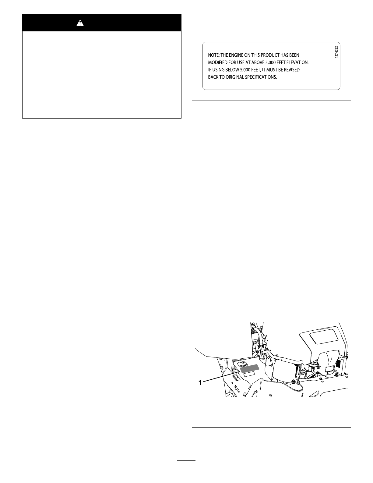
Important:IfyouareusingamachinewithaToro
engineabove1500m(5,000ft)foracontinuous
period,ensurethattheHighAltitudeKithasbeen
installedsothattheenginemeetsCARB/EP A
emissionregulations.TheHighAltitudeKit
increasesengineperformancewhilepreventing
spark-plugfouling,hardstarting,andincreased
emissions.Onceyouhaveinstalledthekit,attach
thehigh-altitudelabelnexttotheserialdecalon
themachine.ContactanyAuthorizedToroService
DealertoobtaintheproperHighAltitudeKitand
high-altitudelabelforyourmachine.Tolocate
adealerconvenienttoyou,accessourwebsite
atwww.T oro.comorcontactourToroCustomer
CareDepartmentatthenumber(s)listedinyour
EmissionControlWarrantyStatement.
Removethekitfromtheengineandrestorethe
enginetoitsoriginalfactorycongurationwhen
runningtheengineunder1500m(5,000ft).Do
notoperateanenginethathasbeenconverted
forhigh-altitudeuseatloweraltitudes;otherwise,
youcouldoverheatanddamagetheengine.
Ifyouareunsurewhetherornotyourmachine
hasbeenconvertedforhigh-altitudeuse,lookfor
thefollowinglabel.
decal127-9363
Introduction
Thisrotary-blade,ridinglawnmowerisintended
tobeusedbyresidentialhomeownersorhired
operators.Itisdesignedprimarilyforcuttinggrasson
well-maintainedlawnsonresidentialorcommercial
properties.Itisnotdesignedforcuttingbrushorfor
agriculturaluses.
Readthisinformationcarefullytolearnhowtooperate
andmaintainyourproductproperlyandtoavoid
injuryandproductdamage.Youareresponsiblefor
operatingtheproductproperlyandsafely .
YoumaycontactT orodirectlyatwww.Toro.com
forproductsafetyandoperationtrainingmaterials,
accessoryinformation,helpndingadealer,orto
registeryourproduct.
Wheneveryouneedservice,genuineToroparts,or
additionalinformation,contactanAuthorizedService
DealerorToroCustomerServiceandhavethemodel
andserialnumbersofyourproductready.Figure1
identiesthelocationofthemodelandserialnumbers
ontheproduct.Writethenumbersinthespace
provided.
g188704
Figure1
1.Modelandserialnumberplate
Writetheproductmodelandserialnumbersinthe
spacebelow:
©2017—TheToro®Company
8111LyndaleAvenueSouth
Bloomington,MN55420
Contactusatwww.Toro.com.
2
PrintedintheUSA
AllRightsReserved
Page 3

ModelNo.
SerialNo.
Thismanualidentiespotentialhazardsandhas
safetymessagesidentiedbythesafety-alertsymbol
(Figure2),whichsignalsahazardthatmaycause
seriousinjuryordeathifyoudonotfollowthe
recommendedprecautions.
Figure2
Safety-AlertSymbol
Thismanualuses2wordstohighlightinformation.
Importantcallsattentiontospecialmechanical
informationandNoteemphasizesgeneralinformation
worthyofspecialattention.
Contents
Safety.......................................................................4
GeneralSafety...................................................4
SlopeIndicator...................................................5
SafetyandInstructionalDecals..........................6
ProductOverview....................................................11
Controls............................................................11
BeforeOperation.................................................13
BeforeOperationSafety...................................13
RecommendedFuel.........................................13
UsingStabilizer/Conditioner.............................14
FillingtheFuelTank..........................................14
CheckingtheEngine-OilLevel..........................14
BreakinginaNewMachine..............................14
ThinkSafetyFirst..............................................15
UsingtheSafety-InterlockSystem....................15
PositioningtheSeat..........................................16
AdjustingtheMyRide™Suspension
System..........................................................17
AdjustingtheMotion-ControlLevers.................18
DuringOperation.................................................18
DuringOperationSafety...................................18
OperatingtheParkingBrake.............................20
OperatingtheMowerBlade-ControlSwitch
(PTO)............................................................20
OperatingtheThrottle.......................................21
OperatingtheChoke.........................................21
OperatingtheIgnitionSwitch............................21
StartingandShuttingOfftheEngine.................22
UsingtheMotion-ControlLevers.......................22
DrivingtheMachine..........................................23
UsingtheSmartSpeed
TM
Control
System..........................................................24
StoppingtheMachine.......................................24
UsingtheSideDischarge.................................25
AdjustingtheHeightofCut...............................26
AdjustingtheAnti-ScalpRollers........................27
UsingAttachmentsandAccessories.................27
OperatingTips.................................................28
AfterOperation....................................................29
AfterOperationSafety......................................29
PushingtheMachinebyHand..........................29
TransportingtheMachine.................................30
LoadingtheMachine........................................30
Maintenance...........................................................32
g000502
RecommendedMaintenanceSchedule(s)...........32
Pre-MaintenanceProcedures..............................33
MaintenanceandStorageSafety......................33
EngineMaintenance...........................................34
EngineSafety...................................................34
ServicingtheAirCleaner..................................34
ServicingtheEngineOil....................................35
ServicingtheSparkPlug...................................37
CleaningtheCoolingSystem............................38
FuelSystemMaintenance...................................39
ReplacingtheIn-LineFuelFilter.......................39
ElectricalSystemMaintenance...........................40
ElectricalSystemSafety...................................40
ServicingtheBattery.........................................40
ServicingtheFuses..........................................42
DriveSystemMaintenance..................................42
CheckingtheTirePressure...............................42
MowerMaintenance.............................................43
ServicingtheCuttingBlades.............................43
LevelingtheMowerDeck..................................46
RemovingtheMowerDeck...............................47
InstallingtheMowerDeck.................................48
ReplacingtheGrassDeector..........................49
MowerBeltMaintenance......................................50
InspectingtheBelts..........................................50
ReplacingtheMowerBelt.................................50
Cleaning..............................................................51
WashingtheUndersideoftheMower................51
CleaningtheSuspensionSystem.....................51
DisposingofWaste...........................................51
Storage...................................................................52
CleaningandStorage.......................................52
Troubleshooting......................................................53
Schematics.............................................................55
3
Page 4

Safety
Thismachinehasbeendesignedinaccordancewith
ANSIB71.1-2012.
GeneralSafety
Thisproductiscapableofamputatinghandsand
feetandofthrowingobjects.Alwaysfollowallsafety
instructionstoavoidseriouspersonalinjury.
Usingthisproductforpurposesotherthanitsintended
usecouldprovedangeroustoyouandbystanders.
•Readandunderstandthecontentsofthis
Operator’sManualbeforeyoustarttheengine.
Ensurethateveryoneusingthisproductknows
howtouseitandunderstandsthewarnings.
•Donotputyourhandsorfeetnearmoving
componentsofthemachine.
•Donotoperatethemachinewithoutallguards
andothersafetyprotectivedevicesinplaceand
workingonthemachine.
•Keepclearofanydischargeopening.Keep
bystandersasafedistanceawayfromthe
machine.
•Keepchildrenoutoftheoperatingarea.Never
allowchildrentooperatethemachine.
•Stopthemachineandshutofftheenginebefore
servicing,fueling,oruncloggingthemachine.
Improperlyusingormaintainingthismachinecan
resultininjury.Toreducethepotentialforinjury,
complywiththesesafetyinstructionsandalwayspay
attentiontothesafety-alertsymbol,whichmeans
Caution,Warning,orDanger—personalsafety
instruction.Failuretocomplywiththeseinstructions
mayresultinpersonalinjuryordeath.
Youcanndadditionalitemsofsafetyinformationin
theirrespectivesectionsthroughoutthismanual.
4
Page 5
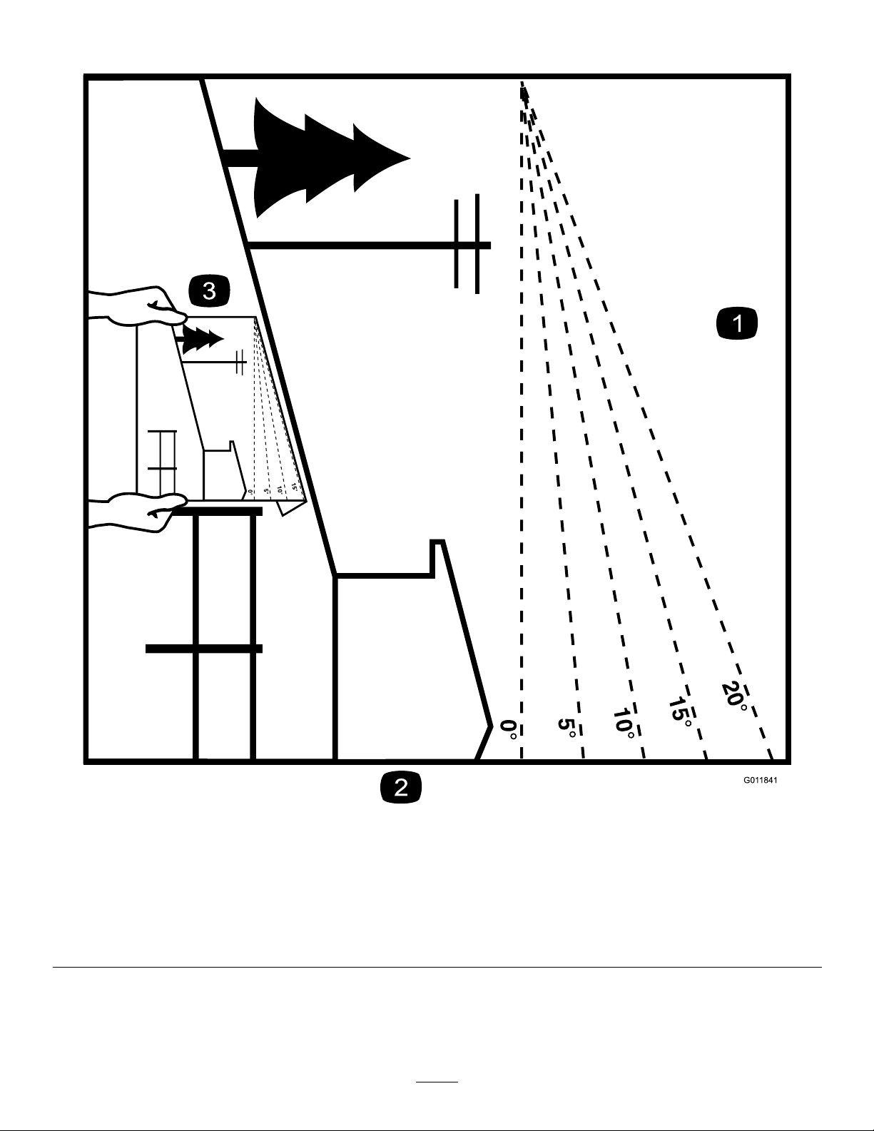
SlopeIndicator
G011841
Figure4
Thispagemaybecopiedforpersonaluse.
1.Themaximumslopeyoucansafelyoperatethemachineonis15degrees.Usetheslopecharttodeterminethedegreeofslope
ofhillsbeforeoperating.Donotoperatethismachineonaslopegreaterthan15degrees.Foldalongtheappropriateline
tomatchtherecommendedslope.
2.Alignthisedgewithaverticalsurface,atree,building,fencepole,etc.
3.Exampleofhowtocompareslopewithfoldededge
5
g011841
Page 6
SafetyandInstructionalDecals
Safetydecalsandinstructionsareeasilyvisibletotheoperatorandarelocatednearanyarea
ofpotentialdanger.Replaceanydecalthatisdamagedormissing.
Manufacturer'sMark
1.Indicatesthebladeisidentiedasapartfromtheoriginal
machinemanufacturer.
decaloemmarkt
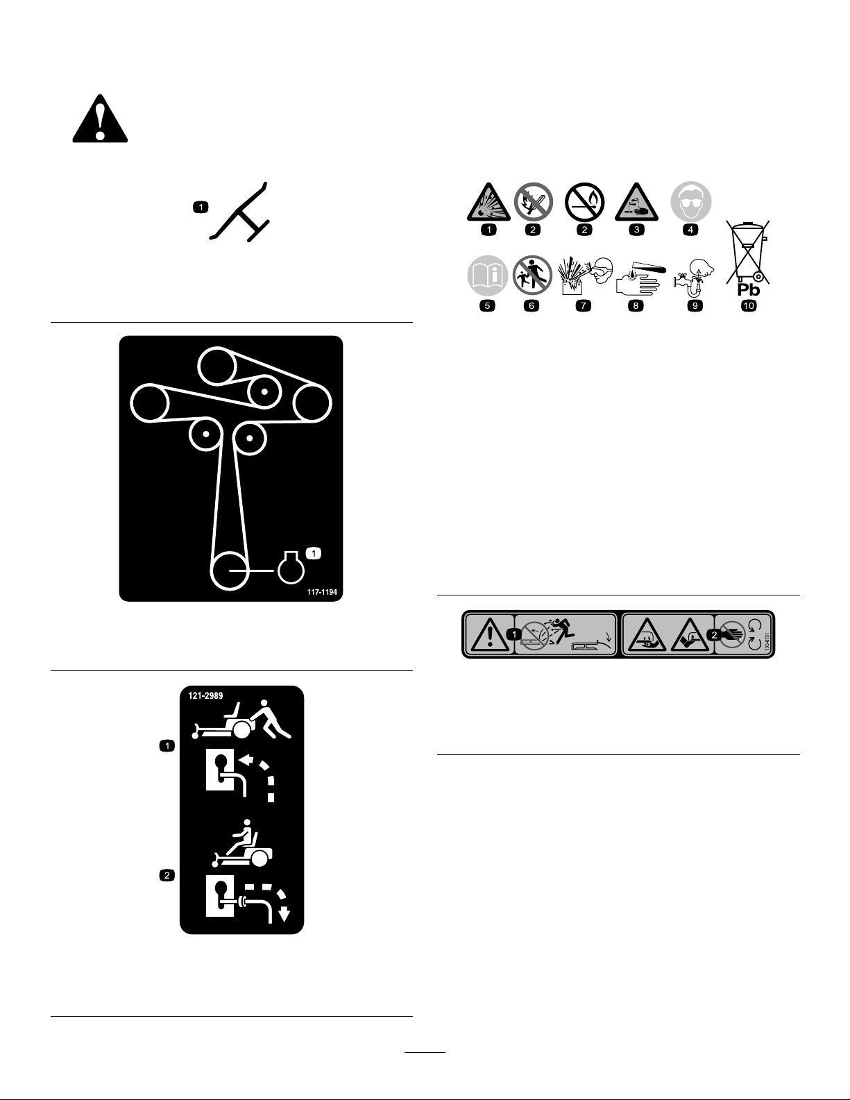
decalbatterysymbols
BatterySymbols
Someorallofthesesymbolsareonyourbattery .
1.Explosionhazard
2.Nore,opename,or
smoking
3.Causticliquid/chemical
burnhazard
4.Weareyeprotection.9.Flusheyesimmediately
5.ReadtheOperator's
Manual.
decal117-1 194
6.Keepbystandersasafe
distanceawayfromthe
battery.
7.Weareyeprotection;
explosivegasescan
causeblindnessandother
injuries.
8.Batteryacidcancause
blindnessorsevereburns.
withwaterandgetmedical
helpfast.
10.Containslead;donot
discard.
117-1194
1.Engine
decal130-0731
130-0731
1.Warning—thrownobject
hazard;keepthedeector
shieldinplace.
2.Cuttinghazardofhandor
foot,mowerblade—keep
awayfrommovingparts.
1.Bypassleverpositionfor
pushingthemachine
decal121-2989b
121-2989
2.Bypassleverpositionfor
operatingthemachine
6
Page 7
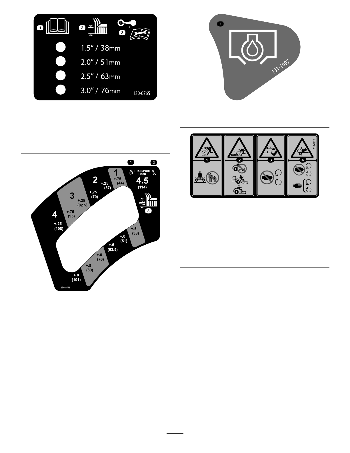
decal130-0765
130-0765
131-1097
decal131-1097
1.ReadtheOperator's
Manual.
2.Height-of-cutselection
3.Removethekeyfrom
theignitionandreadthe
Operator'sManualbefore
performingmaintenance.
1.Oildrain
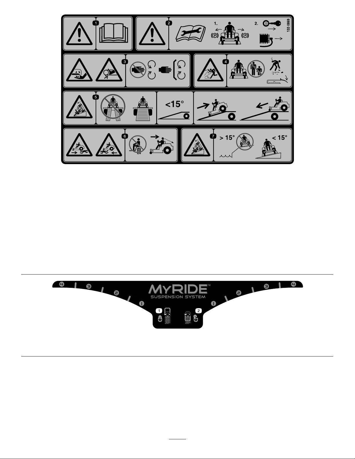
1.Thrownobject
hazard—keepbystanders
awayfromthemachine.
2.Thrownobjecthazard,
raisedbafe—donot
operatethemachinewith
anopendeck;usea
baggerorabafe.
decal132-0872
132-0872
3.Severinghazardofhand
orfoot—keepawayfrom
movingparts.
4.Entanglement
hazard—keepaway
frommovingparts;keep
allguardsandshieldsin
place.
decal130-0654
130-0654
1.Transport—lock
2.Transport—unlock
3.Heightofcut
7
Page 8
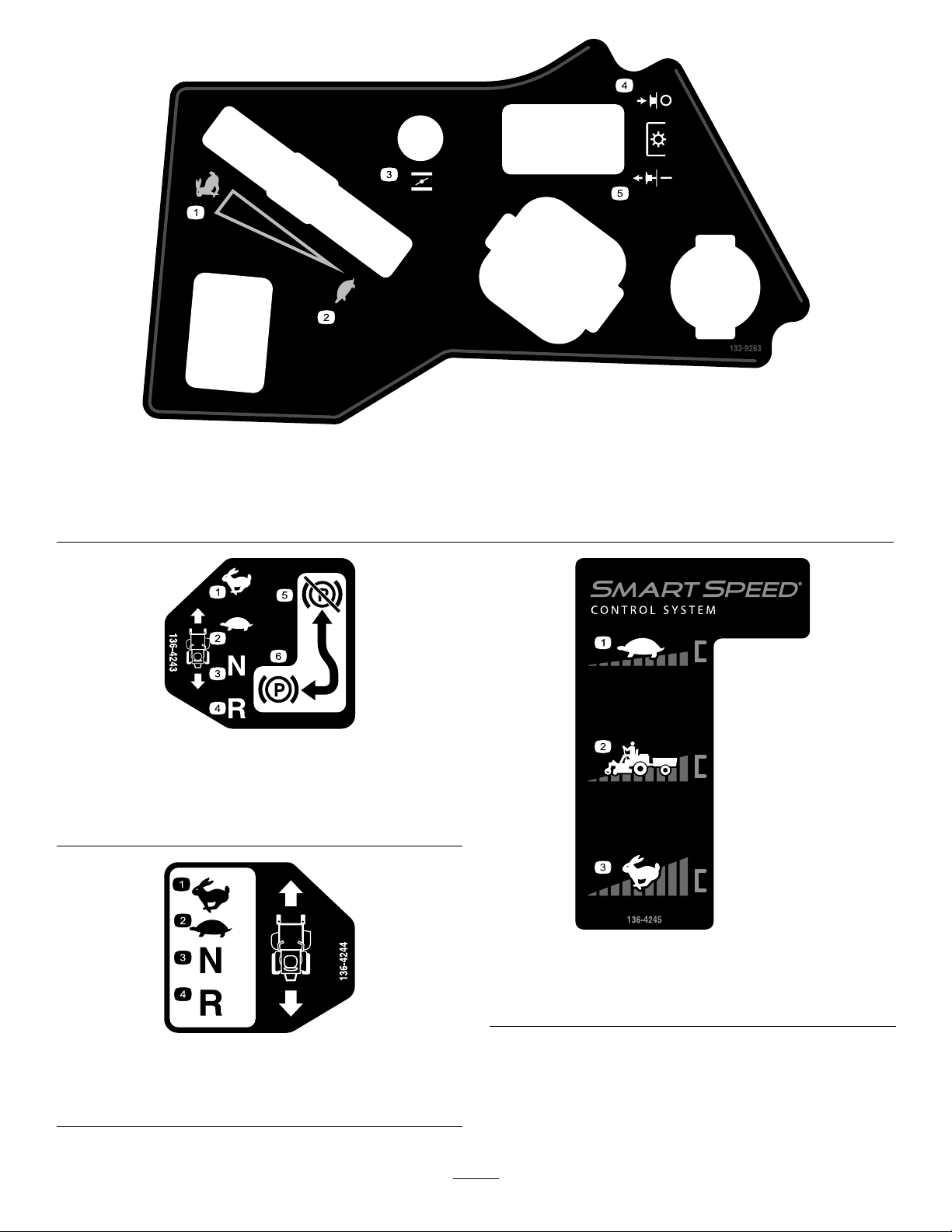
decal132-0869
132-0869
1.Warning—readtheOperator'sManual.
2.Warning—readtheinstructionsbeforeservicingorperforming
5.Ramphazard—Whenloadingontoatrailer,donotusesplit
6.Crushing/dismembermenthazardofbystanders,inreverse
maintenance;movethemotion-controlleverstothepark
(brake)position,removetheignitionkey,anddisconnectthe
spark-plugwire.
3.Cutting/dismembermenthazard,mowerblade;entanglement
7.Tippinghazard—donotusethemachineneardrop-offswith
hazard,belt—stayawayfrommovingpartsandkeepall
guardsandshieldsinplace.
4.Thrownobjecthazard—keepbystandersasafedistance
awayfromthemachine,pickupdebrisbeforeoperating,and
keepthedeectorinplace.
133-5198
1.Camlock2.Camunlock
ramps.Onlyuseafull-widthrampwideenoughforthe
machine.Rampanglewiththegroundshouldbelessthan15
degrees.Backuptherampanddriveforwardofftheramp.
andforward—donotcarrypassengers,lookbehindanddown
whenreversing.
slopesgreaterthan15degreesornearwater;onlyuseon
slopeslessthan15degrees.
decal133-5198
8
Page 9
decal133-9263
133-9263
1.Fast
2.Slow5.PTOengage
3.Choke
decal136-4243
136-4243
1.Fast4.Reverse
2.Slow
3.Neutral6.Parkingbrakeengaged
5.Parkingbrakedisengaged
4.PTOdisengage
136-4244
1.Fast3.Neutral
2.Slow
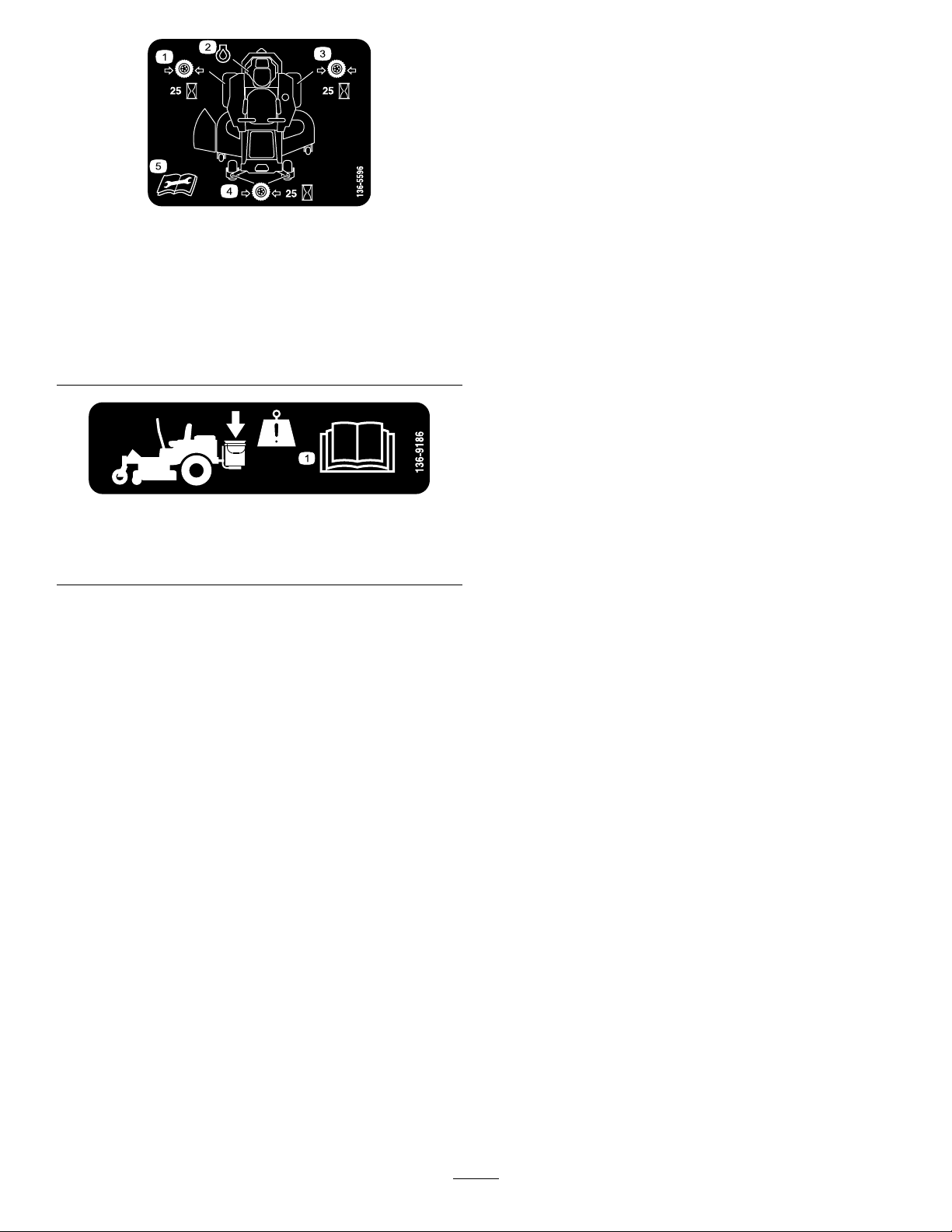
decal136-4245
136-4245
1.Slow
2.Transport
decal136-4244
4.Reverse
3.Fast
9
Page 10
decal136-5596
136-5596
1.Checkthetirepressure
every25operatinghours.
2.Engineoil
4.Checkthetirepressure
every25operatinghours.
5.ReadtheOperator's
Manualbeforeperforming
maintenance.
3.Checkthetirepressure
every25operatinghours.
136-9186
1.ReadtheOperator'sManualbeforeaddingweighttothe
bucket.
decal136-9186
10
Page 11
ProductOverview
Controls
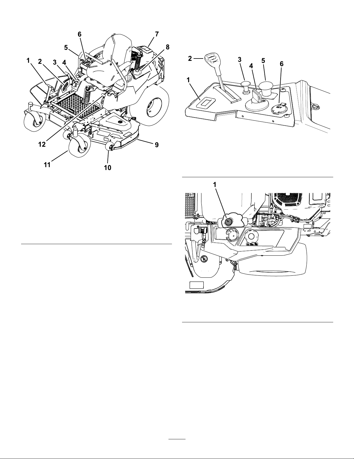
BecomefamiliarwithallcontrolsinFigure6and
Figure7beforeyoustarttheengineandoperatethe
machine.
g188738
Figure6
1.Hourmeter4.Ignitionswitch
2.Throttlecontrol
3.Chokecontrol
g195717
Figure5
5.PTOswitch
6.12Vpowerpoint
1.Deck-liftpedal
2.Height-of-cutpin
3.Height-of-cut
lever/transportlock
4.SmartSpeed™lever
5.Motion-controllever
6.Controls
7.Engine
8.Fuelcap
9.Mowerdeck
10.Anti-scalproller
11.Casterwheel
12.Parking-brakelever
g188776
Figure7
1.Fuelgauge
FuelGauge
Thefuelgaugedisplaystheamountoffuelinthetank
(Figure7).
ThrottleControl
Thethrottlecontrolstheenginespeed,andithasa
continuous-variablesettingfromtheSLOWtoFAST
position(Figure6).
11
Page 12

ChokeControl
12VPowerPoint
Usethechokecontroltostartacoldengine.Pullthe
chokecontroluptoengageit.Pushdownonthe
chokecontroltodisengageit.
HourMeter
Thehourmeterrecordsthenumberofhoursthe
enginehasoperated.Itoperateswhentheengine
isrunning.Usethesetimesforschedulingregular
maintenance(Figure6).
Motion-ControlLevers
Themotion-controlleversarespeed-sensitivecontrols
ofindependentwheelmotors.Movingaleverforward
orbackwardturnsthewheelonthesamesideforward
orinreverse;wheelspeedisproportionaltothe
amounttheleverismoved.Movethecontrollevers
outwardfromthecentertotheNEUTRAL-LOCKposition
andexitthemachine(Figure5).Alwayspositionthe
motion-controlleversintotheNEUTRAL-LOCKposition
whenyoustopthemachineorleaveitunattended.
Parking-BrakeLever
Usethepowerpointtopower12Vaccessories
(Figure6).
Important:Whennotusingthe12Vpowerpoint,
inserttherubberplugtopreventdamagetothe
powerpoint.
IgnitionSwitch
Usethisswitchtostartthemowerengine.Ithas3
positions:ST ART,RUN,andOFF.
Blade-ControlSwitch(Power
Takeoff)
Theblade-controlswitch(PTO)engagesand
disengagespowertothemowerblades(Figure6).
Height-of-CutLever
Theheight-of-cutleverworkswiththefootpedalto
lockthedeckinaspeciccuttingheight.Onlyadjust
theheightofcutwhilemachineisnotmoving(Figure
5).
Theparking-brakeleverislocatedonleftsideof
theconsole(Figure5).Thebrakeleverengagesa
parkingbrakeonthedrivewheels.
Toengagetheparkingbrake,pulluptheleveruntilit
latchesintothedetentslot.
Todisengagetheparkingbrake,pulltheleveroutof
thedetentslotandtowardyou,thenpushitdown.
FootPedalDeck-LiftSystem
Thefootpedaldeck-liftsystemallowsyoutolower
andraisethedeckfromtheseatedposition.Y ou
canusethefootpedaltoliftthedeckbrieytoavoid
obstaclesorlockthedeckinthehighestheightofcut
ortransportposition(Figure5).
SmartSpeed™ControlSystem
Lever
TheSmartSpeed™Control-Systemlever,located
belowtheoperatingposition,givesyouachoiceto
drivethemachineat3speedranges—trim,tow,and
mow(Figure27).
Attachments/Accessories
AselectionofToroapprovedattachmentsand
accessoriesisavailableforusewiththemachineto
enhanceandexpanditscapabilities.Contactyour
AuthorizedServiceDealerorDistributororgoto
www.T oro.comforalistofallapprovedattachments
andaccessories.
12
Page 13

Operation
containersontheground,awayfromyourvehicle
beforelling.
Note:Determinetheleftandrightsidesofthe
machinefromthenormaloperatingposition.
BeforeOperation
BeforeOperationSafety
GeneralSafety
•Neverallowchildrenoruntrainedpeopleto
operateorservicethemachine.Localregulations
mayrestricttheageoftheoperator.Theowner
isresponsiblefortrainingalloperatorsand
mechanics.
•Becomefamiliarwiththesafeoperationofthe
equipment,operatorcontrols,andsafetysigns.
•Knowhowtostopthemachineandshutoffthe
enginequickly.
•Checkthatoperator-presencecontrols,safety
switches,andshieldsareattachedandfunctioning
properly.Donotoperatethemachineunlessthey
arefunctioningproperly.
•Beforemowing,alwaysinspectthemachineto
ensurethattheblades,bladebolts,andcutting
assembliesareingoodworkingcondition.
Replacewornordamagedbladesandboltsinsets
topreservebalance.
•Inspecttheareawhereyouwillusethemachine
andremoveallobjectsthatthemachinecould
throw.
•Evaluatetheterraintodeterminetheappropriate
equipmentandanyattachmentsoraccessories
requiredtooperatethemachineproperlyand
safely.
FuelSafety
•Toavoidpersonalinjuryorpropertydamage,use
extremecareinhandlingfuel.Fuelvaporsare
ammableandexplosive.
•Extinguishallcigarettes,cigars,pipes,andother
sourcesofignition.
•Useonlyanapprovedfuelcontainer.
•Donotremovethefuelcaporaddfueltothefuel
tankwhiletheengineisrunningorwhilehot.
•Donotrefuelthemachineindoors.
•Donotstorethemachineorfuelcontainerwhere
thereisanopename,spark,orpilotlight,such
asonawaterheateroronotherappliances.
•Donotllcontainersinsideavehicleoronatruck
ortrailerbedwithaplasticliner.Alwaysplace
•Removetheequipmentfromthetruckortrailer
andrefuelitwhileitisontheground.Ifthisisnot
possible,thenrefuelfromaportablecontainer
ratherthanafuel-dispensernozzle.
•Donotoperatethemachinewithouttheentire
exhaustsysteminplaceandinproperworking
condition.
•Keepthefuel-dispensernozzleincontactwith
therimofthefueltankorcontaineropeningat
alltimesuntilfuelingiscomplete.Donotusea
nozzlelock-opendevice.
•Ifyouspillfuelonyourclothing,changeyour
clothingimmediately.Wipeupanyfuelthatspills.
•Neveroverllthefueltank.Replacethefuelcap
andtightenitsecurely.
•Storefuelinanapprovedcontainerandkeepit
outofthereachofchildren.Neverbuymorethan
a30-daysupplyoffuel.
•Donotllthefueltankcompletelyfull.Addfuelto
thefueltankuntilthelevelis6to13mm(1/4to
1/2inch)belowthebottomofthellerneck.This
emptyspaceinthetankallowsfueltoexpand.
–Avoidprolongedbreathingofvapors.
–Keepyourfaceawayfromthenozzleandfuel
tankopening.
–Avoidcontactwithskin;washoffspillswith
soapandwater.
RecommendedFuel
•Forbestresults,useonlyclean,fresh(lessthan
30daysold),unleadedgasolinewithanoctane
ratingof87orhigher((R+M)/2ratingmethod).
•Ethanol:Gasolinewithupto10%ethanol
(gasohol)or15%MTBE(methyltertiarybutyl
ether)byvolumeisacceptable.Ethanoland
MTBEarenotthesame.Gasolinewith15%
ethanol(E15)byvolumeisnotapprovedforuse.
Neverusegasolinethatcontainsmorethan
10%ethanolbyvolume,suchasE15(contains
15%ethanol),E20(contains20%ethanol),orE85
(containsupto85%ethanol).Usingunapproved
gasolinemaycauseperformanceproblemsand/or
enginedamagewhichmaynotbecoveredunder
warranty.
•Donotusegasolinecontainingmethanol.
•Donotstorefueleitherinthefueltankorfuel
containersoverthewinterunlessyouuseafuel
stabilizer.
•Donotaddoiltogasoline.
13
Page 14
Using Stabilizer/Conditioner
Useafuelstabilizer/conditionerinthemachineto
providethefollowingbenets:
•Keepsfuelfreshduringstorageof90daysorless
(drainthefueltankwhenstoringthemachinefor
morethan90days)
•Cleanstheenginewhileitruns
•Eliminatesgum-likevarnishbuildupinthefuel
system,whichcauseshardstarting
Important:Donotusefueladditives
containingmethanolorethanol.
Addthecorrectamountoffuelstabilizer/conditioner
tothefuel.
Note:Afuelstabilizer/conditionerismost
effectivewhenmixedwithfreshfuel.T ominimize
thechanceofvarnishdepositsinthefuelsystem,
usefuelstabilizeratalltimes.
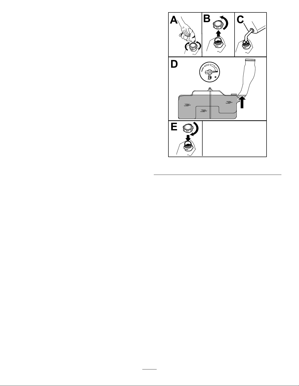
FillingtheFuelTank
1.Parkthemachineonalevelsurface.
2.Engagetheparkingbrake.
3.Shutofftheengineandremovethekey.
4.Cleanaroundthefuel-tankcap.
5.Fillthefueltankuntilthefuelgaugereadsatthe
fullmark(Figure8).
Note:Donotllthefueltankcompletelyfull.
Theemptyspaceinthetankallowsthefuelto
expand.
g197123
Figure8
CheckingtheEngine-Oil Level
Beforeyoustarttheengineandusethemachine,
checktheoillevelintheenginecrankcase;referto
CheckingtheEngine-OilLevel(page14).
BreakinginaNewMachine
Newenginestaketimetodevelopfullpower.Mower
decksanddrivesystemshavehigherfrictionwhen
new,placingadditionalloadontheengine.Allow
40to50hoursofbreak-intimefornewmachinesto
developfullpowerandbestperformance.
14
Page 15
ThinkSafetyFirst
G009027
1
2
CAUTION
Pleasereadallsafetyinstructionsandsymbolsinthe
safetysection.Knowingthisinformationcouldhelp
youorbystandersavoidinjury.
DANGER
Operatingthemachineonwetgrassorsteep
slopescancauseslidingandlossofcontrol.
•Donotoperateonslopesgreaterthan15
degrees.
•Reducespeedanduseextremecautionon
slopes.
•Donotoperatethemachinenearwater.
DANGER
Wheelsdroppingoveredgescancause
rollovers,whichmayresultinseriousinjury,
death,ordrowning.
Donotoperatethemachineneardrop-offs.
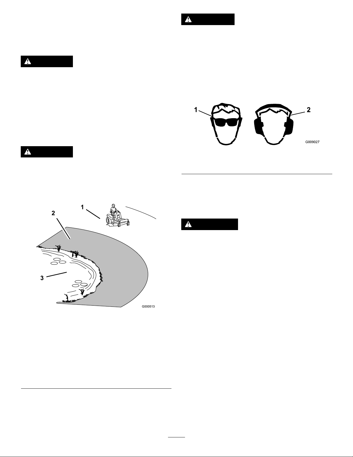
Thismachineproducessoundlevelsin
excessof85dBAattheoperator’searand
cancausehearinglossthroughextended
periodsofexposure.
Wearhearingprotectionwhenoperatingthis
machine.
Useprotectiveequipmentforyoureyes,ears,hands,
feet,andhead.
g009027
Figure10
1.Weareyeprotection.2.Wearhearingprotection.
UsingtheSafety-Interlock
1.SafeZone—usethe
machinehereonslopes
lessthan15degreesor
atareas.
2.DangerZone—usea
walk-behindmowerand/or
ahandtrimmeronslopes
greaterthan15degrees
andneardrop-offsor
water.
Figure9
3.Water
System
WARNING
Ifthesafety-interlockswitchesare
disconnectedordamaged,themachinecould
operateunexpectedly,causingpersonal
injury.
•Donottamperwiththeinterlockswitches.
•Checktheoperationoftheinterlock
switchesdailyandreplaceanydamaged
switchesbeforeoperatingthemachine.
g000513
Understandingthe
Safety-InterlockSystem
Thesafety-interlocksystemisdesignedtopreventthe
enginefromstartingunless:
•Theblade-controlswitch(PTO)isdisengaged.
•Themotion-controlleversareintheNEUTRAL-LOCK
position.
•Theparkingbrakeisengaged.
Thesafety-interlocksystemalsoisdesignedtoshut
offtheenginewheneverthecontrolleversareoutof
theNEUTRAL-LOCKpositionandyourisefromtheseat.
15
Page 16
TestingtheSafety-Interlock
System
ServiceInterval:Beforeeachuseordaily
Testthesafety-interlocksystembeforeyouusethe
machineeachtime.Ifthesafetysystemdoesnot
operateasdescribedbelow,haveanAuthorized
ServiceDealerrepairthesafetysystemimmediately .
1.Sitontheseat,engagetheparkingbrake,and
movetheblade-controlswitch(PTO)totheON
position.Trystartingtheengine;theengine
shouldnotcrank.
2.Sitontheseat,engagetheparkingbrake,and
movetheblade-controlswitch(PTO)totheOFF
position.Moveeithermotion-controllever(out
oftheNEUTRAL-LOCKposition).Trystartingthe
engine;theengineshouldnotcrank.Repeatfor
othercontrollever.
3.Sitontheseat,engagetheparkingbrake,
movetheblade-controlswitch(PTO)totheOFF
position,andmovethemotion-controlleversto
theNEUTRAL-LOCKposition.Starttheengine.
Whiletheengineisrunning,releasetheparking
brake,engagetheblade-controlswitch(PTO),
andriseslightlyfromtheseat;theengineshould
shutoff.
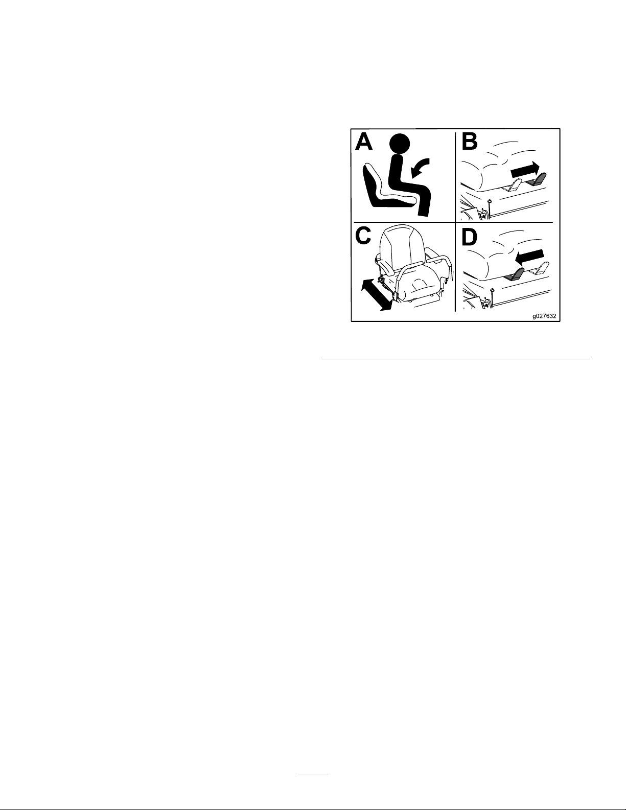
PositioningtheSeat
Theseatmovesforwardandbackward.Positionthe
seatwhereyouhavethebestcontrolofthemachine
andaremostcomfortable.
Toadjust,movetheleversidewaystounlocktheseat
(Figure11).
g027632
Figure11
4.Sitontheseat,engagetheparkingbrake,
movetheblade-controlswitch(PTO)totheOFF
position,andmovethemotion-controllevers
toNEUTRAL-LOCKposition.Starttheengine.
Whiletheengineisrunning,centereither
motion-controlleverandmoveitforwardor
reverse;theengineshouldshutoff.Repeatfor
othermotion-controllever.
5.Sitontheseat,disengagetheparkingbrake,
movetheblade-controlswitch(PTO)totheOFF
position,andmovethemotion-controlleversto
NEUTRAL-LOCKposition.Trystartingtheengine;
theengineshouldnotcrank.
16
Page 17
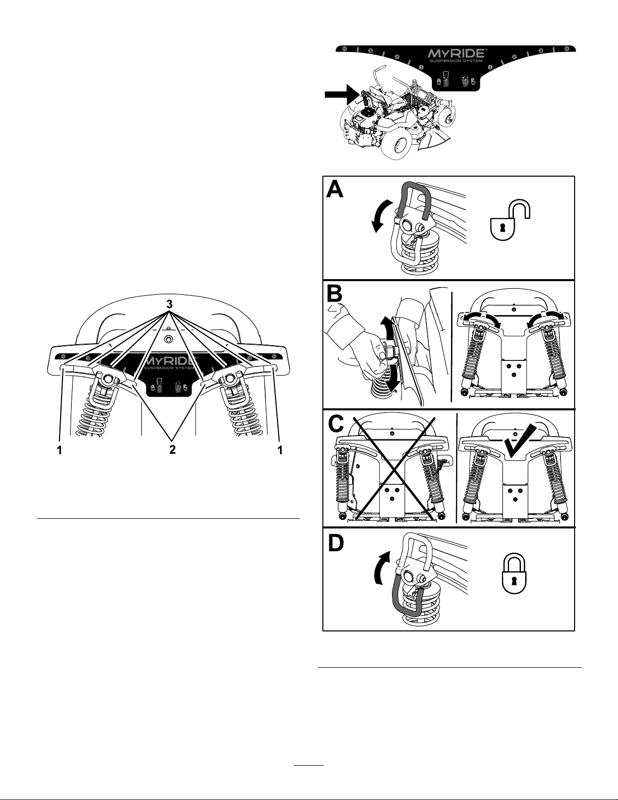
AdjustingtheMyRide™ SuspensionSystem
TheMyRide™suspensionsystemadjuststoprovide
asmoothandcomfortableride.Adjustingtherear
2-shockassembliesistheeasiestandquickest
adjustmentforchangingthesuspensionsystem.
Positionthesuspensionsystemwhereyouaremost
comfortable.
Adjusttherear-shockassemblies(Figure13).
AdjustingtheRear-Shock
Assemblies
Theslotsfortherear-shockassemblieshave
detentpositionsforreference.Youcanpositionthe
rear-shockassembliesanywhereintheslot,notjust
inthedetentpositions.
Thefollowinggraphicshowsthepositionforasoftor
rmrideandthedifferentdetentpositions(Figure12).
g195746
Figure12
1.Firmestposition3.Detentsintheslots
2.Softestposition
Note:Ensurethattheleftandrightrear-shock
assembliesarealwaysadjustedtothesamepositions.
g195744
g195745
Figure13
17
Page 18

g027252
B
A
Adjustingthe Motion-ControlLevers
AdjustingtheHeight
Youcanadjustthemotion-controllevershigheror
lowerformaximumcomfort(Figure14).
Figure14
AdjustingtheTilt
Youcanadjustthemotion-controlleversforwardor
rearwardforyourcomfort.
1.Loosentheupperboltholdingthecontrollever
tothecontrol-armshaft.
2.Loosenthelowerboltjustenoughtopivotthe
controlleverforwardorrearward(Figure14).
3.Tightenbothboltstosecurethecontrolleverin
thenewposition.
4.Repeattheadjustmentfortheothercontrollever.
DuringOperation
DuringOperationSafety
GeneralSafety
•Theowner/operatorcanpreventandisresponsible
foraccidentsthatmaycausepersonalinjuryor
propertydamage.
•Wearappropriateclothing,includingeye
protection;slip-resistant,substantialfootwear;and
hearingprotection.Tiebacklonghairanddonot
wearjewelry.
•Donotoperatethemachinewhileill,tired,or
undertheinuenceofalcoholordrugs.
•Nevercarrypassengersonthemachineandkeep
bystandersandpetsawayfromthemachine
duringoperation.
•Operatethemachineonlyingoodvisibilitytoavoid
g027252
holesorhiddenhazards.
•Avoidmowingonwetgrass.Reducedtraction
couldcausethemachinetoslide.
•Ensurethatalldrivesareinneutral,theparking
brakeisengaged,andyouareintheoperating
positionbeforeyoustarttheengine.
•Keepyourhandsandfeetawayfromthecutting
units.Keepclearofthedischargeopeningatall
times.
•Lookbehindanddownbeforebackinguptobe
sureofaclearpath.
•Usecarewhenapproachingblindcorners,shrubs,
trees,orotherobjectsthatmayobscureyour
vision.
•Donotmowneardrop-offs,ditches,or
embankments.Themachinecouldsuddenlyroll
overifawheelgoesovertheedgeoriftheedge
givesway.
•Stopthebladeswheneveryouarenotmowing.
•Stopthemachineandinspectthebladesafter
strikinganobjectorifthereisanabnormal
vibrationinthemachine.Makeallnecessary
repairsbeforeresumingoperation.
•Slowdownandusecautionwhenmakingturns
andcrossingroadsandsidewalkswiththe
machine.Alwaysyieldtheright-of-way.
•Disengagethedrivetothecuttingunitandshut
offtheenginebeforeadjustingtheheightof
cut(unlessyoucanadjustitfromtheoperating
position).
•Neverrunanengineinanareawhereexhaust
gasesareenclosed.
•Neverleavearunningmachineunattended.
18
Page 19

•Beforeleavingtheoperatingposition(including
toemptythecatchersortounclogthechute),do
thefollowing:
–Stopthemachineonlevelground.
–Disengagethepowertake-offandlowerthe
attachments.
–Engagetheparkingbrake.
–Shutofftheengineandremovethekey.
–Waitforallmovingpartstostop.
•Donotoperatethemachinewhenthereistherisk
oflightning.
•Donotusethemachineasatowingvehicle.
•Donotchangethegovernorspeedoroverspeed
theengine.
•Useaccessoriesandattachmentsapprovedby
Toroonly.
SlopeSafety
•Establishyourownproceduresandrulesfor
operatingonslopes.Theseproceduresmust
includesurveyingthesitetodeterminewhich
slopesaresafeformachineoperation.Always
usecommonsenseandgoodjudgmentwhen
performingthissurvey.
machinecouldsuddenlyrolloverifawheelgoes
overtheedgeortheedgecavesin.Establisha
safetyareabetweenthemachineandanyhazard
(2machinewidths).
•A2-postROPS(RolloverProtectionSystem)is
availableforthemachineasanaccessory.A
ROPSisrecommendedifyouwillbemowingnext
todrop-offs,nearwater,oronsteepbankswhich
couldresultinarollover.ContactanAuthorized
ServiceDealerformoredetails.TheCalifornia
CodeofRegulationsrequiresROPS(ifavailable)
onallmowersusedcommerciallyeffectiveMarch
1,201 1.
•Slopesareamajorfactorrelatedtoloss-of-control
andtip-overaccidents,whichcanresultinsevere
injuryordeath.Operatingthemachineonany
sloperequiresextracaution.
•Operatethemachineatalowerspeedwhenyou
areonaslope.
•Ifyoufeeluneasyoperatingthemachineona
slope,donotdoit.
•Watchforholes,ruts,bumps,rocks,orother
hiddenobjects.Uneventerraincouldoverturnthe
machine.T allgrasscanhideobstacles.
•Choosealowgroundspeedsoyouwillnothave
tostoporshiftwhileonaslope.
•Arollovercanoccurbeforethetireslosetraction.
•Avoidoperatingthemachineonwetgrass.Tires
maylosetraction;regardlessifthebrakesare
availableandfunctioning.
•Avoidstarting,stopping,orturningthemachine
onaslope.
•Keepallmovementonslopesslowandgradual.
Donotsuddenlychangethespeedordirectionof
themachine.
•Donotoperatethemachineneardrop-offs,
ditches,embankments,orbodiesofwater.The
19
Page 20

OperatingtheParking
G008945
G009174
OperatingtheMower
Brake
Alwaysengagetheparkingbrakewhenyoustopthe
machineorleaveitunattended.
EngagingtheParkingBrake
WARNING
Theparkingbrakemaynotholdthemachine
parkedonaslopeandcouldcausepersonal
injuryorpropertydamage.
Donotparkonslopesunlessthewheelsare
chockedorblocked.
Toengagetheparkingbrake,pulluptheparking
brakeuntilitlatchesintothedetentslot(Figure15).
Blade-ControlSwitch(PTO)
Theblade-controlswitch(PTO)startsandstopsthe
mowerbladesandanypoweredattachments.
EngagingtheBlade-Control
Switch(PTO)
g008945
Figure17
Note:Alwaysengagethebladeswiththethrottlein
theFASTposition(Figure18).
Figure15
1.Pulluptheparkingbrake.
DisengagingtheParkingBrake
Todisengagetheparkingbrake,pulltheleveroutof
thedetentslotandtowardyou,thenpushitdown
(Figure16).
Figure16
1.Pushtheparkingbrake
outofthedetentslotand
towardyou.
2.Pushtheparkingbrake
down.
g188778
g187516
Figure18
DisengagingtheBlade-Control
Switch(PTO)
g188777
g009174
Figure19
20
Page 21

OperatingtheThrottle
G008959
1
2
START
RUN
STOP
G008947
OperatingtheIgnition
YoucanmovethethrottlecontrolbetweentheFAST
andSLOWpositions(Figure20).
AlwaysusetheFASTpositionwhenturningonthe
mowerdeckwiththeblade-controlswitch(PTO).
Figure20
OperatingtheChoke
Usethechoketostartacoldengine.
Switch
1.TurntheignitionkeytotheSTARTposition
(Figure22).
Note:Whentheenginesstarts,releasethekey.
Important:Donotengagestarterformore
than5secondsatatime.Iftheenginefails
tostart,allowa15secondcool-downperiod
betweenattempts.Failuretofollowthese
instructionscanburnoutthestartermotor.
Note:Y oumayneedmultipleattemptstostart
theenginewhenyoustartitthersttimeafter
thefuelsystemhasbeenwithoutfuelcompletely.
g187517
1.Iftheengineiscold,usethechoketostartthe
engine.
Figure22
g008947
2.Pulluponthechokeknobtoengagethechoke
beforeusingtheignitionswitch(Figure21).
3.Pushdownonthechoketodisengagethechoke
2.Turntheignitionkeytoshutofftheengine.
aftertheenginehasstarted(Figure21).
g008959
Figure21
1.ONposition2.OFFposition
21
Page 22

StartingandShuttingOff
UsingtheMotion-Control
theEngine
StartingtheEngine
Note:Awarmorhotenginemaynotrequirechoking.
Important:Donotengagethestarterformore
than5secondsatatime.Engagingthestarter
motorformorethan5secondscandamagethe
startermotor.Iftheenginefailstostart,wait10
secondsbeforeoperatingtheenginestarteragain.
Levers
Figure23
ShuttingOfftheEngine
1.Disengagethebladesbymovingthe
blade-controlswitchtotheOFFposition(Figure
21).
g004532
Figure24
1.Motion-control
lever—NEUTRAL-LOCK
position
2.Center,unlockedposition5.Frontofmachine
3.Forward
g189354
4.Backward
2.MovethethrottlelevertotheFASTposition.
3.TurntheignitionkeytotheOFFpositionand
removethekey.
22
Page 23

DrivingtheMachine
G008952
DrivingForward
Thedrivewheelsturnindependently,poweredby
hydraulicmotorsoneachaxle.Youcanturn1side
inreversewhileyouturntheotherforward,causing
themachinetospinratherthanturn.Thisgreatly
improvesthemachinemaneuverabilitybutmay
requiresometimeforyoutoadapttohowitmoves.
Thethrottlecontrolregulatestheenginespeedas
measuredinrpm(revolutionsperminute).Place
thethrottlecontrolintheFASTpositionforbest
performance.Alwaysoperateinthefullthrottle
positionwhenmowing.
CAUTION
Themachinecanspinveryrapidly ,which
maycauseyoutolosecontrolofmachine,
resultinginpersonalinjuryordamageto
machine.
•Usecautionwhenmakingturns.
•Slowthemachinedownbeforemaking
sharpturns.
Note:Theenginestopswhenyoumovethe
traction-controlwiththeparkingbrakeengaged.
Tostop,pullthemotion-controlleverstotheNEUTRAL
position.
1.Disengagetheparkingbrake;referto
DisengagingtheParkingBrake(page20).
2.Movetheleverstothecenter,unlockedposition.
3.T ogoforward,slowlypushthemotion-control
leversforward(Figure25).
Figure25
g008952
23
Page 24

DrivingBackward
G008953
3.Adjustthelevertothedesiredposition.
1.Movetheleverstothecenter,unlockedposition.
2.T ogobackward,slowlypullthemotion-control
leversrearward(Figure26).
Figure26
Thefollowingareonlyrecommendationsforuse.
Adjustmentsvarybygrasstype,moisturecontent,
andtheheightofthegrass.
Suggested
uses:
ParkingX
Heavy,wet
grass
TrainingX
BaggingX
MulchingX
Normal
mowing
TransportX
TrimTowMow
X
X
Trim
Thisisthelowestspeed.Thesuggestedusesforthis
speedareasfollows:
•Parking
g008953
•Heavy,wetgrassmowingconditions
•Training
UsingtheSmartSpeed
ControlSystem
TheSmartSpeed
therightoftheoperatingposition(Figure27),gives
youachoicetodrivethemachineat3groundspeed
ranges—trim,tow,andmow.
1.Smart-speedlever
Tochangespeeds,dothefollowing:
TM
Control-Systemlever,locatedto
Figure27
Tow
TM
Thisisthemediumspeed.Thesuggestedusesfor
thisspeedareasfollows:
•Bagging
•Mulching
Mow
Thisisthefastestspeed.Thesuggestedusesforthis
speedareasfollows:
•Normalmowing
•Transportingthemachine
StoppingtheMachine
Tostopthemachine,movethetraction-controllevers
toneutral,andthenmovethemtothelockedposition,
disengagetheblade-controlswitch(PTO),andturn
g197125
theignitionkeytotheOFFposition.
Engagetheparkingbrakewhenyouleavethe
machine;refertoEngagingtheParkingBrake(page
20).Remembertoremovethekeyfromtheignition
switch.
1.Movethemotion-controlleverstoneutraland
outwardtotheNEUTRAL-LOCKposition.
2.Disengagetheblade-controlswitch.
24
Page 25

CAUTION
UsingtheSideDischarge
Childrenorbystandersmaybeinjuredifthey
moveorattempttooperatethemachinewhile
itisunattended.
Alwaysremovetheignitionkeyandengage
theparkingbrakewhenleavingthemachine
unattended,evenifjustforafewminutes.
Themowerhasahingedgrassdeectorthat
dispersesclippingstothesideanddowntowardthe
turf.
DANGER
Withoutagrassdeector,dischargecover,or
acompletegrass-catcherassemblymounted
inplace,youandothersareexposedtoblade
contactandthrowndebris.Contactwith
rotatingmowerblade(s)andthrowndebris
willcauseinjuryordeath.
•Neverremovethegrassdeectorfrom
themowerbecausethegrassdeector
routesmaterialdowntowardtheturf.Ifthe
grassdeectoriseverdamaged,replaceit
immediately.
•Neverputyourhandsorfeetunderthe
mower.
•Nevertrytoclearthedischargearea
ormowerbladesunlessyoumovethe
blade-controlswitch(PTO)totheOFF
position,rotatetheignitionkeytotheOFF
position,andremovethekey.
•Makesurethatthegrassdeectorisinthe
downposition.
25
Page 26

AdjustingtheHeightofCut
g024409
Themachineisequippedwithafootpedaldeck-lift
system.Youcanusethefootpedaltoliftthedeck
brieytoavoidobstaclesorlockthedeckinthe
highestheightofcutortransportposition.Youcan
usetheheight-of-cutleverwiththefootpedaltolock
thedeckinaspeciccuttingheight.
UsingtheFootPedalDeck-Lift
System
•Pressthedeck-liftpedaldowntoraisethedeck;
continuetopressthepedaluntilthedecklocksin
thetransportposition(Figure28).
•Pushonthedeck-liftpedalwithyourfootandpull
thetransportlockhandlerearwardtodisengage
thetransportlock(Figure28).
3.Selectaholeintheheight-of-cutsystem
correspondingtothedesiredheightofcutand
insertthepin(Figure29).
4.Pushonthedeck-liftpedalwithyourfootand
pullthehandlerearwardtodisengagethe
transportlock(Figure28).
5.Lowerthedeckslowlyuntilthelevermakes
contactwiththepin.
Figure28
TransportLockPosition
AdjustingtheHeightofCut
Youcanadjusttheheightofcutfrom38to114mm
(1-1/2to4-1/2inches)in6mm(1/4inch)increments
byrelocatingtheheight-of-cutpinintodifferenthole
locations.
g188850
Figure29
1.Deck-liftpedal
2.Handle
g024409
3.Pin
4.Height-of-cutpositions
1.Pushonthedeck-liftpedalwithyourfootand
raisethemowerdecktothetransport-lock
position(alsothe114mm(4-1/2inches)cutting
heightposition)asshowninFigure29.
2.T oadjust,removethepinfromtheheight-of-cut
bracket(Figure29).
26
Page 27

AdjustingtheAnti-Scalp
g029955
UsingAttachmentsand
Rollers
Wheneveryouchangetheheight-of-cut,itis
recommendedtoadjusttheheightoftheanti-scalp
rollers.
1.Disengagetheblade-controlswitch(PTO),move
themotion-controlleverstotheNEUTRAL-LOCK
position,andengagetheparkingbrake.
2.Shutofftheengine,removethekey ,andwait
forallmovingpartstostopbeforeleavingthe
operatingposition.
3.Adjusttheanti-scalprollersasshowninFigure
30.
Accessories
UseonlyToroapprovedattachmentsandaccessories.
Ifyouattachabuckettotheengineguard,useanylon
straptosecureit.
Important:Thebucketweightimpactsthe
stabilityofthemachine.Ifyouarecarryingmore
thantheweightlistedinthetablebelowina
bucketattachedtotheengineguard,youmust
equipyourmachinewiththeBucket-SupportKit.
ContactyourauthorizedToroservicedealer.
ModelMaximumweightperbucket
48-inchdeck
54-inchdeck
60-inchdeck
withouttheBucket-Support
Kit
1.1kg(2.5lb)
1.1kg(2.5lb)
4.5kg(10lb)
Figure30
1.Anti-scalproller4.Flangenut
2.Spacer
3.Bushing
5.Bolt
g029955
27
Page 28

OperatingTips
UsingtheFastThrottleSetting
dropontoyourlawn.Toavoidthis,moveontoa
previouslycutareawiththebladesengagedoryou
candisengagethemowerdeckwhilemovingforward.
Forbestmowingandmaximumaircirculation,operate
theengineattheFASTposition.Airisrequiredto
thoroughlycutgrassclippings,sodonotsetthe
height-of-cutsolowastototallysurroundthemower
inuncutgrass.Alwaystrytohave1sideofthemower
freefromuncutgrass,whichallowsairtobedrawn
intothemower.
CuttingaLawnfortheFirstTime
Cutgrassslightlylongerthannormaltoensurethat
thecuttingheightofthemowerdoesnotscalpany
unevenground.However,thecuttingheightusedin
thepastisgenerallythebestonetouse.Whencutting
grasslongerthan15cm(6inches)tall,youmaywant
tocutthelawntwicetoensureanacceptablequality
ofcut.
CuttingaThirdoftheGrassBlade
Itisbesttocutonlyaboutathirdofthegrassblade.
Cuttingmorethanthatisnotrecommendedunless
grassissparse,oritislatefallwhengrassgrows
moreslowly.
KeepingtheUndersideofthe
MowerClean
Cleanclippingsanddirtfromtheundersideofthe
moweraftereachuse.Ifgrassanddirtbuildupinside
themower,cuttingqualitywilleventuallybecome
unsatisfactory.
MaintainingtheBlade(s)
Maintainasharpbladethroughoutthecuttingseason
becauseasharpbladecutscleanlywithouttearingor
shreddingthegrassblades.Tearingandshredding
turnsgrassbrownattheedges,whichslowsgrowth
andincreasesthechanceofdisease.Checkthe
mowerbladesaftereachuseforsharpness,and
foranywearordamage.Filedownanynicksand
sharpenthebladesasnecessary.Ifabladeis
damagedorworn,replaceitimmediatelywitha
genuineT ororeplacementblade.
AlternatingtheMowingDirection
Alternatethemowingdirectiontokeepthegrass
standingstraight.Thisalsohelpsdisperseclippings
whichenhancesdecompositionandfertilization.
MowingatCorrectIntervals
Grassgrowsatdifferentratesatdifferenttimesof
theyear.T omaintainthesamecuttingheight,mow
moreofteninearlyspring.Asthegrassgrowthrate
slowsinmidsummer,mowlessfrequently.Ifyou
cannotmowforanextendedperiod,rstmowata
highcuttingheight,thenmowagain2dayslaterata
lowerheightsetting.
UsingaSlowerCuttingSpeed
Toimprovecutquality,useaslowergroundspeed
incertainconditions.
AvoidingCuttingTooLow
Whenmowinguneventurf,raisethecuttingheight
toavoidscalpingtheturf.
StoppingtheMachine
Ifyoumuststoptheforwardmotionofthemachine
whilemowing,aclumpofgrassclippingsmay
28
Page 29

AfterOperation
PushingtheMachineby Hand
AfterOperationSafety
GeneralSafety
•Cleangrassanddebrisfromthecuttingunits,
mufers,andenginecompartmenttohelpprevent
res.Cleanupoilorfuelspills.
•Shutoffthefuelbeforestoringortransportingthe
machine.
•Disengagethedrivetotheattachmentwhenever
youaretransportingornotusingthemachine.
•Usefull-widthrampsforloadingthemachineinto
atrailerortruck.
•Tiethemachinedownsecurelyusingstraps,
chains,cable,orropes.Bothfrontandrearstraps
shouldbedirecteddownandoutwardfromthe
machine.
•Allowtheenginetocoolbeforestoringthemachine
inanyenclosure.
•Neverstorethemachineorfuelcontainerwhere
thereisanopename,spark,orpilotlight,such
asonawaterheateroronotherappliances.
Important:Alwayspushthemachinebyhand.Do
nottowthemachine,becausedamagemayoccur.
Thismachinehasanelectric-brakemechanism,and
topushthemachine,theignitionkeymustbeinthe
RUNposition.Thebatteryneedstobechargedand
functioningfortheelectricbraketobedisengaged.
PushingtheMachine
1.Parkthemachineonalevelsurface,and
disengagetheblade-controlswitch.
2.Engagetheparkingbrake,shutofftheengine,
andwaitforallmovingpartstostopbefore
leavingtheoperatingposition.
3.Locatethebypassleversontheframeonboth
sidesoftheengine.
4.Movethebypassleversforwardthroughthekey
holeanddowntolocktheminplace(Figure31).
Note:Dothisforeachlever.
5.Disengagetheparkingbrake.
Note:Donotstartthemachine.
1.Bypasslever
2.Leverpositionforpushing
29
g188854
Figure31
3.Leverpositionfor
operatingthemachine
themachine
Page 30

OperatingtheMachine
LoadingtheMachine
Movethebypassleversrearwardthroughthekeyhole
anddowntolocktheminplaceasshowninFigure31.
Note:Dothisforeachlever.
TransportingtheMachine
Useaheavy-dutytrailerortrucktotransportthe
machine.Ensurethatthetrailerortruckhasall
necessarybrakes,lighting,andmarkingasrequired
bylaw.Pleasecarefullyreadallthesafetyinstructions.
Knowingthisinformationcouldhelpyou,yourfamily,
pets,orbystandersavoidinjury.
WARNING
Drivingonthestreetorroadwaywithout
turnsignals,lights,reectivemarkings,ora
slow-moving-vehicleemblemisdangerous
andcanleadtoaccidents,causingpersonal
injury.
Donotdrivethemachineonapublicstreet
orroadway.
1.Ifyouareusingatrailer,connectittothetowing
vehicleandconnectthesafetychains.
2.Ifapplicable,connectthetrailerbrakes.
Useextremecautionwhenloadingorunloading
machinesontoatraileroratruck.Useafull-width
rampthatiswiderthanthemachineforthisprocedure.
Backthemachineuptherampanddriveitforward
downtheramp(Figure33).
Figure33
1.Backthemachineupthe
ramp.
2.Drivethemachineforward
downtheramp.
Important:Donotusenarrowindividualramps
foreachsideofthemachine.
WARNING
Loadingamachineontoatrailerortruck
increasesthepossibilityoftip-overandcould
causeseriousinjuryordeath(Figure34).
•Useextremecautionwhenoperatinga
machineonaramp.
g027995
3.Loadthemachineontothetrailerortruck.
4.Shutofftheengine,removethekey,setthe
brake,andclosethefuelvalve.
5.Tiedownthemachinenearthefrontcaster
wheelsandtherearbumper(Figure32).
Figure32
•Useonlyafull-widthramp;donotuse
individualrampsforeachsideofthe
machine.
•Donotexceeda15-degreeanglebetween
therampandthegroundorbetweenthe
rampandthetrailerortruck.
•Ensurethatthelengthoframpisatleast
4timesaslongastheheightofthetrailer
ortruckbedtotheground.Thisensures
thattherampangledoesnotexceed15
degreesonatground.
•Backuprampsanddriveforwarddown
ramps.
g027708
•Avoidsuddenaccelerationordeceleration
whiledrivingthemachineonarampas
thiscouldcausealossofcontrolora
tip-oversituation.
30
Page 31

g027996
5
1
2
6
Figure34
g027996
1.Full-widthrampinstowed
position
2.Sideviewoffull-width
rampinloadingposition
3.Notgreaterthan
15degrees
4.Rampisatleast4times
aslongastheheightof
thetrailerortruckbedto
theground
5.H=heightofthetraileror
truckbedtotheground
6.Trailer
31
Page 32

Maintenance
Note:Determinetheleftandrightsidesofthemachinefromthenormaloperatingposition.
RecommendedMaintenanceSchedule(s)
MaintenanceService
Interval
Aftertherst5hours
Beforeeachuseordaily
Aftereachuse
Every25hours
Every100hours
Every200hours
MaintenanceProcedure
•Changetheengineoil.
•Checkthesafety-interlocksystem.
•Checktheaircleanerfordirty,loose,ordamagedparts.
•Checktheengine-oillevel.
•Cleantheairintakescreen.
•Inspecttheblades.
•Inspectthegrassdeectorfordamage.
•Cleanthemower-deckhousing.
•Cleantheair-cleanerfoamelement(moreoftenindusty ,dirtyconditions).
•Checktirepressure.
•Checkthebeltsforwearorcracks.
•Replacetheair-cleanerfoamelement(moreoftenindusty,dirtyconditions).
•Servicetheair-cleanerpaperelement(moreoftenindusty,dirtyconditions).
•Changetheengineoil(moreoftenindusty,dirtyconditions).
•Changetheoillter(moreoftenindusty,dirtyconditions).
•Checkthesparkplug(s).
•Checkthein-linefuellter.
•Replacetheair-cleanerpaperelement(moreoftenindusty,dirtyconditions).
•Replacethesparkplug(s).
•Replacethein-linefuellter.
•Chargethebatteryanddisconnectthebatterycables.
Beforestorage
•Performallmaintenanceprocedureslistedabovebeforestorage.
•Paintanychippedsurfaces.
CAUTION
Ifyouleavethekeyintheignitionswitch,someonecouldaccidentlystarttheengineand
seriouslyinjureyouorotherbystanders.
Removethekeyfromtheignitionbeforeyouperformanymaintenance.
32
Page 33

Pre-Maintenance
othermanufacturerscouldbedangerous,and
suchusecouldvoidtheproductwarranty.
Procedures
MaintenanceandStorage Safety
•Beforerepairingthemachinedothefollowing:
–Disengagethedrives.
–Engagetheparkingbrake.
–Shutofftheengineandremovethekey.
–Disconnectthespark-plugwire.
•Parkthemachineonalevelsurface.
•Cleangrassanddebrisfromthecuttingunit,
drives,mufers,andenginetohelppreventres.
•Cleanupoilorfuelspills.
•Lettheenginecoolbeforestoringthemachine.
•Donotstorethemachineorfuelnearamesor
drainthefuelindoors.
•Donotallowuntrainedpersonneltoservicethe
machine.
•Checktheparkingbrakeoperationfrequently.
Adjustandserviceasrequired.
•Usejackstandstosupportthemachineand/or
componentswhenrequired.
•Carefullyreleasepressurefromcomponentswith
storedenergy.
•Disconnectthebatteryorremovethespark-plug
wirebeforemakinganyrepairs.Disconnectthe
negativeterminalrstandthepositiveterminal
last.Connectthepositiveterminalrstand
negativelast.
•Usecarewhencheckingtheblades.Wrapthe
blade(s)orwearthicklypaddedgloves,anduse
cautionwhenservicingthem.Onlyreplaceblades;
donotstraightenorweldthem.
•Keepyourhandsandfeetawayfrommoving
parts.Ifpossible,donotmakeadjustmentswith
theenginerunning.
•Keepallpartsingoodworkingcondition
andallhardwaretightened,especiallythe
blade-attachmentbolts.Replaceallwornor
damageddecals.
•Neverinterferewiththeintendedfunctionofa
safetydeviceorreducetheprotectionprovided
byasafetydevice.Checktheirproperoperation
regularly.
•Toensureoptimumperformanceandcontinued
safetycerticationofthemachine,useonly
genuineT ororeplacementpartsandaccessories.
Replacementpartsandaccessoriesmadeby
33
Page 34

EngineMaintenance
g027800
g027801
g027802
WARNING
Contactwithhotsurfacesmaycausepersonal
injury.
Keepyourhands,feet,face,clothing,and
otherbodypartsawaythemuferandother
hotsurfaces.
EngineSafety
Shutofftheenginebeforecheckingtheoiloradding
oiltothecrankcase.
ServicingtheAirCleaner
ServiceInterval:Beforeeachuseordaily
Note:Servicetheaircleanermorefrequently(every
fewhours)ifoperatingconditionsareextremelydusty
orsandy.
g027800
RemovingtheElements
1.Parkthemachineonalevelsurfaceand
disengagetheblade-controlswitch(PTO).
2.Engagetheparkingbrake,shutofftheengine,
removethekey,andwaitforallmovingpartsto
stopbeforeleavingtheoperatingposition.
3.Cleanaroundtheair-cleanercovertoprevent
dirtfromgettingintotheengineandcausing
damage.
4.Liftthecoverandrotatetheair-cleanerassembly
outoftheengine(Figure35).
g027801
Figure35
5.Removethefoamelementfromthepaper
element(Figure36).
g027802
Figure36
ServicingtheFoamElement
ServiceInterval:Every25hours/Monthly(whichever
comesrst)—Cleantheair-cleaner
foamelement(moreoftenindusty,
dirtyconditions).
Every100hours/Y early(whichevercomes
rst)—Replacetheair-cleanerfoamelement
(moreoftenindusty,dirtyconditions).
Washthefoamelementwithwaterandreplacethe
foamelementifitisdamaged.
34
Page 35

ServicingthePaperElement
SAE 5W -30, 10W -30
SAE 30
SYNTHETIC 5W -20, 5W -30, 10W -30
g029683
ServiceInterval:Every100hours/Yearly(whichever
comesrst)—Servicetheair-cleaner
paperelement(moreoftenindusty,
dirtyconditions).
Every200hours/Every2years(whichever
comesrst)—Replacetheair-cleanerpaper
element(moreoftenindusty,dirtyconditions).
1.Lightlytaptheelementonaatsurfaceto
removedustanddirt.
2.Inspecttheelementfortears,anoilylm,and
damagetotheseal.
Important:Donotcleanthepaperelement
withpressurizedairorliquids,suchas
solvent,gasoline,orkerosene.Replacethe
paperelementifitisdamagedorcannotbe
cleanedthoroughly.
ServicingtheEngineOil
OilType:Detergentoil(APIserviceSF,SG,SH,SJ,
orSL)
Important:Ifyouoverllorunderlltheengine
crankcasewithoilandruntheengine,youmay
damagetheengine.
1.Parkthemachineonalevelsurface,disengage
theblade-controlswitch,shutofftheengine,
engageparkingbrake,andremovethekey.
2.Makesurethattheengineisshutoff,level,and
iscool,sothattheoilhashadtimetodraininto
thesump.
3.T okeepdirt,grassclippings,etc.,outofthe
engine,cleantheareaaroundtheoil-llcapand
dipstickbeforeremovingit(Figure38).
4.Shutofftheengine,removethekey ,andwait
forallmovingpartstostopbeforeleavingthe
operatingposition.
CrankcaseCapacity:withlter—2.4L(2.5USqt)
Viscosity:Seethetablebelow.
Figure37
CheckingtheEngine-OilLevel
ServiceInterval:Beforeeachuseordaily
Note:Checktheoilwhentheengineiscold.
WARNING
g029683
g193541
Figure38
Contactwithhotsurfacesmaycausepersonal
injury.
Keepyourhands,feet,face,clothing,and
otherbodypartsawaythemuferandother
hotsurfaces.
35
Page 36

ChangingtheEngineOilandOil
g027799
A
B
C
D
E
F
G
H
g029570
Filter
ServiceInterval:Aftertherst5hours/Afterthe
rstmonth(whichevercomes
rst)—Changetheengineoil.
Every100hours/Y early(whichevercomes
rst)—Changetheengineoil(moreoftenin
dusty,dirtyconditions).
Every100hours/Y early(whichevercomes
rst)—Changetheoillter(moreoftenindusty,
dirtyconditions).
Note:Changetheengine-oilltermorefrequently
whenoperatingconditionsareextremelydustyor
sandy.
Note:Disposeoftheusedoilatarecyclingcenter.
1.Parkthemachineonalevelsurfacetoensure
thattheoildrainscompletely.
2.DisengagethePTOandensurethattheparking
brakeisengaged.
3.Shutofftheengine,removethekey ,andwait
forallmovingpartstostopbeforeleavingthe
operatingposition.
4.Draintheengineoil.
g027799
g029570
Figure39
36
Page 37

5.Changetheengine-oillter(Figure40).
B
A
C D
E
F
3/4
g027477
Note:Ensurethattheoil-ltergaskettouches
theengineandthenturnthelteranextra3/4
turn.
g193530
Figure41
6.Slowlypourapproximately80%ofthespecied
oilintothellertubeandslowlyaddthe
additionaloiltobringittotheFullmark(Figure
41).
Figure40
ServicingtheSparkPlug
ServiceInterval:Every100hours/Yearly(whichever
comesrst)—Checkthespark
plug(s).
g027477
Every200hours/Every2years(whichever
comesrst)—Replacethesparkplug(s).
Makesurethattheairgapbetweenthecenterand
sideelectrodesiscorrectbeforeinstallingthespark
plug.Useaspark-plugwrenchforremovingand
installingthesparkplug(s)andagappingtool/feeler
gaugetocheckandadjusttheairgap.Installanew
sparkplug(s)ifnecessary.
Type:Champion
Airgap:0.76mm(0.03inch)
®
RN9YCorNGK
®
BPR6ES
RemovingtheSparkPlug
1.DisengagethePTOandensurethattheparking
brakeisengaged.
2.Shutofftheengine,removethekey ,andwait
forallmovingpartstostopbeforeleavingthe
operatingposition.
37
Page 38

B
A
g027478
Figure42
B
A
g027479
B
A
25-30 N-m
18.5-22.1 ft-lb
g027960
C
D
Note:Duetothedeeprecessaroundthespark
plug,blowingoutthecavitywithcompressedair
isthemosteffectivemethodforcleaning.The
sparkplugismostaccessiblewhentheblower
housingisremovedforcleaning.
CheckingtheSparkPlug
InstallingtheSparkPlug
Tightenthesparkplug(s)to25to30N∙m(18.5to
22.1ft-lb).
g027478
Important:Donotcleanthesparkplug(s).
Alwaysreplacethesparkplug(s)whenithas:a
blackcoating,wornelectrodes,anoilylm,or
cracks.
Ifyouseelightbrownorgrayontheinsulator,the
engineisoperatingproperly.Ablackcoatingonthe
insulatorusuallymeanstheaircleanerisdirty .
Setthegapto0.76mm(0.03inch).
Figure43
g027960
Figure44
CleaningtheCooling System
Cleantheairintakescreenfromgrassanddebris
beforeeachuse.
1.Disengagetheblade-controlswitchandapply
theparkingbrake.
2.Shutofftheengine,removethekey ,andwait
forallmovingpartstostopbeforeleavingthe
operatingposition.
g027479
3.Removetheairlterfromtheengine.
4.Removetheengineshroud.
5.T opreventdebrisenteringtheairintake,install
theairltertothelterbase.
6.Cleandebrisandgrassfromtheparts.
7.Removetheairlterandinstalltheengine
shroud.
8.Installtheairlter.
38
Page 39

FuelSystem
g027939
Maintenance
DANGER
Incertainconditions,fuelisextremely
ammableandhighlyexplosive.Areor
explosionfromfuelcanburnyou,others,and
candamageproperty.
•Performanyfuel-relatedmaintenance
whentheengineiscold.Dothisoutdoors
inanopenarea.Wipeupanyfuelthat
spills.
•Neversmokewhendrainingfuel,andstay
awayfromanopenameorwhereaspark
mayignitethefuelfumes.
ReplacingtheIn-LineFuel Filter
g027939
ServiceInterval:Every100hours/Yearly(whichever
comesrst)—Checkthein-linefuel
lter.
Every200hours/Every2years(whichever
comesrst)—Replacethein-linefuellter.
Neverinstalladirtylterifitisremovedfromthefuel
line.
1.Parkthemachineonalevelsurfaceand
disengagetheblade-controlswitch.
2.Ensurethatthebrakeisengaged,shutoffthe
engine,removethekey,andwaitforallmoving
partstostopbeforeleavingtheoperating
position.
g033082
Figure45
39
Page 40

ElectricalSystem
Maintenance
ElectricalSystemSafety
•Disconnectthebatterybeforerepairingthe
machine.Disconnectthenegativeterminalrst
andthepositivelast.Connectthepositiveterminal
rstandthenegativelast.
•Chargethebatteryinanopen,well-ventilated
area,awayfromsparksandames.Unplugthe
chargerbeforeconnectingordisconnectingthe
battery.Wearprotectiveclothinganduseinsulated
tools.
g190587
Figure46
1.Batterycover2.Fasteners
WARNING
CALIFORNIA
Proposition65Warning
Batteryposts,terminals,andrelated
accessoriescontainleadandlead
compounds,chemicalsknownto
theStateofCaliforniatocause
cancerandreproductiveharm.Wash
handsafterhandling.
ServicingtheBattery
RemovingtheBattery
WARNING
Batteryterminalsormetaltoolscouldshort
againstmetalmachinecomponentscausing
sparks.Sparkscancausethebatterygasses
toexplode,resultinginpersonalinjury.
•Whenremovingorinstallingthebattery,
donotallowthebatteryterminalstotouch
anymetalpartsofthemachine.
•Donotallowmetaltoolstoshortbetween
thebatteryterminalsandmetalpartsofthe
machine.
4.Disconnectthenegative(black)groundcable
fromthebatterypost(Figure47).
Note:Retainallfasteners.
WARNING
Incorrectbattery-cableroutingcould
damagethemachineandcablescausing
sparks.Sparkscancausethebattery
gassestoexplode,resultinginpersonal
injury.
•Alwaysdisconnectthenegative
(black)batterycablebefore
disconnectingthepositive(red)
cable.
•Alwaysconnectthepositive(red)
batterycablebeforeconnectingthe
negative(black)cable.
5.Slidetherubbercoverupthepositive(red)
cable.
6.Disconnectthepositive(red)cablefromthe
batterypost(Figure47).
Note:Retainallfasteners.
7.Removethebatteryhold-down(Figure47),and
liftthebatteryfromthebatterytray.
1.Parkthemachineonalevelsurfaceand
disengagetheblade-controlswitch.
2.Ensurethattheparkingbrakeisengaged,
shutofftheengine,removethekey ,andwait
forallmovingpartstostopbeforeleavingthe
operatingposition.
3.Loosenthe2fastenersonthebatterycover
counterclockwise1/4turn,andremovethe
batterycover(Figure46).
40
Page 41

Figure47
1.Battery
2.Negative(–)batterypost
3.Bolt,washer ,andnutfor
thenegative(–)battery
post
4.Bolt,washer ,andnutfor
thepositive(+)battery
post
5.Positive(+)batterypost
6.Terminalboot
7.Batteryhold-down
ChargingtheBattery
ServiceInterval:Beforestorage—Chargethebattery
anddisconnectthebatterycables.
1.Removethebatteryfromthechassis;referto
RemovingtheBattery(page40).
g000538
Figure48
1.Positive(+)batterypost3.Red(+)chargerlead
2.Negative(–)batterypost4.Black(–)chargerlead
g188903
InstallingtheBattery
1.Positionthebatteryinthetray(Figure47).
2.Usingthefastenerspreviouslyremoved,install
thepositive(red)batterycabletothepositive
(+)batteryterminal.
3.Usingthefastenerspreviouslyremoved,install
thenegativebatterycabletothenegative(-)
batteryterminal.
4.Slidetheredterminalbootontothepositive
(red)batterypost.
5.Securethebatterywiththehold-down(Figure
47).
6.Installthebatterycoverbypushingdownand
tighteningthe2fastenersclockwise(Figure46).
2.Chargethebatteryforaminimumof1hourat
6to10A.
Note:Donotoverchargethebattery .
3.Whenthebatteryisfullycharged,unplug
thechargerfromtheelectricaloutlet,then
disconnectthechargerleadsfromthebattery
posts(Figure48).
41
Page 42

ServicingtheFuses
DriveSystem
Theelectricalsystemisprotectedbyfuses.Itrequires
nomaintenance;however,ifafuseblows,checkthe
component/circuitforamalfunctionorshort.
Fusetype:
•Main—F1(15A,blade-type)
•ChargeCircuit—F2(25A,blade-type)
ToreplacetheMain(15A)fuse,reachintothe
openinginthesideoftheconsole,pulloutthefuse,
andinstallanew15Afuse(Figure49).
Figure49
Maintenance
CheckingtheTirePressure
ServiceInterval:Every25hours—Checktire
pressure.
Maintaintheairpressureinthefrontandreartiresas
specied.Uneventirepressurecancauseuneven
cut.Checkthepressureatthevalvestem(Figure51).
Checkthetireswhentheyarecoldtogetthemost
accuratepressurereading.
Refertothemaximumpressuresuggestedbythetire
manufactureronthesidewallofthecasterwheeltires.
Inatethefrontcasterwheeltiresto103kPa(15psi).
Inatethereardrivewheeltiresto90kPa(13psi).
g190588
1.Main(15A)2.Consoleopening
ToreplacetheChargeCircuit(25A)fuse,locatethe
fusetotheleftofbattery,pulloutthefuse,andinstall
anew25Afuse(Figure50).
Figure50
1.Chargecircuit(25A)
g000554
Figure51
1.Valvestem
g190589
42
Page 43

MowerMaintenance
G014972
1
2
3
ServicingtheCutting Blades
Toensureasuperiorqualityofcut,keeptheblades
sharp.Forconvenientsharpeningandreplacement,
keepextrabladesonhand.
g006530
Figure52
BladeSafety
Awornordamagedbladecanbreak,andapieceof
thebladecouldbethrowntowardyouorbystanders,
resultinginseriouspersonalinjuryordeath.Tryingto
repairadamagedblademayresultindiscontinued
safetycerticationoftheproduct.
•Inspectthebladesperiodicallyforwearordamage.
•Usecarewhencheckingtheblades.Wrapthe
bladesorweargloves,andusecautionwhen
servicingtheblades.Onlyreplaceorsharpenthe
blades;neverstraightenorweldthem.
•Onmulti-bladedmachines,takecareasrotating1
bladecancauseotherbladestorotate.
BeforeInspectingorServicingthe
Blades
1.Parkthemachineonalevelsurface,disengage
theblade-controlswitch(PTO),andengagethe
parkingbrake.
2.Shutofftheengine,removethekey,and
disconnectthespark-plugwiresfromthespark
plugs.
1.Cuttingedge3.Wear/slotforming
2.Curvedarea4.Crack
CheckingforBentBlades
Note:Themachinemustbeonalevelsurfacefor
thefollowingprocedure.
1.Raisethemowerdecktothehighest
height-of-cutposition.
2.Whilewearingthicklypaddedgloves,orother
adequatehandprotection,slowlyrotatethe
bladetobemeasureintoapositionthatallows
effectivemeasurementofthedistancebetween
thecuttingedgeandthelevelsurfacethe
machineison(Figure53).
InspectingtheBlades
ServiceInterval:Beforeeachuseordaily
1.Inspectthecuttingedges(Figure52).
2.Iftheedgesarenotsharporhavenicks,remove
andsharpentheblade;refertoSharpeningthe
Blades(page45).
3.Inspecttheblades,especiallyinthecurvedarea.
4.Ifyounoticeanycracks,wear,oraslotforming
inthisarea,immediatelyinstallanewblade
(Figure52).
g014972
Figure53
1.Deck3.Blade
2.Spindlehousing
3.Measurefromthetipofthebladetotheat
surface(Figure54).
43
Page 44

G014973
1
2
3
Figure54
G014974
1
2
3
G014973
1
2
3
g014973
g014973
Figure56
1.Blade(inpositionformeasuring)
2.Levelsurface
3.Measureddistancebetweenbladeandthesurface(A)
4.Rotatethesameblade180degreessothat
theopposingcuttingedgeisnowinthesame
position(Figure55).
Figure55
1.Blade(sidepreviouslymeasured)
2.Measurement(positionusedpreviously)
3.Opposingsideofbladebeingmovedintomeasurement
position
1.Oppositebladeedge(inpositionformeasuring)
2.Levelsurface
3.Secondmeasureddistancebetweenbladeandsurface(B)
A.IfthedifferencebetweenAandBisgreater
than3mm(1/8inch),replacethebladewith
anewblade;refertoRemovingtheBlades
(page45)andInstallingtheBlades(page
45).
Note:Ifabentbladeisreplacedwitha
newblade,andthedimensionobtained
continuestoexceed3mm(1/8inch),the
bladespindlecouldbebent.Contactan
AuthorizedT oroDealerforservice.
B.Ifthevarianceiswithinconstraints,moveto
thenextblade.
g014974
6.Repeatthisprocedureoneachblade.
5.Measurefromthetipofthebladetotheat
surface(Figure56).
Note:Thevarianceshouldbenomorethan
3mm(1/8inch).
44
Page 45

RemovingtheBlades
1
2
3
4
G010341
Thebladesmustbereplacedifasolidobjectishit,if
thebladeisoutofbalance,orifthebladeisbent.For
bestperformanceandcontinuedsafetyconformance
ofthemachine,usegenuineTororeplacementblades.
Replacementbladesmadebyothermanufacturers
mayresultinnon-conformancewithsafetystandards.
1.Holdthebladeendusingaragorthicklypadded
glove.
2.Removethebladebolt,curvedwasher,and
bladefromthespindleshaft(Figure57).
Note:Ifthebladestaysinahorizontalposition,
thebladeisbalancedandcanbeused.
Note:Ifthebladeisnotbalanced,lesome
metalofftheendofthesailareaonly(Figure58).
g000553
Figure59
1.Blade2.Balancer
3.Repeatthisprocedureuntilthebladeis
balanced.
InstallingtheBlades
1.Installthebladeontothespindleshaft(Figure
57).
Important:Thecurvedpartoftheblade
mustbepointingupwardtowardtheinside
ofthemowertoensurepropercutting.
Figure57
1.Sailareaoftheblade3.Curvedwasher
2.Blade4.Bladebolt
SharpeningtheBlades
1.Usealetosharpenthecuttingedgeatboth
endsoftheblade(Figure58).
Note:Maintaintheoriginalangle.
Note:Thebladeretainsitsbalanceifthesame
amountofmaterialisremovedfrombothcutting
edges.
2.Installthecurvedwasher(cuppedsidetoward
theblade)andthebladebolt(Figure57).
3.T orquethebladeboltto135to150N∙m(100
to110ft-lb).
g010341
g004536
Figure60
1.Sailareaoftheblade3.Curvedwasher
g000552
Figure58
1.Sharpenatoriginalangle.
2.Checkthebalanceofthebladebyputtingitona
bladebalancer(Figure59).
2.Blade4.Bladebolt
45
Page 46

LevelingtheMowerDeck
Ensurethatthemowerdeckislevelanytimeyou
installthemowerdeckorwhenyouseeanuneven
cutonyourlawn.
Checkthemowerdeckforbentbladespriorto
leveling;removeandreplaceanybentblades;referto
CheckingforBentBlades(page43)beforecontinuing.
Levelthemowerdeckside-to-sidebeforeadjusting
thefront-to-rearslope.
Requirements:
•Themachinemustbeonalevelsurface.
•All4tiresmustbeproperlyinated;referto
CheckingtheTirePressure(page42).
CheckingtheFront-to-RearBlade
Slope
Checkthefront-to-rearbladelevelanytimeyouinstall
themower.Ifthefrontofthemowerismorethan
7.9mm(5/16inch)lowerthantherearofthemower,
adjustthebladelevelusingthefollowinginstructions:
1.Parkthemachineonalevelsurfaceand
disengagetheblade-controlswitch.
2.Movethemotion-controlleversoutwardtothe
NEUTRAL-LOCKposition,engagetheparking
brake,shutofftheengine,removethekey ,and
waitforallmovingpartstostopbeforeleaving
theoperatingposition.
3.Carefullyrotatethebladessotheyarefacing
fronttorear(Figure62).
CheckingtheSide-to-SideLevel
Themowerbladesmustbelevelfromsidetoside.
Checktheside-to-sidelevelanytimeyouinstallthe
mowerorwhenyouseeanunevencutonyourlawn.
1.Parkthemachineonalevelsurfaceand
disengagetheblade-controlswitch.
2.Movethemotion-controlleversoutwardtothe
NEUTRAL-LOCKposition,shutofftheengine,
removethekey,engagetheparkingbrake,and
waitforallmovingpartstostopbeforeleaving
theoperatingposition.
3.Carefullyrotatethebladessidetoside.
4.Measurebetweentheoutsidecuttingedgesand
theatsurface(Figure61).
Note:Ifbothmeasurementsarenotwithin5
mm(3/16inch),anadjustmentisrequired;refer
toLevelingtheMowerDeck(page47).
4.Measurefromthetipofthefrontbladetothe
atsurfaceandthetipoftherearbladetothe
atsurface(Figure62).
Note:Ifthefrontbladetipisnot1.6to7.9mm
(1/16to5/16inch)lowerthantherearbladetip,
continuetotheLevelingtheMowerDeck(page
47)procedure.
g007199
Figure62
1.Bladesfronttorear3.Measurefromthetipofthe
bladetotheatsurface
here.
2.Outsidecuttingedges
1.Bladessidetoside
2.Outsidecuttingedges
g007202
Figure61
3.Measurefromthetipofthe
bladetotheatsurface
here.
46
Page 47

LevelingtheMowerDeck
1.Settheanti-scalprollerstothetopholesor
removethemcompletelyforthisprocedure;refer
toAdjustingtheAnti-ScalpRollers(page27).
2.Settheheight-of-cutlevertothe76mm(3inch)
position;refertoAdjustingtheHeightofCut
(page26).
3.Place2blockseachhavingathicknessof6.6
cm(2-5/8inches)undereachsideofthefront
edgeofthedeck,butnotundertheanti-scalp
rollerbrackets(Figure63).
4.Place2blockseachhavingathicknessof7.3
cm(2-7/8inches)undertherearedgeofthe
cuttingdeckskirt;1oneachsideofthecutting
deck(Figure63).
g024313
Figure64
Figure63
1.Woodblock—6.6cm
(2-5/8inches)thick
2.Woodblock—7.3cm
(2-7/8inches)thick
3.Frontedge
5.Loosentheadjustmentboltsonall4cornersso
thatthedeckissittingsecurelyonall4blocks
(Figure64).
1.Deck-liftarm
2.Chain
3.Hook
4.Adjustmentbolt
6.Ensurethatthereistensiononall4chains
(Figure64).
7.Tightenthe4adjustmentbolts(Figure64).
8.Ensurethattheblockstsnuglyunderthedeck
g024428
skirtandthatallboltsaretight.
9.Verifythatthedeckislevelbycheckingthe
side-to-sidelevelandfront-to-rearbladeslope;
repeatthedecklevelingprocedureifnecessary.
RemovingtheMowerDeck
Parkthemachineonalevelsurface,disengagethe
blade-controlswitch,movethemotion-controllevers
outwardtotheNEUTRAL-LOCKposition,engagethe
parkingbrake,shutofftheengine,removethekey,
andwaitforallmovingpartstostopbeforeleavingthe
operatingposition.
Lowerthemowertothelowestheightofcut.Select1
ofthefollowingproceduresdependingonthemower
decksizeinstalledtocompletetheremoval.
PreparingtoRemovetheMower
Deck
1.Lowerthemowertothe76mm(3inches)
height-of-cutposition.
2.Removethemowerbeltfromtheenginepulley;
refertoReplacingtheMowerBelt(page50).
47
Page 48

RemovingtheMowerDeck
1.Removethehairpincotterandwashersecuring
thelinkpintotheframeanddeck,andremove
thelinkbar(Figure65).
Figure65
1.Linkpin3.Hairpincotter
2.Washer
InstallingtheMowerDeck
1.Parkthemachineonalevelsurfaceand
disengagetheblade-controlswitch.
2.Movethemotion-controlleversoutwardtothe
NEUTRAL-LOCKposition,shutofftheengine,
removethekey,engagetheparkingbrake,and
waitforallmovingpartstostopbeforeleaving
theoperatingposition.
3.Slidethemowerunderthemachine.
4.Lowertheheight-of-cutlevertothelowest
position.
5.Placetheheight-of-cutpininthelockposition
g028276
forlowestheightofcut.
6.Lifttherearofthemowerdeckandattachthe
chainstotherearliftarms(Figure66).
7.Attachthefrontchainstothefrontliftarms
(Figure66).
2.Liftupthemowerdecktorelievetensionfrom
themowerdeck.
3.Removethechainsfromthehooksonthe
deck-liftarms(Figure66).
Figure66
8.Installthelonglinkbarthroughtheframehanger
anddeck.
9.Securethelinkpinwiththehairpincottersand
washersremovedpreviously(Figure65).
10.Installthemowerbeltontotheenginepulley;
refertoReplacingtheMowerBelt(page50).
g024313
1.Deck-liftarm
2.Chain
3.Hook
4.Adjustmentbolt
4.Raisetheheightofcuttothetransportposition.
5.Removethebeltfromtheclutchpulleyonthe
engine.
6.Slidethemoweroutfromunderneaththe
machine.
Note:Retainallpartsforfutureinstallation.
48
Page 49

ReplacingtheGrass
g017618
1
3
4
2
Deector
ServiceInterval:Beforeeachuseordaily—Inspect
thegrassdeectorfordamage.
WARNING
Anuncovereddischargeopeningcouldallow
thelawnmowertothrowobjectsatyouor
bystandersandresultinseriousinjury.Also,
contactwiththebladecouldoccur.
Neveroperatethelawnmowerunlessyou
installamulchplate,dischargedeector,or
grasscollectionsystem.
Inspectthegrassdeectorfordamagebeforeeach
use.Replaceanydamagedpartsbeforeuse.
1.Disengagethespringfromthenotchinthe
deectorbracketandslidetherodoutofthe
weldeddeckbrackets,spring,anddischarge
deector(Figure67).
4.Installthespringontothestraightendoftherod.
5.Positionthespringontherodasshowninso
theshorterspringendiscomingfromunderthe
rodbeforethebendandgoingovertherodasit
returnsfromthebend.
6.Lifttheloopendofthespringandplaceitinto
thenotchonthedeectorbracket(Figure68).
Figure67
1.Rod4.Deckbrackets
2.Deector5.Springinstalledoverthe
3.Spring
2.Removethedamagedorworndischarge
deector.
rod
g017618
Figure68
1.Rodandspringassembly
installed
2.Loopendofthespring
installedintothenotchin
thedeectorbracket
3.Rod(shortend)moved
behindmowerbracket
4.Shortend,retainedby
mowerbracket.
7.Securetherodandspringassemblybytwisting
itsotheshortendoftherodisplacedbehind
thefrontbracketweldedtothedeck(Figure68).
Important:Thegrassdeectormustbe
springloadedinthedownposition.Liftthe
g197127
deectoruptotestthatitsnapstothefull
downposition.
3.Positionthenewdischargedeectorwiththe
bracketendsbetweentheweldedbracketson
thedeckasshowninFigure68.
49
Page 50

MowerBeltMaintenance
InspectingtheBelts
ServiceInterval:Every25hours—Checkthebelts
forwearorcracks.
Checkthebeltsforcracks,frayededges,burnmarks,
oranyotherdamage.Replacedamagedbelts.
ReplacingtheMowerBelt
Squealingwhenthebeltisrotating,bladesslipping
whencuttinggrass,frayedbeltedges,burnmarks,
andcracksaresignsofawornmowerbelt.Replace
themowerbeltifanyoftheseconditionsareevident.
1.Disengagetheblade-controlswitch(PTO),move
themotion-controlleverstotheNEUTRAL-LOCK
position,andengagetheparkingbrake.
2.Shutofftheengine,removethekey ,andwait
forallmovingpartstostopbeforeleavingthe
operatingposition.
3.Lowerthemowertothe76mm(3inches)
height-of-cutposition.
4.Foreachofthebeltcovers,loosenthe2bolts,
butdonotremovethem.
5.Slidethecoveruntilitisclearoftheboltsandlift
itupandouttoremoveit.
6.Removetheoorpantoaccesstheidlerpulley.
Figure69
1.Spring-removaltool(T oro
PartNo.92-5771)
2.Idlerspring5.Mowerbelt
3.Deckpost
8.Lowerthemowertothelowestheightofcutand
placetheheight-of-cutpininthelockpositionfor
thelowestheight-of-cut.
9.Removethebeltfromthemower-deckpulleys
andremovetheexistingbelt.
10.Installthenewbeltaroundthemowerpulleys
andtheclutchpulleyundertheengine(Figure
69).
4.Idlerarm
g028279
7.Usingaspringremovaltool,(T oroPartNo.
92-5771),removetheidlerspringfromthe
deckposttoremovetensionontheidlerpulley
(Figure69).
WARNING
Thespringisundertensionwhen
installedandcancausepersonalinjury .
Becarefulwhenremovingthebelt.
11.Usingaspring-removaltool,(T oroPartNo.
92-5771),installtheidlerspringoverthedeck
postandplacingtensionontheidlerpulleyand
mowerbelt(Figure69).
12.Ensurethatthebeltisproperlyseatedinall
pulleys.
13.T oinstallthebeltcovers,insertthetabsonthe
eachcoverintothecorrespondingslotsonthe
deckbracket,ensuringthattheyseat.
14.Rotatethecovertothedeckandslidethe
notchesundertheloosenedboltsuntiltheyare
seated.
15.Tightentheboltstosecurethecovertothedeck.
50
Page 51

Cleaning
G017966
2
3
4
5
1
WashingtheUndersideof theMower
ServiceInterval:Aftereachuse—Cleanthe
mower-deckhousing.
Important:Youcanwashthemachinewithamild
detergentandwater.Donotpressurewashthe
machine.Avoidexcessiveuseofwater,especially
nearthecontrolpanel,undertheseat,aroundthe
engine,hydraulicpumps,andmotors.
Washtheundersideofthemoweraftereachuseto
preventgrassbuildupforimprovedmulchactionand
clippingdispersal.
1.Parkthemachineonalevelsurfaceand
disengagetheblade-controlswitch.
2.Movethemotion-controlleversoutwardtothe
NEUTRAL-LOCKposition,engagetheparking
brake,shutofftheengine,removethekey ,and
waitforallmovingpartstostopbeforeleaving
theoperatingposition.
3.Attachthehosecouplingtotheendofthe
mowerwashouttting,andturnthewateron
high(Figure70).
Note:Spreadpetroleumjellyonthewashout
ttingO-ringtomakethecouplingslideon
easierandprotecttheO-ring.
4.Lowerthemowertothelowestheightofcut.
5.Sitontheseatandstarttheengine.
6.Engagetheblade-controlswitchandletthe
mowerrunfor1to3minutes.
7.Disengagetheblade-controlswitch,shutoffthe
engine,removetheignitionkey,andwaitforall
movingpartstostop.
8.Turnthewateroffandremovethecouplingfrom
thewashouttting.
Note:Ifthemowerisnotcleanafter1washing,
soakitandletitstandfor30minutes.Then,
repeattheprocess.
9.Runthemoweragainfor1to3minutesto
removeexcesswater.
WARNING
Abrokenormissingwashouttting
couldexposeyouandotherstothrown
objectsorbladecontact.Contactwitha
bladeorthrowndebriscancauseinjury
ordeath.
•Replacebrokenormissingwashout
ttingimmediately,beforeusing
moweragain.
•Neverputyourhandsorfeetunder
themowerorthroughopeningsinthe
mower.
1.Washoutttinglocations
on54-inchdecks
2.Washoutttinglocations
on48-inchdecks
3.Washouttting
CleaningtheSuspension System
Note:Donotcleantheshockassemblieswith
pressurizedwater(Figure71).
g195820
Figure71
Figure70
g017966
4.O-ring
5.Hose
DisposingofWaste
Engineoil,batteries,hydraulicuid,andengine
coolantarepollutantstotheenvironment.Disposeof
theseaccordingtoyourstateandlocalregulations.
51
Page 52

Storage
CleaningandStorage
1.Disengagetheblade-controlswitch(PTO),
engagetheparkingbrake,turntheignitionkey
totheOFFposition,andremovethekey.
2.Removegrassclippings,dirt,andgrimefromthe
externalpartsoftheentiremachine,especially
theengineandhydraulicsystem.Cleandirtand
chafffromtheoutsideoftheenginecylinder
headnsandblowerhousing.
Important:Youcanwashthemachinewith
milddetergentandwater.Donotpressure
washthemachine.Avoidexcessiveuse
ofwater,especiallynearthecontrolpanel,
engine,hydraulicpumps,andmotors.
3.Checktheparkingbrakeoperation;referto
OperatingtheParkingBrake(page20).
4.Servicetheaircleaner;refertoServicingtheAir
Cleaner(page34).
D.Starttheengineandrunituntilitshutsoff.
E.Disposeoffuelproperly.Recyclethefuel
accordingtolocalcodes.
Important:Donotstore
stabilizer/conditionedfuelover
90days.
11.Checkandtightenallbolts,nuts,andscrews.
Repairorreplaceanypartthatisdamaged.
12.Paintallscratchedorbaremetalsurfaces.Paint
isavailablefromyourAuthorizedServiceDealer.
13.Storethemachineinaclean,drygarageor
storagearea.Removethekeyfromtheignition
switchandkeepitoutofreachofchildrenor
otherunauthorizedusers.Coverthemachineto
protectitandkeepitclean.
5.Changethecrankcaseoil;refertoServicingthe
EngineOil(page35).
6.Checkthetirepressure;refertoCheckingthe
TirePressure(page42).
7.Chargethebattery;refertoChargingtheBattery
(page41).
8.Scrapeanyheavybuildupofgrassanddirt
fromtheundersideofthemower,thenwashthe
mowerwithagardenhose.
Note:Runthemachinewiththeblade-control
switch(PTO)engagedandtheengineathigh
idlefor2to5minutesafterwashing.
9.Checktheconditionoftheblades;referto
ServicingtheCuttingBlades(page43).
10.Preparethemachineforstoragewhennon-use
occursover30days.Preparethemachinefor
storageasfollows:
A.Addapetroleumbased
stabilizer/conditionertofuelinthe
tank.Followmixinginstructionsfrom
thestabilizermanufacturer.Donotuse
analcoholbasedstabilizer(ethanolor
methanol).
Note:Afuelstabilizer/conditionerismost
effectivewhenmixedwithfreshfueland
usedatalltimes.
B.Runtheenginetodistributeconditionedfuel
throughthefuelsystem(5minutes).
C.Shutofftheengine,allowittocool,and
drainthefueltank.
52
Page 53

Troubleshooting
Problem
Thefueltankisshowingsignsof
collapsingorthemachineisshowingsigns
offrequentlyrunningoutoffuel.
Theengineoverheats.
Thestarterdoesnotcrank.
Theenginedoesnotstart,startshard,or
failstokeeprunning.
PossibleCauseCorrectiveAction
1.Theair-cleanerpaperelementclogged.
1.Theengineloadisexcessive.1.Reducegroundspeed.
2.Theoillevelinthecrankcaseislow.2.Addoiltothecrankcase.
3.Thecoolingnsandairpassages
undertheengineblowerhousingare
plugged.
4.Theaircleanerisdirty.
5.Dirt,water,orstalefuelisinfuel
system.
1.Themotion-controlleversarenotin
theNEUTRAL-LOCKposition.
2.Theparkingbrakeisdisengaged.2.Engagetheparkingbrake.
3.Thebatteryisdead.
4.Theelectricalconnectionsare
corrodedorloose.
5.Afuseisblown.5.Replacethefuse.
6.Arelayorswitchisdamaged.
1.Thefueltankisempty.1.Fillthefueltank.
2.Thechokeisnoton.
3.Theaircleanerisdirty.
4.Thespark-plugwire(s)islooseor
disconnected.
5.Thesparkplug(s)ispitted,fouled,or
thegapisincorrect.
6.Thereisdirtinfuellter.6.Replacethefuellter.
7.Dirt,water,orstalefuelisinfuel
system.
8.Thereisincorrectfuelinthefueltank.8.Drainthetankandreplacethefuelwith
9.Theoillevelinthecrankcaseislow.9.Addoiltothecrankcase.
1.Cleanthepaperelement.
3.Removetheobstructionfromthe
coolingnsandairpassages.
4.Cleanorreplacetheair-cleaner
element.
5.ContactanAuthorizedServiceDealer
1.Movethemotion-controlleverstothe
NEUTRAL-LOCKposition.
3.Chargethebattery.
4.Checktheelectricalconnectionsfor
goodcontact.
6.ContactanAuthorizedServiceDealer.
2.MovethechokelevertoOn.
3.Cleanorreplacetheair-cleaner
element.
4.Installthewire(s)onthesparkplug.
5.Installanew,correctlygappedspark
plug(s).
7.ContactanAuthorizedServiceDealer.
thepropertype.
Theenginelosespower.
1.Theengineloadisexcessive.1.Reducegroundspeed.
2.Theaircleanerisdirty.
3.Theoillevelinthecrankcaseislow.3.Addoiltothecrankcase.
4.Thecoolingnsandairpassages
undertheengineblowerhousingare
plugged.
5.Thesparkplug(s)ispitted,fouled,or
thegapisincorrect.
6.Thefueltankventisblocked.6.ContactanAuthorizedServiceDealer.
7.Thereisdirtinthefuellter.7.Replacethefuellter.
8.Dirt,water,orstalefuelisinthefuel
system.
9.Thereisincorrectfuelinthefueltank.9.Drainthetankandreplacethefuelwith
2.Cleantheair-cleanerelement.
4.Removetheobstructionfromthe
coolingnsandairpassages.
5.Installanew,correctlygappedspark
plug(s).
8.ContactanAuthorizedServiceDealer.
thepropertype.
53
Page 54

Problem
PossibleCauseCorrectiveAction
Themachinedoesnotdrive.
Thereisanabnormalvibration.
Thecuttingheightisuneven.
Thebladesdonotrotate.
1.Thebypassvalvesareopen.
2.Thetractionbeltsareworn,loose,or
broken.
3.Thetractionbeltsareoffofthepulleys.3.ContactanAuthorizedServiceDealer.
4.Thetransmissionhasfailed.4.ContactanAuthorizedServiceDealer.
1.Theengine-mountingboltsareloose.1.Tightentheengine-mountingbolts.
2.Theenginepulley ,idlerpulley,orblade
pulleyisloose.
3.Theenginepulleyisdamaged.
4.Thecuttingblade(s)is/arebentor
unbalanced.
5.Ablade-mountingboltisloose.5.Tightentheblade-mountingbolt.
6.Abladespindleisbent.
1.Theblade(s)isnotsharp.1.Sharpentheblade(s).
2.Acuttingblade(s)is/arebent.2.Installanewcuttingblade(s).
3.Themowerisnotlevel.
4.Ananti-scalpwheelisnotsetcorrectly.4.Adjusttheanti-scalpwheelheight.
5.Theundersideofthemowerisdirty.5.Cleantheundersideofthemower.
6.Thetirepressureisincorrect.6.Adjustthetirepressure.
7.Abladespindleisbent.
1.Thedrivebeltisworn,looseorbroken.1.Installanewdrivebelt.
2.Thedrivebeltisoffofthepulley .
3.Thepower-takeoff(PTO)switchor
PTOclutchisfaulty.
4.Themowerbeltisworn,loose,or
broken.
1.Closethetowvalves.
2.ContactanAuthorizedServiceDealer.
2.Tightentheappropriatepulley.
3.ContactanAuthorizedServiceDealer.
4.Installanewcuttingblade(s).
6.ContactanAuthorizedServiceDealer.
3.Levelthemowerfromside-to-sideand
front-to-rear.
7.ContactanAuthorizedServiceDealer.
2.Installthedrivebeltandcheckthe
adjustingshaftsandbeltguidesforthe
correctposition.
3.ContactanAuthorizedServiceDealer.
4.Installanewmowerbelt.
54
Page 55

Schematics
ElectricalDiagram(Rev .A)
55
g203461
Page 56

LimitedWarranty(seewarrantyperiodsbelow)
TheToroWarranty
TimeCutter
ConditionsandProductsCovered
TheT oroCompanyanditsafliate,T oroWarrantyCompany,pursuanttoan
agreementbetweenthem,jointlypromisetorepairtheToroProductslisted
belowifdefectiveinmaterialsorworkmanship.
Thefollowingtimeperiodsapplyfromtheoriginaldateofpurchase:
Products
TimeCutterMowers
•Engines
TimeCutterMowersCommercialuse30days
•Engines
TimeCutterHDMowers
•Engines
CommercialUse
AllMowers
•Attachments1year
•Battery90daysPartsandLabor
•BeltsandTires90days
1
SomeenginesusedonT oroProductsarewarrantedbytheenginemanufacturer.
2
Residentialusemeansuseoftheproductonthesamelotasyourhome.Useatmorethanone
locationisconsideredcommercialuseandthecommercialusewarrantywouldapply.
3
Whicheveroccursrst.
Warrantymaybedeniedifthehourmeterisdisconnected,altered,or
showssignsofbeingtamperedwith.
1
—ResidentialuseKawasaki–3years
1
—Commercialuse
1
—Residentialand
WarrantyPeriod
ResidentialUse
Kohler–3years
Toro–3years
Kawasaki–3years
Kohler–90days
ToroSingleCylinder–90days
ToroTwinCylinder–3years/300
3
Hours
3yearsor300Hours
3yearsor300Hours
1yearPartsonly
2
–3years
3
3
OwnerResponsibilities
YoumustmaintainyourT oroProductbyfollowingthemaintenance
proceduresdescribedintheOperator'sManual.Suchroutinemaintenance,
whetherperformedbyadealerorbyyou,isatyourexpense.
InstructionsforObtainingWarrantyService
IfyouthinkthatyourT oroProductcontainsadefectinmaterialsor
workmanship,followthisprocedure:
1.ContactanyAuthorizedT oroServiceDealertoarrangeserviceat
theirdealership.Tolocateadealerconvenienttoyou,accessourweb
siteatwww .T oro.com.Youmayalsocallthenumberslistedinitem#3
tousethe24-hourT oroDealerlocatorsystem.
2.Bringtheproductandyourproofofpurchase(salesreceipt)tothe
ServiceDealer.Thedealerwilldiagnosetheproblemanddetermineif
itiscoveredunderwarranty.
3.IfforanyreasonyouaredissatisedwiththeServiceDealer’s
analysisorwiththeassistanceprovided,contactusat:
ToroWarrantyCompany
CustomerCareDepartment,RLCDivision
811 1LyndaleAvenueSouth
Bloomington,MN55420-1196
Tollfreeat866-216-6029(U.S.customers)
Tollfreeat866-216-6030(Canadiancustomers)
ItemsandConditionsNotCovered
Thereisnootherexpresswarrantyexceptforspecialemissionsystem
coverageandenginewarrantycoverageonsomeproducts.Thisexpress
warrantydoesnotcoverthefollowing:
•Costofregularmaintenanceserviceorparts,suchaslters,fuel,
lubricants,oilchanges,sparkplugs,airlters,bladesharpening
orwornblades,cable/linkageadjustments,orbrakeandclutch
adjustments
•Componentsfailingduetonormalwear
•Anyproductorpartwhichhasbeenaltered,misused,neglected,
requiresreplacementorrepairduetoaccidentsorlackofproper
maintenance
•Pickupanddeliverycharges
•RepairsorattemptedrepairsbyanyoneotherthananAuthorizedToro
ServiceDealer
•Repairsnecessaryduetofailuretofollowrecommendedfuel
procedure(consultOperator'sManualformoredetails)
–Removingcontaminantsfromthefuelsystemisnotcovered
–Useofoldfuel(morethanonemonthold)orfuelwhichcontains
morethan10%ethanolormorethat15%MTBE
–Failuretodrainthefuelsystempriortoanyperiodofnon-use
overonemonth
GeneralConditions
AllrepairscoveredbythesewarrantiesmustbeperformedbyanAuthorized
ToroServiceDealerusingT oroapprovedreplacementparts.
NeitherTheToroCompanynorToroWarrantyCompanyisliablefor
indirect,incidentalorconsequentialdamagesinconnectionwiththe
useoftheToroProductscoveredbythiswarranty,includingany
costorexpenseofprovidingsubstituteequipmentorserviceduring
reasonableperiodsofmalfunctionornon-usependingcompletionof
repairsunderthiswarranty.
Allimpliedwarrantiesofmerchantability(thattheproductistfor
ordinaryuse)andtnessforuse(thattheproductistforaparticular
purpose)arelimitedtothedurationoftheexpresswarranty .
Somestatesdonotallowexclusionsofincidentalorconsequential
damages,orlimitationsonhowlonganimpliedwarrantylasts,sothe
aboveexclusionsandlimitationsmaynotapplytoyou.
Thiswarrantygivesyouspeciclegalrights,andyoumayalsohaveother
rightswhichvaryfromstatetostate.
CountriesOtherthantheUnitedStatesorCanada
ThiswarrantyisnotvalidinMexico.CustomerswhohavepurchasedT oroproductsoutsidetheUnitedStatesorCanadashouldcontacttheirT oro
Distributor(Dealer)toobtainguaranteepoliciesforyourcountry,province,orstate.IfforanyreasonyouaredissatisedwithyourDistributor'sserviceor
havedifcultyobtainingguaranteeinformation,contacttheToroimporter.Ifallotherremediesfail,youmaycontactusatT oroWarrantyCompany.
AustralianConsumerLaw:AustraliancustomerswillnddetailsrelatingtotheAustralianConsumerLaweitherinsidetheboxoratyourlocalToro
Dealer.
374-0258RevJ
 Loading...