

Page 1
FormNo.3408-598RevA
g027913
TimeCutter
®
SW3200Riding
Mower
ModelNo.74780—SerialNo.400000000andUp
ModelNo.74781—SerialNo.400000000andUp
Registeratwww.T oro.com.
OriginalInstructions(EN)
*3408-598*A
Page 2
WARNING
CALIFORNIA
Proposition65Warning
Thisproductcontainsachemicalorchemicals
knowntotheStateofCaliforniatocausecancer,
birthdefects,orreproductiveharm.
Theengineexhaustfromthisproduct
containschemicalsknowntotheStateof
Californiatocausecancer,birthdefects,
orotherreproductiveharm.
ThissparkignitionsystemcomplieswithCanadianICES-002
ItisaviolationofCaliforniaPublicResourceCode
Section4442or4443touseoroperatetheengineonany
forest-covered,brush-covered,orgrass-coveredlandunless
theengineisequippedwithasparkarrester,asdenedin
Section4442,maintainedineffectiveworkingorderorthe
engineisconstructed,equipped,andmaintainedforthe
preventionofre.
GrossHorsepower
g188142
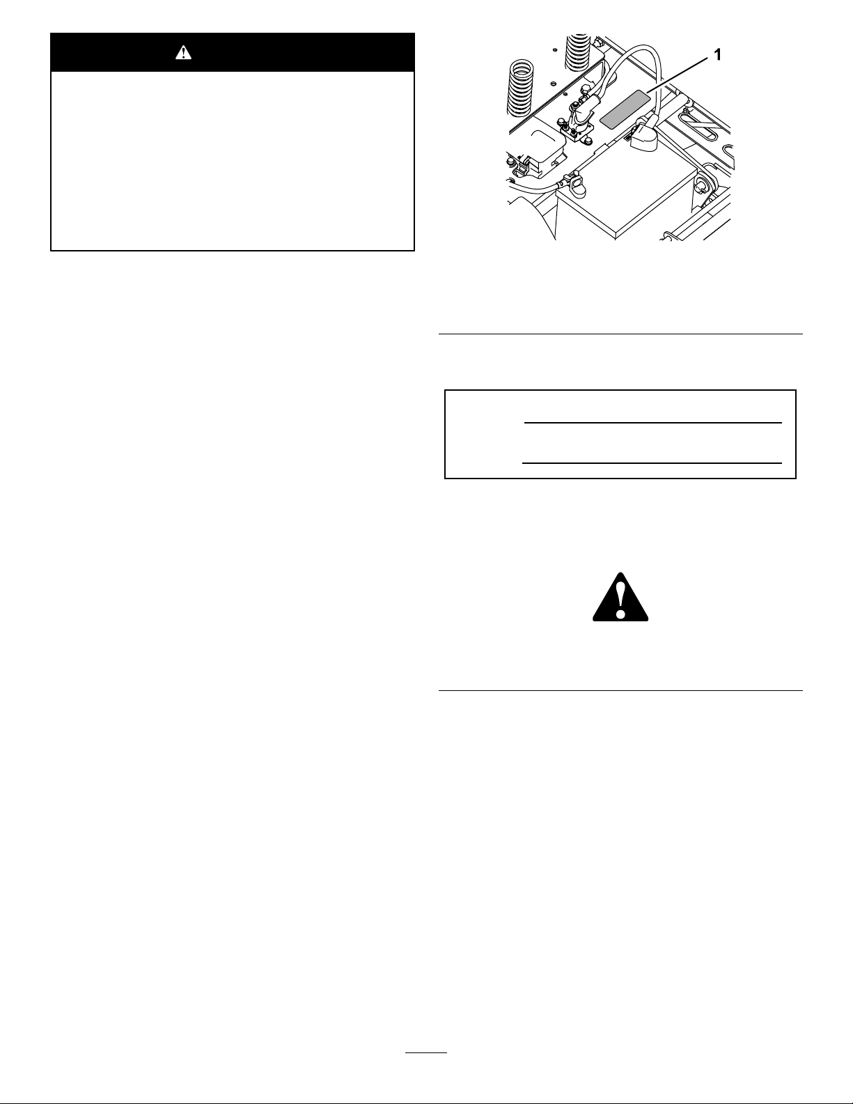
Figure1
Undertheseat
1.Modelandserialnumberplate
Writetheproductmodelandserialnumbersinthespace
below:
ModelNo.
Thegrossornethorsepowerofthisenginewaslaboratory
ratedbytheenginemanufacturerinaccordancewiththe
SocietyofAutomotiveEngineers(SAE)J1940.Ascongured
tomeetsafety,emission,andoperatingrequirements,
theactualenginetorqueonthisclassofmowerwillbe
signicantlylower.
Gotowww .Toro.comtoviewspecicationsonyourmower
model.
Introduction
Thismachineisaride-on,rotary-bladelawnmowerintended
tobeusedbyhomeownersinresidentialapplications.Itis
primarilydesignedforcuttinggrassonwell-maintainedlawns.
Itisnotdesignedforcuttingbrush,mowinggrassandother
growthalongsidehighways,orforagriculturaluses.
Readthisinformationcarefullytolearnhowtooperateand
maintainyourproductproperlyandtoavoidinjuryand
productdamage.Youareresponsibleforoperatingthe
productproperlyandsafely.
SerialNo.
Thismanualidentiespotentialhazardsandhassafety
messagesidentiedbythesafety-alertsymbol(Figure2),
whichsignalsahazardthatmaycauseseriousinjuryordeath
ifyoudonotfollowtherecommendedprecautions.
g000502
Figure2
1.Safety-alertsymbol.
Thismanualuses2wordstohighlightinformation.
Importantcallsattentiontospecialmechanicalinformation
andNoteemphasizesgeneralinformationworthyofspecial
attention.
YoumaycontactTorodirectlyatwww .Toro.comforproduct
safetyandoperationtrainingmaterials,accessoryinformation,
helpndingadealer,ortoregisteryourproduct.
Wheneveryouneedservice,genuineT oroparts,oradditional
information,contactanAuthorizedServiceDealerorToro
CustomerServiceandhavethemodelandserialnumbersof
yourproductready.Figure1identiesthelocationofthe
modelandserialnumbersontheproduct.Writethenumbers
inthespaceprovided.
©2016—TheToro®Company
8111LyndaleAvenueSouth
Bloomington,MN55420
Contactusatwww.Toro.com.
2
PrintedintheUSA
AllRightsReserved
Page 3

Contents
Safety...........................................................................4
GeneralSafety.........................................................4
SlopeIndicator.......................................................5
SafetyandInstructionalDecals.................................6
ProductOverview.........................................................10
Controls...............................................................10
BeforeOperation......................................................12
BeforeOperationSafety..........................................12
RecommendedFuel................................................12
UsingStabilizer/Conditioner...................................12
FillingtheFuelTank...............................................13
CheckingtheEngine-OilLevel.................................13
BreakinginaNewMachine......................................13
ThinkSafetyFirst...................................................13
UsingtheSafety-InterlockSystem.............................15
PositioningtheSeat................................................16
PositioningtheSteeringWheel.................................16
DuringOperation.....................................................16
DuringOperationSafety.........................................16
OperatingtheSmartPark
OperatingtheMowerBlade-ControlSwitch
(PTO)...............................................................17
OperatingtheThrottle............................................18
OperatingtheIgnitionSwitch..................................18
StartingandShuttingOfftheEngine.........................19
DrivingtheMachine...............................................19
StoppingtheMachine.............................................20
MowinginReverse.................................................20
AdjustingtheHeightofCut.....................................20
UsingtheGrassDeector.......................................21
OperatingTips......................................................21
AfterOperation........................................................22
AfterOperationSafety............................................22
PushingtheMachinebyHand..................................22
TransportingtheMachine........................................23
LoadingtheMachine..............................................23
Maintenance.................................................................25
RecommendedMaintenanceSchedule(s)......................25
Pre-MaintenanceProcedures......................................25
MaintenanceandStorage.........................................25
RaisingtheSeat......................................................26
RaisingtheFrontoftheMachine..............................26
Lubrication...............................................................27
GreasingtheBearings.............................................27
EngineMaintenance..................................................27
EngineSafety.........................................................27
ServicingtheAirCleaner.........................................27
ServicingtheEngineOil..........................................28
ServicingtheSparkPlug..........................................31
CleaningtheBlowerHousing...................................31
FuelSystemMaintenance...........................................32
ReplacingtheIn-LineFuelFilter...............................32
ElectricalSystemMaintenance....................................33
ElectricalSystemSafety...........................................33
ChargingtheBattery...............................................33
ServicingtheFuses.................................................34
™
ParkingBrake..................17
DriveSystemMaintenance.........................................35
CheckingtheTirePressure......................................35
ReleasingtheElectricBrake.....................................35
MowerMaintenance...................................................36
ServicingtheCuttingBlades.....................................36
LevelingtheMowerDeck........................................38
RemovingtheMowerDeck.....................................39
InstallingtheMowerDeck.......................................40
ReplacingtheGrassDeector..................................40
MowerBeltMaintenance............................................41
InspectingtheBelts................................................41
ReplacingtheMowerBelt........................................41
Cleaning...................................................................42
CleaningundertheFrontoftheMachine...................42
WashingtheUndersideoftheMower........................42
Storage........................................................................43
CleaningandStorage..............................................43
Troubleshooting...........................................................45
Schematics...................................................................47
3
Page 4

Safety
ThismachinehasbeendesignedinaccordancewithANSI
B71.1-2012.
GeneralSafety
Thisproductiscapableofamputatinghandsandfeetand
ofthrowingobjects.Alwaysfollowallsafetyinstructionsto
avoidseriouspersonalinjury.
Usingthisproductforpurposesotherthanitsintendeduse
couldprovedangeroustoyouandbystanders.
•ReadandunderstandthecontentsofthisOperator’ sManual
beforeyoustarttheengine.Ensurethateveryoneusing
thisproductknowshowtouseitandunderstandsthe
warnings.
•Donotputyourhandsorfeetnearmovingcomponents
ofthemachine.
•Donotoperatethemachinewithoutallguardsandother
safetyprotectivedevicesinplaceandworkingonthe
machine.
•Keepclearofanydischargeopening.Keepbystandersa
safedistanceawayfromthemachine.
•Keepchildrenoutoftheoperatingarea.Neverallow
childrentooperatethemachine.
•Stopthemachineandshutofftheenginebeforeservicing,
fueling,oruncloggingthemachine.
Improperlyusingormaintainingthismachinecanresult
ininjury.Toreducethepotentialforinjury,complywith
thesesafetyinstructionsandalwayspayattentiontothe
safety-alertsymbol,whichmeansCaution,Warning,or
Danger—personalsafetyinstruction.Failuretocomplywith
theseinstructionsmayresultinpersonalinjuryordeath.
Youcanndadditionalitemsofsafetyinformationintheir
respectivesectionsthroughoutthismanual.
4
Page 5
SlopeIndicator
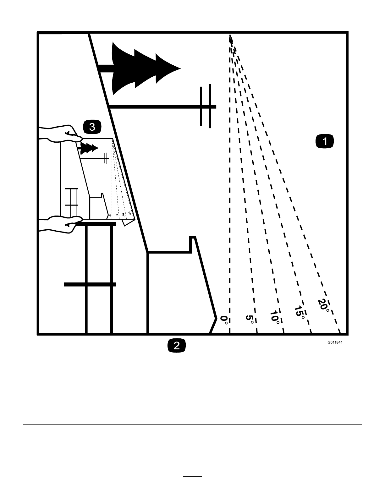
G011841
Figure3
Thispagemaybecopiedforpersonaluse.
1.Themaximumslopeyoucansafelyoperatethemachineonis15degrees.Usetheslopecharttodeterminethedegreeofslope
ofhillsbeforeoperating.Donotoperatethismachineonaslopegreaterthan15degrees.Foldalongtheappropriateline
tomatchtherecommendedslope.
2.Alignthisedgewithaverticalsurface,atree,building,fencepole,etc.
3.Exampleofhowtocompareslopewithfoldededge
5
g011841
Page 6
SafetyandInstructionalDecals
Safetydecalsandinstructionsareeasilyvisibletotheoperatorandarelocatednearanyareaofpotential
danger.Replaceanydecalthatisdamagedormissing.
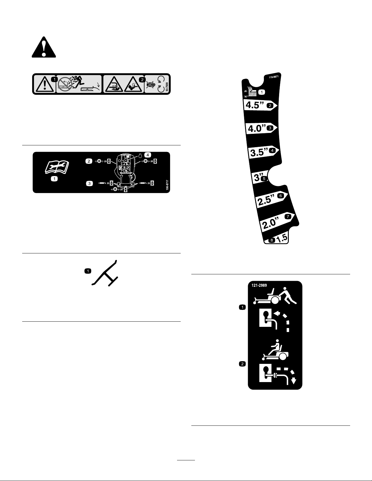
93-7009
1.Warning—don'toperatethemowerwiththedeectorupor
removed;keepthedeectorinplace.
2.Cutting/dismembermenthazardofhandorfoot,mower
blade—stayawayfrommovingparts.
106-8717
decal93-7009
decal106-8717
1.Readtheinstructionsbeforeservicingorperforming
maintenance.
2.Checktirepressureevery25operatinghours.
3.Greaseevery25operatinghours.
4.Engine
Manufacturer'sMark
1.Indicatesthebladeisidentiedasapartfromtheoriginal
machinemanufacturer.
decal119-8871
119-8871
1.Height-of-cut
decaloemmarkt
1.Bypassleverpositionfor
pushingthemachine
6
decal121-2989b
121-2989
2.Bypassleverpositionfor
operatingthemachine
Page 7
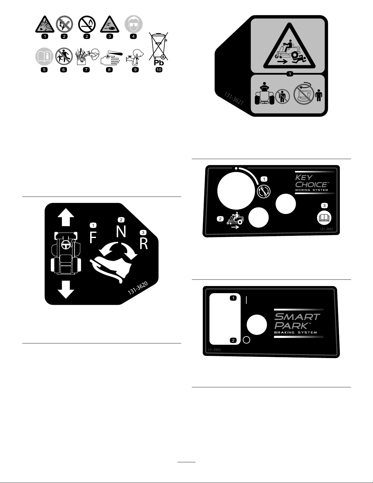
decalbatterysymbols
BatterySymbols
Someorallofthesesymbolsareonyourbattery .
1.Explosionhazard
2.Nore,opename,or
6.Keepbystandersasafe
7.Weareyeprotection;
smoking
3.Causticliquid/chemical
8.Batteryacidcancause
burnhazard
4.Weareyeprotection.9.Flusheyesimmediately
5.ReadtheOperator's
10.Containslead;donot
Manual.
distanceawayfromthe
battery.
explosivegasescan
causeblindnessandother
injuries.
blindnessorsevereburns.
withwaterandgetmedical
helpfast.
discard.
131-3621
1.Crushing/dismembermenthazardofbystanders—keep
bystandersawayfromthemachine;donotstartthe
machinewithbystandersnearby.
131-3665
1.Bladespinning
2.Reverse
3.ReadtheOperator's
Manual.
decal131-3621b
decal131-3665
decal131-3620
131-3620
1.Pedalposition—forward
2.Pedalposition—neutral
3.Pedalposition—reverse
decal131-3955
131-3955
1.On2.Off
7
Page 8

decal132-0872
132-0872
1.Thrownobject
hazard—keepbystanders
awayfromthemachine.
2.Thrownobjecthazard,
raisedbafe—donot
operatethemachinewith
anopendeck;usea
baggerorabafe.
3.Severinghazardofhand
orfoot—keepawayfrom
movingparts.
4.Entanglement
hazard—keepaway
frommovingparts;keep
allguardsandshieldsin
place.
decal132-6863
132-6863
decal121-0771
121-0771
1.Choke4.Slow
2.Fast
3.Continuousvariablesetting
5.Powertake-off(PTO),Bladecontrolswitch
8
Page 9
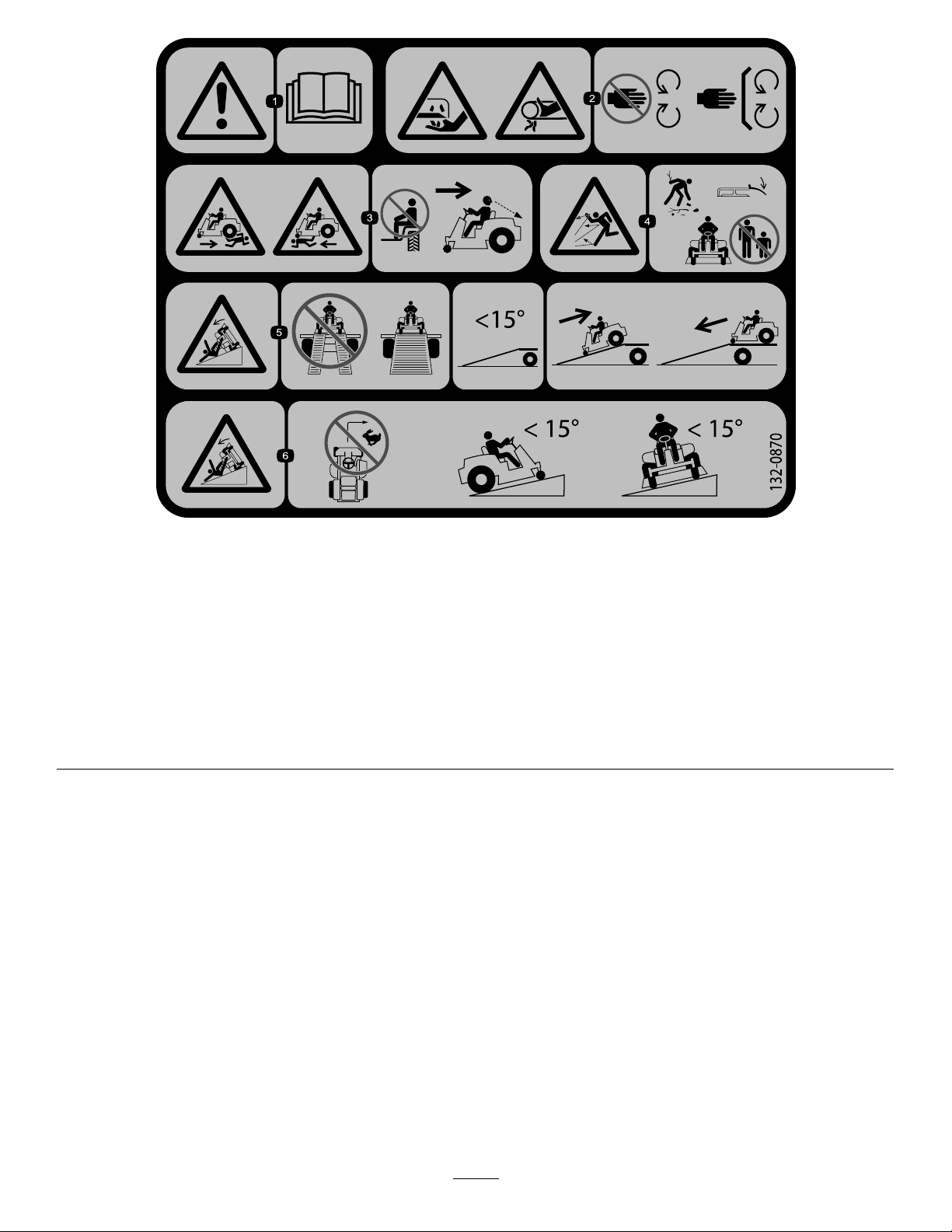
decal132-0870
132-0870
1.Warning—readtheOperator'sManual.
2.Cuttinghazardofhand,mowerblade;
pinchinghazardofhand,belt—keep
handsandfeetawayfrommoving
parts;keepallguardsandshieldsin
place.
3.Bodilyharmhazard—noriders;look
behindyouwhenmowinginreverse.
4.Thrownobjecthazard—keep
bystandersawayfromthemachine;
removedebrisfromtheareabefore
mowing;keepthedeectorshield
down.
5.Ramptippinghazard—whenloading
ontoatrailer,donotusedualramps;
onlyuseasinglerampwideenough
forthemachineandthathasanincline
lessthan15degrees;backupthe
ramp(inreverse)anddriveforwardoff
theramp.
6.Tippinghazardonslopes—donot
makesharp,quickturns;donotuse
slopesgreaterthan15degrees.
9
Page 10
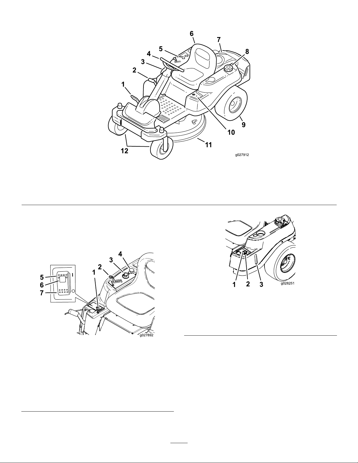
ProductOverview
g027912
1
2
4
5
6
7
8
9
11
12
10
3
5
6
7
g027892
1.Traction-controlpedal
2.Height-of-cutlever5.Controlpanel
3.SmartPark
™
switch6.Operatorseat
4.Steeringwheel
Figure4
7.Engine
8.Fuel-tankcap11.Mowerdeck
9.Reardrivewheel12.Frontcasterwheels
10.KeyChoice
g027912
®
control
Controls
BecomefamiliarwithallcontrolsinFigure4,Figure5,and
Figure6beforeyoustarttheengineandoperatethemachine.
g028251
Figure6
1.Operating–in–Reverse
warninglight
2.KeyChoicekey(bluein
color)
Figure5
1.SmartPark™switch5.Parkingbrake—On
2.Throttle/Chokecontrol
3.Ignitionswitch
4.Blade-controlswitch
(powertake-off)
ControlPanel
6.Parkingbrakeindicator
light
7.Parkingbrake—Off
g027892
IgnitionSwitch
Usethisswitchtostartthemowerengine.Ithas3positions:
START,RUN,andOFF.
3.Fuel-presencewindow
10
Page 11

Throttle/ChokeControl
Attachments/Accessories
Thethrottleandchokecontrolsarecombinedinto1control
lever.Thethrottlecontrolstheenginespeedandhasa
continuous-variablesettingfromSLOWtoFAST.Engagethe
chokebymovingtheleverpasttheFASTsettinguntilitstops
(Figure5).
Blade-ControlSwitch(PowerTakeoff)
Theblade-controlswitch(PTO)engagesanddisengages
powertothemowerblades(Figure5).
Fuel-PresenceWindow
Thefuelwindow ,locatedontheleftsideofthemachine,can
beusedtoverifythepresenceoffuelinthetank(Figure6).
Height-of-CutLever
Usetheheight-of-cutlevertolowerandraisethedeckfrom
theseatedposition.Movingtheleverup(towardyou)raises
thedeckfromthegroundandmovingtheleverdown(away
fromyou)lowersthedecktowardtheground.Adjustthe
height-of-cutonlywhilethemachineisnotmoving(Figure
19).
AselectionofToroapprovedattachmentsandaccessoriesis
availableforusewiththemachinetoenhanceandexpand
itscapabilities.ContactyourAuthorizedServiceDealeror
Distributororgotowww .Toro.comforalistofallapproved
attachmentsandaccessories.
KeyChoice
Thisswitchallowsyoutomowinreversewhenitisactivated.
Toactivateit,turntheswitchtotheONpositionandrelease
itafterthePTOisengaged.Todeactivateit,disengagethe
powertakeoff(PTO)(Figure6).
®
Switch
Operating-in-ReverseWarningLight
TheOperating-in-Reversewarninglightilluminates
wheneveryouusetheKeyChoicekeytodeactivatethe
operating-in-reverseinterlock.Itisareminderthatthe
interlocksystemisdeactivated.Thelightgoesoutwhenever
youdisengagethePTOorshutofftheengine.Whenthelight
ison,lookbehindyouanduseextracautionwhenbackingup.
SmartPark
Theparkingbrakeisactivatedelectronically.
Engagetheparkingbrakeby1ofthefollowingactions:
•PressingtheSmartPark
(Figure5).
•Theparkingbrakeengagesautomaticallywhenyouleave
theseatandthetractioncontrolpedalisintheNEUTRAL
position.
•Theparkingbrakeautomaticallyengages5to6seconds
aftertheignitionswitchisturnedtotheOFFposition(if
itisnotalreadyengaged).
™
Switch
™
switchtotheONposition
Todisengagetheparkingbrake,presstheSmartParkswitch
totheOFFpositionwiththekeyintheRUNposition.
11
Page 12

Operation
Note:Determinetheleftandrightsidesofthemachine
fromthenormaloperatingposition.
BeforeOperation
BeforeOperationSafety
GeneralSafety
•Neverallowchildrenoruntrainedpeopletooperateor
servicethemachine.Localregulationsmayrestrictthe
ageoftheoperator.Theownerisresponsiblefortraining
alloperatorsandmechanics.
•Becomefamiliarwiththesafeoperationoftheequipment,
operatorcontrols,andsafetysigns.
•Knowhowtostopthemachineandshutofftheengine
quickly.
•Checkthatoperator-presencecontrols,safetyswitches,
andshieldsareattachedandfunctioningproperly.Donot
operatethemachineunlesstheyarefunctioningproperly.
•Beforemowing,alwaysinspectthemachinetoensurethat
theblades,bladebolts,andcuttingassembliesareingood
workingcondition.Replacewornordamagedbladesand
boltsinsetstopreservebalance.
•Inspecttheareawhereyouwillusethemachineand
removeallobjectsthatthemachinecouldthrow.
•Evaluatetheterraintodeterminetheappropriate
equipmentandanyattachmentsoraccessoriesrequiredto
operatethemachineproperlyandsafely.
FuelSafety
•Toavoidpersonalinjuryorpropertydamage,useextreme
careinhandlingfuel.Fuelvaporsareammableand
explosive.
•Extinguishallcigarettes,cigars,pipes,andothersources
ofignition.
•Useonlyanapprovedfuelcontainer.
•Donotremovethefuelcaporaddfueltothefueltank
whiletheengineisrunningorwhilehot.
•Donotrefuelthemachineindoors.
•Donotstorethemachineorfuelcontainerwherethere
isanopename,spark,orpilotlight,suchasonawater
heateroronotherappliances.
•Donotllcontainersinsideavehicleoronatruckor
trailerbedwithaplasticliner.Alwaysplacecontainerson
theground,awayfromyourvehiclebeforelling.
•Removetheequipmentfromthetruckortrailerand
refuelitwhileitisontheground.Ifthisisnotpossible,
thenrefuelfromaportablecontainerratherthana
fuel-dispensernozzle.
•Donotoperatethemachinewithouttheentireexhaust
systeminplaceandinproperworkingcondition.
•Keepthefuel-dispensernozzleincontactwiththerimof
thefueltankorcontaineropeningatalltimesuntilfueling
iscomplete.Donotuseanozzlelock-opendevice.
•Ifyouspillfuelonyourclothing,changeyourclothing
immediately.Wipeupanyfuelthatspills.
•Neveroverllthefueltank.Replacethefuelcapand
tightenitsecurely.
•Storefuelinanapprovedcontainerandkeepitoutofthe
reachofchildren.Neverbuymorethana30-daysupply
offuel.
•Donotllthefueltankcompletelyfull.Addfueltothe
fueltankuntilthelevelis6to13mm(1/4to1/2inch)
belowthebottomofthellerneck.Thisemptyspacein
thetankallowsfueltoexpand.
–Avoidprolongedbreathingofvapors.
–Keepyourfaceawayfromthenozzleandfueltank
opening.
–Avoidcontactwithskin;washoffspillswithsoapand
water.
RecommendedFuel
•Forbestresults,useonlyclean,fresh(lessthan30days
old),unleadedgasolinewithanoctaneratingof87or
higher((R+M)/2ratingmethod).
•Ethanol:Gasolinewithupto10%ethanol(gasohol)
or15%MTBE(methyltertiarybutylether)byvolume
isacceptable.EthanolandMTBEarenotthesame.
Gasolinewith15%ethanol(E15)byvolumeisnot
approvedforuse.Neverusegasolinethatcontains
morethan10%ethanolbyvolume,suchasE15
(contains15%ethanol),E20(contains20%ethanol),or
E85(containsupto85%ethanol).Usingunapproved
gasolinemaycauseperformanceproblemsand/orengine
damagewhichmaynotbecoveredunderwarranty.
•Donotusegasolinecontainingmethanol.
•Donotstorefueleitherinthefueltankorfuelcontainers
overthewinterunlessyouuseafuelstabilizer.
•Donotaddoiltogasoline.
UsingStabilizer/Conditioner
Useafuelstabilizer/conditionerinthemachinetoprovide
thefollowingbenets:
•Keepsfuelfreshduringstorageof90daysorless(drain
thefueltankwhenstoringthemachineformorethan
90days)
•Cleanstheenginewhileitruns
•Eliminatesgum-likevarnishbuildupinthefuelsystem,
whichcauseshardstarting
12
Page 13
Important:Donotusefueladditivescontaining
g027243
A
B
E
D
C
methanolorethanol.
Addthecorrectamountoffuelstabilizer/conditioner
tothefuel.
Note:Afuelstabilizer/conditionerismosteffective
whenmixedwithfreshfuel.T ominimizethechanceof
varnishdepositsinthefuelsystem,usefuelstabilizerat
alltimes.
BreakinginaNewMachine
Newenginestaketimetodevelopfullpower.Mowerdecks
anddrivesystemshavehigherfrictionwhennew,placing
additionalloadontheengine.Allow40to50hoursof
break-intimefornewmachinestodevelopfullpowerand
bestperformance.
ThinkSafetyFirst
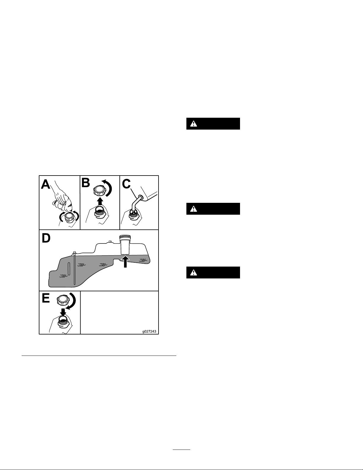
FillingtheFuelTank
1.Parkthemachineonlevelground.
2.Shutofftheengineandengagetheparkingbrake.
3.Cleanaroundthefuel-tankcap.
4.Fillthefueltanktothebottomofthellerneck(Figure
7).
Note:Donotllthefueltankcompletelyfull.The
emptyspaceinthetankallowsthefueltoexpand.
Pleasereadallsafetyinstructionsandsymbolsinthesafety
section.Knowingthisinformationcouldhelpyouor
bystandersavoidinjury.
DANGER
Operatingthemachineonwetgrassorsteepslopes
cancauseslidingandlossofcontrol.
•Donotoperateonslopesgreaterthan15degrees.
•Reducespeedanduseextremecautionon
slopes.
•Donotoperatethemachinenearwater.
DANGER
Wheelsdroppingoveredgescancauserollovers,
whichmayresultinseriousinjury,death,or
drowning.
Donotoperatethemachineneardrop-offs.
Figure7
CheckingtheEngine-OilLevel
Beforeyoustarttheengineandusethemachine,check
theoillevelintheenginecrankcase;refertoCheckingthe
Engine-OilLevel(page28).
DANGER
Operatingthemachinewhiletherollbarisdown
mayleadtoseriousinjuryordeathintheeventofa
rollover.
Alwayskeeptherollbarinthefullyraisedand
lockedpositionandusetheseatbelt.
g027243
13
Page 14
g027830
Figure8
G009027
1
2
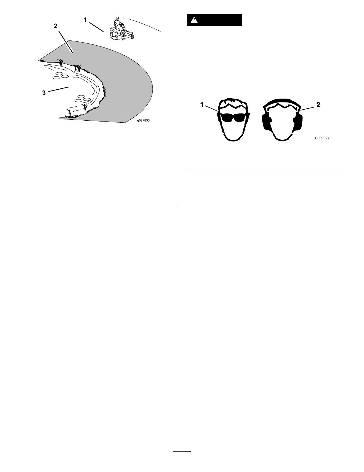
CAUTION
Thismachineproducessoundlevelsinexcessof
85dBAattheoperator’searandcancausehearing
lossthroughextendedperiodsofexposure.
Wearhearingprotectionwhenoperatingthis
machine.
Useprotectiveequipmentforyoureyes,ears,hands,feet,
andhead.
g027830
1.SafeZone—usethe
machinehereonslopes
lessthan15degreesor
atareas.
2.DangerZone—usea
walk-behindmowerand/or
ahandtrimmeronslopes
greaterthan15degrees
andneardrop-offsor
water.
3.Water
g009027
Figure9
1.Weareyeprotection.2.Wearhearingprotection.
14
Page 15

UsingtheSafety-Interlock System
TestingtheSafety-InterlockSystem
1.Sitintheseatwiththeengineoffandensurethatthe
PTOswitchisintheOFFposition.
WARNING
Ifsafety-interlockswitchesaredisconnectedor
damaged,themachinecouldoperateunexpectedly
causingpersonalinjury.
•Donottamperwiththeinterlockswitches.
•Checktheoperationoftheinterlockswitches
daily,andreplaceanydamagedswitchesbefore
operatingthemachine.
UnderstandingtheSafety-Interlock
System
Thesafety-interlocksystemisdesignedforthefollowing:
•Topreventtheenginefromstartingunlessthetraction
pedalisintheNEUTRALposition.
•Toautomaticallyensurethattheparkingbrakeisengaged
andthePTOisoffwhenstartingthemachine.
•Toshutofftheenginewheneverthetractionpedalisnot
intheNEUTRALpositionandyourisefromtheseat.
•Toautomaticallyengagetheparkingbrakeanddisengage
thePTO ,whenyouriseoutoftheseatwiththetraction
pedalintheNEUTRALposition.
•Toshutofftheenginewhenevertheparkingbrakeisnot
engagedandyourisefromtheseat.
2.TurntheignitionkeytotheSTARTposition;thestarter
shouldcrank.Donotstartorshutofftheengineprior
tostep3.
3.TurnthekeytotheONpositionandpushtheSmart
ParkswitchtotheOFFposition.Thebrakeshould
disengageandthebrakelightshouldturnoff.
4.Withthebrakedisengagedandtractionpedalinthe
NEUTRALposition,turntheignitionswitchtothe
STARTposition.Thebrakeshouldautomatically
engage,theengineshouldcrank,andthebrakelight
shouldturnon.
5.WiththeengineoffandthekeyintheONposition,
engagethePTObypullinguptheblade-controlswitch;
youshouldheartheclutchengage.
6.Ensurethatthetractionpedalisinneutralandturn
theignitionswitchtotheSTARTposition.ThePTO
shoulddisengageandtheengineshouldcrankandstart
withoutthebladesmoving.
7.Withtheenginerunning,risefromtheseat.Theengine
shouldremainrunningandthebrakelightshouldbe
on.
8.Returntotheseatanddisengagetheparkingbrakeby
pushingtheSmartParkswitchtotheOFFposition.
Theengineshouldcontinuetorun.
9.Risefromtheseatagain.Thebrakeshould
automaticallyengageandtheengineshouldcontinue
torun.
10.Returntotheseatandengagethebladesbypullingup
theblade-controlswitch.
11.Risefromtheseat.Thebladesshoulddisengageand
theengineshouldcontinuetorun.
12.Returntotheseatandpulluptheblade-controlswitch.
Thebladesshouldengage.Disengagethebladesby
pushingdowntheblade-controlswitch.
13.Pulluptheblade-controlswitchtoengagetheblades.
MovethetractionpedaltotheREVERSEposition.The
bladesshoulddisengage.Movethetractionpedalto
theNEUTRALposition.
14.Pulluptheblade-controlswitchtoengagetheblades.
TurntheKeyChoiceswitchtotheONposition
andreleaseit.Theoperating-in-reverselightshould
illuminate.
15.MovethetractionpedaltotheREVERSEposition.
Thebladesshouldremainengaged.Pushthe
blade-controlswitchintodisengagetheblades.The
operating-in-reverselightshouldturnoff.Movethe
tractionpedaltotheNEUTRALposition.
16.Ifnotengaged,pushtheSmarkParkswitchtotheON
positionandlightlytapthetractionpedalintheeither
15
Page 16

theFORWARDorREVERSEposition.Thebrakeshould
g027249
B
C
A
g027751
B
A
disengageandthebrakelightshouldturnoff.
Note:Tapthepedal,donotfullyengagethepedalas
thatcausesthebrakesystemtobindandnotrelease.
17.Withthebrakereleased,engagethetractionpedal
slightlyandrisefromtheseat.Theengineshouldshut
off.
18.Returntotheseatandturntheignitionkeytothe
OFFposition.Afterseveralseconds,thebrakesystem
shouldengage.
Note:WiththekeyintheOFFposition,thebrakelight
doesnotilluminate.
PositioningtheSeat
PositioningtheSteeringWheel
Thesteeringwheelhas3positionsforoperationand1full-up
position.Usethefull-uppositionforsteppingonandoff
themachineandgettingoutoftheseat.Whenoperatingthe
machine,positionthesteeringwheelwhereyouhavethebest
controlofthemachineandaremostcomfortable.
1.Pressyourfootontothesteering-columnreleaselever.
2.Positionthesteeringwheeltothedesiredposition
(Figure11).
Figure10
g027751
Figure11
DuringOperation
DuringOperationSafety
GeneralSafety
g027249
•Theowner/operatorcanpreventandisresponsiblefor
accidentsthatmaycausepersonalinjuryorproperty
damage.
•Wearappropriateclothing,includingeyeprotection;
slip-resistant,substantialfootwear;andhearing
protection.Tiebacklonghairanddonotwearjewelry.
•Donotoperatethemachinewhileill,tired,orunderthe
inuenceofalcoholordrugs.
•Nevercarrypassengersonthemachineandkeep
bystandersandpetsawayfromthemachineduring
operation.
•Operatethemachineonlyingoodvisibilitytoavoidholes
orhiddenhazards.
•Avoidmowingonwetgrass.Reducedtractioncould
causethemachinetoslide.
•Ensurethatalldrivesareinneutral,theparkingbrake
isengaged,andyouareintheoperatingpositionbefore
youstarttheengine.
16
Page 17

•Keepyourhandsandfeetawayfromthecuttingunits.
G008945
Keepclearofthedischargeopeningatalltimes.
•Lookbehindanddownbeforebackinguptobesureof
aclearpath.
OperatingtheSmartPark
ParkingBrake
Theparkingbrakeisactivatedelectronically.
™
•Usecarewhenapproachingblindcorners,shrubs,trees,
orotherobjectsthatmayobscureyourvision.
•Donotmowneardrop-offs,ditches,orembankments.
Themachinecouldsuddenlyrolloverifawheelgoes
overtheedgeoriftheedgegivesway.
•Stopthebladeswheneveryouarenotmowing.
•Stopthemachineandinspectthebladesafterstrikingan
objectorifthereisanabnormalvibrationinthemachine.
Makeallnecessaryrepairsbeforeresumingoperation.
•Slowdownandusecautionwhenmakingturnsand
crossingroadsandsidewalkswiththemachine.Always
yieldtheright-of-way.
•Disengagethedrivetothecuttingunitandshutoffthe
enginebeforeadjustingtheheightofcut(unlessyoucan
adjustitfromtheoperatingposition).
•Neverrunanengineinanareawhereexhaustgasesare
enclosed.
•Neverleavearunningmachineunattended.
•Beforeleavingtheoperatingposition(includingtoempty
thecatchersortounclogthechute),dothefollowing:
–Stopthemachineonlevelground.
–Disengagethepowertake-offandlowerthe
attachments.
Engagetheparkingbrakeby1ofthefollowingactions:
•PressingtheSmartPark
(Figure5).
™
switchtotheONposition
•Theparkingbrakeengagesautomaticallywhenthe
operatorleavestheseatandthetractioncontrolpedalis
intheNEUTRALposition.
•Theparkingbrakeautomaticallyengages5to6seconds
aftertheignitionswitchisturnedtotheOFFposition(if
itisnotalreadyengaged).
Disengagetheparkingbrakeby1ofthefollowingactions:
•Tapthetraction-controlpedalforwardorreverse.
•PressingthebrakeswitchtotheOFFposition(Figure5).
OperatingtheMower Blade-ControlSwitch(PTO)
Theblade-controlswitch(PTO)startsandstopsthemower
bladesandanypoweredattachments.
EngagingtheBlade-ControlSwitch
(PTO)
–Engagetheparkingbrake.
–Shutofftheengineandremovethekey .
–Waitforallmovingpartstostop.
•Donotoperatethemachinewhenthereistheriskof
lightning.
•Donotusethemachineasatowingvehicle.
•Donotchangethegovernorspeedoroverspeedthe
engine.
•UseaccessoriesandattachmentsapprovedbyToroonly.
SlopeSafety
•Slowdownthemachineanduseextracareonhillsides.
Travelupanddownonhillsides.Turfconditionscan
affectthestabilityofthemachine.
•Avoidturningthemachineonslopes.Ifyoumustturnthe
machine,turnitslowlyandgraduallydownhill,ifpossible.
•Donotturnthemachinesharply .Usecarewhenreversing
themachine.
•Useextracarewhileoperatingthemachinewith
attachments;theycanaffectthestabilityofthemachine.
g008945
Figure12
Note:AlwaysengagethebladeswiththethrottleintheFAST
position(Figure13).
17
Page 18

Figure13
G009174
START
RUN
STOP
G008947
DisengagingtheBlade-ControlSwitch
(PTO)
OperatingtheIgnitionSwitch
1.TurntheignitionkeytotheSTARTposition(Figure16).
Note:Whentheenginestarts,releasethekey.
Important:Donotengagethestarterformore
than5secondsatatime.Iftheenginefailsto
start,wait15secondsbetweenattempts.Failureto
followtheseinstructionscanburnoutthestarter
motor.
Note:Youmayneedmultipleattemptstostartthe
g186693
enginewhenyoustartitthersttimeafterthefuel
systemhasbeenwithoutfuelcompletely.
g008947
Figure16
Figure14
OperatingtheThrottle
YoucanmovethethrottlecontrolbetweentheFASTand
SLOWpositions(Figure15).
AlwaysusetheFASTpositionwhenturningonthemower
deckwiththeblade-controlswitch(PTO).
Figure15
g009174
2.TurntheignitionkeytotheSTOPpositiontoshutoff
theengine.
g187361
18
Page 19

StartingandShuttingOffthe
g027899
B
C
D
E
A
F
DrivingtheMachine
Engine
StartingtheEngine
Note:Awarmorhotenginemaynotrequirechoking.
Important:Donotengagethestarterformorethan
5secondsatatime.Engagingthestartermotorfor
morethan5secondscandamagethestartermotor.If
theenginefailstostart,wait10secondsbeforeoperating
theenginestarteragain.
Thismachinehasthecharacteristicsofbothagardentractor
andazero-turnmachine.Likeagardentractor,themachine
hasafootpedalthatcontrolstheforwardandreversemotion
alongwiththespeed,andithasasteeringwheelthatcontrols
thedirectionandtheturningradius.Likeazero-turnmachine,
thereardrivewheelsoperateindependentlyofeachother,
enablingyoutomakesharpturnsandtoturnindifferent
directionsquickly.Thesecharacteristicsvastlyimprovethe
maneuverabilityofthemachine,buttheymayalsorequire
youtopracticedrivingifyouareunfamiliarwiththistypeof
machine.
WARNING
Themachinecanspinveryrapidly.Y oumaylose
controlofthemachineandcausepersonalinjuryor
damagetothemachine.
•Usecautionwhenmakingturns.
•Slowthemachinedownbeforemakingsharp
turns.
Thethrottlecontrolregulatestheenginespeedasmeasured
inrpm(revolutionsperminute).Placingthethrottlecontrol
intheFASTpositioncanbebestforperformance.Formost
applications,operatingintheFULL-THROTTLEpositionis
desirable.
Figure17
ShuttingOfftheEngine
1.Disengagethebladesbymovingtheblade-control
switchtotheOFFposition(Figure17).
2.MovethethrottlelevertotheFASTposition.
3.TurntheignitionkeytotheOFFpositionandremove
thekey.
DrivingForwardorBackward
1.MovethethrottletotheFASTposition.
2.Releasetheparkingbrake.
3.Placeyourfootontothetraction-controlpedaland
slowlypressthetopofthepedaltogoforward,or
pressonthebottomofthepedaltomovebackward
(Figure18).
Note:Thefartheryoumovethepedalineither
g027899
direction,thefasterthemachinemovesinthat
direction.
g027750
Figure18
1.Forward3.Backward
2.Traction-controlpedal
4.Toslowdown,releasethepressureonthe
traction-controlpedal.
19
Page 20

StoppingtheMachine
Toshutoffthemachine,releasethetraction-controlpedal,
disengagetheblade-controlswitch,ensurethatthethrottle
isintheF ASTposition,engagetheparkingbrake,andturn
theignitionkeytooff.
Note:Remembertoremovethekeyfromtheignitionswitch.
WARNING
Childrenorbystandersmaybeinjuredifthey
moveorattempttooperatethemowerwhileitis
unattended.
AlwaysremoveboththeignitionandKeyChoice
keysandengagetheparkingbrakewhenleavingthe
machineunattended,evenifjustforafewminutes.
MowinginReverse
Themachinehasaninterlockfeaturethatpreventsthemower
deckfrommowingwhilethemachineistravelinginreverse.
IfyoushiftintoreversewiththePTOengaged,thePTO
stops.Ifyouneedtomowwhileinreversegear,youcan
temporarilydeactivatethisinterlock.
4.Performthemowing.
5.Whennishedmowing,removetheKeyChoicekey
(Figure6).
Note:Onceyoudeactivatetheinterlock,itstaysin
thismode—withyourmowerbladeorPTOpowered
attachmentoperatingwheneveryoubackup—andthe
consolelightstaysonuntilyoueitherdisengagethe
PTOorshutofftheengine.
AdjustingtheHeightofCut
Note:Thetransportpositionisthehighestheight-of-cut
positionorcuttingheightat115mm(4-1/2inches)asshown
inFigure19.
Heightofcutiscontrolledbytheleverlocatedtotherightof
theoperatingposition(Figure19).
Note:Donotmowwhilebackingupunlessitisnecessary.
DANGER
Achildorbystandercouldbebackedoverbya
ridingmowerwithbladesengagedandcause
seriouspersonalinjuryordeath.
•Donotmowinreverseunlessabsolutely
necessary.
•Alwayslookbackwardanddownbeforebacking
up.
•UsetheKeyChoiceswitchonlyifyouarecertain
nochildrenorotherbystanderswillappearin
themowingarea.
•AlwaysremoveboththeignitionandKeyChoice
keysandputtheminasafeplaceoutofthe
reachofchildrenorunauthorizeduserswhen
leavingthemachineunattended.
Ifyouarecertainthatyoucansafelymoworoperatean
attachmentinreverse,completethefollowingprocedure:
g028025
Figure19
1.InserttheKeyChoicekeyintotheKeyChoiceswitch
(Figure6).
2.EngagethePTO .
3.TurntheKeyChoicekeyclockwiseuntilitstopsand
releaseit.
Note:Aredlightilluminatingontheconsoleindicates
thattheinterlockhasbeendeactivated.
20
Page 21

UsingtheGrassDeector
OperatingTips
Themowerhasahingedgrassdeectorthatdisperses
clippingstothesideanddowntowardtheturf.
DANGER
Withoutthegrassdeector,dischargecover,or
completegrasscatcherassemblymountedin
place,youandothersareexposedtobladecontact
andthrowndebris.Contactwithrotatingmower
blade(s)andthrowndebriscausesinjuryordeath.
•Neverremovethegrassdeectorfrom
themower,becausethegrassdeector
routesmaterialdowntowardtheturf.Ifthe
grassdeectoriseverdamaged,replaceit
immediately.
•Neverputyourhandsorfeetunderthemower.
•Nevertrytocleardischargeareaormower
bladesunlessyoumovetheblade-controlswitch
totheOFFpositionandrotatetheignitionkey
toOFFposition.Alsoremovethekeyandpull
thewireoffthesparkplug(s).
UsingtheFastThrottleSetting
Forbestmowingandmaximumaircirculation,operatethe
engineattheFASTposition.Airisrequiredtothoroughlycut
grassclippings,sodonotsettheheight-of-cutsolowasto
totallysurroundthemowerinuncutgrass.Alwaystrytohave
1sideofthemowerfreefromuncutgrass,whichallowsair
tobedrawnintothemower.
CuttingaLawnfortheFirstTime
Cutgrassslightlylongerthannormaltoensurethatthe
cuttingheightofthemowerdoesnotscalpanyuneven
ground.However,thecuttingheightusedinthepastis
generallythebestonetouse.Whencuttinggrasslongerthan
15cm(6inches)tall,youmaywanttocutthelawntwiceto
ensureanacceptablequalityofcut.
CuttingaThirdoftheGrassBlade
Itisbesttocutonlyaboutathirdofthegrassblade.Cutting
morethanthatisnotrecommendedunlessgrassissparse,or
itislatefallwhengrassgrowsmoreslowly.
AlternatingtheMowingDirection
Alternatethemowingdirectiontokeepthegrassstanding
straight.Thisalsohelpsdisperseclippingswhichenhances
decompositionandfertilization.
MowingatCorrectIntervals
Grassgrowsatdifferentratesatdifferenttimesoftheyear.
Tomaintainthesamecuttingheight,mowmoreofteninearly
spring.Asthegrassgrowthrateslowsinmidsummer,mow
lessfrequently .Ifyoucannotmowforanextendedperiod,
rstmowatahighcuttingheight,thenmowagain2days
lateratalowerheightsetting.
UsingaSlowerCuttingSpeed
Toimprovecutquality,useaslowergroundspeedincertain
conditions.
AvoidingCuttingTooLow
Whenmowinguneventurf,raisethecuttingheighttoavoid
scalpingtheturf.
StoppingtheMachine
Ifyoumuststoptheforwardmotionofthemachinewhile
mowing,aclumpofgrassclippingsmaydropontoyour
lawn.Toavoidthis,moveontoapreviouslycutareawiththe
bladesengagedoryoucandisengagethemowerdeckwhile
movingforward.
21
Page 22

KeepingtheUndersideoftheMower
g017303
1 2
3
Clean
Cleanclippingsanddirtfromtheundersideofthemower
aftereachuse.Ifgrassanddirtbuildupinsidethemower,
cuttingqualitywilleventuallybecomeunsatisfactory.
MaintainingtheBlade(s)
Maintainasharpbladethroughoutthecuttingseasonbecause
asharpbladecutscleanlywithouttearingorshreddingthe
grassblades.Tearingandshreddingturnsgrassbrownat
theedges,whichslowsgrowthandincreasesthechanceof
disease.Checkthemowerbladesaftereachuseforsharpness,
andforanywearordamage.Filedownanynicksandsharpen
thebladesasnecessary.Ifabladeisdamagedorworn,replace
itimmediatelywithagenuineTororeplacementblade.
AfterOperation
AfterOperationSafety
PushingtheMachinebyHand
Important:Alwayspushthemachinebyhand.Donot
towthemachine,becausedamagemayoccur.
Thismachinehasanelectric-brakemechanism,andtopush
themachine,theignitionkeymustbeintheRUNposition.
Thebatteryneedstobechargedandfunctioningforthe
electricbraketobedisengaged.
PushingtheMachine
1.Parkthemachineonalevelsurface,anddisengagethe
blade-controlswitch.
2.Engagetheparkingbrake,shutofftheengine,and
waitforallmovingpartstostopbeforeleavingthe
operatingposition.
3.Locatethebypassleversontheframeonbothsidesof
theengine.
4.Movethebypassleversforwardthroughthekeyhole
anddowntolocktheminplace(Figure20).
Note:Dothisforeachlever.
GeneralSafety
•Cleangrassanddebrisfromthecuttingunits,mufers,
andenginecompartmenttohelppreventres.Cleanup
oilorfuelspills.
•Shutoffthefuelbeforestoringortransportingthe
machine.
•Disengagethedrivetotheattachmentwheneveryouare
transportingornotusingthemachine.
•Usefull-widthrampsforloadingthemachineintoa
trailerortruck.
•Tiethemachinedownsecurelyusingstraps,chains,cable,
orropes.Bothfrontandrearstrapsshouldbedirected
downandoutwardfromthemachine.
•Allowtheenginetocoolbeforestoringthemachinein
anyenclosure.
•Shutoffthefuelbeforestoringortransportingthe
machine.
•Neverstorethemachineorfuelcontainerwherethereis
anopename,spark,orpilotlight,suchasonawater
heateroronotherappliances.
5.Turntheignitionkeyonanddisengagetheparking
brake.
Note:Donotstartthemachine.
Figure20
1.Bypass-leverlocations
2.Leverpositionfor
operatingthemachine
3.Leverpositionforpushing
themachine
g017303
6.Whennished,ensurethatthekeyhasbeenreturnedto
theSTOPpositiontoavoiddrainingthebatterycharge.
Note:Ifthemachinefailstomove,theelectricbrakemay
stillbeengaged.Youcanreleasetheelectricbrakemanuallyif
necessary;refertoReleasingtheElectricBrake(page35).
22
Page 23

OperatingtheMachine
LoadingtheMachine
Movethebypassleversrearwardthroughthekeyholeand
downtolocktheminplaceasshowninFigure20.
Note:Dothisforeachlever.
TransportingtheMachine
Useaheavy-dutytrailerortrucktotransportthemachine.
Ensurethatthetrailerortruckhasallnecessarybrakes,
lighting,andmarkingasrequiredbylaw .Pleasecarefullyread
allthesafetyinstructions.Knowingthisinformationcould
helpyou,yourfamily,pets,orbystandersavoidinjury.
WARNING
Drivingonthestreetorroadwaywithout
turnsignals,lights,reectivemarkings,ora
slow-moving-vehicleemblemisdangerousandcan
leadtoaccidents,causingpersonalinjury.
Donotdrivethemachineonapublicstreetor
roadway.
1.Ifyouareusingatrailer,connectittothetowing
vehicleandconnectthesafetychains.
2.Ifapplicable,connectthetrailerbrakes.
3.Loadthemachineontothetrailerortruck.
4.Shutofftheengine,removethekey,engagetheparking
brake,andclosethefuelvalve.
5.Tiedownthemachinenearthefrontcasterwheelsand
therearbumper(Figure21).
Useextremecautionwhenloadingorunloadingmachines
ontoatraileroratruck.Useafull-widthrampthatiswider
thanthemachineforthisprocedure.Backuptherampand
driveforwarddowntheramp(Figure22).
Figure22
1.Backthemachineupthe
ramp.
Important:Donotusenarrowindividualrampsfor
eachsideofthemachine.
2.Drivethemachineforward
downtheramp.
WARNING
Loadingamachineontoatrailerortruckincreases
thepossibilityoftip-overandcouldcauseserious
injuryordeath(Figure23).
•Useextremecautionwhenoperatingamachine
onaramp.
•Useonlyafull-widthramp;donotuseindividual
rampsforeachsideofthemachine.
•Donotexceeda15-degreeanglebetweenthe
rampandthegroundorbetweentherampand
thetrailerortruck.
g028294
Figure21
•Ensurethatthelengthoframpisatleast4times
aslongastheheightofthetrailerortruckbed
totheground.Thisensuresthattherampangle
doesnotexceed15degreesonatground.
•Backuprampsanddriveforwarddownramps.
g027708
•Avoidsuddenaccelerationordecelerationwhile
drivingthemachineonarampasthiscould
causealossofcontroloratip-oversituation.
23
Page 24

g027996
5
1
2
6
Figure23
g027996
1.Full-widthrampinstowed
position
2.Sideviewoffull-width
rampinloadingposition
3.Notgreaterthan
15degrees
4.Rampisatleast4times
aslongastheheightof
thetrailerortruckbedto
theground
5.H=heightofthetraileror
truckbedtotheground
6.Trailer
24
Page 25

Maintenance
Note:Determinetheleftandrightsidesofthemachinefromthenormaloperatingposition.
RecommendedMaintenanceSchedule(s)
MaintenanceService
Interval
Aftertherst5hours
Beforeeachuseordaily
Aftereachuse
Every25hours
Every50hours
Every100hours
Beforestorage
MaintenanceProcedure
•Changetheengineoilandlter.
•Cleanandchecktheaircleanerfoamelement.
•Checktheengine-oillevel.
•Inspecttheblades.
•Inspectthegrassdeectorfordamage.
•Checkandcleanthefrontofthemachine.
•Cleanthemower-deckhousing.
•Greaseallthelubricationpoints.
•Checktirepressure.
•Checkthebeltsforwearorcracks.
•Replacetheaircleanerpaperelement.
•Checkthesparkplug.
•Changetheengineoil(changeitmoreoftenunderaheavyloadorinhigh
temperatures).
•Changetheengine-oillter.
•Replacethesparkplug.
•Cleantheblowerhousing(moreoftenunderextremelydusty,dirtyconditions).
•Replacethein-linefuellter.
•Chargethebatteryanddisconnectbatterycables.
•Performallmaintenanceprocedureslistedabovebeforestorage.
•Paintanychippedsurfaces.
CAUTION
Ifyouleavethekeyintheignitionswitch,someonecouldaccidentlystarttheengineandseriouslyinjure
youorotherbystanders.
Removethekeyfromtheignitionanddisconnectthewirefromthesparkplugbeforeyoudoany
maintenance.Setthewireasidesothatitdoesnotaccidentallycontactthesparkplug.
Pre-Maintenance
Procedures
•Lettheenginecoolbeforestoringthemachine.
•Donotstorethemachineorfuelnearamesordrain
thefuelindoors.
•Donotallowuntrainedpersonneltoservicethemachine.
MaintenanceandStorage
•Beforerepairingthemachinedothefollowing:
–Disengagethedrives.
–Engagetheparkingbrake.
–Shutofftheengineandremovethekey .
–Disconnectthespark-plugwire.
•Parkthemachineonalevelsurface.
•Cleangrassanddebrisfromthecuttingunit,drives,
mufers,andenginetohelppreventres.
•Cleanupoilorfuelspills.
•Usejackstandstosupportthemachineand/or
componentswhenrequired.
•Carefullyreleasepressurefromcomponentswithstored
energy.
•Disconnectthebatteryorremovethespark-plugwire
beforemakinganyrepairs.Disconnectthenegative
terminalrstandthepositiveterminallast.Connectthe
positiveterminalrstandnegativelast.
•Usecarewhencheckingtheblades.Wraptheblade(s)
orwearthicklypaddedgloves,andusecautionwhen
25
Page 26

servicingthem.Onlyreplaceblades;donotstraighten
orweldthem.
•Keepyourhandsandfeetawayfrommovingparts.
Ifpossible,donotmakeadjustmentswiththeengine
running.
•Keepallpartsingoodworkingconditionandallhardware
tightened,especiallytheblade-attachmentbolts.Replace
allwornordamageddecals.
•Neverinterferewiththeintendedfunctionofasafety
deviceorreducetheprotectionprovidedbyasafety
device.Checktheirproperoperationregularly.
•Toensureoptimumperformanceandcontinuedsafety
certicationofthemachine,useonlygenuineToro
replacementpartsandaccessories.Replacementparts
andaccessoriesmadebyothermanufacturerscouldbe
dangerous,andsuchusecouldvoidtheproductwarranty.
•Checktheparkingbrakeoperationfrequently.Adjustand
serviceasrequired.
RaisingtheSeat
Ensurethattheparkingbrakeisengagedandlifttheseat
forward.
Youcanaccessfollowingcomponentsbyraisingtheseat:
•Serialplate
•Servicedecal
•Seat-adjustmentbolts
•Fuellter
•Batteryandbatterycables
RaisingtheFrontofthe Machine
Ifyouneedtoraisethefrontofthemachine,usethevery
frontedgeasshowninFigure24.
Important:Topreventdamagetothesteering
mechanism,ensurethattheveryfrontedgeofthe
machineisusedforjackingpoints.
g028320
Figure24
26
Page 27

Lubrication
g020242
EngineMaintenance
GreasingtheBearings
ServiceInterval:Every25hours—Greaseallthelubrication
points.
GreaseType:No.2lithiumgrease
1.Parkthemachineonalevelsurface,anddisengagethe
blade-controlswitch.
2.Ensurethattheparkingbrakeisengaged,shutoffthe
engine,removethekey,andwaitforallmovingpartsto
stopbeforeleavingtheoperatingposition.
3.Cleanthegreasettings(Figure25andFigure26)with
arag.
Note:Makesuretoscrapeanypaintoffthefrontof
thetting(s).
EngineSafety
Shutofftheenginebeforecheckingtheoiloraddingoilto
thecrankcase.
ServicingtheAirCleaner
ServiceInterval:Beforeeachuseordaily—Cleanandcheck
theaircleanerfoamelement.
Every50hours—Replacetheaircleanerpaper
element.
Note:Servicetheaircleanermorefrequently(everyfew
hours)ifoperatingconditionsareextremelydustyorsandy.
RemovingtheFoamandPaper
Elements
1.Parkthemachineonalevelsurface,disengagethe
blade-controlswitch(PTO),engagetheparkingbrake,
shutofftheengine,removethekey,andwaitforall
movingpartstostopbeforeleavingtheoperating
position..
Figure25
1.Frontcastertire
Figure26
Locatedontheseat-panunderside
1.Readtheinstructions
beforeservicingor
performingmaintenance
2.Checkthetirepressure
every25operatinghours
4.Connectagreaseguntoeachtting(Figure25and
Figure26).
5.Pumpgreaseintothettingsuntilgreasebeginsto
oozeoutofthebearings.
3.Greaseevery25operating
hours
4.Engine
2.Cleanaroundtheaircleanertopreventdirtfrom
gettingintotheengineandcausingdamage.
g027752
decal106-8717
3.Removetheair-cleanercoverbyunscrewingthe2
knobs(Figure27).
g020242
Figure27
1.Air-cleanercover2.Knobs
4.Carefullyremovethefoamandpaperlterelements
fromtheair-cleanerhousing(Figure28).
27
Page 28
g020243
3
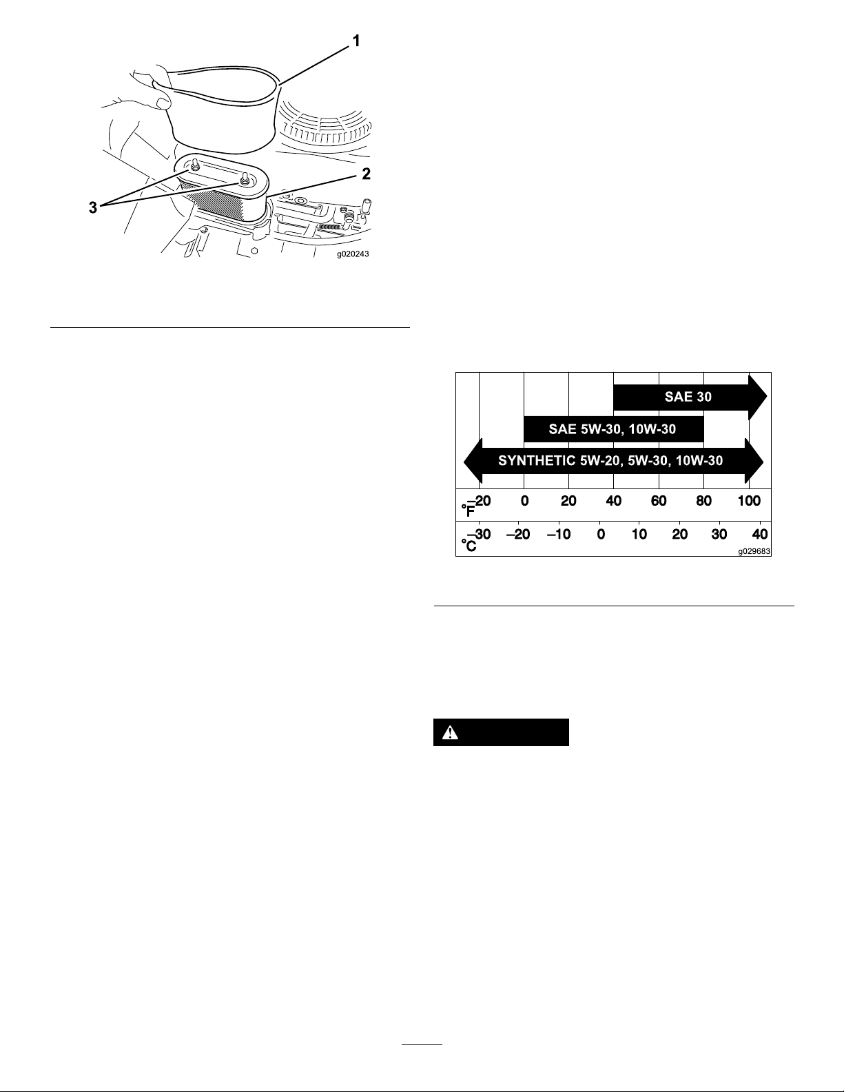
InstallingtheFoamandPaperElements
SAE 5W -30, 10W -30
SAE 30
SYNTHETIC 5W -20, 5W -30, 10W -30
g029683
Important:Topreventenginedamage,alwaysoperate
theenginewiththecompletefoamandpaperaircleaner
assemblyinstalled.
1.Installthefoamlterontothepaperlter(Figure28).
2.Installthefoamandpaperlterontotheair-cleaner
housing.
3.Installtheair-cleanercover,andtightenthe2knobs
(Figure27).
Figure28
1.Foamelement2.Paperelement
5.Separatethefoamandpaperelements.
CleaningtheFoamandPaperElements
FoamElement:
1.Washthefoamelementinliquidsoapandwarmwater.
2.Whentheelementisclean,rinseitthoroughly.
3.Drytheelementbysqueezingitinacleancloth.
Note:Donotoiltheelement.
Important:Replacethefoamelementifitistorn
orworn.
4.Installthefoamelementontoacleanpaperelement.
PaperElement:
1.Tapthepaperelementonasolid,atsurface,andblow
itoutfromtheinsidewithcompressedairtoremove
dustanddirt.
2.Inspecttheelementfortears,anoilylm,anddamage
totherubberseal.
Important:Donotcleanthepaperelementwith
liquids,suchassolvents,gasoline,orkerosene.
Replacethepaperelementifitisdamagedor
cannotbecleanedthoroughly.
3.Cleantheinsideoftheair-cleanercoverofalldirt,dust,
anddebris.
g020243
ServicingtheEngineOil
OilType:Detergentoil(APIserviceSF ,SG,SH,SJ,or
higher)
CrankcaseCapacity:withlter—1.4L(1.5USqt)
Viscosity:Seethetablebelow.
g029683
Figure29
CheckingtheEngine-OilLevel
ServiceInterval:Beforeeachuseordaily
Note:Checktheoilwhentheengineiscold.
WARNING
Contactwithhotsurfacesmaycausepersonal
injury.
Keephands,feet,face,clothing,andotherbody
partsawaythemuferandotherhotsurfaces.
Important:Donotoverllthecrankcasewithoil,
becausedamagetotheenginemayresult.Donotrun
enginewithoilbelowtheLowmark,becausetheengine
maybedamaged.
1.Parkthemachineonalevelsurface,disengagethe
blade-controlswitch,shutofftheengine,engagethe
parkingbrake,andremovethekey.
2.Makesurethattheengineisstopped,level,andiscool,
sotheoilhashadtimetodrainintothesump.
28
Page 29

3.Tokeepdirt,grassclippings,etc.,outoftheengine,
B
A
C
D
E
G029368
F
G H
I J K
B
A
C
E F
D
G
H
g029369
cleantheareaaroundtheoil-llcapanddipstickbefore
removingit(Figure30).
ChangingtheEngineOilandFilter
ServiceInterval:Aftertherst5hours
Every100hours(changeitmoreoftenunderaheavy
loadorinhightemperatures).
Every100hours
g029368
Figure30
g029369
Figure31
5.Changetheengine-oillter.
Note:Changetheengine-oilltermorefrequentlywhenthe
operatingconditionsareextremelydustyorsandy.
1.Parkthemachine,sothattherightsideisslightly
lowerthantheleftside,toensurethattheoildrains
completely.
2.DisengagethePTOandengagetheparkingbrake.
3.Shutofftheengine,waitforallmovingpartstostop,
andremovethekeybeforeleavingtheoperating
position.
4.Draintheoilfromtheengine.
Note:Ensuretheoil-ltergaskettouchestheengine,
andthenturnthelteranextra3/4turn.
29
Page 30

B
A
C D
E
F
3/4
g027477
Figure32
B
A
C
D
E
F
g027484
6.Slowlypourapproximately80%ofthespeciedoil
intothellertubeandslowlyaddtheadditionaloilto
bringittotheFullmark(Figure33).
g027484
Figure33
g027477
30
Page 31

ServicingtheSparkPlug
B
A
g027478
B
A
g027479
InstallingtheSparkPlug
ServiceInterval:Every50hours—Checkthesparkplug.
Every100hours—Replacethesparkplug.
Ensurethattheairgapbetweenthecenterandsideelectrodes
iscorrectbeforeinstallingthesparkplug.Useasparkplug
wrenchforremovingandinstallingthesparkpluganda
gappingtoolorfeelergaugetocheckandadjusttheairgap.
Installanewsparkplugifnecessary.
Type:Champion
BCPR6ES
AirGap:0.76mm(0.03inch)
®
RC12YC,Autolite
®
3924,orNGK
®
RemovingtheSparkPlug
1.Disengagetheblade-controlswitch,engagetheparking
brake,shutofftheengine,andremovethekey.
2.Beforeremovingthesparkplug(s),cleanthearea
aroundthebaseoftheplugtokeepdirtanddebrisout
oftheengine.
3.Removethesparkplug(Figure34).
Tightenthesparkplugto20N∙m(15ft-lb).
g027480
Figure36
Figure34
CheckingtheSparkPlug
Important:Donotcleanthesparkplug(s).Always
replacethesparkplug(s)whenithas:ablackcoating,
wornelectrodes,anoilylm,orcracks.
Note:Ifyouseelightbrownorgrayontheinsulator,the
engineisoperatingproperly.Ablackcoatingontheinsulator
usuallymeanstheaircleanerisdirty.
Setthegapto0.76mm(0.030inch).
CleaningtheBlowerHousing
ServiceInterval:Every100hours/Yearly(whichevercomes
rst)
g027478
Toensurepropercooling,makesurethatthegrassscreen,
coolingns,andotherexternalsurfacesoftheengineare
keptcleanatalltimes.
Cleanthecoolingnsandexternalsurfacesasnecessary.
Makesurethatthecoolingshroudsareinstalled.Torquethe
blowerhousingscrewsto7.5N·m(5.5ft-lb).
Important:Operatingtheenginewithablocked
grassscreen,dirtyorpluggedcoolingns,and/or
coolingshroudsremoved,causesenginedamagedue
tooverheating.
g027479
Figure35
31
Page 32

FuelSystem
g027506
Maintenance
DANGER
Incertainconditions,fuelisextremelyammable
andhighlyexplosive.Areorexplosionfromfuel
canburnyou,others,andcandamageproperty.
•Performanyfuel-relatedmaintenancewhenthe
engineiscold.Dothisoutdoorsinanopenarea.
Wipeupanyfuelthatspills.
•Neversmokewhendrainingfuel,andstayaway
fromanopenameorwhereasparkmayignite
thefuelfumes.
ReplacingtheIn-LineFuel Filter
ServiceInterval:Every100hours—Replacethein-linefuel
lter.
g027506
Neverinstalladirtylterifitisremovedfromthefuelline.
1.Parkthemachineonalevelsurfaceanddisengagethe
blade-controlswitch.
2.Engagetheparkingbrake,shutofftheengine,remove
thekey ,andwaitforallmovingpartstostopbefore
leavingtheoperatingposition.
g033082
Figure37
32
Page 33

ElectricalSystem
G005072
1
2
3
4
5
6
7
Maintenance
ElectricalSystemSafety
•Disconnectthebatterybeforerepairingthemachine.
Disconnectthenegativeterminalrstandthepositive
last.Connectthepositiveterminalrstandthenegative
last.
•Chargethebatteryinanopen,well-ventilatedarea,away
fromsparksandames.Unplugthechargerbefore
connectingordisconnectingthebattery.Wearprotective
clothinganduseinsulatedtools.
WARNING
CALIFORNIA
Proposition65Warning
Batteryposts,terminals,andrelated
accessoriescontainleadandleadcompounds,
chemicalsknowntotheStateofCalifornia
tocausecancerandreproductiveharm.
Washhandsafterhandling.
WARNING
Incorrectbatterycableroutingcoulddamage
themachineandcablescausingsparks.
Sparkscancausethebatterygassesto
explode,resultinginpersonalinjury.
•Alwaysdisconnectthenegative(black)
batterycablebeforedisconnectingthe
positive(red)cable.
•Alwaysconnectthepositive(red)battery
cablebeforeconnectingthenegative
(black)cable.
5.Slidetherubbercoverupthepositive(red)cable.
Disconnectthepositive(red)cablefromthebattery
post(Figure38).Retainallfasteners.
6.Removethebatteryhold-downandliftthebattery
fromthebatterytray(Figure38).
ChargingtheBattery
RemovingtheBattery
WARNING
Batteryterminalsormetaltoolscouldshortagainst
metalmachinecomponents,causingsparks.Sparks
cancausethebatterygassestoexplode,resulting
inpersonalinjury.
•Whenremovingorinstallingthebattery,donot
allowthebatteryterminalstotouchanymetal
partsofthemachine.
•Donotallowmetaltoolstoshortbetween
thebatteryterminalsandmetalpartsofthe
machine.
1.Parkthemachineonalevelsurfaceanddisengagethe
blade-controlswitch.
2.Engagetheparkingbrake,shutofftheengine,remove
thekey ,andwaitforallmovingpartstostopbefore
leavingtheoperatingposition.
3.Raisetheseattoaccessthebattery.
4.Disconnectthenegative(black)groundcablefromthe
batterypost(Figure38).Retainallfasteners.
g005072
Figure38
1.Battery5.Negativebatterypost
2.Positivebatterypost6.Wingnut,washer,andbolt
3.Bolt,washer,andnut7.Batteryhold-down
4.T erminalboot
ChargingtheBattery
ServiceInterval:Beforestorage—Chargethebatteryand
disconnectbatterycables.
1.Removethebatteryfromthechassis;refertoRemoving
theBattery(page33).
2.Chargethebatteryforaminimumof1hourat6to
10A.
Important:Donotoverchargethebattery.
3.Whenthebatteryisfullycharged,unplugthecharger
fromtheelectricaloutlet,thendisconnectthecharger
leadsfromthebatteryposts(Figure39).
33
Page 34

ServicingtheFuses
30
25
30
25
G014540
2
1
Theelectricalsystemisprotectedbyfuses.Itrequires
nomaintenance;however,ifafuseblows,checkthe
component/circuitforamalfunctionorshort.
Fusetype:
•Main—F1(30A,blade-type)
•ChargeCircuit—F2(25A,blade-type)
Figure39
1.Positivebatterypost
2.Negativebatterypost
3.Red(+)chargerlead
4.Black(-)chargerlead
InstallingtheBattery
1.Positionthebatteryinthetray(Figure38).
2.Installthepositive(red)batterycabletothepositive(+)
batteryterminalusingthefastenersremovedpreviously.
3.Installthenegativebatterycabletothenegative(-)
batteryterminalusingthefastenersremovedpreviously.
4.Slidetheredterminalbootontothepositive(red)
batterypost.
5.Securethebatterywiththehold-down(Figure38).
6.Lowertheseat.
g000538
1.Removethescrewssecuringthecontrolpaneltothe
machine.
Note:Retainallfasteners.
2.Liftthecontrolpaneuptoaccessthemainwireharness
andfuseblock(Figure40).
3.Toreplaceafuse,pulloutonthefusetoremoveit
(Figure40).
g014540
Figure40
1.Main(30A)2.Chargecircuit(25A)
4.Returnthecontrolpaneltoitsoriginalposition.
Note:Usethescrewsremovedpreviouslytosecure
thepaneltothemachine.
34
Page 35

DriveSystem
Maintenance
ReleasingtheElectricBrake
Youcanmanuallyreleasetheelectricbrakebyrotatingthe
linkarmsforward.Oncetheelectricbrakeisenergized,the
brakeresets.
CheckingtheTirePressure
ServiceInterval:Every25hours—Checktirepressure.
Maintaintheairpressureinthefrontandreartiresas
specied.Uneventirepressurecancauseunevencut.Check
thepressureatthevalvestem(Figure41).Checkthetires
whentheyarecoldtogetthemostaccuratepressurereading.
Refertothemaximumpressuresuggestedbythetire
manufactureronthesidewallofthecasterwheeltires.
Inatethereardrivewheeltiresto90kPa(13psi).
g000554
Figure41
1.Valvestem
1.TurntheignitionkeytotheOFFpositionordisconnect
thebattery.
2.Locatetheshaftontheelectricbrakewherethebrake
linkarmsareconnected(Figure42).
3.Rotatetheshaftforwardtoreleasethebrake.
g027911
Figure42
1.Brake-linkarmontheelectricbrakecontrolmodule
2.Left,reartire
35
Page 36

MowerMaintenance
G014972
1
2
3
G014973
1
2
3
ServicingtheCuttingBlades
Toensureasuperiorqualityofcut,keepthebladessharp.For
convenientsharpeningandreplacement,keepextrablades
onhand.
BladeSafety
Awornordamagedbladecanbreak,andapieceoftheblade
couldbethrowntowardyouorbystanders,resultinginserious
personalinjuryordeath.Tryingtorepairadamagedblade
mayresultindiscontinuedsafetycerticationoftheproduct.
•Inspectthebladesperiodicallyforwearordamage.
•Usecarewhencheckingtheblades.Wrapthebladesor
weargloves,andusecautionwhenservicingtheblades.
Onlyreplaceorsharpentheblades;neverstraightenor
weldthem.
CheckingforBentBlades
Note:Themachinemustbeonalevelsurfaceforthe
followingprocedure.
1.Raisethemowerdecktothehighestheight-of-cut
position.
2.Whilewearingthicklypaddedgloves,orotheradequate
handprotection,slowlyrotatethebladetobemeasure
intoapositionthatallowseffectivemeasurementofthe
distancebetweenthecuttingedgeandthelevelsurface
themachineison(Figure44).
•Onmulti-bladedmachines,takecareasrotating1blade
cancauseotherbladestorotate.
BeforeInspectingorServicingthe
Blades
Parkthemachineonalevelsurface,disengagethe
blade-controlswitch,engagetheparkingbrake,shutoffthe
engine,andremovethekey.
InspectingtheBlades
ServiceInterval:Beforeeachuseordaily
1.Inspectthecuttingedges(Figure43).
2.Iftheedgesarenotsharporhavenicks,removeand
sharpentheblade;refertoSharpeningtheBlades(page
37).
3.Inspecttheblades,especiallyinthecurvedarea.
4.Ifyounoticeanycracks,wear,oraslotforminginthis
area,immediatelyinstallanewblade(Figure43).
g014972
Figure44
1.Deck3.Blade
2.Spindlehousing
3.Measurefromthetipofthebladetotheatsurface
(Figure45).
g014973
Figure45
1.Blade(inpositionformeasuring)
2.Levelsurface
3.Measureddistancebetweenbladeandthesurface(A)
4.Rotatethesameblade180degreessothattheopposing
cuttingedgeisnowinthesameposition(Figure46).
g006530
Figure43
1.Cuttingedge3.Wear/slotforming
2.Curvedarea4.Crack
36
Page 37

G014974
1
2
3
Figure46
G014973
1
2
3
1.Blade(sidepreviouslymeasured)
2.Measurement(positionusedpreviously)
3.Opposingsideofbladebeingmovedintomeasurement
position
RemovingtheBlades
Replacethebladesiftheyhitasolidobject,orifthebladeis
outofbalanceorbent.
1.Holdthebladeendusingaragorthicklypaddedglove.
2.Removethebladebolt,curvedwasher,andbladefrom
thespindleshaft(Figure48).
g014974
5.Measurefromthetipofthebladetotheatsurface
(Figure47).
Note:Thevarianceshouldbenomorethan3mm
(1/8inch).
Figure47
1.Oppositebladeedge(inpositionformeasuring)
2.Levelsurface
3.Secondmeasureddistancebetweenbladeandsurface(B)
A.IfthedifferencebetweenAandBisgreaterthan
3mm(1/8inch),replacethebladewithanew
blade;refertoRemovingtheBlades(page37)and
InstallingtheBlades(page38).
Note:Ifabentbladeisreplacedwithanew
blade,andthedimensionobtainedcontinuesto
exceed3mm(1/8inch),thebladespindlecould
bebent.ContactanAuthorizedToroDealerfor
service.
g000551
Figure48
1.Sailareaoftheblade
2.Blade
3.Curvedwasher
4.Bladebolt
5.Bladestiffener
SharpeningtheBlades
1.Usealetosharpenthecuttingedgeatbothendsof
theblade(Figure49).
Note:Maintaintheoriginalangle.
Note:Thebladeretainsitsbalanceifthesameamount
ofmaterialisremovedfrombothcuttingedges.
g014973
g000552
Figure49
1.Sharpenatoriginalangle.
2.Checkthebalanceofthebladebyputtingitonablade
balancer(Figure50).
Note:Ifthebladestaysinahorizontalposition,the
bladeisbalancedandcanbeused.
Note:Ifthebladeisnotbalanced,lesomemetaloff
theendofthesailareaonly(Figure49).
B.Ifthevarianceiswithinconstraints,movetothe
nextblade.
6.Repeatthisprocedureoneachblade.
g000553
Figure50
1.Blade2.Balancer
37
Page 38

3.Repeatthisprocedureuntilthebladeisbalanced.
G014630
1
2
3
4
4
InstallingtheBlades
1.Installthebladeontothespindleshaft(Figure48).
Important:Thecurvedpartoftheblademust
pointupwardtowardtheinsideofthemowerto
ensurepropercutting.
2.Installthecurvedwasher(cuppedsidetowardthe
blade)andthebladebolt(Figure48).
3.Torquethebladeboltto47to88N∙m(35to65ft-lb).
LevelingtheMowerDeck
g014630
Figure51
Checktoensurethatthemowerdeckislevelanytimeyou
installthemowerorwhenyouseeanunevencutonyour
lawn.
Themowerdeckmustbecheckedforbentbladespriorto
leveling;anybentbladesmustberemovedandreplaced;refer
toCheckingforBentBlades(page36)beforecontinuing.
Themowerdeckmustbeleveledside-to-siderstthenthe
fronttorearslopecanbeadjusted.
Requirements:
•Themachinemustbeonalevelsurface.
•All4tiresmustbeproperlyinated;refertoChecking
theTirePressure(page35).
LevelingfromSidetoSide
1.Parkthemachineonalevelsurfaceanddisengagethe
blade-controlswitch.
2.Engagetheparkingbrake,shutofftheengine,remove
thekey ,andwaitforallmovingpartstostopbefore
leavingtheoperatingposition.
1.Bladesidetoside
2.Sailareaoftheblade4.Measurefromthetipofthe
3.Outsidecuttingedges
bladetotheatsurface
here
5.Measurebetweentheoutsidecuttingedgesandtheat
surface(Figure51.
Note:Ifbothmeasurementsarenotwithin5mm
(3/16inch),anadjustmentisrequired;continuewith
thisprocedure.
6.Movetotheleftsideofthemachine.
7.Loosenthesidelockingnut.
8.Raiseorlowertheleftsideofthemowerdeckby
rotatingtherearnut(Figure52).
Note:Rotatetherearnutclockwisetoraisethemower
deck;rotatetherearnutcounter-clockwisetolower
themowerdeck.
3.Settheheight-of-cutlevertothemiddleposition.
4.Carefullyrotatethebladesothatitissidetoside
(Figure51.
g027588
Figure52
1.Hangerbracket3.Rearnut
2.Sidelockingnut
38
Page 39

9.Checktheside-to-sideadjustmentsagain.Repeatthis
G014631
1
2
2
G014634
1
2
3
procedureuntilthemeasurementsarecorrect.
10.Continuelevelingthedeckbycheckingthefront-to-rear
bladeslope;refertoAdjustingtheFront-to-RearBlade
Slope(page39).
AdjustingtheFront-to-RearBlade
Slope
Checkthefront-to-rearbladeslopeanytimeyouinstallthe
mower.Ifthefrontofthemowerismorethan7.9mm
(5/16inch)lowerthantherearofthemower,adjusttheblade
levelusingthefollowinginstructions:
1.Parkthemachineonalevelsurfaceanddisengagethe
blade-controlswitch.
2.Engagetheparkingbrake,shutofftheengine,remove
thekey ,andwaitforallmovingpartstostopbefore
leavingtheoperatingposition.
3.Settheheight-of-cutlevertomiddleposition.
g014634
Figure54
1.Adjustingrod3.Locknut
2.Adjustingblock
Note:Checkandadjusttheside-to-sidebladelevel
ifyouhavenotcheckedthesetting;refertoLeveling
fromSidetoSide(page38).
4.Carefullyrotatethebladessotheyarefacingfrontto
rear(Figure53.
Figure53
Mowerdeckswith1blade
1.Bladefronttorear
2.Measurefromthetipofthebladetotheatsurfacehere.
5.Measurefromthetipofthefrontbladetotheat
surfaceandthetipoftherearbladetotheatsurface
(Figure53).
7.Toraisethefrontofthemower,tightentheadjustment
nut.
8.Tolowerthefrontofthemower,loosentheadjustment
nut.
9.Afteradjustment,checkthefront-to-rearslopeagain,
continueadjustingthenutuntilthefrontbladetipis
1.6to7.9mm(1/16to5/16inch)lowerthantherear
bladetip(Figure53).
10.Whenthefront-to-rearbladeslopeiscorrectcheckthe
side-to-sidelevelofthemoweragain;refertoLeveling
fromSidetoSide(page38).
RemovingtheMowerDeck
1.Parkthemachineonalevelsurfaceanddisengagethe
blade-controlswitch.
2.Engagetheparkingbrake,shutofftheengine,remove
g014631
thekey ,andwaitforallmovingpartstostopbefore
leavingtheoperatingposition.
3.Lowertheheight-of-cutlevertothelowestposition.
4.Removethehairpincotterfromthefrontsupportrod
andremovetherodfromthedeckbracket(Figure
55).Carefullylowerthefrontofthemowerdeckto
theground.
Note:Ifthefrontbladetipisnot1.6to7.9mm(1/16
to5/16inch)lowerthantherearbladetip,adjustthe
frontlocknut.
6.Toadjustthefront-to-rearbladeslope,rotatethe
adjustmentnutinthefrontofthemower(Figure54).
39
Page 40

G014635
1
2
3
Figure55
G015338
2
2
3
1
2
2
3
1.Frontsupportrod3.Deckbracket
2.Lockingnut
InstallingtheMowerDeck
1.Parkthemachineonalevelsurfaceanddisengagethe
blade-controlswitch.
2.Engagetheparkingbrake,shutofftheengine,remove
thekey ,andwaitforallmovingpartstostopbefore
leavingtheoperatingposition.
3.Slidethemowerunderthemachine.
4.Lowertheheight-of-cutlevertothelowestposition.
5.Lifttherearofthemowerdeckandguidethehanger
bracketsovertherearliftrod(Figure56).
6.Attachthefrontsupportrodtothemowerdeckwith
theclevispinandhairpincotter(Figure55).
7.Installthemowerbeltontotheenginepulley;referto
ReplacingtheMowerBelt(page41).
ReplacingtheGrassDeector
g014635
ServiceInterval:Beforeeachuseordaily—Inspectthegrass
deectorfordamage.
WARNING
5.Usingthemower-deckhandles,liftthemowerdeck
andhangerbracketsclearoftherearliftrodandlower
themowercarefullytotheground(Figure56).
Figure56
1.Mowerdeck
2.Hangerbracket
3.Rearliftrod
Anuncovereddischargeopeningcouldallowthe
lawnmowertothrowobjectsintheoperator'sor
bystander'sdirectionandresultinseriousinjury.
Also,contactwiththebladecouldoccur.Never
operatethemachinewithoutthegrassdeector,
thedischargecover,orthegrass-collectionsystem
inplace.
Neveroperatethemachinewithoutthegrass
deector,thedischargecover,orthegrass-collection
systeminplace.
1.Removethenut(3/8inch)fromtherodunderthe
mower(Figure57).
g015338
6.Slidethemowerdeckrearwardtoremovethemower
beltfromtheenginepulley.
7.Slidethemowerdeckoutfromunderneaththe
machine.
Note:Retainallpartsforfutureinstallation.
40
Page 41

G014636
1
2
3
4
5
6
7
Figure57
1.Mowerdeck
2.Grassdeector6.Nut(3/8inch)
3.Grass-deectorbracket7.Shortstandoff
4.Rod
2.Slidetherodoutoftheshortstand-off,spring,and
grassdeector(Figure57).
3.Removethedamagedorworngrassdeector.
4.Replacethegrassdeector(Figure57).
5.Slidetherod,straightend,throughthereargrass
deectorbracket.
5.Spring
MowerBeltMaintenance
InspectingtheBelts
ServiceInterval:Every25hours—Checkthebeltsforwear
orcracks.
Checkthebeltsforcracks,frayededges,burnmarks,orany
otherdamage.Replacedamagedbelts.
ReplacingtheMowerBelt
Squealingwhenthebeltisrotating,bladesslippingwhen
g014636
cuttinggrass,frayedbeltedges,burnmarks,andcracksare
signsofawornmowerbelt.Replacethemowerbeltifanyof
theseconditionsareevident.
1.Parkthemachineonalevelsurfaceanddisengagethe
blade-controlswitch.
2.Engagetheparkingbrake,shutofftheengine,remove
thekey ,andwaitforallmovingpartstostopbefore
leavingtheoperatingposition.
3.Settheheightofcutatthelowestcuttingpositionof
38mm(1-1/2inches).
4.Usingaspring-removaltool(ToroPartNo.92-5771),
removetheidlerspringfromthedeckhooktoremove
tensionontheidlerpulley,androllthebeltoffofthe
pulleys(Figure58).
6.Placethespringontherod,withendwiresdown,and
betweenthegrassdeectorbrackets.
WARNING
Thespringisundertensionwheninstalled
7.Slidetherodthroughthesecondgrass-deector
bracket(Figure57).
8.Inserttherodatthefrontofthegrassdeectorinto
theshortstandoffonthedeck.
9.Securetherearendoftherodintothemowerwitha
nut(3/8inch)asshowninFigure57.
Important:Thegrassdeectormustbe
spring-loadedinthedownposition.Liftthe
deectoruptotestthatitsnapsintothefull-down
position.
andcancausepersonalinjury.
Becarefulwhenremovingthebelt.
41
Page 42

G015129
1
2
3
4
5
4
6
Figure58
Mowerdeckswith1blade
1.Idlerpulley
2.Mowerbelt5.Enginepulley
3.Outsidepulley6.Spring-removaltool
4.Spring
Cleaning
CleaningundertheFrontof theMachine
ServiceInterval:Aftereachuse—Checkandcleanthefront
ofthemachine.
Removedebrisunderthefrontofthemachinewith
compressedairorbyhandwithabrush(Figure59).
Note:Donotusewatertocleanunderthefrontofthe
machine,thiscancausebuildupofdebris.
g015129
g028248
Figure59
WashingtheUndersideofthe
5.Routethenewbeltaroundtheenginepulleyand
mowerpulleys(Figure58).
6.Usingaspring-removaltool(ToroPartNo.92-5771),
installtheidlerspringoverthedeckhookandplacing
tensionontheidlerpulleyandthemowerbelt(Figure
58).
Mower
ServiceInterval:Aftereachuse—Cleanthemower-deck
housing.
Important:Y oucanwashthemachinewithamild
detergentandwater.Donotpressurewashthemachine.
Avoidexcessiveuseofwater,especiallynearthecontrol
panel,undertheseat,aroundtheengine,hydraulic
pumps,andmotors.
Washtheundersideofthemoweraftereachusetoprevent
grassbuildupforimprovedmulchactionandclipping
dispersal.
1.Parkthemachineonalevelsurfaceanddisengagethe
blade-controlswitch.
2.Ensurethattheparkingbrakeisengaged,shutoffthe
engine,removethekey,andwaitforallmovingpartsto
stopbeforeleavingtheoperatingposition.
3.Attachthehosecouplingtotheendofthemower
washouttting,andturnthewateronhigh(Figure60).
Note:Spreadpetroleumjellyonthewashouttting
O-ringtomakethecouplingslideoneasierandprotect
theO-ring.
42
Page 43

Figure60
1.Washouttting3.O-ring
2.Hose
4.Lowerthemowertothelowestheight-of-cut.
5.Sitontheseatandstarttheengine.
6.Engagetheblade-controlswitchandletthemowerrun
for1to3minutes.
7.Disengagetheblade-controlswitch,shutoffthe
engine,removetheignitionkey,andwaitforallmoving
partstostop.
8.Turnthewateroffandremovethecouplingfromthe
washouttting.
Note:Ifthemowerisnotcleanafter1washing,soak
itandletitstandfor30minutes.Then,repeatthe
process.
9.Runthemoweragainfor1to3minutestoremove
excesswater.
4.Coupling
WARNING
Storage
CleaningandStorage
1.Disengagetheblade-controlswitch,shutoffthe
engine,andremovethekey.
2.Removegrassclippings,dirt,andgrimefromthe
externalpartsoftheentiremachine,especiallythe
engine.Cleandirtandchafffromtheoutsideofthe
enginecylinderheadnsandblowerhousing.
Important:Youcanwashthemachinewithmild
detergentandwater.Donotpressurewashthe
machine.Avoidexcessiveuseofwater,especially
g003934
nearthecontrolpanel,undertheseat,aroundthe
engine,hydraulicpumps,andmotors.
3.Servicetheaircleaner;refertoServicingtheAir
Cleaner(page27).
4.Greaseandoilthemachine;refertoLubrication(page
27).
5.Changethecrankcaseoilandlter;refertoChanging
theEngineOilandFilter(page29).
6.Checkthetirepressure;refertoCheckingtheTire
Pressure(page35).
7.Chargethebattery;refertoChargingtheBattery(page
33).
8.Checktheconditionoftheblades;refertoServicing
theCuttingBlades(page36).
9.Preparethemachineforstoragewhennon-useoccurs
over30days.Preparethemachineforstorageas
follows.
10.Addapetroleumbasedstabilizer/conditionertothe
fuelinthetank.Followthemixinginstructionsfrom
thestabilizermanufacturer.Donotuseanalcohol
basedstabilizer(ethanolormethanol).
Note:Afuelstabilizer/conditionerismosteffective
whenmixedwithfreshgasolineandusedatalltimes.
Abrokenormissingwashoutttingcould
exposeyouandotherstothrownobjectsor
bladecontact.Contactwithabladeorthrown
debriscancauseinjuryordeath.
•Replacebrokenormissingwashouttting
immediately,beforeusingmoweragain.
•Neverputyourhandsorfeetunderthe
mowerorthroughopeningsinthemower.
Runtheenginetodistributetheconditionedfuel
throughthefuelsystem(5minutes).
Important:Donotstoregasolinewith
stabilizer/conditionerover90days.
11.Removethesparkplug(s)andcheckitscondition;refer
toCheckingtheSparkPlug(page31).Withthespark
plug(s)removedfromtheengine,pour2tablespoons
ofengineoilintothesparkplughole.Usethestarter
tocranktheengineanddistributetheoilinsidethe
cylinder.Installthesparkplug(s).Donotinstallthe
wireonthesparkplug(s).
12.Cleananydirtandchafffromthetopofthemower.
13.Scrapeanyheavybuildupofgrassanddirtfromthe
undersideofthemower,thenwashthemowerwith
agardenhose.
14.Checktheconditionofthedriveandmowerbelts.
43
Page 44

15.Checkandtightenallbolts,nuts,andscrews.Repairor
replaceanypartthatiswornordamaged.
16.Paintallscratchedorbaremetalsurfaces.Paintis
availablefromyourAuthorizedServiceDealer.
17.Storethemachineinaclean,drygarageorstoragearea.
Removethekeyfromtheignitionswitchandkeepit
inamemorableplace.Coverthemachinetoprotect
itandkeepitclean.
44
Page 45

Troubleshooting
Problem
Theengineoverheats.
Thestarterdoesnotcrank.
Theenginedoesnotstart,startshard,or
failstokeeprunning.
PossibleCauseCorrectiveAction
1.Theengineloadisexcessive.1.Reducegroundspeed.
2.Theoillevelinthecrankcaseislow.2.Addoiltothecrankcase.
3.Thecoolingnsandairpassages
undertheengineblowerhousingare
plugged.
4.Theaircleanerisdirty.
5.Dirt,water,orstalefuelisinfuel
system.
1.Theblade-controlswitchisengaged.1.Disengagetheblade-controlswitch.
2.Thebatteryisdead.
3.Theelectricalconnectionsare
corrodedorloose.
4.Afuseisblown.4.Replacethefuse.
5.Arelayorswitchisdamaged.
1.Thefueltankisempty.1.Fillthefueltank.
2.Thechokeisnoton.
3.Theaircleanerisdirty.
4.Thespark-plugwire(s)islooseor
disconnected.
5.Thesparkplug(s)ispitted,fouled,or
thegapisincorrect.
6.Thereisdirtinfuellter .6.Replacethefuellter.
7.Dirt,water,orstalefuelisinfuel
system.
8.Thereisincorrectfuelinthefueltank.8.Drainthetankandreplacethefuelwith
9.Theoillevelinthecrankcaseislow.9.Addoiltothecrankcase.
3.Removetheobstructionfromthe
coolingnsandairpassages.
4.Cleanorreplacetheair-cleaner
element.
5.ContactanAuthorizedServiceDealer
2.Chargethebattery.
3.Checktheelectricalconnectionsfor
goodcontact.
5.ContactanAuthorizedServiceDealer.
2.MovethechokelevertotheON
position.
3.Cleanorreplacetheair-cleaner
element.
4.Installthewire(s)onthesparkplug.
5.Installanew,correctlygappedspark
plug(s).
7.ContactanAuthorizedServiceDealer.
thepropertype.
Theenginelosespower.
Themachinedoesnotdrive.
1.Theengineloadisexcessive.1.Reducegroundspeed.
2.Theaircleanerisdirty.
3.Theoillevelinthecrankcaseislow.3.Addoiltothecrankcase.
4.Thecoolingnsandairpassages
undertheengineblowerhousingare
plugged.
5.Thesparkplug(s)ispitted,fouled,or
thegapisincorrect.
6.Thefueltankventisblocked.6.ContactanAuthorizedServiceDealer.
7.Thereisdirtinthefuellter.7.Replacethefuellter.
8.Dirt,water,orstalefuelisinthefuel
system.
9.Thereisincorrectfuelinthefueltank.9.Drainthetankandreplacethefuelwith
1.Thebypassvalvesareopen.
2.Thetractionbeltsareworn,loose,or
broken.
3.Thetractionbeltsareoffofthepulleys.3.ContactanAuthorizedServiceDealer.
4.Thetransmissionhasfailed.4.ContactanAuthorizedServiceDealer.
2.Cleantheaircleanerelement.
4.Removetheobstructionfromthe
coolingnsandairpassages.
5.Installanew,correctlygappedspark
plug(s).
8.ContactanAuthorizedServiceDealer.
thepropertype.
1.Closethetowvalves.
2.ContactanAuthorizedServiceDealer.
45
Page 46

Problem
PossibleCauseCorrectiveAction
Thereisabnormalvibration.
Thecuttingheightisuneven.
Thebladesdonotrotate.
1.Theenginemountingboltsareloose.1.Tightentheenginemountingbolts.
2.Theenginepulley,idlerpulley ,orblade
pulleyisloose.
3.Theenginepulleyisdamaged.
4.Thecuttingblade(s)is/arebentor
unbalanced.
5.Ablademountingboltisloose.5.Tightentheblademountingbolt.
6.Abladespindleisbent.
1.Theblade(s)isnotsharp.1.Sharpentheblade(s).
2.Acuttingblade(s)is/arebent.2.Installanewcuttingblade(s).
3.Themowerisnotlevel.
4.Ananti-scalpwheelisnotsetcorrectly.4.Adjusttheanti-scalpwheelheight.
5.Theundersideofthemowerisdirty.5.Cleantheundersideofthemower.
6.Thetirepressureisincorrect.6.Adjustthetirepressure.
7.Abladespindleisbent.
1.Thedrivebeltisworn,looseorbroken.1.Installanewdrivebelt.
2.Thedrivebeltisoffofthepulley.
3.Thepowertakeoff(PTO)switchor
PTOclutchisfaulty.
4.Themowerbeltisworn,loose,or
broken.
2.Tightentheappropriatepulley .
3.ContactanAuthorizedServiceDealer.
4.Installanewcuttingblade(s).
6.ContactanAuthorizedServiceDealer.
3.Levelthemowerfromsidetosideand
fronttorear.
7.ContactanAuthorizedServiceDealer.
2.Installthedrivebeltandcheckthe
adjustingshaftsandbeltguidesforthe
correctposition.
3.ContactanAuthorizedServiceDealer.
4.Installanewmowerbelt.
46
Page 47

Schematics
ElectricalDiagram(Rev .A)
47
g027754
Page 48

TheToroWarranty
LimitedWarranty(seewarrantyperiodsbelow)
TimeCutter
ConditionsandProductsCovered
TheT oroCompanyanditsafliate,ToroWarrantyCompany ,pursuanttoan
agreementbetweenthem,jointlypromisetorepairtheT oroProductslisted
belowifdefectiveinmaterialsorworkmanship.
Thefollowingtimeperiodsapplyfromtheoriginaldateofpurchase:
Products
TimeCutterMowers
•Engines
TimeCutterMowersCommercialuse30days
•Engines
TimeCutterHDMowers
•Engines
CommercialUse
AllMowers
•Attachments1year
•Battery90daysPartsandLabor
•BeltsandTires90days
1
SomeenginesusedonT oroProductsarewarrantedbytheenginemanufacturer.
2
Residentialusemeansuseoftheproductonthesamelotasyourhome.Useatmorethanone
locationisconsideredcommercialuseandthecommercialusewarrantywouldapply.
3
Whicheveroccursrst.
Warrantymaybedeniedifthehourmeterisdisconnected,altered,or
showssignsofbeingtamperedwith.
1
—ResidentialuseKawasaki–3years
1
—Commercialuse
1
—Residentialand
WarrantyPeriod
ResidentialUse
Kohler–3years
Toro–3years
Kawasaki–3years
Kohler–90days
Toro–2years/300Hours
3yearsor300Hours
3yearsor300Hours
1yearPartsonly
2
–3years
3
3
3
OwnerResponsibilities
YoumustmaintainyourToroProductbyfollowingthemaintenance
proceduresdescribedintheOperator'sManual.Suchroutinemaintenance,
whetherperformedbyadealerorbyyou,isatyourexpense.
InstructionsforObtainingWarrantyService
IfyouthinkthatyourT oroProductcontainsadefectinmaterialsor
workmanship,followthisprocedure:
1.ContactanyAuthorizedT oroServiceDealertoarrangeserviceat
theirdealership.Tolocateadealerconvenienttoyou,accessourweb
siteatwww .Toro.com.Youmayalsocallthenumberslistedinitem#3
tousethe24-hourT oroDealerlocatorsystem.
2.Bringtheproductandyourproofofpurchase(salesreceipt)tothe
ServiceDealer.Thedealerwilldiagnosetheproblemanddetermineif
itiscoveredunderwarranty.
3.IfforanyreasonyouaredissatisedwiththeServiceDealer’s
analysisorwiththeassistanceprovided,contactusat:
ToroWarrantyCompany
CustomerCareDepartment,RLCDivision
811 1LyndaleAvenueSouth
Bloomington,MN55420-1196
Tollfreeat866-216-6029(U.S.customers)
Tollfreeat866-216-6030(Canadiancustomers)
ItemsandConditionsNotCovered
Thereisnootherexpresswarrantyexceptforspecialemissionsystem
coverageandenginewarrantycoverageonsomeproducts.Thisexpress
warrantydoesnotcoverthefollowing:
•Costofregularmaintenanceserviceorparts,suchaslters,fuel,
lubricants,oilchanges,sparkplugs,airlters,bladesharpening
orwornblades,cable/linkageadjustments,orbrakeandclutch
adjustments
•Componentsfailingduetonormalwear
•Anyproductorpartwhichhasbeenaltered,misused,neglected,
requiresreplacementorrepairduetoaccidentsorlackofproper
maintenance
•Pickupanddeliverycharges
•RepairsorattemptedrepairsbyanyoneotherthananAuthorizedToro
ServiceDealer
•Repairsnecessaryduetofailuretofollowrecommendedfuel
procedure(consultOperator'sManualformoredetails)
–Removingcontaminantsfromthefuelsystemisnotcovered
–Useofoldfuel(morethanonemonthold)orfuelwhichcontains
morethan10%ethanolormorethat15%MTBE
–Failuretodrainthefuelsystempriortoanyperiodofnon-use
overonemonth
GeneralConditions
AllrepairscoveredbythesewarrantiesmustbeperformedbyanAuthorized
ToroServiceDealerusingT oroapprovedreplacementparts.
NeitherTheToroCompanynorToroWarrantyCompanyisliablefor
indirect,incidentalorconsequentialdamagesinconnectionwiththe
useoftheToroProductscoveredbythiswarranty,includingany
costorexpenseofprovidingsubstituteequipmentorserviceduring
reasonableperiodsofmalfunctionornon-usependingcompletionof
repairsunderthiswarranty.
Allimpliedwarrantiesofmerchantability(thattheproductistfor
ordinaryuse)andtnessforuse(thattheproductistforaparticular
purpose)arelimitedtothedurationoftheexpresswarranty.
Somestatesdonotallowexclusionsofincidentalorconsequential
damages,orlimitationsonhowlonganimpliedwarrantylasts,sothe
aboveexclusionsandlimitationsmaynotapplytoyou.
Thiswarrantygivesyouspeciclegalrights,andyoumayalsohaveother
rightswhichvaryfromstatetostate.
CountriesOtherthantheUnitedStatesorCanada
ThiswarrantyisnotvalidinMexico.CustomerswhohavepurchasedT oroproductsoutsidetheUnitedStatesorCanadashouldcontacttheirT oro
Distributor(Dealer)toobtainguaranteepoliciesforyourcountry,province,orstate.IfforanyreasonyouaredissatisedwithyourDistributor'sserviceor
havedifcultyobtainingguaranteeinformation,contacttheT oroimporter.Ifallotherremediesfail,youmaycontactusatT oroWarrantyCompany.
AustralianConsumerLaw:AustraliancustomerswillnddetailsrelatingtotheAustralianConsumerLaweitherinsidetheboxoratyourlocalT oro
Dealer.
374-0258RevH
 Loading...