

Toro TimeCutter 74502, TimeCutter 74601, TimeCutter 74701, TimeCutter 74801 Setup Instructions
Page 1

TimeCutter Z Riding Mowers
Model No. 74502—Serial No. 220000001 and Up
Model No. 74601—Serial No. 220000001 and Up
Model No. 74701—Serial No. 220000001 and Up
Model No. 74801—Serial No. 220000001 and Up
Loose Parts
Note: Use the chart below to verify that all parts have been shipped.
Description Qty. Use
Form No. 3327-133 Rev A
Setup Instructions
Bolt, 1/4 x 3/4 in.
Washer, 1/4 in.
Nut, 1/4 in.
Seat
Knob
Flat washer, 5/16 in.
Left-hand control lever
Right-hand control lever
Bolt, 3/8 x 1 in.
Curved washer, 3/8 in.
Hose coupling 1 Washing the underside of the mower
Key 1
Operator’s Manual
Engine Operator’s Manual
Registration card 1 Fill out and return to Toro.
2
2
2
1
2
2
1
1
4
4
1
1
Installing the battery
Installing the seat
Installing the motion control levers
Read before operating the machine.
2001 by The Toro Company
8111 Lyndale Avenue South
Bloomington, MN 55420-1196
All Rights Reserved
1
Printed in the USA
Page 2
Activating the Battery
Bulk electrolyte with 1.260 specific gravity must be
purchased from a local battery supply outlet.
Danger
Battery electrolyte contains sulfuric acid which is
a deadly poison and causes severe burns.
• Do not drink electrolyte and avoid contact with
skin, eyes or clothing. Wear safety glasses to
shield your eyes and robber gloves to protect
your hands.
• Fill the battery where clean water is always
available for flushing the skin.
• Follow all instructions and comply with all
safety messages on the electrolyte container.
1. Remove the battery from the machine and place it on a
level surface; refer to the Operator’s Manual,
Removing the Battery.
Important Never fill the battery with electrolyte while
the battery is installed in the tractor. Electrolyte could be
spilled on other parts and cause corrosion.
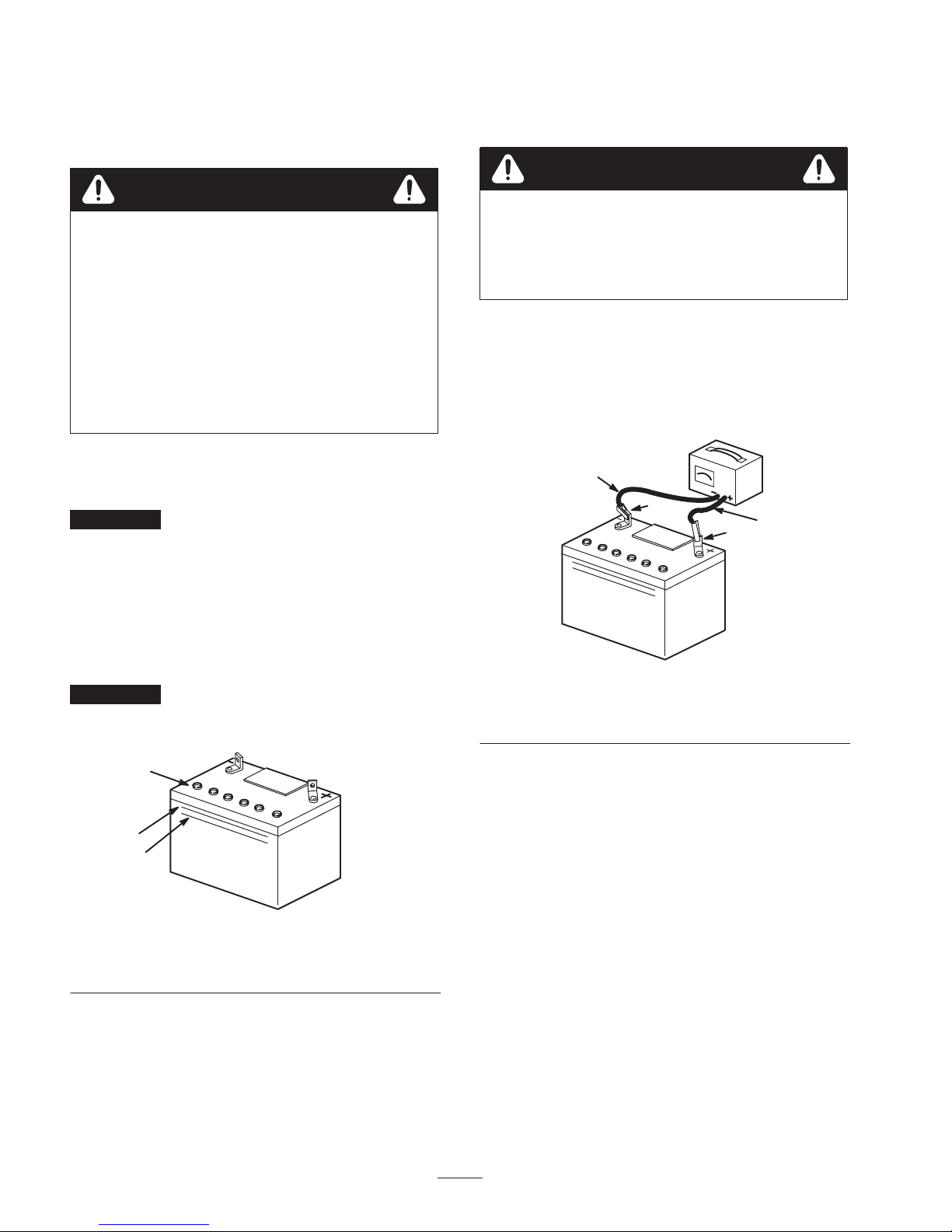
6. Charge the battery for 1 hour at 25 to 30 amps or
6 hours at 4 to 6 amps (Fig. 2). Do not overcharge the
battery.
Warning
Charging the battery produces gasses that can
explode.
Never smoke near the battery and keep sparks
and flames away from battery.
7. When the battery is fully charged, unplug the charger
from the electrical outlet, then disconnect the charger
leads from the battery posts (Fig. 2).
8. Install the battery in the tractor and connect the battery
cables; refer to the Operator’s Manual, Installing the
Battery.
4
2
3
1
2. Clean the top of the battery with a paper towel.
3. Remove the vent caps from the battery (Fig. 1). Slowly
pour electrolyte into each battery cell until the
electrolyte level is up to the Upper line on the battery
case (Fig. 1).
Important Do not overfill the battery because
electrolyte (sulfuric acid) can cause severe corrosion and
damage to the chassis.
1
2
3
m-5004
Figure 1
1. Vent caps
2. Upper line
4. Wait five to ten minutes after filling the battery cells.
Add electrolyte, if necessary, until the electrolyte level
is up to the Upper line (Fig. 1) on the battery case.
3. Lower line
Figure 2
1. Positive post
2. Negative post
3. Charger red (+) wire
4. Charger black (–) wire
Installing the Motion Control
Levers
1. Remove the 4 bolts (3/8 x 1 in.) and 4 curved washers
(3/8 in.) which attach the motion control levers to the
control arm shafts for shipping (Fig. 3).
2. Place the levers (with the mounting plates toward the
rear of the machine) on the outside of the control arm
shaft and loosely secure them with the 4 bolts and
curved washers removed in step 1 (Fig. 3).
5. Install the battery vent caps.
2
Page 3

1
2
3
1. Control ar m
2. Bolt, 3/8 x 1 in.
Figure 3
4
3. Curved washer, 3/8 in.
4. Control arm shaft
m–5215
4. Slide the shoulder bolts on the bottom of the seat into
the slots on the seat support (Fig. 5). Secure the seat to
the seat support with the flat washers and knobs
removed in step 2 (Fig. 5).
2
3
3. Position the levers so that the bolts are in the center of
the slots on the lever mounting plate and tighten the
bolts until they are snug.
4. Align the front/rear position of the levers with each
other while in the neutral position. Loosen the bolts
and adjust the levers by sliding and/or tilting the
lever(s) forward or backward until they are properly
aligned.
5. If the ends of the motion control levers hit against each
other while they are in the drive position (Fig. 4) (the
levers are rotated in as far as possible), make
adjustments by moving the levers outward to the
neutral lock position and carefully bend them outward.
Move them back to the drive position and check for
clearance. Repeat if necessary.
1
m–5579
Figure 5
1. Seat support
2. Shoulder bolt
5. Lower the seat and adjust it if necessary; refer to
Positioning the Seat in the Operator’s Manual.
3. Knob
Checking the Mower
Adjustment
The mower deck was leveled at the factory. If the mower
is not cutting level, adjust the side-to-side level and the
front-to-rear blade slope. See the Operator’s Manual for
the proper procedure.
Checking the Side Discharge
Chute
Remove the plastic tie holding the side discharge chute
up, and lower the chute into place.
Figure 4
Installing the Seat
1. Cut the plastic ties securing the seat to the machine for
shipping. Remove the seat.
2. Remove the knobs and flat washers (5/16 in.) from the
bottom of the seat.
3. Raise the seat support on the machine (Fig. 5).
Checking the Engine Oil Level
Before you start the engine and use the machine, check
the oil level in the engine crankcase; refer to Checking the
Oil Level in the Operator’s Manual.
Checking the Tire Pressure
Check the front and rear tires for proper inflation. Refer to
Tire Pressure in the Operator’s Manual for the
recommended inflation pressure.
3
Page 4

 Loading...