

Page 1
TFS Series, Toro Flow Sensor
Installation Instructions
Overview
The Toro fl ow sensors provide an accurate fl ow measurements by generating a frequency signal (pulses per second)
that is proportional to the fl ow rate. The Toro fl ow sensors are designed for below grade applications for irrigation
monitoring where the fl ow rates are between 0.5–30 ft/sec and temperatures are below 180º Fahrenheit. The
To ro fl ow sensors are supplied with two single conductor, 18 AWG solid copper wire leads with U.L. Style 116666
direct burial insulation. An internal preamplifi er allows the pulse signal to travel up to 2000’ without further signal
amplifi cation.
Models
Model Number Size Description
TFS-050 1/2” Flow Sensor, 1/2”, Plastic Tee
TFS-075 3/4” Flow Sensor, 3/4”, Plastic Tee
TFS-100 1” Flow Sensor, 1”, Plastic Tee
TFS-150 1.5” Flow Sensor, 1.5”, Plastic Tee
TFS-200 2” Flow Sensor, 2”, Plastic Tee
TFS-300 3” Flow Sensor, 3”, Plastic Tee
TFS-400 4” Flow Sensor, 4”, Plastic Tee
Controller Compatibility
The Toro fl ow sensors are compatible with the following controllers:
• Toro TMC-424 • Toro Intelli-SenseTM TIS-360/480
• Toro SentinelTM • Toro SitePro
• Irritrol MC-E • Any controller compatible with Frequency output fl ow sensor
(Pulse per Second proportional to fl ow velocity)
®
Sizing
The following table indicates the suggested fl ow range of the Toro fl ow sensors. Although the sensors will operate
above and below the indicated fl ow rates, following the suggested range will ensure the best performance from the
fl ow sensor. Sensors should be sized according to fl ow rates rather than pipe size.
Model Number
TFS-050 1.2 – 12
TFS-075 2.7 – 28
TFS-100 5 – 50
TFS-150 5 – 100
TFS-200 10 – 200
TFS-300 20 – 300
TFS-400 40 – 500
Suggested Operating
Range (Gallons / Minute)
Suggested Operating
Range (Liters / Second)
0.1 – 0.8 0.3 – 2.7
0.2 – 1.8 0.6 – 6.4
0.3 – 3.2 1.1 – 11.4
0.3 – 6.3
0.6 – 12.6
1.3 – 18.9
2.5 – 31.5
Suggested Operating
Range (Cubic Meters / Hour)
1.1 – 22.7
2.3 – 45.4
4.5 – 68.1
9.1 – 113.6
Page 2
Flow Sensor to Pipeline Installation
The accuracy of the fl ow sensor’s measurement is highly dependent on proper sensor location within the piping
system. Irregular fl ow velocity caused by valves, fi ttings, pipe bends, etc. can lead to inaccurate fl ow rate
measurements even though local fl ow velocity measurements may be accurate. A sensor located in the pipe
where it can be affected by air bubbles, fl oating debris, or sediment may not achieve full accuracy and could be
damaged. The Toro fl ow sensors are designed to operate reliably even under adverse conditions but following
recommendations will ensure maximum system accuracy.
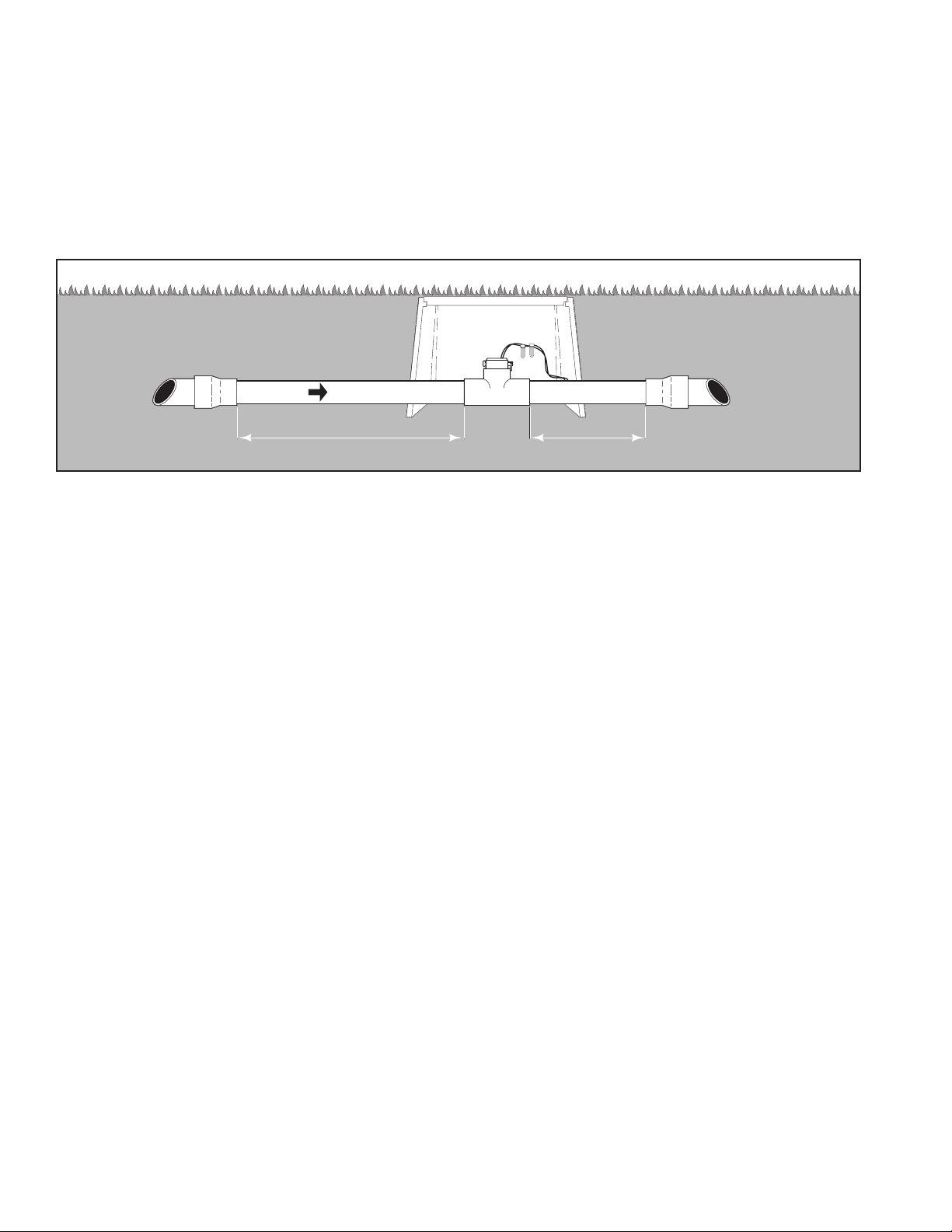
Select a location along the pipe system that is 10 times the pipe diameter upstream and 5 times the pipe diameter
downstream to minimize fl ow disturbance. Pipe bends, valves, pipe fi ttings, pipe enlargements and reductions
should not be present within this pipe length.
Flow
10 X Pipe Diameter 5 X Pipe Diameter
Note: For 1.5” and larger fl ow sensors, install according to the fl ow direction shown by the arrow on the tee. For 1.0”
and smaller fl ow sensors, installation is not dependent on fl ow direction.
Flow Sensor to Pipeline Installation
Step 1 - Remove the sensor from the tee.
a. For 1.5” and larger Sensors: Pull the clevis pin that retains the fl ow sensor to the tee,
then carefully remove it from the tee.
b. For 1.0” and smaller Sensors: Unscrew the sensor cap from the tee by turning it counterclockwise.
Carefully pull the sensor out from the tee.
Step 2 - Properly clean the pipe ends and tee socket.
Step 3 - Use solvent cement to secure the pipes to the tee.
Step 4 - Reinstall the sensor to the tee as follows:
a. For 1.5” and larger Sensors:
i. Align the fl ow arrow on top of the sensor housing to the direction of the fl ow.
ii. Carefully press the sensor straight into the tee.
iii. Install the clevis pin through the tee and sensor.
iiii. Install the cotter ring into the clevis pin.
b. For 1.0” and smaller Sensors:
i. Carefully line up the guide pin on the sensor to the slot on the tee.
ii. Carefully press the sensor straight into the tee.
iii. Screw the sensor cap fi rmly onto the tee.
Note: Hand tighten the sensor only.
Step 5 - Complete the wiring connections.
Page 3

Cable Installation
Step 1 - Use a twisted pair cable suitable for direct burial
to connect the sensor to the controller. Multi-pair
telecommunication cable or direct burial cables may
be used. Shielded cable is recommended. Connect
the cable wires to the sensor wires.
Step 2 - Waterproof the splices. Two part epoxy
waterproofi ng kits or waterproof wire connectors
are recommended.
Step 3 - Route the cable from the sensor to the controller.
The cable may be extended up to 2000’ if using a
2-conductor shielded 18 AWG or larger stranded
copper wire with appropriate ratings. Be sure to
leave enough fl exibility in the cable for future sensor
servicing.
Step 4 - When connecting to a Toro controller, connect the red wire to “IN”, “SIGNAL” or “(+)” terminal and the black
wire to “GND”, “SIGNAL”, “(–)” or “COM” terminal.
Example: Sensor
Connection to TMC-424
Red Wire
connect to
Controller
Sensor (+)
TSM-4F
Module
Black Wire
connect to
Controller
Sensor (–)
Calibration Tables
For controllers displaying Flow Rate (GPM, etc.), the Toro fl ow sensor use a unique K and Offset numbers for
calibration. The Calibration Table below provides the calibration data for each of the Toro fl ow sensors when installed
in SCH 40 piping.
Model Number Size Description
TFS-050 1/2” Flow Sensor, 1/2”, Plastic Tee
TFS-075 3/4” Flow Sensor, 3/4”, Plastic Tee
TFS-100 1” Flow Sensor, 1”, Plastic Tee
TFS-150 1.5” Flow Sensor, 1.5”, Plastic Tee
TFS-200 2” Flow Sensor, 2”, Plastic Tee
TFS-300 3” Flow Sensor, 3”, Plastic Tee
TFS-400 4”
K Value
0.07800
0.15630
0.26112
1.69900
2.84290
8.30900
13.74283
Offset
0.9
0.9
1.2
-0.31600
0.14350
0.22700
0.23707Flow Sensor, 4”, Plastic Tee
Troubleshooting
Step 1 - If the voltage at the sensor input is less than 7 VDC during “NO Flow” situation, disconnect the sensor
from the sensor terminals. Re-measure the voltage at the sensor terminals. The voltage reading should
be between 8–20 VDC. If the voltage at the sensor terminals is still below 7 VDC, the controller may be
the cause of the problem (hardware or fi rmware). If the proper voltage is present at the sensor terminals,
proceed to Step 2.
Step 2 - If you suspect that the sensor is defective, test the controller’s circuitry by connecting a wire to one of the
sensor terminal. Use the other end of the wire to short the other sensor terminal repeatedly to simulate
a fl ow signal. Depending on the controller, you night be required to continue this for a few seconds
for the controller to register a reading. If the display do not show a fl ow reading, it indicates a problem
with the controller. If the controller does register a fl ow reading, then the defect might be between the
communication cable and the sensor. Proceed to Step 3.
Step 3 - Test the cable for continuity. Disconnect the splices from the sensor and connect the cable wires together.
Take the cable wires at the controller side and test for continuity. Use a volt meter with a continuity tester. If
the volt meter indicates good continuation in the cable, then the cable is not defective, continue to Step 4.
If the cable indicates no continuation, then a break in the circuit is present within the cable. If there are any
splices in the cable, check and re-secure it. Check the cable’s continuity again. Replace the cable if you still
detect a continuity break.
Step 4 - Drain the pipe line and verify that the pressure is relieved. Remove the sensor from the tee (See Flow
Sensor to Pipeline Installation, Step 1). If the sensor has been disconnected from the controller,
reconnect it to test. Spin the impeller by hand. If the controller detects a fl ow and the impeller spins freely,
then the fl ow rate may have been below our design minimum or the pipeline system is full of air pockets. If
the sensor fails to send a fl ow signal when the impeller is spinning, then the sensor is defective. Replace the
sensor.
Page 4

© 2007 The Toro Company • Irrigation Division • www.toro.com Part Number 373-0429 Rev. A
 Loading...