

Page 1

TC3, 4, 5000 GAS TRIMMER, MODELS 51643, 51644, 51645
Table of Contents – Page 1 of 4
ABOUT THIS MANUAL
SAFETY INFORMATION
FOR YOUR SAFETY...
SPECIFICATION
TOOL REQUIREMENTS:
TROUBLESHOOTING
MAINTENANCE
MAINTENANCE - AIR CLEANER
MAINTENANCE - MUFFLER
MAINTENANCE - SPARK PLUG
MAINTENANCE - FUEL FILTER
MAINTENANCE - COOLING SYSTEM
MAINTENANCE - TRIMMER IMPLEMENT
MAINTENANCE - PREPARATION FOR STORAGE
MAINTENANCE - GEARBOX LUBRICATION
SECTION 1 CARBURETOR
CARBURETOR OPERATION
CARBURETOR OPERATION - THE DIAPHRAGM PUMP
CARBURETOR OPERATION - FUEL METERING & MIXING
CARBURETOR OPERATION - THE PRIMER SYSTEM
CARBURETOR - REMOVAL
CARBURETOR - DISASSEMBLY
CARBURETOR - REASSEMBLY
CARBURETOR - INSTALLATION
CARBURETOR ADJUSTMENT - IDLE SPEED
CARBURETOR ADJUSTMENT - MIXTURE
CARBURETOR ADJUSTMENT - THROTTLE VALVE
SECTION 2 FUEL SYSTEM
FUEL TANK - FUEL TANK - REMOVAL
FUEL TANK - INSTALLATION
PRIMER PUMP - PRIMER PUMP - PROPER USE
PRIMER PUMP - OPERATION
PRIMER PUMP - DISASSEMBLY
PRIMER PUMP - INSPECTION
PRIMER PUMP - REASSEMBLY
FUEL PICKUP TUBE AND FILTER - SERVICE
FUEL CAP - FUEL CAP - OPERATION
Page 2

TC3, 4, 5000 GAS TRIMMER, MODELS 51643, 51644, 51645
Table of Contents – Page 2 of 4
SECTION 2 FUEL SYSTEM - Continued
FUEL CAP - DISASSEMBLY
FUEL CAP - INSPECTION
FUEL CAP - REASSEMBLY
SECTION 3 IGNITION
IGNITION OPERATION
IGNITION OPERATION - FLYWHEEL
IGNITION OPERATION - IGNITION COIL
IGNITION OPERATION - TRIGGER MODULE
IGNITION OPERATION - SPARK PLUG
AIR GAP ADJUSTMENT
TC3000/TC4000 AIR GAP ADJUSTMENT - PREPARATION
TC3000/TC4000 AIR GAP ADJUSTMENT
TC3000/TC4000 AIR GAP ADJUSTMENT - REASSEMBLY
TC5000 AIR GAP ADJUSTMENT - PREPARATION
TC5000 AIR GAP ADJUSTM ENT
TC5000 AIR GAP ADJUSTMENT - REASSEMBLY
COIL - COIL - REMOVAL
COIL - INSTALLATION
SECTION 4 RECOIL STARTER
RECOIL STARTER - OPERATION
RECOIL MECHANISM - REMOVAL
RECOIL MECHANISM - DISASSEMBLY
RECOIL MECHANISM - REASSEMBLY
RECOIL MECHANISM - INSTALLATION
STARTER PULLEY - REMOVAL
STARTER PULLEY - INSTALLATION
SECTION 5 CLUTCH SHOES AND FLYWHEEL
CLUTCH SHOES AND FLYWHEEL - OPERATION
CLUTCH SHOES AND FLYWHEEL - DISASSEMBLY
CLUTCH SHOES AND FLYWHEEL - INSPECTION
CLUTCH SHOES AND FLYWHEEL - REMOVAL
CLUTCH SHOES AND FLYWHEEL - REASSEMBLY
CLUTCH DRUM AND CLUTCH HOUSING - CLUTCH DRUM AND CLUTCH HOUSING -
CLUTCH DRUM AND CLUTCH HOUSING - REASSEMBLY
ISOLATION MOUNT (TC4000 AND TC5000 ONLY) - ISOLATION MOUNT -
ISOLATION MOUNT - DISASSEMBLY
ISOLATION MOUNT - REASSEMBLY
SECTION 6 ENGINE
ENGINE - OPERATION
ENGINE - REMOVAL FROM DRIVE TUBE
Page 3

TC3, 4, 5000 GAS TRIMMER, MODELS 51643, 51644, 51645
Table of Contents – Page 3 of 4
SECTION 6 ENGINE - Continued
ENGINE - DISASSEMBLY
ENGINE - CLEANING AFTER DISASSEMBLY
ENGINE - INSPECTION
ENGINE - REASSEMBLY
ENGINE - INSTALLATION ON DRIVE TUBE
SECTION 7 CONTROLS
CONTROL - DISASSEMBLY
CONTROL - REASSEMBLY
GRIP - REMOVAL
GRIP - INSTALLATION
SECTION 8 HANDLE
TC3000 HANDLE - REMOVAL FROM DRIVE TUBE
TC3000 HANDLE - INSTALLATION ON DRIVE TUBE
TC3000 HANDLE - ADJUSTMENT
TC4000 HANDLE - REMOVAL FROM TUBE
TC4000 HANDLE - INSTALLATION ON DRIVE TUBE
TC4000 HANDLE - ADJUSTMENT
TC5000 HANDLE - REMOVAL FROM DRIVE TUBE.
TC5000 HANDLE - INSTALLATION ON DRIVE TUBE
TC5000 HANDLE - ADJUSTMENT
SECTION 9 SHIELD
SHIELD - REMOVAL FROM DRIVE TUBE
SHIELD - INSTALLATION ON DRIVE TUBE
SHIELD - MOUNTING CUTTER KNIFE ON SHIELD
SECTION 10 GEARBOX
GEARBOX - REMOVAL
GEARBOX - INSTALLATION ON DRIVE TUBE
GEARBOX - SEAL REMOVAL
GEARBOX - SEAL INSTALLATION
SECTION 11 DRIVE SHAFT AND TUBE
DRIVE SHAFT - DRIVE SHAFT - REMOVAL
DRIVE SHAFT - INSTALLATION
DRIVE TUBE - DRIVE TUBE - REMOVAL
DRIVE TUBE - INSTALLATION
SECTION 12 LEECO MANUAL FEED HEAD
LEECO MANUAL FEED HEAD - SPOOL REMOVAL
LEECO MANUAL FEED HEAD - LINE REPLACEMENT
LEECO MANUAL FEED HEAD - SPOOL INSTALLATION
Page 4

TC3, 4, 5000 GAS TRIMMER, MODELS 51643, 51644, 51645
Table of Contents – Page 4 of 4
SECTION 12 LEECO MANUAL FEED HEAD - Continued
LEECO MANUAL FEED HEAD - DISASSEMBLY
LEECO MANUAL FEED HEAD - INSPECTION
LEECO MANUAL FEED HEAD - REASSEMBLY
SECTION 13 KAAZ MANUAL FEED HEAD
KAAZ MANUAL FEED HEAD - DISASSEMBLY
KAAZ MANUAL FEED HEAD - LINE REPLACEMENT
KAAZ MANUAL FEED HEAD - REASSEMBLY
SECTION 14 PLASTIC FIXED LINE HEAD
PLASTIC FIXED LINE HEAD - LINE REPLACEMENT
PLASTIC FIXED LINE HEAD - REMOVAL
SECTION 15 METAL FIXED LINE HEAD
METAL FIXED LINE HEAD - LINE REPLACEMENT
METAL FIXED LINE HEAD - REMOVAL
METAL FIXED LINE HEAD - INSTALLATION
SECTION 16 TAP AND TRIM HEAD
TAP AND TRIM LINE REPLACEMENT - TAP AND TRIM SPOOL -
TAP AND TRIM SPOOL - LINE REPLACEMENT
TAP AND TRIM SPOOL - INSTALLATION
TAP AND TRIM HEAD - DISASSEMBLY
TAP AND TRIM HEAD - INSPECTION
TAP AND TRIM HEAD - REASSEMBLY
SECTION 17 METAL BLADES
METAL BLADE - REMOVAL
METAL BLADE - INSTALLATION
SECTION 18 HARNESSES
STANDARD AND DELUXE HARNESS - ASSEMBLY
SECTION 19 SPARK ARREST O R MUFFL ER
SPARK ARRESTOR MUFFLER - REMOVAL
SPARK ARRESTOR MUFFLER - INSTALLATION
SPARK ARRESTOR MUFFLER - MAINTENANCE
Page 5
Page 6
ABOUT
This Service Manual was written expressly for the Tor0 TC3000, TC4000 and
TC5000 Gas Powered Trimmers. The Tor0 Company had made every effort to
make the information
in
this manual complete and correct.
THIS
MANUAL
This manual was written with the service technician
that information used most often is
information on safety, maintenance, specifications, special tools and
troubleshooting all
Disassembly, inspection and reassembly procedures are covered
two-thirds of the manual and are grouped by component. We tried to cover each
common repair with its own section or sub-section. For example, you will find
that air gap adjustment and ignition coil replacement are called out separately.
And, because certain components are often difficult to troubleshoot without a
good
understanding of how they work, we have included some component theory.
This information can be found of the beginning of most service procedure
sections.
We are hopeful that you will find this manual a valuable addition to your shop. If
you should come across any errors or if you have any questions regarding this
manual, please contact us at the following address:
in
the front third of
81
11
Bloomington, MN, USA 55420
up
front. As a result, you will find reference
the
manual.
The Tor0 Company
Lyndale Avenue South
in
mind.
It
is organized
in
so
the last
The Tor0 Company reserves the right to change product specifications or this
manual without notice.
The Tor0 Company gratefully acknowledges the assistance of Mitsubishi Heavy
Industries, Ltd.
in
the production of this manual.
COPYRIGHT@ ALL RIGHTS RESERVED
(C)
The Toro Company
MINNEAPOLIS,
MN
1987
55420 -USA
Page 7
Reference Information
Safety Information
Specifications 2
Tool Requirements
TABLE OF CONTENTS
Page
1
5
Service Procedures
Section
Section 2 Fuel System
1
Troubleshooting
Maintenance
Carburetor Page
operation 11
removal
disassembly 14
reassembly 16
installation 18
adjustment 18
Fuel Tank
removal 20
installation 20
6
8
14
Primer Pump
properuse 21
operation
disassembly 22
inspection 22
reassembly 22
Fuel Pickup Tube and Filter
service 23
Fuel Cap
operation 23
disassembly 24
inspection 24
reassembly 24
21
Page 8

Service Procedures (cont'd)
TABLE
OF
CONTENTS
Page
Section
5
operation
airgapadjustment
coilremoval
coil installation
Recoil Starter
Recoil Mechanism
operation
removal
disassembly
reassembly
installation
Starter Pulley
removal
installation
Clutch and lsomount
Clutch Shoes and Flywheel
operation
disassembly
inspection
25
27
28
29
30
30
30
31
32
33
33
34
34
34
Section
6
removal
reassembly
Clutch Drum and Housing
disassembly
reassembly
lsomount
Engine
(TC4000
operation
disassembly
reassembly
operation
removal
disassembly
cleaning after disassembly
inspection
and TC5000 only)
from
drive tube
35
35
35
35
36
37
37
38
40
41
42
43
Page 9

Service Procedures (cont’d)
Section 6 Engine (cont’d)) Page
TABLE
OF
CONTENTS
Section
Section
8
7
reassembly
installation on drive tube.
Control and Grip
Control
disassembly 46
reassembly
Grip
removal
installation
Handle
TC3000
removal from drive tube 48
Installation on drive tube. 48
adjustment
TC4000
removal from drive tube
installation on drive tube.
adjustment.
44
45
48
48
49
Section
Section
9
10
TC5000
removal from drive tube
installation on drive tube.
adjustment.
Shield
removal from drive tube
installation on drive tube.
mounting cutter knife on shield
Gearbox
removal from drive tube
installation on drive tube.
sealremoval
sealinstallation
49
50
50
52
52
53
54
54
Page 10
Service Procedures (cont’d)
Drive Shaft
Drive
TABLE
removal 56
installation 56
Tube
removal 56
installation 57
OF
CONTENTS
Section
Section
Section 14 Plastic Fixed Line Head
12
13
Leeco@ Manual Line Feed Head
sped
removal 58
linereplacement 58
installation 58
Head
disassembly 59
inspection 59
reassembly 59
Kaaz@ Manual Line Feed Head
head disassembly 61
linereplacement 61
headreassembly 62
linereplacement
headremoval 63
headinstallation 64
63
Section 15 Metal Fixed Line Head
linereplacement
headremoval
headinstallation
Section 16 Tap and Trim@ Head
Spool
removal 67
linereplacement 67
installation 67
65
65
66
Page 11
Service Procedures (cont’d)
TABLE
OF
CONTENTS
Section
Section 17
Section 18
Section 19
Tap and Trim@ Head (cont’d)
Head
disassembly 68
inspection 68
reassembly 68
Metal Blades
removal 69
installation 69
Harnesses
assembly
Spark Arrestor Muffler
removal 71
installation 71
maintenance 71
Page 16
70
Page 12
SAFETY INFORMATION
This manual is intended
this safety symbol manual only. The safety instructions provided
means WARNING
CAUTION product only. The individual Operator’s Manual will
A
INSTRUCTION Read the instruction TC3000.
because
Failure to comply with the instruction
may result
PERSONAL SAFETY contain safety information on the operation of the
it
has to do
in
personal injury
with
or
FOR
or
safety.
death.
YOUR SAFE
manual are for the troubleshooting and service of the
Operator’s Manuals with complete operational safety
instructions are available through:
as
TC4000.
Minneapolis,
or TC5000.
The Tor0 Company
Publications Department
81
11
Lyndale Avenue South
MN
TY...
a service and repair
55430
U.S.A.
in
this
I----
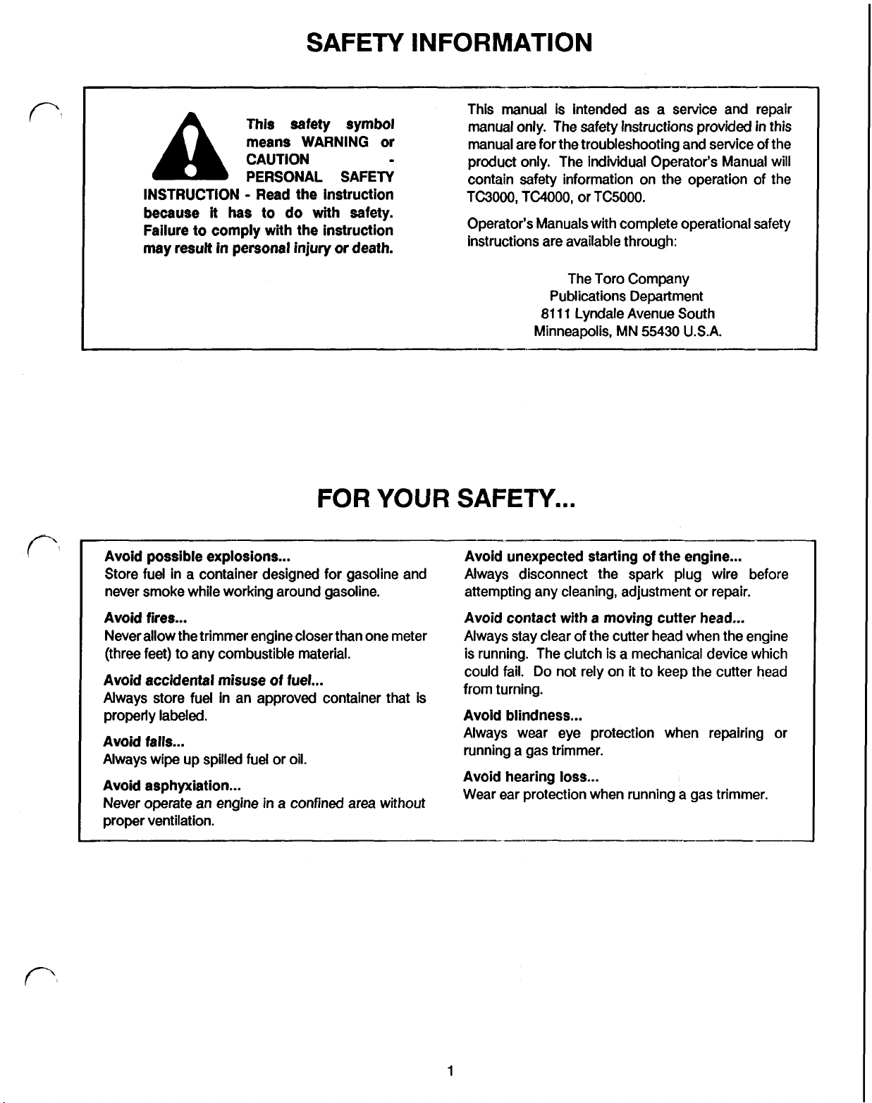
Avoid possible explosions Avoid unexpected starting of the engine
Store fuel in a container designed for gasoline and Always disconnect the spark plug wire before
never smoke while working around gasoline. attempting any cleaning, adjustment or repair.
Avoid fires Avoid contact with a moving cutter head
Never allow the trimmer engine closer than one meter Always stay clear of the cutter head when the engine
(three feet) to any combustible material. is running. The clutch is a mechanical device which
Avoid accidental misuse of fuel
Always store fuel in an approved container that is
properly labeled.
Avoid falls
Always wipe up spilled fuel or oil.
Avoid asphyxiation
Never operate an engine
proper ventilation.
in
a confined area without
could fail. Do not rely on
from turning.
Avoid blindness
Always wear eye protection when repairing or
running a gas trimmer.
Avoid hearing
Wear ear protection when running a gas trimmer.
loss
it
to keep the cutter head
1
Page 13
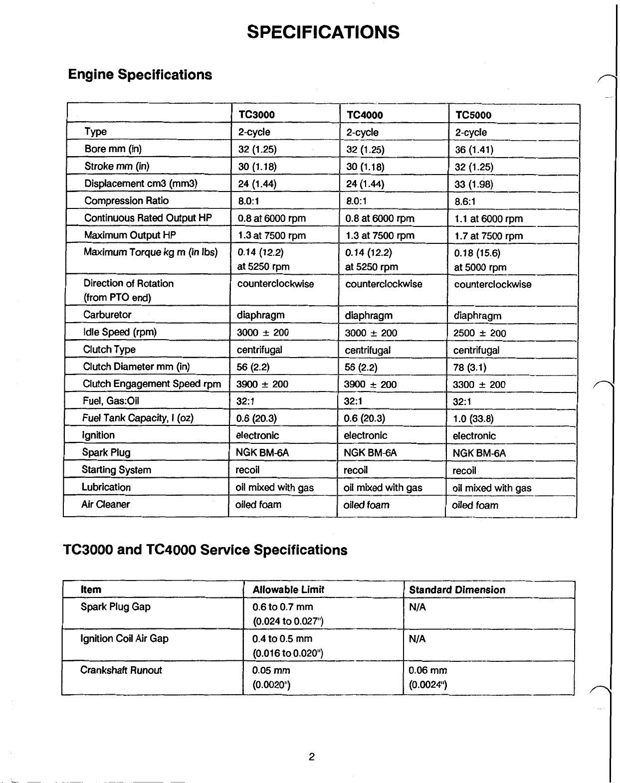
Engine Specifications
SPECIFICATIONS
TC3000
and
TC4000
Service Specifications
2
Page 14
SPECIFICATIONS
(cont'd)
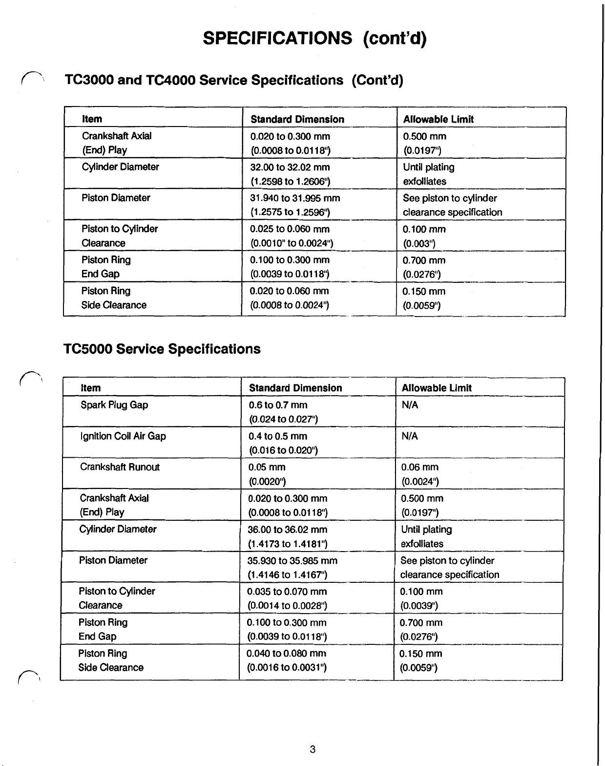
TC3000 and TC4000 Service Specifications (Cont'd)
Piston Ring
Side
Clearance
0.020
(0.0008
TC5000 Service Specifications
to
to
0.060
0.0024")
mm
0.150
mm
.
(0.0059")
3
Page 15
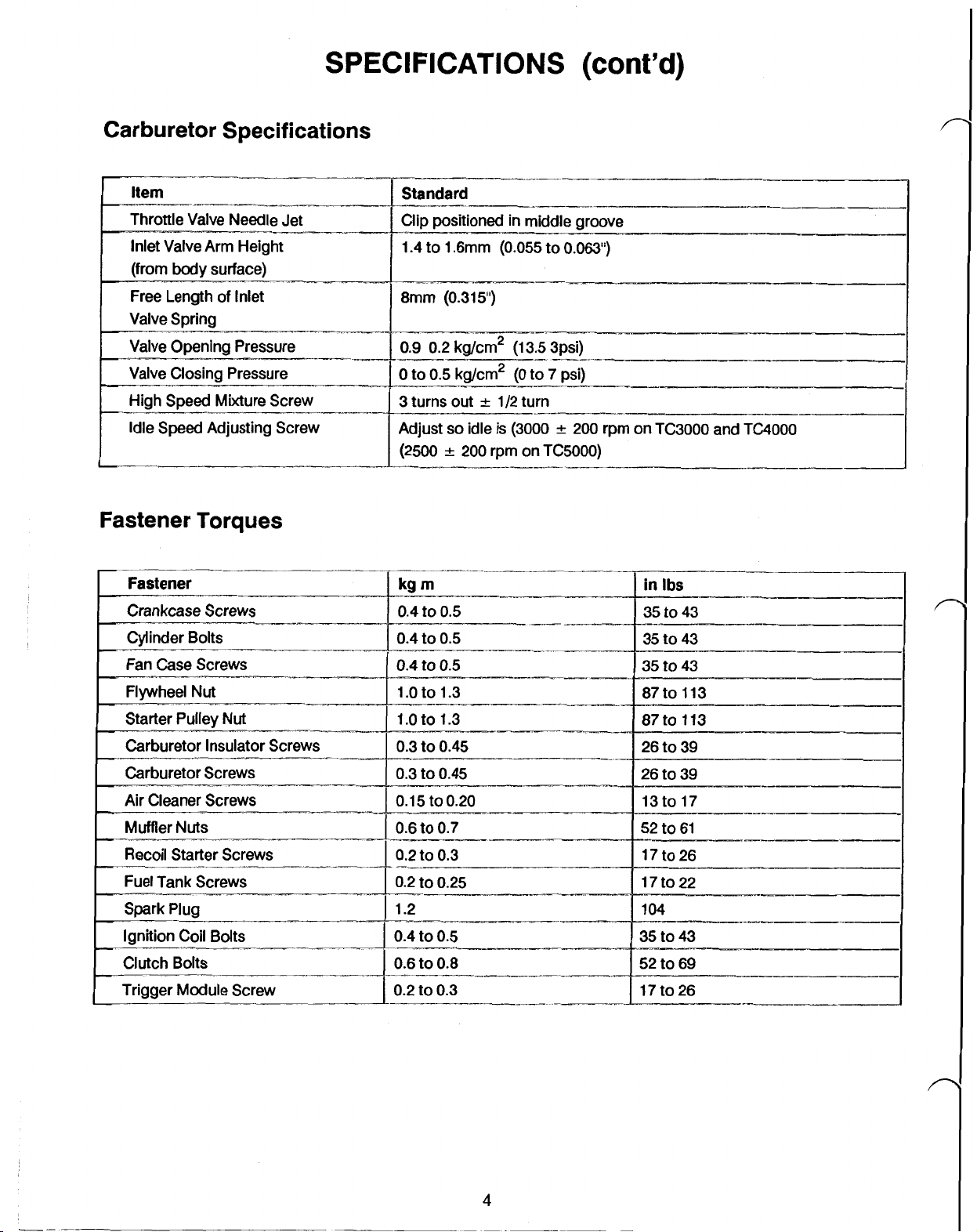
SPECIFICATIONS
Carburetor Specifications
Item Standard
Throttle Valve Needle Jet
1.4
to 1.6mm
(0.055
(cont'd)
to
0.W')
Idle Speed Adjusting Screw Adjust
Fastener Torques
Fastener
Crankcase Screws
(2500
kgm
0.4
to
so
0.5
idle
200
is
rpm
(3000
on
200
TCSOOO)
rpm on TC3000 and
in
Ibs
35 to 43
TC4000
Page 16
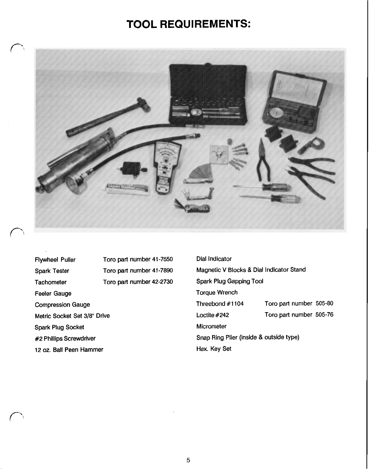
TOOL
REQUIREMENTS:
Flywheel Puller Tor0 part number 41-7650 Dial Indicator
V
Spark Tester Tor0 part number41-7890
Tachometer
Feeler Gauge
Compression Gauge
Metric Socket Set
Spark Plug Socket
#2 Phillips Screwdriver
12
oz.
Ball Peen Hammer
3/8”
Tor0
Drive
part number 42-2730
Magnetic
Spark Plug Gapping
Torque Wrench
Threebond #1104 Tor0 part number
Loctite #242 Tor0 part number
Micrometer
Snap Ring Plier (inside
Hex. Key Set
Blocks & Dial Indicator Stand
Tool
&
outside type)
505-80
505-76
5
Page 17
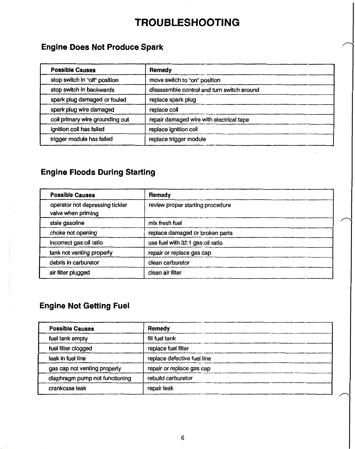
TROUBLESHOOTING
Engine Does Not Produce Spark
Engine
Floods
During Starting
Engine Not Getting Fuel
crankcase
leak
Page 18
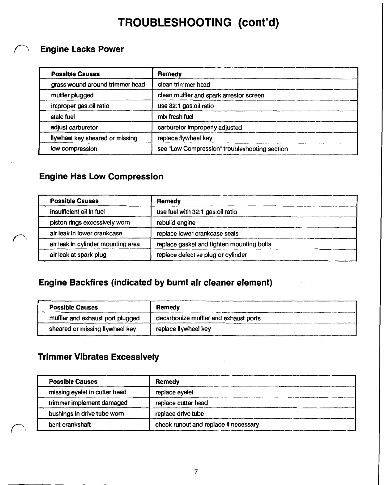
TROUBLESHOOTING
Engine Lacks Power
Engine Has Low Compression
(cont’d)
Remedy
Engine Backfires (indicated by burnt air cleaner element)
Trimmer Vibrates Excessively
I
7
Page 19
Maintenance
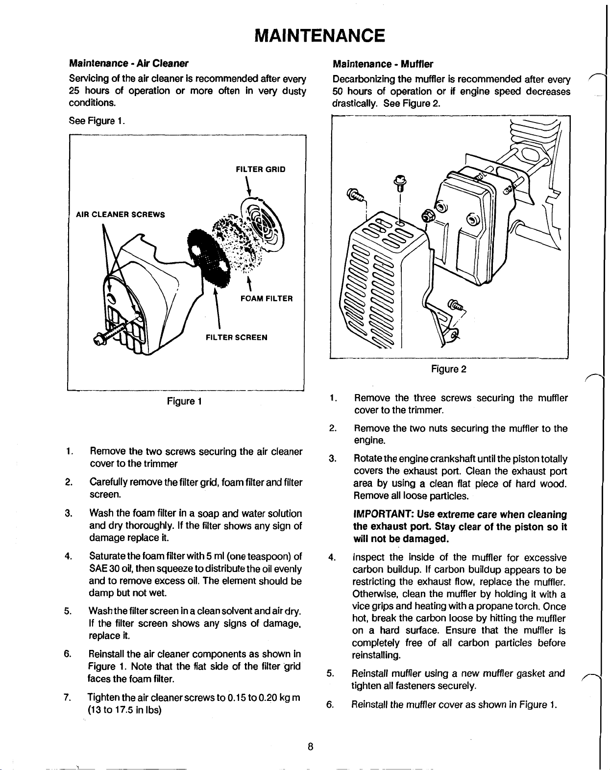
Air
Cleaner
Servicing of the air cleaner is recommended after every
25
hours of operation or more often in very dusty
conditions.
See
Figure
1.
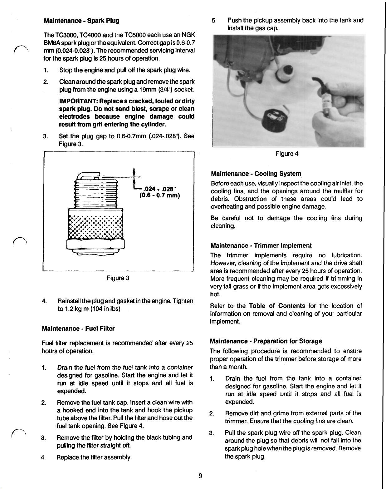
Maintenance Muffler
Decarbonizing the muffler is recommended after every
50
hours of operation or
drastically. See Figure
if
engine speed decreases
2.
AIR
1.
Remove the
FILTER
FILTER SCREEN
Figure
two
screws securing the air cleaner
1
GRID
FOAM FILTER
cover to the trimmer
Carefully remove the filter grid, foam filter and filter
2.
screen.
Figure
1.
Remove the three screws securing the muffler
2
cover to the trimmer.
2.
Remove the
two
nuts securing the muffler to the
engine.
3.
Rotate the engine crankshaft until the piston totally
covers the exhaust port. Clean the exhaust port
area by using a clean flat piece of hard wood.
Remove all loose particles.
Wash the foam filter in a soap and water solution
3.
and dry thoroughly.
damage replace
4.
Saturate the foam filter with 5ml (one teaspoon) of
SAE
30
oil, then squeeze to distribute the oil evenly
If
the filter shows any sign of
it.
and to remove excess oil. The element should be
damp but not wet.
Wash the filter screen in a clean solvent and air dry.
5.
If
the filter screen shows any signs of damage,
replace
Reinstall the air cleaner components as shown in
6.
Figure
it.
1.
Note that the flat side of the filter grid
faces the foam filter.
Tighten the air cleaner screws to
7.
(13
to
17.5
in Ibs)
0.15
to
0.20
kg m
8
IMPORTANT
the exhaust port. Stay clear
will
not be damaged.
4.
Inspect the inside of the muffler for excessive
carbon buildup.
Use extreme care
If
carbon buildup appears to be
when
of
the piston
cleaning
restricting the exhaust flow, replace the muffler.
Otherwise, clean the muffler by holding
it
vice grips and heating with a propane torch. Once
hot, break the carbon loose by hitting the muffler
on
a
hard surface. Ensure that the muffler is
completely free
of
all carbon particles before
reinstalling.
5.
Reinstall muffler using a new muffler gasket and
tighten all fasteners securely.
6.
Reinstall
the
muffler cover as shown in Figure
so
with a
1.
it
Page 20
Maintenance Spark Plug
The TC3000,
BMGA spark plug or the equivalent. Correct gap is
mm
(0.024-0.028”).
for the spark plug is
1.
Stop the engine and pull
2.
Clean around the spark plug and remove the spark
plug from
IMPORTANT: Replace
spark plug.
TC4000
and the TC5000 each use an
The recommended servicing interval
25
hours of operation.
off
the spark plug wire.
the
engine using a 19mm
a
cracked, fouled or dirty
Do
not sand blast, scrape or clean
(3/4")
NGK
0.6-0.7
socket.
electrodes because engine damage could
result
from
grit entering the cylinder.
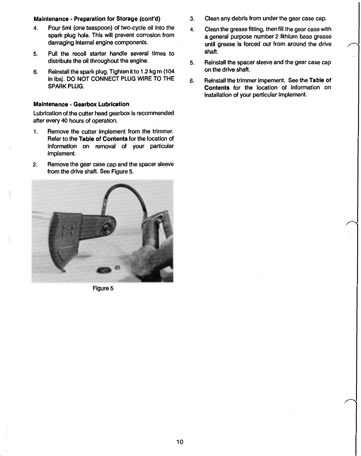
3.
Set the plug gap to 0.6-0.7mm
Figure
3.
I3
(.024-.028”)
.024
(0.6
0.7
See
.028"
mm)
5.
Push the pickup assembly back into the tank and
install the gas cap.
Figure
4
Maintenance Cooling System
Before each use, visually inspect the cooling air inlet, the
cooling fins, and the openings around the muffler for
debris. Obstruction of these areas could lead
to
overheating and possible engine damage.
Figure
Reinstall the plug and gasket in the engine. Tighten
4.
to
1.2
kg m
(1
04
in Ibs)
3
Maintenance Fuel Filter
Fuel filter replacement is recommended after every
hours of operation.
1. Drain the fuel from the fuel tank into a container
designed for gasoline. Start the engine and
run at idle speed until
it
stops and all fuel is
expended.
2.
Remove the fuel tank cap. Insert a clean wire with
a
hooked end into the tank and hook the pickup
tube above the filter. Pull the filter and hose
fuel tank opening. See Figure
3.
Remove the filter by holding the black tubing and
pulling the filter straight
4.
Replace the filter assembly.
4.
off.
out
let
the
25
to
Be careful not
damage the cooling fins during
cleaning.
Maintenance Trimmer Implement
The trimmer implements require no lubrication.
However, cleaning of the implement and the drive shaft
area is recommended after every
More frequent cleaning may be required
very tall grass or
if
the implement area gets excessively
25
hours of operation.
if
trimming in
hot.
to
the
Refer
Table
of
Contents for the location of
information on removal and cleaning of your particular
implement.
Maintenance Preparation
for
Storage
The following procedure is recommended to ensure
proper operation of the trimmer before storage of more
than a month.
it
1.
Drain
the
fuel from the tank into a container
designed for gasoline. Start the engine and
run at idle speed until
it
stops and all fuel
let
it
is
expended.
2.
Remove dirt and grime from external parts of the
trimmer. Ensure that the cooling fins are clean.
3.
Pull
the spark plug wire off the spark plug. Clean
so
around the plug
that debris will not fall into the
sparkplug hole when the plug is removed. Remove
the spark plug.
9
Page 21
Maintenance Preparation for Storage (cont’d)
4.
Pour 5ml (one teaspoon) of two-cycle oil into the
spark plug hole This will prevent corrosion from
damaging internal engine components.
5. Pull the recoil starter handle several times to
distribute the oil throughout the engine.
6.
Reinstall
in Ibs).
the
spark plug. Tighten
DO
NOT CONNECT
it
PLUG
to
WIRE
1.2
kg m
TO
(104
THE
SPARK PLUG.
Maintenance Gearbox Lubrication
Lubrication of
after every
1.
Remove the cutter implement from the trimmer.
Refer to the Table
the
cutter head gearbox is recommended
40
hours of operation.
of
Contents for the location of
information on removal of your particular
implement.
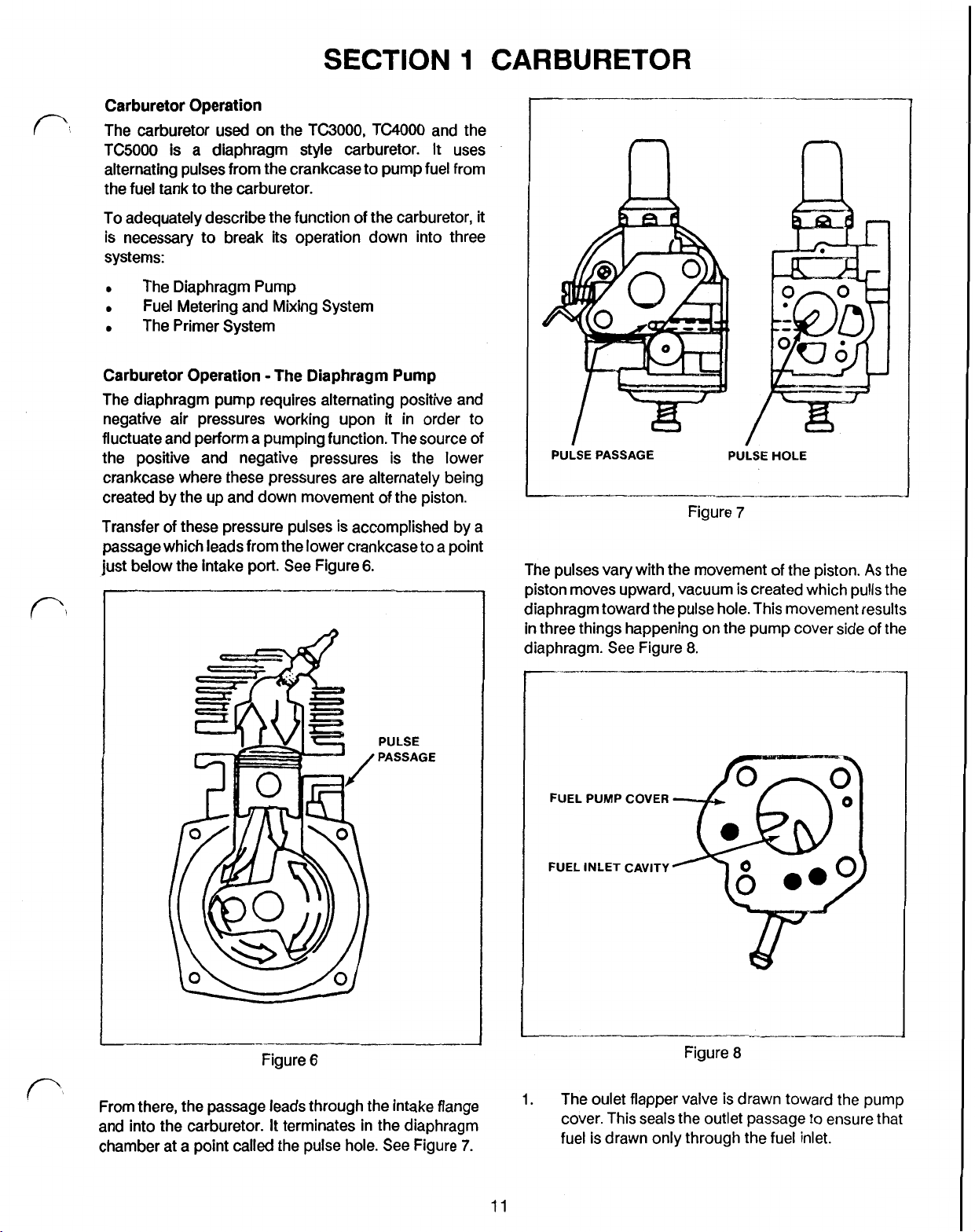
2.
Remove the gear case cap and the spacer sleeve
from the drive shaft. See Figure
5.
3.
Clean any debris from under the gear case cap.
4.
Clean the grease fitting, then fill
a general purpose number
the
2
lithium base grease
until grease is forced out from around the drive
Shaft.
5. Reinstall the spacer sleeve and
the
on the drive shaft.
6.
Reinstall the trimmer implement See the Table
Contents for the location of information on
installation of your particular implement.
gear case with
gear case cap
of
Figure
5
10
Page 22
SECTION
Carburetor Operation
The carburetor used on the TC3000, TC4000 and the
TC5000 is a diaphragm style carburetor.
alternating pulses from the crankcase to pump fuel from
the fuel tank to the carburetor.
It
1
uses
CARBURETOR
n
To adequately describe the function
is necessary to break its operation down into three
systems:
The Diaphragm Pump
Fuel Metering and Mixing System
The Primer System
Carburetor Operation The Diaphragm Pump
The diaphragm pump requires alternating positive and
negative air pressures working upon
fluctuate and perform a pumping function. The source of
the positive and negative pressures is the lower
crankcase where these pressures are alternately being
created by the up and down movement of the piston.
Transfer of these pressure pulses is accomplished by a
passage which leads from the lower crankcase to a point
just below the intake port. See Figure
of
the carburetor,
it
in order to
6.
it
PULSE PASSAGE
The pulses vary with the movement of the piston.
piston moves upward, vacuum is created which pulls the
diaphragm toward the pulse hole. This movement results
in
three things happening on the pump cover side of the
diaphragm. See Figure
Figure
8.
PULSE
7
HOLE
As
the
PULSE
PASSAGE
Figure
From there, the passage leads through the intake flange
and into the carburetor. It terminates in the diaphragm
chamber at a point called the pulse hole. See Figure
6
7.
FUEL
PUMP
COVER
FUEL
INLET
CAVITY
Figure
8
1.
The oulet flapper valve
cover. This seals the outlet passage to ensure that
fuel is drawn only through the fuel inlet.
is
drawn toward the pump
11
Page 23
Carburetor Operation
The
Diaphragm Pump
(cont’d)
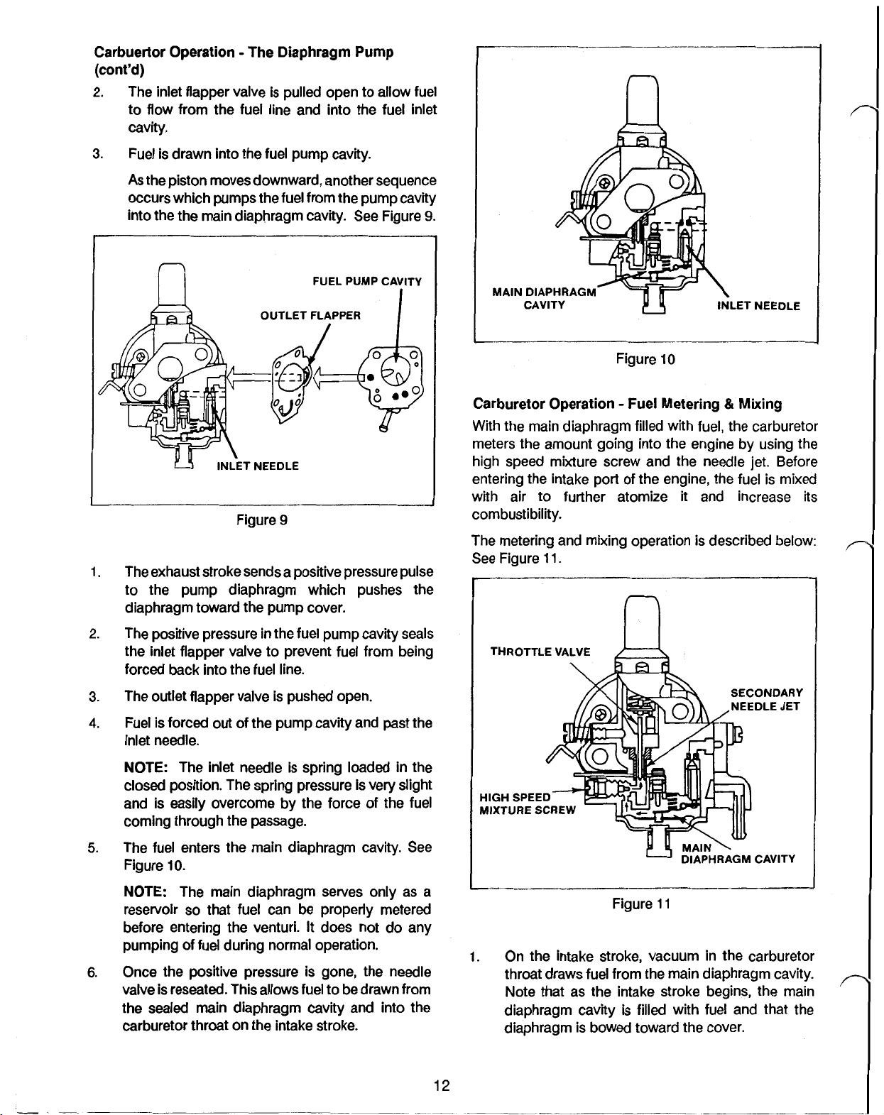
2.
The inlet flapper valve is pulled open to allow fuel
to flow from the fuel line and into the fuel inlet
cavity.
3.
Fuel is drawn into the fuel pump cavity.
As
the piston moves downward, another sequence
occurs which pumps the fuel from the pump cavity
into
the
the main diaphragm cavity. See Figure
9.
FUEL PUMP CAVITY
INLET
NEEDLE
Figure
1.
The exhaust stroke sends a positive pressure pulse
9
to the pump diaphragm which pushes the
diaphragm toward the pump cover.
2.
The positive pressure in the fuel pump cavity seals
the inlet flapper valve to prevent fuel from being
forced back into the fuel line.
3.
The outlet flapper valve is pushed open.
4.
Fuel is forced out of
the
pump cavity and past the
inlet needle.
I
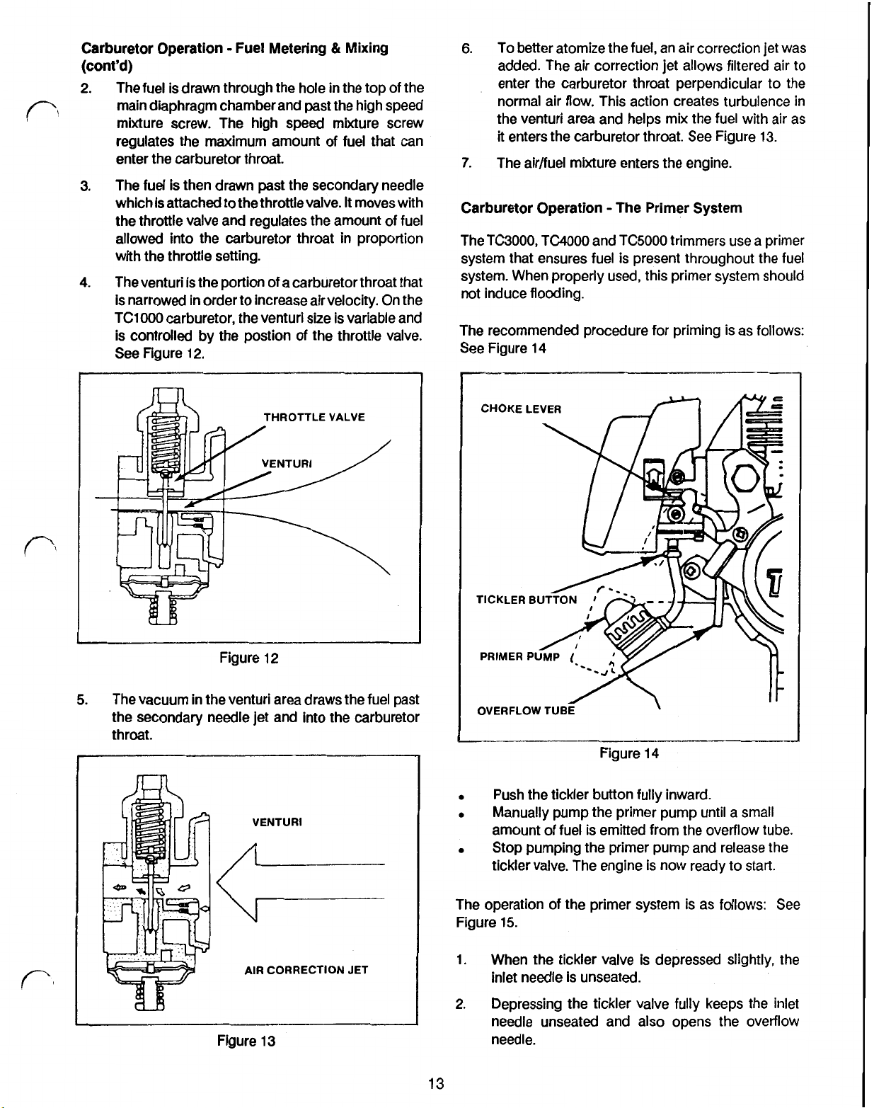
MAIN
DIAPHRAGM
CAVITY INLET
Figure
10
NEEDLE
Carburetor Operation Fuel Metering Mixing
With the main diaphragm filled with fuel, the carburetor
meters the amount going into the engine by using the
high speed mixture screw and the needle
entering the intake port
with air to further atomize
of
the engine, the fuel is mixed
it
and increase its
jet.
Before
combustibility.
The metering and mixing operation is described below:
See Figure
11.
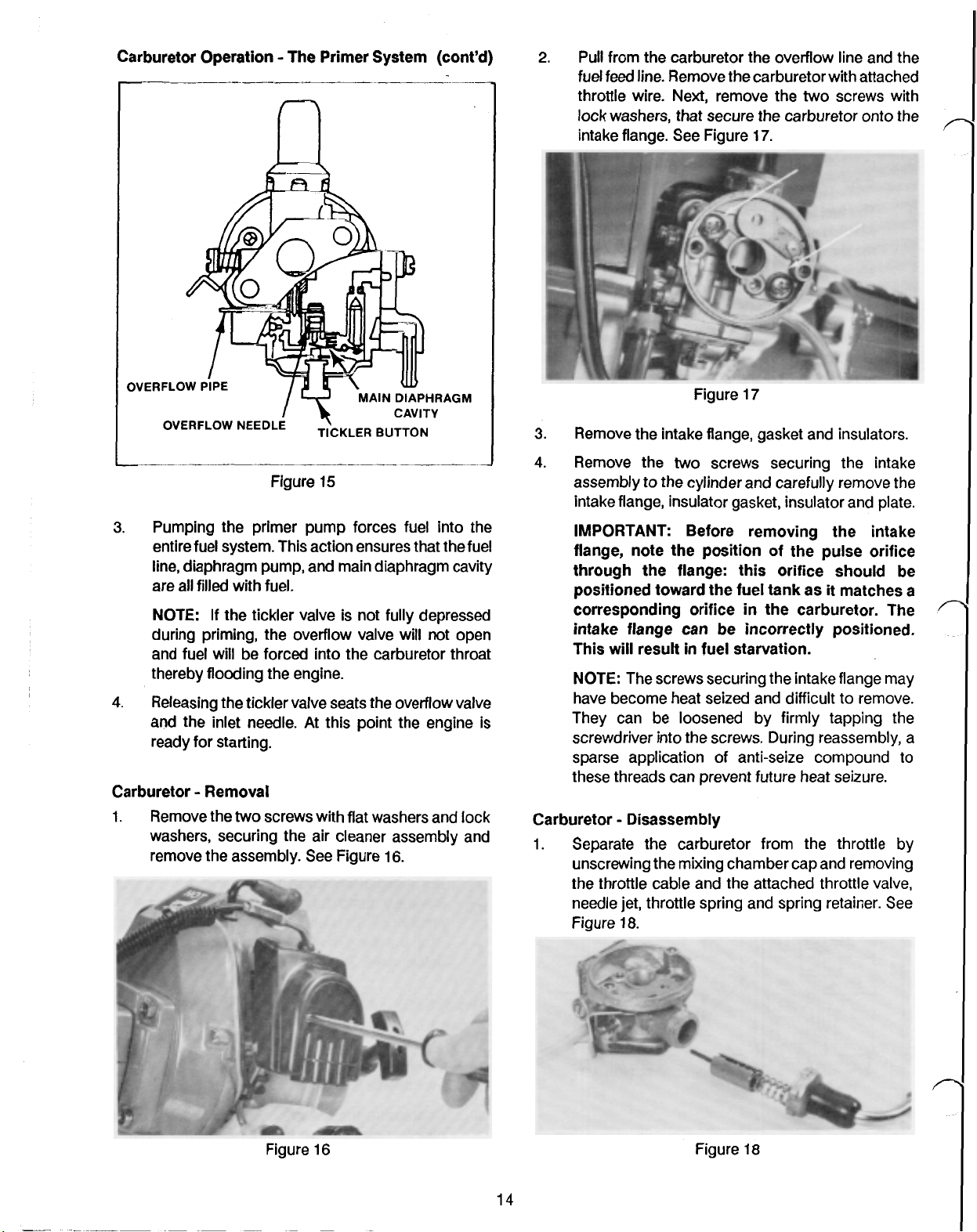
n
THROTTLE VALVE
SECONDARY
NEEDLE JET
NOTE:
The inlet needle is spring loaded in the
closed position. The spring pressure is very slight
and is easily overcome by the force of the fuel
coming through the passage.
5.
The fuel enters the main diaphragm cavity.
Figure
NOTE:
reservoir
10.
The main diaphragm serves only as a
so
that fuel can be properly metered
before entering the venturi. It does not do any
pumping of fuel during normal operation.
6.
Once the positive pressure is gone, the needle
valve is reseated. This allows fuel to
be
drawn from
the sealed main diaphragm cavity and into the
carburetor throat on the intake stroke.
See
12
HIGH SPEED
MIXTURE screw
CAVITY
Figure
1.
On the intake stroke, vacuum in the carburetor
11
throat draws fuel from the main diaphragm cavity.
Note that as the intake stroke begins, the main
diaphragm cavity is filled with fuel and that the
diaphragm is bowed toward the cover.
Page 24
Carburetor Operation Fuel Metering & Mixing
(cont’d)
2.
The fuel is drawn through the hole in the top of the
main diaphragm chamber and past the high speed
mixture screw. The high speed mixture screw
regulates the maximum amount of fuel
that
enter the carburetor throat.
3. The fuel is then drawn past the secondary needle
which is attached to the throttlevalve.
It
moves with
the throttle valve and regulates the amount of fuel
allowed into the carburetor throat in proportion
with the throttle setting.
4. The
venturi
is the portion of a carburetor throat that
is narrowed in order to increase air velocity. On the
TC1000 carburetor, the venturi size is variable and
is controlled by the postion
See Figure
12.
of
the throttle valve.
can
6.
To better atomize the fuel, an air correction
jet
was
added. The air correction jet allows filtered air to
enter the carburetor throat perpendicular to the
normal air flow. This action creates turbulence in
the
venturi area and helps mix the fuel with air as
it
enters the carburetor throat.
7.
The air/fuel mixture enters the engine.
See
Figure 13.
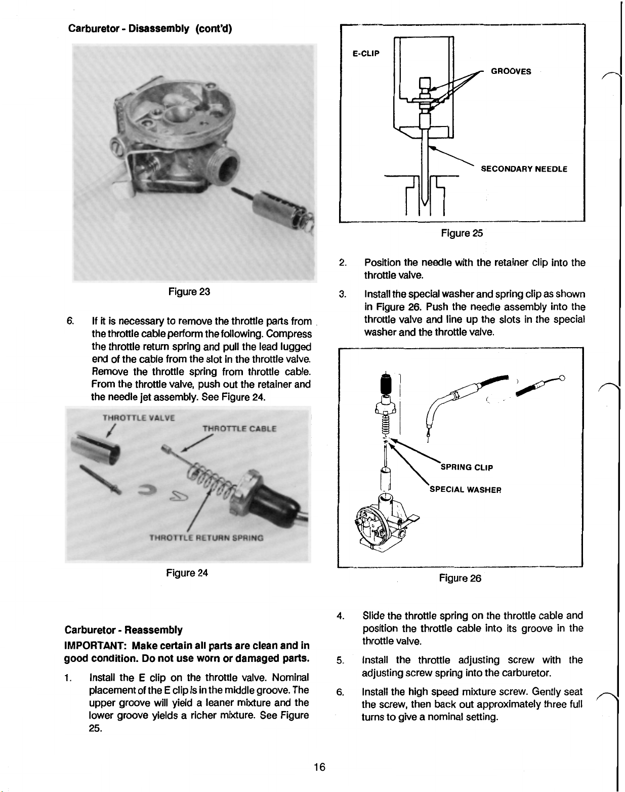
Carburetor Operation The Primer System
The TC3000, TC4000 and TC5000 trimmers use a primer
system that ensures fuel is present throughout the fuel
system. When properly used, this primer system should
not induce flooding.
The recommended procedure for priming is as follows:
See Figure
14
THROTTLE
VALVE
Figure 12
5.
The vacuum in the venturi area draws the fuel past
the secondary needle jet and into the carburetor
throat.
VENTURI
CHOKE
OVERFLOW
LEVER
TUBE
\
Figure 14
Push the tickler button fully inward.
Manually pump the primer pump until a small
amount of fuel is emitted from the overflow tube.
Stop pumping the primer pump and release the
tickler valve. The engine is now ready to start.
AIR
CORRECTION
Figure 13
JET
The operation
Figure 15.
1.
2.
13
of
the primer system is as follows:
When the tickler valve is depressed slightly, the
inlet needle is unseated.
Depressing the tickler valve fully keeps the inlet
needle unseated and also opens the overflow
needle.
See
Page 25
Carburetor Operation The Primer System (cont’d)
2.
Pull from the carburetor the overflow line and the
fuel feed line. Remove the carburetor with attached
throttle wire. Next, remove
the
two
screws with
lock washers, that secure the carburetor onto the
intake flange. See Figure
17.
MAIN
DIAPHRAGM
CAVITY
OVERFLOW
3.
Pumping the primer pump forces fuel into the
NEEDLE
Figure
TICKLER
15
BUTTON
entire fuel system. This action ensures that the fuel
line, diaphragm pump, and main diaphragm cavity
are all filled with fuel.
NOTE: If the tickler valve is not fully depressed
during priming, the overflow valve will not open
and fuel will be forced into the carburetor throat
thereby flooding the engine.
4.
Releasing the tickler valve seats the overflow valve
and the inlet needle. At this point the engine is
ready for starting.
Carburetor Removal
1.
Remove the
two
screws with flat washers and lock
washers, securing the air cleaner assembly and
remove the assembly. See Figure
16.
Figure
3.
Remove the intake flange, gasket and insulators.
4.
Remove the
assembly
two
to
the cylinder and carefully remove the
17
screws securing the intake
intake flange, insulator gasket, insulator and plate.
IMPORTANT: Before removing the intake
flange, note the position of the pulse orifice
through the flange: this orifice should be
positioned toward the fuel tank as
corresponding orifice
in
the carburetor. The
it
matches a
intake flange can be incorrectly positioned.
This will result
NOTE:
The screws securing the intake flange may
in
fuel starvation.
have become heat seized and difficult to remove.
They can be loosened by firmly tapping the
screwdriver into the screws. During reassembly, a
sparse application of anti-seize compound to
these threads can prevent future heat seizure.
Carburetor Disassembly
1.
Separate the carburetor from the throttle by
unscrewing the mixing chamber cap and removing
the throttle cable and the attached throttle valve,
needle jet, throttle spring and spring retainer. See
Figure
18.
Figure
16
14
Figure
18
Page 26

Carburetor Disassembly (cont'd)
2.
Remove the fuel pump by removing
the
with lock washers securing the pump cover then
lifting
off
the pump diaphragm and pump cover
gasket.
NOTE:
The gasket and the diaphragm are
extremely thin and may stick together giving
appearance of one piece. Remember that the
pump diaphragm seals against the pump cover
and that the gasket seals against the carburetor
body. See Figure 19.
4
screws
the
NOTE:
Before removing inlet needle pieces,
inspect inlet needle arm height using a depth
micrometer. The correct height is
(.055
to
.062”)
See Figure 21.
INLET NEEDLE
1.4
ARM
HEIGHT
INLET NEEDLE
Figure 21
to 1.6 mm
Figure 19
Remove the four screws with lock washers
3.
securing the main diaphragm cover assembly to
lift
off
the carburetor. Carefully
the main diaphragm
cover assembly.
NOTE:
The main diaphragm assembly and the
main diaphragm packing are thin and may stick
together giving the appearance of one piece, not
two.
Remember that the main diaphragm gasket
seals against the carburetor body. See Figure 20.
Remove the inlet needle pieces from the
carburetor by removing the inlet needle pin set
screw and carefully lifting out the inlet needle arm
with inlet needle pin, the inlet valve spring and the
inlet needle valve. See Figure 22.
INLET NEEDLE
ARM AND
PIN
Figure 20
15
Figure 22
5.
Remove the throttle adjusting screw, throttle
adjusting screw spring and the high speed mixture
screw. See Figure
23.
Page 27
Carburetor Disassembly (cont’d)
E-CLIP
GROOVES
SECONDARY NEEDLE
Figure
23
Figure
2.
Position the needle with the retainer clip into the
25
throttle valve.
3.
Install the special washer and spring clip as shown
in Figure
26.
Push the needle assembly into the
throttle valve and line up the slots in the special
washer and the throttle valve.
Carburetor Reassembly
IMPORTANT
good condition.
1.
Install the
placement
Make certain all parts are clean and
Do
not use worn or damaged parts.
E
clip on the throttle valve. Nominal
of
the E clip is in the middle groove. The
upper groove will yield a leaner mixture and the
lower groove yields a richer mixture.
25.
See
in
Figure
Figure
4.
Slide the throttle spring on the throttle cable and
26
position the throttle cable into its groove in the
throttle valve.
5.
Install the throttle adjusting screw with the
adjusting screw spring into the carburetor.
6.
Install the high speed mixture screw. Gently seat
the screw, then back out approximately three
turns to give a nominal setting.
full
Page 28

Carburetor Reassembly
7.
Replace the inlet needle pieces by installing the
inlet
needle, the
(cont’d)
inlet
needle spring, the inlet needle
arm and secure with the screw. See Figure
/--
SCREW
27.
OVERFLOW
VALVE
INLET
NEEDLE
ARM
INLET
NEEDLE
PIN
INLET
NEEDLE
9.
Replace the main diaphragm parts by installing the
main diaphragm gasket against the carburetor, the
main diaphragm assembly upon the main
diaphragm gasket, the main diaphragm cover
upon the main diaphragm assembly. When
installing the main diaphragm assembly, position
the shaft of the pin toward the inlet needle arm, not
toward the tickler button.
NOTE:
Sealant is not recommended on these
gasket surfaces.
Secure these pieces with four screws with lock
washers. See Figure
29.
CARBURETOR
Figure
27
BODY
Make certain the spring is securely seated in the
inlet needle arm and that the inlet arm positively
engages the inlet valve.
I
8.
Using the carburetor body surface as reference,
check the inlet valve height. Inlet valve height can
be checked with a height gauge or with an
accurate depth gauge. See Figure
28.
Carburetor Inlet Needle Valve Height
1.4
to
1.6
mm
(.055
to
.063”)
Figure
INLET
NEEDLE
ARM
HEIGHT
Replace the fuel diaphragm pump parts by
10.
29
installing the pump cover gasket against the
carburetor, the pumpdiaphragm against the pump
cover gasket, the pump cover against the pump
INLET
NEEDLE
diaphragm and securing these pieces with four
screws with lock washers. See Figure
30.
SPRING
17
NOTE:
Sealant is not recommended on these
gasket surfaces.
Install the throttle cable with attached throttle parts
11.
into the carburetor and secure by tightening the
throttle fitting.
The carburetor is completely reassembled and
ready for installation to the intake flange.
Page 29
Carburetor Reassembly (cont’d)
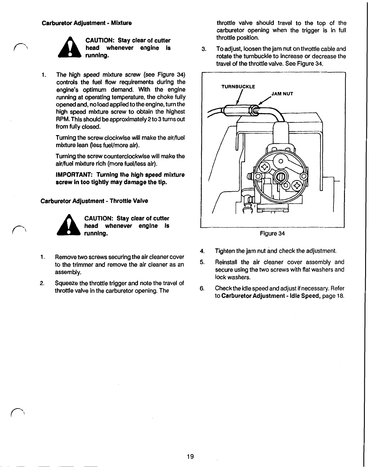
3.
Ensure that the throttle cable is positioned as
shown in Figure 32 to prevent throttle cable
damage.
Figure 30
Carburetor
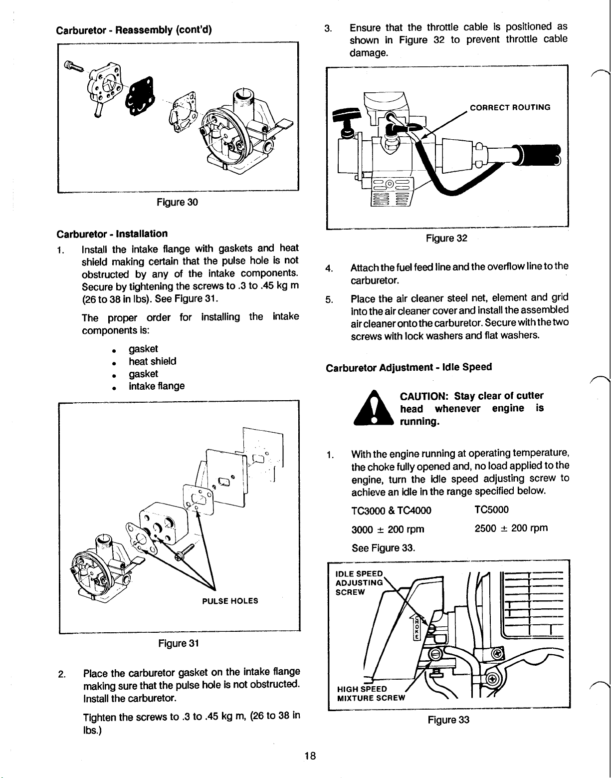
I.
Install the intake flange with gaskets and heat
Installation
shield making certain that the pulse hole is not
obstructed by any of the intake components.
Secure by tightening the screws to .3 to
(26 to 38 in Ibs). See Figure 31.
The proper order for installing the intake
components is:
gasket
heat shield
gasket
intake flange
.45
kg m
CORRECT
ROUTING
Figure 32
4.
Attach the fuel feed line and the overflow line to the
carburetor.
5.
Place the air cleaner steel net, element and grid
into the air cleaner cover and install the assembled
air cleaner onto the carburetor. Secure with the
screws with lock washers and flat washers.
Carburetor Adjustment Idle Speed
CAUTION:
head whenever engine
Stay
clear
of
cutter
is
running.
two
Figure 31
2. Place the carburetor gasket on the intake flange
making sure that the pulse hole is not obstructed.
Install the carburetor.
Tighten the screws to .3 to
.45
kg m, (26 to 38 in
Ibs.)
1. With the engine running at operating temperature,
the choke fully opened and,
no
load applied to the
engine, turn the idle speed adjusting screw to
achieve an idle in the range specified below.
TC3000
3000
&
TC4000
200 rpm
TC5000
2500
200
rpm
See Figure 33.
Figure 33
n
18
Page 30
Carburetor Adjustment Mixture
A
1.
The
controls the fuel flow requirements during the
engine's optimum demand. With the engine
running at operating temperature, the choke fully
opened and, no load applied to the engine, turn the
high speed mixture screw to obtain the highest
RPM.
from fully closed.
Turning the screw clockwise will make the air/fuel
mixture lean (less fuel/more air).
Turning the screw counterclockwise will make the
air/fuel mixture rich (more fuel/less air).
IMPORTANT: Turning the high speed mixture
screw
CAUTION:
head whenever engine is
running.
high
speed mixture screw (see Figure
This should be approximately2 to 3 turns
in
too tightly may damage the tip.
stay
clear
of
cutter
34)
out
throttle valve should travel to the top
carburetor opening when the trigger is in
throttle position.
3.
To adjust, loosen the jam nut on throttle cable and
rotate the turnbuckle to increase or decrease the
travel of the throttle valve. See Figure
--
TURNBUCKLE
JAM
NUT
34.
of
the
full
Carburetor Adjustment Throttle Valve
CAUTION: Stay clear
head whenever engine is
running.
1.
Remove
to the trimmer and remove the air cleaner as an
assembly.
2.
Squeeze the throttle trigger and note the travel
throttle valve in the carburetor opening. The
two
screws securing the air cleaner cover
of
cutter
Figure
4.
Tighten the jam nut and check the adjustment.
5.
Reinstall the air cleaner cover assembly and
secure using the
lock washers.
two
34
screws with flat washers and
of
6.
Check the idle speed and adjust
to
Carburetor Adjustment
if
necessary.
Idle
Speed, page
Refer
18.
19
Page 31

SECTION 2 FUEL SYSTEM
FUEL TANK
Fuel Tank Removal
I.
Loosen the
hex screws that retain the fuel tank guard. Remove
the fuel tank guard. See Figure 35.
two
locknuts and the corresponding
Figure
35
3. Remove the fuel tank.
if
4. The bracket can be removed,
removing the single machine screw retaining
the crankcase.
5.
The strap can be removed,
backing out the four Phillips fan housing screws
approximately 3/16' each. This will provide
sufficient clearance to remove the strap.
IMPORTANT:
fan housing screws unless absolutely
necessary as loosening them
ignition coil air gap.
necessary,
before running engine.
Fuel Tank Installation
1. With the fan housing loosely secured to the
crankcase, slip the fuel tank strap into its slot on
the underside of the engine. Tighten evenly the four
Phillips screws retaining the fan housing to the
crankcase to .4 to
Figure 37.
(TC5000
do
not forget to reset the air gap
only)
If
removal of the strap is
.5
kg m (35 to 43
necessary, by
if
necessary, by
Do
not loosen the
will
affect the
in
Ibs). See
it
to
2.
Loosen the locknut on the fuel tank strap screw
then turn the screw counterclockwise until the strip
is free from the bracket. See Figure 36.
Figure 36
Figure 37
NOTE:
loosened, the
See
2.
Fasten the strap bracket to the underside of the
crankcase using the single machine screw.
3. Start the fuel tank strap screw into the strap bracket
and turn clockwise until the tank is seated on all
four pads.
locknut.
(TC5000
TC5000
only) If the fan housing was
air
gap must be reset before starting.
Air Gap Adjustment, page
DO
NOT OVERTIGHTEN. Tighten the
28.
Page 32

Fuel Tank Installation (cont’d)
4. Slide the fuel tank guard into the lower fan housing
and tighten the
the
two
corresponding locknuts.
5.
Slide the retaining ring onto the fuel line, then push
two
hex screws retaining
it.
Tighten
the line onto the fitting near the primer bulb. Slide
the retainer ring down, over the fitting, to secure
the line. See Figure 38.
Push the tickler button fully inward.
Manually pump the primer pump until a small
amount of fuel is emitted from the overflow tube.
Stop pumping the primer pump and release the
tickler valve. The engine is now ready to start.
Primer Pump Operation
The primer system on the TC3000, TC4000 and
is
used
on cold starts only and ensures that fuel is
present throughout the entire fuel system.
TC5000
It
relies on
manual pumping action to draw fuel into the primer and
to pump
The primer pump uses a
it
into the fuel line and the carburetor.
two
step operation to pump fuel
to the carburetor. Pushing on the primer diaphragm does
the following: See Figure 40.
INLET CHECK BALL
OUTLET CHECK BALL
Figure 38
PRIMER PUMP
Primer Pump Proper Use
Proper operation of the primer system is as follows:
See
Figure 39.
CHOKE LEVER
VALVE CUSHION
Figure 40
1. The inlet check ball seats.
2.
The outlet valve is pushed against the porousvalve
cushion to allow fuel or air (whatever is in the
primer diaphragm) to pass into the fuel line and
carburetor.
Releasing the primer diaphragm allows
back
to
its
original shape which results in the
following: See Figure 41.
FUEL FLOW
\
\
VALVE CUSHION CHECK BALL
VALVE CUSHION
it
to come
OUTLET
OVERFLOW
TUBE
\
Figure 39
21
INLET CHECK BALL
~--~-
Figure 41
1.
The vacuum produced
by
the diaphragm seals the
outlet check valve. This prevents fuel from being
drawn from the fuel line.
Page 33

Primer Pump Operation (cont'd)
2.
The inlet valve
is
drawn toward the porous valve
cushion which allows fuel to be drawn from the
pickup line inside the tank. This action fills the
primer diaphragm with fuel and readies
next pump.
Primer Pump Disassembly
1.
Pull
the primer pump from the tank and remove the
fuel line. The primer pump is press fit into the fuel
tank. See Figure
42.
it
for the
Figure 42
2.
Unscrew the rubber cap/button from the pump.
See Figure
43.
Figure
44
Primer Pump Inspection
1.
Inspect the disassembled primer pump for
contamination or damaged parts.
2. Clean thoroughly in a mild soap and water solution.
3.
If
the primer pump is suspect after inspection, the
entire primer pump assembly should be replaced.
Primer Pump Reassembly
1.
Before reassembling, familiarize yourself with the
configuration of the parts
properly installed.
GASKET
E
See
\
Figure
to
ensure they are
45.
VALVE SEATE
n
3.
Carefully
cushion, and
lift
Figure
out
the top valve seat with the valve
two
43
ball
valves. See Figure
4. Insert a thin, non-puncturing punch through the
hole in the bottom of the pump and carefully push
out
gasket
A,
valve seat A with valve cushion, and
gasket B.
44
22
PUMP
BODY
Figure
Gasket
“B”
has
two
sizes of fuel orifices one
large and one small.
Gasket
"A"
has one size of fuel orifices both
large.
45
Page 34

Primer Pump Reassembly (cont'd)
Valve seat
through the seat.
Valve seat
partially cut into the seat.
Gasket
pump. Gasket
outside.
Reassemble parts into the pump body. Position
2.
gasket
nozzle of the pump body.
Place valve seat
3.
"A"
has a locating notch that is cut
"B"
has
"A"
and valve seat
"B”
B
so
the
small fuel orifice is toward the outlet
a locating notch that is
"A"
are inside the
and valve seat
A
with valve seats up, on gasket
"B”
B.
Push one valve cushion into valve seat
4.
covers the double holed fuel orifice.
Place gasket
5.
A
on valve seat
A.
are to the
A
so
these elements and the fuel strainer located inside
the pickup weight. Clean or replace as necessary.
Reassemble the pickup assembly making sure that
3.
the
pickup tube fits snugly on the top of the fiber
filter element.
If pickup tube removal is desired,
4.
removed by removing the primer pump as
described under Primer Pump Disassembly,
page
22.
Remove the fuel pickup tube by pulling
5.
tank. It is also pressed in.
Inspect the pickup tube for cracks or punctures
6.
and replace
it
Reinstall the fuel pickup tube by lightly coating the
7.
barbed end with
the proper tank orifice.
if
necessary.
two
cycle oil and pressing
it
can be
it
out of the
it
into
Drop the
6.
in valve seat
7.
Place one valve cushion into valve seat
covers the double-holed fuel orifice.
Set valve seat
8.
body with assembled parts.
Secure all parts by screwing the rubber cap/button
9.
on the pump body.
Reinstall the pump into the tank opening and
10.
attach the fuel line.
Fuel Pickup Tube and Filter Service
1.
The fuel filter on the pickup tube can be inspected
without removing the pickup assembly by "fishing"
the filter out through the filter hole.
two
ball valves through gasket A to seat
A.
B
B
with valve cushion into the pump
See
so
Figure 46.
that
FUEL CAP
it
Fuel Cap Operation
The fuel tank cap on the TC3000, TC4000 and TC5000
somewhat complex due to the requirements of the
application. The cap must vent in order to prevent a
vacuum or pressure buildup within the tank but must also
prevent leakage of fuel.
The cap accomplishes the above by using a system of
valves which work under different conditions. When the
tank is under pressure, the following occurs:
47.
UMBRELLA VALVE
PACKING
'I
ORIFICE
See
is
Figure
2.
Pull the pickup weight from the end of the tube and
remove
the
fiber filter elements. Inspect both of
23
Figure 47
1.
The pressure passes through the packing orifice
so
that
it
can act upon the umbrella valve.
2.
The pressure passes through the
in
the valve holder and lifts the umbrella portion of
the umbrella valve
3.
Pressure passes into the top of the gas cap and
isemitted to the atmosphere through the slits in the
threads of the gas cap.
off
its seat.
two
small orifices
Page 35
Fuel Cap Operation (cont’d)
When a vacuum occurs within the tank, the following
occurs: See Figure
48.
Fuel Cap Inspection
1.
It
is important that the fuel cap properly vents the
tank. Inspect the gasket to ensure that the hole at
the rounded end is unobstructed.
2.
Check the
two
small pressure outlet holes in the
holder to ensure that they are open.
3.
The stem of the umbrella valve allows air into the
tank to compensate for the fuel being used by the
engine. Ensure that
it
will open and close by
holding the flat end lengthwise between your
thumbs and squeezing. See Figure
50.
UMBRELLA
Figure
1.
Atmospheric pressure enters the top of the gas cap
through the slits
2.
Because a vacuum in the tank means that higher
in
48
the gas cap threads.
VALVE
pressure is present outside the tank than within,
the higher pressure passes down the stem of the
umbrella valve and forces
3.
The higher pressure passes through the packing
the
stem orifice open.
orifice and enters the fuel tank thereby equalizing
the pressure.
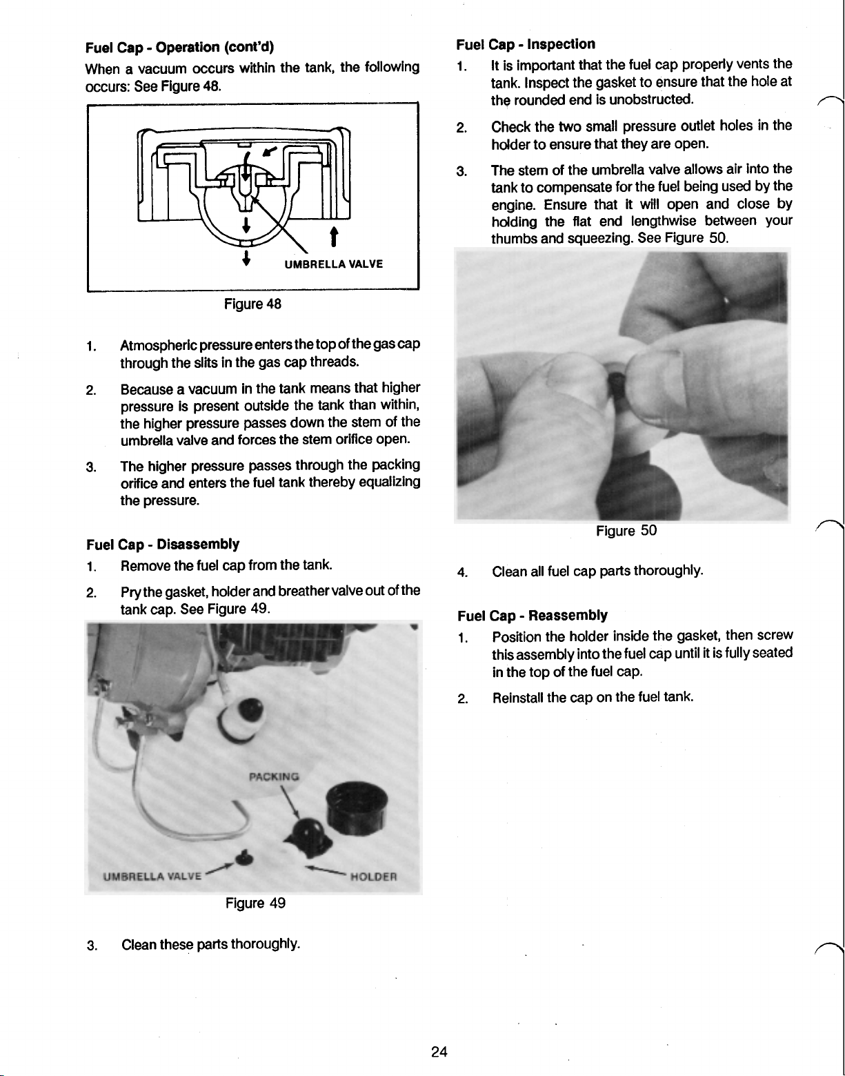
Fuel Cap Disassembly
1.
Remove the fuel cap from the tank.
2.
Pry the gasket, holder and breather valve out of the
tank cap. See Figure 49.
4.
Clean all fuel cap parts thoroughly.
Fuel Cap Reassembly
1.
Position the holder inside the gasket, then screw
this assembly into the fuel cap until
in the top of the fuel cap.
it
is fully seated
3.
Clean these parts thoroughly.
Figure 49
2.
Reinstall the cap on the fuel tank.
Page 36

SECTION
IGNITION
3
Ignition Operation
The firing of the spark plug at the proper time is the
culmination of a number of components working
together. In the TC3000,
components used are:
Flywheel
Ignition Coil
Trigger Module
Spark plug
See Figure
51.
TC4000,
SPARK PLUG,
and TC5000 the
flywheel magnets to cut through the coils to generate
electricity. See Figure
52
IGNITION
COIL
Low voltage is produced in the primary coil which
to
low to produce a spark at the spark plug.
The secondary coil serves
produced in the primary. To accomplish this, the
secondary coil must have many more windings than the
primary. The higher the ratio between the primary coil
a
Figure
The following describes the function of each of the above
components.
Ignition Operation Flywheel
The flywheel is connected directly to the crankshaft and
turns at the same speed as the engine. Imbedded in the
flywheel are three magnets. These magnets rotate past
the coil to generate electricity.
Imbedded in the opposite side of the flywheel is a steel
counterweight which offsets the weight of the three
magnets.
It
is not magnetic.
TRIGGER
51
MODULE
windings to secondary coil windings, the greater the
voltage amplification will be.
However, even though the secondary coil in the TClOOO
has considerably many more windings than the primary,
the voltage produced is still not high enough to produce
spark across the spark plug electrodes. To further
amplify the voltage, the trigger module is used
Ignition Operation Trigger Module
The trigger module amplifies the voltage in the
secondary coil by breaking the primary circuit just as the
primary voltage reaches its peak. This breaking of the
primary circuit results
field surrounding the primary coil. The collapse of the
primary magnetic field induces a large voltage surge in
the secondary which is sufficient to produce a spark
across the spark plug electrodes.
is
sent
the trigger module. The primary voltage is much too
to
amplify the voltage
in
a rapid collapse of the magnetic
Ignition Operation Ignition Coil
It
The ignition coil is actually a transformer.
close to the flywheel to allow the magnetic field of the
is positioned
Before getting into the actual electronics used inside the
trigger module,
of the voltage waveform produced by the flywheel
magnets moving by the ignition coil.
it
is important to have an understanding
See
Figure
53.
25
Page 37

lgnition Operation Trigger Module (cont'd)
The following is the process the trigger module uses to
break the primary circuit to produce spark:
55
See
Figure
PRIMARY VOLTAGE WAVEFORM
Figure
53
As
the magnets rotate past the coil, voltage is produced.
This voltage, when uninterrupted, is first positive, then
negative as the magnet passes by the coil. This effect is
caused by the
Explanation of the trigger module also requires an
understanding of the
I
two
opposing poles of the magnet.
NPN
transistor. See Figure
C
(Collector)
54.
I
E
(Emitter)
Figure
1.
The magnet passes by the coil and induces an
alternating voltage.
2.
As
the voltage begins to increase, (approximately
point "a"
and current flows from point
through
3.
Current
current
that
in
Figure
R3,
R4,
and Tr2. See Figure
Figure
l1
flowing through Tr2 induces a larger
12.
Note that current
l2
is much larger. See Figure
53)
transistor
55
56
l1
Tr2
"C'
is
very
57.
is
turned on
to
point
56.
small and
"D"
NPN-type
Figure
A
transistor
requires across the base and emitter (points B and E in
Figure
turned on,
above. At
current,
current
l1.
Thus, the transistor functions
allows a small current to control a large one.
has
a certain minimum voltage that
54
above) before
it
allows a small current,
the
same time, the transistor allows a large
12,
to
flow from point C to
l2
will vary in proportion to the smaller current,
54
it
will "turn on". Once
l1,
to flow as shown
E.
The magnitude of
as
an amplifier in that
it
has
MTI
unit Ignition
it
it
4.
When the voltage
in "Figure
is
at the point
53,
Tr1 is still in the
coil
Spark
"a"
level as denoted
off
mode
Ground
plug
26
Page 38

Ignition
5.
Operation Trigger Module (cont'd)
and allows no current
l3
or l4
to
flow.
As the voltage produced in the primary coil
reaches
its
negative peak (point
"b
in
Figure 53),
transistor Tr1 is turned on and allows small current
l3
and large current l4 to
MTI
unit Ignition
flow.
See Figure 58.
coil
TERMINAL NUT
METAL SHELL
Ground
Spark
plug
Figure
6.
When transistor Tr1 turns on, nearly all of the
58
current flow through R4 and Tr2 is diverted through
path l4 since
in
drop
Off.
7.
When Tr2 turns off, current
it
is the path of least resistance. This
current I1 results
in
transistor Tr2 turning
l2
drops rapidly and
causes the magnetic field surrounding the primary
in
coil to rapidly collapse. This
voltage surge
to
produce a spark across the spark plug.
in
the secondary which is sufficient
Another task the trigger module performs is
turn causes a
to
limit the
maximum revolutions per minute that the engine will
attain.
It
does this by means of the ITDC (ignition timing
delay circuit) which can also be seen
in
Figure 55.
This circuit senses the engine speed, and, as it
approaches 10,000 rpm,
it
delays the turning on of
transistor Tr1 slightly. This retards the timing and
prevents the engine from further acceleration.
CENTER LEG INSULATOR
ELECTRODE
GROUND ELECTRODE GAP
Figure
59
The other important area is the insulator. The insulator
prevents arcing from taking place in another portion of
the plug, away from the electrodes. Because of the
extremely high voltage present, even a slight crack or
fouling of the head insulator can result in arcing and a
malfunction of the plug.
AIR GAP ADJUSTMENT
The space between the coil and the flywheel magnets is
called the "air gap". Because the coil mounting holes are
oversized, air gap on the TC3000, TC4000, and TC5000
is adjustable.
It
is important
to
set
it
to the proper
specification to ensure strong spark and proper timing.
TC3000/TC4000 Air Gap Adjustment Preparation
1.
For convenience, remove the engine from
the
drive
tube as described under Engine Removal from
Drive Tube, page 40.
2.
With the recoil assembly on a hard flat surface, use
an impact wrench to remove the four fan housing
screws. Remove the fan housing.
Ignition Operation Spark Plug
The spark plug is used to ignite the air/fuel mixture by
producing a spark just before the piston reaches top
dead center.
shown
There are two critical areas important
in
Figure
A
spark plug
56.
is
typically constructed as
to
proper spark
TC3000/TC4000 Air Gap Adjustment
NOTE: If coil performance is suspect, check the air gap
with a feeler gauge prior
mounting screws.
0.020').
1. Loosen the
plug function. The first is that the electrodes are properly
gapped and are clean. This ensures that a strong spark
will be present and that
it
occurs at the proper time.
Excessive gap or fouling can delay firing enough to
cause a
loss
of power or stalling.
27
to
loosening
It
should be 0.4
two
coil mounting screws. Position a
to
the
0.5 mm
two
(0.016
coil
to
feeler gauge between the coil and the flywheel near
one of the coil mounting screws and tighten.
Repeat this procedure for the other end of the coil.
Air gap adjustment is now complete. See Figure
60.
Page 39
TC3000/TC4000 Air Gap Adjustment (cont'd)
Figure
60
Figure 61
TC300O/TC4000 Air Gap Adjustment Reassembly
1. Install the fan housing. Tighten the screws to
0.5
kg m
(35
to
43
in Ibs).
2.
Install the plastic fan housing cover using three
i
Phillips screws.
3.
Mount the engine on the drive tube as described
in Engine Installation on Drive Tube, page
0.4
to
45.
TC5000 Air Gap Adjustment Preparation
1. Remove the carburetor
Carburetor Removal, page
2.
Remove the three screws securing the muffler
cover and remove the cover.
as
described under
14.
Also
Figure 62
remove the
muffler at this time. TC5000 Air Gap Adjustment Reassembly
3.
Remove the screw securing the cylinder Cover to
the cylinder. Remove the cover.
1. Install the cylinder cover. Make sure that the coil
wire and grommet are properly positioned in the
cylinder cover slot.
2. Install the muffler and muffler cover.
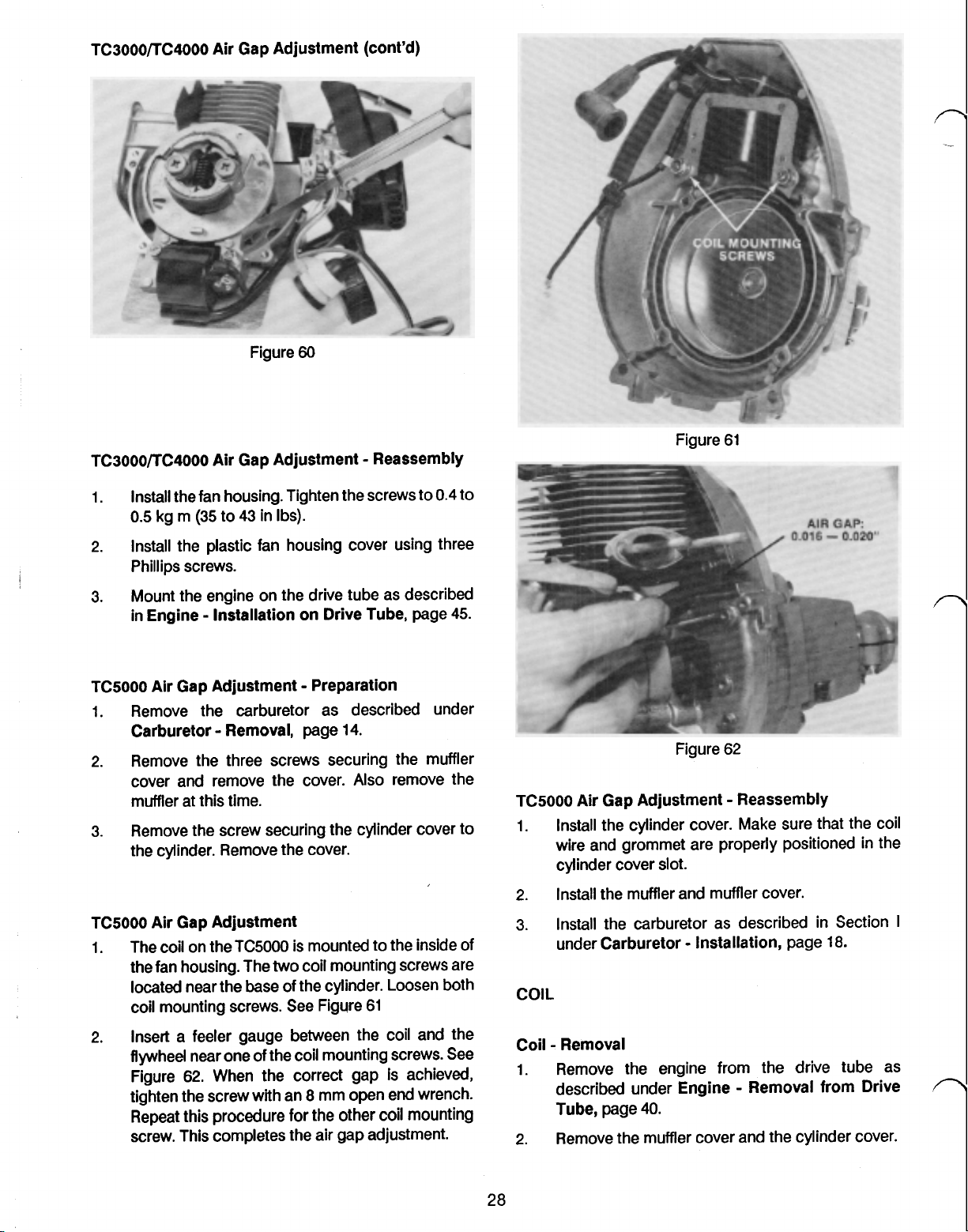
TC5000 Air Gap Adjustment
1. The coil on the TC5000 is mounted to the inside
of
3.
Install the carburetor as described in Section
under Carburetor Installation, page 18.
the fan housing. The two coil mounting screws are
located near the base of the cylinder. Loosen both
coil mounting screws. See Figure 61
2.
Insert a feeler gauge between the coil and the
flywheel near one of the coil mounting screws. See
Figure 62. When the correct gap is achieved,
tighten the screw with an
8
mm open end wrench. described under Engine Removal from Drive
Repeat this procedure for the other coil mounting
Coil Removal
1.
Remove the engine from the drive tube as
Tube,
screw. This completes the air gap adjustment. 2. Remove the muffler cover and the cylinder cover.
28
page
I
40.
Page 40

Coil Removal (cont'd) Coil Installation
3.
Remove the fuel tank as described under Fuel
20,
Tank Removal, page
to gain access to screws. Be sure to install the rubber insulating
ignition wiring.
4.
Pull
out
the
two
male connectors leading into the
female connector found beneath the carburetor.
5.
Position the engine assembly
so
that the recoil
1.
Install the trigger module using
gasket beneath
2.
Install the coil with the proper air gap by following
the procedure found under heading:
ADJUSTMENT,
housing is resting on a hard, flat surface. Remove
the four Phillips head screws retaining the fan
housing with an impact wrench and
housing. (The
fan housing
TC5000
so
be careful not to damage any wires
has the coil mounted in the
lift
off
the fan
while removing the housing.)
6.
Remove the trigger module and gasket. See Figure
63.
it.
See Figure
page
27.
63.
two
machine
AIR
GAP
Figure
63
29
Page 41

SECTION
4
RECOIL STARTER
Recoil Starter Operation
An
exploded view of the recoil assembly used on the
TC3000, TC4000 and the TC5000 is shown below. See
Figure
64.
STARTER RETURN REEL
PULLEY CLOCKSPRING
FRICTION
The recoil mechanism shown in Figure
follows:
The operator pulls the rope which
it
reel spinning. As the reel turns,
in
the recoil housing. The clock spring rewinds the rope
once the
“T”
handle is released.
winds up a clock spring
64
in
turn results
functions as
in
the
starter pulley and
When the reel stops turning, the starter pawl is forced
back into
spring.
Recoil Mechanism Removal
1.
Recoil Mechanism Disassembly
1.
its
Remove the three (TC3000 and TC4000) or four
(TC5000) screws retaining the recoil housing to the
crankcase and remove the recoil starter unit.
N0TE: There
starter housing.
during removal from the crankcase.
Pull
out a loop of starter rope approximately
(12
inches) and tie a tight slip knot to keep
rewinding. This loop will provide
necessary to untie the knot from the
See Figure
in
turn, forces the engine to turn over.
normal retracted position by the return
is
no spring tension against
It
should not fly
off
nor unwind
the
“T”
the
recoil
30
it
slack
handle.
from
66.
cm
Note that the pawl pivots
kept in its normally retracted position by the return
spring. See Figure
As
the reel begins to turn, the pawl turns with
it
is
in contact with the friction plate which does not
rotate. This contact between the pawl and the friction
plate forces the pawl outward
65.
in
the recoil reel and that
Figure
65
so
that
it.
However,
it
engages the
it
is
Figure
Once the
rope to slowly retract into the recoil housing.
2.
Remove the bind screw.
protection and leather gloves are
recommended
recoil housing.
3. Gently
friction spring, and pawl.
“T”
handle has been removed, allow the
CAUTION: Once the
screw is removed,
for the recoil spring to fly out of
the recoil housing. Eye
during
lift
off
as an assembly the friction plate,
66
bind
it
is possible
servicing of the
30
Page 42

Recoil Mechanism Disassembly (cont'd)
CAUTION:
plate and reel components
carefully as jerking them out
may cause the recoil spring to
come out of the recoil housing.
4.
Remove the return spring.
remove the friction
See
Figure 67.
CAUTION:
wire surrounding the spring
A
the
personal injury.
until the spring is installed in
the recoil housing. Removing
wire prematurely may result
Do
not remove
the
in
Figure 67
5.
Gently
pliers.
A
6. Untie the knot in the recoil rope and remove the
rope from the recoil reel.
7.
If
by carefully turning the recoil housing over (spring
side down) and rapping
sure to stay clear of the spring when performing
this operation.
IMPORTANT
unless
unsprung, the spring should be replaced.
lift
out the recoil reel with a needle nose
CAUTION:
from the recoil starter case, the
spring may fly
it
is necessary to remove the recoil spring, do
Do not remove
it
is
If the reel is jerked
out
of
position.
it
on a hard flat surface. Be
the
recoil spring
absolutely necessary. Once
so
Figure 68
2.
Insert one end of the recoil rope into the
appropriate hole in the recoil reel.
knot in that end of the rope and
the hole making sure that no portion
protrudes
out
of
the recess.
See
Figure 69.
Tie
pull
a single
it
down into
of
the rope
loop
Recoil Mechanism Reassembly
1.
If
the recoil spring was removed during
it
disassembly, replace
the spring with the wire on
as
shown in Figure
with a
it
68.
new
one. Position
into the recoil housing
31
Figure 69
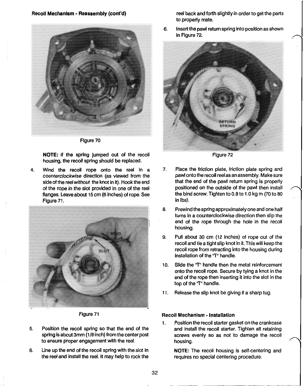
3.
Position the spring in the starter case
spring's inner end is approximately
from the shaft. This distance ensures that the reel
hook will engage the spring.
See
3
mm
Figure
so
(1/8
70.
that the
inch)
Page 43
Recoil Mechanism Reassembly (cont'd)
reel back and forth slightly in order
to
properly mate.
6.
Insert the
in Figure
pawl
return spring into position as shown
72.
to
get the parts
NOTE:
If
the spring jumped
out
of the recoil
housing, the recoil spring should be replaced.
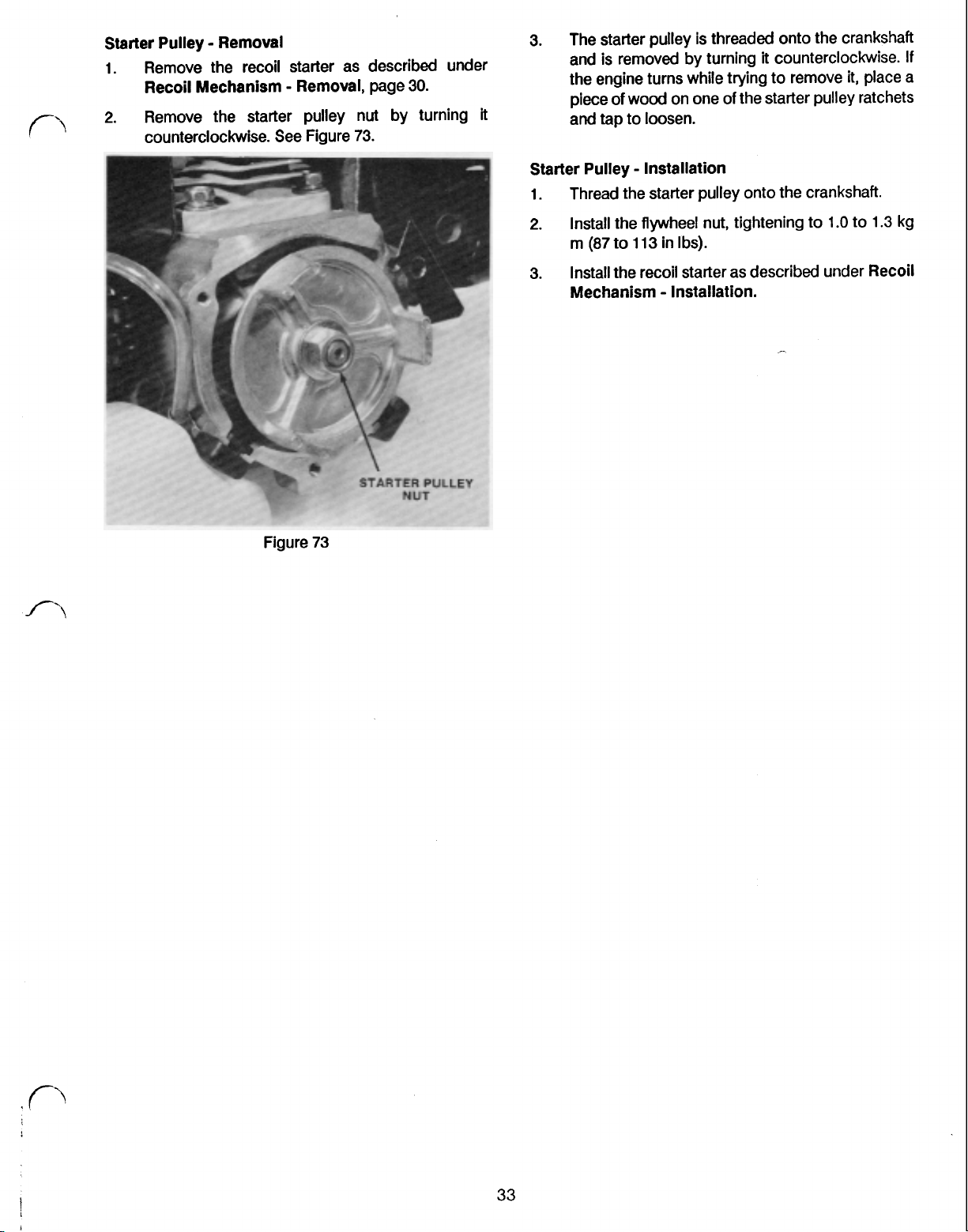
4.
Wind
counterclockwise
side of the reel
the recoil rope onto the reel in a
direction (as viewed from the
without
the knot
in
it).
Hook the end
of the rope in the slot provided in one of the reel
flanges. Leave about
Figure
71.
15
cm
(6
inches) of rope.
See
Figure 72
7.
Place the friction plate, friction plate spring and
pawl onto the recoil reel as an assembly. Make sure
that the end of the
pawl
return spring is properly
positioned on the outside of the pawl then install
the bind screw. Tighten
to
0.8
to
1.O
kg m (70
to
in Ibs).
Prewind the spring approximately one and one half
8.
turns in a counterclockwise direction then slip the
end of the rope through the hole in the recoil
housing.
Pull about 30 cm (12 inches) of rope
9.
recoil and
tie
a tight slip knot in
it.
out
of the
This will keep the
recoil rope from retracting into the housing during
'7"
installation of the
Slide the
10.
“T”
handle then the metal reinforcement
handle.
onto the recoil rope. Secure by tying a knot in the
end of the rope then inserting
top of the
Release the slip knot be giving
11.
“T”
handle.
it
into the
if
a sharp
slot
tug.
in the
80
Figure
5.
Position the recoil spring
spring is about
to
ensure proper engagement
6.
Line up the end of the recoil spring with the
3mm
the reel and install the reel.
71
so
(1/8
inch) from the center post
It
may help to rock the
that
with
the end of the
the reel.
slot
in
Recoil Mechanism Installation
1.
Position the recoil starter gasket on the crankcase
and install the recoil starter. Tighten all retaining
so
screws evenly
as not to damage the recoil
housing.
NOTE:
The recoil housing is self-centering and
requires no special centering procedure.
Page 44
Starter Pulley Removal
1.
Remove the recoil starter as described under
Recoil Mechanism Removal, page
2.
Remove the starter pulley nut by turning
counterclockwise. See Figure
73.
30.
it
3.
The starter pulley is threaded onto the crankshaft
and is removed by turning
it
counterclockwise.
the engine turns while trying to remove
piece
of
and
tap to loosen.
wood on one
of
the starter pulley ratchets
Starter Pulley Installation
1.
Thread the starter pulley onto the crankshaft.
2.
Install the flywheel nut, tightening to
(87
to
113
m
3.
Install the recoil starter as described under Recoil
in Ibs).
Mechanism Installation.
1.O
it,
place a
to
1.3
If
kg
I
i
33
Page 45

SECTION 5 CLUTCH SHOES AND FLYWHEEL
Clutch Shoes and Flywheel Operation
74.
200
TC4000
parts
rpm
The TC3000,
clutch. The clutch
spring. These
in Figure
Operation of the clutch is as follows:
1.
When the trimmer engine speed is less than
spring holds the
clutch drum.
and TC5000 use a centrifugal type
is
constructed of two shoes and a
are fastened to the flywheel as shown
Figure
74
(3300
200
rpm on the TC5000) the
two
clutch shoes in, away from the
3900
3.
Remove the fan housing.
IMPORTANT: (TCSOOO only). The coil
mounted to the inside of the fan housing on
TC5000.
lead,
only, and swing
in
a
Clutch Shoes and Flywheel Inspection
1.
Inspect the clutch pads for even wear.
the clutch shoes for evidence of cracking.
2.
Inspect the clutch drum (found in the fan housing)
for roundness and even wear.
3.
Check the flywheel magnets using the screwdriver
method:. Hold the handle end of a flat bladed
screwdriver between your thumb and forefinger.
Bring the tip of the screwdriver to within
of the magnet to be tested. The screwdriver should
be drawn to the flywheel.
be replaced. Repeat this step for each magnet on
the flywheel. See Figure
To
avoid damaging
pull
up on the muffler side of the housing
the
fan housing out of the way
manner similar to that of opening a book.
the
coil ground
Also
3/4"
If
not, the flywheel should
75.
is
the
inspect
to
1"
2.
As
the engine speed reaches
(3300
force of the weights overcomes the spring and the
shoes make contact with the clutch drum. This
contact forces the drum to rotate with the engine
so
3.
Under deceleration, disengagement takes place at
a speed approximately
engagement speed. The difference between
engagement and disengagement speeds occurs
because the shoes resist disengagement slightly
when they are in contact with the clutch drum.
NOTE: Operating the trimmer for long periods of
time near the engagement speed may cause the
clutch to slip and overheat. This can result in
peeling of the clutch shoes.
Clutch Shoes and Flywheel Disassembly
1.
Remove the engine from the drive tube as
described under Engine Removal from Drive
Tube, page
200
rpm on the TC5000) the centrifugal
that power is transmitted to the trimmer head.
40.
3900
400
rpm less than the
200
rpm
2.
With the recoil assembly on a hard flat surface, use
an impact wrench to remove the
screws.
four
housing
34
Figure
75
Page 46

Clutch Shoes and Flywheel Inspection (cont'd)
4.
Check the flywheel for cracks or broken fins.
Clutch Shoes and Flywheel Removal
1.
Make note of
the
markings on the top of the clutch
shoes to ensure proper installation later.
2.
For convenience, remove the two fasteners
securing the coil
to
the block and move the coil to
the side.
3.
Using a strap wrench to hold the flywheel, remove
the two bolts retaining the clutch shoes. The shoes,
complete with the spring, can then be removed as
an assembly.
earlier are facing up. Then slide a flat washer over
so
the threads of each bolt
between the flywheel and the clutch shoes.
Figure
77.
that the washer rests
See
IMPORTANT: The flywheel
is
of
cast aluminum
design. Methods of holding the flywheel other
than with a strap-wrench may damage the
flywheel.
4.
Remove the flywheel nut by turning
counterclockwise using a strap-wrench to hold the
flywheel.
5.
Remove the flywheel using Tor0 flywheel puller
part number
41-7650.
Figure
See
76
Figure
76.
it
3.
Use
a small amount of Blue "Loctite" on the clutch
Figure
77
bolt threads and install the clutch shoe assembly.
Tighten the clutch bolts to
in
Ibs).
4.
Refer to
Coil
Installation, page
0.6
to
0.8
kg
m
29,
(52
for the
to
69
remainder of the reassembly procedure.
CLUTCH DRUM and CLUTCH HOUSING
Clutch Drum and Clutch
1.
Remove the snap ring from the drive shaft end of
Housing
Disassembly
the clutch drum.
2.
Press the clutch drum out of the clutch case by
pressing on the drive shaft only.
NOTE:
IMPORTANT: Use of a knockoff tool may dimple
the races in the crankshaft ball bearing. This
could lead to early failure of the bearing.
6.
Replace any damaged or worn
parts.
Clutch Shoes and Flywheel Reassembly
1.
If
the flywheel was removed, install the flywheel
key, then place the flywheel, fan side down, onto
the crankshaft. Hold the flywheel using a strap
wrench and tighten the flywheel nut to
(87
to
113
m
2.
!
Insert the clutch bolts through the clutch shoes
in Ibs).
1.O
to
1.3
kg
making sure that the markings you made note of
i
pressing or driving on the drive shaft. This will
dimple the ball bearings and could lead
premature failure. Whenever the clutch drum
removed, the clutch housing
be
3.
Remove the large snap ring retaining the bearings.
4.
Press
remove the washer.
5.
Inspect all parts and replace as necessary.
Clutch Drum and Clutch Housing Reassembly
The
TC3000
assembled as shown in Figure
Removing the clutch drum requires
replaced.
out
the bearing on an arbor press and
clutch drum and clutch housing are
78.
ball
bearing should
to
a
is
35
Page 47

Clutch Drum and Clutch Housing Reassembly
(cont’d)
The
TC4000
housing
CLUTCH
Figure
and
TC5000
is
assembled as shown
clutch drum and clutch
78
in
Figure
FAN
HOUSING
79.
Figure
5.
Install the small snap ring in the drive shaft end of
80
the housing.
6.
Check to ensure that the clutch drum rotates freely
and is true.
ISOLATION MOUNT (TC4000 and TC5000 only)
Figure
79
1.
Insert the washer into the clutch housing.
Press a new bearing into the clutch housing.
2.
IMPORTANT Press only on the outer race of
the bearing. Pressing on the inner race
damage the race inside the bearing and may
lead to premature failure.
3.
Install the large snap ring.
will
Isolation
Mount Operation
The TC4000 and TC5000 trimmers use a vibration
isolation system called an Isolation Mount.
81.
See
Figure
__---
HOLDER
Clutch
USING
CUSHIONS
HOLDER
n
4.
Support the inner race
of
the clutch housing
bearing from the drive shaft end with a sleeve or
deep well socket and press the clutch drum into
the housing. See Figure
80.
36
Page 48

Isolation Mount Operation (cont'd)
The system is constructed of
cushion holder. The cushions are positioned between
the holder and the clutch housing and are actually the
only
two
points of contact between the engine and the
drive tube. This arrangement allows vibration to pass
only through the
amount
Under normal circumstances, the Isolation Mount should
not require any maintenance for the life of the product.
However,
should be inspected and,
compressed, should be replaced.
Isolation Mount Disassembly
1.
of
if
Remove the single locating screw and the
clamping screws that secure the engine to the
drive tube and separate the engine from the drive
tube. See Figure
two
rubber cushions and reduces the
vibration that is transmitted
an increase invibration is noted, the cushions
two
rubber cushions and a
to
if
found to be damaged or
82.
the operator.
two
3.
Inspect the rubber cushions for wear and damage.
if
Replace
Isolation Mount Reassembly
1.
Position the rubber cushions on the clutch housing
as shown in Figure
necessary.
83.
Figure
82
NOTE:
linkage.
2.
Remove the two allen screws that secure the two
halves of the cushion holder and separate
halves.
It
is not necessary to remove the throttle
the
Figure
NOTE:
the clutch housing is essential in minimizing
vibration. Therefore, bonding the cushion to the
clutch housing with a cyanoacrylate type glue
(Super Glue@) is recommended.
Place the
cushions
bottom side of the engine. Secure the cushion
holder with the two allen screws.
Position the engine properly on the drive tube and
secure with the locating screw and the two
clamping screws.
cutter implement slightly in order to get the drive
shaft and the clutch drum to mate properly.
Good contact between the cushions and
two
cushion holder halves around the
so
that the locating screw
83
is
on the
It
may be necessary to rotate the
37
Page 49

SECTION
Engine Operation
The
engine used in the TC3000, TC4000, and
based upon a two-stroke, port to port design. The term
"two-stroke" refers to the number of operations the
piston goes through in order to complete a single
combustion cycle. Those
intake stroke (where an air/fuel mix is drawn into the
combustion chamber) and an exhaust stroke (where the
exhaust gases are purged from the combustion
chamber).
The term port to port refers to the way in which the intake
and exhaust gases enter and exit the engine. These
engines use no valves, but rather, rely on the piston
passing
flow
There are four major components that are involved in the
combustion cycle:
Their relative locations can be seen in Figure
by
the intake and exhaust ports to control the
of gases. Hence the term: port to port.
Piston
Intake Port
Exhaust Port
Scavenger Ports
two
operations are called an
TC5000
84.
6
is
ENGINE
SCAVENGER
Figure
2.
As
the piston continues its upward stroke, vacuum
begins to build within the lower crankcase. That
vacuum will later be used to draw the intake
mixture.
See
Fig.
86.
85
EXHAUST PO SCAVENGER
INTAKE PORT
Figure
Proper operation of these engines relies on nine
separate phases. Beginning with the piston at a midway
point
of
its
upward stroke, those nine phases are
described below.
1.
The piston closes the scavenger ports. This
prevents prevents equalization of pressures
between the lower crankcase and the combustion
chamber. See Fig.
84
85.
VACUUM
Figure
86
3.
The piston covers the exhaust port which
completely seals the combustion chamber.
Fig.
87.
See
38
Page 50

Engine Operation (cont'd)
EXHAUST
AIR/FUEL
MIXTURE
Figure 87
4.
The upward movement of the piston builds
pressure (compression) in the combustion
chamber. See Fig. 88.
HIGH
PRESSURE
LOWER
1
CRANKCASE
Figure 89
6.
The spark plug fires before the piston reaches the
top of its stroke. This sets
air/fuel mixture sealed
off
combustion
in
the combustion chamber.
Note that the piston continues its upward
movement even after the plug has fired. This "post
combustion compression" continues until the
piston reaches top dead center and results in a
more complete burn. See Figure
90.
of
the
VACUUM
Figure 88
5.
The lower skirt of the piston rises above the intake
port and allows a fresh air/fuel mixture to be drawn
into the lower crankcase. See Figure 89.
Figure
90
7. The piston then begins its downward stroke.
this occurs, pressure begins to build in the lower
crankcase. See Figure 91.
39
As
Page 51

Engine Operation (cont’d)
Figure 91 chamber completes the combustion cycle. The
8.
The exhaust port is uncovered by the piston and
See
the exhaust gases are allowed to exit.
Figure
92. Engine Removal From Drive Tube
1.
PORT
Drawing a fresh mixture into the combustion
complete cycle took one full turn of the crankshaft.
Pull the spark plug lead from the spark plug.
2.
Pull the ignition switch wires from the rear of the
throttle control grip.
See
EXHAUST
EXHAUST
GASES
PRESSURE
Figure 94.
I
Figure
9. The scavenger ports are uncovered resulting in a
fresh air/fuel mixture being forced into the
combustion chamber by the crankcase pressure. 4. Pull the throttle cable
Note that this process is not 100% efficient and that
some exhaust gases are
air/fuel mixture.
See
92
mixed
Figure 93.
with the fresh screws. See Fig. 95.
3. Remove the
control housing to the drive tube and remove the
throttle cable from the trigger.
5.
Loosen
the
A
needle nose plier may help.
Figure 94
two
screws retaining the throttle
Out
of the throttle Control grip.
locating
screw
and the clamping
.-
40
Page 52

Engine Removal From Drive Tube (cont’d)
96
Figure
8.
Carefully pull the cylinder and cylinder gasket from
the crankcase being careful not
to
damage the
cylinder bore or piston assembly.
NOTE: The exhaust port is on the right side when
viewed from the recoil end.
Figure
95
6.
Pull the engine off the tube.
7.
Wipe off excessive grease, oil, and dirt, using
lintless rags and commercial degreaser.
8.
Look for obvious damage and wear, e.g. cracked
fuel lines, cracked dust covers, broken and
chipped cooling fins on the cylinder head, loose
screws, or signs of leakage.
Engine Disassembly
1.
Remove the air cleaner and carburetor as
described under Carburetor Removal, page
2.
Remove the muffler cover, muffler and spark plug.
3.
Remove the clutch and flywheel as described
under Clutch Shoes and Flywheel Removal,
page
35.
4.
Remove the recoil assembly as described under
Recoil Mechanism Removal, page
5.
Remove the nut securing the starter pulley
crankshaft.
6.
Remove the starter pulley by turning
counterclockwise until it
Be careful not
7.
Remove the
See
Figure
to
two
96.
is
completely unscrewed.
lose the washer.
bolts securing the cylinder
crankcase.
30.
to
to
14.
the
the
NOTE:
use a dial indicator
If
crankshaft axial (end) play
to
check the axial (end) play
is
suspect,
before disassembling the crankcase. Make note of
this measurement See Figure
97.
maximum allowable end play
.55
mm
(.O20’)
Figure
From the flywheel end, remove the three screws
9.
97
with lockwashers securing the crankcase halves
together and pull apart the crankcase halves.
it
Carefully remove the crankshaft with attached
connecting rod and piston. Note that the
crankshaft ends are different. The keyway is used
to house the flywheel key and will be on the end
with the flywheel and coil.
See
Figure
98.
41
Page 53

Engine Disassembly
10.
Remove the
(cont’d)
Figure
98
two
snap rings retaining the piston pin
in the piston.
11.
Carefully push
out
the piston pin and
lift
from the connecting rod. The connecting rod
cannot be removed from the crankshaft. Note the
position of the dot on the head of the piston.
Reinstall the piston with the dot in the same
direction.
See
Figure
99
the piston
KNOCK PINS
Figure
100
Engine Cleaning After Disassembly
1.
2.
Clean all
to
the solvent manufacturer’s recommendations.
Inspect all
parts
in appropriate solvents according
parts
for wear and damage. Make
certain that moving parts will move freely.
3.
Remove carbon from cylinder combustion
chamber, exhaust port and piston. Carbon can be
removed with a non-marring scraper. Be careful
not
to
damage the cylinder’s chrome plated bore.
See Figure
101
RINGS
NOTE:
Figure
Before removing the piston rings, note
99
how they are installed. The hemispherically
notched ends of the rings match the locating pins
in the ring grooves.
12.
Use finger pressure
See
Figure
to
remove the piston rings
100.
from the piston.
Figure
4.
Decarbonize the muffler. Use a scraping
101
remove the carbon.
5.
If
the spark plug is
to
be reused, clean the spark
Plug.
6.
Clean the air filter element in soap and water.
Moisten the air filter element with clean,
light-weight engine oil before installation.
tool
to
n
Page 54

Engine Cleaning After Disassembly (cont'd)
7.
Replace the fuel strainer on the pick-up tube inside
the fuel tank. See Figure 102.
Figure 102
8.
Clean the primer pump passages, Valve cushions
ball
and
valves.
2. Crankshaft Run-out
maximum allowable run-out:
0.06
mm (.0024')
With the crankshaft removed from the crankcase,
support the crankshaft on V-blocks. The V-blocks
should be positioned no closer than 4 mm (3116
inch) from the counter weights. Use a dial indicator
and measure run-out at the position shown in
Figure 104.
1
Engine Inspection
Do
Inspect all parts for wear and damage.
that are damaged or worn beyond specification.
1. Crankshaft Axial Play
0.55mm (0.020')
Axial play can only be measured when the
crankshaft and crankcase are assembled.
axial play was not measured during disassembly,
reassemble the crankshaft and crankcase with
bearings making certain to properly torque the
crankcase screws to 0.4 to
Ibs). See Figure 103.
not reuse parts
0.5
kg m (35 to 43 in
Figure 104
If any measurement is greater than the maximum
allowable limit, the crankshaft should be replaced.
If
the
Off-size crankshaft bearings are not available.
Piston Ring End Gap
maximum allowable end gap:
.7
mm (0.027")
Insert a piston ring into the cylinder skirt, making
certain the ring is not tilted. Use a piston to push
in the ring and ensure the ring is perpendicular in
the cylinder bore. Use a feeler gauge to measure
the piston ring gap between the ends of the piston
ring.
If
the measured clearance is greater than the
.7
mm (0.0279, the piston rings may require
replacement. See Figure 105.
Figure
103
NOTE:
certain that the piston to cylinder clearance is
within specification.
Before replacing the piston rings, make
Page 55

Engine Inspection (cont'd)
4.
Cylinder Bore
Use a bore gauge to measure the cylinder bore. By
itself, this measurement does not indicate much,
however
cylinder clearance. The cylinder can be used until
the chrome plating on the bore
("Exfoliates").
5.
Piston Diameter
Use a micrometer to measure the diameter of the
piston in several places, recording the largest.
with the cylinder bore measurement, this
measurement is important only in determining the
piston to cylinder clearance.
6.
Piston to Cylinder Bore Clearance
The difference between the recorded piston outer
diameter and the cylinder bore measurement is the
clearance.
maximum allowable clearance, replacement of the
piston, piston pin and needle bearing as a set is
recommended.
it
is important in determining the piston to
Is
worn away
maximum allowable clearance
0.100
mm
(.004')
If
the difference is greater than the
As
1.
Use finger pressure to install the two piston rings
on the piston.
IMPORTANT The hemispherically notched
ends
of
the rings match the locating pins
ring
grooves.
(toward piston crown)
with a
2.
Install one of the piston pin retaining rings in the
piston.
Insert the upper connecting
3.
connecting rod.
Install the piston on the connecting rod by lightly
4.
lubricating the piston pin with clean engine oil,
positioning the piston onto the connecting rod and
pushing in the piston pin. If necessary, the piston
pin can be driven into place by lightly tapping the
pin with a hammer and a non-marring punch or drift
pin.
Install the remaining piston pin retainer.
5.
if the main bearings have been removed, install the
6.
new main bearings into the crankcase.
Lightly grease the lips
7.
prevent seal damage when the crankshaft
installed.
'T.
Also
See Figure
Figure
of
note that the top side
of
the
ring
106.
106
rod
bearing into the
the crankcase oil seals to
in
the
is stamped
n
is
8.
Engine Reassembly
All
parts, even
Make certain all parts have been inspected and are within
specification.
Do not use worn and damaged parts. Use of worn and
damaged parts may cause personal injury and engine
failure.
if
new, should be thoroughly cleaned.
9.
Carefully install the crankshaft with attached
connecting rod and piston into the crankcase
halves.
Use sealant Three Bond
505-80)
halves. Position the gasket between the crankcase
halves and assemble the crankcase halves with
connecting rod and attached piston.
on the gasket between the crankcase
1104
Foro part number
Page 56

Engine Reassembly (cont'd)
Install the four screws with lock washers to secure
the crankcase halves together. Tighten the screws
to
0.4
to
0.5
kg m
(35
to
43
in Ibs)
10.
Install the cylinder upon the crankcase.
Position the cylinder gasket upon the crankcase.
Make sure the pulse hole opening in the gasket
lines up with the crankcase opening. Lightly
lubricate the bore
of
the cylinder with clean engine
oil and carefully slide the cylinder down the piston
and onto the crankcase. Note that the exhaust port
is on the right when the engine is viewed from the
recoil starter end.
IMPORTANT The piston rings are aligned with
locating pins. Make sure that the end gap is
aligned with these pins when inserting the
piston into the cylinder.
11
Secure the cylinder onto the crankcase with the
two
hex head screws with lock washers. Tighten
the fasteners to
12.
Install the spark plug into the cylinder. Make certain
the spark plug gap is set to
0.4
to
0.5
kg m
.6
(35
to
.7
to
43
mm
in Ibs).
(.024
.027").
13.
Screw on the starter pulley and secure with the nut
and the washer. Tighten to
113
in Ibs).
1.0
to
1.3
kg m
(87
to
to
NOTE:
It
may be necessary to turn the trimmer
implement slightly to get the flex shaft and clutch
drive shaft to mate.
2.
Align the holes in the clutch housing and the drive
tube and install the locating screw. Tighten the
locating and clamping screw.
3.
Feed the throttle cable through the throttle control
grip and insert the end into the recess in
4.
Place the switch
in
the throttle control housing.
the
trigger.
Test for proper operation of the switch. The switch
should be open in the "on" position and closed in
the
"off
position.
5.
Mate the
secure with the
6.
Route the throttle cable and switch wires from the
two
throttle control case halves and
two
machine screws.
carburetor over the top of the tube. See Figure
107.
ROUTING
14.
Install the recoil assembly as described under
Recoil Mechanism Installation,
15.
Install the flywheel, clutch shoes, tank and coil as
described under
Reassembly,
16.
Install the muffler and muffler cover.
17.
Install the carburetor and air cleaner as described
under
Carburetor Installation,
Clutch Shoes and Flywheel
page
36.
page
page
Engine Installation on Drive Tube
1.
Remove the locating screw from the clutch
housing and mount the engine on the tube.
32.
18.
7.
Plug the
Figure
two
wires into the female connectors in
107
the throttle control. They may be connected either
way as the ignition switch has no certain polarity.
8.
Adjust the carburetor as described under
Carburetor Adjustment,
page
19.
45
Page 57

SECTION
7
CONTROLS
The control unit on the TC3000 and
on/off switch and throttle control trigger and is mounted
on the drive tube. The TC5000 control and grip is
mounted on the right handle.
Adjacent to the control unit is a padded grip which
covers the connectors for the ignition ground leads and
a portion of the throttle cable.
Control Disassembly
1. Remove the
throttle control case halves. See Figure 108.
two
screws and locknuts securing the
TC4000
houses the
Control Reassembly
1. Mount the right hand (as viewed from the rear of
the trimmer) control half on the alignment hole just
in front of the grip. See Figure 108.
2.
Push
the
ends of the ignition kill wires into the holes
of
provided in the bottom
matter which way they are connected because
they have the same polarity.
3.
Mount the switch in the right control half as shown
above in Figure 108.
CAUTION: Check to ensure
that the switch will kill the
engine. Use a Volt Ohm Meter
or
test light to check the
switch. The switch should be closed
the
"off
position and open
position.
4.
Place the throttle trigger over the lower mounting
boss and insert the throttle cable into the trigger.
See Figure 108 above.
the switch.
in
It
the "on"
does not
in
Figure 108
2.
Disconnect the throttle cable and remove the
trigger.
3.
Disconnect the switch wires from the switch by
inserting a
releaseholes located in the bottom of the switch.
See Figure 109.
small
diameter drill or small wire into the
5.
Cover the assembly with the other control half and
secure with the
Grip Removal
1. On the TC3000 and TC4000, remove the engine as
described under Engine Removal, page
2.
Disconnect the
of the grip.
Figure 1 10.
two
machine screws and locknuts.
two
ignition kill wires from the rear
A
needle nose pliers may help.
40.
See
_~-
Figure 109
46
Figure 1 10
3.
Remove the throttle control as described under
Control Disassembly, page
46.
Page 58

Grip Removal (cont'd)
4.
Slide the grip assembly
off
the tube.
5.
The ignition wire terminals may now
of
from the end
the grip.
be
removed
NOTE:
The grip is located on the tube with a
plastic pin. The pin can be released by pulling or
prying down on the throttle control end
while sliding
it
toward the end
of
of
the tube.
the grip
It
may
help to lubricate the tube with soapy water prior to
this procedure. See Figure
111.
Grip Installation
1.
Insert the switch wire terminals in the grip housing.
Slip the rubber grip over the control housing.
2.
Lubricate the tube with a soap and water solution
3.
and slide the grip assembly onto the tube until the
locating pin snaps into
4.
(TC3000
and TC4000 only) Reinstall the engine on
the
hole in the tube.
the drive tube as described under Engine
Installation on Drive Tube, page
5.
Push the
grip.
two
ignition
It
does not matter which way they are
kill
wires into the rear
45.
connected because they have the same polarity.
Mount the throttle control as described under
6.
Control Installation on Drive Tube, page
of
46.
the
Figure
111
47
Page 59

SECTION
8
TC3000 Handle Removal
1. Remove the engine as described under
Removal from Drive Tube,
2. Remove the grip and the control unit as described
Grip Removal from Drive Tube,
under
3. Loosen the handle knob. See Figure 112.
from
-HANDLE
Drive Tube
Engine
page 40.
page 46.
KNOB
Figure 113
3. Hand tighten the handle knob.
TC4000 Handle Removal From Tube
1. Loosen the
handle mount halves. See Figure 114.
five
machine screws securing the two
Figure 112
off
4. Slide the handle up, and
(Soaping the drive tube may aid in removing the
handle.)
TC3000 Handle Installation on Drive Tube
1. With the engine, grip and control unit removed,
slide the handle onto the drive tube. (Soaping the
handle may facilitate installation.)
2. Insert the carriage bolt into either side of the handle
and secure with the knob.
3. Install the control and grip as described under
Installation on Drive Tube,
4. Mount the engine as described under
Installation on Drive Tube,
TC3000 Handle Adjustment
1. Loosen the handle knob.
2. Adjust to the desired handle height but do not
cover the eye protection safety decal. See Figure
113.
the drive tube.
page
47.
page 45.
Grip
Engine
Figure 11
2.
Remove the
3.
If
desired, complete removal by removing the five
machine screws and the mounting halves from the
drive tube.
TC4000 Handle Installation
1. Position the handle mount halves on the drive tube
between the eye protection and the
decals. See Figure 115.
"J"
handle from the mount halves.
4
on
Drive Tube
TC4000
Page 60

TC4000 Handle Installation on Drive Tube
(cont'd)
2.
Position the handle mount approximately
inches) from the control mount.
HANDLE ADJUSTMENT AREA
HANDLE ADJUSTMENT AREA
See
20
Figure
cm
11
(8
7.
Figure
115
Note: The mounting configuration shown in Figure
114
is most suitable for right handed operators.
Left handed operators may find
if
comfortable
the ounting halves are installed as
shown in Figure
116.
Figure
1 16
it
more
Figure
3.
Adjust the "J" handle
tilt
(about
4.
Tighten the machine screws to retain this setting.
15
degrees).
so
11
7
that
it
has a slight rearward
TC5000 Handle Removal From Drive Tube.
1.
Remove the
two
screws securing the control to the
handle and remove the upper control half. Remove
the throttle cable from the trigger and pull the
throttle cable out of the grip. Loosely reinstall the
upper control half with the
2.
Pull
the
two
ignition kill wires out
grip. See Figure
11
8.
two
machine screws.
of
the rear
of
the
2.
Loosely fasten the handle mounts with the five
machine screws and locknuts.
3.
Insert the
"J"
handle into the handle mount and
adjust as described under TC4000 Handle
Adjustment, page
49.
TC4000 Handle Adjustment
Described below is a suggested "nominal" setting for the
TC4000
handle. Once a nominal position is set, the
operator may wish to adjust as desired.
1.
Loosen the five machine screws that secure the
handle mount to
the
drive tube about one turn
each.
49
Figure
11
8
Page 61

TC5000 Handle Removal From Drive Tube
(cont'd)
3.
Loosen the four nylon
handle mount to the drive tube and
from the mount. See Figure 1
lock
nuts that secure the
pull
19.
the handles
Figure 121
Figure 119
4.
Remove the
lock
nuts and the handle mount from
the drive tube.
TC5000 Handle Installation on Drive Tube
1.
Loosely fasten the handle mount halves to the drive
tube with four carriage bolts and lock nuts.
2.
Before Inserting the handles into the handle mount,
check to ensure that the retainer tabs are intact and
are bent out slightly. See Figure 120.
Plug the
two
ignition kill wires into the rear of the
grip.
It
NOTE:
does not matter which way the wires are
connected since they have the same polarity.
it
Insert the handle with the control in
into the right
(as viewed from the engine end) side of the handle
left
mount. Insert the other handle into the
side of
the mount but do not tighten yet.
as
Adjust the handle
Handle Adjustment, page
described under TC5000
50.
TC5000 Handle Adjustment
Described below is a suggested "nominal" setting for the
TC5000
handle. Once a nominal position is set, the
operator may wish to adjust as desired.
1. Loosen the four nuts on the bottom side of the
handle mount and pull the halves apart slightly to
unseat them from the drive tube.
2. Position the handle mount
inches) from the clutch housing.
so
that
it
is
See
Figure 122.
35
cm (14
Figure 120
Before inserting the handle into the mount, remove
3.
the upper control half. Insert the throttle cable into
the rear of the grip and attach the cable to the
trigger as shown In Figure 121.
Figure 122
50
Page 62
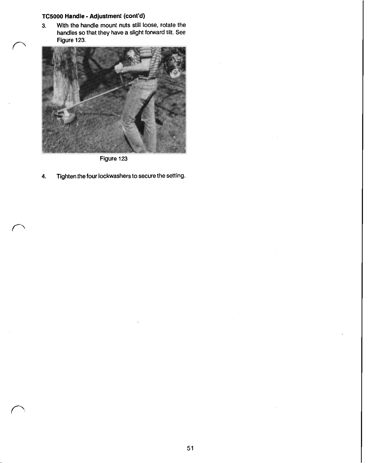
TC5000
Handle Adjustment (cont’d)
3. With the handle mount nuts still loose, rotate the
handles
so
that they have a slight forward
Figure 123.
Figure 123
4.
Tighten the four lockwashers to secure the Setting.
tilt.
See
51
Page 63
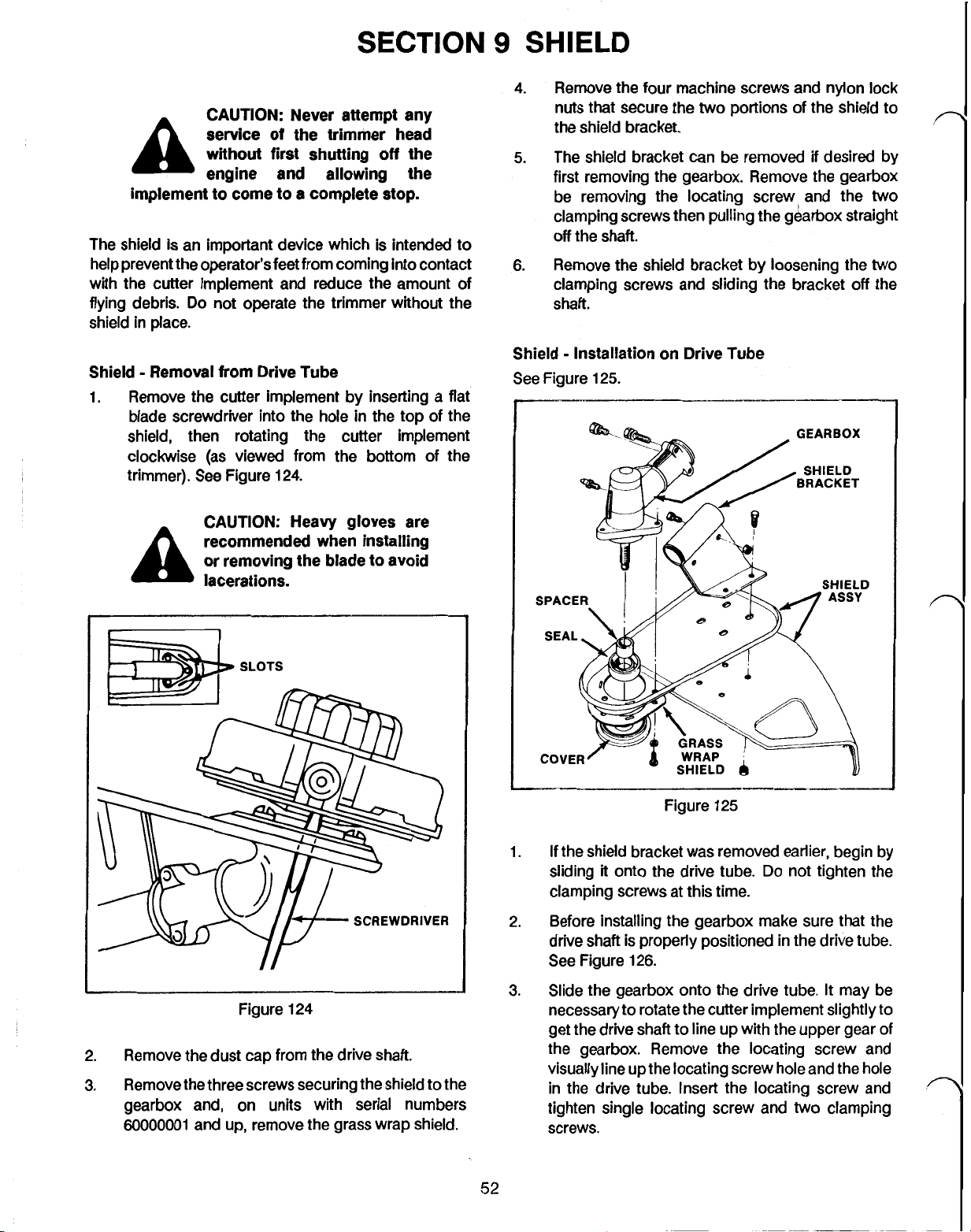
CAUTION: Never attempt any
service
A
implement to come to a complete stop.
The shield is an important device which is intended to
help prevent the operator’s feet from coming into contact
with the cutter implement and reduce the amount
flying debris.
shield in place.
without first shutting
engine and allowing the
Do
not operate
of
the trimmer head
the
trimmer without the
off
the
of
4.
Remove
nuts that secure the
the shield bracket.
5.
The shield bracket can be removed
first removing the gearbox. Remove the gearbox
be removing the locating screw, and the
clamping screws then pulling the gearbox straight
off
6. Remove the shield bracket by loosening the
clamping screws and sliding the bracket
shaft.
the
the
four machine screws and nylon lock
two
portions of
shaft.
the
shield to
if
desired by
off
two
two
the
Shield Removal from Drive Tube
1.
Remove the cutter implement by inserting a flat
blade screwdriver into the hole in the top of the
shield, then rotating the cutter implement
clockwise (as viewed from the bottom of the
trimmer). See Figure 124.
CAUTION: Heavy gloves are
recommended when installing
or removing the blade to avoid
lacerations.
Shield Installation on Drive
See
Figure 125.
SPACER
\
Figure
Tube
GEARBOX
125
Figure 124
2. Remove the dust cap from the drive shaft.
3.
Remove the three screws securing the shield to the
gearbox and, on units with serial numbers
60000001
and up, remove the grass wrap shield.
1.
If
the shield bracket was removed earlier, begin by
sliding
clamping screws at this time.
2. Before installing the gearbox make sure that the
drive shaft is properly positioned in the drive tube.
See Figure 126.
3.
Slide the gearbox onto the drive tube.
necessary to rotate the cutter implement slightly to
get the drive shaft to line up with the upper gear of
the gearbox. Remove the locating screw and
visually line up the locating screw hole and the hole
in the drive tube. Insert the locating screw and
tighten single locating screw and
screws.
it
onto the drive tube.
Do
52
not tighten the
It
may be
two
clamping
Page 64

Shield Installation
2.5
on
Drive Tube (cont’d)
CM
(1”)
Shield Mounting Cutter Knife
A
single or dual line Tap and Trim@ cutter head may be
used as the cutter implement on any
trimmers. To ensure proper line length,
on
Shield
of
the straight shaft
a
cutter knife may
be mounted to the shield.
1.
Remove the original shield from the shield support
by removing the four machine screws and lock
nuts.
2.
(TC3000
and TC4000 only). Replace the original
shield with a new shield, Tor0 part number
61-4571.
Figure 126
4.
Install the
two
portions of the shield as shown in
Figure 125. Secure with the four machine screws
and nylon
5.
On units with serial numbers
lock
nuts.
6000001
and up,
place the grass wrap shield around the drive shaft.
See Figure 125.
6. Secure the shield (and grass wrap shield on certain
units) to the gearbox with the three Phillips head
machine screws.
7. Tighten the
two
clamping screws on the shield
bracket.
8.
Install the dust
9.
Mount
the
cap
on the gearbox drive shaft.
cutter implement on the drive shaft and
tighten by inserting a flat bladed screwdriver into
the
slot
in
the top of the shield and turning the
cutter implement counterclockwise.
(TC5000)
Using the cutter knife as a template, drill
three holes in the shield. See Figure 127.
part
3. Mount the cutter knife (Toro
number
on the shield using three machine screws and
nylon lock nuts (Toro part numbers 32105-8 and
3296-2 respectively). See Figure 127.
Figure 127
61
-4540)
53
Page 65
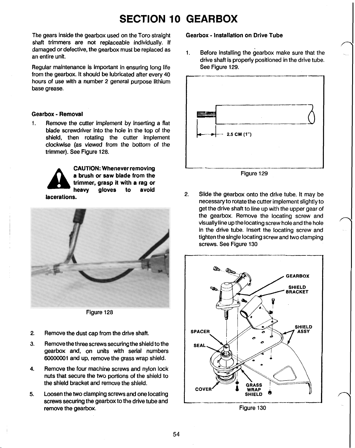
SECTION
10
GEARBOX
The gears inside the gearbox used on the Tor0 straight
shaft trimmers are not replaceable individually.
damaged or defective, the gearbox must be replaced as
an entire unit.
Regular maintenance is important in ensuring long
from the gearbox.
hours of use with a number 2 general purpose lithium
base grease.
Gearbox Removal
1.
Remove the cutter implement by inserting a flat
blade screwdriver into the hole in the top of the
shield, then rotating the cutter implement
clockwise (as viewed from the bottom of the
trimmer).
A
lacerations.
It
should be lubricated after every
See
Figure 128.
CAUTION:
a
brush or saw blade
trimmer, grasp
heavy gloves
Whenever removing
from
it
with a rag or
to
the
avoid
If
life
40
Gearbox Installation on Drive Tube
1. Before installing
drive shaft is properly positioned in the drive tube.
See Figure 129.
2. Slide the gearbox onto the drive tube.
necessary to rotate the cutter implement slightly to
get the drive shaft to line up
the gearbox. Remove the locating screw and
visually line
in the drive tube. Insert the locating screw and
tighten the single locating screw and
screws. See Figure 130
the
gearbox make sure that the
2.5
CM
(1")
with
the upper gear of
up
the locating screw hole and the hole
two
It
may be
clamping
Figure 128
2. Remove the dust cap from the drive shaft.
3. Remove the three screws securing the shield to the
gearbox and, on units with serial numbers
6OOOOOO1 and up, remove the grass wrap shield.
4.
Remove the four machine screws and nylon lock
nuts that secure the
the shield bracket
5.
Loosen the
screws securing the gearbox to the drive tube and
remove the gearbox.
two
two
portions of the shield to
and
remove the shield.
clamping screws and one locating
54
--
Figure 130
GEARBOX
SHIELD
BRACKET
Page 66

Gearbox Installation On Drive Tube (cont’d)
3.
Install the
Figure
and nylon
4.
On units with serial numbers
two
portions
130.
Secure with the four machine screws
lock
nuts.
of
the shield as shown in
6000001
and up,
place the grass wrap shield around the drive shaft.
See Figure
5.
Secure the shield (and grass wrap shield on sertain
130.
units) to the gearbox with the three Phillips head
machine screws.
6.
Tighten the
two
clamping screws on the shield
bracket.
8.
Install the dust cap on the gearbox drive shaft.
9.
Mount the cutter implement on the drive
shaft
and
tighten by inserting a flat bladed screwdriver into
the slot in the top
of
the shield and turning the
cutter implement counterclockwise.
Gearbox Seal Removal
A
seal is
used
in the lower portion of the gearbox to keep
contaminants from entering as well as to retain grease
within the gearbox.
CAUTION:
Whenever removing
a brush or saw blade from
trimmer, grasp
it
with a rag a
heavy gloves to avoid
lacerations.
2.
Remove the dust cap from the drive shaft.
3.
Remove the sleeve from the cutter head drive shaft
by grasping with a pliers and pulling straight
See Figure
132.
the
off.
1.
Remove the cutter implement by inserting a flat
bladed screwdriver into the hole in the top of the
shield, then rotating the cutter implement
clockwise (as viewed from the bottom of the
trimmer). See Figure
131.
SCREWDRIVER
4.
Figure
Remove the seal.
132
Gearbox Seal Installation
1.
Press the new seal into the gearbox with hollow
portion of the seal facing the gearbox. Use a
inch socket to press
2.
Lubricate the sleeve with grease and slide on the
splined shaft until
3.
Install the dust cap on the gearbox drive shaft.
4.
Mount the cutter implement on the drive shaft and
it
in.
it
bottoms
out.
tighten by inserting a flat bladed screwdriver into
the slot in the top of the shield and turning the
cutter implement counterclockwise.
11/4
Figure
131
55
Page 67

SECTION
The drive tube and shaft assemblies used on the TC3000,
TC4000
is made of steel and is hardened on both ends. For
positive engagement with the clutch and gearbox, a nine
tooth spline is used on both ends.
The drive tubes vary slightly in dimension between the
three straight shaft trimmers, but are similarly
constructed. Each use an aluminum tube that houses
five oil impregnated bushings. These bushings are
positioned approximately every nine inches inside the
shaft. They are supported by rubber grommets that hold
them in place. See Figure 133.
and TC5000 utilize a common shaft. This shaft
GROMMET
2.3
CM
(9)-
11
BUSHING
DRIVE SHAFT AND TUBE
2.
Loosen the
the drive tube, then pull the gearbox and shield
assembly
3. Pull the drive shaft from the tube being careful not
to damage the splined end.
4. Inspect the shaft for excessive wear and evidence
of overheating.
necessary, replace both the shaft and the drive
tube.
Drive Shaft Installation
1. Grease the splined ends of the shaft to ensure that
they are easy to remove
necessary.
the shaft with motor
2.
Slide the shaft into the drive tube until
the splined clutch shaft and bottoms out. The shaft
should extend approximately
the drive tube when
135.
two
shield bracket screws closest to
off
the drive tube.
If
it appears replacement is
if
future service is
Also,
lubricate the smooth portion of
oil.
2.5
cm (1 inch) from
it
is fully seated. See Figure
it
engages
n
Figure 133
Neither the drive tube nor the drive shaft is serviceable.
If
either is worn to the point where the shaft begins to
vibrate excessively, both should be replaced.
DRIVE
Drive Shaft Removal
1. Remove the locating screw and loosen the two
SHAFT
clamping screws on the cutter head gearbox. See
Figure 134.
a
2.5
CM
(1")
Figure 135
3. Remove the locating screw from the gearbox and
slide the gearbox and shield assembly onto the
drive tube.
4. Visually align the locating screw and the hole in the
drive tube, then install and tighten the locating
screw.
5.
Tighten the two gearbox clamping screws and the
shield bracket screws to secure the assembly.
DRIVE TUBE
Figure 134
Drive Tube Removal
1. Remove the engine as described under Engine
Removal from Drive Tube, page
56
40.
Page 68

Drive Tube Removal (cont'd)
2.
Remove the handle as described under TC3000
Handle Removal from Drive Tube, page
TC4000 Handle Removal from Drive Tube,
page
48,
or TC5000 Handle Removal from
Drive Tube, page
3.
Remove the control and grip as described under
49.
Grip Removal, page 46.
4.
Remove the gearbox locating screw then loosen
the four other screws denoted by arrows in Figure
136.
48,
7.
Inspect the tube for excessive wear, bends or
excessive heat. Replace
NOTE:
shaft
If
it
is necessary
should also be closely inspected as
if
necessary.
to
replace the tube, the
also require replacement.
Drive Tube Installation
1.
Mount the control and grip on the drive tube as
described under Grip Installation, page
2.
Mount the engine on the drive tube as described
under Engine Installation on Drive Tube, page
45.
3.
Grease the splined ends of the drive shaft
easy disassembly in the future. Lubricate the shaft
with motor oil, and install into the drive tube.
Approximately
the end of the drive tube once
4.
Mount the gearbox and shield assembly by first
2.5
cm
(1
inch) will extend beyond
it
is firmly seated.
removing the locating screw. Push the gearbox
and shield assembly onto the tube and visually
align the locating holes.
47.
to
ensure
it
may
Figure 136
5.
Remove the gearbox and shield assembly.
6. Remove the drive shaft from the tube being careful
to
damage the splined ends of the shaft.
not
5.
Secure the gearbox and shield by tightening the
four screws denoted by arrows in Figure 36.
6. Mount the handle as described under TC3000
Handle Installation on Drive Tube, page
TC4000 Handle Installation on Drive Tube,
page
49,
or TC5000 Handle Installation on
Drive Tube, page
50.
48,
57
Page 69
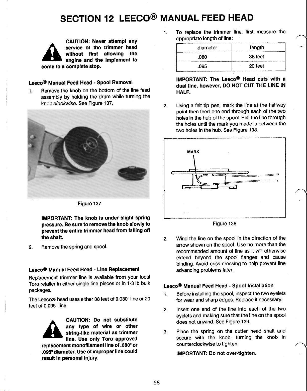
SECTION
CAUTION: Never attempt any
service of the trimmer head
without first allowing the
A
come to a complete stop.
engine and the implement to
12
LEECO(R)
MANUAL FEED HEAD
To replace the trimmer line, first measure the
1.
appropriate length of line:
.095
n
20
--
feet
Leeco(R) Manual Feed Head Spool Removal
1,. Remove the knob on the bottom of the line feed
assembly by holding the drum while turning the
knob
clockwise.
IMPORTANT: The knob is under slight spring
pressure. Be sure to remove
prevent the entire trimmer head from falling
the shaft.
2.
Remove the spring and spool.
Leeco(R) Manual Feed Head Line Replacement
Replacement trimmer line is available from your local
Toro retailer in either single line pieces or in 1-3 Ib bulk
packages.
The Leeco@ head uses either 38
feet
of 0.095”
line.
A
replacement monofilament line of
.095"
diameter. Use of improper line could
result
in
personal injury.
See Figure 137.
Figure 137
the
knob slowly to
feet
of
0.080"
line Or
CAUTION:
any type
string-like material as trimmer
line. Use only Tor0 approved
Do
not substitute
of
wire
or
.080”
other
or
off
20
IMPORTANT: The Leeco(R) Head cuts with a
dual line, however,
HALF.
Using a
2.
point then
holes in the hub of the
the holes until the mark you made is between the
two holes in the hub.
felt
tip pen, mark the line at the halfway
feed
-----
MARK
2.
Wind the line on the spool in the direction of the
arrow shown on the spool. Use no more than the
recommended amount of line as
extend beyond the spool flanges and cause
binding. Avoid criss-crossing to help prevent line
advancing problems later.
Leeco(R) Manual Feed Head Spool Installation
1.
Before installing the spool, inspect the two eyelets
for wear and sharp edges. Replace
2.
Insert one end of the line into each of the two
eyelets and making sure that the line on the
does not unwind. See Figure 139.
3. Place the spring on the cutter head shaft and
secure with the knob, turning the knob in
counterclockwise to tighten.
IMPORTANT:
DO
NOT CUT THE LINE IN
one end through each of the two
spool.
Pull the line through
See
Figure
-I-
Do
not over-tighten.
138.
it
will otherwise
if
necessary.
spool
Page 70

Leeco(R) Manual Feed Head Spool Installation
(cont'd)
Figure 139
head assembly from the drive shaft.
3. Hold the drum stationary while turning the knob
clockwise to remove the knob. Hold onto the knob
firmly as
it
is under slight spring pressure. Remove
the knob, spring and spool.
Leeco(R) Manual Feed Head Inspection
1. Inspect the drum, spool and knob for any damage
which may impair their operation. Replace as
required.
2.
Inspect the eyelets for wear and sharp edges.
Replace
if
necessary. They can be replaced
individually.
3.
Remove the cutter head shaft from the drum and
inspect for damage. Replace
if
necessary.
Leeco(R) Manual Feed Head Reassembly
1.
Push the
drum making sure that they bottom
two
eyelets into the
slots
provided in the
out.
4. Cut
off
any excess line
so
that
it
does not strike the
shield when fully extended.
Leeco(R) Manual Feed Head Disassembly
the
1. Remove
blade screwdriver into one of the
top of the shield.
head
head assembly by inserting a medium
two
See
Figure 140. This prevents the
from rotating.
slots in the
2.
Install the cutter head shaft into the drum as shown
in Figure 141.
ADAPTER
SHAFT
2.
Turn the head
Figure 140
clockwise
SCREWDRIVER
to loosen and remove the
59
Figure 141
3.
Wind line onto spool
as
described under Leeco(R)
Manual Line Feed Head Line Replacement,
page
58.
4.
Install the spool and line assembly into the drum,
threading one line through each of the eyelets.
Figure 142.
See
Page 71

Leeco(R) Manual Feed Head Reassembly (cont’d)
n
Figure
Place the spring on the cutter head shaft and
5.
142
secure with the knob.
NOTE:
Rotate the knob counterclockwise to
tighten.
Reinstall the head assembly onto the drive shaft by
6.
turning counterclockwise. Insert a medium blade
screwdriver into one
140
to prevent the drive shaft from rotating.
Cut
off
7.
any excess line
of
the slots shown in Figure
so
that
it
does not strike the
shield.
60
Page 72

SECTION
CAUTION: Never attempt any
service of the trimmer head
A
implement to come to a completer
Kaaz(R) Manual Feed Head Disassembly
1.
Grasp the cutter head to prevent
remove the knob by turning
Figure
without first shutting
engine and allowing the
143.
13
it
from turning and
it
clockwise.
KAAZ(R)
off
the
stop.
See
MANUAL
Kaaz(R) Manual Feed Head Line Replacement
Replacement trimmer line is available from your local
Tor0 retailer in either single pieces or in 1-3 Ib. bulk
packages.
A
replacement monofilament line of
.095”
result
1.
To replace the trimmer line, first measure the
appropriate length of line:
FEED HEAD
CAUTION:
any type of wire
string-like material as trimmer
line. Use only Tor0 approved
diameter. Use of improper line could
in
personal injury.
Do
not substitute
or
.080'
other
or
SLOTS
I
Figure
2.
Pull the drum and spool assembly from the drive
shaft.
143
SCREWDRIVER
20
feet
IMPORTANT The Kaaz(R) Head cuts with a dual
line, however,
2.
Using a
halfway point.
3.
Thread the line through the retainer shown in
Figure 144 until the mark and the retainer are
aligned.
MARK
DO
NOT CUT THE LINE IN
felt
tip pen, mark the trimmer line at the
Figure 144
HALF.
3.
Separate the drum, spool and spring being careful
not to lose the
parts and replace as necessary.
NOTE: Inspect the internal diameter of the eyelets
to ensure they are smooth. Burrs or sharp edges
could cause the line to break at the eyelets.
two
eyelets. Inspect for damaged
61
4. Wind the
arrow. Avoid criss-crossing the line as it may lead
to line advancing problems later.
NOTE:
smaller flange as this may create binding.
line
on the spool in the direction
Do
not allow the line to extend beyond the
of
the
Page 73

Kaaz(R) Manual Feed Head Reassembly
1.
Prepare for reassembly by placing the spring on
the drum as shown in Figure
145.
SPOOL
Thread one eyelet onto each end of the trimmer
2.
line and position the spool (with the small flange
toward the spool) above the drum.
Push the eyelets into the slots in the drum making
3.
sure that they bottom out.
Place the spool and drum assembly on the cutter
4.
head shaft with the spool facing the shield.
Secure with the knob by turning counterclockwise.
5.
IMPORTANT
spool
flange line
Make sure the ratchets on the
up
with the recesses in the
drum before tightening.
Figure
145
SPRING
EYELET
Adjust the length of the line
6.
so
that it does not
extend beyond the flange edge of the shield.
Page 74
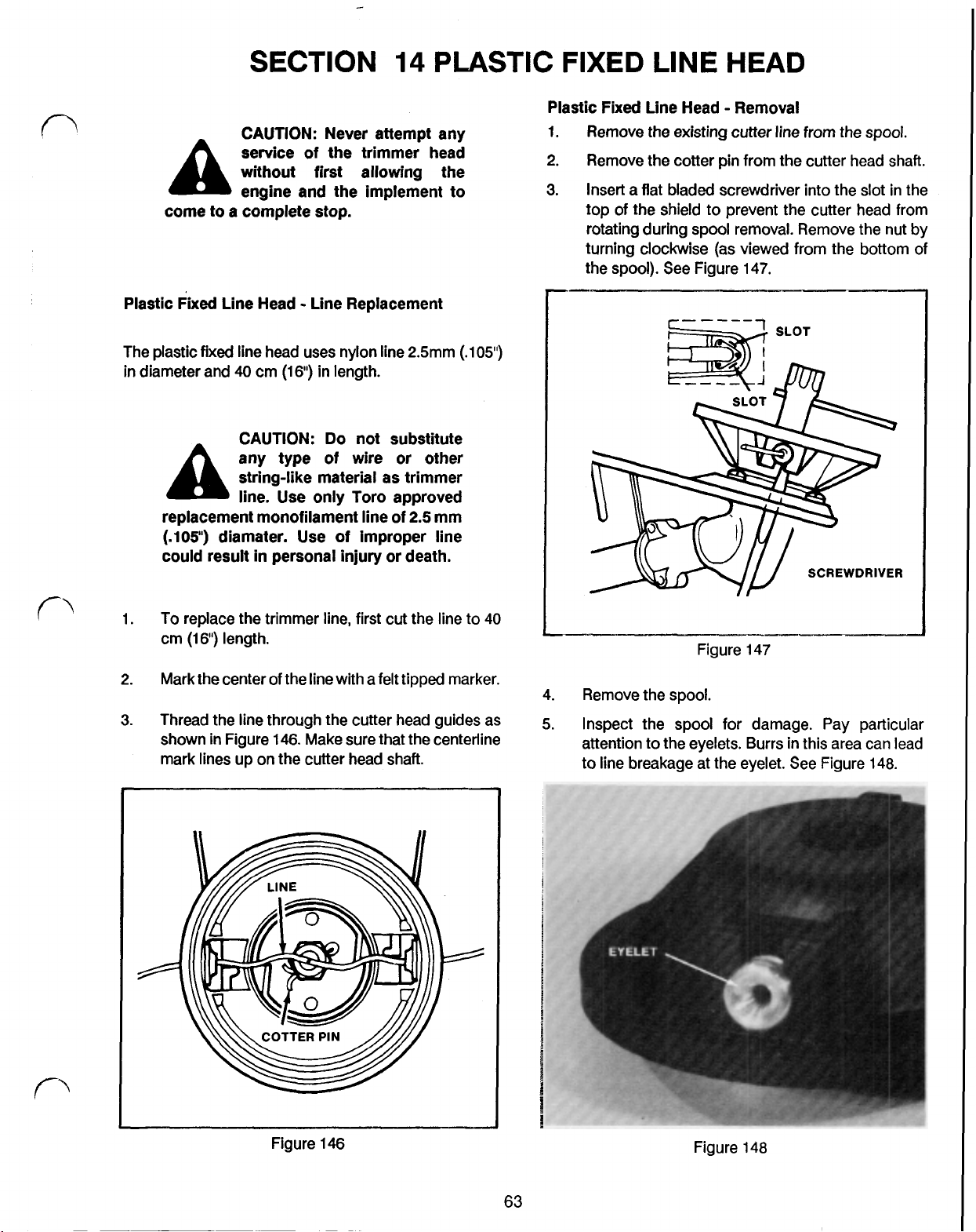
SECTION
CAUTION: Never attempt any
of
service
without first allowing the
A
come to a complete stop.
Plastic Fixed Line Head Line Replacement
engine and the implement to
the trimmer head
14
PLASTIC
2.
3.
FIXED
Plastic Fixed Line Head Removal
1. Remove the existing cutter line from the spool.
Remove the cotter pin from the cutter head shaft.
Insert a flat bladed screwdriver into the slot in the
top of
rotating during spool removal. Remove the nut by
turning clockwise (as viewed from the bottom of
the spool). See Figure 147.
LINE
the
shield to prevent the cutter head from
HEAD
The plastic
in
diameter and
1.
2.
3.
fixed
line head uses nylon line 2.5mm (.105")
40
cm (16') in length.
CAUTION:
any type of wire or other
string-like material as trimmer
A
replacement monofilament line of
(.105”)
could result
To
replace the trimmer line, first cut the line to 40
cm (16') length.
Mark the center of the line with a
Thread the line through the cutter head guides as
shown in Figure 146. Make sure that the centerline
mark lines up on the cutter head shaft.
line. Use only Tor0 approved
diameter. Use of improper line
in
personal injury or death.
Do
not substitute
felt
2.5
tipped marker.
mm
SCREWDRIVER
Figure 147
4.
Remove the spool.
5.
Inspect the spool for damage. Pay particular
attention to the eyelets. Burrs in this area can lead
to line breakage at the eyelet. See Figure 148.
Figure 146
Figure 148
63
Page 75
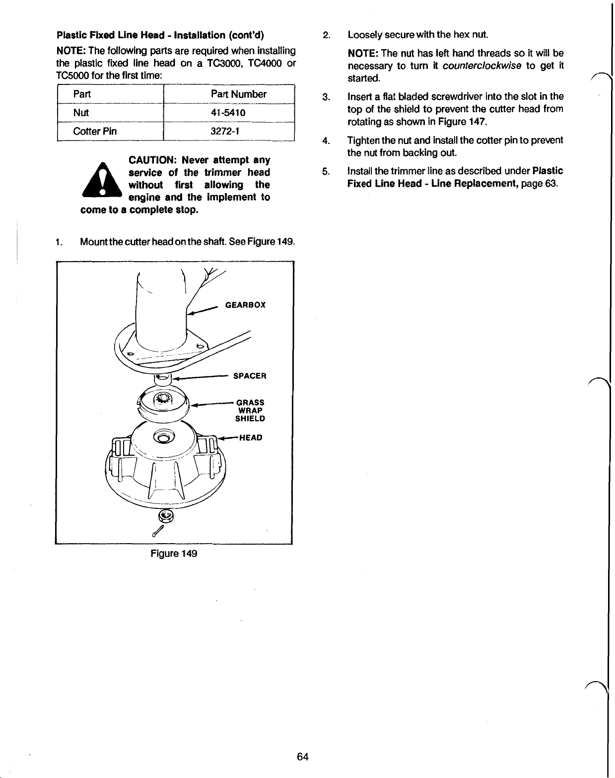
Plastic
NOTE: The following parts are required when installing
the plastic fixed line head on a
TC5000
1.
Fixed
Line Head Installation (cont’d)
for the first time:
Cotter
Pin
CAUTION: Never attempt any
service
A
come to a complete stop.
Mount the cutter head on the shaft.
without first allowing the
engine and the implement to
of
TC3000,
Part Number
41-5410
3272-1
the trimmer head
See
Figure
or
149.
2.
Loosely secure with the hex nut.
NOTE: The nut has left hand threads
necessary to turn
started.
3.
Insert a flat bladed screwdriver into the slot in the
top of the shield to prevent the cutter head from
rotating as shown in Figure
4.
Tighten the nut and install the cotter pin to prevent
the nut from backing out.
5.
Install the trimmer line as described under Plastic
Fixed Line Head Line Replacement, page
it
counterclockwise
147.
so
it will be
to get
it
63.
Figure
149
GRASS
WRAP
SHIELD
HEAD
64
Page 76

SECTION
15
METAL FIXED LINE HEAD
2.
Remove the cotter pin from the cutter head shaft.
CAUTION: Never attempt any
service of the trimmer head
without first allowing the
A
come to a complete stop.
Metal
Fixed
The aluminum fixed
or 3.3 mm (.130") line. Because of the added load put on
the engine when using the thicker line, be sure to cut the
line to the proper length:
1.
To
replace the trimmer line, first cut the line to the
proper length mentioned above.
2.
Mark the center of the line with a felt tipped marker.
3. Thread the line through the cutter head guides as
shown in Figure 150. Make sure that the centerline
mark lines up on the cutter head shaft.
engine and the implement to
Line Head Line Replacement
line
head uses either
2.5
mm (.105')
3. Insert a flat bladed screwdriver into the slot in the
top of the shield to prevent the cutter head from
rotating during spool removal. Remove the nut by
turning
the spool). See Figure 151.
I
clockwise
Figure 151
(as viewed from the bottom of
SCREWDRIVER
Figure 150
1.
Center
of
line
2.
Outer projections
IMPORTANT While
lines with the metal fixed line head, best cutting
results are obtained by using only one line.
it
3.
Position
in
slot
is
possible to use two
4.
Remove the spool being careful not to lose the
insert.
5.
Inspect the spool for damage. Pay particular
attention to the area where the line exits the spool.
Burrs in this area can lead to premature line
breakage at the point where
Figure 152.
it
exits the spool.
See
Metal
Fixed
Line Head Removal
1. Remove the existing cutter line from the spool.
65
1.
Cotter
Figure 152
pin
2.
Check
for
burrs
Page 77
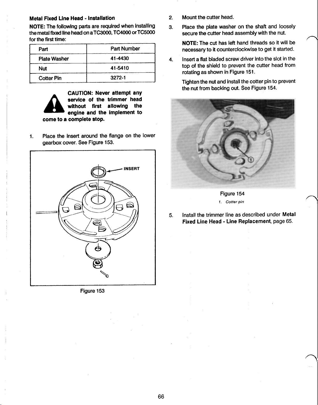
Metal Fixed Line Head Installation
NOTE: The following parts are required when installing
fixed
the metal
for the first time:
Part
Plate Washer
Nut
Cotter Pin
A
come to
1. Place the insert around the flange on the lower
gearbox cover. See Figure 153.
line head on a TC3000,
CAUTION: Never attempt any
service
without first allowing the
engine and the implement to
a
complete stop.
of
the trimmer head
TC4000
Part Number
41-4430
41-5410
3272-1
or TC5000
Mount the cutter head.
2.
Place the plate washer on the shaft and loosely
3.
secure the cutter head assembly with the nut.
NOTE: The cut
necessary to
Insert a flat bladed screw driver into the slot in the
4.
top of the shield to prevent the cutter head from
rotating as shown in Figure 151.
Tighten the nut and install the cotter pin to prevent
the nut from backing out. See Figure 154.
has
left hand threads
it
counterclockwise to get
so
it
it
will be
started.
Figure 153
Figure 154
7.
Cotter
pin
5.
Install the trimmer line as described under Metal
Fixed Line Head Line Replacement, page
65.
Page 78

SECTION
CAUTION: Never attempt
any service of the trimmer
A
and allowing the implement to come to a
complete stop.
TAP AND TRIM@ LINE REPLACEMENT
Tap and Trim@ Spool Removal
1. Insert a medium blade screwdriver into one of the
two slots on the bottom of the spool and twist 1/4
turn to release the spool. See Fig. 155.
head without first
shutting
off
16
the engine
TAP
AND
2.
TRIM@
1. To wind replacement line on the spool, first hook
one end of the line into the keyhole slot in the top
flange of the spool. See Fig. 156.
Wind the line on the spool in the direction
arrow. Use no more than
otherwise extend beyond the spool flanges and
cause binding. Avoid criss-crossing to help
prevent line advancing problems later.
HEAD
Figure 156
38
feet of line as
of
it
the
will
Figure 155
2.
Remove the spool.
Tap and Trim@ Spool Line Replacement
Prewound Tap and Trim@ spools are available through
If
your local Toto retailer.
down to Tap and Trim@ Spool Installation below.
While prewound
economical approach is to wind new line on the existing
spool. Tor0 monofilament line can be purchased in bulk
under
Tor0
part
number 41-6830 for one pound or
41-6830
for 3 pounds.
A
Use only Tor0 approved replacement
monofilament line of
of
improper line
injury.
using a prewound spool, skip
spools
are convenient, a more
CAUTION:
substitute any type of wire
or other string-like
material as trimmer line.
.080”
could
result in personal
Do
diameter. Use
not
3.
Hook the end of the line in one
provided in the upper flange
the line tight while installing the spool.
4. Cut the line protruding from
only 1/2 inch remains.
Tap and Trim@ Spool Installation
1. Align the keys molded into the core with the eyelet
on the drum. It may be necessary to depress the
core and rotate to get the keys to line up properly.
See Fig. 157
of
the
of
the spool to keep
the
keyhole slot
two
so
slots
that
\
Figure 157
I
67
Page 79
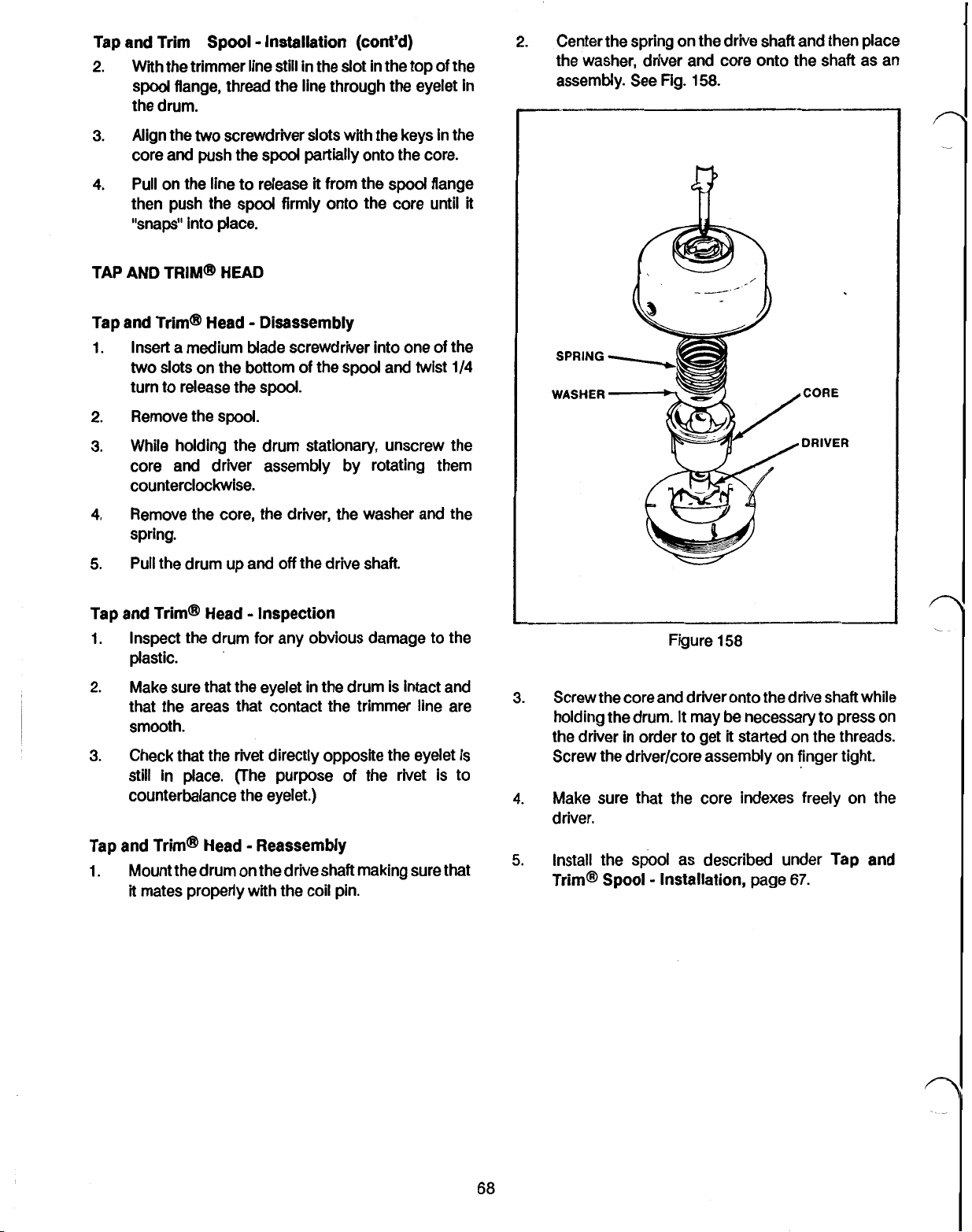
Tap and Trim Spool Installation (cont'd)
2.
With the trimmer line still in the slot in the top of the
spool
flange, thread the line through the eyelet in
the drum.
3.
Align the two screwdriver slots with the keys in the
spool
core and push the
4.
Pull
on the line to release
partially onto the core.
it
from the
spool;
then push the spool firmly onto the core until
"snaps" into place.
TAP AND TRIM@ HEAD
Tap and Trim@ Head Disassembly
Insert a medium Made screwdriver into one of the
1.
two slots on the bottom of the spool and twist
turn to release the
Remove the
2.
While holding the drum stationary, unscrew the
3.
spool
spool
core and driver assembly by rotating them
counterclockwise.
flange
1/4
2.
Center the spring on the drive shaft and then place
the washer, driver and core onto the shaft
assembly. See Fig.
it
SPRING
WASHER
158.
CORE
CORE
DRIVER
DRIVER
as
an
Remove the core, the driver,
4.
the
washer and the
spring.
Pull the drum up and
5.
off
the drive shaft.
Tap and Trim@ Head Inspection
1.
Inspect the drum for any obvious damage to the
plastic.
2.
Make sure that the eyelet in the drum
that the areas that contact
the
is
trimmer line are
smooth.
3.
Check that the rivet directly opposite the eyelet is
still
in
place. (The purpose of the rivet is to
counterbalance the eyelet.)
Tap and Trim@ Head Reassembly
1.
Mount the drum on the drive shaft making sure that
it
mates properly with the coil pin.
intact and
Figure
3.
Screw the core and driver onto
holding the drum.
the driver in order to get
158
the
drive shaft while
It
may be necessary to press
it
started on the threads.
Screw the driver/core assembly on finger tight.
4.
Make sure that the core indexes freely on the
driver.
5.
Install the spool as described under Tap and
Trim@
Spool
Installation, page
67.
on
Page 80

SECTION
Tor0 offers
straight shaft trimmer line. The eight tooth blade is
designed for cutting brush and heavy weeds up to about
1.3 cm (1/2 inches). The eighty tooth blade should be
used in heavy brush and
(3/4") are present.
When using either blade, a harness is required to help
maintain adequate control.
Metal Blade Removal
1. Remove the cotter pin from the cutter head drive
2. Insert a flat bladed screwdriver into the slot in the
top of the shield to prevent the blade from rotating
two
20 cm
CAUTION: Never attempt any
service of the trimmer head
A
implement to come to a complete stop.
shaft.
during removal. See Figure 159.
without first shutting
engine and allowing
(8
inches) blades that
if
scrub trees greater than 2 cm
off
the
the
fit
the
Blade Adapter Kit for Gas Trimmer, Tor0 part number
41-4440.
1. Mount the blade on the cutter head shaft. There
fit
should be a perfect
cover flange and the hub on the blade.
IMPORTANT
with the teeth pointing
Make sure that they are pointing as shown
Figure
160.
It
between the lower gearbox
is important to install the blade
in
the correct direction.
in
SLOTS
Figure 159
3. Remove the nut securing the blade by turning
clockwise (the nut uses left hand threads).
4. Remove the blade adapter and blade. Inspect the
blade for damage or cracks and replace
necessary.
Figure
2.
Place the blade adapter on the shaft and loosely
secure with the hex nut.
NOTE: The hex nut uses
therefore must be turned counterclockwise to
tighten.
3.
Insert a flat bladed screwdriver into the slot in the
top of the shield to prevent the blade from turning
while tightening the nut.
CAUTION: The
metal blades are very sharp.
if
recommended when installing
or removing the blade.
160
left
hand threads and
See
Figure 159.
teeth
gloves are
on
the
Metal Blade Installation
Note: If you are installing either the saw blade or the
brush blade for the first time, you will require the Metal
4. Insert a cotter pin in the shaft to prevent the hex
nut
from backing
out.
69
Page 81

SECTION
Standard and Deluxe Harness Assembly
1.
(TC3000
control. See Figure 161.
and
TC4000)
Slip the ring into the throttle
18
HARNESSES
n
I
Figure 162
Figure 161
(TC5000)
the tube approximately
isomount housing. Secure with the
machine screw. See Figure 162.
3.
Adjust the harness
rotates in a nearly level plane with a slight forward
tilt.
4.
(Deluxe Harness Only) Fasten the belt by
threading the loose end through the buckle.
Figure 163.
Mount the clamp and ring assembly onto
15
cm (6 inches) below the
so
that the trimmer line or blade
nut
and
See
Figure 163
Page 82

SECTION
19
Spark
Arrestor
Muffler
Spark arrestor mufflers are available for the straight shaft
trimmers. These mufflers use a metal screen at the
muffler
chamber.
They are recommended when trimming in dry areas and
may
Spark Arrestor Muffler Removal
1. Remove the three screws that secure the muffler
to
prevent sparks from exiting
be
required by state or
cover to the engine and remove the cover.
Figure
164.
local
laws.
the
muffler
See
3.
Spark Arrestor Muffler Maintenance
After every
muffier body should be removed and soaked in a
commercial carbon remover per the manufacturer’s
instructions.
1.
2.
Install the new muffler cover with three Phillips
head screws.
50
hours of use, the arrestor screen and
Remove the muffler as described under Spark
Arrestor Muffler Removal, page 71.
Remove the
arrestor to the muffler. See Figure 165
two
screws securing the spark
Figure 164
2.
Remove the
engine and the Phillips head screw near the fuel
tank. Remove the muffler.
3.
Remove the
the arrestor screen
screen.
Spark Arrestor Muffler Installation
1. If installing the spark arrestor muffler for the first
time, remove the original muffler cover and muffler.
2.
Place the muffler gasket on the studs and install
the muffler. Secure with the
Phillips head screw.
two
nuts securing the muffler to
two
Phillips head screws that secure
to
the muffler and remove the
two
hex nuts and
the
the
3.
Soak the muffler and the spark arrestor screen in
a commercial carbon remover per the
manufacturer’s instructions.
4.
Blow out any loose carbon with compressed air.
IMPORTANT Before reinstalling the muffler, be sure
to
remove
damage may result.
5.
Reinstall the muffler as described under Spark
Arrestor Muffler Installation, page 71.
all
loose carbon particles
or
engine
71
 Loading...