

Page 1

FormNo.3392-628RevA
T42404-WheelDrive5-Plex
MowerTractionUnit
ModelNo.02750—SerialNo.315000001andUp
Registeratwww.T oro.com.
OriginalInstructions(EN)
*3392-628*A
Page 2

ThisproductcomplieswithallrelevantEuropeandirectives;
fordetails,pleaseseetheseparateproductspecicDeclaration
ofConformity(DOC)sheet.
Introduction
Thismachineisaride-on,cutterhead-bladelawnmower
intendedtobeusedbyprofessional,hiredoperatorsin
commercialapplications.Itisprimarilydesignedforcutting
grassonparks,sportselds,caravanparks,cemeteriesand
commercialgrounds.Itisnotdesignedforcuttingbrushor
foragriculturaluse.
Readthisinformationcarefullytolearnhowtooperateand
maintainyourproductproperlyandtoavoidinjuryand
productdamage.Youareresponsibleforoperatingthe
productproperlyandsafely.
YoumaycontactTorodirectlyforproductandaccessory
information,helpndingadealer,ortoregisteryour
productatToroCommercialProductsServiceDepartment
Spellbrook,Bishop’sStortford,CM234BU ,England,
+44(0)1279603019,Email:uk.service@toro.com.
Wheneveryouneedservice,genuineT oroparts,oradditional
information,contactanAuthorizedServiceDealerorToro
CustomerServiceandhavethemodelandserialnumbersof
yourproductready.Themodelandserialnumbersareona
platemountedontheleftsideoftheframeunderthefoot
rest.Writethenumbersinthespaceprovided.
ModelNo.
SerialNo.
Thismanualidentiespotentialhazardsandhassafety
messagesidentiedbythesafetyalertsymbol(Figure1),
whichsignalsahazardthatmaycauseseriousinjuryordeath
ifyoudonotfollowtherecommendedprecautions.
Figure1
1.Safetyalertsymbol
Thismanualuses2wordstohighlightinformation.
Importantcallsattentiontospecialmechanicalinformation
andNoteemphasizesgeneralinformationworthyofspecial
attention.
©2014—TheToro®Company
8111LyndaleAvenueSouth
Bloomington,MN55420
Contactusatwww.Toro.com.
2
PrintedintheUK
AllRightsReserved
Page 3

Contents
Safety...........................................................................4
SafeOperatingPractices...........................................4
ToroRidingMowerSafety........................................6
SoundPowerLevel..................................................7
SoundPressureLevel...............................................7
VibrationLevel.......................................................7
SafetyandInstructionalDecals.................................8
ProductOverview.........................................................12
Controls...............................................................13
BrakingSystem...................................................14
WarningSystems................................................18
IndicatorLights..................................................19
Specications........................................................20
Attachments/Accessories........................................20
Operation....................................................................21
ThinkSafetyFirst...................................................21
CheckingtheEngine-OilLevel.................................21
AddingFuel...........................................................21
UsingtheOperatorPlatformLatching
Mechanism........................................................22
UnderstandingtheOperatorPresence
Controls............................................................23
StartingandStoppingtheEngine..............................24
AdjustingtheHeight-of-Cut....................................25
ControllingthePositionofanIndividualCutting
Unit..................................................................25
DualLiftCongurationControl...............................25
EngagingtheCuttingUnitDrive..............................26
UsingtheWeight-Transfer/Traction
Assistance..........................................................26
FoldingtheROPS..................................................26
JackingPoints........................................................27
ClearingtheCuttingCylinders..................................27
OperatingTips......................................................28
Maintenance.................................................................29
RecommendedMaintenanceSchedule(s)......................29
DailyMaintenanceChecklist....................................30
Pre-Maintenance...................................................31
ServiceIntervalChart.............................................32
Lubrication...............................................................33
GreasingtheBearings,Bushings,andPivots...............33
EngineMaintenance..................................................34
CheckingtheEngineOverheatWarning
System..............................................................34
ServicingtheAirCleaner.........................................34
CheckingtheEngine-OilLevel.................................34
ChangingtheEngineOilandFilter...........................35
FuelSystemMaintenance...........................................36
DrainingtheFuelTank...........................................36
CheckingtheFuelLinesandConnections..................36
ReplacingtheFuelFilterCanister..............................36
BleedingtheFuelSystem.........................................36
BleedingAirfromtheFuelInjectors..........................37
ElectricalSystemMaintenance....................................37
ServicingtheBattery...............................................37
DriveSystemMaintenance.........................................38
ChangingtheTransmission-OilFilter........................38
CheckingtheRearWheelAlignment.........................38
CheckingtheTirePressure......................................39
CheckingtheTorqueoftheWheelNuts.....................39
CoolingSystemMaintenance......................................39
CheckingtheCoolingSystem...................................39
RemovingDebrisfromtheCoolingSystem................40
BrakeMaintenance....................................................40
TowingtheMachine...............................................40
RecommissioningtheMachineafterTowing...............41
BeltMaintenance......................................................42
CheckingtheConditionandTensionofthe
AlternatorBelt...................................................42
ControlsSystemMaintenance.....................................42
CheckingtheForward/ReverseTravelPedal
Action...............................................................42
CheckingtheOperator-PresenceSeatSwitch..............42
CheckingtheCutterDriveInterlockSwitch................42
CheckingtheParkingBrakeInterlockSwitch..............42
CheckingtheTransmissionNeutralInterlock
Switch...............................................................43
CheckingtheDiverterValves...................................43
HydraulicSystemMaintenance....................................43
ServicingtheHydraulicSystem.................................43
CheckingtheHydraulicFluid...................................44
ChangingtheHydraulicOilReturnFilter...................45
CheckingtheHydraulicOilOverheatWarning
System..............................................................45
CheckingtheHydraulicLinesandHoses....................45
CuttingUnitMaintenance...........................................46
Storage........................................................................46
PreparingtheTractionUnitforStorage.....................46
PreparingtheEngineforStorage..............................46
Troubleshooting...........................................................47
3
Page 4

Safety
ThismachinehasbeendesignedinaccordancewithEN
ISO5395:2013.
Improperlyusingormaintainingthemachinecanresult
ininjury.T oreducethepotentialforinjury,complywith
thesesafetyinstructionsandalwayspayattentiontothe
safetyalertsymbol,whichmeansCaution,Warning,or
Danger—personalsafetyinstruction.Failuretocomply
withtheinstructionmayresultinpersonalinjuryor
death.
SafeOperatingPractices
•Replacedamagedorwornsilencers/mufers.
•Onlyuseaccessoriesandattachmentsapprovedbythe
manufacturer.
•Beforeusing,alwaysvisuallyinspecttoseethattheblades,
bladeboltsandcutterassemblyarenotwornordamaged.
Replacewornordamagedbladesandboltsinsetsto
preservebalance.
•Onmulti-bladedmachines,takecareasrotatingoneblade
cancauseotherbladestorotate.
•Checkthattheoperator'spresencecontrols,safety
switchesandshieldsareattachedandfunctioning
properly.Donotoperateunlesstheyarefunctioning
properly.
Training
•ReadtheOperator'sManualandothertrainingmaterial
carefully.Befamiliarwiththecontrols,safetysigns,and
theproperuseoftheequipment.
•Neverallowchildrenorpeopleunfamiliarwiththese
instructionstouseorservicethemachine.Local
regulationsmayrestricttheageoftheoperator.
•Nevermowwhilepeople,especiallychildren,orpetsare
nearby.
•Donotcarrypassengers.
•Alldriversandmechanicsshouldseekandobtain
professionalandpracticalinstruction.Theowneris
responsiblefortrainingtheusers.Suchinstructionshould
emphasize:
–theneedforcareandconcentrationwhenworking
withride-onmachines;
–controlofaride-onmachineslidingonaslopewill
notberegainedbytheapplicationofthebrake.The
mainreasonsforlossofcontrolare:
◊insufcientwheelgrip;
◊beingdriventoofast;
◊inadequatebraking;
◊thetypeofmachineisunsuitableforitstask;
◊lackofawarenessoftheeffectofground
conditions,especiallyslopes;
•Theowner/usercanpreventandisresponsiblefor
accidentsorinjuriesoccurringtopeopleanddamageto
property.
Preparation
•Whilemowing,alwayswearsubstantial,slip-resistant
footwear,longtrousers,hardhat,safetyglasses,and
hearingprotection.Longhair,looseclothing,orjewelry
maygettangledinmovingparts.Donotoperatethe
equipmentwhenbarefootorwearingopensandals.
•Thoroughlyinspecttheareawheretheequipmentisto
beusedandremoveallobjectswhichmaybethrownby
themachine.
Operation
•Donotoperatetheengineinaconnedspacewhere
dangerouscarbonmonoxidefumescancollect.
•Mowonlyindaylightoringoodarticiallight.
•Beforeattemptingtostarttheengine,engagetheparking
brake,disengagethecuttingunitdrivesystemandensure
thattheforward/reversespeedcontrolsareinthe
NEUTRALposition.
•Donotuseonaslopeofmorethan16degrees.Care
shouldbetakenwhenusingthemachineonanyslope
wheregroundconditionsaresuchthattheremaybea
riskofthemachinerollingover.Therequirementsof
Directive2009/104/EC,‘UseofWorkEquipmentby
WorkersatWork,’shouldbeconsidered.
•Rememberthatthereisnosuchthingasasafeslope.
Travelongrassslopesrequiresparticularcare.Toguard
againstoverturning:
–Donotstoporstartsuddenlywhengoingupor
downhill.
–Machinespeedsshouldbekeptlowonslopesand
duringtightturns.
–Stayalertforhumpsandhollowsandotherhidden
hazards.
–Donotturnsharply.
–Usecarewhenreversing.
•Stayalertforholesintheterrainandotherhiddenhazards.
•Watchoutfortrafcwhencrossingornearroadways.
•Stopthebladesrotatingbeforecrossingsurfacesother
thangrass.
•Whenusinganyattachments,neverdirectdischargeof
materialtowardbystandersnorallowanyonenearthe
machinewhileinoperation.
•Donottamperwithordisablethesafetysystems.
•Neveroperatethemachinewithdamagedguards,shields,
orwithoutsafetyprotectivedevicesinplace.Besure
thatallinterlocksareattached,adjustedproperly ,and
functioningproperly.
4
Page 5

•Donotchangetheenginegovernorsettingsorover-speed
theengine.Operatingtheengineatexcessivespeedmay
increasethehazardofpersonalinjury.
•Beforeleavingtheoperator'sposition:
–stoponlevelground;
–disengagethedrivetothecuttingunits;
–liftthecuttingunitstothetransportpositionand
securelylockthesafetylatchesoralternativelylower
thecuttingunitstotheground;
–Ensurethetransmissionisinneutralandengagethe
parkingbrake;
–stoptheengineandremovethekey.
•Whentransportingthemachine:
–disengagethedrivetothecuttingunits;
–raisethecuttingunitstothetransportposition;
–engagethetransportlatchesandsafetylockingrings.
–stoptheengineandremovethekey.
•Whendrivingthemachinebetweenworksitesitis
importanttoensurethatthecuttingunitscannotbe
inadvertentlyloweredandstarted:
–disengagethedrivetothecuttingunits;
–raisethecuttingunitstothetransportposition;
–engagethetransportlatchesandsafetylockingrings.
•Stoptheengineanddisengagedrivetothecuttingunits:
–beforerefuelling;
–beforemakingheightadjustmentunlessadjustment
canbemadefromtheoperator'sposition.
–beforeclearingblockages;
–beforechecking,cleaningorworkingonthemachine;
–afterstrikingaforeignobjectorifanabnormal
vibrationoccurs.Inspectthemachinefordamage
andmakerepairsbeforerestartingandoperatingthe
equipment.
•Reducethethrottlesettingduringenginerun-outand,if
theengineisprovidedwithashut-offvalve,turnthefuel
offattheconclusionofmowing.
•Keephandsandfeetawayfromthecuttingunits.
•Lookbehindanddownbeforebackinguptobesureof
aclearpath.
•Slowdownandusecautionwhenmakingturnsand
crossingroadsandsidewalks.Stopthecylinders/cutting
unitsiftheyarenotmowing.
•Donotoperatethemachinewhiletired,ill,orunderthe
inuenceofalcoholordrugs.
•Lightningcancausesevereinjuryordeath.Iflightning
isseenorthunderisheardinthearea,donotoperate
themachine;seekshelter.
•Usecarewhenloadingorunloadingthemachineintoa
trailerortruck.
•Usecarewhenapproachingblindcorners,shrubs,trees,
orotherobjectsthatmayobscurevision.
SafeHandlingofFuels
•Toavoidpersonalinjuryorpropertydamage,useextreme
careinhandlingfuel.Fuelisammableandthevapors
areexplosive.
•Extinguishallcigarettes,cigars,pipes,andothersources
ofignition.
•Useonlyanapprovedfuelcontainer.
•Neverremovefuelcaporaddfuelwiththeengine
running.
•Allowenginetocoolbeforerefueling.
•Neverrefuelthemachineindoors.
•Neverstorethemachineorfuelcontainerwherethereis
anopename,spark,orpilotlightsuchasonawater
heateroronotherappliances.
•Neverllcontainersinsideavehicleoronatruckor
trailerbedwithaplasticliner.Alwaysplacecontainerson
thegroundawayfromyourvehiclebeforelling.
•Removeequipmentfromthetruckortrailerandrefuelit
ontheground.Ifthisisnotpossible,thenrefuelsuch
equipmentwithaportablecontainer,ratherthanfroma
fueldispensernozzle.
•Keepthenozzleincontactwiththerimofthefueltank
orcontaineropeningatalltimesuntilfuelingiscomplete.
Donotuseanozzlelockopendevice.
•Iffuelisspilledonclothing,changeclothingimmediately.
•Neveroverllfueltank.Replacefuelcapandtighten
securely.
RolloverProtectionSystem(ROPS)UseandMaintenance
•TheROPSisanintegralandeffectivesafetydevice.Keep
afoldingROPSintheraisedandlockedpositionanduse
theseatbeltwhenoperatingthemachine.
•LowerafoldingROPStemporarilyonlywhenabsolutely
necessary.DonotweartheseatbeltwhentheROPSis
foldeddown.
•Beawarethereisnorolloverprotectionwhenafolded
ROPSisinthedownposition.
•Becertainthattheseatbeltcanbereleasedquicklyin
theeventofanemergency.
•Checktheareatobemowedandneverfolddowna
foldingROPSinareaswherethereareslopes,dropoffs
orwater.
•Checkcarefullyforoverheadclearances(i.e.branches,
doorways,electricalwires)beforedrivingunderany
objectsanddonotcontactthem.
•KeeptheROPSinsafeoperatingconditionby
periodicallythoroughlyinspectingfordamageand
keepingallmountingfastenerstight.
•ReplaceadamagedROPS.Donotrepairorrevise.
5
Page 6

•DonotremovetheROPS.
•AnyalterationstoaROPSmustbeapprovedbythe
manufacturer.
MaintenanceandStorage
•Keepallnuts,boltsandscrewstighttobesurethe
equipmentisinsafeworkingcondition.
•Neverstoretheequipmentwithfuelinthetankinsidea
buildingwherefumesmayreachanopenameorspark.
•Allowtheenginetocoolbeforestoringinanyenclosure.
•Toreducetherehazard,keeptheengine,
silencer/mufer,batterycompartmentandfuelstorage
areafreeofgrass,leaves,orexcessivegrease.
•Keepallpartsingoodworkingconditionandallhardware
andhydraulicttingstightened.Replaceallwornor
damagedpartsanddecals.
•Ifthefueltankhastobedrained,dothisoutdoors.
•Becarefulduringadjustmentofthemachinetoprevent
entrapmentofthengersbetweenmovingbladesand
xedpartsofthemachine.
•Onmulti-cylinder/multi-cuttingunitmachines,takecare
asrotatingonecylinder/cuttingunitcancauseother
cylinders/cuttingunitstorotate.
•Disengagedrives,lowerthecuttingunits,setparking
brake,stopengineandremovekeyfromignition.Wait
forallmovementtostopbeforeadjusting,cleaningor
repairing.
•Cleangrassanddebrisfromcuttingunits,drives,
silencers/mufers,andenginetohelppreventres.Clean
upoilorfuelspillage.
•Usejackstandstosupportcomponentswhenrequired.
•Carefullyreleasepressurefromcomponentswithstored
energy.
•Disconnectbatterybeforemakinganyrepairs.Disconnect
thenegativeterminalrstandthepositivelast.Reconnect
positiverstandnegativelast.
•Usecarewhencheckingthecylinders/cuttingunits.W ear
glovesandusecautionwhenservicingthem.
•Keephandsandfeetawayfrommovingparts.Ifpossible,
donotmakeadjustmentswiththeenginerunning.
•Chargebatteriesinanopenwellventilatedarea,away
fromsparkandames.Unplugchargerbeforeconnecting
ordisconnectingfrombattery.W earprotectiveclothing
anduseinsulatedtools.
Hauling
•Usecarewhenloadingorunloadingthemachineintoa
trailerortruck.
•Usefullwidthrampsforloadingmachineintotraileror
truck.
•Tiethemachinedownsecurelyusingstraps,chains,cable,
orropes.Bothfrontandrearstrapsshouldbedirected
downandoutwardfromthemachine.
ToroRidingMowerSafety
ThefollowinglistcontainssafetyinformationspecictoToro
productsorothersafetyinformationthatyoumustknowthat
isnotincludedinthesafetystandards.
Thisproductiscapableofamputatinghandsandfeetand
throwingobjects.Alwaysfollowallsafetyinstructionsto
avoidseriousinjuryordeath.
Useofthisproductforpurposesotherthanitsintendeduse
couldprovedangeroustouserandbystanders.
WARNING
Engineexhaustcontainscarbonmonoxide,which
isanodorless,deadlypoisonthatcankillyou.
Donotrunengineindoorsorinanenclosedarea.
•Knowhowtostoptheenginequickly.
•Donotoperatethemachinewhilewearingtennisshoes
orsneakers.
•Wearingsafetyshoesisadvisableandrequiredbysome
localordinancesandinsuranceregulations.
•Handlefuelcarefully.Wipeupanyspills.
•Checkthesafetyinterlockswitchesdailyforproper
operation.Ifaswitchshouldfail,replacetheswitch
beforeoperatingthemachine.
•Beforestartingtheengine,sitontheseat.
•Usingthemachinedemandsattention.Topreventloss
ofcontrol:
–Donotdriveclosetosandtraps,ditches,creeks,or
otherhazards.
–Reducespeedwhenmakingsharpturns.Avoid
suddenstopsandstarts.
–Whennearorcrossingroads,alwaysyieldthe
right-of-way.
–Applytheservicebrakeswhengoingdownhillto
keepforwardspeedslowandtomaintaincontrolof
themachine.
•Raiseandlatchthecuttingunitswhendrivingfromone
workareatoanother.
•Donottouchtheengine,silencer/mufer,orexhaust
pipewhiletheengineisrunningorsoonafterithas
stoppedbecausetheseareascouldbehotenoughtocause
burns.
•Iftheenginestallsorlosesheadwayandcannotmakeit
tothetopofaslope,donotturnthemachinearound.
Alwaysbackslowly,straightdowntheslope.
•Whenapersonorpetappearsunexpectedlyinornearthe
mowingarea,stopmowing.Carelessoperation,combined
withterrainangles,ricochets,orimproperlypositioned
guardscanleadtothrownobjectinjuries.Donotresume
mowinguntiltheareaiscleared.
6
Page 7

MaintenanceandStorage
•Beforeservicingormakingadjustments,stoptheengine
andremovetheignitionkey.
•Ensurethattheentiremachineisproperlymaintained
andingoodoperatingcondition.Frequentlycheckall
nuts,bolts,screws,andhydraulicttings.
•Makesureallhydrauliclineconnectorsaretightandall
hydraulichosesandlinesareingoodconditionbefore
applyingpressuretothesystem.
•Keepyourbodyandhandsawayfrompinholeleaksor
nozzlesthatejecthydraulicuidunderhighpressure.
Usepaperorcardboard,notyourhands,tosearchfor
leaks.Hydraulicuidescapingunderpressurecanhave
sufcientforcetopenetratetheskinandcauseserious
injury.Ifuidisinjectedintotheskinitmustbesurgically
removedwithinafewhoursbyadoctorfamiliarwiththis
formofinjuryorgangrenemayresult.
•Beforedisconnectingorperforminganyworkonthe
hydraulicsystem,allpressureinthesystemmustbe
relievedbystoppingtheengineandloweringthecutting
unitstotheground.
•Iftheenginemustberunningtoperformamaintenance
adjustment,keephands,feet,clothing,andanypartsof
thebodyawayfromthecuttingunits,attachments,and
anymovingparts.Keepeveryoneaway.
VibrationLevel
Hand-Arm
Measuredvibrationlevel=0.5m/s
UncertaintyValue(K)=0.5m/s
Measuredvaluesweredeterminedaccordingtotheprocedures
outlinedinENISO5395:2013.
WholeBody
Measuredvibrationlevel=0.1m/s
UncertaintyValue(K)=0.1m/s
Measuredvaluesweredeterminedaccordingtotheprocedures
outlinedinENISO5395:2013.
2
2
2
2
•Donotoverspeedtheenginebychanginggovernor
settings.Toensuresafetyandaccuracy,havean
AuthorizedToroDistributorcheckthemaximumengine
speedwithatachometer.
•Theenginemustbeshutoffbeforecheckingtheoilor
addingoiltothecrankcase.
•Ifmajorrepairsareeverneededorifassistanceisdesired,
contactanAuthorizedToroDistributor.
•Toensureoptimumperformanceandcontinuedsafety
certicationofthemachine,useonlygenuineToro
replacementpartsandaccessories.Replacementparts
andaccessoriesmadebyothermanufacturerscouldbe
dangerous,andsuchusecouldvoidtheproductwarranty.
SoundPowerLevel
Thisunithasameasuredsoundpowerlevelof105dB(A),
whichincludesanUncertaintyValueof2dB(A).
Soundpowerlevelwasdeterminedaccordingtothe
proceduresoutlinedinISO11094.
SoundPressureLevel
Thisunithasasoundpressurelevelattheoperator’searof86
dB(A),whichincludesanUncertaintyValue(K)of2dB(A).
Soundpressurelevelwasdeterminedaccordingtothe
proceduresoutlinedinENISO5395:2013.
7
Page 8

SafetyandInstructionalDecals
Safetydecalsandinstructionsareeasilyvisibletotheoperatorandarelocatednearanyareaofpotential
danger.Replaceanydecalthatisdamagedorlost.
70-13-072
1.Jackingpoint
70-13-077
1.Warning—stoptheengineandremovetheignitionkey
beforereleasingoroperatingsafetylatches.
924868
1.Dieselfuel
1.Tippinghazard—donotoperatethemachineunlessthe
platformiscorrectlyseatedandthelatchislockedinplace.
70–13–078
950832
1.Tirepressure
950889
1.Warning—hotsurfaces.
8
Page 9

953829
1.Crushinghazard,cuttingunit—alwayslowerthecutting
unitsbeforegoingnearthem.
1.Differentiallock
2.Pushdowntoengagethe
differentiallock.
3.Releasetodisengagethe
differentiallock.
953876
4.Reverse
speed—directionalcontrol
5.Forward
speed—directionalcontrol
1.Forwardspeed
2.Fast
953877
3.Slow
9
Page 10

111-3901
1.Transmissionoil—readtheOperator'sManualformore
information.
111-3902
1.Warning—cuttinghazardofhand,fan.
2.Hotsurfaces—readtheOperator'sManualformore
information.
994912
1.Engagetheparkingbrake.
2.Disengagetheparking
brake.
3.Fast9.Ignitionswitch
4.Slow
5.Raise/lowertheleftcutting
unit.
6.Raise/lowerthecenter
cuttingunit.
7.Raise/lowertheright
cuttingunit.
8.Horn
10.Engagethereel.
11.Disengagethereel.
12.Engagebacklapping.
111-0773
1.Warning—crushingofngers,forceappliedfromside.
10
Page 11

953812
1.Fuellevel5.Aircleaner
2.Engineoil
3.Tires
4.Fasteners
6.Cutterheads
7.Cleanandinspectthe
machine.
8.Wheelnuttorque—front,
200N-m(147ft-lb);rear,54
N-m(40ft-lb)
9.Seatswitch13.Coolantlevel—30-40mm
10.Hoselines
11.Hydraulicoil
12.Radiator/screens
(1-1.5in)
14.Greasepoints
11
Page 12

111-8098
1.Tippinghazard—driveslowlywhenturningorgoingupslopes.
2.TIppinghazard—onlydriveupslopesthatarebetween0and
18degrees;donotdriveupslopesthataregreaterthan18
degrees.
3.Tippinghazard—wearaseatbeltwhentheROPSisup;do
notwearaseatbeltwhentheROPSisdown.
ProductOverview
4.Warning—readtheOperator'sManual;removethekeyfrom
theignitionandreadtheOperator'sManualbeforeservicing
orperformingmaintenance.
5.Thrownobjecthazard—keepbystandersasafedistancefrom
themachine.
Figure2
1.Frontcuttingunits4.Enginehood
2.Steeringwheel
3.Operator'sseat
12
5.Rearcuttingunit
Page 13

Controls
ControlPanelComponents
1.Throttle-controllever
2.Cutting-unit-positionlever
3.Parking-brakelever9.Hazard-warningswitch
4.Work/Transportmode
switch
5.Weight-transfercontrol
6.Duallift-conguration
switch
7.Lightingswitch(supplied
withlightingkit)
8.Warning-beaconswitch
(suppliedwithbeaconkit)
(suppliedwithlightingkit)
10.Engine
temperature-warning
indicator
11.Transmission-temperature
indicator
12.Oil-pressureindicator
Figure3
13.Hourmeter
14.Transmission-neutral
indicator
15.Parking-brakeindicator21.Direction-indicatorswitch
16.Cutting-unitdrive-off
indicator
17.Glow-plugindicator23.Cutting-unitdriveswitch
18.Battery-warningindicator24.Ignitionkey
19.Transmission-oillter
indicator
20.Hornbutton
(suppliedwithlightingkit)
22.Dipbeam/mainbeam
lightswitch(suppliedwith
lightingkit)
13
Page 14

1.Left,frontcutting-unit
transportlatch
2.Reverse-travelpedal
3.Forward-travelpedal
4.Right,frontcutting-unit
transportlatch
5.Rightwing-unittransport
latch
Figure4
6.Forwardtravelspeed
backstoplever
7.Leftwing-unittransport
latch
8.Centercutting-unit
transportlatch
9.Differentiallockpedal
intotheneutralposition.Servicebrakingiseffectiveonthe
frontwheelsonly.
WARNING
Theservicebrakingsystemisnotabletoholdthe
moweratastandstill.Alwaysensuretheparking
brakeisengagedtoparkthemoweratastandstill.
EmergencyBrake
Intheeventofservicebrakefailure,turntheignitionoffto
bringthemowertoastandstill.
WARNING
Takecarewhenusingtheemergencybraking.
Remainseatedandholdontothesteeringwheel
topreventejectionfromthemowercausedbythe
frontwheelbrakesbeingappliedsuddenlywhen
traveling.
ThrottleControl
Operatethethrottlecontrolinaforwarddirectiontoincrease
theenginespeed.Operatethethrottlecontrolinarearward
directiontoreduceenginespeed(Figure3).
Note:Theenginespeeddictatesthespeedoftheother
functions,i.e.travel,cuttingcylinderrotationspeedand
cuttingunitliftspeed.
BrakingSystem
ParkingBrake
Movetheparkingbrakeswitchtotherearwardpositionby
pressingthesmallerlockingbuttonandmovingtheswitch
forwardtoengagetheparkingbrake(Figure3).
Note:Donotoperatethemachinewiththeparkingbrake
engagedanddonotengagetheparkingbrakewhilethe
machineismoving.
Thislightilluminateswhentheparkingbrakeisengagedand
theignitionkeyisturnedtopositionI.
WARNING
Theparkingbrakeoperatesonthefrontwheels
only.Donotparkthemachineonaslope.
ServiceBrake
Servicebrakingisachievedbythehydraulictransmission
system.Whentheforwardorreversetravelpedalsare
releasedortheenginespeedreduced,servicebraking
becomeseffectiveandtravelspeedisautomaticallyreduced.
Toincreasethebrakingeffect,pushthetransmissionpedal
TravelPedals
Forwardtravel:Presstheforwardtravelpedaltoincrease
forwardtravelspeed.Releasethepedaltoreducespeed
(Figure4).
Reversetravel:Pressthereversetravelpedaltoincrease
reversetravelspeed.Releasethepedaltoreducespeed
(Figure4).
Stop(Neutral):Releasetheforwardorreversetravelpedal.
Work/TransportMode
SelectWORKmodewhenoperatingthemachineinpoor
tractionconditionswhenyouneedmaximumtractive
performance(Figure3).SelectingWORKmodewillenable
theuseofthedifferentiallock.
SelectTRANSPORTmodewhenoperatingthemachineingood
tractioncondition(i.e.,whentravelingonpublichighwayor
mowinglarge,level,openareas).SelectingTRANSPORTmode
intheseconditionswillreducetransmissionsystemwearand
tear.
Note:Thedifferentiallockisnotavailableforusewhenthe
TRANSPORTmodeisselected.
14
Page 15

TransportLatches
G014548
CuttingUnitDriveSwitch
Alwaysraisethecuttingunitstothetransportpositionand
securewiththetransportlatchesandsafetylockswhen
travelingbetweenworkareas(Figure5).
Figure5
AlwaysputthecuttingunitdriveswitchintheOFFposition
whentravelingbetweenworkareas.
AdjustableSteeringColumn
WARNING
Neveroperatethemachinewithoutrstchecking
thatthesteeringcolumnadjustermechanismis
ingoodworkingorderandthat,onceadjusted
andlocked,thesteeringwheelremainssecurelyin
position.
Onlyadjustthesteeringwheelandsteeringcolumnwhenthe
machineisatastandstillwiththeparkingbrakeengaged.
Toadjusttheangleofthesteeringwheel,movethelever
down,adjusttheangle,andreleasethelever(Figure6).
Toadjusttheheightofthesteeringcolumn,movethelever
up,adjusttheheight,andreleasethelever(Figure6).
DifferentialLock
WARNING
Donotengagethedifferentiallockathighspeed.
Theturningcirclewillincreasewiththedifferential
lockengaged.
Engagethedifferentiallocktoincreasetractiveeffort.Only
engagethedifferentiallockatslowspeeds(Figure4).Itwill
operatewhilethemachineismovingforwardandreverse.
Toengagethedifferentiallock,pressthedifferential
lockpedal.Todisengagethedifferentiallock,releasethe
differentiallockpedal.
Note:ThedifferentiallockiseffectiveonlywhenWORK
isselected.
ForwardTravelSpeedBackstopLever
Usethebackstoplevertolimitthemovementoftheforward
pedalforaccurateforwardtravelspeedandtolimittheclip
raterequired(Figure4).
1.Adjusttheangleofthe
steeringwheel.
2.Adjusttheheightofthe
steeringcolumn.
Figure6
3.Lever
Movetheleverforwardtoincreasethetravelspeedsetting
andrearwardtodecreaseit.
Note:Thisisnotacruise-controldevice.Releasingthe
forwardtravelpedalwillallowittoreturntoneutral.
15
Page 16

OperatorSeat
1
G016377
1
2
G016378
WARNING
Neveroperatethemachinewithoutrstchecking
thattheoperatorseatmechanismsareingood
workingorderandthat,onceadjustedandlocked,
theseatremainssecurelyinposition.
Onlyadjusttheseatmechanismswhenthemachine
isatastandstillwiththeparkingbrakeengaged.
•Fore/AftAdjustment:Movetheleverupwardtoadjust
thefore/aftpositionoftheseat.Releasethelevertolock
theseatinposition(Figure7).
•Operatorweightadjustment:Rotatethehandle
clockwisetoincreasesuspensionstiffnessand
counter-clockwisetodecrease.Thedialindicateswhen
theoptimumsuspensionadjustmenthasbeenset
accordingtooperatorweight(Figure8).
Figure8
1.Lever2.Dial
Figure7
1.Lever
16
Page 17

•Heightadjustment:Manuallylifttheseatfor
G016379
1
G016380
incrementalheightadjustment.T olower,lifttheseat
beyonditshighestsetting,thenallowittodroptothe
lowestsetting(Figure9).
•Backrestadjustment:Pullthehandleoutwardtoadjust
theseatbackrestangle.Releasethehandletolocktheseat
backrestinposition.
Figure9
Figure10
1.Handle
17
Page 18

WarningSystems
AudibleWarningHorn
Engine-CoolantOverheatingWarning
Theengine-coolantwarninglight(Figure11)illuminatesand
thehornsoundsiftheenginecoolantoverheats.
Figure11
HydraulicOilOverheatingWarningLight
Thehydraulic-oilwarninglight(Figure12)illuminatesandthe
hornsoundswhenthehydraulicoilinthereservoirexceeds
95°C(203°F).
Figure12
PresstheHORNbutton(Figure15)toprovideanaudible
warning.
Important:Thehornautomaticallysoundswhen
anenginecoolantorhydraulicoiloverheatcondition
occurs.Stoptheengineimmediatelyandxthemachine
beforestarting.
Figure15
IgnitionKey
Theignitionkeypositionsareasfollows:
0=Engineoff
I=Enginerun/auxiliaryon
II=Enginepre-heat
III=Enginestart
LowBatteryChargeWarningLight
Thebattery-chargewarninglight(Figure13)illuminateswhen
thebatterychargeislow.
Figure13
LowEngine-OilPressureWarningLight
Theengine-oilpressurewarninglight(Figure14)illuminates
whentheoilpressureistoolow.
Figure16
WARNING
Alwaysremovetheignitionkeywhenthemachine
isnotinuse.
Important:Alwaysinstalltheprotectivecapwhenthe
ignitionkeyisremovedtopreventingressofdirtand
moisturedamagingthemechanism.
Figure14
18
Page 19

FuelGauge
G014558
FUEL
E
F
Cutting-Unit-Drive-SwitchIndicatorLight
Thefuelgaugeshowstheamountoffuelinthetank(Figure
17).
Figure17
HourMeter
Thehourmetershowsthetotalhoursthatthemachinehas
beenoperated(Figure3).
IndicatorLights
EnginePre-HeatIndicatorLight
TurntheignitionkeytopositionII.Theenginepreheat
indicatorlightwillilluminate(Figure18)andheattheglow
plugs.
Important:Attemptingtostartacoldenginebefore
usingthepre-heatcancauseunnecessaryweartothe
battery.
Thecutting-unit-drive-switchindicatorlight(Figure20)
illuminateswhenthecuttingunitdriveswitchisintheOFF
positionandtheignitionkeyisturnedtopositionI.
Figure20
Parking-Brake-IndicatorLight
Theparking-brake-indicatorlight(Figure21)illuminates
whentheparkingbrakeisengagedandtheignitionkeyis
turnedtopositionI.
Figure21
Hydraulic-Transmission-Filter-IndicatorLight
Thehydraulic-transmission-lter-indicatorlight(Figure22)
illuminateswhenthetransmissionlterelementisblocked.
Note:Theenginemustberunningfortheindicatorlightto
illuminate.Theindicatorlightmayilluminatebrieywhen
thehydraulicoiliscold.
Figure18
Transmission-Neutral-IndicatorLight
Thetransmission-neutral-indicatorlight(Figure19)
illuminateswhenthetravelcontrolpedalisintheNEUTRAL
positionandtheignitionkeyisturnedtopositionI.
Note:Theparkingbrakemustbeengagedforthe
transmissionneutralindicatorlighttoilluminate.
Figure19
Figure22
19
Page 20

Specications
Note:Specicationsanddesignaresubjecttochangewithoutnotice.
Specication
TransportWidth
Widthofcut3460mm(136.2inches)
Length
Height
Weight(with2-postROPS,8-inch/6-blade
cuttingunits,anduids)
Engine
Fueltankcapacity
Travelspeed
Recommendedmaximummowingspeed
Hydraulicsystemcapacity
2385mm(94.0inches)withROPSintheverticaloperatingposition
Kubota35.3kw(47.3hp)@2800rpmDIN70020V2203diesel4cylindersinline
1775mm(70.0inches)withROPSfolded
Model02750
1890mm(74.5inches)
2930mm(115.0inches)
1870kg(4123lb)
70L(18.5USgallons)
0to24km/h(0to15mph)
11km/h(6.85mph)
77L(20.3USgallons)
Attachments/Accessories
AselectionofToroapprovedattachmentsandaccessoriesare
availableforusewiththemachinetoenhanceandexpand
itscapabilities.ContactyourAuthorizedServiceDealeror
Distributor.
20
Page 21

Operation
G009027
1
2
Note:Determinetheleftandrightsidesofthemachine
fromthenormaloperatingposition.
CAUTION
Long-termexposuretovibrationwhileoperating
themachinemaycausesomenumbnessinthe
handsandwrists.
CAUTION
Ifyouleavethekeyintheignitionswitch,someone
couldaccidentlystarttheengineandseriously
injureyouorotherbystanders.
Lowerthecuttingunitstotheground,setthe
parkingbrake,andremovethekeyfromtheignition
switchbeforeservicingormakingadjustmentsto
themachine.
ThinkSafetyFirst
Carefullyreadallsafetyinstructionsandsymbolsinthe
safetysection.Knowingthisinformationcouldhelpyouor
bystandersavoidinjury.
DANGER
Operatingonwetgrassorsteepslopescancause
slidingandlossofcontrol.
Wheelsdroppingoveredgescancauserollovers,
whichmayresultinseriousinjury,death,or
drowning.
Thereisnorolloverprotectionwhentherollbaris
down.
Alwayskeeptherollbarinthefullyraisedand
lockedpositionandusetheseatbelt.
Wearglovesthatdampenthevibrationwhenever
youoperatethemachineforanextendedperiodof
time.
Theuseofprotectiveequipmentforeyes,ears,hands,feet,
andheadisrecommended.
Figure23
1.Wearsafetyglasses.
2.Wearhearingprotection.
CheckingtheEngine-OilLevel
Theengineisshippedwithoilinthecrankcase;however,the
oillevelmustbecheckedbeforeandaftertheengineisrst
started.RefertoCheckingtheEngine-OilLevel(page34).
AddingFuel
Useonlyclean,freshdieselfuelwithlow(<500ppm)orultra
low(<15ppm)sulfurcontent.Theminimumcetanerating
shouldbe40.Purchasefuelinquantitiesthatcanbeused
within180daystoensurefuelfreshness.
Readandfollowtherolloverprotectioninstructions
Fueltankcapacity:70L(18.5USgallons)
andwarnings.
Usesummer-gradedieselfuel(No.2-D)attemperatures
Toavoidlossofcontrolandpossibilityofrollover:
•Donotoperateneardrop-offsornearwater.
•Donotoperateonslopesgreaterthan18degrees.
•Reducespeedanduseextremecautionon
slopes.
•Avoidsuddenturnsorrapidspeedchanges.
CAUTION
Thismachineproducessoundlevelsthatcancause
above-7°C(20°F)andwinter-grade(No.1-DorNo.
1-D/2-Dblend)belowthattemperature.
Usingsummer-gradefuelabove-7°C(20°F)willcontribute
towardlongerfuelpumplifeandincreasedpowercompared
towintergradefuel.
Usingwinter-gradefuelatlowertemperaturesprovideslower
ashpointandcoldowcharacteristicswhichwillease
startingandreducefuellterplugging.
Important:Donotusekeroseneorgasolineinsteadof
dieselfuel.Failuretoobservethiscautionwilldamage
theengine.
hearinglossthroughextendedperiodsofexposure.
Wearhearingprotectionwhenoperatingthis
machine.
21
Page 22

WARNING
DANGER
Fuelisharmfulorfatalifswallowed.Long-term
exposuretovaporscancauseseriousinjuryand
illness.
•Avoidprolongedbreathingofvapors.
•Keepfaceawayfromnozzleandfueltankor
conditioneropening.
•Keepfuelawayfromeyesandskin.
DANGER
Undercertainconditions,dieselfuelandfuel
vaporsarehighlyammableandexplosive.Are
orexplosionfromfuelcanburnyouandothersand
cancausepropertydamage.
•Useafunnelandllthefueltankoutdoors,in
anopenarea,whentheengineisoffandiscold.
Wipeupanyfuelthatspills.
•Donotllthefueltankcompletelyfull.Addfuel
tothefueltankuntilthelevelis1inch(25mm)
belowthebottomofthellerneck.Thisempty
spaceinthetankallowsthefueltoexpand.
•Neversmokewhenhandlingfuel,andstayaway
fromanopenameorwherefuelfumesmaybe
ignitedbyaspark.
Incertainconditionsduringfueling,static
electricitycanbereleasedcausingasparkwhich
canignitethefuelvapors.Areorexplosionfrom
fuelcanburnyouandothersandcandamage
property.
•Alwaysplacefuelcontainersonthegroundaway
fromyourvehiclebeforelling.
•Donotllfuelcontainersinsideavehicleoron
atruckortrailerbedbecauseinteriorcarpets
orplastictruckbedlinersmayinsulatethe
containerandslowthelossofanystaticcharge.
•Whenpractical,removeequipmentfromthe
truckortrailerandrefueltheequipmentwithits
wheelsontheground.
•Ifthisisnotpossible,thenrefuelsuchequipment
onatruckortrailerfromaportablecontainer,
ratherthanfromafueldispensernozzle.
•Ifafueldispensernozzlemustbeused,keepthe
nozzleincontactwiththerimofthefueltank
orcontaineropeningatalltimesuntilfuelingis
complete.
1.Parkthemachineonalevelsurface.
2.Usingacleanrag,cleanareaaroundthefuel-tankcap.
3.Removethecapfromthefueltank.
•Neversmokewhenhandlingfuel,andstayaway
fromanopenameorwherefuelfumesmaybe
ignitedbyaspark.
•Storefuelinaclean,safety-approvedcontainer
andkeepthecapinplace.
4.Fillthetankuntilthelevelistothebottomoftheller
neckwithdieselfuel.
5.Installfuel-tankcaptightlyafterllingtank.
Note:Ifpossible,llthefueltankaftereachuse.This
willminimizepossiblebuildupofcondensationinside
thefueltank.
UsingtheOperatorPlatform LatchingMechanism
WARNING
Neveroperatethemachinewithoutrstchecking
thattheoperatorplatformlatchingmechanismis
fullyengagedandingoodworkingorder.
ReleasingthePlatform
1.Ensurethatthefront2cuttingunitsareloweredto
theground.
2.Releaseandremovethetooltrayfromtheleftsideof
theplatform(Figure24).
3.Releasethepadlocksecuringthelockinglatchhandle
withthekeyprovided.
22
Page 23

4.Movethelockinglatchhandletowardthefrontofthe
machineuntilthelatchhooksclearthelockingbarand
raisetheplatform(Figure24).
UnderstandingtheOperator PresenceControls
Note:Thegasspringwillprovideassistance.
Figure24
1.Towardfrontofthe
machine
2.Lockinglatchhandle4.Tooltray
3.Towardrearofmachine
Note:Theenginestopsiftheoperatorleavestheseat
withoutengagingtheparkingbrake.
EngineStartLockout:Theenginecanonlybestarted
whentheforward/reversetravelpedalisintheNEUTRAL
position,thecuttingunitdriveswitchisintheOFFposition
andtheparkingbrakeisengaged.Whenthesecircumstances
aresatised,switchesareactivated,permittingtheengineto
bestarted.
EngineRunInterlock:Afterstartingtheengine,youmust
beseatedbeforereleasingtheparkingbrakefortheengineto
continuetorun.
CuttingCylinderDriveLockout:Thedrivetothecutting
cylindersisonlypossiblewhenyouareseated.Ifyouraise
offtheseatforaperiodofmorethan1second,aswitch
activatesandthedrivetothecuttingcylindersautomatically
disengages.Toengagedrivetothecuttingcylinders,return
totheseat,thenoperatethecuttingunitdriveswitchtothe
OFFpositionbeforemovingitbacktotheONposition.If
youriseofftheseatforabriefmomentduringnormalwork,
drivetothecuttingcylindersisnotaffected.
Theenginecanonlybestartedwiththecutting-unitdrive
switchintheOFFposition.
WARNING
SecuringthePlatform
1.Lowertheplatformcarefully .
Note:Thegasspringwillprovideassistance.
2.Movethelockinglatchhandletowardthefrontof
themachineastheplatformnearsthefullylowered
position(Figure24).
Note:Thiswillensurethatthelatchhooksclearthe
lockingbar.
3.Fullylowertheplatformandmovethelockinglatch
handletowardtherearofthemachineuntilthelatch
hooksfullyengagethelockingbar(Figure24).
4.Installthepadlocktosecurethelockinglatchhandle
inplace.
Donotoperatetheturfmachineiftheoperator
presencecontrolsaremalfunctioninginanyway .
Al w ays
replacedamagedorwornpartsandcheck
thattheyfunctioncorrectlybeforeoperatingthe
machine.
CAUTION
Ifsafetyinterlockswitchesaredisconnectedor
damagedthemachinecouldoperateunexpectedly
causingpersonalinjury.
•Donottamperwiththeinterlockswitches.
•Checktheoperationoftheinterlockswitches
dailyandreplaceanydamagedswitchesbefore
operatingthemachine.
23
Page 24

StartingandStoppingthe
G014563
Engine
Important:Y oumustbleedthefuelsystembefore
startingtheengineifyouarestartingtheengineforthe
rsttime,theenginehasstoppedduetolackoffuel,or
youhaveperformedmaintenanceonthefuelsystem;
refertoBleedingtheFuelSystem(page36).
StartingaWarmEngine
1.Sitontheseat,keepyourfootoffthetractionpedal
sothatitisinNEUTRAL,ensurethecuttingunitdrive
switchisoff,engagetheparkingbrakeandsetthe
throttletothe70percentfullthrottle.
2.TurntheignitionkeytotheignitiononpositionIand
checkthattheengineoilpressureandbatterycharge
warninglightsilluminate.
WARNING
Operatingthemachineinanunsafemannercould
resultinpersonalinjury.
Beforestartingtheengine,ensurethatthefollowing
conditionsaremet:
•YouhavereadandunderstoodtheSafety(page
4)sectioninthismanual.
•Theareaisclearofbystanders.
•Thecuttingunitisdisengaged.
•Theparkingbrakeisset.
•ThetravelcontrolpedalsareinNEUTRAL.
Important:Thismachineisttedwithanenginestart
lockout;refertoUnderstandingtheOperatorPresence
Controls(page23).
StartingaColdEngine
1.Sitontheseat,keepyourfootoffthetractionpedals
sothatitisinNEUTRAL,ensurethecuttingunitdrive
switchisoff,engagetheparkingbrakeandsetthe
throttletothe70percentfull-throttleposition.
2.TurntheignitionkeytotheignitiononpositionIand
checkthattheengineoilpressureandbatterycharge
warninglightsilluminate.
3.TurntheignitionkeytothestartpositionIIIandhold
tocranktheengine.
Note:Cranktheenginefornolongerthan15seconds.
ReleasetheignitionkeybacktopositionIwhenthe
enginestarts.
4.Runtheengineatlowidlespeeduntilitwarmsup.
StoppingtheEngine
1.MoveallcontrolstoNEUTRAL,settheparkingbrake,
movethethrottletothelowidlepositionandallowthe
enginetoreachlowidlespeed.
Important:Allowtheenginetoidlefor5
minutesbeforeshuttingitoffafterafullload
operation.Failuretodosomayleadtotroubleon
aturbo-chargedengine.
2.Lettheengineidlefor5minutes.
3.Turntheignitionkeytoposition0.
Iftheenginefailstostopwhentheignitionkeyis
turnedto0,operatetheenginestopleverinforward
direction(Figure25).
WARNING
Keephandsclearofmovingobjectsandhot
enginepartswhiletheengineisrunning.
3.TurntheignitionkeytothepreheatpositionIIsothat
thepre-heatindicatorlightison(Figure18).Holdit
for5secondstoheattheglowplugs.
4.Afterpreheatingtheglowplugs,turnkeytothestart
positionIIIandholdtocranktheengine.
Cranktheenginefornolongerthan15seconds.
ReleasetheignitionkeybacktopositionIwhenthe
enginestarts.
5.Runtheengineatlowidlespeeduntilitwarmsup.
Important:Whentheengineisoperatingallwarning
lightsshouldbeoff.Ifawarninglightilluminates,stop
theengineimmediatelyandxtheissuebeforestarting
theengine.
Figure25
24
Page 25

AdjustingtheHeight-of-Cut
DualLiftCongurationControl
RefertoyourcuttingunitsOperator’sManualtoadjustthe
height-of-cut.
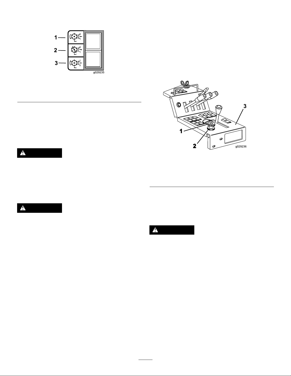
ControllingthePositionofan IndividualCuttingUnit
Thecuttingunitsmayberaisedorloweredindependently
usingthebankof3lift-controllevers.
1.Tolowerthecuttingunits,operatethelift-control
leversinadownwarddirectionandrelease(Figure26).
Note:Thecylinderdrivewillengagewhenthecutting
unitsareapproximately300mm(11.8inches)above
groundlevel.Thecuttingunitsarenowin‘oat’mode
andwillfollowthegroundcontours.
Important:Thelift-controlleversmustbelocked
inposition1whilemoving .Donotmowwiththe
liftcontrolleversinposition2.
Thedualliftcongurationcontrolfunctionenablesthelift
controlstobeusedinthefollowingways(Figure27):
Figure27
1.5-gangmode
2.3/5-gangmode5.Rightliftlever
3.Leftliftlever
4.Centerliftlever
Figure26
1.Position1—down/oat4.Leftliftlever
2.Position2—neutral
3.Position3—raise
Note:Theliftleverswillcontroldifferentcutting
unitsdependingontheliftcongurationmode;refer
toDualLiftCongurationControl(page25).
2.Toraisethecuttingunits,operatethelift-controllevers
inanupwarddirectionandholdinposition3.
Note:IfthecuttingunitdriveswitchisintheON
position,thecylinderdrivewilldisengagewhenthe
cuttingunitsareapproximately300mm(11.8inches)
abovegroundlevel.
3.Releasethelift-controlswitcheswhenthecuttingunits
areattherequiredheight.
Note:Thecontrolswitcheswillautomaticallyreturn
toposition2andthearmsarehydraulicallylockedinto
position.
5.Centerliftlever
6.Rightliftlever
5-gangmode:
•Theleftliftlevercontrolstheleftwingcuttingunit.
•Thecenterliftlevercontrolstheleftfront,center,and
rightfrontcuttingunits.
•Therightliftlevercontrolstherightwingcuttingunit.
3/5-gangmode:
•Theleftliftlevercontrolstheleftwingandleftfront
cuttingunits.
•Thecenterliftlevercontrolsthecentercuttingunit.
•Therightliftlevercontrolstherightwingandrightfront
cuttingunits.
3/5-gangmodewithleftandrightwingcuttingunits
lockedintransportposition:
•Theleftliftlevercontrolstheleftfrontcuttingunit.
•Thecenterliftlevercontrolsthecentercuttingunit.
•Therightliftlevercontrolstherightfrontcuttingunit.
25
Page 26
EngagingtheCuttingUnit Drive
Figure28
1.Forward3.Reverse
2.Off
Youcanengagethecuttingunitdriveonlywhenyouareseated
correctly,refertoUnderstandingtheOperatorPresence
Controls(page23).
Forwardrotationcuttingunitdriveengagement:Press
thetopofthecuttingunitdriveswitchtotheFORWARD
position.
Toengageweighttransfer:Youcanvarytheamountof
weighttransfertosuitoperatingconditionsbyrotatingthe
weighttransferhandwheelasfollows:
1.Releasethevalvelocknut1/2turnanti-clockwiseand
hold.
2.Rotatethevalvehandwheel.
•Anti-clockwisetoreduceweighttransfer.
•Clockwisetoincreaseweighttransfer.
3.Tightenthenut.
WARNING
Onlyoperatetheforwardcuttingunitrotation,
oncethereelshavecompletelystopped,otherwise
machinedamagecouldoccur.
Reverserotationcuttingunitdriveengagement:Press
thebottomofthecuttingunitdriveswitchtotheREVERSE
position.
WARNING
Onlyoperatethereversecuttingunitrotation,once
reelshavecompletelystopped,otherwisemachine
damagecouldoccur.
Allcuttingunitdrivesdisengagement:Settheswitchto
themiddleposition.
Tolowerthecuttingunit:Operatethelift-controllever
inadownwarddirection.Thecylinderwilldrivewhenthe
cuttingunitsareapproximately300mm(11.8inches)above
groundlevel.
Usingthe Weight-Transfer/Traction Assistance
Avariablehydraulicweighttransfersystemisprovidedfor
improvingtiregripwiththegrasssurface-tractionassistance.
Hydraulicpressureinthecuttingunitsliftsystemprovidesa
liftingforcewhichreducesthecuttingunits’weightonthe
groundandtransferstheweightasadownwardforceontothe
tiresofthemachine.Thisactionisknownasweighttransfer.
Figure29
1.Weight-transferwheel3.Controlpanel
2.Lockwheel
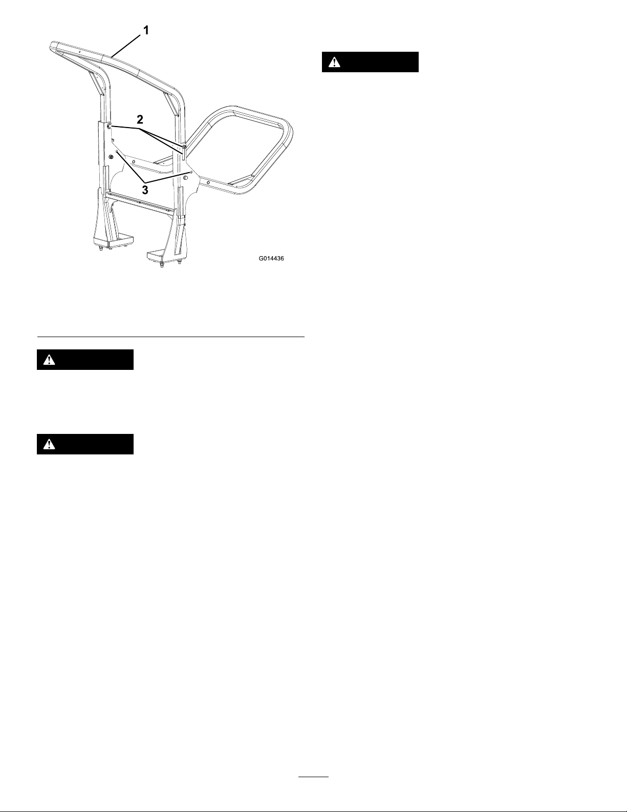
FoldingtheROPS
Theupperframemaybefoldeddowntoallowaccessinto
areasofrestrictedheight.
WARNING
Whiletheupperframeisfoldeddownitdoesnot
provideanyprotectionintheeventofaroll-overand
shouldnotbeconsideredasaRollOverProtective
Structure.
1.Applytheparkingbrakeandswitchofftheengine.
2.Supporttheweightoftheupperframewhileremoving
thehandnuts,washersandretainingboltsfromthe
pivotbrackets(Figure30).
3.Carefullylowertheframedownwarduntilitrestson
thestops.
4.Inserttheretainingboltsinthelowerholesandfully
tightenthehandnutstosupporttheupperframein
itsloweredposition.
5.Toraisetheframe,followtheseinstructionsinreverse
order.
26
Page 27
3
2
1
G014436
ClearingtheCuttingCylinders
WARNING
Neverattempttorotatethecuttingcylindersby
hand.
•Theremaybesomeresidualpressureinthe
hydraulicsystemwhichcouldcauseinjury
throughsuddenmovementofthecylinder(s)
whentheblockageisreleased.
•Alwayswearprotectiveglovesanduseasuitable
strongwoodeninstrument.
•Ensurethatthewoodeninstrumentwillt
betweenthebladesandthroughthecylinder
andislongenoughtoprovidesufcientleverage
toreleasetheblockage.
Figure30
1.Upperframe
2.Handnuts,washersand
retainingbolts
3.Lowerholes
WARNING
Whenintheraisedposition,bothretainingbolt
assembliesmustbeinstalledandfullytightenedto
ensurefullrolloverprotection.
WARNING
Becarefulloweringandraisingtheupperframeto
prevententrapmentofngersbetweenxedpart
andpivotpartofthestructure.
•Keepallnuts,boltsandscrewscorrectlytorquedensure
thattheequipmentisinsafeworkingcondition.
•Replacewornordamagedpartsforsafety.
•Ensurethattheseatbeltandmountingsareinsafe
workingorder.
•Weartheseatbeltwhentheupperframeisraisedandno
seatbeltwhentherollbarislowered.
1.Stopthemachineonlevelground.
2.Applytheparkingbrakeanddisengagealldrives.
3.Lowerthecuttingunitstothegroundorsecurelylock
inthedesignatedtransportpositions.
4.Stoptheengineandremovetheignitionkeytoisolate
allpowersourcesandcheckthattheyarestopped.
5.Releaseallstoredenergydevices.
6.Checkthatallmovingpartsarestationary.
7.Usingasuitablestrongwoodeninstrument,remove
theblockage.Makesurethatthewoodeninstrumentis
properlysupportedinthecylinderandavoidtheuseof
excessiveforcetopreventdamage.
8.Ensurethatthewoodeninstrumentisremovedfrom
thecuttingcylinderbeforerestartingthepowersource.
9.Repairoradjustthecylinderifrequired.
Important:Theupperframeisanintegralandeffective
safetydevice.Keeptheupperframeintheraised
positionwhenoperatingthemachine.Lowertheupper
frametemporarilyonlywhenabsolutelynecessary.
JackingPoints
Note:Usejackstandstosupportthemachinewhenrequired.
•Front—underthefrontarmmount.
•Rear—rearstrappinghook.
27
Page 28

OperatingTips
BecomingFamiliarwiththeMachine
Beforemowinggrass,practiceoperatingthemachineinan
openarea.Startandstoptheengine.Operateinforwardand
reverse.Lowerandraisethecuttingunitsandengageand
disengagethecuttingunits.Whenyoufeelfamiliarwiththe
machine,practiceoperatingupanddownslopesatdifferent
speeds.
UnderstandingtheWarningSystem
Ifawarninglightcomesonduringoperation,stopthe
machineimmediatelyandcorrecttheproblembefore
continuingoperation.Seriousdamagecouldoccurifyou
operatethemachinewithamalfunction.
MowingGrass
Therotationalspeedofthecuttingcylindersshouldalways
bekeptashighaspossibleinordertomaintainthehighest
qualityofcut.Thisinturnrequiresthattheenginespeed
bekeptashighaspossible.
WARNING
Takecarewhentravelingoverobstaclessuchas
roadsidecurbs.Alwaystravelatslowspeedover
obstaclestopreventdamagetothetires,wheels,
andsteeringsystem.Ensurethatthetiresare
inatedtotherecommendedpressures.
OperatingtheMachineonSlopes
Useextracarewhenoperatingthemachineonslopes.Drive
slowlyandavoidsharpturnsonslopestopreventrollovers.
Lowerthecuttingunitsforsteeringcontrolwhengoing
downhill.
UsingtheRearRollerScrapers
Itisgenerallywisetoremoverearrollerscraperswhere
conditionsallow ,asoptimumgrassdischargeisachieved
withoutthem.Installthescraperswhenconditionsaresuch
thatmudandgrassstarttobuildupontherollers.When
installingthescraperwires,ensurethattheyarecorrectly
tensioned.
Cuttingperformanceisbestwhencuttingagainstthelieof
thegrass.Inordertotakeadvantageofthisfact,theoperator
shouldattempttoalternatethedirectionofmowingbetween
cuts.
Takecarenottoleaveuncutstripsofgrassattheoverlap
pointsbetweenadjacentcuttingunitsbyavoidingtightturns.
MaximizingtheQualityofCut
Thequalityofcutwilldeteriorateiftheforwardspeedis
excessive.Alwaysbalancethequalityofcutwiththeworkrate
requiredandsettheforwardspeedaccordingly.
MaximizingEngineEfciency
Donotlettheenginelabor.Ifyounoticethattheengine
startstolabor,reducetheforwardspeedorincreasethe
heightofcut.Checkthatthecuttingcylindersarenotin
heavycontactwiththeirbottomblades.
DrivingtheMachineinTransportMode
Alwaysdisengagethecuttingunitdrivewhentravelingacross
un-grassedareas.Grasswilllubricatethecuttingedgeswhilst
mowing.Excessiveheatwillbuildupifthecuttingcylinders
arerunwhennotmowingandthiswillcauserapidwearto
takeplace.Forthisreasonitisalsowisetoreducecutting
speedwhenmowinglightlygrassedareasorwhenthegrassis
dry.Becarefulwhendrivingbetweenobjectssothatyoudo
notaccidentallydamagethemachineorthecuttingunits.
28
Page 29

Maintenance
Note:Determinetheleftandrightsidesofthemachinefromthenormaloperatingposition.
RecommendedMaintenanceSchedule(s)
MaintenanceService
Interval
Aftertherst50hours
Beforeeachuseordaily
Every50hours
MaintenanceProcedure
•Changetheengineoilandlter.
•Changethetransmission-oillter.
•Changethehydraulicreturnlter.
•Checktheenginespeed(idleandfullthrottle).
•Checkthetirepressure.
•Greasethebearings,bushings,andpivots(greasethemimmediatelyafterevery
washingregardlessoftheintervallisted).
•Checktheair-lter-blockageindicator.
•Checktheengine-oillevel.
•Checkthetirepressure.
•Torquethewheellugnuts.
•Checkthelevelofthecoolantinthecoolingsystem.
•Removedebrisfromthescreen,oilcoolers,andradiator(morefrequentlyindirty
operatingconditions).
•Checkthesafetyinterlocksystem.
•Checkthehydraulicuidlevel.
•Checkthehydrauliclinesandhosesforleaks,kinkedlines,loosemountingsupports,
wear,loosettings,weatherdeterioration,andchemicaldeterioration.
•Checkthefastenersofthemachine.
•Checkthecuttingunits.
•Checktheforward/reversetravelpedalaction.
•Greasethebearings,bushings,andpivots(greasethemimmediatelyafterevery
washingregardlessoftheintervallisted).
•Checktheconditionofandcleanthebattery.
•Checkthebatterycableconnections.
Every100hours
Every150hours
Every200hours
Every400hours
Every500hours
Every800hours
Beforestorage
Every2years
•Inspectthecoolingsystemhoses.
•Checktheconditionandtensionofthealternatorbelt.
•Changetheengineoilandlter.
•Servicetheaircleaner.(Morefrequentlyinextremelydirtyordustyconditions)
•Checkthefuellinesandconnections.
•Replacethefuelltercanister.
•Checktheenginespeed(idleandfullthrottle).
•Checkengineoverheatwarningsystem.
•Changethetransmission-oillter.
•Checktherearwheelalignment.
•ServicetheHydraulicSystem
•Changethehydraulicreturnlter.
•Checkhydraulicoiloverheatwarningsystem
•Drainandcleanthefueltank.
•Flushandreplacethecoolingsystemuid.
•Adjusttheenginevalves(refertotheengineoperator’smanual).
•Drainandcleanthefueltank.
•Replaceallmovinghoses.
•Replacethetransmissioncable.
29
Page 30

DailyMaintenanceChecklist
Duplicatethispageforroutineuse.
Fortheweekof:
MaintenanceCheckItem
Checkthesafetyinterlockoperation.
Checkthebrakeoperation.
Checktheengineoilandfuellevel.
Checktheairlterrestrictionindicator.
Checktheradiatorandscreenfordebris.
Checkunusualenginenoises.
Checkunusualoperatingnoises.
Checkthehydraulicsystemoillevel.
Checkhydraulichosesfordamage.
Checkforuidleaks.
Checkthetirepressure.
Checktheinstrumentoperation.
Checkallgreasettingsforlubrication.
Touch-updamagedpaint.
1.Checktheglowplugandinjectornozzlesifhardstarting,excesssmoke,orroughrunningisnoted.
1
2
Mon.Tues.Wed.Thurs.Fri.
Sat.Sun.
2.Immediatelyaftereverywashing,regardlessoftheintervallisted
NotationforAreasofConcern
Inspectionperformedby:
ItemDate
1
2
3
4
5
6
7
8
Important:Refertoyourengineoperator’smanualforadditionalmaintenanceprocedures.
Information
30
Page 31

Pre-Maintenance
Beforeperforminganymaintenanceensurethattheengineisswitchedtooffandtheignitionkeyisremoved,theparking
brakeisset,thereisnopressureinthehydraulicsystem,thecuttingunitsareonthegroundandthesafetyprecautionsin
thismanualhavebeenreadandunderstood.
CAUTION
Ifyouleavethekeyintheignitionswitch,someonecouldaccidentlystarttheengineandseriouslyinjure
youorotherbystanders.
Removethekeyfromtheignitionbeforeyoudoanymaintenance.
Important:Regularmaintenanceisessentialforthecontinuedsafeoperationofthemachine.Correctservicingwill
prolongtheworkinglifeofthemachineandsafeguardtheWarranty.AlwaysusegenuineT oroservicepartsasthese
wareaccuratelymatchedtotherequiredduty.Theuseofnon-genuinepartsmayresultinpersonalinjuryordeath.
Dirtandcontaminationaretheenemiesofanyhydraulicsystem.Whencarryingoutmaintenanceproceduresonthehydraulic
systemalwaysensurethattheworkareaandthecomponentsarethoroughlycleanbefore,duringandafterretting.Ensurethat
allopenhydrauliclinesandports,etc.arepluggedduringmaintenanceprocedures.
Therecommendedserviceintervalsarebasedonnormaloperatingconditions.Severeorunusualconditionswillnecessitate
shorterserviceintervals.
Alwaysgreasethepivotpointsimmediatelyafterpressurewashingorsteamcleaning.
WARNING
Theengine,transmissionoilandhydraulicsystemswillbehotaftermachineuse.Allowthesystemstocool
beforeworkingonthemachine,particularlybeforeworkingontheengineorwhenchangingoiloroillters.
31
Page 32

ServiceIntervalChart
Figure31
32
Page 33

Lubrication
bearingsandbushingsimmediatelyaftereverywashing,
regardlessoftheintervallisted.
GreasingtheBearings, Bushings,andPivots
ServiceInterval:Beforeeachuseordaily
Every50hours
Lubricateallgreasettingsforthebearingsandbushings
withNo.2general-purpose,lithium-basedgrease.Lubricate
Replaceanydamagedgreasettings.
Greaseallcuttingunitgreasepointsandinjectsufcient
greasesuchthatyoucanseecleangreaseescapingfromthe
rollerendcaps.Thisprovidesvisibleevidencethattheroller
sealshavebeenpurgedofgrassanddebrisandwillensures
maximumworkinglife.
Thegrease-ttinglocationsandquantitiesareasfollows:
Figure32
1.–Greasedaily3.–Greaseevery50hours(weekly)
2.
–Greasedaily(iftted)
33
Page 34

EngineMaintenance
1
G014437
CheckingtheEngineOverheat WarningSystem
ServiceInterval:Every500hours
Figure33
1.Temperatureswitch
1.TurntheignitionkeytotheignitiononpositionI.
2.Disconnecttheblack/purplewireterminalfromthe
enginetemperatureswitch.
3.Touchthemetalterminalofthiswireontoasuitable
earthpoint,ensuringthatthemetalsurfacesmake
goodcontact.
Thehornwillsoundandtheenginecoolanttemperature
warninglightwillilluminatetoconrmcorrectoperation.
Ifthesystemisfaulty ,makerepairsbeforeoperatingthe
machine.
ServicingtheAirCleaner
Figure34
1.Aircleanerbody3.Rubberoutletvalve
2.Aircleanercover
3.Removethecoverfromtheaircleanerbody.Before
removingthelter,uselowpressureair(40psi,clean
anddry)tohelpremovelargeaccumulationsofdebris
packedbetweentheoutsideofthelterandthe
canister.Avoidusinghighpressureairwhichcould
forcedirtthroughthelterintotheintaketract.
Thiscleaningprocesspreventsdebrisfrommigrating
intotheintakewhentheprimarylterisremoved.
4.Removeandreplacetheprimarylter.
Cleaningoftheusedelementisnotrecommendeddue
tothepossibilityofdamagetotheltermedia.Inspect
thenewlterforshippingdamage,checkingthesealing
endofthelterandthebody .Donotuseadamaged
element.Insertthenewlterbyapplyingpressureto
theouterrimoftheelementtoseatitinthecanister.
Donotapplypressuretotheexiblecenterofthe
lter.
5.Cleanthedirtejectionportlocatedintheremovable
cover.Removetherubberoutletvalvefromthecover,
cleanthecavityandreplacetheoutletvalve.
6.Installthecoverorientingtherubberoutletvalveina
downwardposition—betweenapproximately5o’clock
to7o’clockwhenviewedfromtheend.
ServiceInterval:Every200hours(Morefrequentlyin
extremelydirtyordustyconditions)
Beforeeachuseordaily
Checktheaircleanerbodyfordamagewhichcouldcausean
airleak.Replaceifdamaged.Checkthewholeintakesystem
forleaks,damageorloosehoseclamps.
CheckingtheEngine-OilLevel
ServiceInterval:Beforeeachuseordaily
Crankcasecapacityisapproximately7.6L(8qt)withthelter.
Usehigh-qualityengineoilthatmeetsthefollowing
specications:
•APIClassicationLevelRequired:CH-4,CI-4orhigher
Changingtheairlterbeforeitisnecessaryonlyincreasesthe
chanceofdirtenteringtheenginewhenthelterisremoved.
•Preferredoil:SAE15W-40(above32°C(0°F))
•Alternateoil:SAE10W-30or5W-30(alltemperatures)
Important:Besurethecoverisseatedcorrectlyand
sealswiththeaircleanerbody .
1.Opentheenginecover.
2.Releasethelatchessecuringtheaircleanercovertothe
aircleanerbody(Figure34).
ToroPremiumEngineoilisavailablefromyourdistributorin
either15W -40or10W-30viscosity .
1.Parkthemachineonalevelsurface,stoptheengine,
settheparkingbrake,andremovethekeyfromthe
ignitionswitch.
2.Releasetheenginecoverlatchandopenthehood.
34
Page 35

3.Removethedipstick,wipeitclean,andinstallit(Figure
G012280
1
G012281
1
G012305
1
G012306
1
35).
Figure35
1.Dipstick
4.Removedipstickandcheckoillevelondipstick.
TheoillevelshouldbeuptotheFULLmark.
ChangingtheEngineOiland Filter
ServiceInterval:Aftertherst50hours
Every150hours
1.Removethedrainplug(Figure37)andlettheoilow
intoadrainpan.
5.IftheoillevelisbelowtheFULLmark,removethell
cap(Figure36)andaddoiluntillevelreachestheFULL
markondipstick.
Important:Donotoverll.
Figure36
1.Oilllcap
Important:Besuretokeeptheengineoillevel
betweentheupperandlowerlimitsontheoil
gauge.Enginefailuremayoccurasaresultofover
llingorunderllingtheengineoil.
6.Installtheoilllcap.
7.Closeenginecoverandsecurewiththelatches.
Figure37
1.Oildrainplug
2.Whentheoilstops,installthedrainplug.
3.Removetheoillter(Figure38).
Figure38
1.Oillter
4.Applyalightcoatofcleanoiltothenewlterseal.
5.Installthereplacementoilltertothelteradapter.
Turntheoillterclockwiseuntiltherubbergasket
contactsthelteradapter,thentightenthelteran
additional1/2turn.
Important:Donotovertightenthelter.
6.Addoiltothecrankcase;refertoCheckingthe
Engine-OilLevel(page34).
35
Page 36

FuelSystem
BleedingtheFuelSystem
Maintenance
DANGER
Undercertainconditions,dieselfuelandfuel
vaporsarehighlyammableandexplosive.Are
orexplosionfromfuelcanburnyouandothersand
cancausepropertydamage.
•Useafunnelandllthefueltankoutdoors,in
anopenarea,whentheengineisoffandiscold.
Wipeupanyfuelthatspills.
•Donotllthefueltankcompletelyfull.Add
fueltothefueltankuntilthelevelis6to13mm
(1/4to1/2inches)belowthebottomoftheller
neck.Thisemptyspaceinthetankallowsthe
fueltoexpand.
•Neversmokewhenhandlingfuel,andstayaway
fromanopenameorwherefuelfumesmaybe
ignitedbyaspark.
•Storefuelinaclean,safety-approvedcontainer
andkeepthecapinplace.
Youmustbleedthefuelsystembeforestartingtheengine
afteranyofthefollowingsituations:
•Initialstartupofanewmachine
•Enginehasceasedrunningduetolackoffuel
•Maintenancehasbeenperformeduponfuelsystem
components(i.e.,replacedlter,servicedseparator,etc.)
DANGER
Undercertainconditions,dieselfuelandfuel
vaporsarehighlyammableandexplosive.Are
orexplosionfromfuelcanburnyouandothersand
cancausepropertydamage.
•Useafunnelandllthefueltankoutdoors,in
anopenarea,whentheengineisoffandiscold.
Wipeupanyfuelthatspills.
•Donotllthefueltankcompletelyfull.Add
fueltothefueltankuntilthelevelis6to13mm
(1/4to1/2inches)belowthebottomoftheller
neck.Thisemptyspaceinthetankallowsthe
fueltoexpand.
DrainingtheFuelTank
ServiceInterval:Every800hours
Beforestorage
Drainandcleanthefueltankifthefuelsystembecomes
contaminatedorifthemachineistobestoredforanextended
period.Usecleanfueltoushoutthetank.
CheckingtheFuelLinesand Connections
ServiceInterval:Every400hours/Yearly(whichevercomes
rst)
Checkthefuellinesandconnections.Inspectthemfor
deterioration,damage,orlooseconnections.
ReplacingtheFuelFilter Canister
ServiceInterval:Every400hours
1.Cleantheareawheretheltercanistermounts.
2.Removetheltercanisterandcleanthemounting
surface.
3.Lubricatethegasketontheltercanisterwithcleanoil.
4.Installthenewltercanisterbyhanduntilthegasket
contactsmountingsurface,thenrotateitanadditional
1/2turn.
•Neversmokewhenhandlingfuel,andstayaway
fromanopenameorwherefuelfumesmaybe
ignitedbyaspark.
•Storefuelinaclean,safety-approvedcontainer
andkeepthecapinplace.
1.Parkthemachineonalevelsurfaceandensurethatthe
fueltankisatleasthalffull.
2.Openthehood.
3.TurnthekeyintheignitionswitchtotheONposition
andcranktheengine.
Note:Themechanicalpumpwillsuckfueloutofthe
tank,llthefuellterandfuelhoseandforcetheair
intotheengine.Thiscouldtakesometimetofully
purgealltheairoutofthesystemandtheenginemight
reerraticallyuntilallairispurgedout.Whenallairis
purgedandtheengineisrunningsmoothly ,itshouldbe
runforafewminutestoensurethatitisfullypurged.
36
Page 37

BleedingAirfromtheFuel
G012307
1
Injectors
Note:Onlyusethisprocedureifthefuelsystemhasbeen
purgedofairthroughnormalprimingproceduresandthe
enginewillnotstart;refertoBleedingtheFuelSystem(page
36).
1.LoosenthepipeconnectiontotheNo.1nozzleand
holderassembly(Figure39).
Figure39
1.Fuelinjectors
ElectricalSystem
Maintenance
Important:Beforeweldingonthemachine,disconnect
bothcablesfromthebatteryandtheterminalconnector
fromthealternatortopreventdamagetotheelectrical
system.
ServicingtheBattery
WARNING
CALIFORNIA
Proposition65Warning
Batteryposts,terminals,andrelated
accessoriescontainleadandleadcompounds,
chemicalsknowntotheStateofCalifornia
tocausecancerandreproductiveharm.
Washhandsafterhandling.
2.MovethrottletotheFASTposition.
3.TurnthekeyinthekeyswitchtotheSTARTposition
andwatchthefuelowaroundtheconnector.
Note:Theenginewillcrank.
4.Whenyouobserveasolidowoffuel,turnthekey
totheOFFposition.
5.Tightenthepipeconnectorsecurely.
6.Repeatsteps1through5ontheremainingnozzles.
DANGER
Batteryelectrolytecontainssulfuricacidwhichisa
deadlypoisonandcausessevereburns.
•Donotdrinkelectrolyteandavoidcontactwith
skin,eyes,orclothing.Wearsafetyglassesto
shieldyoureyesandrubberglovestoprotect
yourhands.
•Fillthebatterywherecleanwaterisalways
availableforushingtheskin.
WARNING
Chargingthebatteryproducesgassesthatcan
explode.
Neversmokenearthebatteryandkeepsparksand
amesawayfromit.
WARNING
Batteryterminalsormetaltoolscouldshortagainst
metaltractorcomponentscausingsparks.Sparks
cancausethebatterygassestoexplode,resulting
inpersonalinjury.
•Whenremovingorinstallingthebattery,donot
allowthebatteryterminalstotouchanymetal
partsofthemachine.
•Donotallowmetaltoolstoshortbetween
thebatteryterminalsandmetalpartsofthe
machine.
37
Page 38

WARNING
Incorrectbatterycableroutingcoulddamagethe
machineandcablescausingsparks.Sparkscan
causethebatterygassestoexplode,resultingin
personalinjury.
•Always
cablebeforedisconnectingthepositive(red)
cable.
•Always
beforeconnectingthenegative(black)cable.
Checkthebatteryconditionweeklyorafterevery50hours
ofoperation.Keeptheterminalsandtheentirebatterycase
cleanbecauseadirtybatterywilldischargeslowly .Toclean
thebattery,washtheentirecasewithasolutionofbaking
sodaandwater.Rinseitwithclearwater.Coatthebattery
postsandcableconnectorswithGrafo112X(skin-over)
grease(ToroPartNo.505-47)orpetroleumjellytoprevent
corrosion.
disconnect
connect
thenegative(black)battery
thepositive(red)batterycable
DriveSystem
Maintenance
Changingthe Transmission-OilFilter
ServiceInterval:Aftertherst50hours
Every500hours
1.Unscrewandremovethebottomofthetransmission-oil
lterhousing.
2.Withdrawthelterelementanddiscardit.
3.Retanewlterelement.
4.Installthehousing.
Figure40
1.Transmission-oillter
2.Centercuttingunit
3.Hydraulic-oiltank
CheckingtheRearWheel Alignment
ServiceInterval:Every500hours
Topreventexcessivetirewearandensuresafemachine
operation,therearwheelsmustbecorrectlyalignedto3to
8mm(0.12to0.31inches).
1.Settherearwheelsinthestraightaheadposition.
2.Measureandcomparethedistancebetweenthefront
sidewallsandtherearsidewallsatthewheelcenter
height(Figure41).
Note:Thedistancebetweenthefrontsidewallsmust
beset3to8mm(0.12to0.31inches)lessthanthe
distancebetweentherearsidewalls.
38
Page 39

2
4
1
G014442
3
x + 3 - 8mm
x
Figure41
1.Wheelcenterheight
2.Tire4.Track-rodassembly
3.Directionofforwardtravel
CoolingSystem
Maintenance
Capacityofthecoolingsystemis14L(3.7USgallons).
Alwaysprotectthecoolingsystemwitha50/50solutionof
waterandethyleneglycolanti-freeze.Donotusewateronly
inthecoolingsystem.
•Afterevery100operatinghours,tightenhoseconnections.
Replaceanydeterioratedhoses.
•Afterevery800operatinghours,drainandushthe
coolingsystem.Addanti-freeze.
3.Toadjustthealignmentoftherearwheels,backoffthe
leftandrightlocknutsonthetrackrodassembly.
Note:Theleftlocknutisaleftthread.
4.Rotatethetrackrodtoachievethecorrectdistanceas
describedaboveandtightenthelocknutssecurely.
CheckingtheTirePressure
ServiceInterval:Beforeeachuseordaily
Checktheairpressureinthefrontandreartires.Refertothe
chartbelowforthecorrectpressure.
Important:Maintaincorrecttirepressureinalltiresto
ensurecorrectcontactwiththeturf.
TiresTireTypeRecommendedTirePressures
FrontAxle26x12-
12,4ply
RearAxle20x10-
8,4ply
Conditions
0.7bar(10
0.7bar(10
Turf
psi)
psi)
Road
Conditions
1.4bar(20
psi)
1.4bar(20
psi)
Maximum
Pressure
1.7bar(25
psi)
1.7bar(25
psi)
CheckingtheCoolingSystem
ServiceInterval:Beforeeachuseordaily
Capacityofsystemis14L(3.7USgallons).
1.Carefullyremovetheradiatorcapandexpansiontank
cap(Figure42).
CAUTION
Iftheenginehasbeenrunning,the
pressurized,hotcoolantcanescapeandcause
burns.
•Donotopentheradiatorcapwhenthe
engineisrunning.
•Usearagwhenopeningtheradiatorcap,
andopenthecapslowlytoallowsteamto
escape.
2.Checklevelofcoolantinradiatorwhenthecoolantis
cold.Radiatorshouldbelledtothetopoftheller
neckandtheexpansiontanklledbetweenthemarks
onitsside(Figure42).
CheckingtheTorqueofthe WheelNuts
ServiceInterval:Beforeeachuseordaily
Torquethewheelnutsto200N-m(148ft-lb)forthefront
axle,and54N-m(40ft-lb)fortherearaxle.
WARNING
Failuretomaintainpropertorqueofthewheelnuts
couldresultinpersonalinjury.
Ensurethatthewheelnutsaretorquedproperly.
1.Fullline
2.Lowline
39
Figure42
Expansiontank
Page 40

3.Ifthecoolantlevelislow,adda50/50mixtureofwater
andethyleneglycolanti–freeze.Donotoverll.
BrakeMaintenance
Important:Donotusewateronlyor
alcohol/methanolbasecoolants.
4.Installtheradiatorandexpansiontankcaps.
RemovingDebrisfromthe CoolingSystem
ServiceInterval:Beforeeachuseordaily—Removedebris
fromthescreen,oilcoolers,andradiator
(morefrequentlyindirtyoperating
conditions).
1.Turntheengineoffandremovethekeyfromthe
ignitionswitch.
2.Releasethefrontenginecoverlatchesandraisethe
enginecover.
3.Thoroughlycleanalldebrisoutoftheenginearea.
4.Cleanbothsidesoftheoilcooler,radiatorandrear
engineareathoroughlywithcompressedair.
5.Lowertheenginecoverandsecurethelatches.
TowingtheMachine
1.Applytheparkingbrakeofthetowingmachine.
2.Chockthefrontwheelsofthemachinetopreventit
fromrollingaway.
3.Connectarigidtowbarbetweenthetowingeyeonthe
machineandasuitabletowingvehicle.
Note:Ensurethatthetowingvehiclespecicationis
suitedtobrakingthecombinedweighttorestwhile
maintainingcompletecontrolatalltimes.
4.Removethehexplugfromtheright,frontwheelmotor
discbrakeassembly(Figure43).
Figure43
1.Frontwheelmotor
2.Hexplug
3.Brake-releasebar
5.Insertasetscrew(M12x40mm)andwasher(M12)
throughthebrake-releasebarandintotheholeinthe
centerofthemotorendplate(Figure43).
6.Tightenthesetscrewintothethreadedholeinthe
brakepistonuntilthebrakeisreleased.
7.Repeatthesteps4through6fortheleft,frontwheel
motordiscbrakeassembly .
8.Todecommissionthehydraulicservicebrakingsystem,
openthetransmissionbypassvalveontopofthe
transmissionpumpasshowninFigure44.
40
4.Washer(M12)
5.Setscrew(M12x40mm)
Page 41

Important:Thevalveisfullyopenat3
counter-clockwiserevolutions.Donotopenthe
valvepast3revolutions
Note:Thesteeringmustbeoperatedmanuallywhen
themachineisbeingtowed.Thesteeringwillfeel
heavyasthereisnohydraulicassistancewhenthe
engineisoff.
WARNING
Beforeusingthemachine,ensurethatthebraking
systemoperatescorrectly.Carryoutinitialchecks
withthemachineatslowspeed.
Donotoperatethemachineifthebraking
systemdoesnotworkcorrectlyorwiththebrakes
decommissioned.
Figure44
9.Removethewheelchocksbeforetowing.
Note:Themachineisnowinafreewheelcondition
andcanbetowedforashortdistanceataslowspeed.
RecommissioningtheMachine afterTowing
1.Chockthefrontwheels.
2.Closethetransmissionbypassvalve(Figure44).
Note:Turnthevalveclockwiseandtorque48N-m
(30ft-lb)to52N-m(50ft-lb).
3.Removethesetscrew,washer,andbrake-releasebar
fromtherightandleftfrontwheelmotordiscbrake
assemblies(Figure43).
4.Installthehexplugintothemotorendplateofthe
motordiscassemblies.
5.Storethebrakereleasebars,washers,andsetscrews
forfutureuse.
6.Removethewheelchocks.
7.Disconnectthetowbar.
Note:Thebrakingsystemwillnowoperatenormally.
41
Page 42
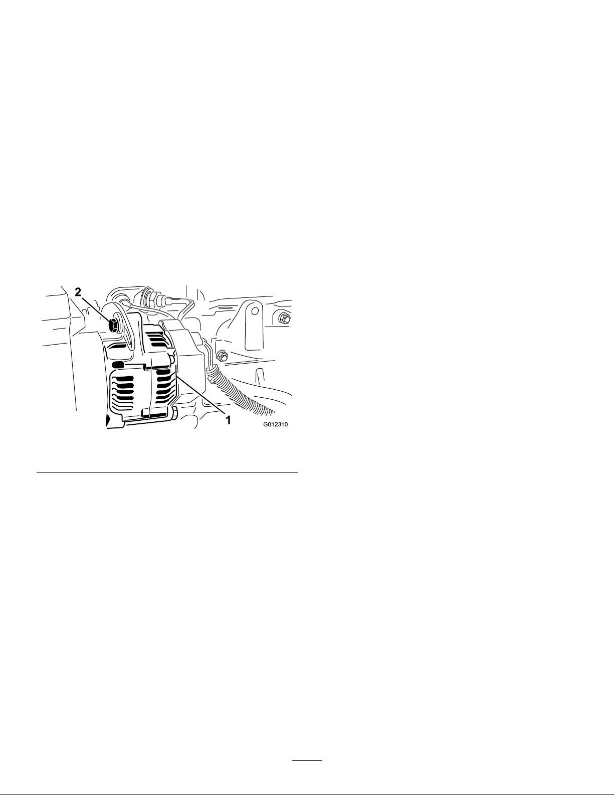
BeltMaintenance
G012310
1
2
ControlsSystem
Checktheconditionandtensionofthealternatorbeltafter
therstdayofoperationandevery100operatinghours
thereafter.
CheckingtheConditionand TensionoftheAlternatorBelt
ServiceInterval:Every100hours
•Propertensionwillallowa10mm(3/8inch)deection
whenaforceof4.5kg(10lb)isappliedonthebelt
midwaybetweenthepulleys.
•Ifthedeectionisnot10mm(3/8inch),loosenthe
alternatormountingbolts(Figure45).Increaseor
decreasethealternatorbelttensionandtightenthebolts.
Note:Checkdeectionofbeltagaintoensurethatthe
tensioniscorrect.
Maintenance
CheckingtheForward/Reverse TravelPedalAction
Withtheengineswitchedoff,operatetheforwardandreverse
travelpedalsthroughthefullrangeofarticulationandensure
thatthemechanismreturnsfreelytotheNEUTRALposition.
Checkingthe Operator-PresenceSeat Switch
ServiceInterval:Beforeeachuseordaily
1.Sitontheoperatorseatandstarttheengine.
2.Lowerthecuttingunitstotheground.
3.Engagethecutterdriveintheforwarddirection.
4.Risefromtheoperatorseatandcheckthatthecutting
cylinderscometoastopafteraninitial1to2second
delay.
5.Repeattheprocedurewiththecuttingcylinders
runninginreverse.
Figure45
1.Alternator2.Mountingbolt
CheckingtheCutterDrive InterlockSwitch
1.Stoptheengine.
2.OperatethecutterdriveswitchtotheOFFposition
andturntheignitionkeytopositionI.Thecuttingunit
driveswitchindicatorlightshouldnotilluminate.
3.Operatetheswitchtotheforwardposition.
Note:Theindicatorlightshouldnotilluminateand
theengineshouldnotstartwhentheignitionkeyis
turned.Repeatforthereverseposition.
CheckingtheParkingBrake InterlockSwitch
1.Stoptheengine.
2.Engagetheparkingbrake.
3.TurntheignitionkeytopositionI.Theparkingbrake
indicatorlightshouldilluminate.
4.Disengagetheparkingbrake.Theindicatorlight
shouldgooutandtheengineshouldnotstartwhen
theignitionkeyisturned.
5.Settheparkingbrake,sitontheoperatorseat,andstart
theengine.
6.Releasetheparkingbrake.
42
Page 43

7.Risefromtheoperatorseatandcheckthattheengine
stops.
CheckingtheTransmission NeutralInterlockSwitch
1.Stoptheengine.
2.Removeyourfootfromtheforward/reversetravel
pedals.
3.TurntheignitionkeytopositionIandthetransmission
neutralindicatorlightshouldilluminate.
4.Applylightpressuretothetravelpedalsinaforward
andreversedirectiontocheckthattheindicatorlight
turnsoff.
Note:Takeextremecaretoensurethattheareaaroundthe
machineisclearbeforecheckingthattheenginedoesnot
startunderthiscondition.
CheckingtheDiverterValves
1.Sitontheoperatorseatandstarttheengine.
2.Engagethecutting-unitdriveswitchintheforward
direction.
3.Lowerthecuttingunitstotheground.
Note:Thecylinderdrivewillengagewhenthecutting
unitsareapproximately300mm(12inches)above
groundlevel.
4.Raisethecuttingunits.
HydraulicSystem
Maintenance
WARNING
Hydraulicuidescapingunderpressurecan
penetrateskinandcauseinjury.
•Makesureallhydraulicuidhosesandlinesare
ingoodconditionandallhydraulicconnections
andttingsaretightbeforeapplyingpressureto
thehydraulicsystem.
•Keepyourbodyandhandsawayfrompin
holeleaksornozzlesthatejecthighpressure
hydraulicuid.
•Usecardboardorpapertondhydraulicleaks.
•Safelyrelieveallpressureinthehydraulicsystem
beforeperforminganyworkonthehydraulic
system.
•Getimmediatemedicalhelpifuidisinjected
intoskin.
ServicingtheHydraulic System
ServiceInterval:Every500hours
Note:Keepwaterawayfromelectricalcomponents.Usea
dryclothorbrushtocleansuchareas.
Note:Thecylinderdrivewilldisengagewhenthe
cuttingunitsareapproximately300mm(12inches)
abovegroundlevel.
Ifthedivertervalvesarenotoperatingcorrectly,contactyour
AuthorizedServiceDealer.
Thisprocedureisbestcarriedoutwhenthehydraulicoilis
warm(nothot).Lowerthecuttingunitstothegroundand
drainthehydraulicsystem.
1.Removetheoiltankllerangetogainaccesstothe
suctionstrainer.
2.Unscrewandremovethestrainerandcleanwith
parafnorpetrolbeforeinstalling.
3.Installthereturnlineoillterelement.
4.Installthetransmissionoillterelement.
5.Fillthehydraulictankwithfreshcleanhydraulicoilof
therecommendedgrade.
6.Runthemachineandoperateallhydraulicsystemsuntil
thehydraulicoiliswarm.
7.Checktheoillevelandtopupasnecessarytotheupper
markonthesightlevelgauge.
43
Page 44

1.Suctionstrainer
2
1
G014570
3
2.Oiltanksuctionange
Figure46
3.Fillerstrainer
4.Drainplug
Important:Manyhydraulicuidsarealmostcolorless,
makingitdifculttospotleaks.Areddyeadditivefor
thehydraulicsystemoilisavailablein20ml(2/3oz)
bottles.Onebottleissufcientfor15to22liters(4to6
USgallons)ofhydraulicoil.Orderpart44–2500from
yourAuthorizedT oroDistributor.
Synthetic,BiodegradableHydraulicFluid(Availablein
19liter(5USgallon)containersor208liter(55USgallon)
drums—seethepartscatalogorT orodistributorforpart
numbers.)
Thishigh-quality,synthetic,biodegradableuidhasbeen
testedandfoundcompatibleforthismodel.Otherbrands
ofsyntheticuidmayhaveseal-compatabilityproblems
andTorocannotassumeresponsibilityforunauthorized
substitutions.
Note:Thissyntheticuidisnotcompatiblewiththe
ToroBiodegradableFluidpreviouslysold.SeeyourToro
distributorformoreinformation.
Alternativeuids:
•MobilEALEnvirosynH46(US)
•MobilEALHydraulicOil46(International)
CheckingtheHydraulicFluid
Themachinesreservoirislledatthefactorywith
approximately77L(20.3USgallons)ofhighqualityhydraulic
uid.Checkthelevelofthehydraulicuidbeforerst
startingtheengineanddailythereafter.Therecommended
replacementuidisasfollows:
ToroPremiumAllSeasonHydraulicFluid(Availablein5
gallonpailsor55gallondrums.SeepartscatalogorToro
distributorforpartnumbers.)
Alternateuids:IftheTorouidisnotavailable,otheruids
maybeusedprovidedtheymeetallthefollowingmaterial
propertiesandindustryspecications.
Note:Torowillnotassumeresponsibilityfordamage
causedbyimpropersubstitutions,souseonlyproducts
fromreputablemanufacturerswhowillstandbehindtheir
recommendation.
HighViscosityIndex/LowPourPointAnti-wearHydraulic
Fluid,ISOVG46
MaterialProperties:
Viscosity,ASTMD445cSt@40°C44to48
ViscosityIndexASTM
D2270
PourPoint,ASTMD97-34°Fto-49°F
IndustrySpecications:
VickersI-286-S(QualityLevel),VickersM-2950-S
(QualityLevel),DenisonHF-0
cSt@100°C7.9to8.5
140to160
1.Positionmachineonalevelsurface,lowerthecutting
unitsandstoptheengine.
2.Checkthesightlevelgaugeonthesideofthetank.The
levelneedstobeattheuppermark.
3.Ifhydraulicoilisneeded,cleanareaaroundthecapof
hydraulictank(Figure47).Removecapfromthetank.
Figure47
1.Hydraulic-tankcap
2.Oiltank
3.Sight-levelgauge
4.Removethecapandllthetanktotheuppermarkon
thesightlevelgauge.Donotoverll.
Theproperhydraulicuidsmustbespeciedfor
mobilemachinery(asopposedtoindustrialplantusage),
multiweight-type,withZnDTPorZDDPantiwearadditive
package(notanashless-typeuid).
5.Installthecapontothetank.
44
Page 45
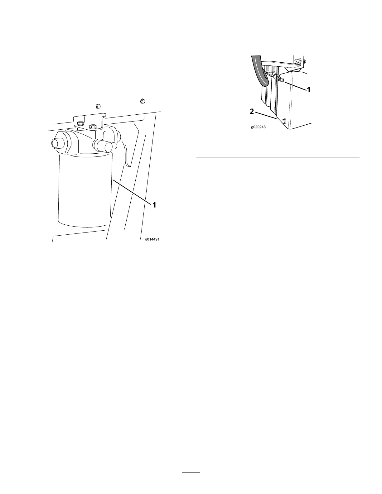
ChangingtheHydraulicOil
g014491
1
CheckingtheHydraulicOil
ReturnFilter
ServiceInterval:Aftertherst50hours
Every500hours
1.Removethereturnlter.
2.Wipeoilontothenewreturnltergasket.
3.Installthenewreturnltertothemachine.
OverheatWarningSystem
ServiceInterval:Every500hours
Figure49
1.Temperatureswitch2.Hydraulicoiltank
1.TurntheignitionkeytotheignitiononpositionI.
2.Disconnectthered/bluewireterminalfromthe
hydraulictanktemperatureswitch.
3.Touchthemetalterminalofthewireontoasuitable
earthpoint,ensuringthatthemetalsurfacesmake
goodcontact.
Figure48
1.Enginefuellter2.Hydraulicoilreturnlter
Note:Thehornwillsoundandthehydraulicoiltemperature
warninglightwillilluminatetoconrmcorrectoperation.If
necessary,makerepairsbeforeoperatingthemachine.
CheckingtheHydraulicLines andHoses
Daily,checkhydrauliclinesandhosesforleaks,kinked
lines,loosemountingsupports,wear,loosettings,weather
deterioration,andchemicaldeterioration.Makeallnecessary
repairsbeforeoperatingthemachine.
45
Page 46

CuttingUnitMaintenance
RefertoyourcuttingunitsOperator’ sManualformaintenance
procedures.
Storage
PreparingtheTractionUnitfor Storage
1.Thoroughlycleanthetractionunit,cuttingunits,and
engine.
2.Checkthetirepressure.RefertoCheckingtheTire
Pressure(page39).
3.Checkallfastenersforloosenessandtightenthemas
necessary.
4.Greaseallgreasettingsandpivotpoints.Wipeup
anyexcesslubricant.
5.Lightlysandandusetouch-uppaintonpaintedareas
thatarescratched,chipped,orrusted.Repairanydents
inthemetalbody.
6.Servicethebatteryandcablesasfollows:
A.Removethebatteryterminalsfromthebattery
posts.
B.Cleanthebattery,terminals,andpostswithawire
brushandbakingsodasolution.
C.Coatthecableterminalsandbatterypostswith
Grafo112Xskin-overgrease(Toropart505-47)
orpetroleumjellytopreventcorrosion.
D.Slowlyrechargethebatteryevery60daysfor24
hourstopreventleadsulfationofthebattery.
PreparingtheEnginefor Storage
1.Draintheengineoilfromtheoilpanandreplacethe
drainplug.
2.Removeanddiscardtheoillter.Installanewoillter.
3.Relltheoilpanwithdesignatedquantityofmotoroil.
4.Starttheengineandrunitatidlespeedfor
approximately2minutes.
5.Stoptheengine.
6.Thoroughlydrainallfuelfromthefueltank,lines,and
thefuellter/waterseparatorassembly.
7.Flushthefueltankwithfresh,cleandieselfuel.
8.Secureallfuelsystemttings.
9.Thoroughlycleanandservicetheaircleanerassembly.
10.Sealtheair-cleanerinletandtheexhaustoutletwith
weatherprooftape.
11.Checktheantifreezeprotectionandaddantifreezeas
neededfortheexpectedminimumtemperatureinyour
area.
46
Page 47

Troubleshooting
Problem
Thereareareasofuncutgrassatthe
overlapbetweencuttingcylinders.
Therearefull-widthridgelinesinthecut
acrossthedirectionoftravel.
Thereareridgelinesinthecutgrass,
acrossthedirectionoftravel,overthe
cuttingwidthofonecylinder.
Thereisastepinthecutgrassheight
atthepointofoverlapbetweencutting
cylinders.
PossibleCauseCorrectiveAction
1.Y ouareturningtootightly.1.Increasetheturningradius.
2.Themachineslidessidewayswhen
travelingacrossthefaceofaslope.
3.Thereisnogroundcontacton1end
ofthecutterbecauseofpoorlyrouted
hosesorwronglypositionedhydraulic
adaptors.
4.Thereisnogroundcontactonone
endofthecutterbecauseapivotpin
isseizing.
5.Thereisnogroundcontactononeend
ofthecutterbecauseofgrassbuildup
underthecuttingunit.
1.Theforwardspeedistoohigh.1.Reduceforwardspeed.
2.Thecylinderspeedistooslow.2.Increasethemachineenginespeed.
3.Theheightofcutistoolow.3.Raisetheheightofcut.
1.Acylinderisrunningslow .
1.Thereisaninconsistentheightofcut
settingononecylinder.
2.Theraise/lowerpositioncontrolisnot
intheoatposition.
3.Thereisnogroundcontactononeend
ofthecutterbecauseofpoorlyrouted
hosesorwronglypositionedhydraulic
adaptors.
4.Thereisnogroundcontactonone
endofthecutterbecauseofpivotpins
seizing.
5.Thereisnogroundcontactononeend
ofthecutterbecauseofgrassbuildup
underthecuttingunit
2.Mowup/downtheslope.
3.Correctthehoseroutingortheposition
ofthehydraulicadaptors.
4.Releaseandgreasethepivotpoints.
5.Clearthegrassbuildup.
1.Checkthecylinderspeed;consultyour
authorizeddistributor.
1.Checkandadjusttheheightofcut
setting.
2.Setthepositioncontroltotheoat
position.
3.Correctthehoseroutingandthe
positionofthehydraulicadaptors.
4.Releaseandgreasethepivotpoints.
5.Removethegrassbuildup.
Therearesomeuncutorpoorlycut
strandsofgrass.
1.Acuttingcylinderispartiallyoutof
contactwiththebottomblade.
2.Acuttingcylinderisinheavycontact
withthebottomblade.
3.Theheightofcutistoohigh.3.Lowertheheightofcutsetting.
4.Thecuttingedgesofthecutting
cylinders/bottombladesarerounded.
1.Adjustthe
cutting-cylinder-to-bottom-blade
contact.
2.Adjustthe
cutting-cylinder-to-bottom-blade
contact.
4.Backlaporgrindtheedges.
47
Page 48

Problem
PossibleCauseCorrectiveAction
Therearelinesofuncutorbadlycutgrass
inthedirectionoftravel.
Thedifferentiallockisnotoperational.
Thereisexcessivebottombladewear .
1.Thereistramliningofthecutting
edgesduetoheavycontactcausedby
poorcutting-cylinder-to-bottom-blade
adjustment.
2.Thebottombladeisincontactwiththe
ground.
3.Thebottombladehasanose-down
attitude.
4.Thecuttingunitsarebouncing.
5.Thereareworncylinder
bearings/bearinghousingpivots.
6.Thereareloosecomponentsinthe
cuttingunit.
1.Theswitchisdamaged.
2.Thesolenoidvalveisdamaged.
3.Thewiringisdamaged/worn.3.Checkthewiring/connectionsas
1.Theundulationsaretoosevereforthe
heightofcutsetting.
2.Theheightofcutistoolow.2.Raisetheheightofcut.
1.Thebottombladeisinheavycontact
withtheground.
2.Thecuttingedgesofthecutting
cylinderand/orbottombladeare
rounded.
3.Thecylinderisinheavycontactwith
thebottomblade.
4.Thereisadamagedcuttingcylinderor
bottomblade.
5.Thereareexcessivelyabrasiveground
conditions.
1.Backlaporgrindtheedges.
2.Raisetheheightofcut.
3.Adjustthecuttingunittopositionthe
bottombladeparalleltotheground.
4.Reducetheforwardspeedandreduce
theweighttransfer.
5.Replaceanywornparts.
6.Checkandtightencomponentsas
necessary.
1.Checktheswitchandreplaceif
necessary.
2.Serviceorreplacethesolenoidvalve.
necessary.
1.Useoatingcuttingunits. Thereisscalpingoftheturf.
1.Raisetheheightofcut.
2.Backlaporgrindtheedges.
3.Adjustthe
cutting-cylinder-to-bottom-blade
contact.
4.Grindorreplacepartsasnecessary.
5.Raisetheheightofcut.
Theenginedoesnotstartwiththeignition
key.
Thebatteryhasnopower.
1.Thetransmissionneutralinterlock
switchisnotenergized.
2.Theparkingbrakeinterlockswitchis
notenergized.
3.Thecuttingunitdriveinterlockswitch
isnotenergized.
4.Thereisamalfunctioningelectrical
connection.
1.Aterminalconnectionislooseor
corroded.
2.Thealternatorbeltislooseorworn.2.Adjustthetensionorreplacethebelt;
3.Thebatteryisdischarged.
4.Thereisanelectricalshortcircuit.
1.Removeyourfootfromthe
forward/reversepedalsorcheck
thesettingofthetransmissionneutral
interlockswitch.
2.Movetheparkingbrakeswitchtothe
Onposition.
3.MovethecutterswitchtotheOff
position.
4.Locateandcorrectthefaultinthe
electricalsystem.
1.Cleanandtightentheterminal
connections.Chargethebattery.
refertoengineoperator’smanual.
3.Chargeorreplacethebattery.
4.Locatetheshortcircuitandxit.
48
Page 49

Problem
PossibleCauseCorrectiveAction
Thehydraulicoilsystemisoverheating.
Thebrakesystemdoesnotoperate
correctly.
Thereisalackofsteering.
Thereisnomachinemovementinforward
orreverse.
1.Thereisablockedscreen.
2.Theoilcoolernsaredirty/blocked.2.Cleanthens.
3.Theengineradiatorisdirty/blocked.3.Cleantheradiator.
4.Thereliefvalvesettingislow.4.Havethereliefvalvepressurechecked.
5.Theoillevelislow.5.Fillthereservoirtothecorrectlevel.
6.Thebrakesareengaged.6.Disengagethebrakes.
7.Thecuttingcylinderstightonthe
bottomblades.
8.Thereisamalfunctioningfanorfan
drive.
1.Thereisamalfunctioningwheelmotor
brakeassembly.
2.Thebrakediscsareworn.2.Replacethebrakediscs;consultyour
1.Thesteeringvalveismalfunctioning.1.Serviceorreplacethesteeringvalve.
2.Ahydrauliccylinderismalfunctioning.2.Serviceorreplacethehydraulic
3.Asteeringhoseisdamaged.3.Replacethehose.
1.Theparkingbrakeisengaged.1.Releasetheparkingbrake.
2.Theoillevelislow.2.Fillthereservoirtothecorrectlevel.
3.Thereservoirhasthewrongkindofoil.3.Drainthereservoirandllitwiththe
4.Thedrivepedallinkageisdamaged.
5.Thetransmissionpumpisdamaged.5.Havethetransmissionpump
6.Thetransmissionbypassvalveisopen.
7.Thereisabrokendrivecoupling.7.Replacethedrivecoupling.
8.Thetransmissionlterisblocked.8.Replacethetransmissionlter.
1.Cleanthescreen.
Consultyourauthorizeddistributor.
7.Adjustthesettings.
8.Checkthefanoperationandservice
itasrequired.
1.Consultyourauthorizeddistributor.
authorizeddistributor.
cylinder.
correctoil.
4.Checkthelinkageandreplaceany
damagedorwornparts.
overhauledbyyourauthorized
distributor.
6.Closethebypassvalve.
Themachinecreepsforwardorbackward
inneutral.
Thework/transportmodesare
non-operational.
Thereisexcessivenoiseinthehydraulic
system.
1.Thetransmissionneutraladjustmentis
setincorrectly.
1.Thecontrolswitchisdamaged.
2.Thesolenoidvalveisdamaged.
3.Thewiringisdamaged/worn.3.Checkthewiring/connections.
1.Apumpismalfunctioning.1.Identifythenoisypumpandserviceor
2.Amotorismalfunctioning.2.Identifythenoisymotorandserviceor
3.Airisleakingintothesystem.
4.Asuctionstrainerisblockedor
damaged.
5.Theoilhasexcessiveviscositydueto
coldconditions.
6.Thereliefvalvesettingislow.6.Havethereliefvalvepressurechecked.
7.Thehydraulicoillevelislow .7.Fillthehydraulicoilreservoirtothe
1.Adjustthetransmissionneutrallinkage
setting.
1.Checktheswitchandreplaceif
necessary.
2.Serviceorreplacethesolenoidvalve.
replaceit.
replaceit.
3.Tightenorreplacethehydraulicttings,
particularlyinthesuctionlines.
4.Cleanandreplacethesuctionstrainer
orrenewitasnecessary.
5.Allowthesystemtowarmup.
Consultyourauthorizeddistributor.
correctlevel.
49
Page 50

Problem
PossibleCauseCorrectiveAction
Afteraninitialperiodofsatisfactory
operation,themachinelosespower .
Acylinderknockswhilerotating.
Onecylinderrotatesslowly.
1.Apumpormotorisworn.1.Replacepartsasnecessary.
2.Thehydraulicoillevelislow .2.Fillhydraulicoiltanktocorrectlevel
3.Theoilinthehydraulicsystemhasthe
wrongviscosity.
4.Theoil-lterelementisblocked.4.Changethelterelement.
5.Thepressurereliefvalveis
malfunctioning.
6.Thesystemisoverheating.
7.Thereareleaksonthesuctionhose.
1.Thereisahighspotonthecylinderor
thebottombladeduetocontactwitha
foreignobject.
2.Thecylinderbearingsareworn.2.Replacethebearingsasnecessary.
1.Acuttingcylinderbearingisseized.1.Replacethebearingsasnecessary.
2.Amotorwithincorrectrotationwas
installed.
3.Themotorintegralcheckvalveis
jammedopen.
4.Thecuttingcylinderistightonthe
bottomblade.
5.Themotorisworn.5.Replacethemotor.
6.Thedivertervalveisonlypartlyopen.
3.Replacetheoilinthehydraulictank
withthecorrectviscosity-gradeoil;
refertotheSpecicationssection.
5.Havethereliefvalvecleanedand
pressurechecked.Consultyour
authorizeddistributor.
6.Checkthecylinder-to-bottom-blade
adjustment.Reducetheworkrate
(increasetheheightofcutorreduce
theforwardspeed).
7.Checkandtightenthettings.Replace
thehoseifnecessary.
1.Removethehighspotwithastoneand
backlaptorestorethecuttingedges.
Severedamagewillrequiregrinding.
2.Checkthemotorandreplaceitif
necessary.
3.Havethecheckvalvecleanedand
checked.
4.Adjustthesetting.
6.Freeoffandlubricateorreplacethe
divertervalveasnecessary .
Acuttingunitfailstoliftoutofwork.
Thecuttingunitsdonotfollowthecontours
oftheground.
1.Thereisaliftcylindersealfailure.
2.Thepressurereliefvalveisjammed
openorwronglyset.
3.Thereisamalfunctioningcontrolvalve.3.Overhaulthecontrolvalve.
4.Thereismechanicalblockage.4.Removetheblockage.
1.Thehoseroutingortheorientationof
thehydraulicttingsisincorrect.
2.Thepivotpointsaretootight.2.Releaseandgreasethepivotpointas
3.Themachineisbeingoperatedinthe
‘hold’position.
4.Theweighttransferissettoohigh.4.Reducetheweighttransfer.
1.Replacetheseals.
2.Havethereliefvalvepressurechecked.
Consultyourauthorizeddistributor.
1.Movethecuttingunitsthroughoutthe
extremesofmovementandobserve
anytightnessinthehoses.Correctly
routethehosesandorientatethe
ttingsasnecessary .
necessary.
3.Movethepositioncontrolswitchto
‘down/oat’position.
50
Page 51

Problem
PossibleCauseCorrectiveAction
Thecuttingunitsfailtostartupwhen
loweredintowork.
Thecylindersrotateinthewrongdirection.
1.Theseatsensorswitchis
malfunctioning.
2.Thehydraulic-oillevelislow.2.Fillthehydraulic-oilreservoirtothe
3.Adriveshaftissheared.3.Checkthemotorandcylinder
4.Thepressurereliefvalveisjammed
openorwronglyset.
5.Acuttingcylinderisjammed.
6.Acuttingcylinderistightonthebottom
blade.
7.AcuttingunitcontrolvalveisintheOFF
position,causedbymalfunctioning
controlvalve.
8.AcuttingunitcontrolvalveisintheOFF
position,causedbyanelectricalfault.
9.Thedivertervalveisjammed.
1.Thehosesareincorrectlyconnected.
2.Thecuttingunitdriveswitchis
incorrectlyconnected.
1.Checkthemechanicalandelectrical
operationoftheswitch.
correctlevel.
driveshaftsandreplacethemif
necessary.
4.Havethereliefvalvepressurechecked.
Consultyourauthorizeddealer .
5.Clearanyjamsasnecessary.
6.Adjustthesetting.
7.Overhaulthecontrolvalve.
8.Havetheelectricalsystemcheckedfor
anelectricalfault.
9.Freeoffandlubricateorreplacethe
divertervalveasnecessary .
1.Checkthehydrauliccircuitandconnect
thehosescorrectly .
2.Checktheelectricalconnectionsofthe
switch.
51
Page 52

Notes:
52
Page 53

Notes:
53
Page 54

Notes:
54
Page 55

InternationalDistributorList
Distributor:
AgrolancKft
BalamaPrimaEngineeringEquip.HongKong85221552163
B-RayCorporation
CascoSalesCompany
CeresS.A.CostaRica
CSSCTurfEquipment(pvt)Ltd.SriLanka
CyrilJohnston&Co.
CyrilJohnston&Co.RepublicofIreland
EquiverMexico525553995444ParklandProductsLtd.NewZealand6433493760
FemcoS.A.Guatemala
ForGarderOU
G.Y .K.CompanyLtd.
GeomechanikiofAthensGreece
GolfinternationalTurizm
GuandongGoldenStarChina
HakoGroundandGardenSweden
HakoGroundandGarden
HayterLimited(U.K.)
HydroturfInt.CoDubai
HydroturfEgyptLLC
IrrimacPortugal351212388260T oroEuropeNVBelgium3214562960
IrrigationProductsInt'lPvtLtd.India0091442449
JeanHeybroekb.v.Netherlands31306394611VictusEmakPoland48618238369
Country:
Hungary3627539640
Korea82325512076
PuertoRico7877888383
NorthernIreland442890813121
Estonia3723846060
Japan81726325861
Turkey902163365993Riversa
Norway4722907760
UnitedKingdom441279723444
UnitedArabEmirates97143479479T-MarktLogisticsLtd.Hungary3626525500
Egypt2025194308ToroAustraliaAustralia61395807355
PhoneNumber:Distributor:
5062391138
94112746100
442890813121
5024423277
30109350054
862087651338
4635100000
4387
Country:
MaquiverS.A.Colombia
MaruyamaMfg.Co.Inc.
Mountelda.s.CzechRepublic
Mountelda.s.Slovakia
MunditolS.A.
NormaGarden
OslingerTurfEquipmentSA
OyHakoGroundandGarden
Ab
Perfetto
PratoverdeSRL.
Prochaska&Cie
RTCohen2004Ltd.
LelyTurfcare
SolvertS.A.S.
SpyprosStavrinidesLimitedCyprus
SurgeSystemsIndiaLimited
ValtechMorocco21253766
Japan81332522285
Argentina541 14821
Russia749541 16120
Ecuador59342396970
Finland35898700733
Poland48618208416
Italy390499128
Austria4312785100
Israel97298617979
Spain
Denmark4566109200
France331308177
India911292299901
Phone
Number:
5712364079
420255704
220
420255704
220
9999
128
34952837500
00
35722434131
3636
EuropeanPrivacyNotice
TheInformationToroCollects
ToroWarrantyCompany(Toro)respectsyourprivacy.Inordertoprocessyourwarrantyclaimandcontactyouintheeventofaproductrecall,weaskyou
tosharecertainpersonalinformationwithus,eitherdirectlyorthroughyourlocalT orocompanyordealer.
TheT orowarrantysystemishostedonserverslocatedwithintheUnitedStateswhereprivacylawmaynotprovidethesameprotectionasapplies
inyourcountry.
BYSHARINGYOURPERSONALINFORMATIONWITHUS,YOUARECONSENTINGTOTHEPROCESSINGOFYOURPERSONALINFORMA TION
ASDESCRIBEDINTHISPRIV ACYNOTICE.
TheWayT oroUsesInformation
Toromayuseyourpersonalinformationtoprocesswarrantyclaims,tocontactyouintheeventofaproductrecallandforanyotherpurposewhichwetell
youabout.ToromayshareyourinformationwithT oro'safliates,dealersorotherbusinesspartnersinconnectionwithanyoftheseactivities.Wewillnot
sellyourpersonalinformationtoanyothercompany.Wereservetherighttodisclosepersonalinformationinordertocomplywithapplicablelawsand
withrequestsbytheappropriateauthorities,tooperateoursystemsproperlyorforourownprotectionorthatofotherusers.
RetentionofyourPersonalInformation
Wewillkeepyourpersonalinformationaslongasweneeditforthepurposesforwhichitwasoriginallycollectedorforotherlegitimatepurposes
(suchasregulatorycompliance),orasrequiredbyapplicablelaw .
Toro'sCommitmenttoSecurityofYourPersonalInformation
Wetakereasonableprecautionsinordertoprotectthesecurityofyourpersonalinformation.Wealsotakestepstomaintaintheaccuracyandcurrent
statusofpersonalinformation.
AccessandCorrectionofyourPersonalInformation
Ifyouwouldliketorevieworcorrectyourpersonalinformation,pleasecontactusbyemailatlegal@toro.com.
AustralianConsumerLaw
AustraliancustomerswillnddetailsrelatingtotheAustralianConsumerLaweitherinsidetheboxoratyourlocalT oroDealer.
374-0269RevH
Page 56

TheToroTotalCoverageGuarantee
ALimitedWarranty
ConditionsandProductsCovered
TheToro
toanagreementbetweenthem,jointlywarrantyourT oroCommercial
product(“Product”)tobefreefromdefectsinmaterialsorworkmanship
fortwoyearsor1500operationalhours*,whicheveroccursrst.This
warrantyisapplicabletoallproductswiththeexceptionofAerators
(refertoseparatewarrantystatementsfortheseproducts).Wherea
warrantableconditionexists,wewillrepairtheProductatnocosttoyou
includingdiagnostics,labor,parts,andtransportation.Thiswarranty
beginsonthedatetheProductisdeliveredtotheoriginalretailpurchaser.
*Productequippedwithanhourmeter.
®
Companyanditsafliate,T oroWarrantyCompany,pursuant
InstructionsforObtainingWarrantyService
YouareresponsiblefornotifyingtheCommercialProductsDistributoror
AuthorizedCommercialProductsDealerfromwhomyoupurchasedthe
Productassoonasyoubelieveawarrantableconditionexists.Ifyouneed
helplocatingaCommercialProductsDistributororAuthorizedDealer,or
ifyouhavequestionsregardingyourwarrantyrightsorresponsibilities,
youmaycontactusat:
CommercialProductsServiceDepartment
ToroWarrantyCompany
811 1LyndaleAvenueSouth
Bloomington,MN55420-1196
E-mail:commercial.warranty@toro.com
OwnerResponsibilities
AstheProductowner,youareresponsibleforrequiredmaintenanceand
adjustmentsstatedinyourOperator’sManual.Failuretoperformrequired
maintenanceandadjustmentscanbegroundsfordisallowingawarranty
claim.
contamination,useofunapprovedcoolants,lubricants,additives,
fertilizers,water,orchemicals,etc.
•Normalnoise,vibration,wearandtear ,anddeterioration.
•Normal“wearandtear”includes,butisnotlimitedto,damagetoseats
duetowearorabrasion,wornpaintedsurfaces,scratcheddecalsor
windows,etc.
Parts
Partsscheduledforreplacementasrequiredmaintenancearewarranted
fortheperiodoftimeuptothescheduledreplacementtimeforthatpart.
Partsreplacedunderthiswarrantyarecoveredforthedurationofthe
originalproductwarrantyandbecomethepropertyofT oro.T orowillmake
thenaldecisionwhethertorepairanyexistingpartorassemblyorreplace
it.T oromayuseremanufacturedpartsforwarrantyrepairs.
NoteRegardingDeepCycleBatteryWarranty:
Deepcyclebatterieshaveaspeciedtotalnumberofkilowatt-hoursthey
candeliverduringtheirlifetime.Operating,recharging,andmaintenance
techniquescanextendorreducetotalbatterylife.Asthebatteriesin
thisproductareconsumed,theamountofusefulworkbetweencharging
intervalswillslowlydecreaseuntilthebatteryiscompletelywornout.
Replacementofwornoutbatteries,duetonormalconsumption,isthe
responsibilityoftheproductowner.Batteryreplacementmayberequired
duringthenormalproductwarrantyperiodatowner’sexpense.
MaintenanceisatOwner’sExpense
Enginetune-up,lubricationcleaningandpolishing,replacementofItems
andConditionsNotCoveredlters,coolant,andcompletingRecommended
MaintenancearesomeofthenormalservicesT oroproductsrequirethat
areattheowner’sexpense.
ItemsandConditionsNotCovered
Notallproductfailuresormalfunctionsthatoccurduringthewarranty
periodaredefectsinmaterialsorworkmanship.Thiswarrantydoesnot
coverthefollowing:
•Productfailureswhichresultfromtheuseofnon-T ororeplacement
parts,orfrominstallationanduseofadd-on,ormodiednon-Toro
brandedaccessoriesandproducts.Aseparatewarrantymaybe
providedbythemanufactureroftheseitems.
•Productfailureswhichresultfromfailuretoperformrecommended
maintenanceand/oradjustments.Failuretoproperlymaintainyour
ToroproductpertheRecommendedMaintenancelistedinthe
Operator’sManualcanresultinclaimsforwarrantybeingdenied.
•ProductfailureswhichresultfromoperatingtheProductinanabusive,
negligentorrecklessmanner.
•Partssubjecttoconsumptionthroughuseunlessfoundtobedefective.
Examplesofpartswhichareconsumed,orusedup,duringnormal
Productoperationinclude,butarenotlimitedto,brakespadsand
linings,clutchlinings,blades,reels,bedknives,tines,sparkplugs,
castorwheels,tires,lters,belts,andcertainsprayercomponents
suchasdiaphragms,nozzles,andcheckvalves,etc.
RepairbyanAuthorizedToroDistributororDealerisyoursoleremedy
underthiswarranty.
NeitherTheToroCompanynorToroWarrantyCompanyisliablefor
indirect,incidentalorconsequentialdamagesinconnectionwiththe
useoftheToroProductscoveredbythiswarranty,includingany
costorexpenseofprovidingsubstituteequipmentorserviceduring
reasonableperiodsofmalfunctionornon-usependingcompletion
ofrepairsunderthiswarranty.ExceptfortheEmissionswarranty
referencedbelow,ifapplicable,thereisnootherexpresswarranty .
Allimpliedwarrantiesofmerchantabilityandtnessforusearelimitedtothe
durationofthisexpresswarranty .Somestatesdonotallowexclusionsof
incidentalorconsequentialdamages,orlimitationsonhowlonganimplied
warrantylasts,sotheaboveexclusionsandlimitationsmaynotapplytoyou.
Thiswarrantygivesyouspeciclegalrights,andyoumayalsohaveother
rightswhichvaryfromstatetostate.
GeneralConditions
•Failurescausedbyoutsideinuence.Itemsconsideredtobeoutside
inuenceinclude,butarenotlimitedto,weather,storagepractices,
CountriesOtherthantheUnitedStatesorCanada
CustomersshouldcontacttheirT oroDistributor(Dealer)toobtainguaranteepoliciesforyourcountry,province,orstate.Ifforanyreasonyouare
dissatisedwithyourDistributor'sserviceorhavedifcultyobtainingguaranteeinformation,contacttheT oroimporter.Ifallotherremediesfail,you
maycontactusatT oroWarrantyCompany.
374-0277RevA
 Loading...