

Page 1

FormNo.3432-531RevA
Reelmaster
®
3555,3575,and3550
TractionUnit
ModelNo.03820—SerialNo.403446001andUp
ModelNo.03821—SerialNo.403446001andUp
ModelNo.03910—SerialNo.403446001andUp
Registeratwww.T oro.com.
OriginalInstructions(EN)
*3432-531*A
Page 2
ThisproductcomplieswithallrelevantEuropean
directives.Fordetails,pleaseseetheseparate
productspecicDeclarationofConformity(DOC)
sheet.
ItisaviolationofCaliforniaPublicResourceCode
Section4442or4443touseoroperatetheengineon
anyforest-covered,brush-covered,orgrass-covered
landunlesstheengineisequippedwithaspark
arrester,asdenedinSection4442,maintainedin
effectiveworkingorderortheengineisconstructed,
equipped,andmaintainedforthepreventionofre.
Theenclosedengineowner'smanualissupplied
forinformationregardingtheUSEnvironmental
ProtectionAgency(EPA)andtheCaliforniaEmission
ControlRegulationofemissionsystems,maintenance,
andwarranty.Replacementsmaybeorderedthrough
theenginemanufacturer.
WARNING
CALIFORNIA
Proposition65Warning
Dieselengineexhaustandsomeofits
constituentsareknowntotheStateof
Californiatocausecancer,birthdefects,
andotherreproductiveharm.
Batteryposts,terminals,andrelated
accessoriescontainleadandlead
compounds,chemicalsknownto
theStateofCaliforniatocause
cancerandreproductiveharm.Wash
handsafterhandling.
Useofthisproductmaycauseexposure
tochemicalsknowntotheStateof
Californiatocausecancer,birthdefects,
orotherreproductiveharm.
Visitwww.Toro.comformoreinformation,including
safetytips,trainingmaterials,accessoryinformation,
helpndingadealer,ortoregisteryourproduct.
Wheneveryouneedservice,genuineToroparts,or
additionalinformation,contactanAuthorizedService
DealerorToroCustomerServiceandhavethemodel
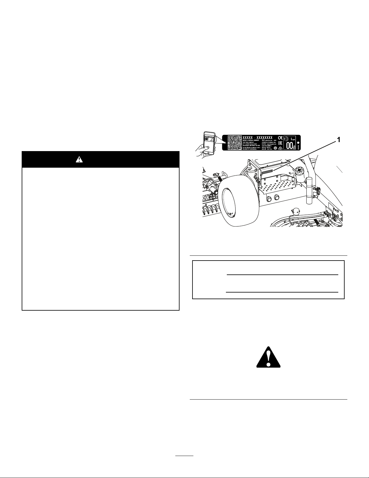
andserialnumbersofyourproductready.Figure1
identiesthelocationofthemodelandserialnumbers
ontheproduct.Writethenumbersinthespace
provided.
Important:Withyourmobiledevice,youcan
scantheQRcodeontheserialnumberdecal(if
equipped)toaccesswarranty,parts,andother
productinformation.
g240238
Figure1
1.Modelandserialnumberlocation
ModelNo.
SerialNo.
Introduction
Thismachineisaride-on,reel-bladelawnmower
intendedtobeusedbyprofessional,hiredoperators
incommercialapplications.Itisprimarilydesigned
forcuttinggrassonwell-maintainedturf.Usingthis
productforpurposesotherthanitsintendedusecould
provedangeroustoyouandbystanders.
Readthisinformationcarefullytolearnhowtooperate
andmaintainyourproductproperlyandtoavoid
injuryandproductdamage.Youareresponsiblefor
operatingtheproductproperlyandsafely .
©2019—TheToro®Company
8111LyndaleAvenueSouth
Bloomington,MN55420
Thismanualidentiespotentialhazardsandhas
safetymessagesidentiedbythesafety-alertsymbol
(Figure2),whichsignalsahazardthatmaycause
seriousinjuryordeathifyoudonotfollowthe
recommendedprecautions.
Figure2
Safety-alertsymbol
Thismanualuses2wordstohighlightinformation.
Importantcallsattentiontospecialmechanical
informationandNoteemphasizesgeneralinformation
worthyofspecialattention.
Contactusatwww.Toro.com.
2
g000502
PrintedintheUSA
AllRightsReserved
Page 3

Contents
Safety.......................................................................4
GeneralSafety...................................................4
Engine-EmissionCertication.............................4
SafetyandInstructionalDecals..........................5
Setup......................................................................13
1InstallingtheCuttingUnits..............................14
2AdjustingtheTurfCompensation
Spring...........................................................16
3InstallingtheCEDecals.................................17
4InstallingtheHoodLatch(CEOnly)................17
5ReducingtheTirePressure............................18
6UsingtheCutting-UnitKickstand....................18
ProductOverview...................................................19
Controls...........................................................19
Specications..................................................23
Attachments/Accessories.................................23
BeforeOperation.................................................24
BeforeOperationSafety...................................24
PerformingDailyMaintenance..........................24
FillingtheFuelTank..........................................24
AdjustingtheSeat............................................25
DuringOperation.................................................26
DuringOperationSafety...................................26
StartingtheEngine...........................................27
ShuttingOfftheEngine.....................................27
SettingtheReelSpeed.....................................27
AdjustingtheLift-ArmCounterbalance.............29
BleedingtheFuelSystem.................................29
UnderstandingtheDiagnosticLight..................30
UnderstandingtheDiagnosticACE
Display..........................................................30
CheckingtheInterlockSwitches.......................30
OperatingTips.................................................32
AfterOperation....................................................33
AfterOperationSafety......................................33
PushingorT owingtheMachine........................33
HaulingtheMachine.........................................34
IdentifyingtheTie-DownPoints........................35
Maintenance...........................................................36
MaintenanceSafety..........................................36
RecommendedMaintenanceSchedule(s)...........36
DailyMaintenanceChecklist.............................38
Pre-MaintenanceProcedures..............................39
RemovingtheHood..........................................39
RemovingtheBatteryCover.............................39
Lubrication..........................................................40
GreasingtheBearingsandBushings................40
EngineMaintenance...........................................41
EngineSafety...................................................41
CheckingtheEngine-OilLevel..........................41
ServicingtheAirCleaner..................................42
ChangingtheEngineOilandFilter....................43
FuelSystemMaintenance...................................43
ServicingtheFuelT ank.....................................43
InspectingtheFuelLinesand
Connections..................................................43
DrainingtheWaterSeparator...........................44
ChangingtheFuelFilterCanister......................44
BleedingAirfromtheInjectors..........................44
ElectricalSystemMaintenance...........................45
ElectricalSystemSafety...................................45
ServicingtheBattery.........................................45
CheckingtheFuses..........................................45
DriveSystemMaintenance..................................46
CheckingtheTirePressure...............................46
TorquingtheWheelNuts...................................46
AdjustingtheTractionDriveforNeutral.............46
CoolingSystemMaintenance..............................47
CoolingSystemSafety.....................................47
CheckingtheCoolingSystem...........................47
CleaningtheEngineCoolingSystem................48
BrakeMaintenance.............................................48
AdjustingtheParkingBrake..............................48
BeltMaintenance................................................49
ServicingtheEngineBelts................................49
ControlsSystemMaintenance.............................50
AdjustingtheThrottle........................................50
HydraulicSystemMaintenance...........................50
HydraulicSystemSafety...................................50
CheckingtheHydraulicLinesand
Hoses............................................................50
CheckingtheHydraulicFluid............................50
HydraulicFluidSpecications...........................51
HydraulicFluidCapacity...................................51
ChangingtheHydraulicFluid............................52
ChangingtheHydraulicFilter............................52
CuttingUnitSystemMaintenance........................53
BladeSafety.....................................................53
CheckingtheReel-to-BedknifeContact............53
UsingtheOptionalGaugeBar..........................54
BacklappingtheCuttingUnits...........................54
Cleaning..............................................................55
WashingtheMachine.......................................55
Storage...................................................................56
StorageSafety..................................................56
PreparingtheTractionUnit...............................56
PreparingtheEngine........................................56
3
Page 4

Safety
Thismachinehasbeendesignedinaccordance
withENISO5395(whenyoucompletethesetup
procedures)andANSIB71.4-2017.
GeneralSafety
Thisproductiscapableofamputatinghandsandfeet
andofthrowingobjects.
•Readandunderstandthecontentsofthis
Operator’sManualbeforestartingtheengine.
•Useyourfullattentionwhileoperatingthe
machine.Donotengageinanyactivitythat
causesdistractions;otherwise,injuryorproperty
damagemayoccur.
•Donotputyourhandsorfeetnearmoving
componentsofthemachine.
•Donotoperatethemachinewithoutallguards
andothersafetyprotectivedevicesinplaceand
functioningproperlyonthemachine.
•Keepbystandersandchildrenoutoftheoperating
area.Neverallowchildrentooperatethemachine.
•Shutofftheengine,removethekey,andwait
forallmovementtostopbeforeyouleavethe
operator’sposition.Allowthemachinetocool
beforeadjusting,servicing,cleaning,orstoringit.
Improperlyusingormaintainingthismachinecan
resultininjury .T oreducethepotentialforinjury,
complywiththesesafetyinstructionsandalways
payattentiontothesafety-alertsymbol
meansCaution,Warning,orDanger—personalsafety
instruction.Failuretocomplywiththeseinstructions
mayresultinpersonalinjuryordeath.
,which
Engine-Emission
Certication
TheengineinthismachineisEP ATier4FinalandEU
StageVemissionscompliant.
4
Page 5
SafetyandInstructionalDecals
99-3444
Safetydecalsandinstructionsareeasilyvisibletotheoperatorandarelocatednearanyarea
ofpotentialdanger.Replaceanydecalthatisdamagedormissing.
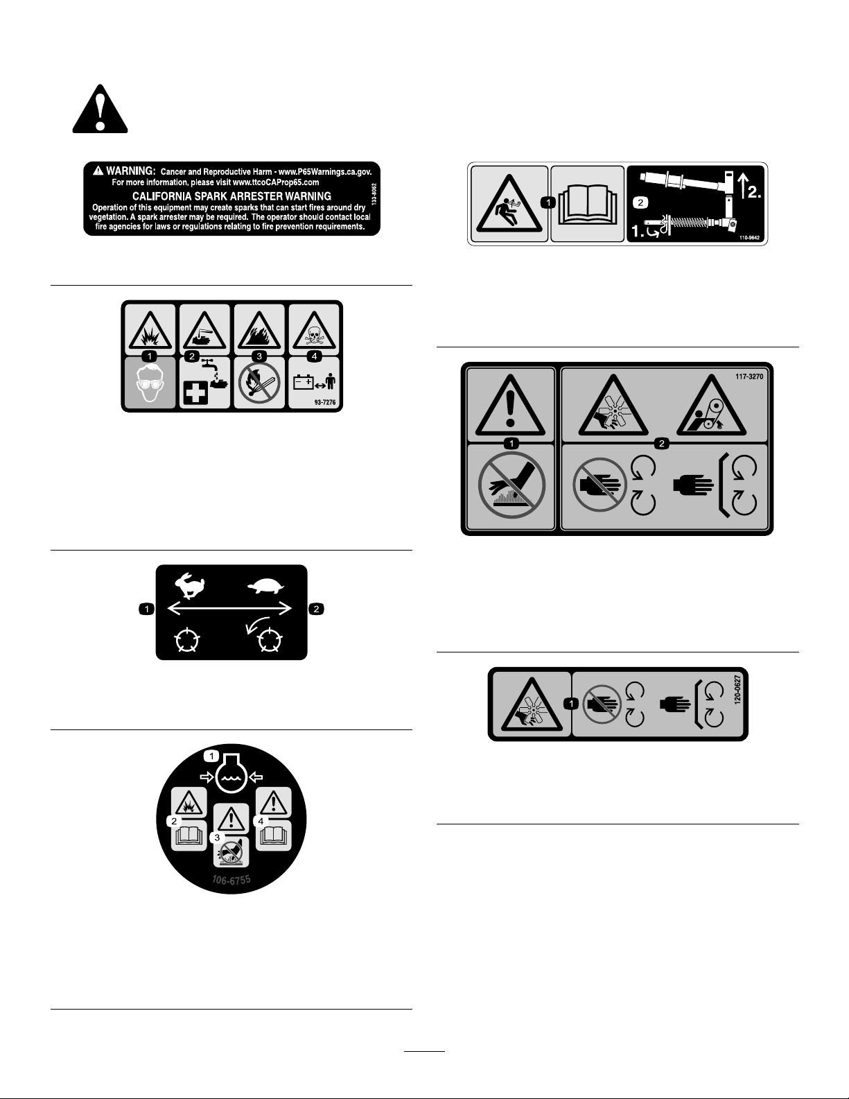
133-8062
93-7276
1.Explosionhazard—weareyeprotection.
2.Causticliquid/chemicalburnhazard—toperformrstaid,
ushwithwater.
3.Firehazard—nore,openames,orsmoking.
4.Poisonhazard—keepchildrenawayfromthebattery .
decal133-8062
decal110-9642
110-9642
1.Storedenergyhazard—readtheOperator'sManual.
2.Movethecotterpintotheholeclosesttotherodbracket
andthenremovetheliftarmandpivotyoke.
decal93-7276
decal117-3270
117-3270
1.Warning—donottouchthehotsurface.
2.Cutting/dismembermenthazard,hand;entanglement
hazard,belt—stayawayfrommovingparts,keepallguards
andshieldsinplace.
1.Transportspeed—fast
1.Enginecoolantunder
pressure.
2.Explosionhazard—read
theOperator'sManual.
decal99-3444
99-3444
2.Mowingspeed—slow
decal120-0627
120-0627
1.Cutting/dismembermenthazard,fan—stayawayfrom
movingparts,keepallguardsandshieldsinplace.
decal106-6755
106-6755
3.Warning—donottouchthe
hotsurface.
4.Warning—readthe
Operator'sManual.
5
Page 6
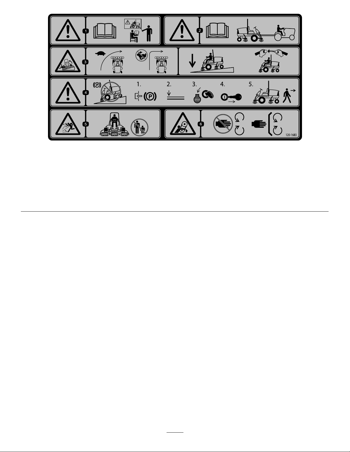
decal120-1683
120-1683
1.Warning—readtheOperator'sManual;alloperatorsshould
betrainedbeforeoperatingthemachine.
2.Warning—readtheOperator'sManualbeforetowingthe
machine.
3.Tippinghazard—driveslowlywhenturning;donotturnsharply
whiletravelingfast;lowerthecuttingunitswhendrivingdown
slopes;usearolloverprotectionsystemandweartheseatbelt.
4.Warning—donotparkthemachineonslopes;engagethe
parkingbrake,lowerthecuttingunits,shutofftheengine,and
removethekeybeforeleavingthemachine.
5.Thrownobjecthazard—keepbystandersaway .
6.Entanglementhazard,belt—stayawayfrommovingparts;
keepallguardsandshieldsinplace.
6
Page 7
decal120-2105
120-2105
1.Lowerthecuttingunits.
2.Raisethecuttingunits.
3.Pulluptoengagethecuttingunits.
4.Pushdowntodisengagethecutting
units.
5.ReadtheOperator’sManualfor
informationonstartingtheengine—sit
intheoperator’sposition,turnthekey
totheenginepreheatposition,wait
untiltheenginepreheatlightturnsoff,
turnthekeytotheenginestartposition,
anddisengagetheparkingbrake.
6.ReadtheOperator’sManual
forinformationonstoppingthe
engine—disengagethecuttingunits,
turnthekeytotheenginestopposition,
removethekeyfromtheignition,and
engagetheparkingbrake.
7.Engine—Shutoff
8.Engine—Preheat
9.Engine—Start
10.Lights
11.Fast
12.Slow
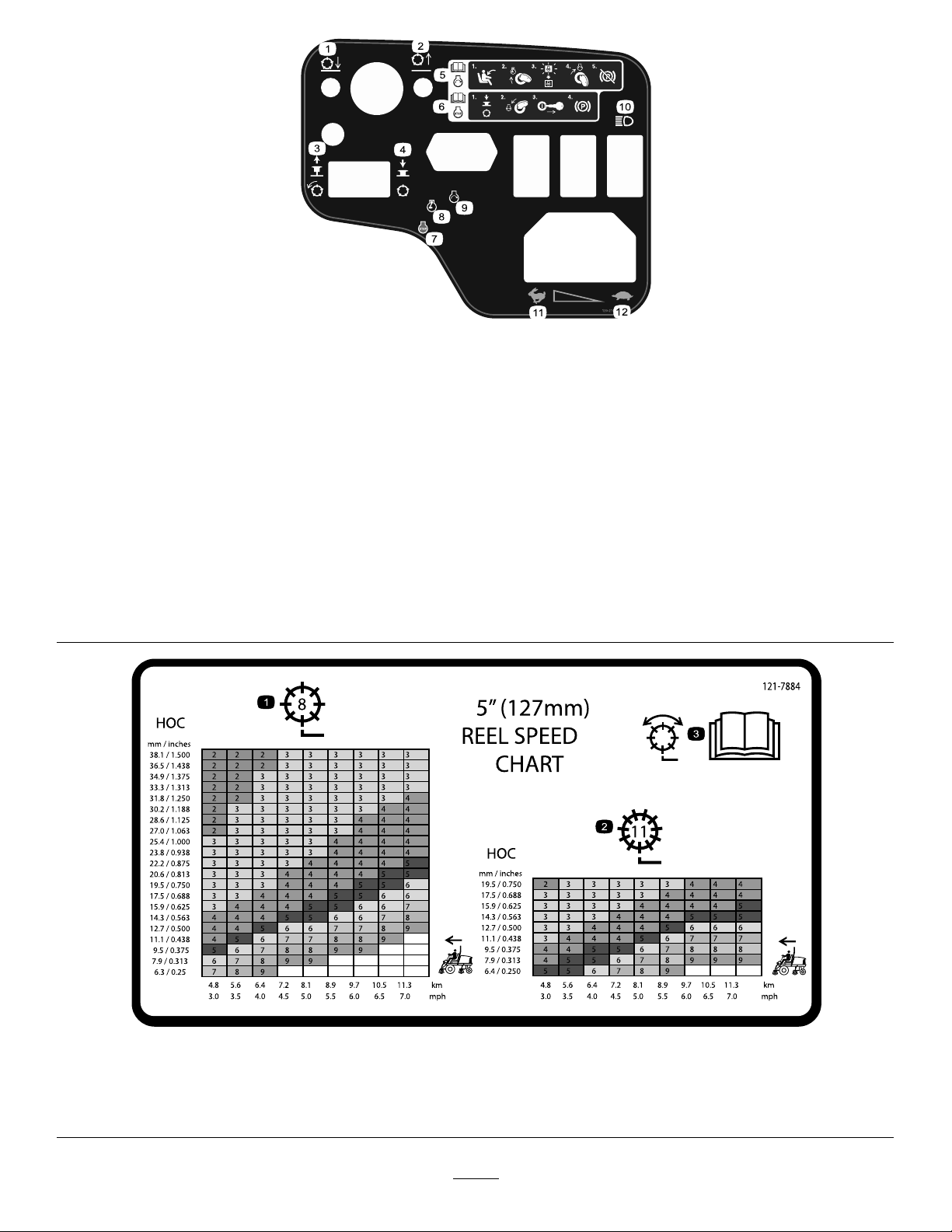
1.8bladereeladjustment
2.11bladereeladjustment
decal121-7884
121–7884
3.ReadtheOperator’sManualforinformationonadjustingthe
reel.
7
Page 8
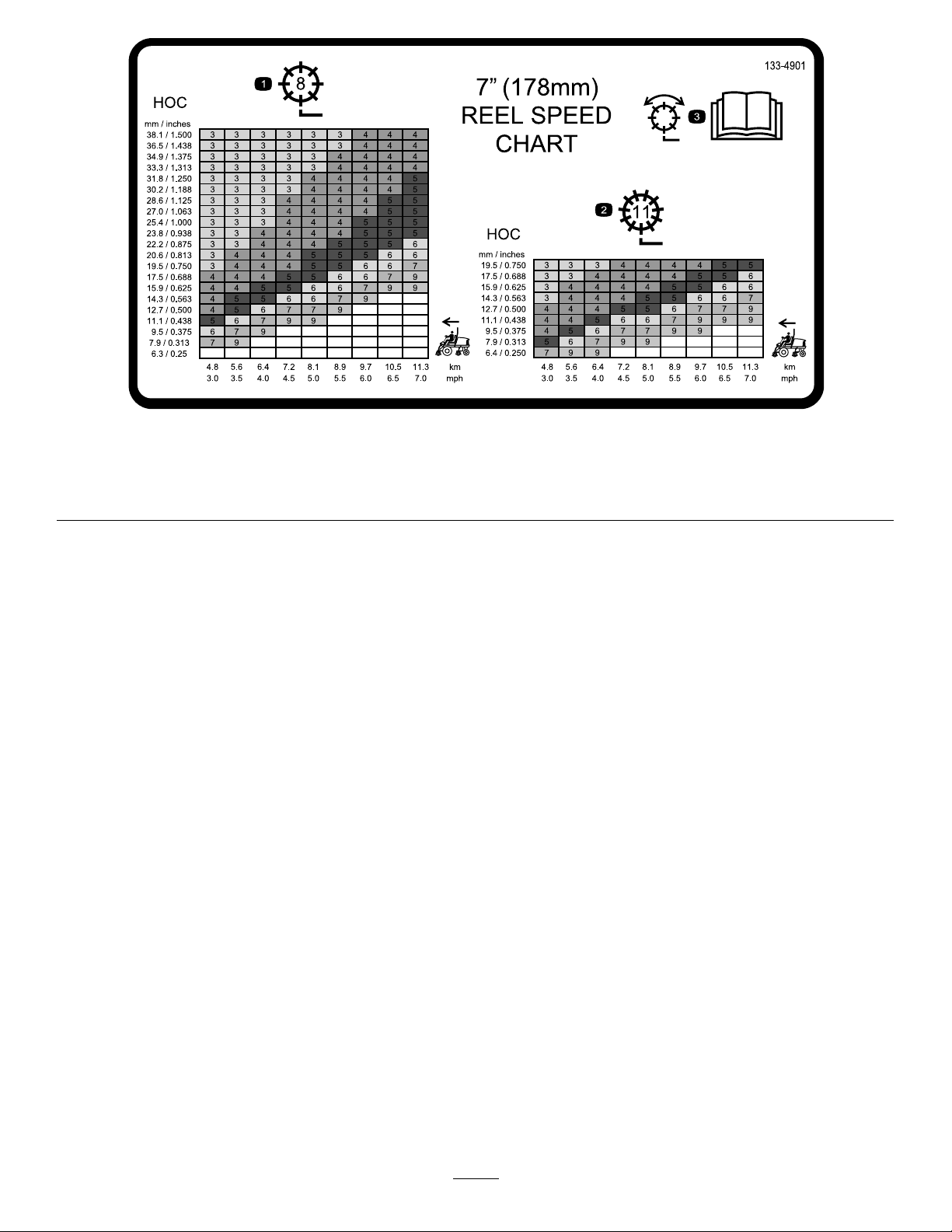
decal133-4901
133-4901
1.8-bladereeladjustment
2.11-bladereeladjustment
3.ReadtheOperator’sManualforinformationonadjustingthe
reel.
8
Page 9
Model03910
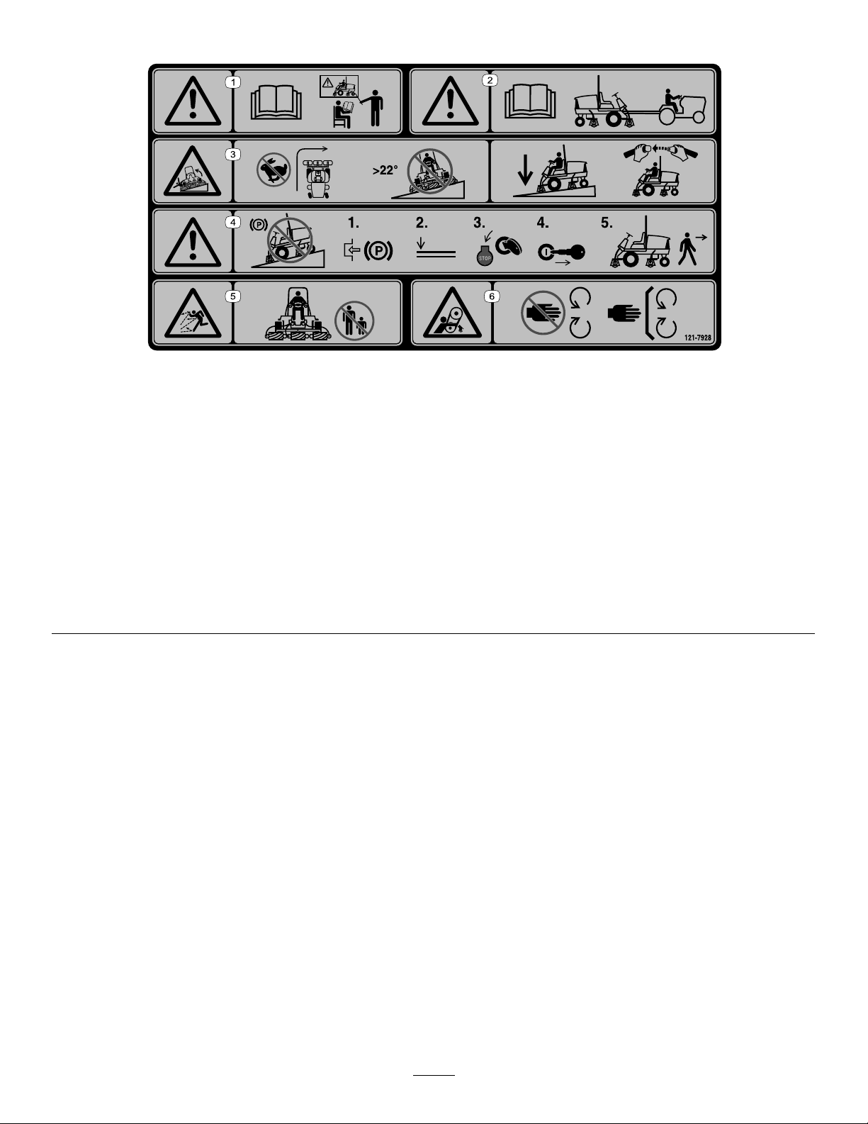
121-7928
Note:Thismachinecomplieswiththeindustrystandardstabilitytestinthestaticlateralandlongitudinaltestswiththemaximum
recommendedslopeindicatedonthedecal.ReviewtheinstructionsforoperatingthemachineonslopesintheOperator’sManualas
wellastheconditionsinwhichyouwouldoperatethemachinetodeterminewhetheryoucanoperatethemachineintheconditions
onthatdayandatthatsite.Changesintheterraincanresultinachangeinslopeoperationforthemachine.Ifpossible,keepthe
cuttingunitsloweredtothegroundwhileoperatingthemachineonslopes.Raisingthecuttingunitswhileoperatingonslopescan
causethemachinetobecomeunstable.
decal121-7928
1.Warning—readtheOperator'sManual;alloperatorsshould
betrainedbeforeoperatingthemachine.
2.Warning—readtheOperator'sManualbeforetowingthe
machine.
3.Tippinghazard—donotturnsharplywhiletravelingfast;do
notdriveupordownslopesgreaterthan22°;lowerthecutting
unitswhendrivingdownslopes;usearolloverprotection
systemandweartheseatbelt.
4.Warning—donotparkthemachineonslopes;engagethe
parkingbrake,lowerthecuttingunits,shutofftheengine,and
removethekeybeforeleavingthemachine.
5.Thrownobjecthazard—keepbystandersaway .
6.Entanglementhazard,belt—stayawayfrommovingparts;
keepallguardsandshieldsinplace.
9
Page 10
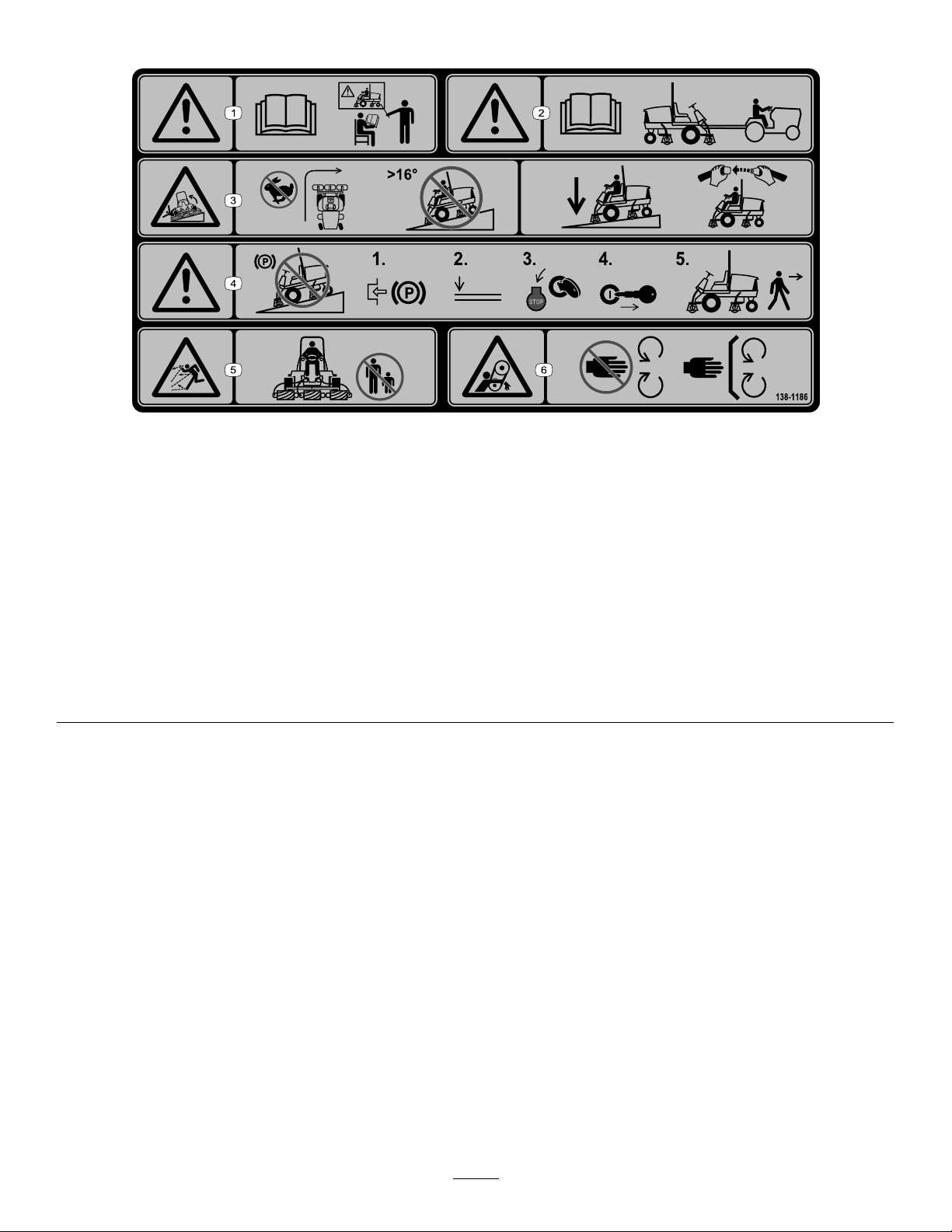
Models03820and03821AfxoverPartNo.120-1683forCE
138-1186
Note:Thismachinecomplieswiththeindustrystandardstabilitytestinthestaticlateralandlongitudinaltestswiththemaximum
recommendedslopeindicatedonthedecal.ReviewtheinstructionsforoperatingthemachineonslopesintheOperator’sManualas
wellastheconditionsinwhichyouwouldoperatethemachinetodeterminewhetheryoucanoperatethemachineintheconditions
onthatdayandatthatsite.Changesintheterraincanresultinachangeinslopeoperationforthemachine.Ifpossible,keepthe
cuttingunitsloweredtothegroundwhileoperatingthemachineonslopes.Raisingthecuttingunitswhileoperatingonslopescan
causethemachinetobecomeunstable.
decal138-1186
1.Warning—readtheOperator'sManual;alloperatorsshould
betrainedbeforeoperatingthemachine.
2.Warning—readtheOperator'sManualbeforetowingthe
machine.
3.Tippinghazard—donotturnsharplywhiletravelingfast;do
notdriveupordownslopesgreaterthan16°;lowerthecutting
unitswhendrivingdownslopes;usearolloverprotection
systemandweartheseatbelt.
4.Warning—donotparkthemachineonslopes;engagethe
parkingbrake,lowerthecuttingunits,shutofftheengine,and
removethekeybeforeleavingthemachine.
5.Thrownobjecthazard—keepbystandersaway .
6.Entanglementhazard,belt—stayawayfrommovingparts;
keepallguardsandshieldsinplace.
10
Page 11
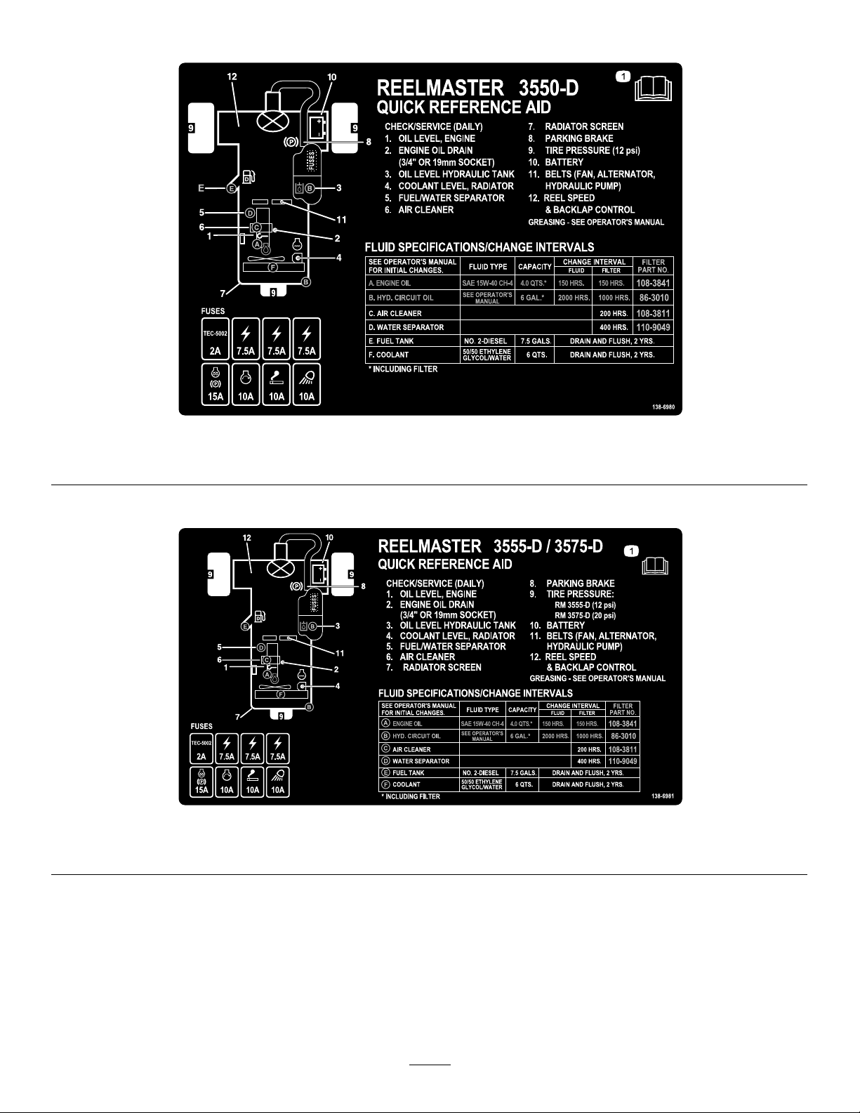
Model03910
decal138-6980
138-6980
1.ReadtheOperator’sManual.
Models03820and03821
1.ReadtheOperator’sManual.
decal138-6981
138-6981
11
Page 12

decalbatterysymbols
BatterySymbols
Someorallofthesesymbolsareonyourbattery .
1.Explosionhazard6.Keepbystandersaway
fromthebattery .
2.Nore,opename,or
smoking
7.Weareyeprotection;
explosivegasescan
causeblindnessandother
injuries.
3.Causticliquid/chemical
burnhazard
8.Batteryacidcancause
blindnessorsevereburns.
4.Weareyeprotection.9.Flusheyesimmediately
withwaterandgetmedical
helpfast.
5.ReadtheOperator's
Manual.
10.Containslead;donot
discard
12
Page 13

Setup
LooseParts
Usethechartbelowtoverifythatallpartshavebeenshipped.
ProcedureDescription
1
2
3
4
5
6
MediaandAdditionalParts
Righthoseguide1
Lefthoseguide
Nopartsrequired
Warningdecal121-7928(machine
model03910)
Warningdecal138-1186(machine
models03820and03821)
CEdecal
Productionyeardecal1
Lockbracket1
Rivet2
Washer1
Screw(1/4x2inches)
Locknut(1/4inch)
Nopartsrequired
Cutting-unitkickstand
Qty.
1
–
1
1
1
1
1
–
1Usethecutting-unitkickstand.
Installthecuttingunits.
Adjusttheturfcompensationspring.
InstalltheCEdecals,ifrequired.
Installthehoodlatch(CEonly).
Reducethetirepressure.
Use
Description
Keys2
Operator'sManual
Engineowner’smanual1
Cuttingperformancepaper
Shim
Qty.
Starttheengine.
1
1
1
Readthemanualsbeforeoperatingthemachine.
Usethepaperforadjustingthecuttingunitreel-to-bedknife
contact.
Usetheshimforadjustingthecuttingunitreel-to-bedknife
contact.
Note:Determinetheleftandrightsidesofthemachinefromthenormaloperatingposition.
Use
13
Page 14
1
InstallingtheCuttingUnits
Partsneededforthisprocedure:
1Righthoseguide
1
Lefthoseguide
compensationspringismountedtothesame
sideofthecuttingunitasthereeldrivemotor.
Positiontheturfcompensationasfollows:
A.Removethe2carriageboltsandnuts
securingtherodbrackettothecuttingunit
tabs(Figure4).
Procedure
1.Parkthemachineonalevelsurface,engagethe
parkingbrake,shutofftheengine,andremove
thekeyfromtheignitionswitch.
2.Removethereelmotorsfromtheshipping
brackets.
3.Removeanddiscardtheshippingbrackets.
4.Removethecuttingunitsfromthecartons.
Assembleandadjustthemasdescribedinthe
cuttingunitOperator'sManual.
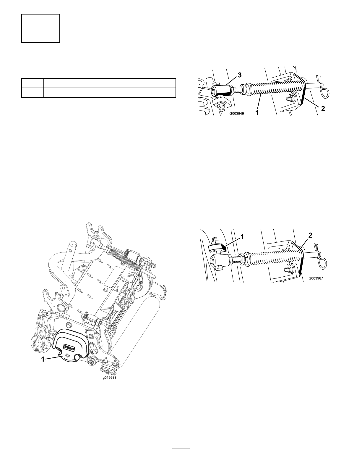
5.Makesurethatthecounterweight(Figure3)is
installedtotheproperendofthecuttingunitas
describedinthecuttingunitOperator'sManual.
g003949
Figure4
1.Turfcompensationspring3.Springtube
2.Rodbracket
B.Removetheangenutsecuringthespring
tubebolttothecarrierframetab(Figure4),
andremovetheassembly .
C.Mountthespringtubebolttotheopposite
tabonthecarrierframeandsecureitwith
theangenut.
Note:Positiontheboltheadtotheouter
sideofthetabasshowninFigure4.
g003967
Figure5
Figure3
1.Counterweight
6.Allthecuttingunitsareshippedwiththeturf
compensationspringmountedtotheright
sideofthecuttingunit.Ensurethattheturf
1.Oppositecarrierframetab
D.Mounttherodbrackettothecuttingunit
tabswiththecarriageboltsandnuts(Figure
5).
2.Rodbracket
Note:Wheninstallingorremovingthecutting
units,makesurethatthehairpincotteris
installedinthespringrodholenexttotherod
bracket.Otherwise,installthehairpincotterin
g019938
14
theholeintheendoftherod.
7.Oncuttingunit4(leftfront)andcuttingunit5
(rightfront),usetherod-bracketmountingnuts
toinstallthehoseguidestothefrontofthe
cutting-unittabs.Thehoseguidesshouldlean
towardthecentercuttingunit(Figure6,Figure
7,Figure8).
Page 15
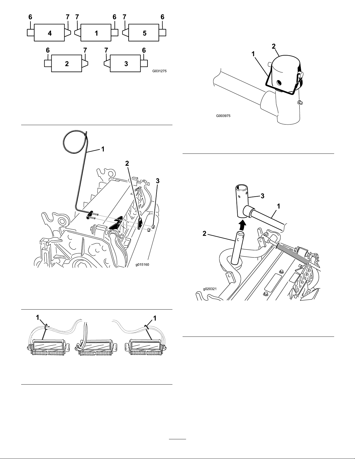
Figure6
1.Cuttingunit15.Cuttingunit5
2.Cuttingunit2
3.Cuttingunit3
4.Cuttingunit4
6.Reelmotor
7.Weight
8.Loweralltheliftarmscompletely.
9.Removethesnapperpinandthecapfromthe
lift-armpivotyoke(Figure9).
g031275
g003975
Figure9
1.Snapperpin2.Cap
10.Forthefrontcuttingunits,slideacuttingunit
undertheliftarmwhileinsertingthecarrierframe
shaftupintothelift-armpivotyoke(Figure10).
Figure7
1.Hoseguide(leftside
shown)
2.Rodbracket
3.Nuts
Figure8
1.Hoseguides(eachmustleantowardthecentercuttingunit)
g015160
g020321
Figure10
1.Liftarm3.Lift-armpivotyoke
2.Carrierframeshaft
11.Usethefollowingprocedureontherearcutting
unitswhentheheightofcutisabove1.2cm
g289454
(3/4inch).
A.Removethelynchpinandwashersecuring
thelift-armpivotshafttotheliftarmand
slidethelift-armpivotshaftoutofthelift
arm(Figure11).
15
Page 16
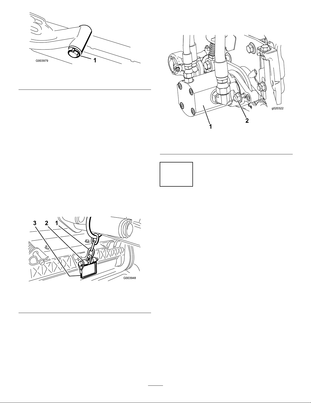
Figure11
1.Lift-armshaftlynchpinandwasher
B.Insertthelift-armyokeontothecarrier
frameshaft(Figure10).
C.Insertthelift-armshaftintotheliftarmand
secureitwiththewasherandlynchpin
(Figure1 1).
12.Insertthecapoverthecarrierframeshaftand
lift-armyoke.
13.Securethecapandthecarrierframeshafttothe
lift-armyokewiththesnapperpin.
Important:Makesurethatthereelmotor
hosesarenottwisted,kinked,oratriskof
beingpinched.
g003979
g020322
Figure13
1.Reel-drivemotor2.Mountingnuts
Note:Usetheslotifasteeringcuttingunitis
desiredorusetheholeifthecuttingunitistobe
lockedinposition(Figure9).
14.Securethelift-armchaintothechainbracket
withthesnapperpin(Figure12).
Note:Usethenumberofchainlinksspecied
inthecuttingunitOperator'sManual.
Figure12
1.Lift-armchain3.Snapperpin
2.Chainbracket
2
AdjustingtheTurf
CompensationSpring
NoPartsRequired
Procedure
Theturfcompensationspring(Figure14)transfers
weightfromthefronttotherearroller.Thishelps
toreduceawavepatternintheturf,alsoknownas
marcellingorbobbing.
g003948
Important:Makespringadjustmentswiththe
cuttingunitmountedtothetractionunit,pointing
straightaheadandloweredtotheshopoor.
1.Makesurethatthehairpincotterisinstalledin
therearholeinthespringrod(Figure14).
15.Coatthesplineshaftofthereelmotorwithclean
grease.
16.Oilthereel-motorO-ringandinstallitontothe
motorange.
17.Installthemotorbyrotatingitclockwisesothat
themotorangesclearthelocknuts(Figure
13).Rotatethemotorcounterclockwiseuntilthe
angesencirclethenuts,thentightenthenuts.
16
Page 17
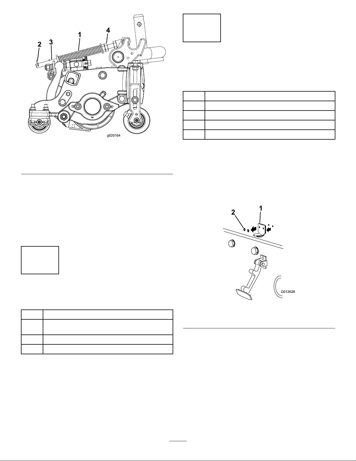
Figure14
4
InstallingtheHoodLatch
(CEOnly)
Partsneededforthisprocedure:
1Lockbracket
2Rivet
1Washer
1
Screw(1/4x2inches)
1
g020164
Locknut(1/4inch)
1.Turfcompensationspring3.Springrod
2.Hairpincotter4.Hexnuts
2.Tightenthehexnutsonthefrontendofthe
springroduntilthecompressedlengthofthe
spring(Figure14)is12.7cm(5inches)for
5-inchcuttingunitsand15.8cm(6-1/4inches)
for7-inchcuttingunits.
Note:Whenoperatingonroughterrain,
decreasethespringlengthby2.5cm(1/2inch).
Groundfollowingwillbeslightlydecreased.
3
InstallingtheCEDecals
Partsneededforthisprocedure:
1
Warningdecal121-7928(machinemodel03910)
Warningdecal138-1186(machinemodels03820and
1
03821)
1
CEdecal
1Productionyeardecal
Procedure
1.Unhookthehoodlatchfromthehood-latch
bracket.
2.Removethe2rivetssecuringthehood-latch
brackettothehood(Figure15)andremovethe
hood-latchbracketfromthehood.
g012628
Figure15
1.Hood-latchbracket2.Rivets
3.Whilealigningthemountingholes,positionthe
CElockbracketandthehood-latchbracketonto
thehood.
Procedure
OnmachinesrequiringCEcompliance,applythe
productionyeardecal(PartNo.133-5615)nearthe
serialplate,theCEdecal(PartNo.93-7252)near
thehoodlock,andtheCEwarningdecal(PartNo.
121-7928formachinemodel03910andPartNo.
138-1186formachinemodels03820and03821)over
thestandardwarningdecal(PartNo.120-1683).
Note:Thelockbracketmustbeagainstthe
hood(Figure16).Donotremovetheboltand
nutfromthelock-bracketarm.
17
Page 18
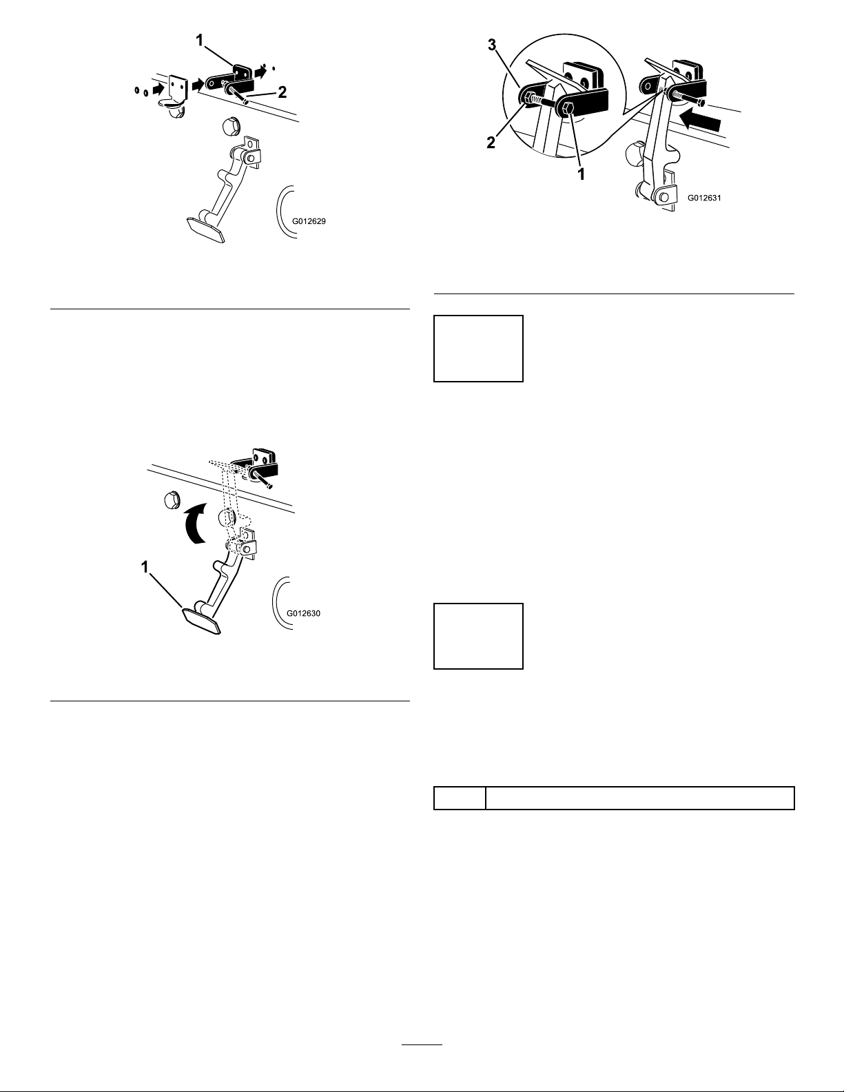
Figure16
1.CElockbracket
4.Alignthewasherswiththeholesontheinsideof
thehood.
2.Boltandnut
g012631
Figure18
g012629
1.Bolt
2.Nut
3.Armofhood-lockbracket
5.Rivetthebracketsandthewasherstothehood
(Figure16).
6.Hookthelatchontothehood-latchbracket
(Figure17).
Figure17
1.Hoodlatch
7.Screwtheboltintotheotherarmofthehood-lock
brackettolockthelatchinposition(Figure18).
Note:Tightentheboltsecurelybutdonot
tightenthenut.
5
ReducingtheTirePressure
NoPartsRequired
Procedure
Thetiresareoverinatedatthefactoryforshipping
purposes.Reducethepressuretotheproperlevels
beforestartingthemachine;refertoCheckingtheTire
Pressure(page46).
g012630
6
UsingtheCutting-Unit
Kickstand
Partsneededforthisprocedure:
1
Cutting-unitkickstand
Procedure
Wheneveryoutipacuttingunittoexposethe
bedknife/reel,propuptherearofthecuttingunitwith
thekickstandtoensurethatthenutsonthebackend
ofthebedbaradjustingscrewsarenotrestingonthe
worksurface(Figure19).
18
Page 19

ProductOverview
g216864
Figure21
Figure19
1.Cutting-unitkickstand
Securethekickstandtothechainbracketwiththe
snapperpin(Figure20).
1.Enginehood
g020158
2.Seat
3.Controlarm
4.Steeringwheel
5.Seatadjustmentlever
6.Frontcuttingunits
7.Rearcuttingunits
Controls
g020079
Figure22
Figure20
1.Chainbracket3.Cutting-unitkickstand
2.Snapperpin
1.Forwardtractionpedal
2.Reversetractionpedal4.Tilt-steeringlever
g004144
3.Mow/transportslide
TractionPedals
Presstheforwardtractionpedal(Figure22)tomove
forward.Pressreversetractionpedal(Figure22)to
movebackwardortoassistinstoppingwhenmoving
forward.Also,allowthepedaltomoveormoveitto
theNEUTRALpositiontostopthemachine.
19
Page 20

Mow/TransportSlide
Usingyourheel,movethemow/transportslide(Figure
22)tothelefttotransportandtotherighttomow.The
cuttingunitswillonlyoperateintheMOWposition
andnotlowerintheTRANSPORTposition.
Important:Themowspeedissetatthefactoryto
9.7km/h(6mph).Itcanbeincreasedordecreased
byadjustingthespeedstopscrew(Figure23).
g019980
Figure24
Figure23
1.Speedstopscrew
Tilt-SteeringLever
Pullthetilt-steeringlever(Figure22)backtotiltthe
steeringwheeltothedesiredposition.Thenpushthe
leverforwardtosecuretheposition.
IgnitionSwitch
Theignitionswitch(Figure24),usedtostart,shut
off,andpreheattheengine,has3positions:OFF,
ON/PREHEAT,andSTART.Rotatethekeytothe
ON/PREHEATpositionuntiltheglow-plugindicator
lightgoesout(approximately7seconds);thenrotate
thekeytotheST ARTpositiontoengagethestarter
motor.Releasethekeywhentheenginestarts.The
keymovesautomaticallytotheON/RUNposition.T o
shutofftheengine,rotatethekeytotheOFFposition.
Removethekeyfromtheswitchtopreventaccidental
starting.
1.Parkingbrake
g008888
2.Ignitionswitch8.Temperaturelight
3.Enable/Disableswitch
4.Diagnosticlight
5.Lowermow/raisecontrol
lever
6.Hourmeter12.Alternatorlight
7.Oil-pressurelight
9.Lightswitch
10.Glow-plugindicatorlight
11.Throttle
Throttle
Movethethrottle(Figure24)forwardtoincreasethe
enginespeedandrearwardtodecreasetheengine
speed.
Enable/DisableSwitch
Usetheenable/disableswitch(Figure24)in
conjunctionwiththelowermow/raisecontrollever
tooperatethecuttingunits.Youcannotlowerthe
cuttingunitswhenthemow/transportleverisin
theTRANSPORTposition.
HourMeter
Thehourmeter(Figure24)indicatesthetotalhours
ofmachineoperation.Itstartstofunctionwhenever
thekeyswitchison.
LowerMow/RaiseControlLever
Thislever(Figure24)raisesandlowersthecutting
unitsandalsostartsandstopsthereelswhenthe
reelsareenabledinthemowmode.Youcannot
lowerthecuttingunitswhenthemow/transport
leverisintheTRANSPORTposition.
Note:Whenthecuttingunitsareenabled,youdonot
needtoholdtheleverintheforwardpositionwhilethe
cuttingunitsareloweredorraised.
20
Page 21

EngineCoolantTemperature
DiagnosticLight
WarningLight
Thetemperaturewarninglight(Figure24)glows
iftheenginecoolanttemperatureishigh.Atthis
temperature,thecuttingunitsaredisabled.Ifthe
coolanttemperaturerisesanother5.5°C(10°F),the
engineshutsofftopreventfurtherdamage.
Oil-PressureWarningLight
Theoil-pressurewarninglight(Figure24)glowsifthe
engineoilpressuredropsbelowasafelevel.
AlternatorLight
Thealternatorlight(Figure24)shouldbeoffwhen
theengineisrunning.Ifitison,checkthecharging
systemandrepairitasnecessary.
Glow-PlugIndicator
Theglow-plugindicatorlight(Figure24)glowswhen
theglowplugsareoperating.
Thediagnosticlight(Figure24)willilluminateifthe
systemrecognizesasystemfault.
FuelGauge
Thefuelgauge(Figure25)indicatestheamountof
fuelinthetank.
g019982
Figure25
1.Fuelgauge
PowerPoint
ParkingBrake
Whenevertheengineisshutoff,engagetheparking
brake(Figure24)topreventaccidentalmovementof
themachine.T oengagetheparkingbrake,pullup
onthelever.Theenginestopswhenyoupressthe
tractionpedalwiththeparkingbrakeengaged.
Thepowerpoint,locatedontheoutsideofthecontrol
panel,isa12Vpowersupplyforelectronicdevices
(Figure26).
g019983
Figure26
1.Powerpoint
21
Page 22

ReelSpeedControlKnob
Thereelspeedcontrolcontrolsthespeedofthe
cuttingunits(Figure27).Thereelspeedincreases
asyouturntheknobcounterclockwise.Refertothe
reelspeedchartdecal(Figure30),todeterminethe
properreelspeed.
Figure27
1.Backlaplever2.Reelspeedcontrolknob
BacklapLever
Usethebacklapleverinconjunctionwiththelower
mow/raisecontrolleverforthereels(Figure27).
g020248
22
Page 23

Specications
Note:Specicationsanddesignaresubjectto
changewithoutnotice.
DimensionsReelmaster3550Reelmaster3555Reelmaster3575
WidthofCut208cm(82inches)254cm(100inches)254cm(100inches)
OverallWidth239cm(94inches)284cm(112inches)284cm(1 12inches)
TransportWidth
OverallLength295cm(110inches)267cm(105inches)267cm(105inches)
HeighttotopofROPS188cm(74inches)201cm(79inches)206cm(81inches)
WheelBase
Weight(congured)900kg(1985lb)1034kg(2280lb)1 157kg(2550lb)
Weight(nocuttingunits)708kg(1560lb)751kg(1655lb)796kg(1755lb)
Attachments/Accessories
AselectionofT oroapprovedattachmentsand
accessoriesisavailableforusewiththemachine
toenhanceandexpanditscapabilities.Contact
yourAuthorizedServiceDealerorauthorizedT oro
distributororgotowww.Toro.comforalistofall
approvedattachmentsandaccessories.
231cm(91inches)231cm(91inches)231cm(91inches)
151cm(59.5inches)152cm(60inches)152cm(60inches)
Toensureoptimumperformanceandcontinuedsafety
certicationofthemachine,useonlygenuineT oro
replacementpartsandaccessories.Replacement
partsandaccessoriesmadebyothermanufacturers
couldbedangerous,andsuchusecouldvoidthe
productwarranty.
23
Page 24

Operation
PerformingDaily
Maintenance
BeforeOperation
BeforeOperationSafety
GeneralSafety
•Neverallowchildrenoruntrainedpeopleto
operateorservicethemachine.Localregulations
mayrestricttheageoftheoperator.Theowner
isresponsiblefortrainingalloperatorsand
mechanics.
•Becomefamiliarwiththesafeoperationofthe
equipment,operatorcontrols,andsafetysigns.
•Shutofftheengine,removethekey,andwait
forallmovementtostopbeforeyouleavethe
operator’sposition.Allowthemachinetocool
beforeadjusting,servicing,cleaning,orstoringit.
•Knowhowtostopthemachineandshutoffthe
enginequickly.
•Donotoperatethemachinewithoutallguards
andothersafetyprotectivedevicesinplaceand
functioningproperlyonthemachine.
•Beforemowing,alwaysinspectthemachineto
ensurethatthecuttingunitsareingoodworking
condition.
•Inspecttheareawhereyouwillusethemachine
andremoveallobjectsthatthemachinecould
throw.
FuelSafety
•Useextremecareinhandlingfuel.Itisammable
anditsvaporsareexplosive.
•Extinguishallcigarettes,cigars,pipes,andother
sourcesofignition.
•Useonlyanapprovedfuelcontainer.
•Donotremovethefuelcaporllthefueltank
whiletheengineisrunningorhot.
•Donotaddordrainfuelinanenclosedspace.
•Donotstorethemachineorfuelcontainerwhere
thereisanopename,spark,orpilotlight,such
asonawaterheaterorotherappliance.
•Ifyouspillfuel,donotattempttostarttheengine;
avoidcreatinganysourceofignitionuntilthefuel
vaporshavedissipated.
ServiceInterval:Beforeeachuseordaily
Beforestartingthemachineeachday ,performthe
EachUse/DailyprocedureslistedinMaintenance
(page36).
FillingtheFuelTank
Useonlyclean,freshdieselfuelorbiodieselfuelswith
low(<500ppm)orultra-low(<15ppm)sulfurcontent.
Theminimumcetaneratingshouldbe40.Purchase
fuelinquantitiesthatcanbeusedwithin180days
toensurefuelfreshness.
Thefueltankcapacityisapproximately42L(1 1US
gallons).
Usesummer-gradedieselfuel(Number2-D)at
temperaturesabove-7°C(20°F)andwinter-grade
dieselfuel(Number1-DorNumber1-D/2-Dblend)
below-7°C(20°F).Usingwinter-gradefuelatlower
temperaturesprovideslowerashpointandcoldow
characteristicswhichwilleasestartingandreduce
pluggingofthefuellter.
Usingsummer-gradefuelabove-7°C(20°F)will
contributetowardlongerfuel-pumplifeandincreased
powercomparedtowinter-gradefuel.
Themachineisbiodieselready.
Thismachinecanalsouseabiodieselblendedfuel
ofuptoB20(20%biodiesel,80%petrodiesel).The
petrodieselportionshouldbeloworultra-lowsulfur.
Observethefollowingprecautions:
•Thebiodieselportionofthefuelmustmeet
specicationASTMD6751orEN14214.
•TheblendedfuelcompositionshouldmeetASTM
D975orEN590.
•Paintedsurfacesmaybedamagedbybiodiesel
blends.
•UseB5(biodieselcontentof5%)orlesserblends
incoldweather.
•Monitorseals,hoses,andgasketsincontactwith
fuelastheymaydegradeovertime.
•Expectpluggingofthefuellterforatimeafter
convertingtobiodieselblends.
•ContactyourauthorizedT orodistributorifyouwish
formoreinformationonbiodiesel.
1.Parkthemachineonalevelsurface,lowerthe
cuttingunits,engagetheparkingbrake,shutoff
theengine,andremovethekeyfromtheignition
switch.
2.Cleantheareaaroundthefuel-tankcap(Figure
28).
24
Page 25

3.Removethefuel-tankcap.
4.Fillthetanktothebottomofthellerneck.Do
notoverllthetank.
5.Installthecap.
6.T opreventarehazard,wipeupanyfuelthat
mayhavespilled.
Figure28
1.Fuel-tankcap
AdjustingtheSeat
Raisethearmrestandturntheknob,ineither
direction,toprovidethebestcomfort(Figure29).
g008884
ChangingtheSeatPosition
Theseatcanmoveforwardandbackward.Position
theseatwhereyouhavethebestcontrolofthe
machineandaremostcomfortable.
1.Movetheleversidewaystounlocktheseat
(Figure29).
2.Slidetheseattothedesiredpositionandrelease
thelevertolockitinposition.
ChangingtheSeatSuspension
Youcanadjusttheseattoprovideasmoothand
comfortableride.Positiontheseatwhereyouare
mostcomfortable.
Toadjustit,turnthefrontknobineitherdirectionto
providethebestcomfort(Figure29).
ChangingtheBackPosition
Youcanadjustthebackoftheseattoprovidea
comfortableride.Positionthebackoftheseatwhere
itismostcomfortable.
1.Backrestknob
2.Seat-positionadjustment
lever
g010515
Figure29
3.Seat-suspensionknob
4.Armrest-adjustingknob
Toadjustit,turntheknobundertherightarmrest,in
eitherdirection,toprovidethebestcomfort(Figure
29).
ChangingtheArmrestPosition
Youcanadjustthearmreststoprovideacomfortable
ride.Positionthearmrestswheretheyaremost
comfortable.
25
Page 26

DuringOperation
DuringOperationSafety
–Waitforallmovementtostop.
•Operatethemachineonlyingoodvisibilityand
appropriateweatherconditions.Donotoperate
themachinewhenthereistheriskoflightning.
GeneralSafety
•Theowner/operatorcanpreventandisresponsible
foraccidentsthatmaycausepersonalinjuryor
propertydamage.
•Wearappropriateclothing,includingeye
protection;longpants;substantial,slip-resistant
footwear;andhearingprotection.Tiebacklong
hairanddonotwearlooseclothingorloose
jewelry.
•Donotoperatethemachinewhileill,tired,or
undertheinuenceofalcoholordrugs.
•Useyourfullattentionwhileoperatingthe
machine.Donotengageinanyactivitythat
causesdistractions;otherwise,injuryorproperty
damagemayoccur.
•Beforeyoustarttheengine,ensurethatalldrives
areinneutral,theparkingbrakeisengaged,and
youareintheoperatingposition.
•Donotcarrypassengersonthemachineandkeep
bystandersandchildrenoutoftheoperatingarea.
•Operatethemachineonlyingoodvisibilitytoavoid
holesorhiddenhazards.
•Avoidmowingonwetgrass.Reducedtraction
couldcausethemachinetoslide.
•Keepyourhandsandfeetawayfromthecutting
units.
•Lookbehindanddownbeforebackinguptobe
sureofaclearpath.
•Usecarewhenapproachingblindcorners,shrubs,
trees,orotherobjectsthatmayobscureyour
vision.
•Stopthecuttingunitswheneveryouarenot
mowing.
•Slowdownandusecautionwhenmakingturns
andcrossingroadsandsidewalkswiththe
machine.Alwaysyieldtheright-of-way.
•Operatetheengineonlyinwell-ventilatedareas.
Exhaustgasescontaincarbonmonoxide,which
islethalifinhaled.
•Donotleavearunningmachineunattended.
•Beforeyouleavetheoperator’sposition,dothe
following:
–Parkthemachineonalevelsurface.
–Disengagethecuttingunit(s)andlowerthe
attachments.
–Engagetheparkingbrake.
–Shutofftheengineandremovethekey .
RolloverProtectionSystem
(ROPS)Safety
•DonotremoveanyoftheROPScomponentsfrom
themachine.
•Ensurethattheseatbeltisattachedandthatyou
canreleaseitquicklyinanemergency.
•Alwayswearyourseatbelt.
•Checkcarefullyforoverheadobstructionsanddo
notcontactthem.
•KeeptheROPSinsafeoperatingconditionby
thoroughlyinspectingitperiodicallyfordamage
andkeepingallthemountingfastenerstight.
•ReplacealldamagedROPScomponents.Donot
repairoralterthem.
SlopeSafety
•Slopesareamajorfactorrelatedtolossofcontrol
androlloveraccidents,whichcanresultinsevere
injuryordeath.Youareresponsibleforsafeslope
operation.Operatingthemachineonanyslope
requiresextracaution.
•Evaluatethesiteconditionstodetermineifthe
slopeissafeformachineoperation,including
surveyingthesite.Alwaysusecommonsense
andgoodjudgmentwhenperformingthissurvey .
•Reviewtheslopeinstructions,listedbelow,for
operatingthemachineonslopes.Beforeyou
operatethemachine,reviewthesiteconditionsto
determinewhetheryoucanoperatethemachine
intheconditionsonthatdayandatthatsite.
Changesintheterraincanresultinachangein
slopeoperationforthemachine.
–Avoidstarting,stopping,orturningthemachine
onslopes.Avoidmakingsuddenchangesin
speedordirection.Maketurnsslowlyand
gradually.
–Donotoperateamachineunderanyconditions
wheretraction,steering,orstabilityisin
question.
–Removeormarkobstructionssuchasditches,
holes,ruts,bumps,rocks,orotherhidden
hazards.T allgrasscanhideobstructions.
Uneventerraincouldoverturnthemachine.
–Beawarethatoperatingthemachineonwet
grass,acrossslopes,ordownhillmaycause
themachinetolosetraction.
–Useextremecautionwhenoperating
themachineneardrop-offs,ditches,
26
Page 27

embankments,waterhazards,orother
hazards.Themachinecouldsuddenlyrollover
ifawheelgoesovertheedgeortheedge
cavesin.Establishasafetyareabetweenthe
machineandanyhazard.
–Identifyhazardsatthebaseoftheslope.
Iftherearehazards,mowtheslopewitha
pedestrian-controlledmachine.
–Ifpossible,keepthecuttingunitsloweredto
thegroundwhileoperatingonslopes.Raising
thecuttingunitswhileoperatingonslopescan
causethemachinetobecomeunstable.
StartingtheEngine
Youmayneedtobleedthefuelsystemifanyofthe
followingsituationshaveoccurred;refertoBleeding
theFuelSystem(page29):
•Initialstartupofanewengine
CAUTION
Contactwithmovingpartscouldresult
ininjury.
Shutofftheengineandwaitforall
movingpartstostopbeforechecking
foroilleaks,looseparts,andother
malfunctions.
ShuttingOfftheEngine
1.MovethethrottlecontroltotheIDLEposition.
2.MovethecuttingunitdriveswitchtoDISENGAGE.
3.RotatethekeytoOFF.
4.Removethekeytopreventaccidentalstarting.
SettingtheReelSpeed
•Theenginehasceasedrunningduetolackoffuel.
•Maintenancehasbeenperformeduponthefuel
systemcomponents;i.e.lterreplaced,etc.
1.Ensurethattheparkingbrakeisengagedand
thecuttingunitdriveswitchisintheDISENGAGE
position.
2.Removeyourfootfromthetractionpedaland
ensurethatthepedalisintheNEUTRALposition.
3.Movethethrottlelevertothe1/2throttleposition.
4.Insertthekeyintotheswitchandrotateitto
theON/PREHEA Tpositionuntiltheglow-plug
indicatorlightgoesout(approximately7
seconds);thenrotatethekeytotheSTART
positiontoengagethestartermotor.
Note:Releasethekeywhentheenginestarts.
ThekeywillmoveautomaticallytotheON/RUN
position.
Important:Topreventoverheatingofthe
startermotor,donotengagethestarterfor
longerthan15seconds.After10secondsof
continuouscranking,wait60secondsbefore
engagingthestartermotoragain.
Toachieveaconsistent,highqualityofcutanda
uniformafter-cutappearance,itisimportantthatyou
setthereelspeedcontrols(locatedundertheseat)
correctly.Adjustthereelspeedcontrolsasfollows:
1.Selecttheheightofcutatwhichthecuttingunits
areset.
2.Choosethedesiredgroundspeedbestsuited
forconditions.
3.Usethegraphonthereelspeedchartdecals
(Figure30andFigure31),todeterminethe
properreelspeedsetting.
5.Whentheengineisstartedforthersttime
orafteranoverhauloftheengine,operate
themachineinforwardandreversefor1to2
minutes.Alsooperatetheliftleverandcutting
unitdriveswitchtoensureproperoperationof
allparts.
Turnthesteeringwheeltotheleftandright
tochecksteeringresponse;thenshutoffthe
engineandcheckforoilleaks,looseparts,and
anyothernoticeablemalfunctions.
27
Page 28

Figure30
Model03820and03910
decal121-7884
1.8-bladereeladjustment
2.11-bladereeladjustment
3.ReadtheOperator’sManualforinformationonadjustingthe
reel.
decal133-4901
Figure31
Model03821
1.8-bladereeladjustment
2.11-bladereeladjustment
4.T osetthereelspeed,rotatetheknob(Figure
32)untiltheindicatorarrowisinlinewiththe
numberdesignatingthedesiredsetting.
3.ReadtheOperator’sManualforinformationonadjustingthe
reel.
28
Page 29

Figure33
g034346
Figure32
1.Reelspeedcontrolknob
Note:Thereelspeedcanbeincreasedor
decreasedtocompensateforturfconditions.
Whenusingbaskets,increasethereelspeedto
improvecollectionperformance.
AdjustingtheLift-Arm
Counterbalance
Youcanadjustthecounterbalanceontheliftarmsof
therearcuttingunitstocompensatefordifferentturf
conditionsandtomaintainauniformheightofcutin
roughconditionsorinareasofthatchbuildup.
Youcanadjusteachcounterbalancespringto1of
4settings.Eachincrementincreasesordecreases
counterbalanceonthecuttingunitby2.3kg(5lb).
Youcanpositionthespringsonthebacksideofthe
rstspringactuatortoremoveallcounterbalance
(fourthposition).
1.Parkthemachineonalevelsurface,lowerthe
cuttingunits,engagetheparkingbrake,shutoff
theengine,andremovethekeyfromtheignition
switch.
2.Insertatubeorsimilarobjectontothelong
springendtorelievethespringtensionduring
theadjustment(Figure33).
1.Spring
2.Springactuator
g020259
4.Movethespringactuatortothedesiredhole
locationandsecureitwiththeboltandthe
locknut.
5.Repeattheprocedureontheremainingspring.
3.Additionalholelocations
BleedingtheFuelSystem
1.Parkthemachineonalevelsurface,lowerthe
cuttingunits,engagetheparkingbrake,shutoff
theengine,andremovethekey.
2.Ensurethatthefueltankisatleasthalffull.
3.Unlatchandraisethehood.
4.Opentheair-bleedscrewonthefuel-injection
pump(Figure34).
g008891
Figure34
CAUTION
Thespringsareundertensionandcould
causepersonalinjury.
Usecautionwhenadjustingthem.
3.Whilerelievingthespringtension,removethe
boltandlocknutsecuringthespringactuatorto
thebracket(Figure33).
1.Fuel-injectionpumpbleedscrew
5.TurnthekeyintheignitionswitchtotheON
position.Theelectricfuelpumpwillbegin
operation,therebyforcingairoutaroundthe
air-bleedscrew.
Note:LeavethekeyintheONpositionuntila
solidstreamoffuelowsoutaroundthescrew.
29
Page 30

6.Tightenthescrewandturntheignitionkeyto
OFF.
Note:Normallytheengineshouldstartafterthe
abovebleedingproceduresarefollowed.However,if
theenginedoesnotstart,airmaybetrappedbetween
theinjectionpumpandinjectors;refertoBleedingAir
fromtheInjectors(page44).
•Fusesareblown.
•Itisnotfunctioningcorrectly .
Checktheelectricalconnections,inputfuses,and
diagnosticlightbulbtodeterminethemalfunction.
Ensurethattheloop-backconnectorissecuredto
thewireharnessconnector.
Understandingthe
DiagnosticLight
Themachineisequippedwithadiagnosticlight
thatindicatesiftheelectroniccontrollersensesan
electronicmalfunction.Thediagnosticlightislocated
onthecontrolpanel(Figure35).Whentheelectronic
controllerisfunctioningcorrectlyandyoumovethe
keyswitchtotheONposition,thecontrollerdiagnostic
lightturnsonfor3secondsandturnofftoindicate
thatthelightisworkingproperly.Iftheengineshuts
off,thenthelightturnsonsteadyuntiltheyouchange
keyposition.Thelightblinksifthecontrollerdetectsa
malfunctionintheelectricalsystem.Thelightstops
blinkingandautomaticallyresetswhenyouturnthe
keyswitchtotheOFFpositiononcethefaulthasbeen
resolved.
Figure35
1.Diagnosticlight
Understandingthe
DiagnosticACEDisplay
Themachineisequippedwithanelectroniccontroller
whichcontrolsmostmachinefunctions.Thecontroller
determineswhatfunctionisrequiredforvariousinput
switches(i.e.,seatswitch,keyswitch,etc.)andturns
ontheoutputstoactuatesolenoidsorrelaysforthe
requestedmachinefunction.
Fortheelectroniccontrollertocontrolthemachineas
desired,eachoftheinputswitches,outputsolenoids,
andrelaysmustbeconnectedandfunctioning
properly.
UsetheDiagnosticACEdisplaytohelpverifyand
correctelectricalfunctionsofthemachine.
CheckingtheInterlock
Switches
ServiceInterval:Beforeeachuseordaily
Thepurposeoftheinterlockswitchesistopreventthe
enginefromcrankingorstartingunlessthetraction
pedalisintheNEUTRALposition,theEnable/Disable
switchisintheDISABLEposition,andtheLower
Mow/RaisecontrolisintheNEUTRALposition.In
g020251
addition,theengineshouldshutoffwhenyoupress
thetractionpedalwithnooneintheseatorifthe
parkingbrakeisengaged.
Whenthecontrollerdiagnosticlightblinks,1of
thefollowingproblemshasbeendetectedbythe
controller:
•Anoutputhasbeenshorted.
•Anoutputisopencircuited.
Usingthediagnosticdisplay ,determinewhichoutput
ismalfunctioning;refertoCheckingtheInterlock
Switches(page30).
Ifthediagnosticlightisnotilluminatedwhenthekey
switchisintheONposition,thisindicatesthatthe
electroniccontrollerisnotoperating.Possiblecauses
areasfollows:
•Theloop-backisnotconnected.
•Thelightisburnedout.
CAUTION
Ifsafetyinterlockswitchesaredisconnected
ordamaged,themachinecouldoperate
unexpectedly,causingpersonalinjury.
•Donottamperwiththeinterlockswitches.
•Checktheoperationoftheinterlock
switchesdailyandreplaceanydamaged
switchesbeforeoperatingthemachine.
VerifyingtheInterlockSwitch
Function
1.Parkthemachineonalevelsurface,lowerthe
cuttingunits,engagetheparkingbrake,and
shutofftheengine.
30
Page 31

2.Removethecoverfromthecontrolpanel.
3.Locatethewireharnessandloop-back
connector(Figure36).
Figure36
1.Loop-backconnector
4.Carefullyunplugtheloop-backconnectorfrom
theharnessconnector.
5.ConnecttheDiagnosticACEdisplayconnector
totheharnessconnector(Figure37).
Note:Ensurethatthecorrectoverlaydecalis
positionedontheDiagnosticACEdisplay.
DiagnosticACE,tochangeLEDto“inputs
displayed.”
TheDiagnosticACEilluminatestheLED
associatedwitheachoftheinputswhenthat
inputswitchisclosed.
8.Individually ,changeeachoftheswitchesfrom
opentoclosed(i.e.,sitontheseat,engage
thetractionpedal,etc.),andnotethatthe
appropriateLEDontheDiagnosticACEblinks
onandoffwhenthecorrespondingswitchis
closed.Repeatthisforallswitchesthatyoucan
changebyhand.
9.Ifaswitchisclosedandtheappropriate
LEDdoesnotturnon,checkallwiringand
connectionstotheswitchand/orcheckthe
switcheswithanohmmeterormultimeter.
g020260
Replaceanymalfunctioningswitchesandrepair
anymalfunctioningwiring.
Note:TheDiagnosticACEalsohastheability
todetectwhichoutputsolenoidsorrelaysare
turnedon.Thisisaquickwaytodetermineifa
machinemalfunctioniselectricalorhydraulic.
VerifyingOutputFunction
1.Parkthemachineonalevelsurface,lowerthe
cuttingunits,engagetheparkingbrake,shutoff
theengine,andremovethekey.
Figure37
1.DiagnosticACE
6.TurnthekeyswitchtotheONposition,butdo
notstartthemachine.
Note:Theredtextontheoverlaydecalrefers
toinputswitchesandthegreentextrefersto
outputs.
7.The“inputsdisplayed”LED,onthelowerright
columnoftheDiagnosticACE,shouldbe
illuminated.Ifthe“outputsdisplayed”LED
isilluminated,pressthetogglebutton,on
2.Removetheaccesspanelfromthesideofthe
controlarm.
3.Locatethewireharnessandconnectorsnear
thecontroller.
4.Carefullyunplugtheloop-backconnectorfrom
theharnessconnector.
5.ConnecttheDiagnosticACEconnectortothe
harnessconnector.
Note:Makesurethatthecorrectoverlaydecal
ispositionedontheDiagnosticACE.
6.TurnthekeyswitchtotheONposition,butdo
g004140
notstartthemachine.
Note:Theredtextontheoverlaydecalrefers
toinputswitchesandthegreentextrefersto
outputs.
7.The“outputsdisplayed”LED,onlower
rightcolumnofDiagnosticACE,shouldbe
illuminated.Ifthe“inputsdisplayed”LEDis
illuminated,pressthetogglebutton,onthe
DiagnosticACE,tochangetheLEDto“outputs
displayed”.
Note:Itmaybenecessarytotogglebetween
“inputsdisplayed”and“outputsdisplayed”
severaltimestodothefollowingstep.T otoggle
31
Page 32

backandforth,pressthetogglebuttononce.
Thismaybedoneasoftenasrequired.Donot
holdthebutton.
8.Sitontheseatandattempttooperatethe
desiredfunctionofthemachine.Theappropriate
outputLEDsshouldilluminatetoindicatethat
theECMisturningonthatfunction.
Note:IfthecorrectoutputLEDsdonot
illuminate,verifythattherequiredinputswitches
areinthenecessarypositionstoallowthat
functiontooccur.Verifycorrectswitchfunction.
IftheoutputLEDsareonasspecied,but
themachinedoesnotfunctionproperly ,this
indicatesanon-electricalproblem.Repairas
necessary.
Note:Ifeachoutputswitchisinthecorrect
positionandfunctioningcorrectly,buttheoutput
LEDsarenotcorrectlyilluminated,thisindicates
anECMproblem.Ifthisoccurs,contactyour
authorizedT orodistributorforassistance.
Important:TheDiagnosticACEdisplay
mustnotbeleftconnectedtothemachine.It
isnotdesignedtowithstandtheenvironment
oftheeverydayuseofthemachine.When
youarenishedusingtheDiagnosticACE,
disconnectitfromthemachineandconnect
theloop-backconnectortotheharness
connector.Themachinedoesnotoperate
withouttheloop-backconnectorinstalledon
theharness.StoretheDiagnosticACEina
dry,securelocationintheshop,notonthe
machine.
OperatingTips
BecomingFamiliarwiththe
Machine
Beforemowinggrass,practiceoperatingthemachine
inanopenarea.Startandshutofftheengine.
Operateinforwardandreverse.Lowerandraise
thecuttingunitsandengageanddisengagethe
cuttingunits.Whenyoufeelfamiliarwiththemachine,
practiceoperatingupanddownslopesatdifferent
speeds.
UnderstandingtheWarning
System
Ifawarninglightcomesonduringoperation,stopthe
machineimmediatelyandcorrecttheproblembefore
continuingoperation.Seriousdamagecouldoccurif
youoperatethemachinewithamalfunction.
MowingGrass
StarttheengineandmovethethrottletotheFAST
position.MovetheEnable/Disableswitchtothe
ENABLEpositionandusetheLowerMow/Raiselever
tocontrolthecuttingunits(thefrontcuttingunits
aretimedtolowerbeforetherearcuttingunits).To
moveforwardandcutgrass,pressthetractionpedal
forward.
DrivingtheMachineinTransport
Mode
MovetheEnable/DisableswitchtotheDISABLE
positionandraisethecuttingunitstothetransport
position.MovetheMow/Transportlevertothe
TRANSPORTposition.Becarefulwhendrivingbetween
objectssothatyoudonotaccidentallydamagethe
machineorthecuttingunits.Useextracarewhen
operatingthemachineonslopes.Driveslowlyand
avoidsharpturnsonslopestopreventrollovers.
32
Page 33

AfterOperation
AfterOperationSafety
ThefollowingT oropartsareneededtobypassthe
checkvalve:
•ToroPartNo.59-7410,diagnostictting
•ToroPartNo.354-79,diagnostic-ttingcap
GeneralSafety
•Shutofftheengine,removethekey,andwait
forallmovementtostopbeforeyouleavethe
operator’sposition.Allowthemachinetocool
beforeadjusting,servicing,cleaning,orstoringit.
•Cleangrassanddebrisfromthecuttingunits,
drives,mufers,coolingscreens,andengine
compartmenttohelppreventres.Cleanupoilor
fuelspills.
•Shutoffthefuelwhilestoringorhaulingthe
machine.
•Disengagethedrivetotheattachmentwhenever
youarehaulingornotusingthemachine.
•Maintainandcleantheseatbelt(s)asnecessary.
•Donotstorethemachineorfuelcontainerwhere
thereisanopename,spark,orpilotlight,such
asonawaterheateroronotherappliances.
PushingorTowingthe
Machine
Inanemergency ,youcanmovethemachine
byactuatingthebypassvalveinthevariable
displacementhydraulicpumpandinstallinga
hydraulichosetobypassthecheckvalve,andthen
pushingortowingthemachine.
Important:Donotpushortowthemachinefaster
than3to4.8km/h(2to3mph)orformorethan
0.4km(1/4mile),becauseinternaltransmission
damagemayoccur.Thebypassvalvemustbe
openwheneveryoupushortowthemachine.
Additionally,youneedtoinstallahydraulichose
tobypassthecheckvalvewheneveryoupushor
towthemachineinreverse.
•ToroPartNo.95-8843,hydraulichose
•ToroPartNo.95-0985,couplertting(2)
•ToroPartNo.340-77,hydraulictting(2)
1.Installadiagnosticttingintheunmarkedport
locatedbetweenportsM8andP2ontherear
tractionmanifold(Figure38).
Figure38
1.Reartractionmanifold
(behindfrontleftwheel)
2.Connectahydraulichosebetweenthe
diagnosticttinginstalledinthereartraction
manifoldandthereversetractionpressuretest
port(Figure39).
2.Unmarkedport
Note:Usethehydraulicttingsandcoupler
ttingsasneededtoinstallthehose.
g033131
Ifyouneedtopushortowyourmachine,youwill
likelyneedtomoveitbothforwardandinreverse.
Toensurethatthedrivesystemdoesnotbecome
damagedfrompushingortowing,itisbesttoprepare
themachineforbothforwardandreversepushingor
towing.
PreparingtheMachineforPushing
orTowinginReverse
Important:Ifyouneedtopushortowthe
machineinreverse,youmustrstbypassthe
checkvalveinthe4-wheel-drivemanifold.
33
Page 34

Figure39
Note:Donotexceed7to11N∙m(5to8ft-lb)
torquetoclosethevalve.
PushingorTowingtheMachine
ForwardOnly
Ifyouneedtopushortowthemachineforwardonly,
youcanjustrotatethebypassvalve.
Important:Ifyouneedtopushortowthe
machineinreverse,refertoPreparingtheMachine
forPushingorTowinginReverse(page33).
1.Openthehoodandremovethecentershroud.
2.Rotatethebypassvalve90°(1/4turn)ineither
g033132
directiontoopenitandallowuidtobypass
internally(Figure40).
1.Reversetractionpressure
testport
3.Rotatethebypassvalve90°(1/4turn)ineither
directiontoopenitandallowuidtobypass
internally(Figure40).
2.Hydraulicuidreturnlter
Note:Becausetheuidbypassesthe
transmission,youcanmovethemachineslowly
withoutdamagingthetransmission.
Notethepositionofthevalvewhenopeningand
closingit.
Note:Becausetheuidbypassesthe
transmission,youcanmovethemachine
forwardslowlywithoutdamagingthe
transmission.
Notethepositionofthevalvewhenopeningand
closingit.
3.Rotatethebypassvalve90°(1/4turn)back
beforestartingtheengine.
Note:Donotexceed7to11N∙m(5to8ft-lb)
torquetoclosethevalve.
HaulingtheMachine
•Usefull-widthrampsforloadingthemachineonto
atrailerortruck.
•Tiethemachinedownsecurely.
Figure40
1.Bypassvalve
4.Whenyouarenishedpushingortowingthe
machine,removethehydraulichosethatyou
installed.
5.Installtheexistingcapontothereversetraction
pressuretestport.
6.Installthediagnostic-ttingcapontothetting
thatyouinstalledonthemanifold.
7.Rotatethebypassvalve90°(1/4turn)back
beforestartingtheengine.
g009703
34
Page 35

IdentifyingtheTie-Down
Points
1.Tie-downloops
g198911
Figure41
35
Page 36

Maintenance
Note:Determinetheleftandrightsidesofthemachinefromthenormaloperatingposition.
MaintenanceSafety
•Beforeyouleavetheoperator’sposition,dothe
following:
–Parkthemachineonalevelsurface.
–Disengagethecuttingunit(s)andlowerthe
attachments.
–Engagetheparkingbrake.
–Shutofftheengineandremovethekey .
–Waitforallmovementtostop.
•Allowmachinecomponentstocoolbefore
performingmaintenance.
•Ifpossible,donotperformmaintenancewhilethe
engineisrunning.Keepawayfrommovingparts.
RecommendedMaintenanceSchedule(s)
MaintenanceService
Interval
MaintenanceProcedure
•Supportthemachinewithjackstandswhenever
youworkunderthemachine.
•Carefullyreleasepressurefromcomponentswith
storedenergy.
•Keepallpartsofthemachineingoodworking
conditionandallhardwaretightened.
•Replaceallwornordamageddecals.
•Toensuresafe,optimalperformanceofthe
machine,useonlygenuineT ororeplacement
parts.Replacementpartsmadebyother
manufacturerscouldbedangerous,andsuchuse
couldvoidtheproductwarranty .
Afterthersthour
Aftertherst10hours
Aftertherst50hours
Beforeeachuseordaily
Every25hours
Every50hours
Every100hours
Every150hours
Every200hours
•Torquethewheelnuts.
•Torquethewheelnuts.
•Checktheconditionandtensionofallbelts.
•Changetheoilandoillter.
•Inspecttheseatbelt(s)forwear,cuts,andotherdamage.Replacetheseatbelt(s)if
anycomponentdoesnotoperateproperly.
•Checktheinterlocksystem.
•Checktheengine-oillevel.
•Drainthewaterseparator.
•Checkthetirepressure.
•Checktheengine-coolantlevel.
•Cleandebrisoffoftheradiator.
•Checkthehydrauliclinesandhoses.
•Checkthelevelofthehydraulicuid.
•Checkthereel-to-bedknifecontact.
•Checktheelectrolytelevel(ifmachineisinstorage,checkevery30days).
•Lubricateallbearingsandbushings(dailywhenconditionsaredustyanddirty).
•Checktheconditionandtensionofallbelts.
•Changetheoilandoillter.
•Servicetheaircleaner(morefrequentlyinextremelydustyordirtyconditions).
•Torquethewheelnuts.
•Checktheadjustmentoftheparkingbrake.
Every400hours
•Checkthefuellinesandconnections.
•Replacethefuelltercanister.
36
Page 37

MaintenanceService
Every800hours
Interval
MaintenanceProcedure
•Ifyouarenotusingtherecommendedhydraulicuidorhaveeverlledthereservoir
withanalternativeuid,changethehydraulicuid.
•Ifyouarenotusingtherecommendedhydraulicuidorhaveeverlledthereservoir
withanalternativeuid,replacethehydrauliclter.
Every1,000hours
Every2,000hours
Every2years
•Ifyouareusingtherecommendedhydraulicuid,replacethehydrauliclter.
•Ifyouareusingtherecommendedhydraulicuid,changethehydraulicuid.
•Drainandcleanthefueltank.
37
Page 38

DailyMaintenanceChecklist
Duplicatethispageforroutineuse.
Fortheweekof:
MaintenanceCheckItem
Checkthesafetyinterlock
operation.
Checkthebrakeoperation.
Checktheengine-oillevel.
Checkthecoolingsystem
uidlevel.
Drainthewater/fuel
separator.
Checktheairlter,dustcup,
andburpvalve.
Checkforunusualengine
1
noises.
Checktheradiatorfordebris.
Checkforunusualoperating
noises.
Checkthehydraulicsystem
uidlevel.
Checkthehydraulichoses
fordamage.
Checkforuidleaks.
Checkthefuellevel.
Checkthetirepressure.
Checktheinstrument
operation.
Checktheheight-of-cut
adjustment.
Lubricateallthegrease
2
ttings.
Touch-upanydamaged
paint.
Washthemachine.
1
Checktheglowplugandinjectornozzlesifstartingishard,thereisexcesssmoke,orroughrunningisnoted.
2
Immediatelyaftereverywashing,regardlessoftheintervallisted.
Mon.Tues.Wed.Thurs.Fri.
Sat.Sun.
NotationforAreasofConcern
Inspectionperformedby:
ItemDate
1
2
3
4
5
Information
38
Page 39

6
7
8
Important:Refertoyourengineowner’smanualandcuttingunitOperator'sManualforadditional
maintenanceprocedures.
Note:Downloadafreecopyoftheelectricalorhydraulicschematicbyvisitingwww.Toro.comandsearching
foryourmachinefromtheManualslinkonthehomepage.
Pre-Maintenance
Procedures
RemovingtheHood
1.Unlatchandraisethehood.
2.Removethehairpincottersecuringthehood
pivottothemountingbrackets(Figure42).
Figure42
1.Hairpincotter
RemovingtheBattery
Cover
Loosentheknobsandremovethebatterycover
(Figure43).
Note:RefertoServicingtheBattery(page45)for
moreinformation.
g008908
3.Slidethehoodtotherightside,lifttheother
side,andpullitoutofthebrackets.
Note:Reversetheproceduretoinstallthehood.
g034350
Figure43
1.Batterycover
39
Page 40

Lubrication
GreasingtheBearingsand
Bushings
ServiceInterval:Every50hours(dailywhen
conditionsaredustyanddirty).
Parkthemachineonalevelsurface,lowerthecutting
units,engagetheparkingbrake,shutofftheengine,
andremovethekeyfromtheignitionswitch.
LubricatethegreasettingsregularlywithNo.2
lithiumgrease.Lubricatethebearingsandbushings
dailywhenoperatingconditionsareextremelydusty
anddirty.Dustyanddirtyoperatingconditionscould
causedirttogetintothebearingsandbushings,
resultinginacceleratedwear.Lubricatethegrease
ttingsimmediatelyaftereverywashing,regardless
oftheintervalspecied.
Thegreasettinglocationsandquantitiesareas
follows:
g034347
Figure45
•Rearlift-armpivotsandliftcylinders(3eachside);
refertoFigure46.
•Steeringpivot(Figure44)
Figure44
•Frontlift-armpivotsandliftcylinders(3each);
refertoFigure45.
g200803
Figure46
•Cuttingunitpivots(2each);refertoFigure47.
g008897
Figure47
•Neutraladjustmechanism(Figure48)
40
g020393
Page 41

Figure48
EngineMaintenance
EngineSafety
•Shutofftheenginebeforecheckingtheoilor
addingoiltothecrankcase.
•Donotchangethegovernorspeedoroverspeed
theengine.
g008901
CheckingtheEngine-Oil
•Mow/transportslide(Figure49)
Figure49
•Belttensionpivot(Figure50)
Figure50
Level
ServiceInterval:Beforeeachuseordaily
Theengineisshippedwithoilinthecrankcase;
however,theoillevelmustbecheckedbeforeand
aftertheengineisrststarted.
Crankcasecapacityisapproximately3.8L(4USqt)
withthelter.
g008902
g008903
Usehigh-qualityengineoilthatmeetsthefollowing
specications:
•APIClassicationLevelRequired:CH-4,CI-4or
higher.
•Preferredoil:SAE15W-40(above0ºF(-17ºC))
•Alternateoil:SAE10W-30or5W-30(all
temperatures)
Note:ToroPremiumEngineOilisavailablefromyour
distributorineither15W-40or10W-30viscosity.
Note:Thebesttimetochecktheengineoiliswhen
theengineiscoolbeforeithasbeenstartedforthe
day.Ifithasalreadybeenrun,allowtheoiltodrain
backdowntothesumpforatleast10minutesbefore
checking.IftheoillevelisatorbelowtheAddmark
onthedipstick,addoiltobringtheoilleveltothe
Fullmark.Donotoverlltheengine.Iftheoillevel
isbetweentheFullandAddmarks,nooiladdition
isrequired.
1.Parkthemachineonalevelsurface,lowerthe
cuttingunits,engagetheparkingbrake,shutoff
theengine,andremovethekey.
2.Removethedipstick(Figure51)andwipeitwith
acleanrag.
41
Page 42

Figure51
1.Dipstick
3.Pushthedipstickdownintothedipsticktubeand
makesurethatitisseatedfully .Pullthedipstick
outandchecktheoillevel.
4.Iftheoillevelislow,removetheoil-llcap
(Figure52)andgraduallyaddsmallquantitiesof
oil,checkingthelevelfrequently,untilthelevel
reachestheFullmarkonthedipstick.
1.Parkthemachineonalevelsurface,lowerthe
cuttingunits,engagetheparkingbrake,shutoff
theengine,andremovethekey.
2.Releasethelatchessecuringtheair-cleaner
covertotheair-cleanerbody(Figure53).
3.Removethecoverfromtheair-cleanerbody
(Figure53).
4.Beforeremovingthelter,uselow-pressureair
(276kPa[40psi],cleananddry)tohelpremove
g008881
largeaccumulationsofdebrispackedbetween
outsideofprimarylterandthecanister.
Note:Avoidusinghigh-pressureair,which
couldforcedirtthroughthelterintotheintake
tract.Thiscleaningprocesspreventsdebris
frommigratingintotheintakewhenyouremove
theprimarylter.
5.Removeandreplacethelter(Figure53).
Donotcleantheusedelementbecauseitcould
damagetheltermedia.
Figure52
1.Oil-llcap
5.Installtheoil-llcapandclosethehood.
ServicingtheAirCleaner
ServiceInterval:Every200hours(morefrequentlyin
extremelydustyordirtyconditions).
•Checktheair-cleanerbodyfordamagewhich
couldcauseanairleak.Replaceitifitisdamaged.
Checkthewholeintakesystemforleaks,damage,
orloosehoseclamps.
•Servicetheaircleanerattherecommended
serviceintervalorearlierifengineperformance
suffersduetoextremelydusty ,dirtyconditions.
Changingtheairlterbeforeitisnecessaryonly
increasesthechanceofdirtenteringtheengine
whenyouremovethelter.
•Besurethatthecoverisseatedcorrectlyand
sealswiththeair-cleanerbody .
g008882
g002401
Figure53
1.Air-cleanercover2.Filter
6.Inspectthenewlterforshippingdamage,
checkingthesealingendofthelterandthe
body.
Important:Donotuseadamagedelement.
7.Insertthenewlterbyapplyingpressuretothe
outerrimoftheelementtoseatitinthecanister.
Important:Donotapplypressuretothe
exiblecenterofthelter.
8.Cleanthedirt-ejectionportlocatedinthe
removablecover.
9.Removetherubberoutletvalvefromthecover,
cleanthecavityandreplacetheoutletvalve.
42
Page 43

10.Installthecoverorientingtherubberoutletvalve
inadownwardposition—betweenapproximately
5o’clockto7o’clockwhenviewedfromtheend.
11.Securethecoverlatches.
ChangingtheEngineOil
andFilter
FuelSystem
Maintenance
ServicingtheFuelTank
ServiceInterval:Every2years—Drainandcleanthe
fueltank.
ServiceInterval:Aftertherst50hours
Every150hours
1.Parkthemachineonalevelsurface,lowerthe
cuttingunits,engagetheparkingbrake,shutoff
theengine,andremovethekey.
2.Removeeitherdrainplug(Figure54)andlet
theoilowintoadrainpan.Whentheoilstops
owing,installthedrainplug.
Figure54
1.Engine-oildrainplugs
3.Removetheoillter(Figure55).
Parkthemachineonalevelsurface,lowerthecutting
units,engagetheparkingbrake,shutofftheengine,
andremovethekey.
Drainandcleanthetankifthefuelsystembecomes
contaminatedorifthemachinewillbestoredforan
extendedperiodoftime.Usecleanfueltoushout
thetank.
InspectingtheFuelLines
andConnections
ServiceInterval:Every400hours/Y early(whichever
comesrst)
Parkthemachineonalevelsurface,lowerthecutting
units,engagetheparkingbrake,shutofftheengine,
g020086
andremovethekeyfromtheignitionswitch.
Inspectthefuellinesandconnectionsfordeterioration,
damage,orlooseconnections.
Figure55
1.Engineoillter
4.Applyalightcoatofcleanoiltothenewlter
seal,andinstallthelter.
Important:Donotovertightenthelter.
5.Addoiltothecrankcase;refertoCheckingthe
Engine-OilLevel(page41).
g022147
43
Page 44

DrainingtheWater
BleedingAirfromthe
Separator
ServiceInterval:Beforeeachuseordaily
1.Parkthemachineonalevelsurface,lowerthe
cuttingunits,engagetheparkingbrake,shutoff
theengine,andremovethekeyfromtheignition
switch.
2.Placeacleancontainerunderthefuellter.
3.Loosenthedrainvalveonthebottomofthelter
canister(Figure56).
Figure56
Injectors
Note:Usethisprocedureonlyifthefuelsystemhas
beenpurgedofairthroughnormalprimingprocedures
andtheenginedoesnotstart;refertoBleedingthe
FuelSystem(page29).
1.Parkthemachineonalevelsurface,lowerthe
cuttingunits,engagetheparkingbrake,and
shutofftheengine.
2.LoosenthepipeconnectiontotheNo.1nozzle
andholderassembly.
g008913
Figure57
g009880
1.Fuelinjectors
1.Waterseparator/lter
canister
2.Ventplug
4.Tightenthevalveafterdraining.
3.Drainvalve
ChangingtheFuelFilter
Canister
ServiceInterval:Every400hours
1.Parkthemachineonalevelsurface,lowerthe
cuttingunits,engagetheparkingbrake,shutoff
theengine,andremovethekeyfromtheignition
switch.
2.Cleantheareawheretheltercanistermounts
(Figure56).
3.Removetheltercanisterandcleanthe
mountingsurface.
4.Lubricatethegasketontheltercanisterwith
cleanoil.
3.MovethethrottletotheFASTposition.
4.TurnthekeyinthekeyswitchtotheSTART
positionandwatchthefuelowaroundthe
connector.TurnthekeytotheOFFposition
whenthereisacontinuousow.
5.Tightenthepipeconnectorsecurely.
6.Repeattheprocedureontheremainingnozzles.
5.Installtheltercanisterbyhanduntilthegasket
contactsthemountingsurface;thenrotateitan
additional1/2turn.
44
Page 45

ElectricalSystem
Maintenance
ElectricalSystemSafety
•Disconnectthebatterybeforerepairingthe
machine.Disconnectthenegativeterminalrst
andthepositivelast.Connectthepositiveterminal
rstandthenegativelast.
•Chargethebatteryinanopen,well-ventilated
area,awayfromsparksandames.Unplugthe
chargerbeforeconnectingordisconnectingthe
battery.Wearprotectiveclothinganduseinsulated
tools.
ServicingtheBattery
ServiceInterval:Every25hours—Checkthe
electrolytelevel(ifmachineisin
storage,checkevery30days).
Parkthemachineonalevelsurface,lowerthecutting
units,engagetheparkingbrake,shutofftheengine,
andremovethekeyfromtheignitionswitch.
WARNING
Incorrectbatterycableroutingcoulddamage
thetractorandcablescausingsparks.Sparks
cancausethebatterygassestoexplode,
resultinginpersonalinjury.
•Alwaysdisconnectthenegative(black)
batterycablebeforedisconnectingthe
positive(red)cable.
•Alwaysconnectthepositive(red)battery
cablebeforeconnectingthenegative
(black)cable.
Ifcorrosionoccursattheterminals,disconnectthe
cables,negative(–)cablerst,andscrapetheclamps
andterminalsseparately.Connectthecables,positive
(+)cablerst,andcoattheterminalswithpetroleum
jelly.
CheckingtheFuses
Thefusesintheelectricalsystemarelocatedunder
thecontrolpanel.
Maintainthebatteryelectrolytelevelandkeepthetop
ofthebatteryclean.Storethemachinewherethe
temperatureiscoolerratherthanwarmertoprevent
thebatteryfromdischargingmorerapidly .
Maintainthecelllevelwithdistilledordemineralized
water.Donotllthecellsabovethebottomofthesplit
ringinsideeachcell.Installthellercapswiththe
ventspointingtotherear(towardthefueltank).
DANGER
Batteryelectrolytecontainssulfuricacid
whichisfatalifconsumedandcausessevere
burns.
•Donotdrinkelectrolyteandavoidcontact
withskin,eyes,orclothing.Weareye
protectiontoshieldyoureyesandrubber
glovestoprotectyourhands.
•Fillthebatterywherecleanwaterisalways
availableforushingtheskin.
Keepthetopofthebatterycleanbywashingit
periodicallywithabrushdippedinammoniaor
bicarbonateofsodasolution.Flushthetopsurface
withwateraftercleaning.Donotremovetheller
capswhilecleaning.
Thebatterycablesmustbetightontheterminalsto
providegoodelectricalcontact.
45
Page 46

DriveSystem
Maintenance
WARNING
Ifthemachineisnotsupported
adequately,itmayaccidentallyfall,
injuringanyoneunderthemachine.
CheckingtheTirePressure
ServiceInterval:Beforeeachuseordaily
Thetiresareover-inatedforshipping.Therefore,
releasesomeoftheairtoreducethepressure.The
correctairpressureinthetiresis83kPa(12psi).
Note:Maintaintherecommendedpressureinalltires
toensureagoodqualityofcutandpropermachine
performance.
DANGER
Lowtirepressuredecreasesmachinesidehill
stability.Thiscouldcausearollover,which
mayresultinpersonalinjuryordeath.
Donotunder-inatethetires.
TorquingtheWheelNuts
ServiceInterval:Afterthersthour
Aftertherst10hours
Afrontwheelandarearwheelmustbe
raisedofftheground;otherwise,the
machinewillmoveduringadjustment.
3.Loosenthelocknutonthetractionadjustment
cam(Figure58).
g008922
Figure58
1.Tractionadjustmentcam2.Locknut
Every200hours
Torquethewheelnutsto103to127N∙m(76to94
ft-lb).
WARNING
Failuretomaintainpropertorqueofthewheel
nutscouldresultinpersonalinjury.
Maintainpropertorqueofthewheelnuts.
AdjustingtheTraction
DriveforNeutral
Ifthemachinemoveswhenthetractionpedalisinthe
NEUTRALposition,adjustthetractioncam.
1.Parkthemachineonalevelsurface,lowerthe
cuttingunits,engagetheparkingbrake,shutoff
theengine,andremovethekeyfromtheignition
switch.
2.Raiseafrontwheelandarearwheelofftheoor
andplacesupportblocksundertheframe.
WARNING
Theenginemustberunningsothat
youcanmakeanaladjustmentof
thetractionadjustmentcam.Contact
withhotormovingpartscanresultin
personalinjury.
Keepyourhands,feet,face,andother
bodypartsawayfromthemufer,other
hotpartsoftheengine,androtating
parts.
4.Starttheengineandrotatethecamhexinboth
directionstodeterminethemidpositionofthe
neutralspan.
5.Tightenthelocknutsecuringtheadjustment.
6.Shutofftheengine.
7.Removethesupportblocksandlowerthe
machinetotheshopoor.Testdrivethe
machinetoensurethatitdoesnotmovewhen
thetractionpedalisinneutral.
46
Page 47

CoolingSystem
Maintenance
CAUTION
Iftheenginehasbeenrunning,the
pressurized,hotcoolantcanescapeand
causeburns.
CoolingSystemSafety
•Swallowingenginecoolantcancausepoisoning;
keepoutofreachfromchildrenandpets.
•Dischargeofhot,pressurizedcoolantortouching
ahotradiatorandsurroundingpartscancause
severeburns.
–Alwaysallowtheenginetocoolatleast15
minutesbeforeremovingtheradiatorcap.
–Usearagwhenopeningtheradiatorcap,and
openthecapslowlytoallowsteamtoescape.
CheckingtheCooling
System
ServiceInterval:Beforeeachuseordaily
Cleandebrisofftheradiatordaily(Figure59).Clean
theradiatorhourlyifconditionsareextremelydusty
anddirty;refertoCleaningtheEngineCoolingSystem
(page48).
•Donotopentheradiatorcapwhenthe
engineisrunning.
•Usearagwhenopeningtheradiatorcap,
andopenthecapslowlytoallowsteamto
escape.
1.Parkthemachineonalevelsurface,lowerthe
cuttingunits,engagetheparkingbrake,shutoff
theengine,andremovethekey.
2.Checkthecoolantlevelintheexpansiontank
(Figure60).Withacoldengine,thecoolant
levelshouldbeapproximatelymidwaybetween
themarksonthesideofthetank.
3.Ifthecoolantlevelislow,removethe
expansion-tankcapandreplenishthesystem.
Donotoverllthetank.
4.Installtheexpansion-tankcap.
Figure59
1.Radiator
Thecoolingsystemislledwitha50/50solution
ofwaterandpermanentethyleneglycolantifreeze.
Checkthecoolantlevelatthebeginningofeachday
beforestartingtheengine.
Thecapacityofthecoolingsystemisapproximately
5.7L(6USqt).
g008885
Figure60
1.Expansiontank
g019984
47
Page 48

CleaningtheEngine
CoolingSystem
BrakeMaintenance
ServiceInterval:Beforeeachuseordaily
Removedebrisfromtheradiatordaily.Cleanitmore
frequentlyindirtyconditions.
1.Parkthemachineonalevelsurface,lowerthe
cuttingunits,engagetheparkingbrake,shutoff
theengine,andremovethekeyfromtheignition
switch.
2.Raisethehood.
3.Cleantheengineareathoroughlyofalldebris.
4.Cleanbothsidesoftheradiatorthoroughlywith
compressedair(Figure61).
AdjustingtheParking
Brake
ServiceInterval:Every200hours—Checkthe
adjustmentoftheparkingbrake.
1.Parkthemachineonalevelsurface,lowerthe
cuttingunits,engagetheparkingbrake,shutoff
theengine,andremovethekeyfromtheignition
switch.
2.Loosenthesetscrewsecuringtheknobtothe
parking-brakelever(Figure62).
1.Radiator
5.Closethehood.
Figure61
g008923
Figure62
1.Parking-brakelever
2.Knob
g019984
3.Rotatetheknobuntilaforceof133to178N(30
to40lb)isrequiredtoactuatethelever.
4.Tightenthesetscrewaftertheadjustmenthas
beenattained.
3.Setscrew
48
Page 49

BeltMaintenance
ServicingtheEngineBelts
theengine,andremovethekeyfromtheignition
switch.
2.Insertanutdriverorsmallpieceoftubingonto
theendofthebelttensioningspring.
ServiceInterval:Aftertherst10hours—Checkthe
conditionandtensionofallbelts.
Every100hours—Checktheconditionand
tensionofallbelts.
TensioningtheAlternator/FanBelt
1.Parkthemachineonalevelsurface,lowerthe
cuttingunits,engagetheparkingbrake,shutoff
theengine,andremovethekeyfromtheignition
switch.
2.Openthehood.
3.Checkthebelttensionbypressingthebelt
midwaybetweenthealternatorandcrankshaft
pulleys.
Note:With98N(22lb)offorce,thebeltshould
deect11mm(7/16inch).
WARNING
Thespringisunderaheavyloadand
couldcausepersonalinjury
Usecautionwhende-tensioningthe
spring.
3.Pushdownandforwardonthespringend
(Figure64)tounhookitfromthebracketand
releasetensiononthespring.
Figure63
1.Alternator/fanbelt
4.Ifthedeectionisincorrect,completethe
followingproceduretotensionthebelt:
A.Loosentheboltsecuringthebracetothe
engineandtheboltsecuringthealternator
tothebrace.
B.Insertaprybarbetweenthealternatorand
engineandprythealternatoroutward.
C.Whenthepropertensionisachieved,
tightenthealternatorandbraceboltsto
securetheadjustment.
g008917
Figure64
1.Hydrostatdrivebelt
4.Replacethebelt.
g008916
5.Reversetheproceduretotensionthespring.
2.Springend
ReplacingtheHydrostatDriveBelt
1.Parkthemachineonalevelsurface,lowerthe
cuttingunits,engagetheparkingbrake,shutoff
49
Page 50

ControlsSystem
HydraulicSystem
Maintenance
AdjustingtheThrottle
1.Parkthemachineonalevelsurface,lowerthe
cuttingunits,engagetheparkingbrake,shutoff
theengine,andremovethekeyfromtheignition
switch.
2.Positionthethrottleleverrearwardsothatit
stopsagainstthecontrolpanelslot.
3.Loosenthethrottlecableconnectoronthe
injectionpumpleverarm(Figure65).
Maintenance
HydraulicSystemSafety
•Seekimmediatemedicalattentionifuidisinjected
intoskin.Injecteduidmustbesurgicallyremoved
withinafewhoursbyadoctor.
•Ensurethatallhydraulic-uidhosesandlinesare
ingoodconditionandallhydraulicconnections
andttingsaretightbeforeapplyingpressureto
thehydraulicsystem.
•Keepyourbodyandhandsawayfrompinhole
leaksornozzlesthatejecthigh-pressurehydraulic
uid.
•Usecardboardorpapertondhydraulicleaks.
•Safelyrelieveallpressureinthehydraulicsystem
beforeperforminganyworkonthehydraulic
system.
CheckingtheHydraulic
Figure65
1.Injectionpumpleverarm
4.Holdtheinjectionpumpleverarmagainstthe
lowidlestopandtightenthecableconnector.
5.Loosenthescrewssecuringthethrottlecontrol
tothecontrolpanel.
6.Pushthethrottlecontrolleveralloftheway
forward.
7.Slidethestopplateuntilitcontactsthethrottle
leverandtightenthescrewssecuringthethrottle
controltothecontrolpanel.
8.Ifthethrottledoesnotstayinpositionduring
operation,torquethelocknut,usedtosetthe
frictiondeviceonthethrottlelever,to5to6N∙m
(44to53in-lb).
Note:Themaximumforcerequiredtooperate
thethrottlelevershouldbe89N(20lb).
LinesandHoses
ServiceInterval:Beforeeachuseordaily
g020336
Checkthehydrauliclinesandhosesforleaks,kinked
lines,loosemountingsupports,wear,loosettings,
weatherdeterioration,andchemicaldeterioration.
Makeallnecessaryrepairsbeforeoperating.
CheckingtheHydraulic
Fluid
ServiceInterval:Beforeeachuseordaily—Check
thelevelofthehydraulicuid.
Thereservoirislledatthefactorywithhigh-quality
hydraulicuid.Thebesttimetocheckthehydraulic
oiliswhentheuidiscold.Themachineshouldbein
itstransportconguration.
1.Parkthemachineonalevelsurface,lowerthe
cuttingunits,engagetheparkingbrake,shutoff
theengine,andremovethekey.
2.Cleantheareaaroundthellerneckandcapof
thehydraulictank(Figure66).
50
Page 51

HighViscosityIndex/LowPourPoint
Anti-wearHydraulicFluid,ISOVG46
MaterialProperties:
Viscosity,ASTMD445cSt@40°C(104°F)
ViscosityIndexASTMD2270
44to48
140orhigher
Figure66
1.Hydraulic-tankcap
3.Removethecap.
4.Removethedipstickfromthellerneckand
wipeitwithacleanrag.Insertthedipstickinto
thellerneck;thenremoveitandchecktheuid
level.Theuidlevelshouldbewithin6mm(1/4
inch)ofthemarkonthedipstick.
5.Ifthelevelislow,addtheappropriateuidto
raisetheleveltothefullmark.
6.Installthedipstickandcapontothellerneck.
HydraulicFluid
Specications
PourPoint,ASTMD97-37°Cto-45°C(-34°F
IndustrySpecications:EatonVickers694(I-286-S,
M-2950-S/35VQ25or
g008886
to-49°F)
M-2952-S)
Note:Manyhydraulicuidsarealmostcolorless,
makingitdifculttospotleaks.Areddyeadditivefor
thehydraulicuidisavailablein20ml(0.67oz)
bottles.Abottleissufcientfor15to22L(4to6US
gallons)ofhydraulicuid.OrderPartNo.44-2500
fromyourauthorizedTorodistributor.
Important:T oroPremiumSynthetic
BiodegradableHydraulicFluidistheonly
syntheticbiodegradableuidapprovedbyToro.
Thisuidiscompatiblewiththeelastomersused
inTorohydraulicsystemsandissuitablefora
wide-rangeoftemperatureconditions.Thisuidis
compatiblewithconventionalmineraloils,butfor
maximumbiodegradabilityandperformance,the
hydraulicsystemshouldbethoroughlyushed
ofconventionaluid.Theoilisavailablein19L
(5USgallon)pailsor208L(55USgallon)drums
fromyourauthorizedTorodistributor.
Thereservoirislledatthefactorywithhigh-quality
hydraulicuid.Checkthelevelofthehydraulicuid
beforeyourststarttheengineanddailythereafter;
refertoCheckingtheHydraulicFluid(page50).
Recommendedhydraulicuid:T oroPXExtended
LifeHydraulicFluid;availablein19L(5USgallon)
pailsor208L(55USgallon)drums.
Note:Amachineusingtherecommended
replacementuidrequireslessfrequentuidandlter
changes.
Alternativehydraulicuids:IfToroPXExtended
LifeHydraulicFluidisnotavailable,youmayuse
anotherconventional,petroleum-basedhydraulicuid
havingspecicationsthatfallwithinthelistedrange
forallthefollowingmaterialpropertiesandthatit
meetsindustrystandards.Donotusesyntheticuid.
Consultwithyourlubricantdistributortoidentifya
satisfactoryproduct.
Note:T orodoesnotassumeresponsibilityfor
damagecausedbyimpropersubstitutions,souse
productsonlyfromreputablemanufacturerswhowill
standbehindtheirrecommendation.
HydraulicFluidCapacity
22.7L(6USgallons);refertoHydraulicFluid
Specications(page51)
51
Page 52

ChangingtheHydraulic
Fluid
ServiceInterval:Every2,000hours—Ifyou
areusingtherecommended
hydraulicuid,changethe
hydraulicuid.
Every800hours—Ifyouarenotusingthe
recommendedhydraulicuidorhaveever
lledthereservoirwithanalternativeuid,
changethehydraulicuid.
WARNING
Hothydraulicuidcancausesevereburns.
Allowthehydraulicuidtocoolbefore
performinganymaintenancetothehydraulic
system.
Important:Useonlythehydraulicuids
specied.Otheruidscouldcausesystem
damage.
g008886
Figure68
1.Hydraulicllcap
Iftheuidbecomescontaminated,contactyour
localTorodistributorbecausethesystemmustbe
ushed.Contaminateduidlooksmilkyorblackwhen
comparedtocleanoil.
1.Parkthemachineonalevelsurface,lowerthe
cuttingunits,engagetheparkingbrake,shutoff
theengine,andremovethekeyfromtheignition
switch.
2.Disconnectthelargehydraulichose(Figure67)
fromthereservoirandletthehydraulicuidow
intoadrainpan.
5.Installthereservoircap.Starttheengineand
useallofthehydrauliccontrolstodistributethe
hydraulicuidthroughoutthesystem.
6.Checkforleaks;thenshutofftheengine.
7.Checktheuidlevelandaddenoughtoraise
theleveltoFullmarkonthedipstick.
Important:Donotoverllthereservoir.
ChangingtheHydraulic
Filter
ServiceInterval:Every1,000hours—Ifyou
areusingtherecommended
hydraulicuid,replacethe
hydrauliclter.
Every800hours—Ifyouarenotusingthe
recommendedhydraulicuidorhaveever
lledthereservoirwithanalternativeuid,
replacethehydrauliclter.
Figure67
1.Hydraulichose
3.Installthehydraulichosewhenhydraulicuid
stopsdraining.
4.Fillthereservoir(Figure68)withapproximately
22.7L(6USgallons)ofhydraulicuid;referto
HydraulicFluidSpecications(page51).
WARNING
Hothydraulicuidcancausesevereburns.
Allowthehydraulicuidtocoolbefore
g020253
performinganymaintenancetothehydraulic
system.
UseagenuineT ororeplacementlter,PartNo.
86-3010.
Important:Useofanyotherltermayvoidthe
warrantyonsomecomponents.
1.Parkthemachineonalevelsurface,lowerthe
cuttingunits,engagetheparkingbrake,shutoff
52
Page 53

theengine,andremovethekeyfromtheignition
switch.
CuttingUnitSystem
2.Cleanaroundtheltermountingarea.Placea
drainpanunderthelter(Figure69)andremove
thelter.
Figure69
1.Hydrauliclter
Maintenance
BladeSafety
Awornordamagedbladeorbedknifecanbreak,and
apiececouldbethrowntowardyouorbystanders,
resultinginseriouspersonalinjuryordeath.
•Inspectthebladesandbedknivesperiodicallyfor
excessivewearordamage.
•Usecarewhencheckingtheblades.Weargloves
andusecautionwhenservicingthem.Only
replaceorbacklapthebladesandbedknives;
neverstraightenorweldthem.
•Onmachineswithmultiplecuttingunits,takecare
whenrotatingacuttingunit;itcancausethereels
intheothercuttingunitstorotate.
g034351
Checkingthe
Reel-to-BedknifeContact
ServiceInterval:Beforeeachuseordaily
3.Lubricatethenewltergasketandllthelter
withhydraulicuid.
4.Ensurethattheltermountingareaisclean.
Screwthelteronuntilthegasketcontactsthe
mountingplate;thentightenthelter1/2turn.
5.Starttheengineandletitrunforabout2minutes
topurgeairfromthesystem.Shutofftheengine
andcheckforleaks.
Eachdaybeforeoperating,checkthereel-to-bedknife
contact,regardlessofwhetherthequalityofcuthad
previouslybeenacceptable.Theremustbelight
contactacrossthefulllengthofthereelandthe
bedknife(refertoAdjustingtheReeltoBedknifeinthe
cuttingunitOperator'sManual).
53
Page 54

UsingtheOptionalGauge
Bar
Usethegaugebar(Figure70)toadjustthecutting
unit.RefertothecuttingunitOperator'sManualfor
theadjustmentprocedure.
Figure70
4.Starttheengineandallowittorunatlowidle
speed.
DANGER
Changingtheenginespeedwhile
backlappingmaycausethecuttingunits
tostall.
•Neverchangetheenginespeedwhile
backlapping
•Backlaponlyatidleenginespeed.
5.Setthereelspeedcontroltoposition1(Figure
71).
g004552
1.Gaugebar4.Holesusedforsetting
groomerHOG
2.Heightadjustingscrew5.Holenotused
3.Nut
BacklappingtheCutting
Units
WARNING
Contactwiththecuttingunitsorothermoving
partscanresultinpersonalinjury.
•Keepyourngers,hands,andclothing
awayfromthecuttingunitsandother
movingparts.
•Neverattempttoturnthecuttingunitsby
handorfootwhiletheengineisrunning.
Note:Whenbacklapping,allthecuttingunitsoperate
together.
g020248
Figure71
1.Backlaplever2.Reelspeedcontrolknob
6.MovethebacklaplevertotheR(backlap)
position(Figure71).
DANGER
Contactingthecuttingunitswhenthey
aremovingcouldcausepersonalinjury .
Toavoidpersonalinjury,becertainthat
youareclearofthecuttingunitsbefore
proceeding.
1.Parkthemachineonalevelsurface,lowerthe
cuttingunits,engagetheparkingbrake,shutoff
theengine,andmovetheEnable/Disableswitch
totheDISABLEposition.
2.Raisetheoorpaneltoexposethecontrols.
3.Maketheinitialreel-to-bedknifeadjustments
appropriateforbacklapping;refertothecutting
unitOperator'sManual.
7.WiththeMow/TransportleverintheMOW
position,movetheEnable/Disableswitchto
theENABLEposition.MovetheLowerMow/Lift
controlforwardtostartthebacklappingoperation
onthedesignatedcuttingunits.
8.Applylappingcompoundwithalong-handle
brush.Neveruseashort-handledbrush.
54
Page 55

9.Ifthecuttingunitsstallorbecomeerraticwhile
backlapping,selectahigherreelspeedsetting
untilthespeedstabilizes,thenreturnthereel
speedtosetting1ortoyourdesiredspeed.
10.T omakeanadjustmenttothecuttingunitswhile
backlapping,turnthecuttingunitsoffbymoving
theLowerMow/Raiseleverrearward;the
Enable/DisableswitchtotheDISABLEposition,
andshutofftheengine.Aftercompletingthe
adjustments,repeatsteps5through9.
11.Repeattheprocedureforallthecuttingunits
thatyouwanttobacklap.
12.Whenyouarenished,returnthebacklaplever
totheMOWposition,lowertheoorpanel,and
washalllappingcompoundoffofthecutting
units.Adjustthecuttingunitreel-to-bedknife
contactasneeded.Movethecuttingunitreel
speedcontroltothedesiredmowingposition.
Important:Ifthebacklapswitchisnot
returnedtotheF(MOW)positionafter
backlapping,thecuttingunitswillnotraise
orfunctionproperly.
Cleaning
WashingtheMachine
Washthemachineasneededusingwateralone
orwithamilddetergent.Y oumayusearagwhen
washingthemachine.
Important:Donotusebrackishorreclaimed
watertocleanthemachine.
Important:Donotusepower-washingequipment
towashthemachine.Power-washingequipment
maydamagetheelectricalsystem,loosen
importantdecals,orwashawaynecessarygrease
atfrictionpoints.Avoidexcessiveuseofwater
nearthecontrolpanel,engine,andbattery.
Important:Donotwashthemachinewiththe
enginerunning.Washingthemachinewiththe
enginerunningmayresultininternalengine
damage.
Note:Forabettercuttingedge,runaleacross
thefrontfaceofthebedknifeafterlapping.This
removesanyburrsorroughedgesthatmay
havebuiltuponthecuttingedge.
55
Page 56

Storage
StorageSafety
•Shutofftheengine,removethekey,andwait
forallmovementtostopbeforeyouleavethe
operator’sposition.Allowthemachinetocool
beforeadjusting,servicing,cleaning,orstoringit.
•Donotstorethemachineorfuelcontainerwhere
thereisanopename,spark,orpilotlight,such
asonawaterheaterorotherappliance.
PreparingtheEngine
1.Draintheengineoilfromtheoilpanandinstall
thedrainplug.
2.Removeanddiscardtheoillter.Installanew
oillter.
3.Filltheenginewithspeciedmotoroil.
4.Starttheengineandrunitatidlespeedfor
approximately2minutes.
5.Shutofftheengineandremovethekey.
6.Flushthefueltankwithfresh,cleanfuel.
PreparingtheTractionUnit
1.Parkthemachineonalevelsurface,lowerthe
cuttingunits,engagetheparkingbrake,shutoff
theengine,andremovethekey.
2.Thoroughlycleanthetractionunit,cuttingunits,
andtheengine.
3.Checkthetirepressure;refertoCheckingthe
TirePressure(page46).
4.Checkallfastenersforlooseness;tightenthem
asnecessary.
5.Greaseoroilallgreasettingsandpivotpoints.
Wipeupanyexcesslubricant.
6.Lightlysandandusetouch-uppaintonpainted
areasthatarescratched,chipped,orrusted.
Repairanydentsinthemetalbody.
7.Servicethebatteryandcablesasfollows;refer
toElectricalSystemSafety(page45):
A.Removethebatteryterminalsfromthe
batteryposts.
7.Secureallofthefuel-systemttings.
8.Thoroughlycleanandservicetheair-cleaner
assembly.
9.Sealtheair-cleanerinletandtheexhaustoutlet
withweatherprooftape.
10.Checktheantifreezeprotectionandadda
50/50solutionofwaterandethyleneglycol
antifreezeasneededfortheexpectedminimum
temperatureinyourarea.
B.Cleanthebattery,terminals,andpostswith
awirebrushandbaking-sodasolution.
C.Coatthecableterminalsandbatteryposts
withGrafo112Xskin-overgrease(T oroPart
No.505-47)orpetroleumjellytoprevent
corrosion.
D.Slowlychargethebatteryevery60days
for24hourstopreventleadsulfationofthe
battery.
56
Page 57

Notes:
Page 58

EEA/UKPrivacyNotice
Toro’sUseofYourPersonalInformation
TheT oroCompany(“T oro”)respectsyourprivacy.Whenyoupurchaseourproducts,wemaycollectcertainpersonalinformationaboutyou,eitherdirectly
fromyouorthroughyourlocalT orocompanyordealer.T orousesthisinformationtofullcontractualobligations-suchastoregisteryourwarranty,
processyourwarrantyclaimortocontactyouintheeventofaproductrecall-andforlegitimatebusinesspurposes-suchastogaugecustomer
satisfaction,improveourproductsorprovideyouwithproductinformationwhichmaybeofinterest.Toromayshareyourinformationwithoursubsidiaries,
afliates,dealersorotherbusinesspartnersinconnectiontheseactivities.Wemayalsodisclosepersonalinformationwhenrequiredbylaworin
connectionwiththesale,purchaseormergerofabusiness.Wewillneversellyourpersonalinformationtoanyothercompanyformarketingpurposes.
RetentionofyourPersonalInformation
Torowillkeepyourpersonalinformationaslongasitisrelevantfortheabovepurposesandinaccordancewithlegalrequirements.Formoreinformation
aboutapplicableretentionperiodspleasecontactlegal@toro.com.
Toro’sCommitmenttoSecurity
YourpersonalinformationmaybeprocessedintheUSoranothercountrywhichmayhavelessstrictdataprotectionlawsthanyourcountryofresidence.
Wheneverwetransferyourinformationoutsideofyourcountryofresidence,wewilltakelegallyrequiredstepstoensurethatappropriatesafeguardsare
inplacetoprotectyourinformationandtomakesureitistreatedsecurely.
AccessandCorrection
Youmayhavetherighttocorrectorreviewyourpersonaldata,orobjecttoorrestricttheprocessingofyourdata.T odoso,pleasecontactusbyemail
atlegal@toro.com.IfyouhaveconcernsaboutthewayinwhichTorohashandledyourinformation,weencourageyoutoraisethisdirectlywithus.
PleasenotethatEuropeanresidentshavetherighttocomplaintoyourDataProtectionAuthority.
374-0282RevC
Page 59

CaliforniaProposition65WarningInformation
Whatisthiswarning?
Youmayseeaproductforsalethathasawarninglabellikethefollowing:
WARNING:CancerandReproductiveHarm—www.p65Warnings.ca.gov.
WhatisProp65?
Prop65appliestoanycompanyoperatinginCalifornia,sellingproductsinCalifornia,ormanufacturingproductsthatmaybesoldinorbroughtinto
California.ItmandatesthattheGovernorofCaliforniamaintainandpublishalistofchemicalsknowntocausecancer,birthdefects,and/orother
reproductiveharm.Thelist,whichisupdatedannually,includeshundredsofchemicalsfoundinmanyeverydayitems.ThepurposeofProp65isto
informthepublicaboutexposuretothesechemicals.
Prop65doesnotbanthesaleofproductscontainingthesechemicalsbutinsteadrequireswarningsonanyproduct,productpackaging,orliteraturewith
theproduct.Moreover,aProp65warningdoesnotmeanthataproductisinviolationofanyproductsafetystandardsorrequirements.Infact,the
CaliforniagovernmenthasclariedthataProp65warning“isnotthesameasaregulatorydecisionthataproductis‘safe’or‘unsafe.’”Manyofthese
chemicalshavebeenusedineverydayproductsforyearswithoutdocumentedharm.Formoreinformation,gotohttps://oag.ca.gov/prop65/faqs-view-all
AProp65warningmeansthatacompanyhaseither(1)evaluatedtheexposureandhasconcludedthatitexceedsthe“nosignicantrisklevel”;or(2)
haschosentoprovideawarningbasedonitsunderstandingaboutthepresenceofalistedchemicalwithoutattemptingtoevaluatetheexposure.
Doesthislawapplyeverywhere?
Prop65warningsarerequiredunderCalifornialawonly.ThesewarningsareseenthroughoutCaliforniainawiderangeofsettings,includingbutnot
limitedtorestaurants,grocerystores,hotels,schools,andhospitals,andonawidevarietyofproducts.Additionally,someonlineandmailorder
retailersprovideProp65warningsontheirwebsitesorincatalogs.
.
HowdotheCaliforniawarningscomparetofederallimits?
Prop65standardsareoftenmorestringentthanfederalandinternationalstandards.TherearevarioussubstancesthatrequireaProp65warning
atlevelsthatarefarlowerthanfederalactionlimits.Forexample,theProp65standardforwarningsforleadis0.5μg/day,whichiswellbelow
thefederalandinternationalstandards.
Whydon’tallsimilarproductscarrythewarning?
•ProductssoldinCaliforniarequireProp65labellingwhilesimilarproductssoldelsewheredonot.
•AcompanyinvolvedinaProp65lawsuitreachingasettlementmayberequiredtouseProp65warningsforitsproducts,butothercompanies
makingsimilarproductsmayhavenosuchrequirement.
•TheenforcementofProp65isinconsistent.
•CompaniesmayelectnottoprovidewarningsbecausetheyconcludethattheyarenotrequiredtodosounderProp65;alackofwarningsfora
productdoesnotmeanthattheproductisfreeoflistedchemicalsatsimilarlevels.
WhydoesToroincludethiswarning?
Torohaschosentoprovideconsumerswithasmuchinformationaspossiblesothattheycanmakeinformeddecisionsabouttheproductstheybuyand
use.T oroprovideswarningsincertaincasesbasedonitsknowledgeofthepresenceofoneormorelistedchemicalswithoutevaluatingthelevelof
exposure,asnotallthelistedchemicalsprovideexposurelimitrequirements.WhiletheexposurefromToroproductsmaybenegligibleorwellwithinthe
“nosignicantrisk”range,outofanabundanceofcaution,T orohaselectedtoprovidetheProp65warnings.Moreover,ifTorodoesnotprovidethese
warnings,itcouldbesuedbytheStateofCaliforniaorbyprivatepartiesseekingtoenforceProp65andsubjecttosubstantialpenalties.
RevA
Page 60

TheToroWarranty
Two-Y earor1,500HoursLimitedWarranty
ConditionsandProductsCovered
TheToroCompanyanditsafliate,T oroWarrantyCompany,pursuant
toanagreementbetweenthem,jointlywarrantyourT oroCommercial
product(“Product”)tobefreefromdefectsinmaterialsorworkmanship
for2yearsor1,500operationalhours*,whicheveroccursrst.This
warrantyisapplicabletoallproductswiththeexceptionofAerators
(refertoseparatewarrantystatementsfortheseproducts).Wherea
warrantableconditionexists,wewillrepairtheProductatnocosttoyou
includingdiagnostics,labor,parts,andtransportation.Thiswarranty
beginsonthedatetheProductisdeliveredtotheoriginalretailpurchaser.
*Productequippedwithanhourmeter.
InstructionsforObtainingWarrantyService
YouareresponsiblefornotifyingtheCommercialProductsDistributoror
AuthorizedCommercialProductsDealerfromwhomyoupurchasedthe
Productassoonasyoubelieveawarrantableconditionexists.Ifyouneed
helplocatingaCommercialProductsDistributororAuthorizedDealer,or
ifyouhavequestionsregardingyourwarrantyrightsorresponsibilities,
youmaycontactusat:
ToroCommercialProductsServiceDepartment
ToroWarrantyCompany
811 1LyndaleAvenueSouth
Bloomington,MN55420-1196
952–888–8801or800–952–2740
E-mail:commercial.warranty@toro.com
OwnerResponsibilities
Astheproductowner,youareresponsibleforrequiredmaintenanceand
adjustmentsstatedinyourOperator'sManual.Repairsforproductissues
causedbyfailuretoperformrequiredmaintenanceandadjustmentsarenot
coveredunderthiswarranty.
ItemsandConditionsNotCovered
Notallproductfailuresormalfunctionsthatoccurduringthewarranty
periodaredefectsinmaterialsorworkmanship.Thiswarrantydoesnot
coverthefollowing:
•Productfailureswhichresultfromtheuseofnon-Tororeplacement
parts,orfrominstallationanduseofadd-on,ormodiednon-Toro
brandedaccessoriesandproducts.
•Productfailureswhichresultfromfailuretoperformrecommended
maintenanceand/oradjustments.
•ProductfailureswhichresultfromoperatingtheProductinanabusive,
negligent,orrecklessmanner.
•Partsconsumedthroughusethatarenotdefective.Examplesofparts
whichareconsumed,orusedup,duringnormalProductoperation
include,butarenotlimitedto,brakepadsandlinings,clutchlinings,
blades,reels,rollersandbearings(sealedorgreasable),bedknives,
sparkplugs,castorwheelsandbearings,tires,lters,belts,andcertain
sprayercomponentssuchasdiaphragms,nozzles,andcheckvalves.
•Failurescausedbyoutsideinuence,including,butnotlimitedto,
weather,storagepractices,contamination,useofunapprovedfuels,
coolants,lubricants,additives,fertilizers,water ,orchemicals.
•Failureorperformanceissuesduetotheuseoffuels(e.g.gasoline,
diesel,orbiodiesel)thatdonotconformtotheirrespectiveindustry
standards.
•Normalnoise,vibration,wearandtear,anddeterioration.Normal
“wearandtear”includes,butisnotlimitedto,damagetoseatsdueto
wearorabrasion,wornpaintedsurfaces,scratcheddecalsorwindows.
Parts
Partsscheduledforreplacementasrequiredmaintenancearewarranted
fortheperiodoftimeuptothescheduledreplacementtimeforthatpart.
Partsreplacedunderthiswarrantyarecoveredforthedurationofthe
originalproductwarrantyandbecomethepropertyofT oro.Torowillmake
thenaldecisionwhethertorepairanyexistingpartorassemblyorreplace
it.T oromayuseremanufacturedpartsforwarrantyrepairs.
DeepCycleandLithium-IonBatteryWarranty
DeepcycleandLithium-Ionbatterieshaveaspeciedtotalnumber
ofkilowatt-hourstheycandeliverduringtheirlifetime.Operating,
recharging,andmaintenancetechniquescanextendorreducetotal
batterylife.Asthebatteriesinthisproductareconsumed,theamount
ofusefulworkbetweenchargingintervalswillslowlydecreaseuntilthe
batteryiscompletelywornout.Replacementofwornoutbatteries,
duetonormalconsumption,istheresponsibilityoftheproductowner.
Note:(Lithium-Ionbatteryonly):Pro-ratedafter2years.Refertothe
batterywarrantyforadditionalinformation.
LifetimeCrankshaftWarranty(ProStripe02657Model
Only)
TheProstripewhichisttedwithagenuineT oroFrictionDiscand
Crank-SafeBladeBrakeClutch(integratedBladeBrakeClutch(BBC)+
FrictionDiscassembly)asoriginalequipmentandusedbytheoriginal
purchaserinaccordancewithrecommendedoperatingandmaintenance
procedures,arecoveredbyaLifetimeWarrantyagainstenginecrankshaft
bending.Machinesttedwithfrictionwashers,BladeBrakeClutch(BBC)
unitsandothersuchdevicesarenotcoveredbytheLifetimeCrankshaft
Warranty.
MaintenanceisatOwner’sExpense
Enginetune-up,lubrication,cleaningandpolishing,replacementoflters,
coolant,andcompletingrecommendedmaintenancearesomeofthe
normalservicesT oroproductsrequirethatareattheowner’sexpense.
GeneralConditions
RepairbyanAuthorizedToroDistributororDealerisyoursoleremedy
underthiswarranty.
NeitherTheToroCompanynorToroWarrantyCompanyisliablefor
indirect,incidentalorconsequentialdamagesinconnectionwiththe
useoftheToroProductscoveredbythiswarranty,includingany
costorexpenseofprovidingsubstituteequipmentorserviceduring
reasonableperiodsofmalfunctionornon-usependingcompletion
ofrepairsunderthiswarranty.ExceptfortheEmissionswarranty
referencedbelow,ifapplicable,thereisnootherexpresswarranty.All
impliedwarrantiesofmerchantabilityandtnessforusearelimitedto
thedurationofthisexpresswarranty.
Somestatesdonotallowexclusionsofincidentalorconsequential
damages,orlimitationsonhowlonganimpliedwarrantylasts,sotheabove
exclusionsandlimitationsmaynotapplytoyou.Thiswarrantygivesyou
speciclegalrights,andyoumayalsohaveotherrightswhichvaryfrom
statetostate.
NoteRegardingEmissionsWarranty
TheEmissionsControlSystemonyourProductmaybecoveredby
aseparatewarrantymeetingrequirementsestablishedbytheU.S.
EnvironmentalProtectionAgency(EPA)and/ortheCaliforniaAirResources
Board(CARB).Thehourlimitationssetforthabovedonotapplytothe
EmissionsControlSystemWarranty.RefertotheEngineEmissionControl
WarrantyStatementsuppliedwithyourproductorcontainedintheengine
manufacturer’sdocumentation.
CountriesOtherthantheUnitedStatesorCanada
CustomerswhohavepurchasedT oroproductsexportedfromtheUnitedStatesorCanadashouldcontacttheirT oroDistributor(Dealer)toobtain
guaranteepoliciesforyourcountry ,province,orstate.IfforanyreasonyouaredissatisedwithyourDistributor'sserviceorhavedifcultyobtaining
guaranteeinformation,contactyourAuthorizedToroServiceCenter .
374-0253RevF
 Loading...