

Toro Reelmaster 3100-D Edge Series, Reelmaster 7000-D Edge Series, Reelmaster 03243, Reelmaster 03246 Installation Instructions Manual
Page 1

FormNo.3407-833RevC
27inor32inRearRollerBrushKit
Reelmaster
ModelNo.03243
ModelNo.03246
®
3100-Dand7000-DEdgeSeriesCuttingUnit
InstallationInstructions
Introduction
ThisproductcomplieswithallrelevantEuropeandirectives.Fordetails,pleaseseetheDeclarationof
Incorporation(DOI)atthebackofthispublication.
WARNING
CALIFORNIA
Proposition65Warning
UseofthisproductmaycauseexposuretochemicalsknowntotheStateofCalifornia
tocausecancer,birthdefects,orotherreproductiveharm.
Installation
LooseParts
Usethechartbelowtoverifythatallpartshavebeenshipped.
ProcedureDescription
1
2
3
Nopartsrequired
Roller-brushhousing1
Hex-socketbolt(3/8x1inch)
Roller-brushassembly1
Shoulderbolt
Beltcover/plateassembly(left)
Bolt(5/16x1/2inch)
Spacer
Drivepulley1
Flange-headbolt(3/8x2inches)
Belt1
Shimwasher(asrequiredforbelt
alignment)
Driveshaft(right)
Driveshaft(left)
Greasetting(90°)
Highheight-of-cutbrush(optional)
Qty.
—
Use
–
2
1
1
2
1
1
1
1
1
1
Determinethepositionoftheroller
brushesandreelmotors.
Installtherollerbrush.
Installthehighheight-of-cutbrush—for
HOCgreaterthan2.5cm(1inch).
©2019—TheToro®Company
8111LyndaleAvenueSouth
Bloomington,MN55420
Registeratwww.T oro.com.
OriginalInstructions(EN)
PrintedintheUSA
AllRightsReserved
*3407-833*C
Page 2

MediaandAdditionalParts
Description
Operator'sManual
Note:Determinetheleftandrightsidesofthecutting
unitfrombehindthecuttingunit.
Important:TheRearRollerBrushKitisonlytobe
usedwhencuttingintheheightofcutrangeof6to
25mm(1/4to1inch).UsetheHighHeightofCut
Brush,PartNo.115-0838(for27inchcuttingunits)
andPartNo.115-0849(for32inchcuttingunits)
whencuttingabove2.5to5.1cm(1to2inches).
RefertoInstallingtheHighHeightofCutBrush.
Note:Ifyouaregoingtoinstallbothauniversal
groomerkitandarearrollerbrushkitonthecutting
unit,ordertheappropriaterearrollerbrushkit(Model
03242)forusewithauniversalgroomerkit.
RearRollerBrushKitModel03243maybeused
onthefollowing:
•Reelmaster3100CuttingUnitModels03188,
03189,and03190
•Reelmaster7000CuttingUnitModels03721and
03722
Qty.
Use
1
Readbeforeinstallingandoperating.
1
DeterminingtheOrientation
oftheRollerBrushes
NoPartsRequired
Procedure
UseFigure1todeterminethepositionoftheroller
brushesandreelmotorsforaReelmaster3100-D
machineandFigure2foraReelmaster7000-D
machine.
RearRollerBrushKitModel03246maybeused
onthefollowing:
•Reelmaster3100CuttingUnitModel03191
•Reelmaster7000CuttingUnitModel03727
Figure1
Reelmaster3100-D
1.#1cuttingunit4.Leftrollerbrushdrive
2.#2cuttingunit
3.#3cuttingunit
assembly
5.Reelmotor
6.Rightrollerbrushdrive
assembly
g029306
2
Page 3
Important:Checkthecuttingunitforthe
desiredheightofcutandattitude.Make
adjustmentspertheOperator’sManual,if
required,beforeinstallingthekit.
InstallingtheDriveshaft
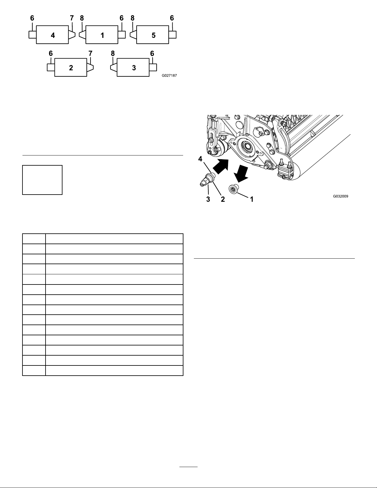
Figure2
Reelmaster7000-D
1.#1cuttingunit5.#5cuttingunit
2.#2cuttingunit
3.#3cuttingunit
4.#4cuttingunit8.Leftrollerbrushdrive
6.Reelmotor
7.Rightrollerbrushdrive
assembly
assembly
2
InstallingtheRollerBrush
Partsneededforthisprocedure:
1Roller-brushhousing
2
Hex-socketbolt(3/8x1inch)
1Roller-brushassembly
1
Shoulderbolt
1
Beltcover/plateassembly(left)
2
Bolt(5/16x1/2inch)
1
Spacer
1Drivepulley
1
Flange-headbolt(3/8x2inches)
1Belt
1
Shimwasher(asrequiredforbeltalignment)
1
Driveshaft(right)
1
Driveshaft(left)
1
Greasetting(90°)
g027187
forRemovingThreadedInserts(page12).
2.Removethecutting-unitthreadedinsertforthe
rear-roller-brushdrive(Figure1andFigure2)
anddiscardit(Figure3).
1.Restrainthereel;refertoRestrainingtheReel
g032009
Figure3
1.Threadedinsert
(left-handedinsertshown)
2.Theleftinserthasagroove
onthefaceoftheinsert
here.
3.Driveshaft
4.Applythread-locking
compoundhere.
Note:Left-handedinsertsareonReelmaster
3100CuttingUnits1and2(Figure1)and
Reelmaster7000CuttingUnits1,3,and5
(Figure2).
3.Restrainthereel;refertoRestrainingtheReel
forInstallingThreadedInserts(page13).
4.Applythread-lockingcompoundtothedriveshaft
threads(Figure3)andinstallthedriveshaft,
torquingitto115to128N∙m(85to95ft-lb).
Note:Theuseofanimpactgunisnotenough
toensureproperinstallation.Failuretoproperly
torquethedriveshaftcanresultintheassembly
unscrewingitselfduringoperation.
PreparingtheMachine
1.Parkthemachineonalevelsurfaceandengage
theparkingbrake.
2.Ensurethatthecuttingunitsaredisengaged.
3.Shutofftheengineandremovethekey .
4.Removeallthecuttingunitsfromthemachine.
3
Page 4

MountingtheRoller-Brush
RepositioningtheIdlerPulley
Housing
1.EnsurethattheO-ringisinstalledonthe
roller-brushhousing(Figure4).
Figure4
1.Roller-brushhousing
2.Mounttheroller-brushhousingtothe
reel-bearinghousingwith2hex-socketbolts(3/8
x1inch);refertoFigure5.
Note:Positiontheroller-brushhousingsothat
thethreadedholeistowardthefrontofthe
cuttingunit.
2.O-ring
Assembly(ForRight-HandDrives
Only)
Note:Right-handdrivesareonReelmaster3100
CuttingUnit3(Figure1)andReelmaster7000Cutting
Units2and4(Figure2).
Forright-handrearrollerbrushdrives(Figure1and
Figure2),reversetheidlerpulleyassemblytomount
ontherightendofthecuttingunit(Figure6)as
follows:
1.Removetheidlerpulleyassemblyfromtheleft
endofthecuttingunitandmountittothelower
holeinthebrushplateontherightendofthe
g009051
cuttingunit(Figure6).
Note:Theidlerpulleymustpivotfreely;donot
overtightenthelocknutontheidlerpivotbolt.
2.Removethecarriageboltandnutandrelocate
themtotheupperholepreviouslyoccupiedby
theidlerpulleyassembly(Figure6).
Note:EnsurethattheO-ringisproperly
positionedintheroller-brushhousing.
Figure5
1.Roller-brushhousing3.Threadedhole
2.Hex-socketbolt
g029307
Figure6
g218674
1.Idlerpulleyinstallationfor
leftendofreel(assupplied
inkit)
2.Idlerpulleyinstallationfor
rightendofreel
3.Carriageboltandnut
4.Donotovertightenthis
locknut.
RemovingtheBrushCoverDrain
Plug
Removeonlythebottomdrainplug(Figure7)from
thebrushcovers.Thisallowsmoisturetodrainfrom
thebeltarea.
4
Page 5

Figure7
1.Brushcover2.Bottomdrainplug
InstallingtheRollerBrush
Assembly
1.Removethegreasettingfortherollerfromthe
sideofthecuttingunitthathastheroller-brush
housing(Figure9).
g009049
1.6mm(1/4inch)spacer3.90°greasetting
2.Side-platemountingange4.Flangelocknuts(remove)
Figure9
g031873
3.Removethe2angelocknutssecuringeach
rollerbrackettothesideplates(Figure9).
Note:Donotremovethebolts.Also,remove
any6mm(1/4inch)spacerspositioned
onthetopsideoftheside-platemounting
ange.
4.Positiontheleftorrightroller-brushassembly
mountingbracketsontotheroller-bracketbolts
(Figure10).
Figure8
1.Greasetting
2.Installthe90°greasettingsothatitfaces
backward(Figure8).
g031872
g193248
Figure10
1.Leftroller-brushassembly
2.Roller-brushmounting
bracket
Important:Mounttheroller-brushassembly
mountingbracketsdirectlytothetopsurface
ofthecutting-unitside-platemounting
ange.Donotputspacersbetweenthe
5
Page 6

roller-brushmountingbracketsandthe
side-platemountinganges.Savethe
additional6mm(1/4inch)spacersfor
potentiallateruse.
5.Securethebrush-assemblymountingbrackets
tothecutting-unitsideplateswiththenuts
previouslyremoved.
InstallingtheRollerBrushPlate
1.Slideeachexcludersealoutwarduntilthelip
sealsareinlightcontactwitheachbearing
housing(Figure11).
g218675
Figure12
Figure11
1.Bearinghousing2.Excluderseal
2.Applyacoatingofgreasetotheinnerdiameter
ofthegrommetintheroller-brushhousing
(Figure12).
1.Bolt
2.Shoulderbolt
3.Grommet
4.Cleanoutanypaint
fromthethreadsusing
a5/16–18tapbefore
screwingintheshoulder
bolt.
5.Roller-brushhousing
6.Roller-brushpivotplate
assembly
3.Installtheleftorrightroller-brushpivotplate
(Figure12).
Note:Whenyouinserttheprotrusiononthe
pivotplateintothegrommetintheroller-brush
housing,ensurethatthegrommetstaysproperly
seatedinthehousing.Theroller-brushpivot
plateisproperlyseatedwhenthereisno
resistancefromtherubbergrommetanditpivots
g027192
freely.
Note:Ensurethattheidler-pulleyassemblyis
installedonthebottomasshowninFigure12.
4.Applythread-lockingcompoundtothe2bolts
(5/16x1/2inch)andusethemtomountthe
brushplatetotheroller-brushbearinghousing
(Figure12).
Note:T orquetheboltsto20to25N∙m(15to
19ft-lb).
5.Cleanoutanypaintfromthethreadsinthe
roller-brushhousing,usinga5/16–18tap,before
screwingintheshoulderbolt(Figure12).
Important:Ifthethreadsarenotcleaned
beforetheshoulderboltisscrewedin,the
boltcouldbreak.
6.Applythread-lockingcompoundtotheshoulder
bolt(Figure12).
7.Securethebrushplatetotheroller-brush
housingwiththeshoulderbolt(Figure12).
Note:T orquetheboltto20to25N∙m(15to
19ft-lb).
6
Page 7

Note:Theshoulderboltshouldnotclampthe
platetothehousing.
8.Checktoensurethattheroller-brushplateis
paralleltothecutting-unitsideplate.Ifitisnot
parallel,proceedasfollows:
A.Loosenthe2angelocknutssecuring
theroller-brushmountingbrackettothe
cutting-unitsideplate(Figure13).
B.Rotatetheroller-brushbearinghousinguntil
thebrushplateisparalleltothecutting-unit
sideplate(Figure13).
C.Tightenthe2angelocknutssecuring
theroller-brushmountingbrackettothe
cutting-unitsideplate(Figure13).
g027303
Figure14
Figure13
1.Loosentheseboltsforpositioningtherollerbrush.
2.Loosenthesenutsformakingtheroller-brushplateparallel.
PositioningtheRollerBrush
1.Loosenthe2boltssecuringeachroller-brush
bearinghousingtotheroller-brushmounting
bracket(Figure13).
Note:Theboltsshouldbeloosefromthe
factory.
2.Positiontherollerbrushsothatitisjusttouching
orrestingontherearroller(Figure14).
Important:Theroller-brushshaftmustnot
contactthecutting-unitsideplate.
Important:Heavybrushcontactonthe
rollerwillcauseprematurebrushwear.
1.Bearinghousing(some
partsnotshown)
2.Sideplate
3.Rollerbrush
4.Ensurethatthereis
clearancehere.
5.Lightcontact
6.Rearroller
7.Greasetting
Note:Theroller-brushshaftmustbeparallel
totherearroller.
g193249
Important:Positionbothroller-brush
bearinghousingssothattheyareparallel
tothegroundtoensureclearanceforthe
rear-rollergreasetting.
3.Tightenthe2boltssecuringeachroller-brush
bearinghousingtotheroller-brushmounting
brackets.
InstallingtheDrivePulley
1.Insertthespacerontotheshaftinthebearing
housing(Figure15).
2.Insertthedrivepulleyintothespacerandonto
thedriveshaft(Figure15).
Note:Ensurethatthepulleytabsarepositioned
intheslotinthedriveshaft.
3.Securethepulleyandspacertothedriveshaft
withaange-headbolt(3/8x2inches);refer
toFigure15.
Note:T orquetheboltto47to54N∙m(35to
40ft-lb).
7
Page 8

Important:Iftheboltisnotproperly
torqued,theboltwillcomeloose.
Figure15
g027195
1.Driveshaft
2.Spacer
3.Drivepulley
4.Flange-headbolt—torque
InstallingtheBelt
1.Installthebeltontothepulleysasfollows:
•Loopthebeltaroundthedrivepulleyand
thenoverthetopoftheidlerpulley(Figure
16).
Figure16
1.Drivepulley3.Belt
2.Idler-pulleyassembly4.Drivenpulley
•Startthebeltonthedrivenpulley(Figure
17).
•Useadeep-wellsocket(9/16inch)torotate
thebrushassemblyandguidethebeltonto
thedrivenpulley(Figure17).
to47to54N∙m(35to40
ft-lb)
g020390
Figure17
1.Belt
2.Deep-wellsocket(9/16
inch)
Important:Ensurethattheribsonthebelt
areproperlyseatedinthegroovesineach
pulleyandthatthebeltisinthecenterofthe
idlerpulley .
2.Pushdownontheidlerpulleytoensurethatthe
idler-pulleyassemblypivotsfreely.
CompletingtheInstallation
1.Checkthealignmentofthebeltandpulleysas
follows:
•Thebeltmustbeproperlytensioned
(installed)priortocheckingthealignment.
•Layastraightedgealongtheouterfaceof
thedrivepulley(Figure18).Donotlaythe
g027196
straightedgeacrossboththedrivepulleyand
thedrivenpulley .
•Theouterfacesofthedrivepulleyandthe
drivenpulleyshouldbeinlinewithin0.76
mm(0.030inch).
•Ifthepulleysarenotaligned,referto
CheckingthePulleyAlignment(page1 1).
•Ifthepulleysarealigned,continuewiththe
installation.
•Donotusetheidlerpulleytocheckthe
alignment.
Important:Thebeltmayfailprematurely
ifthepulleysarenotproperlyaligned.
8
Page 9

Figure18
2.Slidethebeltcoverontothemountingboltsand
securethecoverwith2angenuts(Figure19).
Important:Donotovertightenthenutsas
damagetothecovermayoccur.
g027197
Figure20
g031843
3
InstallingtheHigh
Height-of-CutBrush
(Optional)
(Optional)
Partsneededforthisprocedure:
—
Highheight-of-cutbrush(optional)
Figure19
1.Beltcover
2.Setscrewinstalled
3.Setscrewremoved
3.Lubricatethegreasettingsoneachofthe
roller-brushbearinghousingswithNo.2lithium
grease(Figure20).Wipeoffanyexcessgrease,
especiallyaroundtheexcluderseals.
g027198
Procedure
Installthehighheight-of-cutbrush(soldseparately)
whentheheightofcutis2.5cm(1inch)ormore(5or
morespacersinstalledbelowthesideplatepad).
1.Ifarollerbrushisinstalledonthecutting
unit,removethe2bolts,washers,andnuts
securingthenon-drivebearinghousingtothe
bearing-housingmountingbracket(Figure21
andFigure22).
g027200
Figure21
1.Non-drivebearinghousing
9
Page 10

2.Slidethenon-drivebearinghousingandthe
excludersealoffthebrushshaft(Figure22).
Figure22
g027201
1.Non-drivebearinghousing
2.Excluderseal
3.Brushshaft
3.Removethe2J-boltsandthenuts(Figure23).
4.Slidetheexistingbrushoffthebrushshaft
(Figure23).
5.Loosenthe2bolts,washers,andnutssecuring
thedrive-bearinghousingtothebearing-housing
mountingbracket(Figure23).
6.Slidethehighheight-of-cutbrushontothebrush
shaft(Figure23).
7.Clampthebrushontotheshaftwiththe2J-bolts
andnutspreviouslyremoved(Figure23).
Important:Insertthethreadedendofthe
J-boltsthroughtheouterholesofthebrush
shaftwhilehookingthecurvedendsofthe
J-boltsintotheinnerholes.
8.TorquetheJ-boltlocknutsto2to3N∙m(20to
25in-lb).
Figure23
1.Highheight-of-cutbrush
2.J-bolts
3.Loosenthesebolts.
9.Installtheexcludersealandthenon-drive
bearinghousingontothebrushshaft(Figure22).
10.Mountthenon-drivebearinghousingtothe
bearing-housingmountingbracketwiththe2
bolts,washers,andnutspreviouslyremoved.
Note:Becarefulnottoknockthesealspring
off.
11.Tightenthe2bolts,washers,andnutssecuring
thedrive-bearinghousingtothebearing-housing
mountingbracket.
g027202
10
Page 11

Maintenance
5.Ifthepulleyneedstomoveout,adda0.8mm
(0.032inch)thickwasher(Figure25).
•Ensurethatthebrushisparalleltotherollerwith
1.5mm(0.060inch)clearancetolightcontact.
•Greasethettingsevery50hoursandafterevery
washing.
•Whenreplacingarollerbrush,torquetheJ-bolts
to2to3N∙m(20to25in-lb).
•Whenreplacingthebrush-shaft-drivenpulley,
torquethenutto36to45N∙m(27to33ft-lb).
•Whenreplacingthebrush-drivepulley,apply
removablethread-lockingcompoundandtorque
theboltto47to54N∙m(35to40ft-lb).
Note:Therollerbrush,theidlerbearing,andthebelt
areconsideredconsumableitems.
CheckingthePulley
Alignment
1.Makenoteofwhichwaythepulleyneedsto
move.
Note:Thedrivenpulley(attheroller-brush
shaft)canmoveinorout(Figure24).
Note:Ifthepulleyneedstomovein,remove
theexisting0.8mm(0.032inch)thickwasher.
6.Installthedrivenpulley .
Figure25
1.Locknut
2.Drivenpulley
7.Whileholdingthebrush-shaftats,securethe
drivenpulleyontheshaftwiththeangenut
(3/8–16inch)previouslyremoved.
3.Washer—0.8mm(0.032
inch)thick
4.Brush-shaftats
g009077
Figure24
1.Drivenpulley3.Driven-pulleynut
2.Idlerpulleyassembly
2.Whilerotatingthereel,whichrotatesthedrive
pulley,prythebeltoffthedrivepulley(Figure24)
Note:Wearapaddedgloveoruseaheavyrag
torotatethereel.
3.Removethelocknutsecuringthedrivenpulley
tothebrushshaft(Figure24orFigure25).
Note:Usea1/2inchwrenchontheroller-brush
shaftatstokeepitfromrotating.
4.Removethedrivenpulleyfromtheshaft(Figure
25).
Note:Seatthelocknut;thentorqueitto36to
45N∙m(27to33ft-lb).
8.Installthebeltontothepulleysasfollows:
A.Loopthebeltaroundthedrivepulleyand
thenoverthetopoftheidlerpulley(Figure
26).
g020303
g031875
Figure26
1.Drivenpulley3.Drivepulley
2.Idler-pulleyassembly4.Belt
B.Startthebeltonthedrivenpulley(Figure
26).
C.Useadeep-wellsocket(9/16inch)torotate
thebrushassemblyandguidethebeltonto
thedrivenpulley(Figure27).
11
Page 12

Figure27
1.Belt
2.Deep-wellsocket(9/16
inch)
Important:Ensurethattheribsonthebelt
areproperlyseatedinthegroovesineach
pulleyandthatthebeltisinthecenterofthe
idlerpulley .
9.Checkthepulleyalignmentagainandrepeat
thisprocedureifnecessary.
RestrainingtheReel
WARNING
Thecuttingreelbladesaresharpandcapable
ofamputatinghandsandfeet.
•Keepyourhandsandfeetoutsideofthe
reel.
•Ensurethatthereelisrestrainedbefore
servicingit.
RestrainingtheReelforRemoving
ThreadedInserts
1.Loosentheshield-boltontheleftsideofthe
cuttingunitandraisetherearshield(Figure28).
2.Insertalong-handledprybar(recommended
3/8"x12"withscrewdriverhandle)throughthe
backofthecuttingreel,closesttothesideofthe
g020390
cuttingunitthatyouwillbetorquing(Figure28).
3.Placetheprybaragainsttheweldsideofthe
reelsupportplate(Figure28).
Note:Inserttheprybarbetweenthetopofthe
reelshaftandthebacksof2reelbladessothat
thereelwillnotmove.
Important:Donotcontactthecuttingedge
ofanybladeswiththeprybar;thismay
damagethecuttingedgeand/orcauseahigh
blade.
Important:Theinsertontheleftsideof
thecuttingunithasleft-handthreads.The
insertontherightsideofthecuttingunithas
right-handthreads.
12
Page 13

Figure28
1.Threadedinsertfor
removal
2.Loosentheshieldbolt.5.Reelsupportplate
3.Rearshield6.Prybarinsertedalong
4.Reelshaft
theweldsideofthereel
supportplate.
RestrainingtheReelforInstalling
ThreadedInserts
1.Insertalong-handledprybar(recommended
3/8"x12"withscrewdriverhandle)throughthe
frontofthecuttingreel,closesttothesideofthe
cuttingunitthatyouwillbetorquing(Figure29).
2.Placetheprybaragainsttheweldsideofthe
internalcuttingreelreinforcement(Figure29).
Note:Theprybarshouldcontactabladeatthe
front,thereelshaft,andabladeatthebackof
thebackofthereel,lockingitinplace.
Important:Donotcontactthecuttingedge
ofanybladeswiththeprybar;thismay
damagethecuttingedgeand/orcauseahigh
g280383
blade.
Important:Theinsertontheleftsideof
thecuttingunithasleft-handthreads.The
insertontherightsideofthecuttingunithas
right-handthreads.
4.Restthehandleoftheprybaragainsttherear
roller.
5.Completetheremovalofthethreadedinsert
whileensuringthattheprybarstaysinplace,
thenremovetheprybar.
6.Lowertherearshieldandtightentheshield-bolt.
Figure29
1.Threadedinsertfor
installation
2.Reelshaft
3.Weldsideofsupportplate
4.Prybar
3.Restthehandleoftheprybaragainsttheroller
g280384
4.Pertheinsert’sinstallationinstructionsand
torquerequirements,completetheinstallationof
thethreadedinsertwhileensuringthatthepry
barstaysinplace,thenremovetheprybar.
13
Page 14

Notes:
Page 15

DeclarationofIncorporation
TheToroCompany,8111LyndaleAve.South,Bloomington,MN,USAdeclaresthatthefollowingunit(s)
conform(s)tothedirectiveslisted,wheninstalledinaccordancewiththeaccompanyinginstructionsontocertain
ToromodelsasindicatedontherelevantDeclarationsofConformity.
ModelNo.
SerialNo.
03243
03246
—
—
ProductDescriptionInvoiceDescription
27-inchRearRollerBrushKit
32-inchRearRollerBrushKit
27INRRBONL YKIT
32INRRBONLYKIT
GeneralDescription
27inRRB
32inRRB
Directive
2006/42/EC
2006/42/EC
RelevanttechnicaldocumentationhasbeencompiledasrequiredperPartBofAnnexVIIof2006/42/EC.
Wewillundertaketotransmit,inresponsetorequestsbynationalauthorities,relevantinformationonthispartly
completedmachinery.Themethodoftransmissionshallbeelectronictransmittal.
ThismachineryshallnotbeputintoserviceuntilincorporatedintoapprovedT oromodelsasindicatedonthe
associatedDeclarationofConformityandinaccordancewithallinstructions,wherebyitcanbedeclaredin
conformitywithallrelevantDirectives.
Certied:
JohnHeckel
Sr.EngineeringManager
811 1LyndaleAve.South
Bloomington,MN55420,USA
January24,2019
AuthorizedRepresentative:
MarcelDutrieux
ManagerEuropeanProductIntegrity
ToroEuropeNV
Nijverheidsstraat5
2260Oevel
Belgium
Page 16

 Loading...