

Page 1

Reelmaster 2300/2600-D
Traction Unit
Model No. 03422—210000001 and Up
Model No. 03422TE—210000001 and Up
Model No. 03247—210000001 and Up
Model No. 03427TE—210000001 and Up
Model No. 03471
Model No. 03472
Form No. 3326-466
Operator’s Manual
English (EN)
Page 2

Warning
The engine exhaust from this product contains
chemicals known to the State of California to cause
cancer, birth defects, or other reproductive harm.
Contents
Introduction 2. . . . . . . . . . . . . . . . . . . . . . . . . . . . . . . . .
Safety 3. . . . . . . . . . . . . . . . . . . . . . . . . . . . . . . . . . . . . .
Safe Operating Practices 3. . . . . . . . . . . . . . . . . . . .
Toro Mower Safety 4. . . . . . . . . . . . . . . . . . . . . . . .
Sound Pressure Level 5. . . . . . . . . . . . . . . . . . . . . . .
Vibration Level 5. . . . . . . . . . . . . . . . . . . . . . . . . . . .
Safety and Instruction Decals 6. . . . . . . . . . . . . . . . .
Slope Chart 9. . . . . . . . . . . . . . . . . . . . . . . . . . . . . . .
Specifications 11. . . . . . . . . . . . . . . . . . . . . . . . . . . . . . . .
General Specifications 11. . . . . . . . . . . . . . . . . . . . .
Measurements 12. . . . . . . . . . . . . . . . . . . . . . . . . . . .
Optional Equipment 12. . . . . . . . . . . . . . . . . . . . . . . .
Setup 12. . . . . . . . . . . . . . . . . . . . . . . . . . . . . . . . . . . . . .
Loose Parts 12. . . . . . . . . . . . . . . . . . . . . . . . . . . . . . .
Installing the Rear Wheel 14. . . . . . . . . . . . . . . . . . . .
Installing the Seat 14. . . . . . . . . . . . . . . . . . . . . . . . . .
Adjusting the Rear Carrier Frame Height 15. . . . . . .
Mounting the Carrier Frames to the Cutting Units 15
Installing the Front Lift Arms 15. . . . . . . . . . . . . . . .
Mounting the Cutting Unit Drive Motors 16. . . . . . .
Mounting the Cutting Units 17. . . . . . . . . . . . . . . . . .
Installing the Counterbalance Springs 17. . . . . . . . . .
Adding Rear Ballast 19. . . . . . . . . . . . . . . . . . . . . . . .
Affixing the Decals 20. . . . . . . . . . . . . . . . . . . . . . . .
Activating and Charging the Battery 20. . . . . . . . . . .
Before Operating 21. . . . . . . . . . . . . . . . . . . . . . . . . . . . .
Checking the Crankcase Oil 21. . . . . . . . . . . . . . . . . .
Filling the Fuel Tank 21. . . . . . . . . . . . . . . . . . . . . . .
Checking the Cooling System 22. . . . . . . . . . . . . . . .
Checking the Hydraulic System Fluid 22. . . . . . . . . .
Inspecting the Fuel Filter 23. . . . . . . . . . . . . . . . . . . .
Checking the Tire Pressure 24. . . . . . . . . . . . . . . . . .
Checking the Reel to Bedknife Contact 24. . . . . . . . .
Checking the Torque of the Wheel Nuts 24. . . . . . . .
Operation 24. . . . . . . . . . . . . . . . . . . . . . . . . . . . . . . . . . .
Controls 24. . . . . . . . . . . . . . . . . . . . . . . . . . . . . . . . .
Starting and Stopping the Engine 27. . . . . . . . . . . . . .
Bleeding the Fuel System 27. . . . . . . . . . . . . . . . . . . .
Checking the Operation of the Interlock Switches 28
Page
Page
Towing the Traction Unit 28. . . . . . . . . . . . . . . . . . . .
Operating Characteristics 29. . . . . . . . . . . . . . . . . . . .
Selecting the Clip Rate (Reel Speed) 29. . . . . . . . . . .
Training Period 30. . . . . . . . . . . . . . . . . . . . . . . . . . . .
Before Mowing 30. . . . . . . . . . . . . . . . . . . . . . . . . . .
Transport Operation 30. . . . . . . . . . . . . . . . . . . . . . . .
Inspection and Clean-Up After Mowing 30. . . . . . . .
Maintenance 31. . . . . . . . . . . . . . . . . . . . . . . . . . . . . . . . .
Recommended Maintenance Schedule 31. . . . . . . . .
Daily Maintenance Checklist 32. . . . . . . . . . . . . . . . .
Service Interval Chart 33. . . . . . . . . . . . . . . . . . . . . .
Greasing the Bearings and Bushings 33. . . . . . . . . . .
Removing the Hood 35. . . . . . . . . . . . . . . . . . . . . . . .
General Air Cleaner Maintenance 35. . . . . . . . . . . . .
Cleaning the Radiator and Screen 36. . . . . . . . . . . . .
Changing the Engine Oil and Filter 36. . . . . . . . . . . .
Changing the Hydraulic System Fluid and Filter 36. .
Hydraulic System Test Ports 37. . . . . . . . . . . . . . . . .
Replacing the Fuel Filter 37. . . . . . . . . . . . . . . . . . . .
Adjusting the Transmission for Neutral 38. . . . . . . . .
Adjusting the Belts 39. . . . . . . . . . . . . . . . . . . . . . . . .
Adjusting the Traction Pedal 39. . . . . . . . . . . . . . . . .
Adjusting the Traction Pedal Damper 40. . . . . . . . . .
Adjusting the Hand Brake 40. . . . . . . . . . . . . . . . . . .
Battery Care 40. . . . . . . . . . . . . . . . . . . . . . . . . . . . . .
Storing the Battery 41. . . . . . . . . . . . . . . . . . . . . . . . .
Fuses 41. . . . . . . . . . . . . . . . . . . . . . . . . . . . . . . . . . . .
Backlapping 41. . . . . . . . . . . . . . . . . . . . . . . . . . . . . .
Electrical Schematic 43. . . . . . . . . . . . . . . . . . . . . . . .
Hydraulic Schematic (Model No. 03422—2WD) 44.
Hydraulic Schematic (Model No. 03427—3WD) 45.
California Emission Control System Warranty
Statement 49. . . . . . . . . . . . . . . . . . . . . . . . . . . . . . .
The Toro General Commercial Products Warranty 52. . .
Introduction
Read this manual carefully to learn how to operate and
maintain your product properly. The information in this
manual can help you and others avoid injury and product
damage. Although Toro designs and produces safe
products, you are responsible for operating the product
properly and safely.
Whenever you need service, genuine Toro parts, or
additional information, contact an Authorized Service
Dealer or Toro Customer Service and have the model and
serial numbers of your product ready. The two numbers are
stamped into a plate that is riveted to the frame at the rear
of the mower.
2001 by The Toro Company
8111 Lyndale Avenue South
Bloomington, MN 55420-1196
All Rights Reserved
Printed in the USA
2
Page 3

Write the product model and serial numbers in the space
below:
Model No.
Safe Operating Practices
The following instructions are from ANSI standard
B71.4—1990.
Serial No.
This manual identifies potential hazards and has special
safety messages that help you and others avoid personal
injury and even death. Danger, Warning, and Caution are
signal words used to identify the level of hazard. However,
regardless of the hazard, be extremely careful.
Danger signals an extreme hazard that will cause serious
injury or death if you do not follow the recommended
precautions.
Warning signals a hazard that may cause serious injury or
death if you do not follow the recommended precautions.
Caution signals a hazard that may cause minor or moderate
injury if you do not follow the recommended precautions.
This manual uses two other words to highlight information.
Important calls attention to special mechanical
information and Note: emphasizes general information
worthy of special attention.
Safety
Training
• Read the Operator’s Manual and other training material.
If the operator(s) or mechanic(s) can not read English it
is the owner’s responsibility to explain this material to
them.
• Become familiar with the safe operation of the
equipment, operator controls, and safety signs.
• All operators and mechanics should be trained. The
owner is responsible for training the users.
• Never let children or untrained people operate or
service the equipment. Local regulations may restrict
the age of the operator.
• The owner/user can prevent and is responsible for
accidents or injuries occurring to himself or herself,
other people or property.
Preparation
• Evaluate the terrain to determine what accessories and
attachments are needed to properly and safely perform
the job. Only use accessories and attachments approved
by the manufacturer.
This machine meets or exceeds the B71.4 1990
specifications of the American National Standards
Institute, in effect at time of production, when ballast is
installed according to the chart on page 19.
Note: The addition of attachments made by other
manufacturers that do not meet American National
Standards Institute certification will cause noncompliance
of this machine.
Improper use or maintenance by the operator or owner
can result in injury. To reduce the potential for injury,
comply with these safety instructions and always pay
attention to the safety alert
CAUTION, WARNING, or DANGER—“personal
safety instruction.” Failure to comply with the
instruction may result in personal injury or death.
symbol, which means
• Wear appropriate clothing including hard hat, safety
glasses and ear protection. Long hair, loose clothing or
jewelry may get tangled in moving parts.
• Inspect the area where the equipment is to be used and
remove all objects such as rocks, toys and wire which
can be thrown by the machine.
• Use extra care when handling gasoline and other fuels.
They are flammable and vapors are explosive.
– Use only an approved container.
– Never remove gas cap or add fuel with engine
running. Allow engine to cool before refueling. Do
not smoke.
– Never refuel or drain the machine indoors.
• Check that operator’s presence controls, safety switches
and shields are attached and functioning properly. Do
not operate unless they are functioning properly.
Operation
• Never run an engine in an enclosed area.
• Only operate in good light, keeping away from holes
and hidden hazards.
3
Page 4

• Be sure all drives are in neutral and parking brake is
engaged before starting engine. Only start engine from
the operator’s position. Use seat belts if provided.
• Slow down and use extra care on hillsides. Be sure to
travel in the recommended direction on hillsides. Turf
conditions can affect the machine’s stability. Use
caution while operating near drop-offs.
• Slow down and use caution when making turns and
when changing directions on slopes.
• Never operate with guards not securely in place. Be
sure all interlocks are attached, adjusted properly, and
functioning property.
• Do not change the engine governor setting or overspeed
the engine.
• Stop on level ground, disengage drives, engage parking
brake (if provided), shut off engine before leaving the
operator’s position for any reason including emptying
the grass baskets.
• Stop equipment and inspect the machine after striking
objects or if an abnormal vibration occurs. Make
necessary repairs before resuming operations.
• Keep hands and feet away from the cutting units.
• Look behind and down before backing up to be sure of
a clear path.
• Never carry passengers and keep pets and bystanders
away.
• Slow down and use caution when making turns and
crossing roads and sidewalks. Stop reels if not mowing.
• Do not operate the mower under the influence of
alcohol or drugs.
• Use jack stands to support components when required.
• Carefully release pressure from components with stored
energy.
• Disconnect battery and remove spark plug wire before
making any repairs. Disconnect the negative terminal
first and the positive last. Reconnect positive first and
negative last.
• Use care when checking the reels. Wear gloves and use
caution when servicing them.
• Keep hands and feet away from moving parts. If
possible, do not make adjustments with the engine
running.
• Charge batteries in an open well ventilated area, away
from spark and flames. Unplug charger before
connecting or disconnecting from battery. Wear
protective clothing and use insulated tools.
• Keep all parts in good working condition and all
hardware and hydraulic fittings tightened. Replace all
worn or damaged decals.
Toro Mower Safety
The following list contains safety information specific to
Toro products or other safety information that you must
know that is not included in the ANSI standards.
This product is capable of amputating hands and feet and
throwing objects. Always follow all safety instructions to
avoid serious injury or death.
Use of this product for purposes other than its intended use
could prove dangerous to user and bystanders.
• Use care when loading or unloading the machine into a
trailer or truck.
• Use care when approaching blind corners, shrubs, trees,
or other objects that may obscure vision.
Maintenance and Storage
• Disengage drives, raise the cutting units, set parking
brake, stop engine and remove key and disconnect spark
plug wire. Wait for all movement to stop before
adjusting, cleaning or repairing.
• Clean grass and debris from cutting units, drives,
mufflers, and engine to help prevent fires. Clean up oil
or fuel spillage.
• Let engine cool before storing and do not store near
flame.
• Shut off fuel while storing or transporting. Do not store
fuel near flames or drain indoors.
• Park machine on level ground. Never allow untrained
personnel to service machine.
Preparation
• Always use the proper amount of rear ballast as
specified in this manual.
• Always wear substantial shoes. Do not operate the
machine while wearing sandals, tennis shoes, or
sneakers.
• Wearing safety shoes and long pants is advisable and
required by some local ordinances and insurance
regulations.
• Only fill the fuel tank to within 1 inch of the top of the
tank, not the filler neck. Do not overfill.
• Handle fuel carefully. Wipe up any spills.
4
Page 5

Operation
• Know how to stop the machine and engine quickly.
• Check the safety interlock switches daily for proper
operation. If a switch should fail, replace the switch
before operating the machine. After every two years,
replace all interlock switches in the safety system,
regardless if they are working properly or not.
• Before starting the engine, engage the parking brake,
put the traction pedal in neutral, and the reel drive is
disengaged.
• Using the machine demands attention. To prevent loss
of control:
– Do not drive close to sand traps, ditches, creeks,
steep hillsides, or other hazards.
– Reduce speed when making sharp turns. Avoid
sudden stops and starts.
• Do not touch the engine, muffler, exhaust pipe, or
hydraulic tank while the engine is running or soon after
it has stopped because these areas could be hot enough
to cause burns.
• If a cutting unit strikes a solid object or vibrates
abnormally, stop immediately, turn the engine off, wait
for all motion to stop, and inspect the machine for
damage. A damaged reel or bedknife must be repaired
or replaced before operation is continued.
leaks. Hydraulic fluid escaping under pressure can have
sufficient force to penetrate the skin and cause serious
injury.
• Before disconnecting or performing any work on the
hydraulic system, all pressure in the system must be
relieved by stopping the engine and lowering the cutting
units to the ground.
• If the engine must be running to perform a maintenance
adjustment, keep hands, feet, clothing, and any parts of
the body away from the cutting units, attachments, and
any moving parts. Keep everyone away.
• Do not overspeed the engine by changing governor
settings. To ensure safety and accuracy, have an
Authorized Toro Distributor check the maximum engine
speed.
• The engine must be shut off before checking the oil or
adding oil to the crankcase.
• If major repairs are ever needed or if assistance is
desired, contact an Authorized Toro Distributor.
• To make sure of optimum performance and continued
safety certification of the machine, use only genuine
Toro replacement parts and accessories. Replacement
parts and accessories made by other manufacturers
could be dangerous, and such use could void the
product warranty.
• Before getting off of the seat, move the traction pedal to
neutral, set the parking brake, disengage the cutting
units, and wait for the reels to stop. Stop the engine and
remove the key from the ignition switch.
• Hills over 15 degrees should be mowed up and down,
not side to side.
• Mowing hills may be dangerous. Hills over 20 degrees
generally should not be mowed unless special
safeguards, skills, and conditions exist.
• For steering control, the cutting units must be lowered
when going down slopes.
• Use the reverse pedal for braking.
• Watch out for traffic when near or crossing roads.
Always yield the right of way.
• Raise the cutting units when driving from one work
area to another.
Maintenance and Storage
• Make sure all hydraulic line connectors are tight and all
hydraulic hoses and lines are in good condition before
applying pressure to the system.
Sound Pressure Level
This unit has an equivalent continuous A-weighted sound
pressure at the operator ear of: 85 dB(A), based on
measurements of identical machines per procedures
outlined in Directive 84/538/EEC and amendments.
Vibration Level
This unit has a maximum hand-arm vibration level of
5.5 m/s2 and whole body vibration level of 0.5 m/s2, based
on measurements of identical machines per EN 1033 and
EN 1032.
• Keep your body and hands away from pin hole leaks or
nozzles that eject hydraulic fluid under high pressure.
Use paper or cardboard, not your hands, to search for
5
Page 6
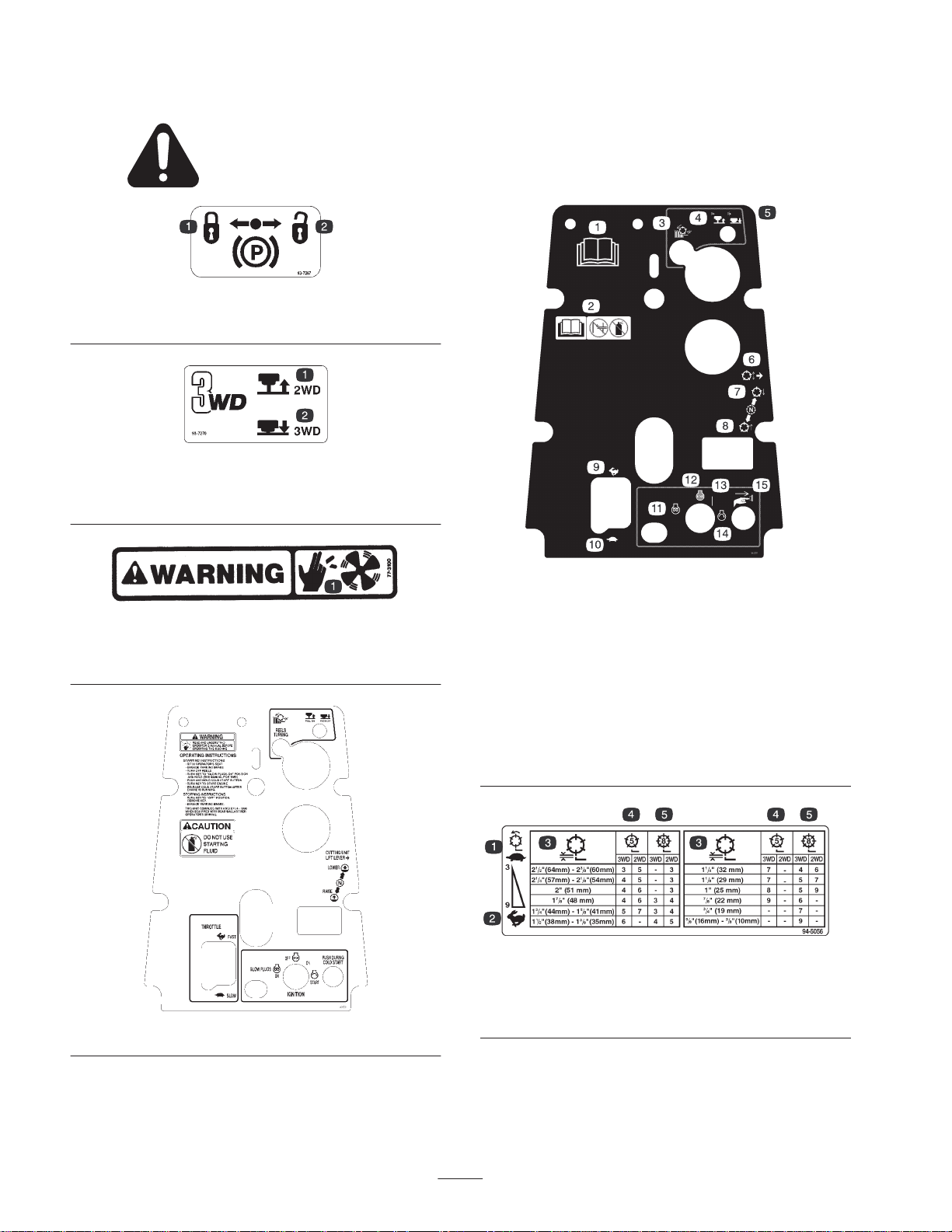
Safety and Instruction Decals
Safety decals and instructions are easily visible to the operator and are located near any area
of potential danger. Replace any decal that is damaged or lost.
93-7267
1. Lock parking brake 2. Unlock parking brake
93-7270
1. Pull out for two wheel
drive.
2. Push in for three wheel
drive.
77-3100
1. Cutting/dismemberment hazard—stay away from rotating fan
blade.
94-4985 (Model No. 03422 and 03427)
94-3351 (Model No. 03427TE)
1. Read the operator’s
manual.
2. Do not use starting
fluid—read the operator’s
manual for further
instructions.
3. Reels turning.
4. Pull out to turn cutting
units on.
5. Push to turn cutting units
off.
1. Slow reel speed
2. Fast reel speed
3. Reel height
6. Cutting unit lift lever
7. Lower cutting units
8. Raise cutting units
9. Throttle fast
10. Throttle slow
11. Glow plugs on
12. Engine off
13. Engine on
14. Engine start
15. Push during cold start.
94-5056
4. 5 Blade cutting unit
5. 8 Blade cutting unit
6
Page 7
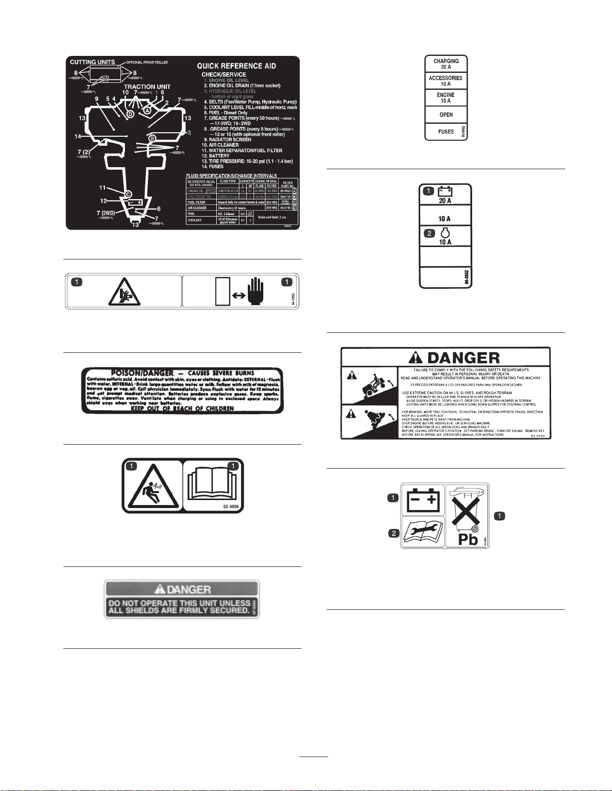
104-3885 (Model No. 03422 and 03427)
94-3353
1. Crushing of fingers or hands—stay a safe distance away.
26-7390
93-6902 (Model No. 03422 and 03427)
94–3352 (Model No. 03427TE)
1. Battery 2. Engine
93-6696
1. Warning—spring loaded mechanism. Read the operator’s
manual.
67-5360
1. The battery contains lead.
Do not dispose of in the
garbage.
83-9550
93-6668
2. Read the operator’s
manual before performing
any maintenance.
7
Page 8
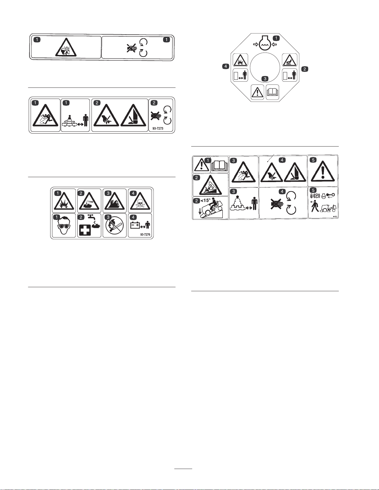
93-7272
1. Cutting/dismemberment hazard—stay away from moving parts.
93-7273
1. Thrown object
hazard—keep bystanders
away.
2. Cutting/dismemberment
hazard of hands or
feet—stay away from
moving parts.
93-7276
1. Explosion hazard—wear eye protection.
2. Caustic liquid hazard—flush skin with water.
3. Fire hazard—sparks, flame, and smoking prohibited.
4. Poison—keep children away from the battery.
93-7840
1. Engine coolant under
pressure
2. Hot surface—stay away.
3. Warning—read the
operator’s manual.
4. Explosion hazard—stay
away.
93-7271
1. Warning—read the operator’s manual.
2. Tipping hazard—when driving down slopes less than 15
degrees, lower the cutting units to the ground.
3. Thrown object hazard—keep bystanders away.
4. Cutting/dismemberment hazard of hand or feet—stay away
from rotating blades and moving parts.
5. Warning—before leaving the operator’s seat, set the parking
brake, stop the engine, and remove the ignition key.
8
Page 9
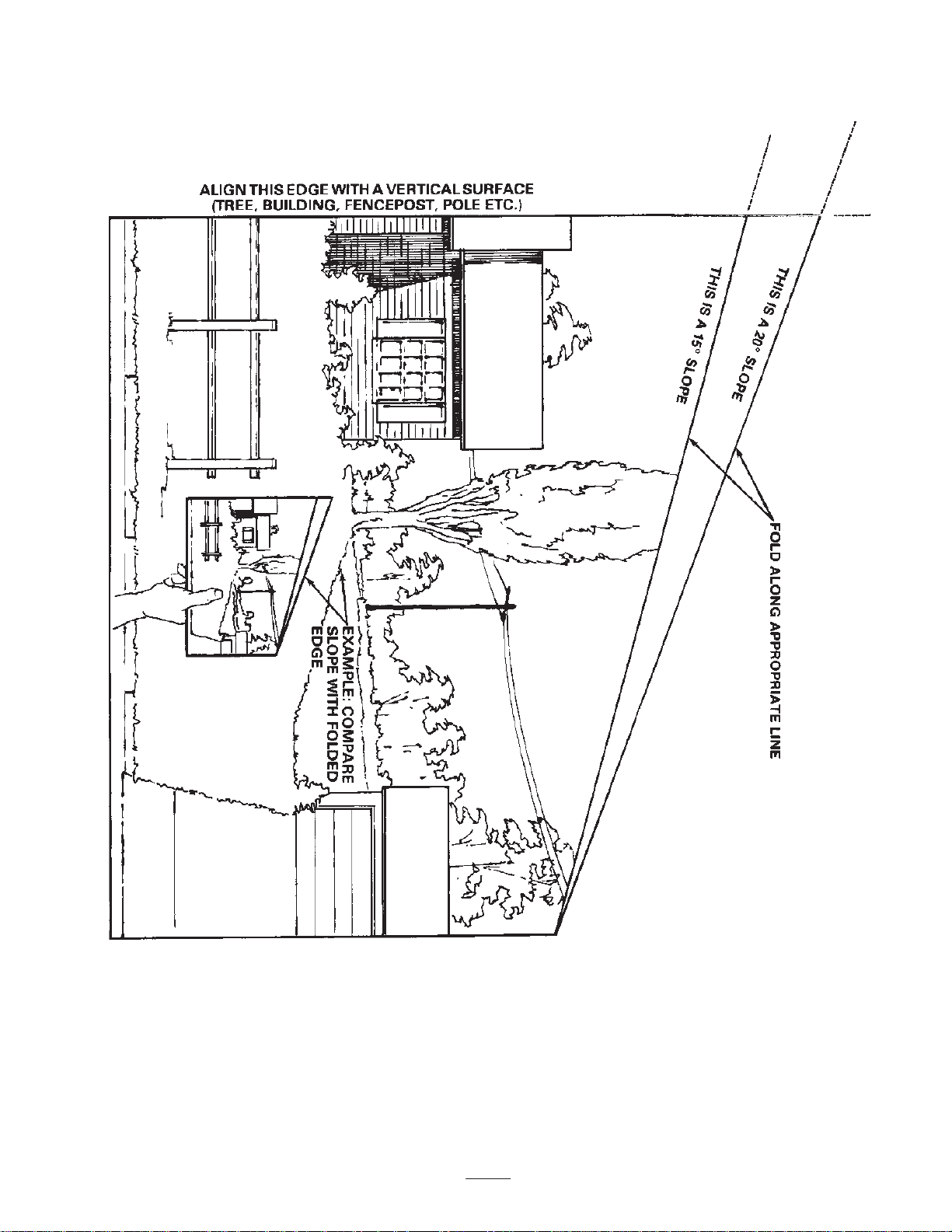
Slope Chart
9
Page 10

10
Page 11

Specifications
Note: Specifications and design subject to change without notice.
General Specifications
Perkins, 4-cycle, 3-cylinder, liquid cooled, vertical OHV, diesel engine with
centrifugal water pump. 18 hp (13.4 kW); governed to a maximum speed of 3200
Engine
Radiator Side mounted industrial radiator, 7 fins per inch. Approx. 5 quart (4.7 liter) capacity.
Electrical
Fuel Capacity 6.5 gallons
Traction Drive
RPM. 41.2 cu. in. (676 cc) displacement. Forced lubrication gear pump. Mechanical
centrifugal governor. Mechanical fuel transfer pump. Fuel filter/water separator with
replaceable filter element. 12 volt (0.7 kW) starter. Heavy duty remote mounted air
cleaner spin-on oil filter.
12 volt Group 55, 450 cold cranking amps at 0°F (–18°C) ,75 minute reserve
capacity at 80°F (27°C). 14 amp alternator with regulator/rectifier. Seat switch,
PTO, and traction interlock switches. Indicator light when cutting units are running.
High torque hydraulic wheel motors. 3-wheel drive; two position selector valve
located below seat, push for 3-wheel drive and pull for 2-wheel drive. Oil cooler and
shuttle valve provide positive closed-loop cooling.
Hydraulic Oil
Capacity/Filter
Ground Speed
Tires/Wheels
Frame
Steering Pinion and sector gear with solid drag link to rear steer wheel arm
Brakes
Controls
Remote mounted, 2.3 gallon (8.7 liter) oil reservoir. 25 micron remote mounted spin
on filter.
Infinitely variable speed selection in forward and reverse
Mowing speed: 0–5 mph (0–8 km/h)
Transport speed: 0–8 mph (0–13 km/h)
Reverse speed: 0–3 mph (0–4.8 km/h).
Two front traction drive tires, 20 x 10-8 tubeless, 4-ply rating. Rear steering tire and
tube; 20 x 8-8, 4-ply rating. Demountable front rims. Recommended tire pressure:
16–20 psi front and rear tires.
Frame consists of formed steel, welded steel, and steel tubing components.
Model 03422: Tricycle vehicle with 2-wheel traction drive and rear wheel steering
Model 03427: Tricycle vehicle with 3-wheel traction drive and rear wheel steering
Service braking accomplished through dynamic characteristics of hydrostat.
Parking or emergency brake is actuated by ratchet hand lever on the operator’s
left-hand side.
Foot operated traction pedal and traction pedal stop. Hand operated throttle,
ignition switch, reel engagement switch, cold start button reel unit lift lever, parking
brake, and seat adjustment.
Model 03427 only: 2 position selector valve for 2 or 3-wheel drive selection.
Gauges and Protective
Systems
Seat
Cutting Unit Lift
Hour meter, temperature gauge. 4 light warning cluster gauge: oil pressure, water
temperature, amps, and glow plug. High water temperature shutdown. Electric
traction pump declutching switch for cold start. Engine preheat incorporated into
ignition switch.
Adjustable to operator weight, fore and aft, w/removeable foldup armrests
Hydraulic lift with automatic reel shutoff
11
Page 12

Measurements
Optional Equipment
Wheel tread width 54-1/2 in. (138 cm)
Wheel base 55 in. (140 cm)
Width 76-1/2 in. (194 cm)
Transport width
RM 2300-D
RM 2600-D
Length
Height
Weight
Model 03422—2WD
without cutting units
Model 03427—3WD
without cutting units
Model 03461—27″ 5
blade cutting unit
Model 03462—27″ 8
blade cutting unit
Model 03466—32″ 5
blade cutting unit
Model 03467—32″ 8
blade cutting unit
72 in. (183 cm)
85 in. (216 cm)
1066 lb. (484 kg)
1096 lb. (497 kg)
136 lb. (62 kg)
143 lb. (65 kg)
158 lb. (72 kg)
167 lb. (76 kg)
Cushion Seat Model No. 30796
Deluxe Seat w/Suspension Model No. 30797
Armrest Kit for Model No. 30796 Model No. 30707
Seat Weight Kit
(for Seat Model No. 30796 Only)
3WD Rear Weight Kit Part No. 94-3663
Rear Weight Kit Part No. 83-9370
Rear Weight Part No. 83-9390
Part No. 80-4210
RM 2300-D Optional Equipment
5 Blade Cutting Unit Model No. 03461
8 Blade Cutting Unit Model No. 03462
2WD Weight Kit (Baskets) Part No. 94-5974
RM 2600-D Optional Equipment
5 Blade Cutting Unit Model No. 03466
8 Blade Cutting Unit Model No. 03467
Setup
Note: Determine the left and right sides of the machine from the normal operating position.
Loose Parts
Note: Use this chart as a checklist to ensure that all parts necessary for assembly have been received. Without these parts,
total setup cannot be completed. Some parts may have already been assembled at the factory.
Description
Wheel assembly
Flat washer
Axle
Locknut
Wheel assembly
Lub nut
Flat washer
Capscrew
Locknut
Qty. Use
1
2
1
1
1
4
3
3
3
Installing the rear wheel on Model No. 03422
Installing the rear wheel on Model No. 03427
Mounting the carrier frames to the cutting units.
12
Page 13

Description UseQty.
Lift arm
Pivot rod
Capscrew, 5/16 x 7/8 in.
Lock washer
Lift chain
Clevis pin
Cotter pin
Thrust washer
Flat washer
Flange head capscrew
Spring
Vinyl sleeve
Spring shackle
Clevis pin
Cotter pin
Shackle
Spring anchor
Capscrew, 1/4 x 3/4 in.
Locknut
2
2
2
2
2
4
4
3
3
3
3
1
3
6
6
2
2
4
4
Installing the from lift arms (supplied with the
Lift Arm Kit)
Mounting the cutting units to the lift arms
(supplied with the Lift Arm Kit)
Installing the counterbalance springs (supplied
with the Lift Arm Kit)
Installing the counterbalace springs (supplied
with the RM 2600 Lift Arm Kit only)
Key 2
Hydraulic reservoir plug 1
Warning decal 1
Warning decal 1 Affix to skirt for European compliance.
Danger decal 1 Affix to battery for European compliance.
Parts catalog
Certificate of compliance
Operator video 1 View before operating the machine.
Operator’s manual
Engine operator’s manual
Registration card 1 Fill out and return to Toro.
1
1
2
1
Affix to air cleaner housing for European
compliance.
Read before operating the machine.
13
Page 14
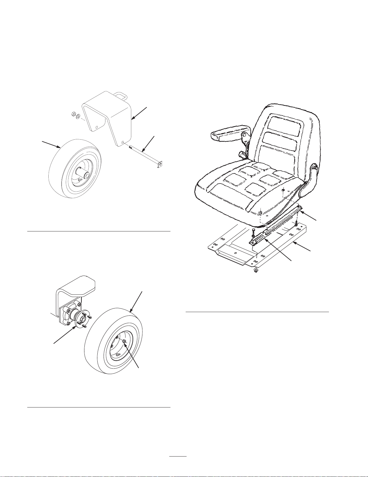
Installing the Rear Wheel
Installing the Seat
Model 03422—Two Wheel Drive
Mount the wheel assembly to the rear castor fork with 2 flat
washers, axle, and locknut. Position the washers on the
outside of the fork (Fig. 1). Tighten the nut to 45–65 ft.-lb.
(3–5 N⋅m).
2
3
1
Figure 1
1. Wheel assembly
2. Rear castor fork
3. Axle
The traction unit is shipped without the seat assembly.
Deluxe Seat Kit, Model 30797, or Standard Seat Kit, Model
30796, must be installed as follows:
1. Remove the shipping ties securing the lower seat slides
to the upper seat slides. Note the orientation of the
lower slides for correct reinstallation (Fig. 3).
2
Model 03427—Three Wheel Drive
1. Mount the wheel assembly onto the rear wheel hub
(Fig. 2).
1
2
3
Figure 2
1. Wheel assembly
2. Rear wheel hub
2. Install the lug nuts (Fig. 2) and tighten them to 45–65
ft.-lb. (3–5 N⋅m).
3. Lug nut
3
1
Figure 3
1. Lower seat slide
2. Upper seat slide
3. Seat plate
2. Insert the lower slides onto the upper slides (Fig. 3).
3. On the Deluxe Seat, check the alignment of the
mounting holes with the seat plate. If the holes do not
align, remove the machine screws securing the upper
slides to the seat bottom. Move the seat slides inward to
the next set of mounting holes and secure them with the
machine screws and 4 locknuts (M8). Apply Loctite to
the fasteners.
4. Loosely secure slides to seat plate with fasteners
supplied with seat (Fig. 3).
Note: Mount the seat in the forward holes to attain forward
adjustment.
5. Tighten the flange nuts and check the operation of the
seat.
14
Page 15
Note: For operators that are lightweight, (less than 150 lb.
[68 kg]) and short in stature (less than 5 ft.-4 in. [163 cm]
tall), an optional weight kit (Toro part no. 80-4210) for seat
model 30796 is available from your Authorized Toro
Distributor.
Mounting the Carrier Frames to
the Cutting Units
1. Remove the cutting units from the cartons. Adjust them
per the Cutting Unit Operator’s Manual.
Adjusting the Rear Carrier
Frame Height
1. Slide the rear carrier frame onto the rear lift arm pivot
rod (Fig. 4). Do not install the carrier frame to the
cutting unit at this time.
3
1
3
2
4
Figure 4
1. Rear carrier frame
2. Pivot rod
3. Up stop
4. Lift cylinder
2. Position a carrier frame onto each cutting unit, aligning
the mounting holes with the mounting links (Fig. 5).
3. Secure each mounting link to the carrier frame with a
capscrew (3/8 x 2-1/4 in.), 2 flat washers, and a locknut,
as shown in Figure 5. Position a washer on each side of
the link when mounting. Torque to 31 ft.-lb. (42 N⋅m).
1
2
3
Figure 5
1. Carrier frame
2. Mounting link
3. Bearing housing cover
2. Raise the lift arms and carrier frame fully.
3. Press down on one end of the carrier frame until the up
stop on the opposite end contacts the underside of the
foot step (Fig. 4). The distance between the up stop and
the underside of the foot step, on the end pressed down,
should be approximately 1/4 in. (6 mm). If the distance
is not 1/4 in. (6 mm), an adjustment to the lift cylinder
is required. If the distance is correct, remove the carrier
frame and proceed with the setup instructions.
4. If an adjustment to the lift cylinder is required, proceed
as follows:
A. Remove the clevis pin securing the rod end of the
lift cylinder to the lift arm (Fig. 4).
B. Loosen the hex nut securing the clevis to the
cylinder rod.
C. Rotate the clevis end in or out until 1/4 in. (6 mm)
clearance is attained. Check the adjustment and
repeat steps 2–3 as required.
D. Tighten the hex nut and connect the cylinder rod end
to the lift arm (Fig. 4).
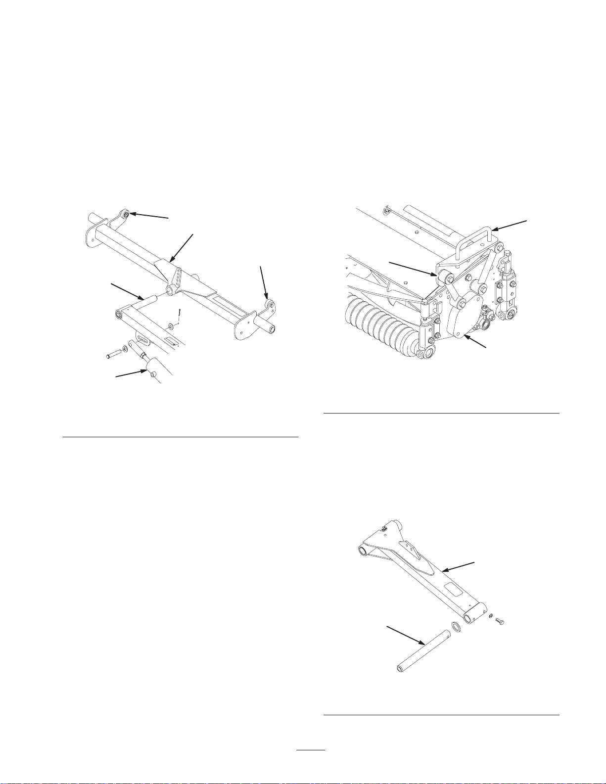
Installing the Front Lift Arms
1. Insert a pivot rod into the left lift arm and align the
mounting holes (Fig. 6).
2. Secure the pivot rod to the lift arm with a capscrew
(5/16 x 7/8 in.) and lock washer.
1
2
Figure 6
1. Lift arm 2. Pivot rod
15
Page 16
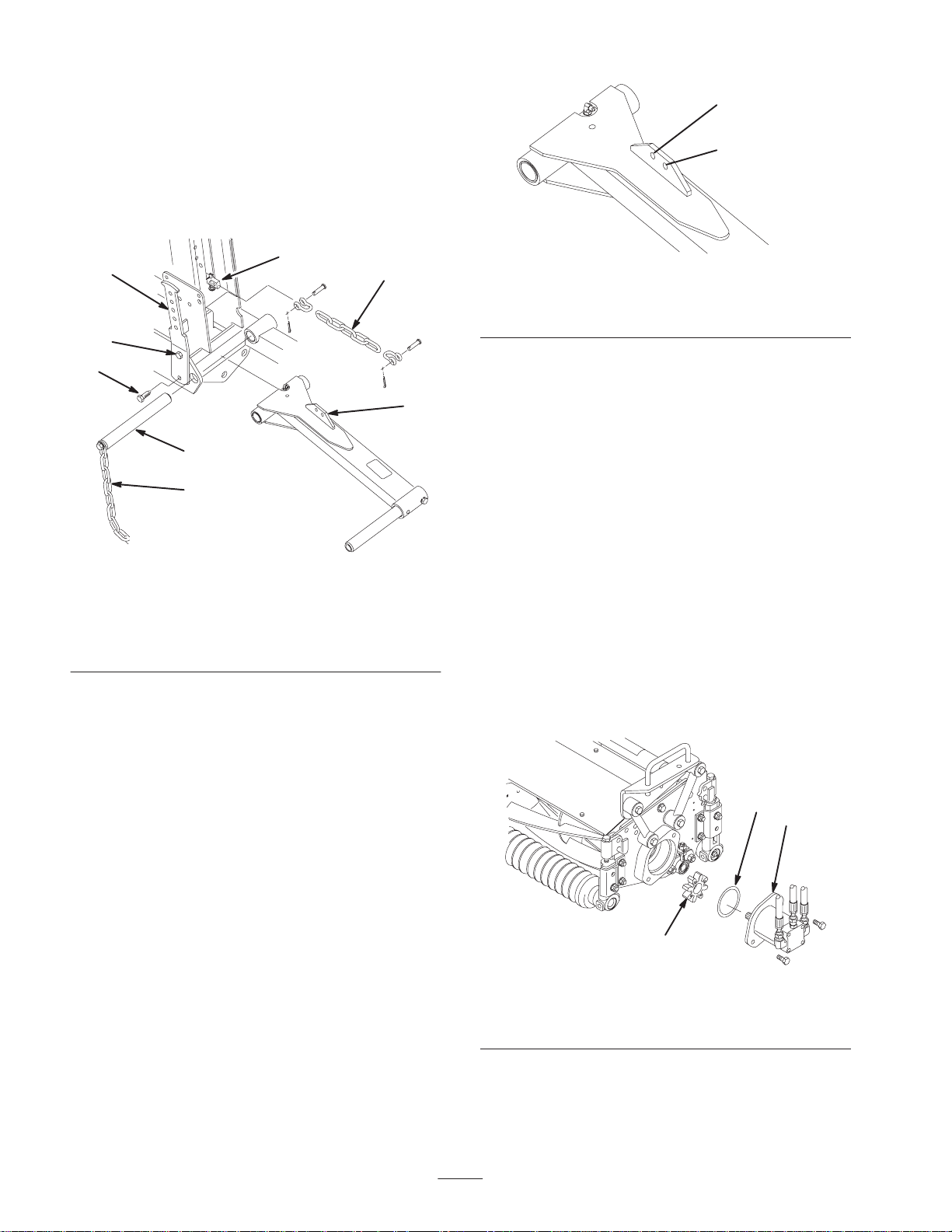
3. Loosen the top capscrew securing the left
counterbalance arm to the frame (Fig. 7).
4. Remove the bottom capscrew and nut securing the left
counterbalance arm to the frame (Fig. 7).
5. Rotate the counterbalance arm outward, allowing
removal of the lift arm pivot pin and tipper chain
(Fig. 7).
7
1
6
2
3
8
RM 2300
(Inner Hole)
RM 2600
(Outer Hole)
Figure 8
1. Spider coupling
2. Reel motor
3. O-ring
Mounting the Cutting Unit
Drive Motors
4
5
Figure 7
1. Counterbalance arm
2. Top capscrew
3. Bottom capscrew
4. Lift arm pivot pin
5. Tipper chain
6. Cylinder pin
7. Lift arm tab
6. Position the lift arm between the frame members, align
the mounting holes, and install the pivot pin (Fig. 7).
Insert the pivot pin so that the counterbalance arm fits
into the slot in the pin. Do not secure the counterbalance
arm at this time.
7. Secure one end of the lift chain to the lift cylinder pin
with a clevis pin and cotter pin.
8. Secure the other end of the lift chain to the hole in the
lift arm mounting tab with clevis pins and cotter pins.
Use the appropriate hole in the lift arm as designated in
Figure 8.
1. Position the cutting units in front of the pivot rods.
2. Remove the bearing housing cover (Fig. 5) from the
inside end of the right-hand cutting unit. Install the
cover and gasket (supplied with the cutting unit) on the
outside end. Locate the spider coupling (Fig. 9) shipped
in the bearing housing.
3. Insert the o-ring (supplied with the cutting unit) on the
flange of the drive motor (Fig. 9).
4. Mount the motor and the spider coupling to the drive
end of the cutting unit and secure them with 2
capscrews provided with the cutting unit (Fig. 9).
5. On the center and left-hand cutting units, remove the
bearing housing cover and install the gasket (supplied
with the cutting units).
3
2
9. Repeat the procedure on the right-hand lift arm.
1. Spider coupling
2. Reel motor
16
1
Figure 9
3. O-ring
Page 17

Mounting the Cutting Units
Installing the Counterbalance
1. Slide a thrust washer onto the lift arm pivot rod
(Fig. 10).
2. Slide the cutting unit carrier frame onto the pivot rod
and secure it with a flat washer and flange head
capscrew (Fig. 10).
Note: On the rear cutting unit, position the thrust washer
between the rear of the carrier frame and the flat washer.
2
3
Figure 10
1. Thrust washer
2. Carrier frame
3. Secure a tipper chain to the top of each Reelmaster
2300 carrier frame and to the bottom of each
Reelmaster 2600 carrier frame with a capscrew, washer,
and locknut (Fig. 11).
3. Flat washer and flange
head capscrew
1
Springs
Warning
Use caution when tensioning the springs as they
are under heavy load.
The counterbalance springs help balance the cutting units to
allow equal amounts of weight (down pressure) to be
distributed to each end of the cutting unit. The springs also
transfer weight from the cutting units to the traction unit
therefore, increasing traction.
The following are recommended settings for the
counterbalance springs. Minor changes may be required to
achieve optimum performance for your turf conditions. The
weight, at each end of the cutting unit, can be checked
easily with a spring scale.
• Increasing the spring tension reduces the weight on
inboard end of the cutting unit and increases the
weight on the outboard end.
• Decreasing the spring tension increases the weight on
the inboard end of the cutting unit and reduces the
weight on outboard end.
Reelmaster 2300
1. Hook the spring into the third hole from the top on the
inboard side of both front cutting unit lift tabs and on
the rear cutting unit lift tab (Fig. 12).
Note: Selecting the #4 hole position (increasing the spring
tension) will reduce the weight on the inboard end of the
cutting unit, increase the weight on the outboard end of the
cutting unit, and increase traction. Selecting the #2 hole
position has the opposite affect.
1
2
Figure 11
1. Tipper chain (RM 2300)
2. Tipper chain (RM 2600)
4. Grease all lift arm and carrier frame pivot points.
3. Carrier frame
3
1
Figure 12
1. Cutting unit lift tab
17
Page 18

2. Secure the other end of the spring to the appropriate
hole (see below) on the front and rear counterbalance
arms (Fig. 13 & 14) with the spring shackle, clevis pin,
and cotter pin.
• Fourth hole from the top for 5 blade reels
5. To tension the counterbalance springs, proceed as
follows:
A. Remove the cotter pin and clevis pin securing the
spring shackle to the counterbalance arm. Do not
remove the other clevis pin.
• Third hole from the top for 8 blade reels
• Top hole for reels with baskets
Note: On the rear counterbalance spring, install the vinyl
cover over the spring before installing.
Note: Increasing the spring tension will reduce the weight
on the inboard end of the cutting unit, increase the weight
on the outboard end of the cutting unit, and increase
traction. Decreasing the spring tension has the opposite
affect.
4
1
2
3
5
Figure 13
1. Counterbalance arm
2. Top capscrew
3. Bottom capscrew
4. Spring shackle
5. Clevis pin and cotter pin
B. Move the shackle up or down on the counterbalance
arm until it is aligned with the desired hole on the
arm. Install the clevis pin and cotter pin.
Reelmaster 2600
1. Mount a spring anchor to the rear inboard side of each
front cutting unit lift tab with 2 capscrews (1/4 x 3/4 in.)
and locknuts, as shown in Figure 15.
2
1
Figure 15
1. Cutting unit lift tab 2. Spring anchor
1 23
Figure 14
1. Rear counterbalance
spring
2. Vinyl cover
3. Spring shackle
3. Insert the breaker bar into the square hole in the
counterbalance arm and pivot the arm back to its
original position, aligning the mounting holes.
4. Secure the bottom of the counterbalance arm to the
frame with the capscrew and nut previously removed.
Tighten the top capscrew (Fig. 13).
2. On the front cutting units, hook the spring into the
second hole from the bottom (#3 position) in the spring
anchor (Fig. 15).
Note: Selecting the #4 hole position (increasing the spring
tension) will reduce the weight on the inboard end of the
cutting unit, increase the weight on the outboard end of the
cutting unit, and increase traction. Selecting the #2 hole
position has the opposite affect.
3. On the rear cutting unit, hook the spring into the top
hole on the rear cutting unit lift tab.
Note: Increasing the spring tension will reduce the weight
on the inboard end of the cutting unit, increase the weight
on the outboard end of the cutting unit, and increase
traction. Decreasing the spring tension has the opposite
affect.
18
Page 19

4. Secure the other end of the spring to the appropriate
hole (see below) on the front and rear counterbalance
arms (Fig. 16 & 17) with the spring shackle with the
chain, clevis, clevis pin, and cotter pin.
• Third hole from the top for 5 blade reels
8. Secure the bottom of the counterbalance arm to the
frame with the capscrew and nut previously removed.
Tighten the top capscrew (Fig. 16).
9. To tension the counterbalance springs proceed as
follows:
• Second hole from the top for 8 blade reels
• Top hole for reels with baskets
Note: On rear counterbalance spring, install vinyl cover
over spring before installing.
5. Secure the other end of the spring to the second hole
from the top with the spring shackle with the chain,
clevis, clevis pin, and cotter pin (Fig. 16).
6. On the rear counterbalance arms, install the vinyl cover
over the spring before hooking the other end of the
spring into the spring shackle in the second hole from
the top (Fig. 17).
1
2
4
5
3
Figure 16
1. Counterbalance arm
2. Top capscrew
3. Bottom capscrew
4. Spring shackle
5. Clevis pin and cotter pin
6. Chain, clevis, and clevis
pin
A. Remove the cotter pin and clevis pin securing the
spring shackle to the counterbalance arm. Do not
remove the other clevis pin.
B. Move the shackle up or down on the counterbalance
arm until it is aligned with the desired hole on the
arm. Install the clevis pin and cotter pin.
Adding Rear Ballast
This unit complies with ANSl B71.4–1990 Standard and all
applicable European requirements when equipped with rear
ballast. Use the following chart to determine the weight or
combinations of weights needed.
Cutting Unit
Configuration
RM 2300D—2WD (1) 83-9370, (1) 83-9390
RM 2300D—2WD with
Baskets
RM 2300D—3WD (1) 83-9390, (1) 94-3663
RM 2300D—3WD with
Baskets
RM 2600D—2WD (2) 83-9390, (1) 94-3663
RM 2600D—3WD (1) 83-9370, (1) 83-9390
Note: All configurations require calcium chloride in the
rear tire. Tires should be filled to approximately 75%
capacity (valve level with valve at the top) (60 lb. fluid or
74 lb. tire and fluid).
Weight Kits Required
(1) 83-9370,
(1) 83-9390, (1) 94-5974
(2) 83-9390, (1) 94-3663
1 23
Figure 17
1. Rear counterbalance
spring
2. Vinyl cover
3. Spring shackle
7. Insert the breaker bar into the square hole in the
counterbalance arm and pivot the arm back to its
original position, aligning the mounting holes.
Important If a puncture occurs in a tire with calcium
chloride, remove the unit from the turf area as quickly as
possible. To prevent possible damage to the turf,
immediately soak the affected area with water.
Either Type 1 (77%) or Type 2 (94%) commercial calcium
chloride flake may be used.
Plain water freezes solid at 32°F (0°C). The 3-1/2 lb.
(1.6 kg) calcium chloride to 1 gallon (3.8 l) of water
solution is slush free to –12°F (–24°C) and will freeze solid
at –52°F (–46°C). The 5 lb. (2.3 kg) per gallon (liter)
solution is slush free to –50° F (–45°C) and will freeze
solid at –62°F (–52°C).
19
Page 20

Affixing the Decals
Using the dimensions shown in Figure 18, locate and affix
a Reelmaster 2300 or 2600 decal to the skirt on each side of
the machine.
To ease installation of decal use the following procedure:
1. In a spray bottle, mix 1 ounce of liquid soap and 20
ounces of water.
2. Spray the skirt panel with the soap solution, peel the
backing off of the decal, position the decal on the skirt,
and adjust as necessary.
Danger
Battery electrolyte contains sulfuric acid which is a
deadly poison and causes severe burns.
• Do not drink electrolyte and avoid contact with
skin, eyes or clothing. Wear safety glasses to
shield your eyes and rubber gloves to protect
your hands.
• Fill the battery where clean water is always
available for flushing the skin.
3. Run a plastic squeegee over the decal to remove any
excess soap solution.
4. Peel the front cover paper off of the decal.
1/2 in.
(13 mm)
12-3/4 in.
(324 mm)
1
Figure 18
1. Decal
Activating and Charging the
Battery
Warning
Battery posts, terminals, and related accessories
contain lead and lead compounds, chemicals
known to the State of California to cause cancer
and reproductive harm. Wash hands after
handling.
2. Replace the filler caps with the vents pointing to the
rear (toward the fuel tank) and connect a 3 to 4 amp
battery charger to the battery posts. Charge the battery
at a rate of 3 to 4 amperes for 4 to 8 hours.
Warning
Charging the battery produces gasses that can
explode.
Never smoke near the battery and keep sparks and
flames away from battery.
3. When the battery is charged, disconnect the charger
from the electrical outlet and battery posts.
4. Remove the filler caps. Slowly add electrolyte to each
cell until the level is up to the fill ring. Install the filler
caps.
Important Do not overfill the battery. Electrolyte will
overflow onto other parts of the machine and severe
corrosion and deterioration will result.
5. Install the positive cable (red) to the positive (+)
terminal and the negative cable (black) to the negative
(—) terminal of the battery (Fig. 19) and secure them
with capscrews and nuts. Slide the rubber boot over the
positive terminal to prevent a possible short from
occurring.
Warning
If the battery is not filled with electrolyte or activated, bulk
electrolyte with 1.260 specific gravity must be purchased
from a local battery supply outlet and added to the battery.
1. Remove the filler caps from the battery and slowly fill
each cell until the electrolyte is just above the plates.
Incorrect battery cable routing could damage the
machine and cables causing sparks. Sparks can
cause the battery gasses to explode, resulting in
personal injury.
• Always disconnect the negative (black) battery
cable before disconnecting the positive (red)
cable.
• Always connect the positive (red) battery cable
before connecting the negative (black) cable.
20
Page 21

3
2
11
1
Figure 19
1. Battery
2. Positive (+) batter cable
3. Negative (–) battery cable
Before Operating
Caution
If you leave the key in the ignition switch, someone
could accidently start the engine and seriously
injure you or other bystanders.
Before servicing or making adjustments to the
machine, stop the engine and remove the key from
the ignition switch.
Checking the Crankcase Oil
Important Check the oil level every 5 operating hours
or daily. Change the oil after every 50 hours of operation.
The engine is shipped with oil in the crankcase; however,
the oil level must be checked before and after the engine is
first started.
Figure 20
1. Dipstick
3. If the oil level is low, remove the oil fill cap (Fig. 21)
and gradually add small quantities of oil, checking the
level frequently, until the level reaches the FULL mark
on the dipstick.
1
Figure 21
1. Oil fill cap
Filling the Fuel Tank
The engine runs on No. 2 diesel fuel.
The fuel tank capacity is approximately 6.5 gallons.
Crankcase capacity is approximately 3 qts. (2.8 l) with the
filter.
The engine uses any high-quality 10W30 detergent oil
having the American Petroleum Institute (API) “service
classification” CD.
1. Position the machine on a level surface.
2. Remove the dipstick (Fig. 20) and wipe it with a clean
rag. Push the dipstick down into the dipstick tube and
make sure it is seated fully. Pull the dipstick out and
check the oil level.
Danger
Under certain conditions, diesel fuel and fuel
vapors are highly flammable and explosive. A fire
or explosion from fuel can burn you and others
and can cause property damage.
• Use a funnel and fill the fuel tank outdoors, in
an open area, when the engine is off and is cold.
Wipe up any fuel that spills.
• Do not fill the fuel tank completely full. Add fuel
to the fuel tank until the level is 1 in. (25 mm)
below the bottom of the filler neck. This empty
space in the tank allows the fuel to expand.
• Never smoke when handling fuel, and stay away
from an open flame or where fuel fumes may be
ignited by a spark.
• Store fuel in a clean, safety-approved container
and keep the cap in place.
21
Page 22

1. Clean the area around the fuel tank cap (Fig. 22).
Caution
1
Figure 22
1. Fuel tank cap
2. Remove the fuel tank cap.
3. Fill the tank to about 1 in. (25 mm) below the top of the
tank, (bottom of the filler neck). Do not overfill. Install
the cap.
4. Wipe up any fuel that may have spilled to prevent a fire
hazard.
Checking the Cooling System
If the engine has been running, the pressurized,
hot coolant can escape and cause burns.
• Do not open the radiator cap when the engine is
running.
• Use a rag when opening the radiator cap, and
open the cap slowly to allow steam to escape.
1. Carefully remove the radiator cap (Fig. 24).
1
Figure 24
1. Radiator cap
The cooling system is filled with a 50/50 solution of water
and permanent ethylene glycol anti-freeze. Check the
coolant level at the beginning of each day before starting
the engine. The cooling system capacity is approximately
5-1/4 quarts.
1. Clean debris off of the radiator screen, radiator, and oil
cooler (Fig. 23) daily or hourly if conditions are
extremely dusty and dirty; refer to Cleaning the
Radiator and Screen, page 36.
1
3
2
Figure 23
1. Radiator screen
2. Radiator
3. Oil cooler
2. Check the coolant level in the radiator. The radiator
should be filled to the middle of the horizontal filler
neck.
3. If the coolant level is low, replenish the system. Do not
overfill.
4. Install the radiator cap.
Checking the Hydraulic System
Fluid
The hydraulic system is designed to operate on anti-wear
hydraulic fluid. The hydraulic reservoir is filled at the
factory with approximately 3.3 gallons (12.5 l) of Mobil
424 hydraulic fluid. Check the level of hydraulic fluid
before the engine is first started and daily thereafter.
Group 1 Hydraulic Fluid (Recommended
for ambient temperatures consistently
below 100F.):
Note: The fluids within this group are interchangeable.
ISO type 46/68 anti–wear hydraulic fluid
Mobil Mobil Fluid 424
Amoco Amoco 1000
22
Page 23

International Harvester Hy–Tran
T exaco TDH
Shell Donax TD
Union Oil Hydraulic/Tractor Fluid
Chevron Tractor Hydraulic Fluid
BP Oil BP HYD TF
Boron Oil Eldoran UTH
Exxon Torque Fluid
Conoco Power–Tran 3
Kendall Hyken 052
Phillips HG Fluid
reservoir with Mobil 424 or equivalent hydraulic fluid
until the level in it reaches the bottom of the sight
gauge. Do not overfill.
1
2
Group 2 Hydraulic Fluid (Biodegradable):
ISO VG 32/46 anti–wear hydraulic fluid
Mobil EAL 224H
Important Due to the nature of biodegradable fluids, it
is critical that the fluid be changed at the recommended
intervals or severe hydraulic component damage may
occur.
Note: The fluid in this group is not compatible with the
fluids in group 1.
Important These hydraulic fluids are specified to allow
optimal operation of the machine in a wide range of
temperatures encountered. The group 1 fluids are a
multi-viscosity hydraulic fluids which allows operation at
lower temperatures without the increased viscosity, which
is associated with straight viscosity fluids.
Note: When changing from one type of hydraulic fluid to
the other, be certain to remove all the old fluid from the
system, because some brands of one type are not
completely compatible with some brands of the other type
of hydraulic fluid.
Important Use only types of hydraulic fluids specified.
Other fluids could cause system damage.
Figure 25
1. Hydraulic reservoir cap 2. Sight gauge
Important To prevent system contamination, clean the
top of the hydraulic fluid containers before puncturing.
Ensure that the pour spout and funnel are clean.
4. Install the reservoir cap. Wipe up any fluid that may
have spilled.
Inspecting the Fuel Filter
Inspect the fuel filter bowl daily for water or other
contaminants. If water or other contaminants are present,
they must be removed before commencing operation.
1. Close the fuel shut-off above the filter (Fig. 26).
2. Unscrew the nut securing the bowl to the filter head.
Remove water or other contaminants from the bowl.
Note: A red dye additive for the hydraulic system fluid is
available in 2/3 oz bottles. One bottle is sufficient for 4–6
gal. of hydraulic oil. Order Part No. 44-2500 from your
Authorized Toro Distributor.
1. Position the machine on a level surface.
2. Check the fluid level by viewing it in the sight gauge
(Fig. 25). If the fluid is cold, the level should be at the
bottom of the gauge. If the fluid is hot, the level should
be at the center of the gauge.
3. If the fluid level is not at least at the bottom of the
gauge when it is cold, remove the cap from the
hydraulic fluid reservoir (Fig. 25) and slowly fill the
2
Figure 26
1. Fuel shut-off 2. Fuel filter
3. Inspect the fuel filter and replace it if it is dirty; refer to
Replacing the Fuel Filter, page 37.
23
1
Page 24

4. Install the bowl to the filter head. Make sure that the
o-ring is positioned properly between the bowl
mounting nut and filter head.
5. Open the fuel shut-off above the filter.
6. Open the bleed screw on the filter mounting, allowing
the bowl to fill with fuel. Close the bleed screw.
bottom of the pedal to move backward or to assist in
stopping when moving forward (Fig. 28). Also, allow the
pedal to move or move it to the neutral position to stop the
machine. For operator comfort, do not the rest heel of your
foot on reverse when operating forward.
3
Checking the Tire Pressure
The tires are over-inflated for shipping. Therefore, release
some of the air to reduce the pressure. The correct air
pressure in the tires is 16–20 psi (110–138 kPa).
Important Maintain the recommended pressure in all
tires to ensure a good quality-of-cut and proper machine
performance. Do not under-inflate.
Checking the Reel to Bedknife
Contact
Each day before operating, check the reel to bedknife
contact, regardless if the quality of cut had previously been
acceptable. There must be light contact across the full
length of the reel and bedknife; refer to Adjusting the Reel
to the Bedknife in the Cutting Unit Operator’s Manual.
Checking the Torque of the
Wheel Nuts
Warning
1. Traction pedal
2. Speed selector
1
2
Figure 27
3. Pedal stop
Failure to maintain proper torque of the wheel
nuts could result in personal injury.
Torque the wheel nuts to 45–65 ft.-lb. (61–88 Nm)
after 1–4 hours of operation and again after 10
hours of operation. Torque every 200 hours
thereafter.
Operation
Note: Determine the left and right sides of the machine
from the normal operating position.
Controls
Traction and Stopping Pedal
The traction pedal (Fig. 27) has three functions: to make
the machine move forward, to move it backward, and to
stop the machine. Using the heel and toe of the right foot,
depress the top of the pedal to move forward and the
Figure 28
Speed Selector
The speed selector is a cam lever at the side of the traction
pedal (Fig. 27) that can be rotated to maintain desired
speed.
The reverse pedal stop (under the pedal) (Fig. 27) is set at
the factory to provide 3 MPH maximum speed in reverse.
Starter Switch
The starter switch (Fig. 29), used to start, stop, and preheat
the engine, has four positions: OFF, ON, START and
GLOW PLUGS (PREHEAT). Rotate the key
counterclockwise (GLOW PLUG position) and hold for
approximately 20 to 30 seconds. Then rotate the key
clockwise (START position) to engage the starter motor.
Release the key when the engine starts. The key will move
24
Page 25

automatically to the ON/RUN position. To shut the engine
off, rotate the key counterclockwise to the OFF position.
Remove the key from the switch and install the switch
cover (Fig. 29) to prevent accidental starting.
11
14
Cutting Unit Drive Switch
The switch (Fig. 29) has two positions: ENGAGE and
DlSENGAGE. The push-pull switch operates a solenoid
valve on the valve bank, to drive the cutting units. A yellow
light on the dash indicates when the reels are rotating.
7
8
2
1. Starter switch and cover
2. Throttle
3. Cutting unit lift lever
4. Cutting unit drive switch
5. Hour meter
6. Water temperature gauge
7. Oil pressure light
1 12
9
Figure 29
8. Alternator light
9. Glow plug indicator light
10. High water temperature
11. Reel operating light
12. Cold start button
shut-down light
10
6
Hour Meter
The hour meter (Fig. 29) indicates the total hours of
machine operation. The Hour Meter starts to function
whenever the key switch is rotated to “ON” position.
3
Temperature Gauge
The temperature gauge (Fig. 29) registers coolant
temperature in the system.
5
Oil Pressure Light
The oil pressure light (Fig. 29) glows if the engine oil
pressure drops below a safe level.
Water Temperature Light
The water temperature light (Fig. 29) glows and the engine
automatically shuts down when the engine coolant
temperature gets too high.
Alternator Light
The amp light (Fig. 29) should be off when the engine is
running. If it is on, the charging system should be checked
and repaired as necessary.
Throttle
Moving the throttle (Fig. 29) upward increases the engine
speed and downward decreases the engine speed.
Cutting Unit Lift Lever
The lift lever (Fig. 29) has three positions: LOWER,
RAISE, and NEUTRAL. To lower the cutting units to the
ground, move the lift lever forward. When lowering the
cutting units, make sure that the front hydraulic cylinder is
completely retracted before releasing the lift lever. The
cutting units will not operate unless the cylinder is
retracted. To raise the cutting units, pull the lift lever
rearward to the RAISE position. To decrease play in the
lever, tighten the retaining locknut.
Glow Plug Indicator
The indicator light (Fig. 29) will glow when glow plugs are
operating.
Cold Start Button
When starting a cold engine, press the cold start button
(Fig. 29) to electrically de-clutch the traction pump. When
the engine starts, release the button.
Parking Brake
Whenever the engine is shut off, the parking brake must be
engaged to prevent accidental movement of the machine.
To engage the parking brake, pull back on the lever.
25
Page 26

Drive Engagement Control
(Model 03426 Only)
The drive engagement control is located on the lower left
side of the operator (Fig. 30). Pull the knob out for 2 wheel
drive; push the knob in for 3 wheel drive.
Deluxe Seat Adjustments
Weight Adjustment (Fig. 32)—Push the lever up or down
to adjust to the operator’s weight. Lever up for a light
operator, lever in middle position for a medium weight
operator, or lever down for a heavy operator.
Inclining Backrest (Fig. 32)—Turn the handle to adjust the
angle of the backrest (Deluxe Seat only).
1
Figure 30
1. Drive engagement control—pull out for two wheel drive; push in
for three wheel drive
Reel Speed Control
To obtain the desired clip rate (reel speed), rotate the reel
speed control knob (Fig. 31) to the appropriate setting for
the height-of-cut setting and mower speed; refer to
Selecting the Clip Rate, page 29.
Backlap Control
Rotate the knob (Fig. 31) clockwise for backlapping and
counterclockwise for mowing. Do not change the knob
position when the reels are rotating.
2
1
2
3
1
Figure 32
1. Fore and aft lever
2. Weight adjustment lever
3. Inclining backrest
Fuel Shut-Off Valves
Close the fuel shut-off valves, under the fuel tank (Fig. 33)
and on the fuel filter (Fig. 34), when storing the machine.
Figure 31
1. Reel speed control 2. Backlap control
Seat Adjustments
Fore and Aft Adjustment (Fig. 32)—Move the lever on the
side of the seat outward, slide the seat to the desired
position, and release the lever to lock the seat into position.
1
Figure 33
1. Fuel shut-off (under the fuel tank)
1
Figure 34
1. Fuel shut-off (on the fuel filter)
26
Page 27

Starting and Stopping the
Engine
8. Close the fuel shut-off valves before storing the
machine.
Important The fuel system may have to be bled if any
of the following situations have occurred:
• Initial start up of a new engine.
• Engine has ceased running due to lack of fuel.
• Maintenance has been performed upon fuel system
components; i.e. filter replaced, etc.
Refer to Bleeding the Fuel System, page 27.
1. Be sure that the parking brake is set and the reel drive
switch is in the DISENGAGE position.
2. Remove your foot from the traction pedal and make
sure that the pedal is in the neutral position.
3. Move the throttle lever to the full throttle position.
4. Remove the cover from the starter switch. Insert the key
into the switch and rotate it counterclockwise (GLOW
PLUG position). Hold it for approximately 20 to 30
seconds, then rotate the key clockwise (START
position) to engage the starter motor. Release the key
when the engine starts. The key will move
automatically to the ON/RUN position.
Important To prevent overheating of the starter motor,
do not engage the starter longer than 10 seconds. After 10
seconds of continuous cranking, wait 60 seconds before
engaging the starter motor again.
5. For cold weather starting, press the cold start button
to de-clutch the electric traction pump. When the engine
starts, release the button.
6. When the engine is started for the first time, or after
overhauling the engine, operate the machine in forward
and reverse for one to two minutes. Also operate the lift
lever and reel drive switch to be sure of proper
operation of all parts.
Bleeding the Fuel System
1. Park the machine on a level surface. Make sure that the
fuel tank is at least half full.
2. Unlatch and raise the hood.
Danger
Under certain conditions, diesel fuel and fuel
vapors are highly flammable and explosive. A fire
or explosion from fuel can burn you and others
and can cause property damage.
• Use a funnel and fill the fuel tank outdoors, in
an open area, when the engine is off and is cold.
Wipe up any fuel that spills.
• Do not fill the fuel tank completely full. Add fuel
to the fuel tank until the level is 1 in. (25 mm)
below the bottom of the filler neck. This empty
space in the tank allows the fuel to expand.
• Never smoke when handling fuel, and stay away
from an open flame or where fuel fumes may be
ignited by a spark.
• Store fuel in a clean, safety-approved container
and keep the cap in place.
3. Open the fuel shut-off valve under the fuel tank and on
the fuel filter (Fig. 35).
4. Open the 2 bleed screws on the side of the fuel filter
mounting head (Fig. 35), allowing the bowl to fill with
fuel. Close the bleed screws when the bowl is filled.
Turn the steering wheel to the left and right to check the
steering response. Then shut the engine off and check
for oil leaks, loose parts, and any other noticeable
malfunctions.
Caution
Shut the engine off and wait for all moving parts to
stop before checking for oil leaks, loose parts, and
other malfunctions.
7. To stop the engine, move the throttle control downward
to the IDLE position, move the reel drive switch to
DISENGAGE, and rotate the ignition key to OFF.
Remove the key from the switch and install the switch
cover to prevent accidental starting.
2
3
Figure 35
1. Fuel shut-off
2. Bleed screws (2)
5. On the front of the engine (by the oil filter) locate the
transfer pump inlet screw. Note the angle of the fitting
on the transfer pump inlet and loosen the screw (left
screw only).
27
3. Bowl
1
Page 28

6. When a steady stream of fuel flows out of the transfer
pump screw, tighten the screw, retaining the angle of the
fitting before loosening (Fig. 36).
1. Be sure that the parking brake is set and all bystanders
are away from the area of operation. Keep hands and
feet away from the cutting units.
7. Loosen the injection pump inlet screw on the front of
the engine (Fig. 36).
8. Pump the priming lever (Fig. 36) until a steady stream
of fuel flows out of the injection pump inlet screw, then
tighten the screw. Do not over-tighten the screw as
damage may occur.
9. Start the engine. If it still does not run smoothly after
several minutes, crack each injector nut until fuel (no
bubbles) comes out.
1
5
3
2. With the operator off of the seat, the backlap knob
rotated counterclockwise, the traction pedal in neutral,
and the reel switch in the OFF position, the engine
should start. If either the traction pedal is depressed or
the reel switch is turned ON, with the operator off of the
seat, the engine should stop. Correct the problem if it is
not operating properly.
3. With the engine running, the operator off of the seat,
and the backlap knob rotated clockwise, the engine
should not stop when the reel switch is turned ON.
Correct the problem if it is not operating properly.
4
4. With the operator on the seat, the engine running, and
the reel switch in the ON position, the dash indicator
light should be glowing and the reel motors turning
when the lift cylinder is fully retracted. As the lift
cylinder is extended, the light should go out and the reel
motors should stop turning. Correct the problem if it is
not operating properly.
5. With the operator on the seat, the engine must not start
with either the reel switch engaged or the traction
control engaged. Correct the problem if it is not
operating properly.
Towing the Traction Unit
2 See Inset
Figure 36
1. Transfer pump screw
2. Transfer pump inlet screw
location
3. Injection pump inlet screw
4. Priming lever
5. Note fitting angle
6. Injector nuts
3
Checking the Operation of the
Interlock Switches
Caution
If safety interlock switches are disconnected or
damaged the machine could operate unexpectedly
causing personal injury.
• Do not tamper with the interlock switches.
• Check the operation of the interlock switches
daily and replace any damaged switches before
operating the machine.
• Replace switches every two years regardless of
whether they are operating properly or not.
In case of an emergency, the machine can be towed for a
short distance. However, we do not recommend this as a
standard procedure.
Important Do not tow the machine faster than 2–3
MPH because the drive system may become damaged. If
the machine must be moved a considerable distance,
transport it on a truck or trailer.
1. Locate the bypass valve on the pump (Fig. 37) and
rotate it 90° (the bypass valve lever should be
horizontal when it is open).
1
Figure 37
1. Bypass valve
28
Page 29

2. Before starting the engine, close the bypass valve by
rotating it 90° (the bypass valve lever should be
vertical when closed). Do not start the engine when the
valve is open.
1. Verify the height-of-cut setting on the cutting units.
Using the column of the chart listing either 5 or 8 blade
reels, find the height of cut listing nearest the actual
height-of-cut setting. Look across the chart to find the
number corresponding to that height of cut.
Operating Characteristics
Caution
This machine produces sound levels in excess of
85dBA at the operators ear and can cause hearing
loss through extended periods of exposure.
Wear hearing protection when operating this
machine.
Practice operating the machine and become thoroughly
familiar with it. Because of its hydrostatic transmission and
choices or two or three wheel drive (model 03427 only), its
characteristics differ from many turf maintenance
machines. Points to consider when operating are the
traction drive, engine speed, and load on the cutting units.
Regulate the traction pedal to keep the engine RPM high
and somewhat constant while mowing to maintain adequate
power for the traction and cutting units. Adjust the speed
selector to maintain constant ground speed and quality of
cut. However, when on hilly terrain, do not use the speed
selector.
Follow the operating guidelines presented in this manual
and know how to operate the machine safely on all types of
terrain. Use the Slope Chart, page 9, to assist in
determining slope angles of questionable areas. Hills (or
slopes) over 15 degrees should be traversed or mowed up
and down, not side to side, and hills over 20 degrees should
generally be avoided unless special safeguards, skills, and
conditions exist. Always plan well ahead to avoid the need
for sudden stops, starts, or turns. To stop, use the reverse
pedal for braking. Before stopping the engine, disengage all
controls, move the throttle to the lDLE position, and set the
parking brake.
2. Turn the reel speed control knob (Fig. 38) to the number
setting determined in step 1.
1
Figure 38
1. Reel speed control
3. Operate the machine for several days, then examine the
cut to ensure satisfaction with the quality of cut. The
reel speed knob may be set one position on either side
of the position indicated on the chart to account for
differences in grass condition, grass length removed,
and personal preference of the superintendent.
Variable Reel Speed Selection Chart—5 Blade
Reel
3WD
Height of Cut (in.)
2-1/2 (2.50) 3 5
2-3/8 (2.38) 3 5
2-1/4 (2.25) 4 5
2-1/8 (2.13) 4 5
Speeds
3–5 MPH
2WD
Speeds
6–7 MPH
Selecting the Clip Rate (Reel
Speed)
To achieve a consistent, high quality of cut, and a uniform
after cut appearance, it is important that the reel speed be
matched to the height of cut.
Adjust the clip rate (reel speed) as follows:
2 (2.00) 4 6
1-7/8 (1.88) 4 6
1-3/4 (1.75) 5 7
1-5/8 (1.63) 5 7
1-1/2 (1.50) 6 9*
1-3/8 (1.38) 6 9*
1-1/4 (1.25) 7 9*
1-1/8 (1.13) 7 9*
1 (1.00) 8 9*
7/8 (.88) 9 9*
3/4 (.75) 9* 9*
29
Page 30

5/8 (.63) 9* 9*
Training Period
1/2 (.50) 9* 9*
3/8 (.38) 9* 9*
* This height-of-cut and/or mowing speed not recommended for
5 blade reels.
Variable Reel Speed Selection Chart—8 Blade
Reel
3WD
Height of Cut (in.)
2-1/2 (2.50) 3* 3
2-3/8 (2.38) 3* 3
2-1/4 (2.25) 3* 3
2-1/8 (2.13) 3* 3
2 (2.00) 3* 3
1-7/8 (1.88) 3 4
1-3/4 (1.75) 3 4
1-5/8 (1.63) 3 4
1-1/2 (1.50) 4 5
1-3/8 (1.38) 4 5
1-1/4 (1.25) 4 6
1-1/8 (1.13) 5 7
Speeds
3–5 MPH
2WD
Speeds
6–7 MPH
Before mowing with the machine, we suggest that you find
a clear area and practice starting and stopping, raising and
lowering cutting units, turning, etc. This training period
will be beneficial to the operator in gaining confidence in
the performance of the machine.
Before Mowing
Inspect the area for debris and clear area if necessary.
Determine the best direction to mow on the previous
mowing direction. Always mow in an alternate pattern
from the previous mowing, so that the grass blades will be
less apt to lay down and therefore be difficult to gather
between the reel blades and bedknife.
Transport Operation
Be sure that the cutting units are in the fully up position,
move the traction pedal stop from under the pedal to allow
full traction pedal travel, and place the throttle control in
the FAST position. While operating on slopes and uneven
terrain, always reduce your speed and use extreme caution
before turning to reduce the risk of tipping or losing
control. Watch carefully for, and avoid, holes in the terrain,
sudden drop-offs, and other hidden hazards. To prevent
costly damage and down time, familiarize yourself with the
width of the machine. Do not attempt to pass between
immovable objects placed close together.
1 (1.00) 5 9
7/8 (.88) 6 9*
3/4 (.75) 7 9*
5/8 (.63) 9 9*
1/2 (.50) 9 9*
3/8 (.38) 9 9*
* This height-of-cut and/or mowing speed not recommended for
8 blade reels.
Inspection and Clean-Up After
Mowing
At the completion of the mowing operation, thoroughly
wash the machine with a garden hose—without a
nozzle—so that excessive water pressure will not cause
contamination and damage to the seals and bearings.
Make sure that the radiator screen, radiator, and oil cooler
are kept free of dirt or grass clippings. After cleaning, it is
recommended that the machine be inspected for possible
hydraulic fluid leaks, damage or wear to the hydraulic and
mechanical components, and the cutting units checked for
sharpness and proper reel to bedknife adjustment.
30
Page 31

Maintenance
Note: Determine the left and right sides of the machine from the normal operating position.
Recommended Maintenance Schedule
Maintenance Service
Interval
After first 10 hours
After first 50 hours • Check the engine RPM (idle and full throttle).
Every 50 hours
Every 100 hours
Every 200 hours
Maintenance Procedure
• Change the engine oil.
• Check the engine belt tension.
• Change the engine oil filter.
• Check the traction belt tension.
• Replace the hydraulic filter.
• Torque the wheel lug nuts.
• Inspect the air filter, dust cup, and burp valve.
• Lubricate all grease fittings.
• Change the engine oil.
• Check the engine belt tension.
• Change the engine oil filter.
• Check the traction belt tension.
• Service the air filter.
• Replace the fuel filter/water separator.
• Replace the hydraulic filter.
• Torque the wheel lug nuts.
• Replace the hydraulic fluid.
Every 400 hours
Every 1000 hours or 2
years, whichever occurs
first
Important Refer to your engine operator’s manual for additional maintenance procedures.
• Check the battery level and connections.
• Inspect the traction linkage movement.
• Check the engine RPM (idle and full throttle).
• Replace moving hoses.
• Replace the safety switches.
• Flush the cooling system and replace the hoses.
• Replace the thermostat.
• Drain and flush the fuel tank.
• Drain and flush the hydraulic tank.
31
Page 32

Daily Maintenance Checklist
Duplicate this page for routine use.
For the week of:
Maintenance Check Item
Check the safety interlock operation.
Check the brake operation.
Check the engine oil level.
Check the cooling system fluid level.
Drain the water/fuel separator
Check the air filter, dust cup, and burp
valve.
Check the radiator and screen for
debris.
Check for unusual engine noises.
1
Check for unusual operating noises.
Check the hydraulic system oil level.
Check the hydraulic hoses for damage.
Check for fluid leaks.
Check the fuel level.
Check the tire pressure.
Check instrument operation.
Mon. Tues. Wed. Thurs. Fri. Sat. Sun.
Check reel-to-bedknife adjustment.
Check height-of-cut adjustment.
Lubricate all grease fittings.
2
Touch up damaged paint.
1
Check the glow plug and injector nozzles, if hard starting, excess smoke, or rough running is noted.
2
Immediately after every washing, regardless of the interval listed
Notation for Areas of Concern
Inspection performed by:
Item Date Information
1
2
3
4
5
6
7
8
9
32
Page 33

Service Interval Chart
Caution
If you leave the key in the ignition switch, someone could accidently start the engine and
seriously injure you or other bystanders.
Remove the key from the ignition and disconnect the wire from the spark plug before you do any
maintenance. Set the wire aside so that it does not accidentally contact the spark plug.
Greasing the Bearings and
Bushings
The traction unit has grease fittings that must be lubricated
regularly with No. 2 General Purpose Lithium Base Grease.
If the machine is operated under normal conditions,
lubricate bearings and bushings after every 50 hours of
operation. Bearings and bushings must be lubricated daily
when operating conditions are extremely dusty and dirty.
Dusty and dirty operating conditions could cause dirt to get
into the bearings and bushings, resulting in accelerated
wear.
The traction unit bearings and bushings that must be
lubricated are: steering column (Fig. 39), steering gears (2)
(under the skirt below the steering sector), steering shaft (2)
(Fig. 40), lift arms (3) (Fig. 41), pivot rods (3) (Fig. 42),
rear lift cylinder pivot (Fig. 43), traction pedal pivot
(Fig. 44) and rear wheel (2WD only) (Fig. 45)
33
Page 34

Also, apply grease to slots in cylinder support (Fig. 46).
Figure 39
Figure 42
Figure 40
Figure 41
Figure 43
Figure 44
34
Page 35

Figure 45
3. Slide the hood to the right side, lift the other side, and
pull it out of the brackets.
4. Reverse the procedure to install the hood.
General Air Cleaner
Maintenance
Check the air cleaner body for damage which could
possibly cause an air leak. Replace a damaged air cleaner
body.
Service the air cleaner filter every 400 hours (more
frequently in extreme dusty or dirty conditions). Do not
over-service the air filter.
Be sure that the cover is sealing around the air cleaner
body.
Servicing the Air Cleaner
1. Release the latches securing the air cleaner cover to the
air cleaner body (Fig. 48). Separate the cover from the
body. Clean the inside of the air cleaner cover.
Figure 46
Removing the Hood
The hood may be easily removed to ease maintenance
procedures in the engine area of the machine.
1. Unlatch and raise the hood.
2. Remove the cotter pin securing the hood pivot to the
mounting brackets (Fig. 47).
1
3
1
Figure 48
1. Air cleaner latches
2. Dust cap
2. Gently slide the filter out of the air cleaner body
(Fig. 48) to reduce the amount of dust dislodged. Avoid
knocking the filter against the air cleaner body.
3. Filter
2
1. Cotter pin
Figure 47
3. Inspect the filter and discard it if it is damaged. Do not
wash or reuse a damaged filter.
35
Page 36

4. Washing Method
A. Prepare a solution of filter cleaner and water and
soak the filter element about 15 minutes. Refer to
the directions on the filter cleaner carton for
complete information.
B. After soaking the filter for 15 minutes, rinse it with
clear water. Maximum water pressure must not
exceed 40 psi to prevent damage to the filter
element. Rinse the filter from the clean side to the
dirty side.
C. Dry the filter element using warm, flowing air
(160°F max.), or allow the element to air-dry. Do
not use a light bulb to dry the filter element because
damage could result.
5. Compressed Air Method
A. Blow the compressed air from the inside to the
outside of a dry filter element. Do not exceed
100 psi to prevent damage to the element.
B. Keep the air hose nozzle at least 2 in. (51 mm) from
the filter and move the nozzle up and down while
rotating the filter element. Inspect the filter for holes
and tears by looking through the filter toward a
bright light.
1
3
Figure 49
1. Radiator screen
2. Radiator
3. Thoroughly clean the oil cooler (Fig. 49) and remove
any other debris that may have collected around the
components.
4. Clean the screen and install it.
3. Oil cooler
2
6. Inspect the new filter for shipping damage. Check the
sealing end of the filter. Do not install a damaged filter.
7. Insert the new filter properly into the air cleaner body.
Make sure that the filter is sealed properly by applying
pressure to the outer rim of the filter when installing.
Do not press on the flexible center of the filter.
8. Install the cover and secure the latches. Make sure that
the cover is positioned with the TOP side up.
Cleaning the Radiator and
Screen
To prevent the system from overheating, the radiator
screen, radiator, and oil cooler must be kept clean. Check
the screen, radiator, and oil cooler daily and, if necessary,
clean any debris off of these parts. Clean these components
more frequently in dusty dirty conditions.
1. Remove the radiator screen (Fig. 49).
2. Working from the fan side of the radiator, either spray
the radiator with a hose or blow it with compressed air.
Changing the Engine Oil and
Filter
Change the oil and filter initially after the first 20 hours of
operation. Thereafter, change the oil every 50 hours and the
filter every 100 hours.
1. Locate the engine oil drain plug on the bottom of the oil
pan. Remove the drain plug and let the oil flow into the
drain pan. When the oil stops, install the drain plug.
2. Locate the engine filter on the front of the engine.
Remove the oil filter. Apply a light coat of clean oil to
the new filter seal before screwing it on. Do not
over-tighten.
3. Add oil to the crankcase; refer to Checking the
Crankcase Oil, page 21.
Changing the Hydraulic
System Fluid and Filter
The hydraulic system filter must be changed initially, after
the first five hours of operation, and thereafter every 200
hours of operation or yearly, whichever comes first. Use a
genuine Toro oil filter for replacement. The hydraulic fluid
must be changed every 400 hours of operation or yearly,
whichever comes first.
36
Page 37

1. Park the machine on a level surface, lower the cutting
units, set the parking brake, and turn the engine off.
8. Stop the engine and check the oil level in the reservoir.
Add oil if necessary.
2. If only the filter is to be changed, remove the reservoir
cap and insert the reservoir plug (Fig. 50) to block the
outlet. This will retain most of the fluid in the reservoir
when the filter is removed.
1
2
Figure 50
1. Reservoir plug 2. Reservoir outlet
3. Clean the area around the hydraulic oil filter (Fig. 51).
Remove the filter from the bottom of the filter housing
and allow the oil to flow into a drain pan. Use a bottom
type filter wrench. Dispose of the oil filter properly.
9. Check all connections for leaks.
Hydraulic System Test Ports
The test ports are used to test pressure in the hydraulic
circuits. Contact your local Toro distributor for assistance.
Test Port #1 (Fig. 52) is used to forward traction pressure.
Test Port #2 (Fig. 52) is used to measure reverse traction
pressure.
1 2
Figure 52
1. Test port #1 2. Test port #2
1
Figure 51
1. Hydraulic oil filter
4. Apply a film of oil on the filter gasket. Install the filter
by hand until the gasket contacts the mounting head;
then tighten the filter an additional 3/4 turn.
5. Fill the reservoir to the proper level; refer to Checking
the Hydraulic System Fluid, page 22.
6. Place all controls in neutral or in the disengaged
position and start the engine. Run the engine at the
lowest possible RPM to purge the system of air.
7. Run the engine until the lift cylinders extend and retract
and forward and reverse wheel motion is achieved.
Test Port #3 (Fig. 53) is used to measure reel circuit
pressure.
1
Figure 53
1. Test port #3
Replacing the Fuel Filter
Inspect the fuel filter bowl daily for water or other
contaminants. If water or other contaminants are present,
they must be removed before commencing operation.
1. Close the fuel shut-off above the filter (Fig. 54).
37
Page 38

2
Figure 54
1. Fuel shut-off 2. Fuel filter
2. Unscrew the nut securing the bowl to the filter head.
Remove water or other contaminants from the bowl.
3. Remove and inspect the fuel filter. Replace it if it is
dirty.
Danger
Under certain conditions, diesel fuel and fuel
vapors are highly flammable and explosive. A fire
or explosion from fuel can burn you and others
and can cause property damage.
Adjusting the Transmission for
Neutral
If the machine “creeps” when the traction control pedal is
in the neutral position, the neutral return mechanism must
be adjusted.
1. Block up under the frame so one of the front wheels is
off of the floor. Place the selector control in the two
1
wheel drive position.
2. Start the engine, move the throttle to SLOW, and check
the front wheel that is off of shop floor; it must not be
rotating. Loosen the pump plate nuts and rotate pump
plate (Fig. 55) until creep does not occur in either
direction. When the wheel stops rotating, tighten the
nuts to lock the adjustment. Verify the adjustment with
the throttle in the SLOW and FAST position.
2
• Use a funnel and fill the fuel tank outdoors, in
an open area, when the engine is off and is cold.
Wipe up any fuel that spills.
• Do not fill the fuel tank completely full. Add fuel
to the fuel tank until the level is 1 in. (25 mm)
below the bottom of the filler neck. This empty
space in the tank allows the fuel to expand.
• Never smoke when handling fuel, and stay away
from an open flame or where fuel fumes may be
ignited by a spark.
• Store fuel in a clean, safety-approved container
and keep the cap in place.
4. Install the bowl to the filter head. Make sure that the
o-ring is positioned properly between the bowl
mounting nut and filter head.
5. Open the fuel shut-off above the filter (Fig. 54).
6. Open the bleed screw on the filter mounting head to fill
the bowl with fuel. Close the bleed screw.
5
1. Pump plate
2. Pump plate mounting nuts
3. Neutral switch
3. Should the wheel continue to rotate, check for the
following:
• A ball bearing is loose or worn out.
• Loose or missing fasteners
• Worn fasteners
• The pump lever is loose on the control shaft.
4
Figure 55
3
4. Adjusting screw
5. Locknut
1
38
• The left springs are weak or damaged. Replace
them.
• Internal pump component malfunction
Page 39

4. After adjusting the pump plate, check the neutral switch
operation and, if necessary, adjust it as follows:
A. Loosen the locknut securing the switch adjusting
screw. Thread it away from the switch until the
capscrew head clears the switch.
B. Rotate the adjusting screw toward the switch until
circuit through the switch is made. Then, turn the
adjusting screw toward the switch an additional
2-1/2 turns.
1
C. Tighten the locknut
Adjusting the Belts
Make sure the belts are properly tensioned to ensure proper
operation of the machine and prevent unnecessary wear. On
new belts, check the tension after 8 hours operation.
Hydraulic Pump Belt
A new hydraulic pump belt should be tensioned so that it
deflects 0.12 inch with a 15–17 pound load applied midway
in the span of the belt. A used belt should be tensioned so
that it deflects 0.12 inch with a 11–13 pound load applied
midway in the span of the belt.
Tighten the nut on the adjustment rod (Fig. 56) until the
desired belt tension is attained.
Note: Tighten the belt to eliminate slippage (squealing
under load) but do not overtighten.
Figure 57
1. Engine belt
Adjusting the Traction Pedal
If the traction pedal contacts the footrest when it is pushed
fully forward or maximum forward traction speed is
unattainable, an adjustment to the traction pedal linkage is
required.
1. To expose the traction rod, remove the screws securing
the right fender to the frame and remove the fender.
2. Loosen the jam nuts on each end of the traction rod
(Fig. 58).
2
2
1
Figure 56
1. Nut 2. Adjustment rod
Engine Belt
The engine belt should tensioned so it deflects 0.2 inch with
a 2–3 pound load applied midway between the crankshaft
and alternator pulleys.
1. Loosen the bolts securing the alternator to the engine
and adjusting strap.
2. Adjust the belt (Fig. 57) to the proper tension and
tighten the bolts.
4
3
1
Figure 58
1. Traction rod
2. Damper
3. Rotate the rod until the required pedal clearance or
traction speed is attained.
4. Tighten the jam nuts securing the traction rod
adjustment.
5. The stop for reverse travel (under the pedal) may be
adjusted for slower travel. Speeds in excess of 3 MPH
are not recommended.
3. Damper pivot
4. Damper bracket
39
Page 40

Adjusting the Traction Pedal
Battery Care
Damper
1. To expose the traction pedal damper, remove the
right-hand panel.
2. Loosen the locknut securing the damper pivot to the
damper bracket (Fig. 58).
3. Depress the traction pedal fully forward.
4. Fully compress the damper and then release it, allowing
it to extend 0.08 in. Tighten the locknut securing the
adjustment.
5. When the traction pedal is fully depressed in the
rearward direction, the damper must contact the reverse
stop before extending the damper.
Adjusting the Hand Brake
1. Remove both front wheels.
2. Make sure that the brake is in the OFF position.
3. Loosen the jam nut on the clevis. Remove the cotter pin
securing the top of the clevis to the upper brake lever
(Fig. 59). Rotate the clevis, one turn at a time, to
decrease the distance between the levers.
The battery electrolyte level must be properly maintained
and the top of the battery kept clean. lf the machine is
stored in a location where temperatures are extremely high,
the battery will run down more rapidly than if the machine
is stored in a location where temperatures are cool.
Check the electrolyte level every 25 operating hours or, if
machine is in storage, every 30 days.
Maintain the cell level with distilled or demineralized
water. Do not fill the cells above the bottom of the split ring
inside each cell. Install the filler caps with the vents
pointing to the rear (toward the fuel tank).
Danger
Battery electrolyte contains sulfuric acid which is a
deadly poison and causes severe burns.
• Do not drink electrolyte and avoid contact with
skin, eyes or clothing. Wear safety glasses to
shield your eyes and rubber gloves to protect
your hands.
• Fill the battery where clean water is always
available for flushing the skin.
2
3
1
Figure 59
1. Lower brake lever
2. Upper brake lever
4. Install the clevis to the upper brake lever and tighten the
jam nut. Repeat the procedure on the opposite side of
the machine.
5. After any brake adjustment, operate the vehicle at a low
speed (one MPH or less) and check that the brakes
engage equally on both wheels. Readjust as necessary.
3. Clevis
Keep the top of the battery clean by washing it periodically
with a brush dipped in ammonia or bicarbonate of soda
solution. Flush the top surface with water after cleaning.
Do not remove the fill caps while cleaning.
Battery cables must be tight on the terminals to provide
good electrical contact.
Warning
Incorrect battery cable routing could damage the
machine and cables causing sparks. Sparks can
cause the battery gasses to explode, resulting in
personal injury.
• Always disconnect the negative (black) battery
cable before disconnecting the positive (red)
cable.
• Always connect the positive (red) battery cable
before connecting the negative (black) cable.
If corrosion occurs at the terminals, disconnect the cables,
negative (—) cable first, and scrape clamps and terminals
separately. Reconnect the cables, positive (+) cable first,
and coat the terminals with petroleum jelly.
40
Page 41

Storing the Battery
If the machine will be stored more than 30 days, remove
the battery and charge it fully. Either store it on the shelf or
on the machine. Leave the cables disconnected if it is stored
on the machine. Store the battery in a cool atmosphere to
avoid quick deterioration of the charge in the battery. To
prevent the battery from freezing, make sure it is fully
charged. The specific gravity of a fully charged battery is
1.265 – 1.299.
Fuses
The fuses in the electrical system are located on the back of
the instrument panel (Fig. 60).
Backlapping
Danger
While backlapping, the reels may stall and then
restart. Placing your hands or feet in the reel area
while backlapping will result in injury or death.
• Never place hands or feet in the reel area while
the engine is running.
• Do not attempt to restart the reels by hand or
foot.
• Do not adjust the reels while the engine is
running.
• If the reel stalls, stop the engine before
attempting to clear the reel.
1. Position the machine on a clean, level surface, lower the
cutting units, stop the engine, engage the parking brake,
and remove the key from the ignition switch.
2. Unlatch and raise the hood to expose the controls.
3. Rotate the backlap knob, on the valve block (Fig. 61),
clockwise to the backlap position. Rotate the reel speed
knob (Fig. 61) to position 1.
1. Fuses
Figure 60
Important Do not rotate the backlap knob from the
1
mow to the backlap position while the engine is running as
damage to the reels may occur.
2
1
Figure 61
1. Backlap knob 2. Reel speed knob
4. Make the initial reel to bedknife adjustments
appropriate for backlapping on all cutting units. Start
the engine and set the engine to low idle speed.
5. Engage the reels by pulling out the knob on the
instrument panel.
6. Apply lapping compound with the long handled brush
supplied with the machine.
41
Page 42

Caution
Contact with the reel or other moving parts can
result in personal injury.
7. To make an adjustment to the cutting units while
backlapping, turn the reels OFF by pushing in on the
knob on the instrument panel and turning the engine
OFF. After adjustments have been completed, repeat
steps 4–6.
8. When the backlap operation is completed, stop the
engine, rotate the backlap knob clockwise to the MOW
position, set the reel speed controls to the desired
mowing setting and wash all lapping compound off of
the cutting units.
Note: Additional instructions and procedures on
backlapping are available in the TORO Sharpening Reel &
Rotary Mowers Manual, Form No. 80-300SL.
Note: For a better cutting edge, run a file across the front
face of the bedknife when the lapping operation is
completed. This will remove any burrs or rough edges that
may have built up on the cutting edge.
42
Page 43

Electrical Schematic
BLACK
BLACK
BLACK
PURPLE/WHITE
PURPLE
WHITE
PURPLE
F
EDCBA
3 AMP
3 AMP
3 AMP
GROUND
D4
D3
D2
D1
D1
D3
D4
D2
BLACK
BLACK
SEAT INTERLOCK SWITCH
GREY/BLACK
PURPLE/WHITE
ORANGE/WHITE
3 AMP
DIODE
CONNECTOR
HOUSING
A
DIODE
CIRCUIT
BOARD
ABCDEFG
DIODE
DIAGRAM
BLACK
BLACK
NORMALLY OPEN
CLOSED WITH OPERATOR IN SEAT
GREY
PURPLE
HGROUND
G
GROUND
HGFEDCB
H
TRACTION INTERLOCK SWITCH
NORMALLY OPEN
CLOSED IN NEUTRAL POSITION
PURPLE
FUEL VALVE
SOLENOID
(ENERGIZED TO RUN)
PURPLE
RED
FUSIBLE LINK
30 + AC
IGNITION SWITCH
RED/WHITE
STARTER
30
85
PURPLE/WHITE
WHITE
GRAY
B
S
ENGINE
RED
+-
BLACK
WIRE 14 GA., 10" LG.
TORO # 92-1714
50 + 30 + AC + 17
19 + 30 + AC
RED/BLACK
STARTONGLOW
AC
17
30
19
50
WHITE
RELAY
87A 87
86
STARTER SOLENOID
WHITE
BATTERY
RED
WHITE
SWITCH
HIGH TEMP
SHUT-DOWN
WHITE
20A CHARGE
RED
GREEN
ORANGE
10A ACC
YELLOW
ENGINE
WHITE
BROWN
10A ENGINE
BLUE
GLOW PLUGS
BROWN
OIL
PRESSURE
SWITCH
TRACTION
CLUTCH
SWITCH
BLUE/WHITE
NORMALLY
LOW OIL
PRESSURE
BLUE/BLACK
CLOSED
TRACTION
CLUTCH
ALTERNATOR
GREY
BACKLAP SWITCH
(SHOWN IN MOW POSITION)
GREY/BLACK
AC
AC
BLUE
BLACK
RED
YELLOW
ALTERNATOR
BLUE
GREEN
CUTTING
UNIT
ORANGE
VOLTAGE
REGULATOR/RECTIFIER
BLACK
SWITCH
OFF
ON
BLACK
RED/BLACK
GREEN
ORANGE/WHITE
ORANGE/WHITE
BLACK
BLACK
CUTTING UNIT
SOLENOID VALVE
ORANGE
CUTTING UNIT
INTERLOCK SWITCH
NORMALLY OPEN
CLOSED WHEN CYLINDER
BLACK
IS RETRACTED
TAN
GREY
BLACK
BLACK
ORANGE/WHITE
PINK
RELAY
HIGH TEMP
SHUT-DOWN
30
87
87A
86
85
BROWN/WHITE
GREEN
GREEN
GREEN
YELLOW
RED/BLACK
HOUR
METER
-
+
RED/BLACK
S
I
G
TEMP
GAUGE
BLACK
ORANGE/WHITE
BLACK
BLACK
ABCDEF
123456
GLOW
ENGINE
COOLANT
WHITE/BLACK
TEMP
SENDING
INDICATOR LIGHT
CUTTING UNIT
PLUG
UNIT
INDICATOR LIGHT
CLUSTER
43
Page 44

Hydraulic Schematic (Model No. 03422—2WD)
C
CROSS-OVER RELIEF
1500 PSI
LEFT WHEEL MOTOR SCHEMATI
REEL MOTOR SCHEMATIC
1.54 in3
[25.2cc]
REEL MOTORS
NOTE; THIS SYMBOL REPRESENTS THE CHECK VALVE
OPEN BY THE SPOOL CAM PIN
VALVE TOP A
IN (FRONT)
OUT (REAR)
BOTTOM B
TOW VALVE
TOP
BOTTOM
2
475 psi
LIFT RELIEF
1
REEL LIFT
CONTROL VALVE
100-150 psi
CHARGE RELIEF
FRONT
FILTER
10 MICRON NOM
TOP
RESERVOIR
LOW PRESSURE
BOTTOM
.42 IN3
[6.9CC]
CHARGE PUMP
[8.7 LITER]
2.3 GALLON
TRACTION PUMP
1.24 in3
[19.7cc]
COOLER
FRONT
.49 in3
[8.0cc]
GEAR PUMP
G1
P1
REEL SPEED CONTROLLER
RH
M2
D1
FCI
M1
M5
MDI
BACKLAPPING
LC1
VALVE
LOGIC
CTR
D3
VALVE
S1
R1
LH
M6
M4
M3
D2
FLOW CONTROL VALVE
REEL
VALVE
ON-OFF
REEL
RELIEF
3000 psi
12 in3
[197cc]
RIGHT
WHEEL MOTOR
A-LOWER
B-UPPER
LIFT CYL
FRONT
OUTER
INNER
44
LIFT CYL
REAR
FORWARD
(REAR
LINE)
REVERSE
(FRONT
LINE)
12 in3
LEFT
[197cc]
WHEEL MOTOR
T2
T-2438-3
Page 45

Hydraulic Schematic (Model No. 03427—3WD)
BOTTOM
12 in3
[197cc]
REAR
(SHOWN IN 3WD)
2WD/3WD SELECTOR
WHEEL MOTOR
TOP
LEFT WHEEL MOTOR SCHEMATIC
CROSS-OVER RELIEF
REEL MOTOR SCHEMATIC
1500 PSI
1.54 in3
[25.2cc]
REEL MOTORS
FORWARD
REVERSE
SPOOL CAM PIN
NOTE; THIS SYMBOL REPRESENTS
THE CHECK VALVE OPEN BY THE
VALVE TOP A
2.2 GPM
PC FLOW CONTROL
IN (FRONT)
OUT (REAR)
BOTTOM B
TOW VALVE
TOP
BOTTOM
2
475 psi
LIFT RELIEF
1
REEL LIFT
CONTROL VALVE
CHARGE RELIEF
FRONT
100-150 psi
FILTER
10 MICRON NOM
TOP
RESERVOIR
LOW PRESSURE
BOTTOM
.42 IN3
[6.9CC]
CHARGE PUMP
[8.7 LITER]
2.3 GALLON
1.24 in3
TRACTION PUMP
[19.7cc]
COOLER
FRONT
G1
.49 in3
[8.0cc]
GEAR PUMP
P1
REEL SPEED CONTROLLER
RH
M2
D1
FCI
M1
M5
MD1
BACKLAPPING
LC1
VALVE
LOGIC
CTR
D3
VALVE
S1
R1
LH
M6
M4
M3
D2
FLOW CONTROL VALVE
REEL
VALVE
ON-OFF
REEL
RELIEF
3000 psi
12 in3
[197cc]
RIGHT
WHEEL MOTOR
A-LOWER
B-UPPER
LIFT CYL
FRONT
OUTER
INNER
45
LIFT CYL
REAR
LINE)
(REAR
FORWARD
LINE)
(FRONT
REVERSE
12 in3
LEFT
[197cc]
WHEEL MOTOR
T2
T-2439-4
Page 46

464748
Page 47

Page 48

Page 49

California Emission Control System Warranty Statement
YOUR WARRANTY RIGHTS AND OBLIGATIONS
The California Air Resources Board and Ishikawajima-Shibaura Machinery Co., Ltd. (ISM) are pleased to explain the
emission control system warranty on your 1995 and later utility or lawn and garden equipment engine. In California, new
utility and lawn and garden equipment engines must be designed, built and equipped to meet the State’s stringent anti–smog
standards. ISM must warrant the California emission control system on your (utility or lawn and garden) equipment engine
for the periods of time listed below provided there has been no abuse, neglect or improper maintenance of your (utility or
lawn and garden) equipment engine.
Your California emission control system include parts such as the fuel injection pump, the fuel injector and the high pressure
fuel oil line. Also included are the fuel filter element and the air cleaner element which are covered under this California
emission control system warranty only to the first maintenance schedule replacement, if ISM supplies the fuel filter and air
cleaner with the engine.
Where a warrantable condition exists, the manufacturer of your equipment or ISM’s Engine Distributor will repair your
utility or lawn and garden equipment engine at no cost to you including diagnosis, parts and labor (hereinafter such
commitment is phrased “by ISM”).
MANUFACTURER’S (ISM) WARRANTY COVERAGE
The 1995 and later utility, lawn and garden equipment engines are warranted for two years. If any emission–related part on
your engine is defective, the part will be repaired or replaced by ISM.
OWNER’S WARRANTY RESPONSIBILITIES
• As the utility or lawn and garden equipment engine owner, you are responsible for the performance of the required
maintenance listed in your Owner’s Manual. ISM recommends that you retain all receipts covering maintenance on your
said engine, but ISM cannot deny warranty solely for the lack of receipts or for your failure to ensure the performance of
all scheduled maintenance.
• As the said equipment engine owner, you should be aware, however, that ISM may deny you warranty coverage if your
said engine or a part has failed due to abuse, neglect, improper maintenance or unapproved modifications.
• You are responsible for presenting your said engine to the manufacturer of equipment or ISM’s Engine Distributor as soon
as the problem exists. The warranty repairs should be completed in a reasonable amount of time, not to exceed thirty (30)
days. If you have any questions regarding your warranty rights and responsibilities, you should contact the Equipment
Dealer from whom the equipment was purchased, or manufacturer of said equipment. If you need further assistance
please contact ISM’s Representative at (212) 599-8100 or FAX your concern to (212) 599-8111 to the attention of ISM’s
Representative.
MANUFACTURER’S (ISM) EXPLANATION OF EMISSION CONTROL SYSTEM
WARRANTY COVERAGE
1. WARRANTY COMMENCEMENT DATE
The Warranty period commences on the date the engine powered utility, or lawn, or garden equipment is delivered to the
first retail purchaser; or from the date the said equipment is first rented, loaned or leased prior to a sale to the first
purchaser.
2. LENGTH OF COVERAGE
ISM warrants the initial owner and each subsequent purchaser that the engine emission control system is free from defects
in materials and workmanship which cause the failure of a warranted California emission control system part for a period
of two years as described in “A” above.
49
Page 50

3. WHAT IS COVERED
A. REPAIR OR REPLACEMENT OF PARTS
Repair or replacement of any California emission control warranted part will be performed at no charge to the owner
at a service center where the equipment was purchased or at ISM’s engine distributor. To obtain the telephone number
of your nearest authorized service center in California contact the manufacturer’s dealer from whom you purchased
your equipment or call ISM representative at 1-212-599-8100.
B. WARRANTY PERIOD
Any warranted part which is not scheduled for replacement as required maintenance in the written instructions of the
Owner’s Manual shall be warranted for the warranty period of two (2) years. If any such part fails during the period of
coverage, it shall be repaired or replaced by the equipment manufacturer’s dealer, or other franchised dealership or
distributor certified to accommodate such emission repairs, and by certain arrangements, ISM will be ultimately
responsible for the expense of parts and labor. And, any such part repaired or replaced under the warranty shall be
warranted for the remaining warranty period.
Any warranted part which is scheduled only for regular inspection as required in the written instructions of the
Owner’s Manual shall be warranted for a period of two (2) years. Any written instruction in the Owner’s Manual
which indicates “repair or replace as necessary” shall not reduce the period of warranty coverage.
Any such part repaired or replaced under warranty by the equipment manufacturer’s dealer, or other franchised engine
dealership or distributor certified to accommodate such emission repairs, ISM will be ultimately responsible for the
expense of parts and labor. And, any such part repaired or replaced under the warranty shall be warranted for the
remaining warranty period.
C. DIAGNOSIS
Warranty services or repairs to the emission control system and availability of ISM original equipment parts shall be
provided at all ISM certified distributors of ISM’s engines. The owner shall not be charged for diagnostic labor which
leads to the determination that a warranted part is in fact defective, provided that such diagnostic work is performed at
a warranty station. And, providing that such defective part is not the result of abuse, neglect or improper maintenance
of the engine as described in the Owner’s Manual.
D. CONSEQUENTIAL DAMAGES
ISM shall be liable for damages to other engine components proximately caused by a failure under warranty of any
warranted part.
4. WHAT IS NOT COVERED
A. ISM shall not be liable for failure of warranted emission control system parts or other parts proximately caused by a
failure under warranty of any warranted part due to any add-on part to the engine’s emission control system which has
not been approved by ISM. And, ISM disclaims any liability to cover failures of the emission control system when
unauthorized add-on modified parts are or have been added to the system.
B. ISM shall not be liable for failure of warranted emission control system parts or other parts proximately caused by a
failure under warranty of any warranted part due to the use of diesel fuel, or any other fuel, which is not commercially
available in California, and use of such fuel will invalidate this warranty.
C. ISM shall not be liable for failure of warranted emission control system parts or damages to other engine components
proximity caused by a failure under warranty when such defective part is the result of abuse, neglect or improper
maintenance of the engine as described in the Owner’s Manual.
5. HOW TO FILE A CLAIM
All claims for California emission control warranty service including parts and labor is within the arrangements ISM has
with its customers who purchase our engines (Distributors of our engines and their OEM customers as well as our
customers) and it is not necessary for the owner of the ULGE engine to file a separate claim with ISM.
50
Page 51

6. WHERE TO GET WARRANTY SERVICE
Repair or replacement of any California emission control warranted parts will be performed at no charge to the owner at a
service center where the equipment was purchased or at ISM’s engine distributor. To obtain the telephone number of your
nearest authorized service center in California contact the manufacturer’s dealer from whom you purchased your
equipment or call ISM’s representative at 1-212-599-8100.
7. MAINTENANCE, REPLACEMENT AND REPAIR OF EMISSION CONTROL SYSTEM AND RELATED
PARTS
Any ISM approved replacement part may be used in the performance of any warranty maintenance or repairs on emission
control system parts or components, and must be provided without charge to the owner if the part is still under the
California emission control system warranty. Any replacement part that is equivalent in performance and durability may
be used in non–warranty maintenance or repairs, and shall not reduce the warranty obligations ISM.
8. EMISSION CONTROL SYSTEM WARRANTY PARTS LIST
Following are the emission control system Warranty parts:
• Fuel injection pump
• Fuel injector
• Fuel injection pipe (high pressure fuel oil line
Note: When and if the fuel filter and/or air cleaner element is supplied by ISM, these parts are under warranty only to the
first maintenance scheduled replacement, including making available any related hoses, clamps, connectors or nuts and
bolts that may be related to the fastening of such emission control system warranty parts, to fasten such components
directly or indirectly to engine.
9. MAINTENANCE STATEMENT
The UGLE equipment engine owner is responsible for the performance of the required maintenance, as defined by the
equipment manufacturer’s operator’s manual, and such instructions are supplied to the equipment manufacturer by ISM
directly or indirectly through ISM’s Engine Distributor.
• Intake manifold/exhaust manifold
• Fuel filter element
• Air cleaner element
51
Page 52

The Toro General Commercial Products Warranty
A Two-Year Limited Warranty
Conditions and Products Covered
The Toro Company and its affiliate, Toro Warranty Company,
pursuant to an a g r eement between them, jointly warrant your 1996
or newer Toro Commercial Product (“Product”) purchased after
January 1, 1997, to be free from defects in materials or
workmanship for tw o years or 1500 operational hours*, whichever
occurs first. Where a warrantable condition exists, we will repair the
Product at no cost to you including diagnosis, labor, parts, and
transportation. This warranty begins on the date the Product is
delivered to the original retail purchaser.
* Product equipped with hour meter
Instructions for Obtaining Warranty Service
You are responsible for notifying the Commercial Products
Distributor or Authorized Commercial Products Dealer from whom
you purchased the Product as soon as you believe a warrantable
condition exists.
If you need help locating a Commercial Products Distributor or
Authorized Dealer, or if you have questions regarding your
warranty rights or responsibilities, you may contact us at:
Toro Commercial Products Service Department
Toro Warranty Company
8111 Lyndale Avenue South
Bloomington, MN 55420-1196
952-888-8801 or 800-982-2740
E-mail: commercial.service@toro.com
Owner Responsibilities
As the Product owner, you are responsible for required maintenance and adjustments stated in your operator’s manual. Failure
to perform required maintenance and adjustments can be grounds
for disallowing a warranty claim.
Items and Conditions Not Covered
Not all product failures or malfunctions that occur during the
warranty period are defects in materials or workmanship. This
express warranty does not cover the following:
• Product failures which result from the use of non-Toro
replacement parts, or from installation and use of add-on,
modified, or unapproved accessories
• Product failures which result from failure to perform required
maintenance and/or adjustments
• Product failures which result from operating the Product in an
abusive, negligent or reckless manner
• Parts subject to consumption through use unless found to be
defective. Examples of parts which are consumed, or used up,
during normal Product operation include, but are not limited to,
blades, reels, bedknives, tines, spark plugs, castor wheels,
tires, filters, belts, etc.
• Failures caused by outside influence. Items considered to be
outside influence include, but are not limited to, weather,
storage practices, contamination, use of unapproved coolants,
lubricants, additives, or chemicals, etc.
• Normal “wear and tear” items. Normal “wear and tear” includes,
but is not limited to, damage to seats due to wear or abrasion,
worn painted surfaces, scratched decals or windows, etc.
Parts
Parts scheduled for replacement as required maintenance are
warranted for the period of time up to the scheduled replacement
time for that part.
Parts replaced under this warranty become the property of Toro.
T oro will make the final decision whether to repair any existing part
or assembly or replace it. Toro may use factory remanufactured
parts rather than new parts for some warranty repairs.
General Conditions
Repair by an Authorized Toro Distributor or Dealer is your sole
remedy under this warranty.
Neither The Toro Company nor Toro Warranty Company is
liable for indirect, incidental or consequential damages in
connection with t h e use of the Toro Products covered by this
warranty, including any cost or expense of providing substitute equipment or service during reasonable periods of
malfunction or non-use pending completion of repairs under
this warranty. Except for the Emissions warranty referenced
below, if applicable, there is no other express warranty. All
implied warranties of merchantability and fitness for use are
limited to the duration of this express warranty.
Some states do not allow exclusions of incidental or consequential
damages, or limitations on how long an implied warranty lasts, so
the above exclusions and limitations may not apply to you.
This warranty gives you specific legal rights, and you may also
have other rights which vary from state to state.
Note regarding engine warranty: The Emissions Control System
on your Product may be covered by a separate warranty meeting
requirements established by the U.S. Environmental Protection
Agency (EPA) and/or the California Air Resources Board (CARB).
The hour limitations set forth above do not apply to the Emissions
Control System Warranty. Refer to the Engine Emission Control
Warranty Statement printed in your operator’s manual or contained in the engine manufacturer’s documentation for details.
Countries Other than the United States or Canada
Customers who have purchased Toro products exported from the United States or Canada should contact their Toro Distributor (Dealer)
to obtain guarantee policies for your country, province, or state. If for any reason you are dissatisfied with your Distributor’s service or
have difficulty obtaining guarantee information, contact the Toro importer. I f all other remedies fail, you may contact us at Toro Warranty
Company.
Part No. 374-0031 Rev. –
 Loading...