

Toro Reelmaster 5010-H Series, Reelmaster 03406, Reelmaster 03408 Installation Instructions Manual
Page 1

FormNo.3397-977RevC
RearRollerBrushKit
Reelmaster
ModelNo.03406
ModelNo.03408
ThisproductcomplieswithallrelevantEuropeandirectives.Fordetails,pleaseseetheDeclarationof
Incorporation(DOI)atthebackofthispublication.
Therearrollerbrushkitismountedtothereelmowersonaride-onmachineandisintendedtobeusedby
professional,hiredoperatorsincommercialapplications.Itisprimarilydesignedtokeeptherearrollerofthe
cuttingunitfreeofgrassanddebris,whichleadstoabetterafter-cutappearanceonwell-maintainedlawnsin
parks,sportselds,andoncommercialgrounds.
®
5010-HSeriesCuttingUnitwith5inor7inReel
InstallationInstructions
Installation
LooseParts
Usethechartbelowtoverifythatallpartshavebeenshipped.
Description
Nopartsrequired
Roller-brushhousing
Hex-socketbolt,3/8x1inch
Roller-brushassembly
Shoulderbolt
Rightbeltcover/plateassembly
Leftbeltcover/plateassembly
Bolt(5/16x1/2inch)
Spacer
Drivepulley
Flange-headbolt(3/8x2inches)
Belt
Shimwasher(asrequiredforbeltalignment)
Rightdriveshaft
Leftdriveshaft
Highheight-of-cutbrush(optional)
Endweightkit(Model03413)forthe
Reelmaster5010-Hwith5-inchcuttingunit
Qty.
10
20
—
—
Use
–
5
5
5
2
3
5
5
5
5
5
2
3
Determinetherollerbrushorientation.
Installtherollerbrush.
Installthehighheight-of-cutbrush—forHOCgreaterthan
2.5cm(1inch).
InstalltheendweightkitfortheReelmaster5010-Hwith
5-inchcuttingunits.
Note:Determinetheleftandrightsidesofthecutting
unitfrombehindthecuttingunit.
Important:UsetheRearRollerBrushKitonly
whencuttingintheheight-of-cutrangeof6to
25mm(1/4to1inch).Usethehighheight-of-cut
brushwhencuttingabove25mm(1inch).Referto
theprocedureforInstallingtheHighHeight-of-Cut
Brush(Optional).
©2019—TheToro®Company
8111LyndaleAvenueSouth
Bloomington,MN55420
Registeratwww .T oro.com.
Note:5-inchcuttingunitsdrivenbyelectricreel
motorsneedtheadditionalend-weightkit(Model
03413).
OriginalInstructions(EN)
PrintedintheUSA
AllRightsReserved
*3397-977*C
Page 2
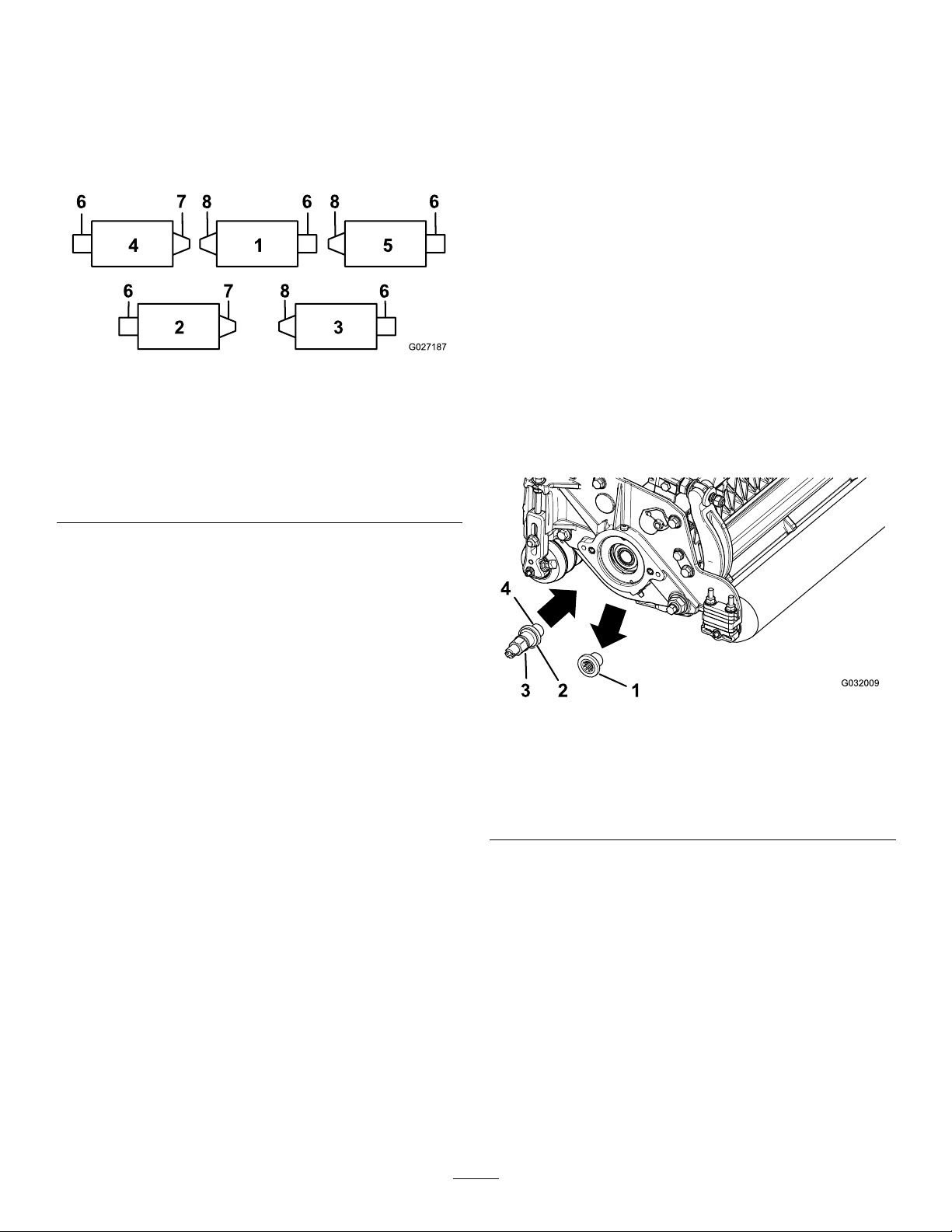
DeterminingtheRoller
BrushOrientation
Allcuttingunitsareshippedwiththecounterweight
mountedtotheleftendofthecuttingunit.Referto
Figure1todeterminethepositionoftherollerbrush
andreelmotors.
InstallingtheRollerBrush
InstallingtheDriveshaft
1.Parkthemachineonalevelsurfaceandsetthe
parkingbrake.
2.Ensurethatthecuttingunitsaredisengaged.
3.Shuttheengineoffandremovethekey .
4.Removeallthecuttingunitsfromthemachine.
Important:Checkthecuttingunitforthe
desiredheightofcutandattitude.Make
adjustmentspertheOperator’sManual,if
required,beforeinstallingthekit.
Figure1
1.Cuttingunit15.Cuttingunit5
2.Cuttingunit2
3.Cuttingunit3
4.Cuttingunit48.Leftroller-brushdrive
6.Reelmotor
7.Rightroller-brushdrive
assembly
assembly
Note:Theseinstructionsandillustrationsshowthe
installationofthekitoncuttingunitswiththeend
weightsmountedontheleftendofthecuttingunit.
g027187
5.Restrainthereelforremoval;refertoRestraining
theReelforRemovingThreadedInserts(page
10).
6.Removethecutting-unitthreadedinsertforthe
rear-roller-brushdrive(Figure1)anddiscardit
(Figure2).
g032009
Figure2
1.Threadedinsert
(left-handedinsertshown)
2.Theleft-handinserthasa
grooveonthefaceofthe
inserthere.
3.Driveshaft
4.Applythread-locking
compoundhere.
Note:Left-handedinsertsareoncuttingunits
1,3,and5(Figure1).
7.Restrainthereelforinstallation;referto
RestrainingtheReelforInstallingThreaded
Inserts(page11).
8.Applythread-lockingcompoundtothedriveshaft
threads(Figure2)andinstallthedriveshaft,
torquingitto1 15to128N·m(85to95ft-lb).
2
Page 3
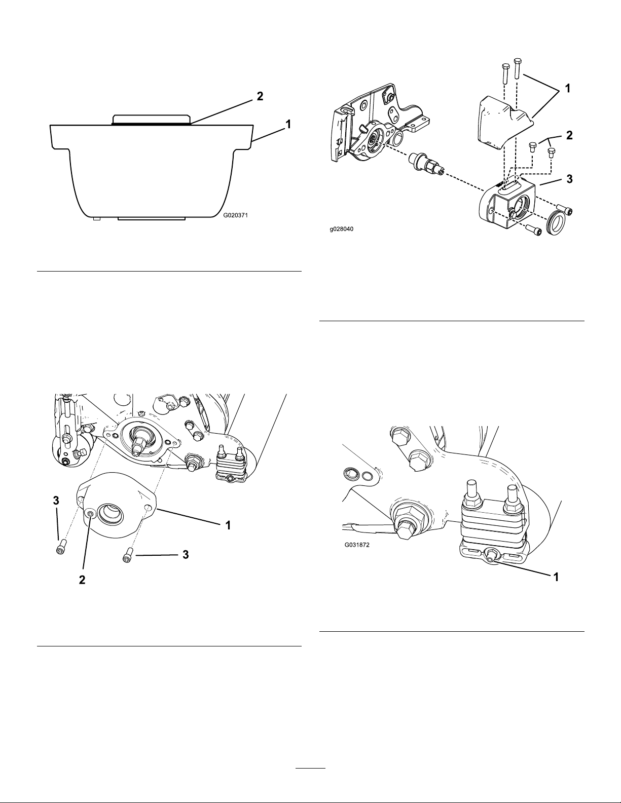
MountingtheRoller-Brush
Housing
1.EnsurethattheO-ringisinstalledonthe
roller-brushhousing(Figure3).
Figure3
1.Roller-brushhousing
2.ForModel03408only:Mounttheroller-brush
housingtothereel-bearinghousingwith2
hex-socketbolts(3/8x1inch);refertoFigure4.
2.O-ring
housingwith2bolts(5/16-18x11/2inches);
refertoFigure5.
g020371
g028040
Figure5
1.End-weightkit(Model
03413,electricreelmotor)
2.Bolts(5/16-18x1/2inch),
hydraulicreelmotor
3.Roller-brushhousing
Note:Positiontheroller-brushhousingsothat
thethreadedholeistowardthefrontofthe
cuttingunit.
Note:EnsurethattheO-ringisproperly
positionedintheroller-brushhousing.
Figure4
1.Roller-brushhousing3.Hex-socketbolt
2.Threadedhole
3.ForModel03406kitwithRM5010tractorswith
thefollowing:
•Hydraulic5-inchreelmotors,install2
bolts(5/16-18x1/2inches)ontopofthe
roller-brushhousing(Figure5).
•Electric5-inchreelmotors,installthe
end-weightkitontopoftheroller-brush
InstallingtheRollerBrush
Assembly
1.Removethegreasettingfortherollerfromthe
sideofthecuttingunitthathastheroller-brush
housing(Figure7).
g221538
1.Greasetting
Figure6
2.Installthe90-degreegreasettingsothatit
facesbackward(Figure6).
g031872
3
Page 4
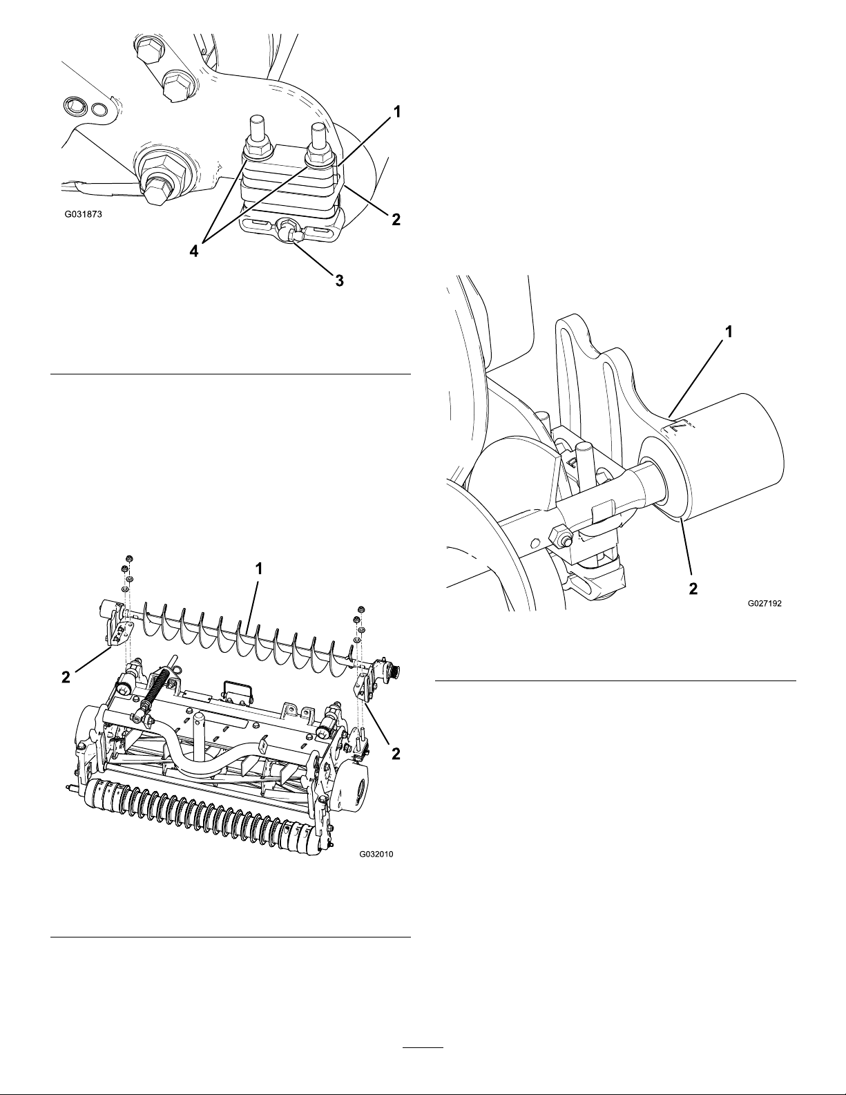
Figure7
1.6mm(1/4inch)spacer3.90-degreegreasetting
2.Side-platemountingange4.Flangelocknuts(remove)
3.Removethe2angelocknutssecuringeach
rollerbrackettothesideplates(Figure7).
Note:Donotremovethebolts.Also,remove
any6mm(1/4inch)spacerspositioned
onthetopsideoftheside-platemounting
ange.
4.Positiontheleftorrightroller-brushassembly
mountingbracketsontotheroller-bracketbolts
(Figure8).
roller-brushmountingbracketsandthe
side-platemountinganges.Savethe
additional6mm(1/4inch)spacersfor
potentiallateruse.
5.Securethebrush-assemblymountingbrackets
tothecutting-unitsideplateswiththenuts
previouslyremoved.
InstallingtheRollerBrushPlate
1.Slideeachexcludersealoutwarduntilthelip
sealsareinlightcontactwitheachbearing
housing(Figure9).
g031873
Figure8
1.Leftroller-brushassembly
2.Roller-brushmounting
bracket
Important:Mounttheroller-brushassembly
mountingbracketsdirectlytothetopsurface
ofthecutting-unitside-platemounting
ange.Donotputspacersbetweenthe
g027192
Figure9
1.Bearinghousing2.Excluderseal
2.Applyacoatingofgreasetotheinnerdiameter
ofthegrommetintheroller-brushhousing
(Figure10).
g032010
4
Page 5

Figure10
Note:Theshoulderboltshouldnotclampthe
platetothehousing.
8.Checktoensurethattheroller-brushplateis
paralleltothecutting-unitsideplate.Ifitisnot
parallel,proceedasfollows:
A.Loosenthe2angelocknutssecuring
theroller-brushmountingbrackettothe
cutting-unitsideplate(Figure1 1).
B.Rotatetheroller-brushbearinghousinguntil
thebrushplateisparalleltothecutting-unit
sideplate(Figure11).
C.Tightenthe2angelocknutssecuring
g218675
theroller-brushmountingbrackettothe
cutting-unitsideplate(Figure1 1).
1.Bolt
2.Shoulderbolt
3.Grommet
4.Cleanoutanypaint
fromthethreadsusing
a5/16–18tapbefore
screwingintheshoulder
bolt.
5.Roller-brushhousing
6.Roller-brushpivotplate
assembly
3.Installtheleftorrightroller-brushpivotplate
(Figure10).
Note:Whenyouinserttheprotrusiononthe
pivotplateintothegrommetintheroller-brush
housing,ensurethatthegrommetstaysproperly
seatedinthehousing.Theroller-brushpivot
plateisproperlyseatedwhenthereisno
resistancefromtherubbergrommetanditpivots
freely.
Note:Ensurethattheidler-pulleyassemblyis
installedonthebottomasshowninFigure10.
4.Applythread-lockingcompoundtothe2bolts
(5/16x1/2inch)andusethemtomountthe
brushplatetotheroller-brushbearinghousing
(Figure10).
g027194
Figure11
1.Loosentheseboltsforpositioningtherollerbrush.
2.Loosenthesenutsformakingtheroller-brushplateparallel.
Note:Torquetheboltsto20to25N·m(15to
19ft-lb).
5.Cleanoutanypaintfromthethreadsinthe
roller-brushhousing,usinga5/16–18tap,before
screwingintheshoulderbolt(Figure10).
Important:Ifthethreadsarenotcleaned
beforetheshoulderboltisscrewedin,the
boltcouldbreak.
6.Applythread-lockingcompoundtotheshoulder
bolt(Figure10).
7.Securethebrushplatetotheroller-brush
housingwiththeshoulderbolt(Figure10).
Note:T orquetheboltto20to25N·m(15to
19ft-lb).
PositioningtheRollerBrush
1.Loosenthe2boltssecuringeachroller-brush
bearinghousingtotheroller-brushmounting
bracket(Figure11).
Note:Theboltsshouldbeloosefromthe
factory.
2.Positiontherollerbrushsothatitisjusttouching
orrestingontherearroller(Figure12).
Important:Theroller-brushshaftmustnot
contactthecutting-unitsideplate.
Important:Heavybrushcontactonthe
rollerwillcauseprematurebrushwear.
5
Page 6

Important:Iftheboltisnotproperly
torqued,theboltwillcomeloose.
Figure13
g027195
Figure12
1.Bearinghousing(some
partsnotshown)
2.Sideplate
3.Rollerbrush
4.Ensurethatthereis
clearancehere.
5.Lightcontact
6.Rearroller
7.Greasetting
Note:Theroller-brushshaftmustbeparallel
totherearroller.
Important:Positionbothroller-brush
bearinghousingssothattheyareparallel
tothegroundtoensureclearanceforthe
rear-rollergreasetting.
3.Tightenthe2boltssecuringeachroller-brush
bearinghousingtotheroller-brushmounting
brackets.
1.Driveshaft
2.Spacer
g027303
3.Drivepulley
4.Flange-headbolt—torque
to47to54N·m(35to40
ft-lb)
InstallingtheBelt
1.Installthebeltontothepulleysasfollows:
•Loopthebeltaroundthedrivepulleyand
thenoverthetopoftheidlerpulley(Figure
14).
InstallingtheDrivePulley
1.Insertthespacerontotheshaftinthebearing
housing(Figure13).
2.Insertthedrivepulleyintothespacerandonto
thedriveshaft(Figure13).
Note:Ensurethatthepulleytabsarepositioned
intheslotinthedriveshaft.
3.Securethepulleyandspacertothedriveshaft
withaange-headbolt(3/8x2inches);refer
toFigure13.
Note:Torquetheboltto47to54N·m(35to
40ft-lb).
g027196
Figure14
1.Drivepulley3.Belt
2.Idler-pulleyassembly4.Drivenpulley
•Startthebeltonthedrivenpulley(Figure
15).
•Usea9/16-inchdeep-wellsockettorotate
thebrushassemblyandguidethebeltonto
thedrivenpulley(Figure15).
6
Page 7

Figure15
g027197
Figure16
2.Slidethebeltcoverontothemountingboltsand
securethecoverwith2angenuts(Figure17).
Important:Donotovertightenthenutsas
damagetothecovermayoccur.
g020390
1.Belt
2.9/16-inchdeep-wellsocket
Important:Ensurethattheribsonthebelt
areproperlyseatedinthegroovesineach
pulleyandthatthebeltisinthecenterofthe
idlerpulley .
2.Pushdownontheidlerpulleytoensurethatthe
idler-pulleyassemblypivotsfreely.
CompletingtheInstallation
1.Checkthealignmentofthebeltandpulleysas
follows:
•Thebeltmustbeproperlytensioned
(installed)priortocheckingthealignment.
•Layastraightedgealongtheouterfaceof
thedrivepulley(Figure16).Donotlaythe
straightedgeacrossboththedrivepulleyand
thedrivenpulley.
•Theouterfacesofthedrivepulleyandthe
drivenpulleyshouldbeinlinewithin0.76
mm(0.030inch).
•Ifthepulleysarenotaligned,referto
CheckingthePulleyAlignment(page9).
•Ifthepulleysarealigned,continuewiththe
installation.
•Donotusetheidlerpulleytocheckthe
alignment.
Important:Thebeltmayfailprematurely
ifthepulleysarenotproperlyaligned.
g027198
Figure17
1.Beltcover
2.Setscrewinstalled
3.Setscrewremoved
3.Lubricatethegreasettingsoneachofthe
roller-brushbearinghousingswithNo.2lithium
grease(Figure18).Wipeoffanyexcessgrease,
especiallyaroundtheexcluderseals.
g032011
Figure18
7
Page 8

InstallingtheHigh
Height-of-CutBrush
(Optional)
Installthehighheight-of-cutbrush(soldseparately)
whentheheightofcutis2.5cm(1inch)ormore(5or
morespacersinstalledbelowthesideplatepad).
1.Ifarollerbrushisinstalledonthecutting
unit,removethe2bolts,washers,andnuts
securingthenon-drivebearinghousingtothe
bearing-housingmountingbracket(Figure19
andFigure20).
7.Clampthebrushontotheshaftwiththe2J-bolts
andnutspreviouslyremoved(Figure21).
Important:Insertthethreadedendofthe
J-boltsthroughtheouterholesofthebrush
shaftwhilehookingthecurvedendsofthe
J-boltsintotheinnerholes.
8.TorquetheJ-boltlocknutsto2to3N·m(20to
25in-lb).
Figure19
1.Non-drivebearinghousing
2.Slidethenon-drivebearinghousingandthe
excludersealoffthebrushshaft(Figure20).
Figure20
1.Non-drivebearinghousing
2.Excluderseal
3.Removethe2J-boltsandthenuts(Figure21).
4.Slidetheexistingbrushoffthebrushshaft
(Figure21).
5.Loosenthe2bolts,washers,andnutssecuring
thedrive-bearinghousingtothebearing-housing
mountingbracket(Figure21).
6.Slidethehighheight-of-cutbrushontothebrush
shaft(Figure21).
3.Brushshaft
g027200
g027202
Figure21
1.Highheight-of-cutbrush
2.J-bolts
9.Installtheexcludersealandthenon-drive
bearinghousingontothebrushshaft(Figure20).
10.Mountthenon-drivebearinghousingtothe
bearing-housingmountingbracketwiththe2
bolts,washers,andnutspreviouslyremoved.
3.Loosenthesebolts.
Note:Becarefulnottoknockthesealspring
off.
11.Tightenthe2bolts,washers,andnutssecuring
thedrive-bearinghousingtothebearing-housing
g027201
mountingbracket.
InstallingtheEndWeight
KitfortheReelmaster
5010-Hwith5-inchCutting
Units
Note:Theendweightkitisonlyrequiredforthe
Reelmaster5010–Hwith5-inchcuttingunits.
RefertotheInstallationInstructionsfortheweightkit.
8
Page 9

Maintenance
5.Ifthepulleyneedstomoveout,adda0.8mm
(0.032inch)thickwasher(Figure23).
•Ensurethatthebrushisparalleltotherollerwith
1.5mm(0.060inch)clearancetolightcontact.
•Greasethettingsevery50hoursandafterevery
washing.
•Whenreplacingarollerbrush,torquetheJ-bolts
to2to3N·m(20to25in-lb).
•Whenreplacingthebrush-shaft-drivenpulley,
torquethenutto36to45N·m(27to33ft-lb).
•Whenreplacingthebrush-drivepulley,apply242
Loctite(blue)andtorquetheboltto47to54N·m
(35to40ft-lb).
Note:Therollerbrush,theidlerbearing,andthebelt
areconsideredconsumableitems.
CheckingthePulley
Alignment
1.Thedrivenpulley(attheroller-brushshaft)can
moveinorout(Figure22).
Note:Makenoteofwhichwaythepulleyneeds
tomove.
Note:Ifthepulleyneedstomovein,remove
theexisting0.8mm(0.032inch)thickwasher.
6.Installthepulley.
Figure23
1.Locknut
2.Drivenpulley
7.Whileholdingthebrush-shaftats,securethe
drivenpulleyontheshaftwiththe3/8-16ange
nutpreviouslyremoved.
3.Washer—0.8mm(0.032
inch)thick
4.Brush-shaftats
g009077
Figure22
1.Drivenpulley3.Driven-pulleynut
2.Idlerpulleyassembly
2.Whilerotatingthereel,whichrotatesthedrive
pulley,prythebeltoffthedrivepulley(Figure22
Note:Wearapaddedgloveoruseaheavyrag
torotatethereel.
3.Removethelocknutsecuringthedrivenpulley
tothebrushshaft(Figure22orFigure23).
Note:Usea1/2-inchwrenchontheroller-brush
shaftatstokeepitfromrotating.
4.Removethedrivenpulleyfromtheshaft(Figure
23).
Note:Seatthelocknut;thentorqueitto36to
45N·m(27to33ft-lb).
8.Installthebeltontothepulleysasfollows:
A.Loopthebeltaroundthedrivepulleyand
thenoverthetopoftheidlerpulley(Figure
24).
g020303
g031875
Figure24
1.Drivenpulley3.Drivepulley
2.Idler-pulleyassembly4.Belt
B.Startthebeltonthedrivenpulley(Figure
24).
C.Usea9/16-inchdeep-wellsockettorotate
thebrushassemblyandguidethebeltonto
thedrivenpulley(Figure25).
9
Page 10

Figure25
3.Placetheprybaragainsttheweldsideofthe
reelsupportplate(Figure26).
Note:Inserttheprybarbetweenthetopofthe
reelshaftandthebacksof2reelbladessothat
thereelwillnotmove.
Important:Donotcontactthecuttingedge
ofanybladeswiththeprybar;thismay
damagethecuttingedgeand/orcauseahigh
blade.
Important:Theinsertontheleftsideof
thecuttingunithasleft-handthreads.The
insertontherightsideofthecuttingunithas
right-handthreads.
g020390
1.Belt
2.9/16-inchdeep-wellsocket
Important:Ensurethattheribsonthebelt
areproperlyseatedinthegroovesineach
pulleyandthatthebeltisinthecenterofthe
idlerpulley .
9.Checkthepulleyalignmentandadjustitif
necessary.
RestrainingtheReel
WARNING
Thecuttingreelbladesaresharpandcapable
ofamputatinghandsandfeet.
•Keepyourhandsandfeetoutsideofthe
reel.
•Ensurethatthereelisrestrainedbefore
servicingit.
RestrainingtheReelforRemoving
Figure26
1.Threadedinsertfor
removal
2.Loosentheshieldbolt.5.Reelsupportplate
3.Rearshield6.Prybarinsertedalong
4.Reelshaft
theweldsideofthereel
supportplate.
4.Restthehandleoftheprybaragainsttherear
roller.
5.Completetheremovalofthethreadedinsert
whileensuringthattheprybarstaysinplace,
thenremovetheprybar.
6.Lowertherearshieldandtightentheshield-bolt.
g280383
ThreadedInserts
1.Loosentheshield-boltontheleftsideofthe
cuttingunitandraisetherearshield(Figure26).
2.Insertalong-handledprybar(recommended
3/8"x12"withscrewdriverhandle)throughthe
backofthecuttingreel,closesttothesideofthe
cuttingunitthatyouwillbetorquing(Figure26).
10
Page 11

RestrainingtheReelforInstalling
ThreadedInserts
1.Insertalong-handledprybar(recommended
3/8"x12"withscrewdriverhandle)throughthe
frontofthecuttingreel,closesttothesideofthe
cuttingunitthatyouwillbetorquing(Figure27).
2.Placetheprybaragainsttheweldsideofthe
internalcuttingreelreinforcement(Figure27).
Note:Theprybarshouldcontactabladeatthe
front,thereelshaft,andabladeatthebackof
thebackofthereel,lockingitinplace.
Important:Donotcontactthecuttingedge
ofanybladeswiththeprybar;thismay
damagethecuttingedgeand/orcauseahigh
blade.
Important:Theinsertontheleftsideof
thecuttingunithasleft-handthreads.The
insertontherightsideofthecuttingunithas
right-handthreads.
Figure27
1.Threadedinsertfor
installation
2.Reelshaft
3.Weldsideofsupportplate
4.Prybar
3.Restthehandleoftheprybaragainsttheroller
4.Pertheinsert’sinstallationinstructionsand
torquerequirements,completetheinstallationof
thethreadedinsertwhileensuringthatthepry
barstaysinplace,thenremovetheprybar.
g280384
11
Page 12

DeclarationofIncorporation
TheT oroCompany,8111LyndaleAve.South,Bloomington,MN,USAdeclaresthatthefollowingunit(s)
conform(s)tothedirectiveslisted,wheninstalledinaccordancewiththeaccompanyinginstructionsontocertain
ToromodelsasindicatedontherelevantDeclarationsofConformity.
ModelNo.
SerialNo.
03406
03408
—
—
ProductDescriptionInvoiceDescription
RearRollerBrushKit,
Reelmaster5010-HSeries
CuttingUnitwith5inReel
RearRollerBrushKit,
Reelmaster5010-HSeries
CuttingUnitwith7inReel
RRBONL YKIT5INCU
[RM5010]
RRBONL YKIT7INCU
[RM5010]
GeneralDescription
RollerBrushKit
RollerBrushKit
Directive
2006/42/EC
2006/42/EC
RelevanttechnicaldocumentationhasbeencompiledasrequiredperPartBofAnnexVIIof2006/42/EC.
Wewillundertaketotransmit,inresponsetorequestsbynationalauthorities,relevantinformationonthispartly
completedmachinery.Themethodoftransmissionshallbeelectronictransmittal.
ThismachineryshallnotbeputintoserviceuntilincorporatedintoapprovedT oromodelsasindicatedonthe
associatedDeclarationofConformityandinaccordancewithallinstructions,wherebyitcanbedeclaredin
conformitywithallrelevantDirectives.
Certied:
JohnHeckel
Sr.EngineeringManager
811 1LyndaleAve.South
Bloomington,MN55420,USA
February1,2019
AuthorizedRepresentative:
MarcelDutrieux
ManagerEuropeanProductIntegrity
ToroEuropeNV
Nijverheidsstraat5
2260Oevel
Belgium
 Loading...