

Page 1
Introduction
Adding a RainSensor or RainSensor + Freeze
to your automatic sprinkler system is an
effective means of conserving water and
lowering your monthly water bill, while
promoting a healthier lawn and garden.
Designed for ease of installation, your sensorcontrolled irrigation system will be up and
running in minutes.
Prior to installing the RainSensor, take a few
moments to read through the instructions in
their entirety. Since the RainSensor is designed
to work with most makes and models of
automatic sprinkler timers, you should also refer
to the instructions provided with your timer for
specific information regarding the connection
and use of a rain sensor or rain switch.
Important:
The RainSensor is rated for 24 VAC power only. Connecting to a higher
voltage may result in severe equipment damage.
Installation methods must comply with all applicable national and local
electrical codes. If you are unsure about proper wiring practices, have a
qualified contractor perform the installation for you.
The RainSensor must not be submerged. Do not install the sensor inside a
rain gutter or any location where water can accumulate.
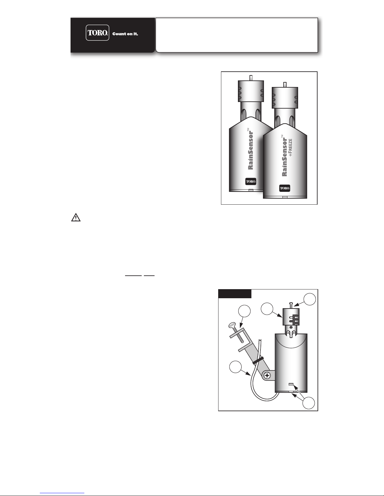
RainSensor Components
1 - Test Spindle - Pressed to manually test
RainSensor operation.
2 - Rainfall Adjustment Cap - Adjusts
RainSensor sensitivity from 3mm to 25mm
of detected rainfall.
3 - Quick-Clip
TM
- Universal mounting bracket
for easy installation.
4 - Connection Cable - 25ft (7.6m) of connec-
tion cable included.
5 - Access Cover - Easily removed for access
to internal components.
Wired RainSensor
TM
- Model 53769
RainSensorTM + Freeze - Model 53853
Installation Guide
1
2
3
4
Figure 1
5
Page 2
Installation Procedure
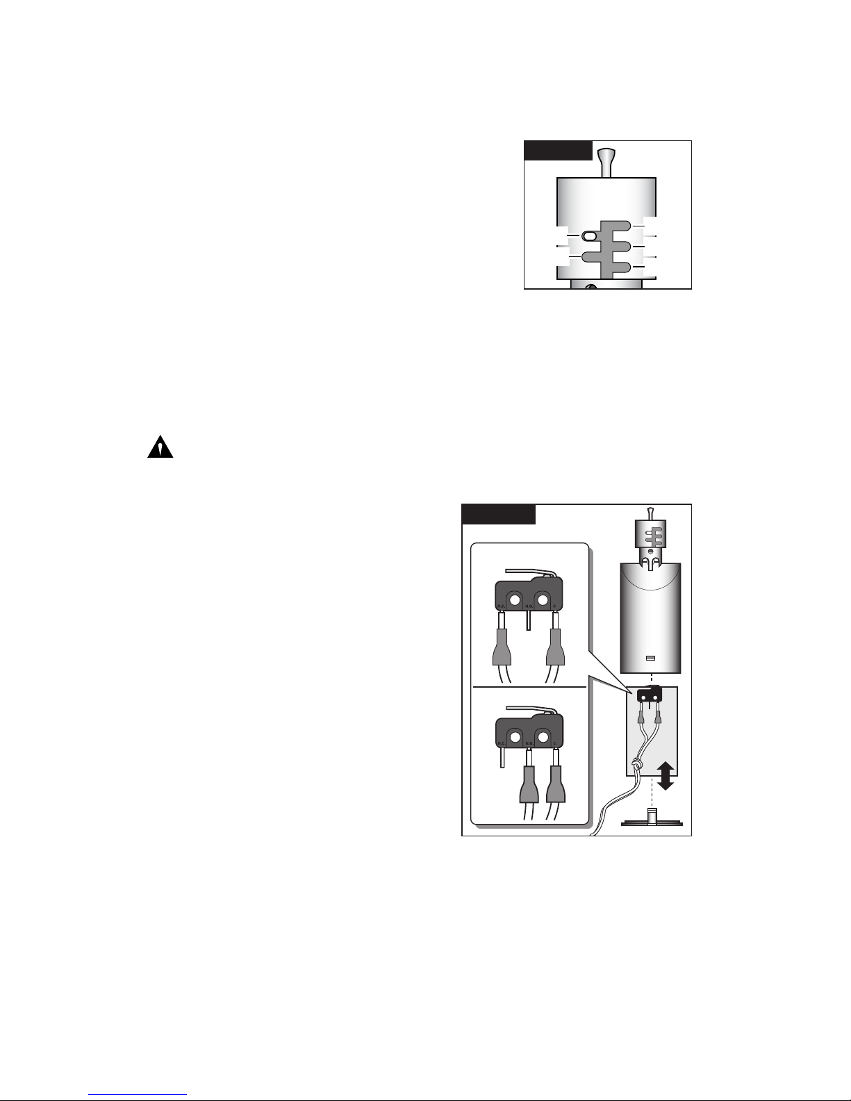
v Adjust Rain Sensitivity: The sensitivity setting determines the amount of
rainfall required to trigger the RainSensor and suspend automatic watering.
The RainSensor is factory-set at 6mm. Prior to installing the RainSensor, adjust
the rainfall sensitivity as preferred to one of four optional settings as indicated in
Figure 2.
To adjust, turn the cap slightly to disengage the pins
from the current setting. Adjust the cap up or down to
the preferred slot position, then re-engage the pins.
Note: Make sure the slot is correctly aligned with the pin
when making an adjustment. Do not force the cap into
position.
Note: The 3mm setting is not recommended for locations where high-humidity is common.
v Set Sensor Operation Mode (Applies to Model 53769, RainSensor Only):
The RainSensor is preset for normally-closed sensor operation, but can be
easily converted to normally-open if needed. Prior to installation, determine
whether your automatic timer requires a normally-closed or normally-open sensor by referring to the timer user’s guide. If a normally-open sensor is required
(for example, when used with a Toro ECxTM or GreenKeeper
®
timer), configure
the RainSensor as shown in Figure 3.
Model 53853 only: If using the Freeze version, model 53853, and your
controller requires Normally Open Sensor operation, the sensor connection can
not be used. Instead, refer to the wiring configuration B and C under “Connect
RainSensor Wiring” section.
1. Using a small screwdriver, release and
remove the access cover by depressing
the two retaining tabs. Slide the control
board assembly out of the housing.
See Figure 3.
2. Carefully remove the wire connector from
the left pin of the microswitch and attach it
to the center pin. Leave the right wire
connected.
3. Slide the control board back into the
housing making sure it is properly aligned.
Install the access cover with the connection
wire knot on the inside the housing.
6mm
13mm
25mm
19mm
3mm
Figure 2
Normally Open
Normally Closed
Figure 3
Page 3
v Select the Installation Site:
To operate properly, the RainSensor must be installed in an outdoor location
that provides the following conditions:
• As close to the timer as possible. If the connection wire will not reach the timer, it
can be extended to 100ft (30m) using 18 AWG (1.0mm2) insulated wire.
• Exposed to unobstructed sunlight and rainfall.
• Shielded from irrigation spray and rainwater runoff.
• Model 53853 only – Locate the RainSensor + Freeze model in the coolest por-
tion of the watered area. A northeast to northwest exposure is preferable. Avoid
installation near a heat source, such as a chimney or dryer vent.
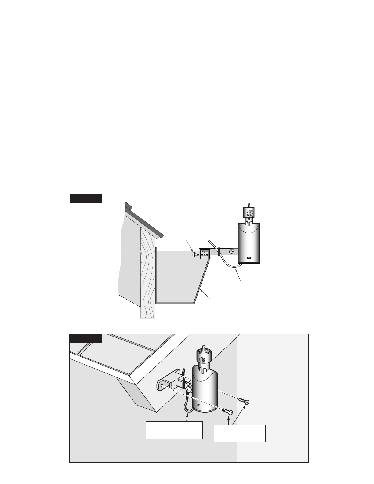
v Install the RainSensor
A rain gutter is an ideal location for the RainSensor. Simply position the bracket
with the thumbscrew under the top lip of the rain gutter and tighten to secure (do
not over-tighten). See Figure 4.
The RainSensor can also be mounted on any suitable solid structure such as
the side of the roof, a shed, or fence using the two supplied stainless steel
screws. See Figure 5 below.
Once securely fastened, adjust the RainSensor on the mounting bracket to align
the housing vertically.
Rain Gutter
Connection Wire
To Controller
Figure 4
Thumbscrew
Figure 5
Stainless Steel
Screws
Connection Wire
To Controller
Page 4
v Connect RainSensor Wiring:
Route the RainSensor connection wire into the timer through the access hole in
the base of the timer cabinet.
Note: Avoid routing the wire over any sharp edges where damage to the wire
insulation may occur. For best results, hide the wire as much as possible by
tucking it under shingles and/or moldings. Seal any holes made by passing the
wire through structure walls.
Caution: To prevent severe equipment damage, never connect the
RainSensor to any power source greater than 24 VAC. If you are in doubt,
contact a qualified installer or electrician.
1. Disconnect power to the timer.
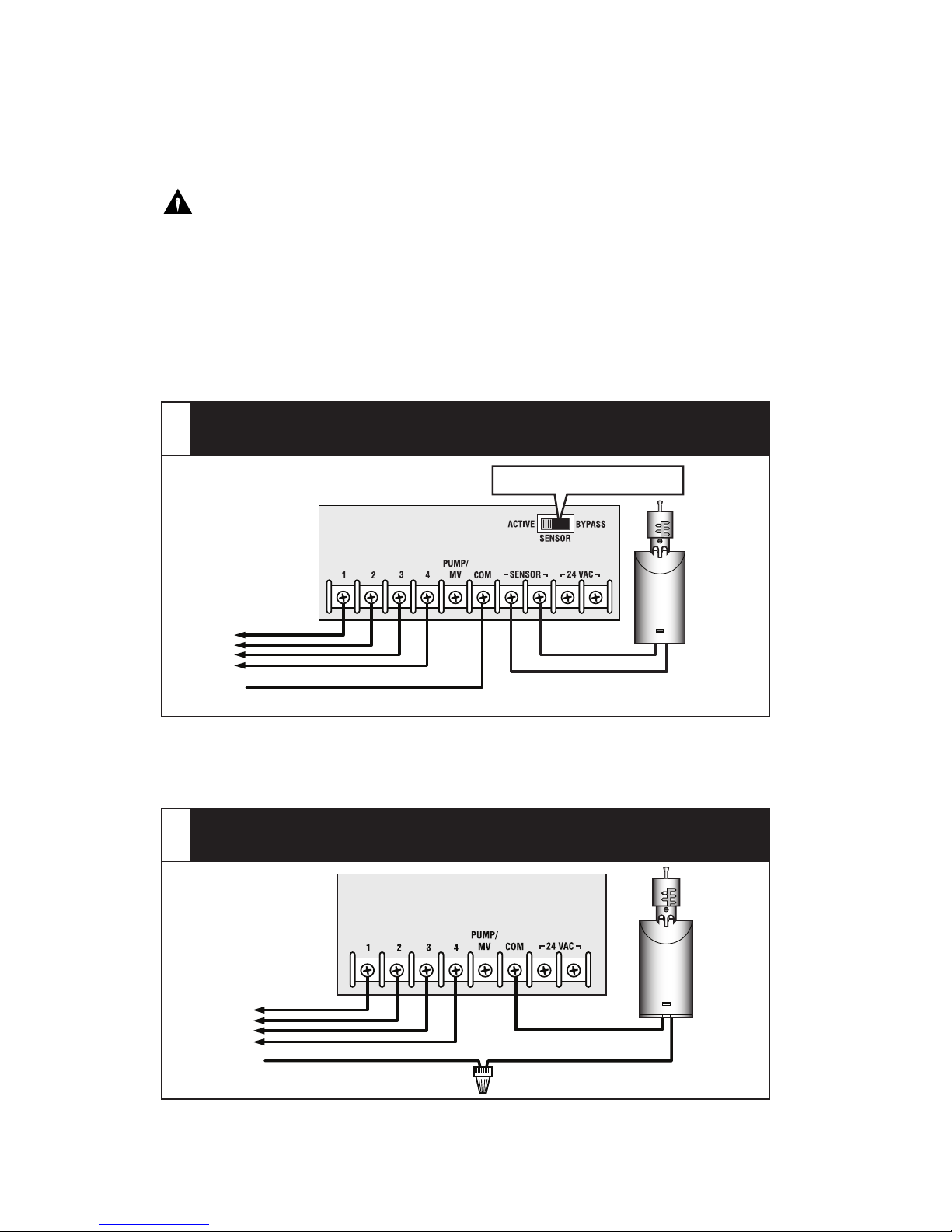
2. Use one of the following connection methods A, B or C, that best suits the
timer model configuration.
• Find the controller sensor terminals (generally marked “SENSOR”, “SEN”
or “S”) and attach the RainSensor control wires directly to these terminals
(in either order).
Note: There may be a jumper wire connecting the two Sensor wire terminals
that must be removed when connecting the RainSensor. Also, place the Sensor
Bypass switch in the Active position for sensor-controlled operation.
• Remove the valve common wire(s) from the valve common wire terminal and
join to one RainSensor wire lead using a twist-on wire connector. Attach the
remaining RainSensor wire lead to the valve common terminal.
Common Wire From Valves
Timer with Sensor terminals, with or without pump start/
master valve:
A
Sensor Bypass Switch
Common Wire From Valves
To Valves
Twist-on Wire Connector
Irrigation System Timer
Timer without Sensor terminals or pump start/ master
valve:
B
To Valves
Page 5

• Remove all common wires from the common terminal(s) and join to one
RainSensor wire lead using a twist-on wire connector. (Be sure to include the
common wire from the pump start relay or master valve in this connection).
Attach the remaining RainSensor wire lead to the valve common terminal.
Testing the RainSensor Installation
To test the RainSensor operation, turn on a watering zone visible from the
RainSensor location. Press and hold down the Test Spindle; watering should
stop within a short time. If watering does not stop, recheck the wiring connections at the timer. If the timer has a Sensor Bypass switch, make sure the switch
is set to Active.
Note: The installation and operation of a freeze sensor should be used
in conjunction with frequent visual checks of your sprinkler system. While
freeze sensors are designed to prevent inadvertent watering during near
or below freezing conditions, there are instances in which manual intervention is required. Air temperatures may be above freezing while ground and
vegetation temperatures remain below freezing. Operation of your sprinkler
system during these conditions may cause icing. Very rapid air temperature changes may also result in inadvertent watering, should the timing of
sprinkling coincide with rapid temperature changes. The Sensor should be
inspected for damage and manually tested regularly to ensure proper
operation.
Caution: Visual checks and prudent manual watering suspension
must be used in conjunction with any freeze sensor.
A freeze sensor should only be relied upon as an aid along with good
watering practices including frequent visual checks. This device is not
intended for farm/crop protection.
Common Wire From Valves
To Valves
Pump Start
Relay/Master
Valve
Irrigation System Timer
Timer without Sensor terminals, with pump start/master
valve:
C
Twist-on Wire Connector
Page 6

RainSensor Operation
v Automatic Operation
When the RainSensor activates due to sufficient rainfall (or freezing conditions
- model 53853 only), watering will be terminated until the RainSensor automatically resets. The reset rate will vary depending on temperature, solar radiation,
humidity and wind—the same conditions exposed to your landscape.
v Bypass Operation
To bypass RainSensor operation, place the timer’s sensor switch in the Bypass
position, or temporarily remove the RainSensor from the valve common wire circuit.
Model 53853 only: The freeze sensor is designed to terminate automatic watering when air temperature reaches approximately 3°C (37°F)
+/- 2°C. Once freezing has occurred, the air temperature can increase
above the sensor trigger point, while the ground temperature remains at
or below freezing – resulting in icing conditions. Additionally, watering
can occur if the automatic watering schedule coincides with a very rapid
decrease in temperature.
Specifications
Mounting: Quick-ClipTM rain gutter bracket or screws (2 provided)
Connection Wire: 25ft (7.6m) –1.0mm2 insulated 2-lead cable, UL-approved
Sensor Type: Industry-standard hygroscopic disc stack with adjustable
rainfall sensitivity
Switch Rating: 3A, 24 VAC, Normally Open/Normally Closed
Operating Temperature Range: -29°C to 60°C
Model 53853 Rain+Freeze only: Freeze set point of 3°C (37°F) +/- 2°C.
Material: Stainless steel and UV-resistant engineered polymer
The Toro Promise — Limited One-Year Warranty
The Toro Company and its affiliate, Toro Warranty Company, pursuant to an agreement between
them, jointly warrants, to the owner against defects in material and workmanship for a period of one
year from the date of purchase.
Neither The Toro Company nor Toro Warranty Company is liable for failure of products not manufactured by them even though such products may be sold or used in conjunction with Toro products.
During such warranty period, we will repair or replace, at our option, any part found to be defective.
Return the defective part to the place of purchase.
Our liability is limited solely to the replacement or repair of defective parts. There are no other
express warranties.
This warranty does not apply where equipment is used, or installation is performed, in any manner
contrary to Toro’s specifications and instructions, nor where equipment is altered or modified.
NEITHER THE TORO COMPANY NOR TORO WARRANTY COMPANY IS LIABLE FOR INDI-
RECT, INCIDENTAL OR CONSEQUENTIAL DAMAGES IN CONNECTION WITH THE USE OF
EQUIPMENT, INCLUDING BUT NOT LIMITED TO: VEGETATION LOSS, THE COST OF SUBSTITUTE EQUIPMENT OR SERVICES REQUIRED DURING PERIODS OF MALFUNCTION OR
RESULTING NON-USE, PROPERTY DAMAGE OR PERSONAL INJURY RESULTING FROM
INSTALLER’S NEGLIGENCE.
Some states do not allow the exclusion or limitation of incidental or consequential damages, so the
above limitation or exclusion may not apply to you.
ALL IMPLIED WARRANTIES, INCLUDING THOSE OF MERCHANTABILITY AND FITNESS FOR
USE, ARE LIMITED TO THE DURATION OF THIS EXPRESS WARRANTY.
Some states do not allow limitations of how long an implied warranty lasts, so the above limitation
may not apply to you.
This warranty gives you specific legal rights and you may have other rights which vary from state to
state.
© 2009 The Toro Company • www.toro.com • 1-800-367-8676 373-0542 Rev. B
Page 7

Introducción
La incorporación de un sensor de lluvia o de uno de
lluvia y helada en el sistema automático de riego por
aspersión contribuye de manera eficaz a ahorrar
agua y reducir los costos mensuales de riego,
además de ayudar a mantener el césped y el jardín
en un óptimo estado. El sistema de riego controlado
por sensor se ha diseñado para facilitar su
instalación y puede ponerse en funcionamiento en
cuestión de minutos.
Antes de instalar el sensor de lluvia, dedique unos
momentos para leer todas las instrucciones. Dado
que el sensor de lluvia se ha diseñado para funcionar
con la mayoría de las marcas y los modelos de
temporizadores de riego por aspersión automáticos,
le recomendamos que también consulte las
instrucciones que vienen con el temporizador, donde
encontrará información específica sobre la conexión
y el uso de un sensor de lluvia o un interruptor de desconexión por lluvia.
Importante:
El sensor de lluvia se ha diseñado para una fuente de alimentación de 24 VCA
exclusivamente. Si se lo conecta a un nivel de tensión superior, el equipo sufrirá
daños graves.
Es obligatorio que los métodos de instalación cumplan con toda la normativa
nacional y local aplicable sobre instalaciones eléctricas. Si tiene dudas acerca de
los procedimientos correctos de instalación eléctrica, contrate a un profesional
calificado para que realice la instalación.
El sensor de lluvia no debe sumergirse. No instale el sensor dentro de una
canaleta para agua de lluvia ni en ningún otro lugar donde pueda acumularse agua.
Componentes del sensor de lluvia
1 - Eje de prueba: se presiona para comprobar manualmente el funcionamiento del sensor
de lluvia.
2 - Tapa de ajuste de lluvia: ajusta la sensibilidad del sensor de 3 mm a 25 mm de lluvia
detectada.
3 - Quick-Clip™: soporte de montaje universidad que
facilita la instalación.
4 - Cable de conexión: se incluyen 7,6 m de cable
de conexión.
5 - Tapa de acceso: se retira con facilidad para
acceder a los componentes internos.
RainSensor™ con cables – RainSensor™
modelo 53769 + Helada – Modelo 53853
Guía de instalación
1
2
3
Figura 1
4
5
Page 8

Procedimiento de instalación
v Ajuste la sensibilidad a la lluvia: la configuración de la sensibilidad determina la
cantidad de lluvia necesaria para activar el sensor y suspender el riego automático.
El sensor viene ajustado de fábrica en 6 mm. Antes de instalar el sensor, ajuste la
sensibilidad a la lluvia en uno de los cuatro parámetros opcionales según se indica en la
figura 2.
Para realizar el ajuste, haga girar la tapa levemente a fin de
desenganchar los pasadores de la configuración actual. Ajuste
la tapa hacia arriba o hacia abajo en la posición de la ranura
preferida y vuelva a enganchar los pasadores.
Nota: Al realizar el ajuste, compruebe que la ranura quede
correctamente alineada con el pasador. No use fuerza para
colocar la tapa en su lugar.
Nota: No se recomienda usar el parámetro de 3 mm en
lugares donde, en general, hay mucha humedad.
v Configure el modo de funcionamiento del sensor (Aplica solo para sensor de
lluvia, modelo 53853): el sensor viene ajustado para su funcionamiento normalmente
cerrado pero, de ser necesario, se lo puede convertir con facilidad en normalmente
abierto. Antes de la instalación, consulte la guía del usuario del temporizador para
determinar si el temporizador automático necesita un sensor normalmente cerrado o
normalmente abierto. Si es necesario un sensor normalmente abierto (por ejemplo,
cuando se lo utiliza con un temporizador Toro ECx™ o GreenKeeper®), configure el
sensor Cuando mostrado en la figura 3.
1. Con la ayuda de un pequeño desatornillador,
presione las dos lengüetas de sujeción para
liberar y retirar la tapa de acceso. Deslice el
conjunto de la placa de control y retírelo del
alojamiento. Ver la figura 3.
2. Retire con sumo cuidado el conector de cable
del pasador izquierdo del microinterruptor y
conéctelo al pasador central. Deje el cable
derecho conectado.
3. Deslice la placa de control e introdúzcala en
el alojamiento, asegurándose de que quede
correctamente alineada. Instale la tapa de
acceso con el nudo del cable de conexión en la
parte interna del alojamiento.
6 mm
13 mm
25 mm
19 mm
3 mm
Figura 2
Normalmente abierto
Normalmente cerrado
Figura 3
Page 9

v Seleccione el lugar de instalación:
Para que el sensor funcione correctamente, debe instalarse en un lugar de exteriores
que reúna las siguientes condiciones:
• Encontrarse lo más cerca posible del temporizador. Si el cable de conexión no llega al
temporizador, se lo puede alargar hasta 30 m con un cable aislado de 1 mm2.
• Recibir la luz solar y la lluvia sin obstrucciones.
• Estar protegido del agua de riego y las escorrentías de agua de lluvia.
• Sólo el modelo 53853: Ubique el modelo de sensor de lluvia y helada en el sitio más
fresco de la zona de riego. Es preferible una exposición de noreste a noroeste. Evite
instalar el equipo cerca de una fuente de calor, como una chimenea o un orificio de
ventilación de un secador.
v Instale el sensor de lluvia
Una canaleta para agua de lluvia es el lugar ideal para instalar el sensor. Simplemente
posicione el soporte con el tornillo de mariposa debajo del borde superior de la canaleta y
ajuste el tornillo para fijarlo (no ajuste demasiado).
Ver la figura 4.
El sensor también puede instalarse en cualquier estructura sólida adecuada, como por
ejemplo el lateral del techo, un cobertizo o una cerca usando los dos tornillos de acero
inoxidable provistos. Ver la figura 5 a continuación.
Una vez fijado correctamente, ajuste el sensor en el soporte de montaje para alinear el
alojamiento verticalmente.
Canaleta para
agua de lluvia
Cable de conexión
al programador
Figura 4
Tornillo de mariposa
Figura 5
Tornillos de
acero inoxidable
Cable de conexión
al programador
Page 10

v Conecte los cables del sensor:
Introduzca el cable de conexión del sensor en el temporizador a través del orificio de
acceso de la base del gabinete del temporizador.
Nota: Evite pasar el cable por bordes filosos ya que puede dañarse el aislamiento del
cable. Para obtener resultados óptimos, oculte el cable lo más posible colocándolo
debajo de guijarros o molduras. Tape los orificios pasando el cable por las paredes
estructurales.
Atención: Para evitar que el equipo sufra daños graves, nunca conecte el sensor
a una fuente de alimentación de más de 24 VCA. Si tiene dudas, consulte a un
instalador o electricista calificado.
1. Desconecte el suministro eléctrico del temporizador.
2. Siga uno de los siguientes métodos de conexión A, B o C, utilizando el que mejor se
adapte a la configuración del modelo de temporizador.
• Localice los terminales del sensor del programador (en general, están marcados
“SENSOR”, “SEN” o “S”) y conecte los cables de control del sensor directamente a
estos terminales (en cualquier orden).
Nota: Es posible que un cable puente conecte los dos terminales del sensor que deben
quitarse al conectar el sensor de lluvia. Coloque el interruptor de anulación del sensor en
la posición de activo para el funcionamiento controlado por el sensor.
• Retire el cable o los cables comunes de la válvula de su terminal y conéctelo a uno
de los conductores del sensor con la ayuda de un conector de bloqueo por rotación.
Conecte el conductor restante al terminal común de la válvula.
Temporizador del
sistema de riego
Cable común de las válvulas
A las válvulas
Temporizador con terminales del sensor, con o sin arranque de
bomba/válvula maestra:
A
Interruptor de anulación del sensor
Cable común de las válvulas
A las válvulas
Conector de bloqueo por rotación
Temporizador del sistema de riego
Temporizador sin terminales del sensor o arranque de bomba/válvula
maestra:
B
Page 11

• Retire todos los cables comunes del terminal común y conéctelos a un conductor
del sensor con la ayuda de un conector de bloqueo por rotación. (Recuerde incluir el
cable común del relé de arranque de la bomba o la válvula maestra en esta conexión.)
Conecte el conductor restante al terminal común de la válvula.
Prueba de la instalación del sensor de lluvia
Para probar el funcionamiento del sensor, active una zona de riego que pueda verse
con facilidad desde la ubicación del sensor. Presione el eje de prueba y manténgalo
presionado, el riego debe detenerse en un breve tiempo. Si el riego no se detiene, revise
las conexiones de cables del temporizador. Si el temporizador cuenta con un interruptor
de anulación del sensor, compruebe que el interruptor esté en la posición de activo.
Nota: La instalación y la puesta en funcionamiento de un sensor de heladas debe
llevarse a cabo en combinación con controles visuales del sistema aspersor. Si bien
los sensores están diseñados para prevenir el riego involuntario en condiciones
cercanas o por debajo de heladas, hay casos en los que es necesario intervenir
manualmente. La temperatura del aire puede estar por encima de la helada
mientras que las temperaturas del suelo y la vegetación están por debajo de las
temperaturas de heladas. El funcionamiento de su sistema de riego en estas
condiciones puede propiciar la formación de hielo. Los cambios bruscos de la
temperatura del aire también pueden ocasionar riego involuntario, en caso de que
el horario de riego coincida con dichos cambios de temperatura.
Para asegurar su buen funcionamiento, es necesario inspeccionar el sensor para
encontrar posibles daños y probarlo regularmente de forma manual.
PRECAUCIÓN: Cualquier sensor de heladas debe utilizarse en
combinación con controles visuales y suspensión de riego manual.
Solamente es posible confiar en un sensor de heladas como una ayuda junto
con buenas prácticas de riego y controles visuales frecuentes. Este artefacto
no está destinado para la protección de granjas o cultivos.
Cable común de las válvulas
A las válvulas
Relé de arranque
de bomba/válvula
maestra
Temporizador del sistema de riego
Temporizador sin terminales del sensor, con arranque de
bomba/válvula maestra:
C
Conector de bloqueo por rotación
Page 12

Funcionamiento del sensor de lluvia
v Funcionamiento automático
Cuando el sensor se activa porque ha caído una cantidad suficiente de lluvia (o por
condiciones de helada - sólo el modelo 53853), el riego se interrumpe hasta que el
sensor se restablece automáticamente. La velocidad de restablecimiento variará según la
temperatura, la radiación solar, la humedad y el viento, es decir, las mismas condiciones
que afectan al espacio verde.
v Anulación del funcionamiento
Para anular el funcionamiento del sensor, coloque el interruptor del sensor del
temporizador en la posición de anulación "Bypass" o retire temporalmente el sensor del
circuito de cables comunes de la válvula.
Sólo el modelo 53853: El sensor de helada se ha diseñado para detener el
riego automático cuando la temperatura del aire alcanza los 3.0°C (37.5°F)
+/- 2°C
.
Una vez que haya tenido lugar la helada, la temperatura del aire puede aumentar
por encima del punto de activación del sensor, mientras que la temperatura
terrestre se mantiene al nivel de helada o por debajo de ésta, por lo que se
producen condiciones que generan hielo. Por otra parte, puede producirse el riego
si el programa de riego automático coincide con una disminución muy rápida de la
temperatura.
Especificaciones
Montaje: Soporte Quick-Clip™ de la canaleta para agua de lluvia o tornillos
(se suministran 2)
Cable de conexión: 7,6 m de cable aislado de 2 conductores de 1 mm2,
con homologación UL
Tipo de sensor: pila de disco higroscópico estándar de la industria con sensibilidad a la
lluvia ajustable
Especificación del interruptor: 3 A, 24 VCA, NO (abra normalmente) /
NC (normalmente cerrado)
Intervalo de temperaturas de operación: de -29°C a 60°C
Sólo el modelo 53853, para helada y lluvia: Helada punto fijo de 3°C +/- 2°C.
Material: acero inoxidable y polímero resistente a los rayos ultravioleta
La promesa de Toro – Garantía limitada de un año
The Toro Company y su afiliada, Toro Warranty Company, en virtud de un acuerdo entre sí, garantizan
conjuntamente este producto al propietario contra defectos de materiales o mano de obra durante un
periodo de un año a partir de la fecha de la compra .
Ni The Toro Company ni Toro Warranty Company son responsables de la falla de productos no fabricados
por ellos, aun cuando dichos productos se vendan o utilicen conjuntamente con productos Toro.
Durante el periodo de garantía, repararemos o sustituiremos a nuestra discreción cualquier pieza que
resulte ser defectuosa.
Devuelva la pieza defectuosa al lugar de la compra.
Nuestra responsabilidad se limita exclusivamente a la sustitución o la reparación de piezas defectuosas. No
existe ninguna otra garantía expresa.
Esta garantía no tendrá validez en los casos en que el equipo se use, o la instalación se haya realizado, de
una manera contraria a las especificaciones o instrucciones de Toro, así como tampoco si el equipo ha sido
alterado o modificado.
NI THE TORO COMPANY NI TORO WARRANTY COMPANY SON RESPONSABLES DE DAÑOS
INDIRECTOS, INCIDENTALES O CONSECUENTES RESPECTO AL USO DE LOS EQUIPOS,
INCLUYENDO PERO SIN LIMITARSE A: LA PÉRDIDA DE MASA VEGETAL, EL COSTO DE EQUIPOS
O SERVICIOS SUSTITUTORIOS NECESARIOS DURANTE PERIODOS DE AVERÍA O LA PÉRDIDA
CONSIGUIENTE DE USO, DAÑOS MATERIALES O LESIONES PERSONALES QUE SON EL
RESULTADO DE LA NEGLIGENCIA DEL INSTALADOR.
Algunos estados no permiten la exclusión de daños incidentales o consecuentes, y por tanto esta exclusión
puede no ser aplicable a usted.
CUALQUIER GARANTÍA IMPLÍCITA, INCLUYENDO LAS DE COMERCIABILIDAD Y APTITUD PARA UN
USO DETERMINADO, QUEDA LIMITADA A LA VIGENCIA DE ESTA GARANTÍA EXPRESA.
Algunos estados no permiten limitaciones a la vigencia de una garantía implícita, y por tanto esta exclusión
puede no ser aplicable en su caso.
Esta garantía le otorga derechos legítimos específicos, y es posible que usted tenga otros derechos que
varían de un estado a otro.
© 2009 The Toro Company • www.toro.com • 1-800-367-8676 373-0542 Rev. B
 Loading...