

Page 1

Part No. 111-3987 Rev A
R3240T 4WD WIDE AREA MOWER
Model No: 02770-Serial No. from 310000001
Operator’s Manual
Original Instructions (EN)
Date: 21.09.10
Page 2

Page 3
ATTENTION
THIS SYMBOL MEANS
BE ALERT!
YOUR SAFETY IS INVOLVED
READ THIS MANUAL BEFORE USING THE R3240T MOWER.
IT IS ESSENTIAL THAT OPERATORS STUDY IT FOR THEIR
OWN SAFETY.
ALL OPERATORS SHOULD SEEK AND OBTAIN PROFESSIONAL AND
PRACTICAL INSTRUCTIONS ON THE SAFE USE OF THE MOWER.
THESE SERVICES ARE AVAILABLE THROUGH TORO APPROVED
COMMERCIAL DEALERS.
Page 4

Page 5

1.5 1.5
CONTENTS Page No.
SAFETY PRECAUTIONS 1.7 - 1.17
Training 1.7
Preparation 1.8
Operation 1.9 - 1.10
Slopes 1.9
Handling and storage of uids 1.11
Maintenance and storage 1.12
Decals 1.13 - 1.18
EC CONFORMITY INFORMATION 1.19 - 1.20
Noise / Vibration levels 1.19
EC Declaration of Conformity 1.20
INTRODUCTION 1.21
SPECIFICATIONS 1.22 - 1.26
Engine 1.22
Transmission system 1.22
Cutterdeck drive system 1.23
Cutterdeck lift system and steering 1.23
Hydraulic system 1.23
Vehicle specications 1.24
Operator controls 1.25
Instrumentation 1.25
Weight and dimensions 1.26
Recommended lubricants and hydraulic uids 1.26
Cutterdeck 1.26
OPERATING THE MOWER 1.27 - 1.43
Safety Notice 1.27
Operator presence controls 1.27
Identication of control panel components 1.28
Braking system 1.29
Throttle control 1.29
Travel 1.29
Work/transport modes 1.30
Transport latches 1.30
Differential lock 1.31
Travel control pedals 1.31
Forward travel speed backstop lever 1.32
Operator platform latching mechanism 1.32
Adjustable steering column 1.33
Folding the R.O.P.S 1.34
Operator seat 1.35
Warning systems 1.36
Audible warning horn 1.36
Ignition key 1.37
Engine pre-heat indicator light 1.37
CONTENTS
Page 6

1.6 1.6
CONTENTS Page No.
Fuel level gauge 1.37
Hour meter 1.37
Transmission neutral indicator light 1.38
Cutterdeck drive switch indicator light 1.38
Parking brake indicator light 1.38
Hydraulic return lter indicator light 1.38
Hydraulic transmission lter indicator light 1.38
Transmission system ‘Work’ mode indicator light 1.38
Cutterdeck position control 1.39
Cutterdeck drive engagement 1.39
Starting the engine 1.40
Stopping the engine 1.41
General operating hints 1.41
Cutterdeck general information height of cut adjustment - Front cutterdeck 1.42
Cutterdeck general information height of cut adjustment - LH & RH cutterdecks
MAINTENANCE 1.44 - 1.60
Maintenance 1.44 - 1.45
Engine 1.46
Running in period 1.46
Running in period - at rst 50 hours 1.46
Daily and before use 1.47 - 1.50
Every 50 hours 1.51
Every 250 hours 1.52
Every 500 hours 1.53 - 1.54
Cutterdecks 1.55
Cutterblades - Cutterblade Removal 1.56
Cutterblades 1.57
Raising the mower off the ground 1.58
Towing the mower 1.59 - 1.60
GRASS CUTTING FAULTS 1.61
TROUBLE SHOOTING 1.62 - 1.65
ELECTRICAL CIRCUIT DIAGRAM 1.66 - 1.68
TRANSMISSION/BRAKE HYDRAULIC CIRCUIT DIAGRAMS 1.69 - 1.70
HYDRAULIC CIRCUIT DIAGRAMS 1.71 - 1.72
WARRANTY 1.73
NOTES 1.74- 1.77
INTERNATIONAL DISTRIBUTION LIST 1.78
CUSTOMER INFORMATION 1.79 - 1.80
CONTENTS
1.43
Page 7
1.7 1.7
SAFETY PRECAUTIONS
This manual should be regarded as part of the machine, as it gives essential
information regarding machine safety, operation, maintenance and specications.
READ THIS MANUAL BEFORE USING THE R3240T MOWER, IT IS
ESSENTIAL THAT OPERATORS STUDY IT FOR THEIR OWN SAFETY.
THE FOLLOWING PRECAUTIONS MUST BE TAKEN TO HELP PREVENT
ACCIDENTS. A CAREFUL OPERATOR WHO USES COMMON SENSE IS THE
SAFEST OPERATOR.
Training
Read the instructions carefully. Be familiar with the controls and the proper use of the equipment. Learn how
to stop the mower quickly in an emergency.
Never allow children or people unfamiliar with these instructions to use the mower. Local regulations may
restrict the age of the operator.
Never mow while people, especially children, or pets are nearby.
Keep in mind that the operator or user is responsible for accidents or hazards occurring to other people or
their property.
Do not carry passengers.
All drivers should seek and obtain professional and practical instruction. Such instruction should
emphasise:
The need for care and concentration when working with this machine.
The need to slow down when making tight turning manoeuvres. Failure to take adequate care can affect
stability leading to loss of control of the machine particularly when operating in transport mode.
Control of a ride-on-machine sliding on a slope will not be regained by application of the brake.
The main reasons for loss of control are:
- Insufcient wheel grip.
- Being driven too fast.
- Inadequate braking.
- The type of machine is unsuitable for the task.
- Lack of awareness of the effect of ground conditions, especially slopes.
- Incorrect load distribution.
Page 8

1.8 1.8
SAFETY PRECAUTIONS
Preparation
Check that the machine complies with all applicable regulations, including those in force when used on the
public highway.
While mowing, always wear substantial footwear and long trousers. Do not operate the equipment when
barefoot or wearing open sandals. Eye protection should be worn.
Thoroughly inspect the area where the equipment is to be used and remove all objects which can be thrown
by the machine.
Never operate the machine without rst checking that the operator platform latching mechanism is fully
engaged and in good working order, refer to OPERATOR PLATFORM LATCHING MECHANISM.
Ensure that the cutterdecks are fully raised with the latches and safety locks engaged in position before
transporting the mower.
Replace faulty silencers.
Check the condition of the tyres and ensure that they are inated to the correct pressures, refer to
SPECIFICATIONS. This is particularly important if the machine is to be taken on the public highway.
Check that the mower is in good working order, paying particular attention to the brakes and steering. Also
ensure that the forward/reverse speed control pedals move freely to neutral when released.
Before use, always visually inspect to see that the blades, blade bolts and cutterblades are not worn or dam-
aged. Replace worn or damaged components.
Check the mower hydraulic system, particularly the hydraulic hoses, ttings and hose supports. Worn,
crushed or damaged hoses can burst, with risks to health and damage to the machine and surrounding turf
areas.
After refuelling and adding oil to the hydraulic oil tank ensure that the caps are replaced securely.
Check that all linkages, connections and pivot nuts are secure and that wheel nuts are torqued correctly,
refer to SPECIFICATIONS.
Before operating the machine ensure that there are no foreign objects or liquids on the platform or
pedals - ALWAYS KEEP THE OPERATOR PLATFORM CLEAN/CLEAR.
Always make sure that the folding R.O.P.S is secured in its vertical operating position before use.
Page 9

14 Degree Slope
Ground level
1.9 1.9
SAFETY PRECAUTIONS
Operation
Do not operate the engine in a conned space where dangerous carbon monoxide fumes can collect.
Mow only in daylight or in good articial light.
Before attempting to start the engine, engage the parking brake, disengage the cutterdeck drive system and
ensure that the forward/reverse speed controls are in the neutral position.
Never operate the machine without rst checking that the operator platform latching mechanism is fully
engaged and in good working order, refer to OPERATOR PLATFORM LATCHING MECHANISM.
Stored energy devices are charged when the outer wing units are in transport position. Always operate the
relevant lift controls to provide hydraulic support for the wing units suspensions before attempting to release
the transport latches.
Slopes
Do not use on a slope of more than 14 degrees. Care should be taken when using the mower on any slope
where ground conditions are such that there may be a risk of the mower rolling over. The requirements of
89/355/EEC, as amended by 95/63/EEC ‘Provision and Use of Work Equipment Directive’ should be
considered.
Stability angles given are maximum gures for a machine equipped with a R.O.P.S and are for guidance only.
Particular conditions such as wet grass or uneven ground may not permit safe operation on the slope limits
stated.
Remember there is no such thing as a ‘safe’ slope. Travel on grass slopes requires particular care. To guard
against overturning or loss of traction when travelling or mowing on a slope:
- Exercise extreme care when changing direction on a slope.
- Do not stop or start suddenly.
- Engage drive slowly.
- Keep machine speed low.
- Avoid tight turns.
- Stay alert for humps, hollows and other hidden hazards.
- Keep away from sharp inclines and steep drops.
- A thorough risk assessment should be carried out by a competent
person before travelling or mowing on a slope.
Never park on a slope.
Fig 1
Page 10

1.10 1.10
SAFETY PRECAUTIONS
Operation continued
Watch out for trafc when crossing or near roadways.
Use extreme caution when reversing.
Disengage the cutterdeck drive system before crossing surfaces other than grass.
When using the machine, never direct discharge of material towards bystanders or allow anyone near the
machine while in operation.
Never operate the mower with defective guards, shields or without safety protective devices in place and in
good working order.
Do not change the engine governor settings or overspeed the engine. Operating an engine at excessive speed
may increase the risk of personal injury.
Before leaving the operator’s position:
- Disengage the drive to the cutterdecks.
- Lift cutterdecks to the transport position and securely lock the safety latches
or alternatively lower cutterdecks to the ground.
- Ensure the transmission is in neutral and engage the parking brake.
- Stop the engine and remove the ignition key.
Engage the parking brake, disengage the drive to the cutterdecks, stop the engine and remove ignition key:
- Before releasing blockages.
- Before checking, cleaning or working on the mower.
- After striking a foreign object. Inspect the mower for damage and make
repairs before restarting and operating the equipment.
- If the machine starts to vibrate abnormally (check immediately).
- Before refuelling.
- Before making cutterdeck adjustments.
Disengage the drive to the cutterdecks when transporting or not in use.
Reduce the throttle setting during engine run-out.
Never work on the mower when the engine is running.
Always keep feet and hands well away from the cutterblades when making adjustments.
Never operate the mower without rst checking that the operator platform is securely latched.
Always wear the seat belt when the folding R.O.P.S is in its vertical operating position.
Never wear the seat belt when the folding R.O.P.S is NOT in its vertical operating position.
Pay particular attention when operating due to the additional weight towards the front of the machine.
Page 11

1.11 1.11
SAFETY PRECAUTIONS
Handling and Storage of Fluids
Hydraulic Oil
- Avoid contact with eyes and prolonged contact with skin.
- Protective goggles should be worn when pouring.
- Use of gloves or barrier cream is recommended.
- Wash hands thoroughly after contact.
- Store under cover, away from heat and sources of ignition.
Diesel Oil
- Avoid skin and eye contact.
- Wear impervious gloves when regular contact is likely and goggles when there is risk of splashing.
- Wash hands thoroughly after contact.
- Store in a cool dry well ventilated place away from heat and sources of ignition, in vessels specically
designed for storing fuel oils.
Lubricating Oil
- Avoid skin and eye contact.
- Wear impervious gloves when regular contact is likely and goggles when there is risk of splashing.
- Wash hands thoroughly after contact.
- Store in a cool dry well ventilated place away from heat and sources of ignition.
Anti- Freeze
- Keep away from heat, sparks, and ames.
- Avoid skin and eye contact and breathing vapors.
- Store in a closed container in a cool dry well ventilated area.
Page 12

1.12 1.12
SAFETY PRECAUTIONS
Maintenance and Storage
Take care when rotating a cutterblade as this can cause other cutterblades to rotate.
When the machine is to be parked, stored or left unattended, lift the cutterdecks to the transport position and
engage the safety locks or lower the cutterdecks to the ground.
Keep all nuts, bolts, and screws tight to be sure the equipment is in safe working condition.
Allow the engine to cool before storing in any enclosure.
To reduce the risk of re, keep the engine, silencer, fuel tank and battery compartment free of grass, leaves or
excessive grease.
Frequently check fuel lines and ttings for cracks or leaks and replace if necessary.
Replace worn or damaged parts for safety.
Ensure that all safety decals are properly secured and in good condition.
If the fuel tank has to be drained, this should be done outdoors.
Be careful during adjustment of the machine to prevent entrapment of the ngers between moving blades and
xed parts of the machine.
Never attempt to disconnect any part of the hydraulic system before depressurisation. This may be achieved
by lowering all cutterdecks to the ground, stopping the engine and removing the ignition key.
Avoid skin or eye contact with hydraulic or diesel uids. Wear protective clothing.
Leaking uids under pressure can penetrate the skin or eyes, causing serious injury.
Always use a piece of cardboard or paper when searching for leaks.
The R3240T Mower has been designed and constructed so that, in so far as is reasonably practical,
they meet the safety requirements of the Machinery Directive 2006/42/EC, they will not endanger the
safety and health of those working with them. This is, however, subject to the machine being properly
used and maintained according to the conditions stated in this manual and elsewhere, which have been
found necessary as a result of the research and testing.
Page 13
P
P
I
II
III
O
1.13 1.13
SAFETY PRECAUTIONS
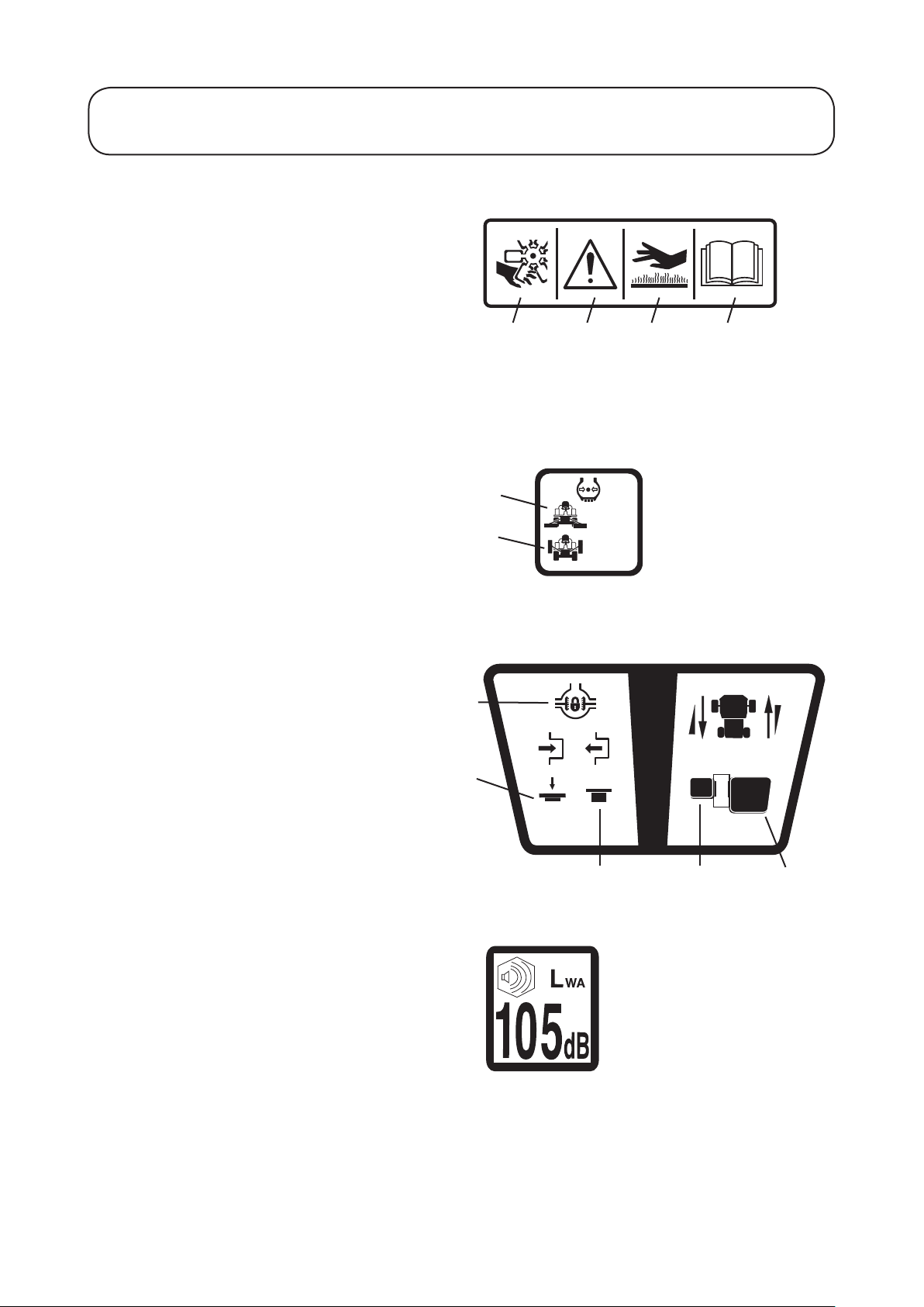
Decals
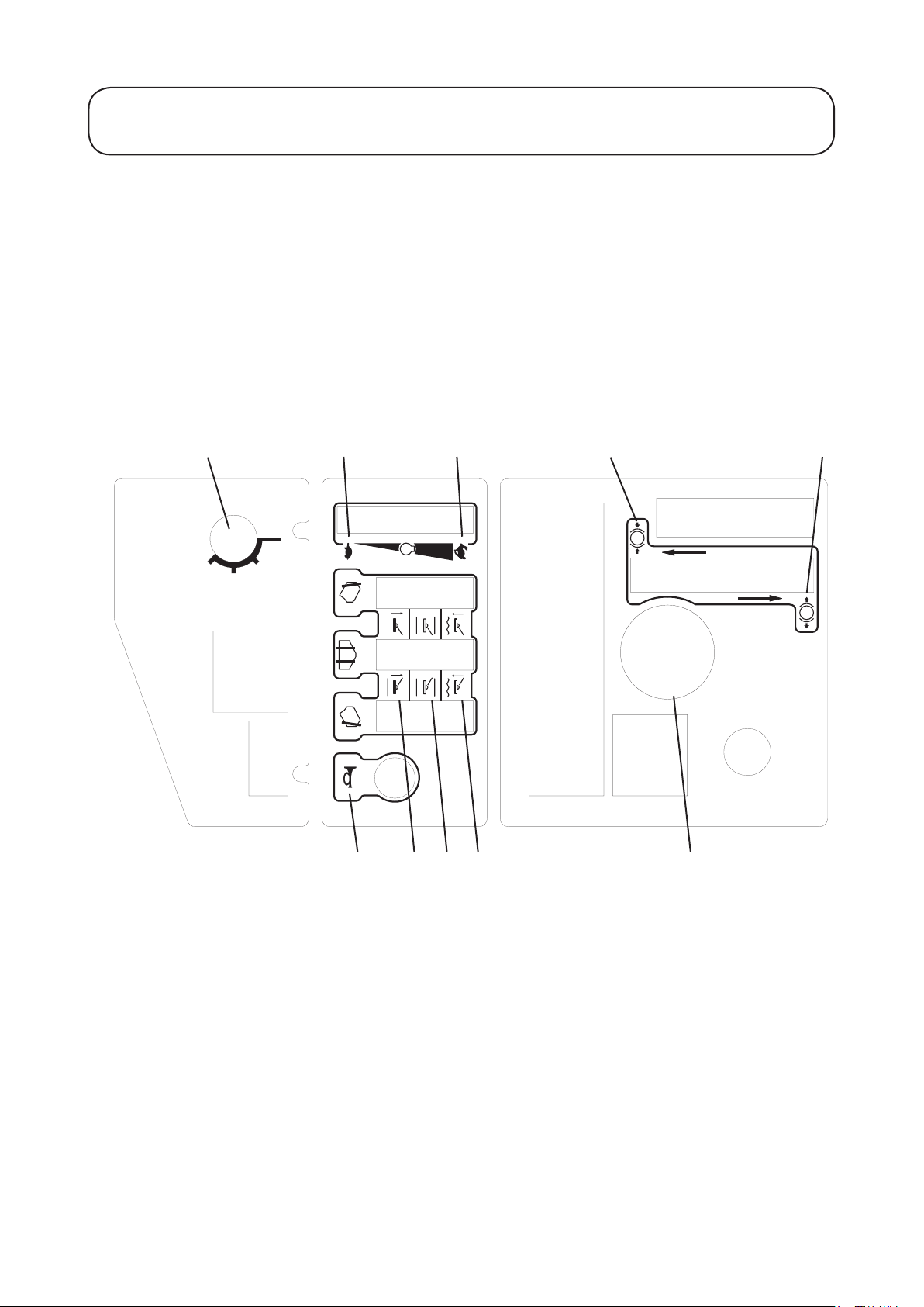
Decal - Control Panel
Part No: 994910 (A)
Location: Control Panel
A) Ignition Switch F) Horn
B) Engine Speed - Slow G) Cutters - Lift
C) Engine Speed - Fast H) Cutters - Hold
D) Parking Brake - Engage I) Cutters - Drop/Float
E) Parking Brake - Disengage J) Hour Meter
A B C D E
JIHGF
Page 14
14
111-0955 (A)
1.14 1.14
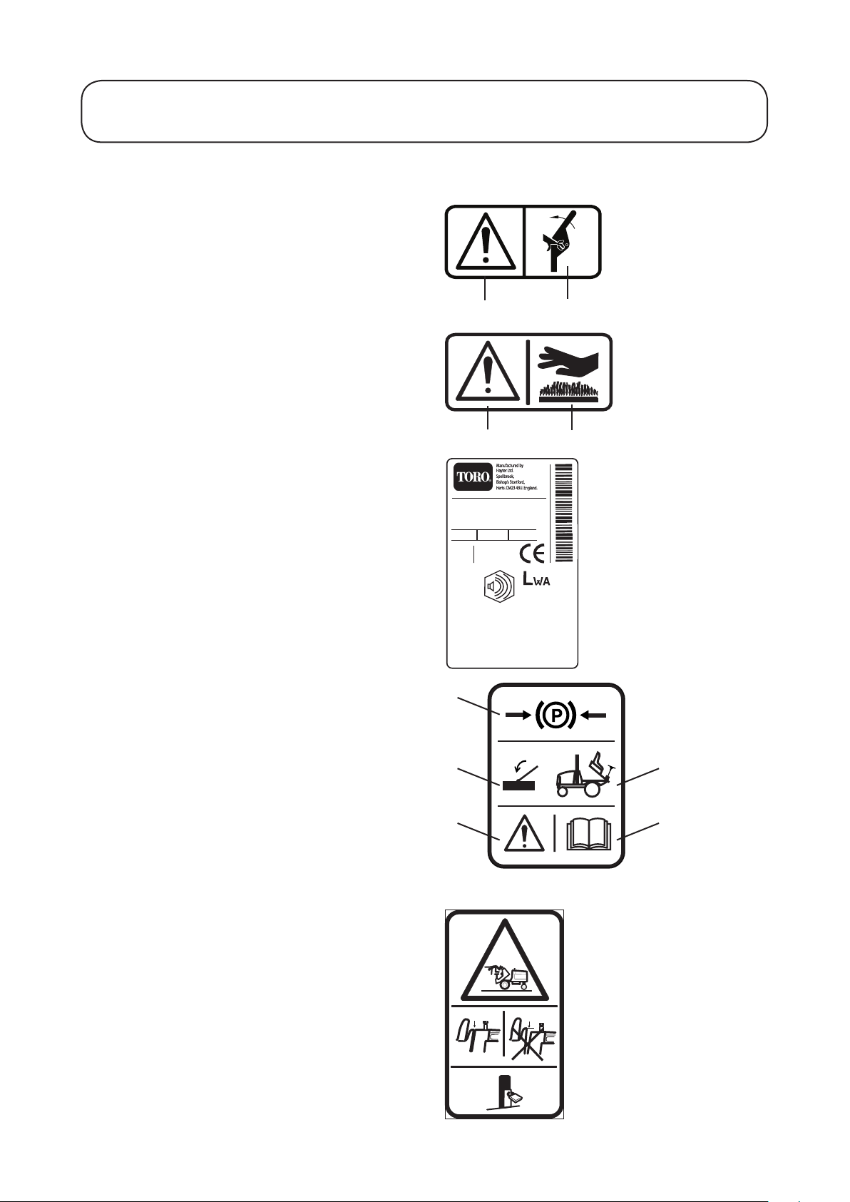
SAFETY PRECAUTIONS
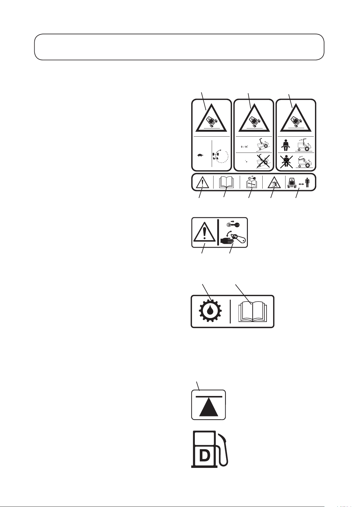
Decals continued
Decal - Inclines Part No: 111-0955 (A)
Location: Centre Platform
A) Warning - Travel slowly when turning and on
slopes
B) Warning - Maximum Slope
C) Warning - Seat belt must be worn only with a
R.O.P.S in the vertical position.
D) Caution
E) Read Operators Manual
F) Stop engine/Remove ignition key before servicing
or maintenance
G) Beware of ying objects
H) Keep bystanders clear
Decal - Danger Latch Part No: 70-13-077 (0)
Location: LH / RH / Centre Arms
A) Caution
B) Stop engine/Remove ignition key before releasing
or operating safety latches.
A
D E F
A
B
B C
G H
Decal - Transmission Oil
Part No: 111-3901 (A)
Location: Oil ller bracket mounted behind fuel tank.
A) Transmission Oil
B) Read and understand the Operators Manual.
Important: Fill the machine with the recom-
mended oil to the correct level. Failure to do so
will cause serious damage and invalidate the
warranty.
Decal - Jacking/Support Point
Part No: 70-13-072 (0)
Location: Front Axle - 2 points
Rear Towing eye
A) Jacking and Support Point
Decal - Diesel
Part No: 70-13-078 (0)
Location: Fuel Tank
Diesel fuel only
A B
A
Page 15
R
F
{
}
{
}
0.7 BAR
10 PSI
1.4 BAR
20 PSI
1.15 1.15
SAFETY PRECAUTIONS
Decals continued
Decal - Engine Fan/Radiator
Part No: 111-3902 (A)
Location: Engine Fan Cowl
A) Danger of severing ngers
B) Caution
C) Warning - Hot Surfaces
D) Read and understand the Operators Manual
Important: Only remove radiator cap when the engine
is cool.
Decal - Tyre Pressure
Part No: 950832 (2)
Location: LH/RH Chassis - 4 places
A B C D
A
A) Mowing
B) Road Travel
Decal - Diff Lock / Control Pedal
Part No: 953876 (0)
Location: Centre Platform
A) Differential lock
B) Depress to engage diff-lock
C) Release to dis-engage diff-lock
D) Reverse speed - directional control
E) Forward speed - directional control
Decal - Noise
Part No: 922854
Location: Base of seat on GRP
B
A
B
DC
E
Page 16
105
dB
Code Serial No:
R3240T - 4WD
WIDE AREA MOWER
kg:1800
RPM
:2650 kW:44
2010
02770
3100000001
1.16 1.16
SAFETY PRECAUTIONS
Decals continued
Decal - Warning Crush Hazard
Part No: 111-0773 (A)
Location: Side of the ROPS frame
A) Safety Alert - Be aware to the possibility of injury
B) Crushing ngers. Force applied from side
Decal - Warning Hot Surface
Part No: 950889 (1)
Location: Right hand side of the machine
a) Safety Alert - Be aware to the possibility of injury
b) Warning - Hot surface
Decal - Serial Number
Location: Rear Bulkhead
A
A
B
B
Decal - Prevent Platform Damage
Part No: 111-3909 (A)
Location: Platform, Seat well
a) Engage parking brake
b) Lower cutterdecks
c) Caution
d) Raise/lower platform
e) Read and understand the Operators Manual
Decal - Warning Platform Latch
Part No: 924868
Location: Next to Platform Latch
WARNING - PREVENT ACCIDENTS: Ensure
platform is correctly seated and the latch is fully
locked before operating the machine.
A
B
C
D
E
Page 17
A
B
1
2
3
4
5
1
3
5
7
9
2
4
6
8
1
3
5
7
9
2
4
6
8
1
2
3
4
5
6
7
8
9
1 A
2 A
3 A
4 A
5 A
2 B
3 B
4 B
5 B
25mm 1"
38mm 1.5"
51mm 2"
64mm 2.5"
76mm 3"
89mm 3.5"
102mm 4"
114mm 4.5"
127mm 5"
-
-
-
-
-
-
-
-
-
994907 (rev.0.)
1
2
3
4
5
6
7
8
9
1
2
3
4
5
1
1
2
2
3
3
4
4
5
1
2
3
4
5
6
7
8
9
T
B
T
B
T
B
T
B
T
25mm 1"
38mm 1.5"
51mm 2"
64mm 2.5"
76mm 3"
89mm 3.5"
102mm 4"
11 4mm 4.5"
127mm 5"
-
-
-
-
-
-
-
-
-
1.17 1.17
SAFETY PRECAUTIONS
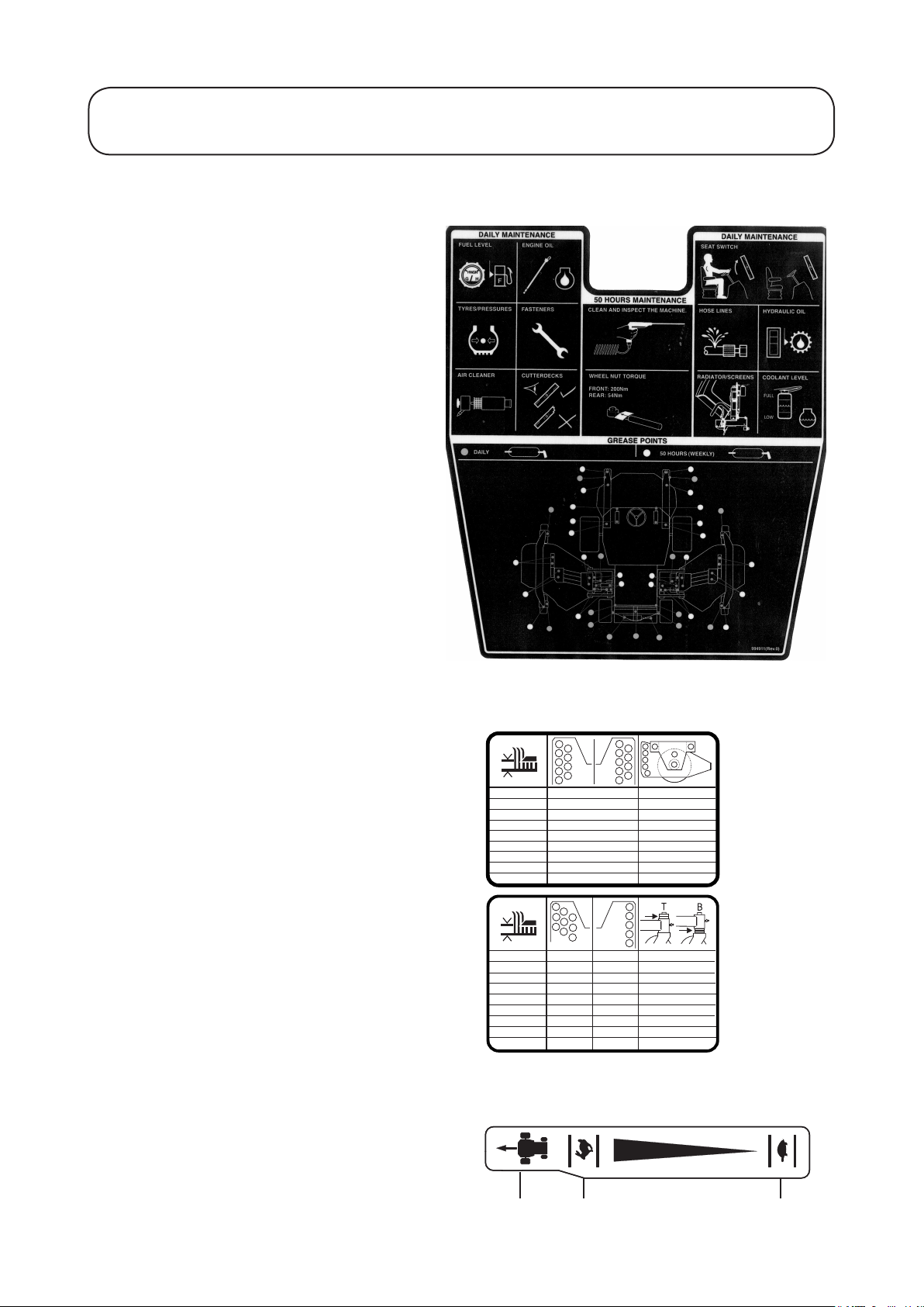
Decals continued
Decal - Maintenance R3240T
Part No: 994911 (2)
Location: Underside of engine cover next to latch.
Decal - Height of Cut
Part No: 994906 (0)
Part No: 994907 (0)
Location: On decks
Decal - Pedal Backstop
Part No: 953877 (1)
Location: Platform RH Side
A) Forward travel
B) Slow
C) Fast
A
B C
Page 18
B = 994806
994806 X2
A = 994805
994805 X2
A
LH
RH
A
B
1.18 1.18
SAFETY PRECAUTIONS
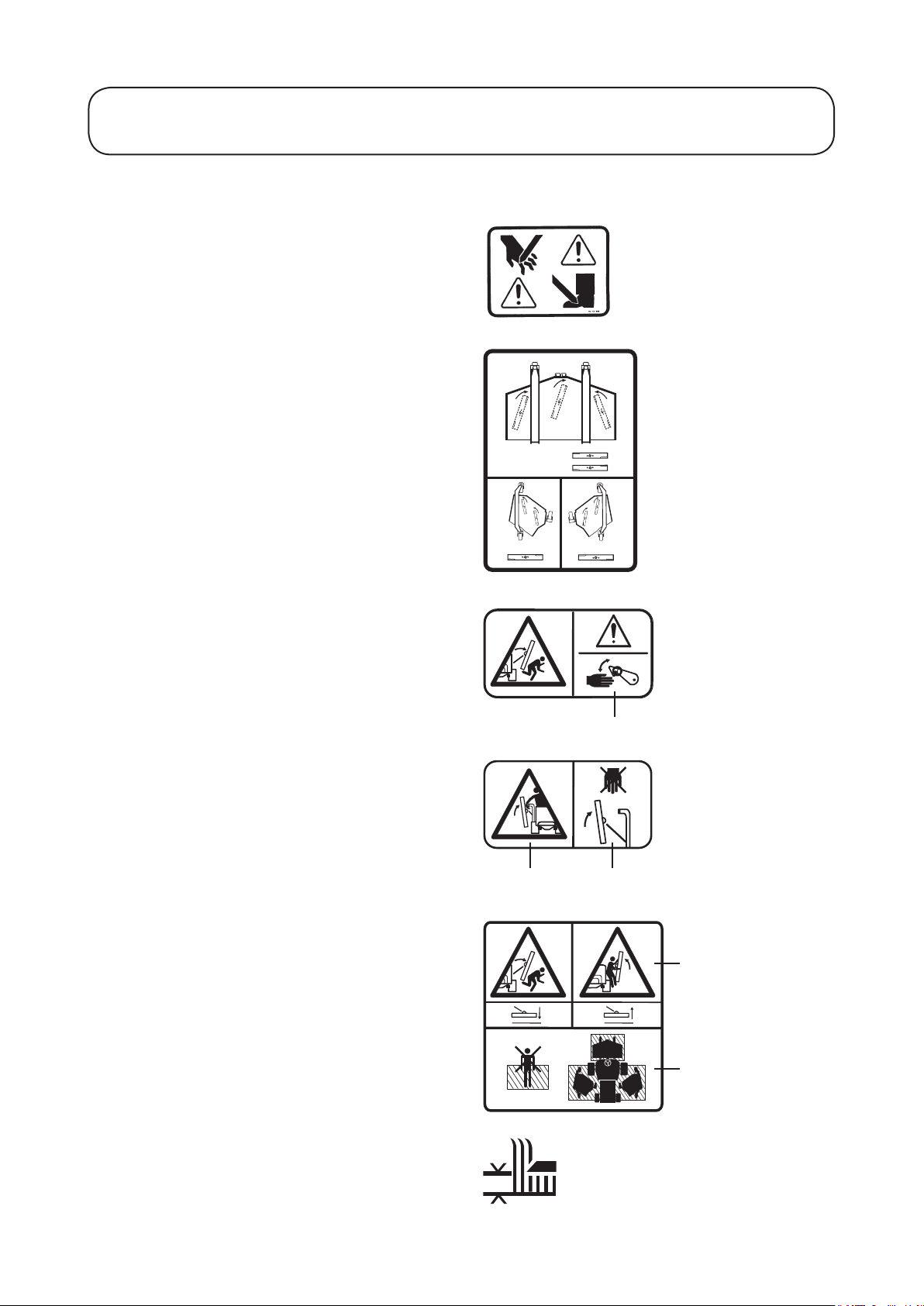
Decals continued
Decal - Warning Hands, Feet
Part No: 40-13-010 (1)
Location: On decks
Decal - Blade
Part No: 994913-1 (0)
Location: On decks
Decal - Spring Hazard
Part No: 994913_2 (0)
Location: Side of machine
A) Take care when latching and unlatching the
cutterdecks.
Decal - Crushing Hand
Part No: 994913_3 (0)
Location: Side of machine
A) Warning of crushing hazard when the wing decks
are bring raised.
B) Keep hands clear
Decal - Crushing Hazard
Part No: 994913_4 (0)
Location: Side of machine
A) Warning of crushing hazard when cutterdecks are
being raised or lowered
B) Keep clear of the shaded area when the cutterdecks
are being raised or lowered
A
A B
A
B
Decal - Height of Cut
Part No: 320006 (1)
Location: On decks
Page 19

105
dB
Code Serial No:
R3240T - 4WD
WIDE AREA MOWER
kg:1800
RPM
:2650 kW:44
2010
02770
3100000001
1.19 1.19
EC CONFORMITY INFORMATION
Noise Levels
Operator Daily Personal Noise Exposure:
TORO have no control over site conditions, duration of
use, state of maintenance or adjustment of the mower.
All of these factors will affect the operator’s daily
personal noise exposure level - L
Under typical working conditions operators could be
exposed to a daily personal noise exposure level in
excess of 85 dB (A) L
Sound pressure level:
The sound pressure level at the operator’s position is 85
dB (A) measured in accordance with European Standard
EN836.
Sound power level:
The guaranteed sound power level is 105 dB (A)
measured in accordance with EC Directive 2000/14/EC.
EP,d
EP,d
If hearing protection is required, ear protectors with good
attenuation in the 63 - 8000 Hz frequency range should
be used.
Employers of personnel using this machine should refer
to the 2003/10/EC Directive for minimum health and
safety requirements regarding exposure and risks to
physical agents (noise).
Vibration Levels
Operator Daily Personal Vibration Exposure:
TORO have no control over site conditions, duration of
use, state of maintenance or adjustment of the mower.
All of these factors will affect the operator’s daily
personal vibration exposure level.
Under certain working conditions the operator may be
exposed to vibration levels above those stated.
Wear Hearing
Protection
Page 20
Manufactured for: T oro Company
EC DECLARATION OF CONFORMITY
By: Hayter Limted
declare that thelawnmower
Model name:
Type:
Model No:
Cutting width:
Speed of rotation of the
cutting device:
Engine manufacturer:
Speed of rotation of engine:
Complies with the provisions of Directive: 2006/42/EC Essential Health & Safety Requirements relating to the Design &
Construction of Machinery and Safety Components and the regulations transposed into national law.
Also Directive 2004/108/EEC Electromagnetic Compatibility and the regulations transposed into national law.
Also Directive 79/622/EEC Roll-over protection structures of wheeled agricultural or forestry tractors (static testing), as
amended and the regulations transposed into national law.
Also Directive 2000/14/EC Noise emission in the environment by equipment for use outdoors, as amended and the regulations
transposed into national law.
Procedure applied for the conformity assessment: ANNEX VI, proced ure 1.
Notified Body: Sound Research Laboratories Ltd. Holbrook House, Little Waldingfield, Sudbury, Suffolk. CO10 0TH.
ENGLAND
Notified body identification No: 1088
Measured sound power level:
Guaranteed sound power level:
Authorised Signatory:
S.A Maryniak
(Technical Director)
Declaration done and technical documentation kept at:
HAYTER LIMITED
Spellbrook, Bishop s Stortford,
Herts. CM23 4BU ENGLAND
Date: 12.04.2010
VIBRATION INFORMATION
Address: Spellbrook, Bishop s Stortford, Herts. CM23 4BU. ENGLAND
Hand / Arm Vibration Level at the Operator Position measured in accordance with European Standard EN 836:
Measured Vibration Level ahv =
Uncertainty of measurement K =
Whole Body Vibration Level at the Operator Seat measured in accordance with European Standard EN 836:
Measured Vibration Level aw =
Uncertainty of measurement K =
SOUND PRESSURE INFORMATION
Sound Pressure Level at the Operator Position measured in accordance with European Standard EN 836:
Measured Sound Pressure Level LPA =
Uncertainty of measurement K =
ms
-2
dB(A)
ms
-2
ms
-2
ms
-2
dB(A)
R3240T
Ride-on Rotary
02770
350 cm
2350 rpm
Kubota
2650 rpm
0.5
1.0
1.0
0.5
02770
105 dB(A)
105 dB(A)
87
2
02770
02770
1.20 1.20
EC CONFORMITY INFORMATION
Page 21

1.21 1.21
INTRODUCTION
Introduction
The R3240T is a diesel engine powered self-propelled machine with hydraulic systems for ground drive, cutterdeck drives and steering.
The machine can be operated in either two wheel or four wheel drive and a differential lock function may be
selected in four wheel drive.
The Toro R3240T is a precision built machine designed solely for cutting grass and similar low lying ground
vegetation within the limitations stated in this manual. Do not use the R3240T in any other way other than its
intended use. Compliance with and strict adherence to the conditions of operation, service and repair as specied
in this Operators Manual also constitute essential elements of the intended use. The way in which this machine is
operated and maintained will have a profound effect on its performance and reliability.
This manual contains advice on the Toro R3240T which should be operated, serviced and repaired only by persons
who are familiar with its particular characteristics and who are acquainted with the relevant safety procedures.
The safety precautions listed here in and all other generally recognised regulations on safety and all road trafc
regulations must be observed at all times.
Any arbitrary modications carried out to this machine may relieve the Toro Company of liability for any resulting damage or injury.
In the pursuit of continuous product development The Toro Company reserves the right to alter specications
without notice.
Cutterdeck Variants: The R3240T can be tted with a range of cutterdeck congurations and optional extras:
Cutterdeck Cutterblade Length
Centre
LH
RH
Optional Extras:
Beacon Kit - Amber ashing warning light.
Lighting Kit - Complies with EC trafc regulations.
R.O.P.S. Cab - Full weather protection and roll - over protection.
Note: with a ROPS cab tted the stability angle will decrease, due to the higher centre of gravity of the
machine.
560mm (22˝)
560mm (22˝)
560mm (22˝)
Number of
cutterblades
3
2
2
Direction of rotation
Viewed on motor shaft end
RH Blade - Clockwise
Middle Blade - Anti-clockwise
LH Blade - Anti-clockwise
Clockwise
Anti-clockwise
When tting optional extra kits to the mower be sure to x the serial number decal supplied with the kit to the
chassis LH side. This will help the spare parts department to supply the correct spare parts throughout the service
life of the mower.
Left and right: Throughout this manual the terms ‘left’ and ‘right’ refer to the machine when looking in the
direction of forward travel.
Page 22

1.22 1.22
SPECIFICATIONS
Specications
ALL FIGURES ARE NOMINALLY QUOTED AT THE RATED ENGINE SPEED OF 2800 RPM
UNLESS OTHERWISE STATED.
Engine
R3240T
Type: Kubota V2403 Diesel
4 cylinders in line
Power Rating: 44 kw (59 hp) @ 2700 rpm
DIN 70020
Capacity: 2434 cc (148.5 cu in)
Air Cleaner: Clean air drawn through screened air intake
in rear of engine cover via a cyclonic air
cleaner with built in pre-cleaner.
Cooling System: Water cooled
Battery: 12V 480 Amps S. A. E.
Alternator: 40 Amps
Starter: 1.4 kw (1.6 hp) Electric
Cold Starting: Glow plug
Idle Speed: 1250 (± 50) rpm
Fuel Type: Diesel
Fuel Tank Capacity: 70 Litres (15.4 UK Gallons)
IMPORTANT - PREVENT DAMAGE: For further information regarding the engine, refer to the Engine
Manual.
Transmission System
Drive Type: Hydraulic
Pump: Variable displacement hydraulic piston pump with integral charge pump
and servo control
Wheel Motors: Front Axle - ‘twin lock’ radial piston, xed displacement, with integral disc
brake (pressure released)
Rear Axle - radial piston, xed displacement with pedal control (only
available in work mode)
Differential Lock: Electro - hydraulic control valve
Drive: Front wheel drive in ‘work’ and ‘transport’ modes.
Relief Valve Setting: Main service relief 350 bar (5075 psi) differential
Charge pressure relief 29 bar (421 psi) differential
Page 23

1.23 1.23
SPECIFICATIONS
Cutterdeck Drive System
Drive Type: Hydraulic
Pump: Tandem hydraulic gear type
Delivery Rate: 45.3 Litres per minute - All decks (10 UK gallons per minute)
Cutterdeck Motors: Hydraulic motors, pressure balanced with integral differential pressure
sensing relief check valve. Direct drive to cutterdecks
Control: Electro-hydraulic
Automatic diverter valve safety cut-off
Relief Valve Setting: 250 bar (3625 psi) differential
Cutterdeck Lift System and Steering
Drive Type: Hydraulic
Pump: Hydraulic gear pump with integral relief valve
Delivery Rate: 11 litres per minute (2.9 UK gallons per minute)
Steering: Power beyond hydrostatic steering valve with priority ow to steering and
auxiliary ow to cutterdeck lift system. Manual emergency steering.
Cutterdeck Lift Control: Mechanical hydraulic
Relief Valve Setting: 120 bar (1523 psi) on pump
Hydraulic System
Hydraulic Oil Type: Refer to RECOMMENDED LUBRICANTS AND HYDRAULIC FLUIDS
Capacity: 77 Litres (17 UK gallons)
Cooling: Combined aluminium oil and water cooler
Suction Line Filtration: 125 micron no bypass mesh lter
Return Line Filtration: 10 micron with 2 bar (29 psi) bypass check valve
Transmission Filtration: 10 micron no bypass pressure lter
Maximum Oil
Contamination Level: ISO Code 18/13 or better (ISO 4406)
1300 particles / ml < 15 μ
40 to 80 particles / ml > 15 μ
Maximum Oil Temperature: 95 C (203 F)
Page 24

1.24 1.24
SPECIFICATIONS
Vehicle Specications
0 - 24 km/hr (0 - 15 mph) Forward
Travel Speed:
0 - 11 km/hr (0 - 7 mph) Reverse
Tyres Tyre Type Recommended Tyre Pressures
Turf Conditions Road Conditions Max Pressure
Front Axle
Rear Axle
Wheel Nut Torque Settings: Front Axle 200Nm (148 lbf.ft)
Rear Axle 54Nm (40 lbf.ft)
Service Brakes: Closed loop hydrostatic service braking operating on drive wheels only
Parking Brake: Lever operated oil immersed disc brakes on front wheels only. Pressurised
hydraulic oil release with mechanical override for emergency towing purposes
Ground Clearance: 180mm (7.1˝) with cutterdecks raised
Steering: Hydrostatic rear wheel steering, emergency manual steering
Features: Tilting operator platform
Lockable engine cover
Adjustable suspension seat with folding arms
Adjustable steering column
Cutterdeck parking latches with safety locks
Back lapping facility
Differential lock
Engine coolant and hydraulic oil overheat audible warning (horn)
Hydraulic oil lter blocked telltales on control panel
Wing arm breakback
26 x 12 - 12 4 ply 0.7 bar
(10 psi)
20 x 10 - 8 4 ply 0.7 bar
(10 psi)
1.4 bar
(20 psi)
1.4 bar
(20 psi)
1.7 bar
(25 psi)
1.7 bar
(25 psi)
Safety Features: Neutral start interlock on transmission pump, parking brake and
cutterdeck drive switch.
Neutral start telltales on control panel
Operator presence control (seat switch)
Cutterdeck drive automatic cut-off on lift
2 Post folding ROPS designed and tested to European Directive 79/622/EEC.
Page 25

1.25 1.25
SPECIFICATIONS
Operator Controls
Steering: Automotive padded steering wheel with adjustable steering column
Cylinder Drive: Electric switch (on - off)
Engine Speed: Hand lever
Parking Brake: Hand lever
Forward and Reverse: Separate foot operated pedals
Ignition: Key start, shut - off and engine preheat
Differential Lock: Foot pedal
‘Work’ or ‘transport’ modes: Electric switch
Cutterdeck Position: Hand lever
Horn: Button switch
Weight Transfer: Hand wheel
Instrumentation
Warning Lights: Engine oil pressure
Battery charge
Engine coolant temperature
Hydraulic transmission oil temperature
Gauges: Digital hour meter
Fuel level
Hydraulic oil level sight glass
Indicator Lights: Engine pre-heat
Hydraulic return lter blocked
Hydraulic transmission lter blocked
Cutterdeck drive switch off
Parking brake engaged
Transmission neutral
‘Work’ mode active
Page 26

1.26 1.26
SPECIFICATIONS
Weight and Dimensions
Wheel Base: 1610 mm (63.4˝)
Working Width: 3610 mm (142.1˝) - At 100mm (4˝) height of cut
Cutting Width: 3500 mm (137.8˝) - At 100mm (4˝) height of cut
Transport Width: 1774 mm (69.8˝) - At 50mm (2˝) height of cut
Overall Length: 3470 mm (136.6˝)
Overall Height: 1750 mm (68.9˝) with R.O.P.S folded
2404 mm (94.6˝) with R.O.P.S in its vertical operating position
Working Weight: Including 2 post R.O.P.S, cutterdecks and full tank of fuel. It excludes the
operator and any other options.
1869 kg (4120 lb)
Recommended Lubricants and Hydraulic Fluids
Grease Points: A good quality medium grease
Engine: Refer to Engine Operators Manual
Hydraulic System:
Ambient Temperature Range
0 - 30 C (32 - 86 F) 15 - 40 C (59 - 104 F)
ISO viscosity grade
46 hydraulic oil
Should you be in any doubt please contact your TORO dealer. Using incorrect grades will cause premature wear
of hydraulic components and invalidate warranty.
ISO viscosity grade
68 hydraulic oil
Cutterdecks
Centre Cutterdeck Left/Right Cutterdeck
Cutterdeck Width: 1675 mm (65.9˝) 1150 mm (45.3˝)
Cutting Width: 1600 mm (63˝) 1090 mm (42.9˝)
Cutterblade Length: 558 mm (22˝) 558 mm (22˝)
Cutterblade Speed: 2400 rpm approx 2400 rpm approx
Cutterblade Overlap: 63 mm (2.5˝) 40 mm (1.6˝)
Height of Cut: 26 mm (1˝) to 127 mm (5˝) 26 mm (1˝) to 127 mm (5˝)
Number of Blades: 3 2
Conguration: Semi-oating Fully oating
Breakback Mechanism: - Gas spring
Tyres: Puncture preventative Puncture preventative
Page 27

1.27 1.27
OPERATING THE MOWER
Safety Notice
WARNING: PREVENT ACCIDENTS - Before operating the mower it is essential that;
- The operator reads and understands this manual.
- The operator platform latching mechanism is fully engaged and in good working order, refer to
OPERATOR PLATFORM LATCHING MECHANISM.
- The daily maintenance checks have been properly carried out and the mower is in good working
order.
- The operator should wear safety clothing and eye protection. Failure to do so could result in risk to
health and safety.
- The area where the equipment is to be used is inspected and all objects which may be thrown by the
machine are removed.
Operate safely on slopes;
It is essential to follow safe working practices when working on slopes. In order to avoid potentially
hazardous situations, it is essential that the operator understands and observes the relevant safety
precautions listed in this manual, refer to SAFETY PRECAUTIONS.
This machine is tted with a R.O.P.S as standard to increase operator safety in the event of the
machine rolling over.
The R.O.P.S frame may be folded down to allow access into area of restricted height.
While the R.O.P.S is folded down it does not provide any protection in the event of a roll over and
should not be considered as a Roll Over Protective structure.
Operator Presence Control
Cutterblade Drive Lockout: Drive to the cutterblades is only possible when the operator is seated. If the
operator raises off the seat for a period of more than one second, a switch is activated and drive to the cutterblades is automatically disengaged. To re-engage drive to the cutterblades, the operator must return to the
seat, then operate the cutterdeck drive switch to the ‘OFF’ position before moving it back to the ‘ON’ position. If the operator rises off the seat for a brief moment during normal work, drive to the cutterblades is not
affected.
Note: The engine can only be started with the cutterdeck drive switch in the ‘OFF’ position.
Engine Start Lockout: The engine can only be started when the forward/reverse travel pedal is in the
‘NEUTRAL’ position, the cutterdeck drive switch is in the ‘OFF’ position and the parking brake is engaged.
When these circumstances are satised, switches are activated permitting the engine to be started.
Engine Run Interlock: Once the engine is started the operator must be seated before the parking brake is
released for the engine to continue to run.
Note: The engine will cut out if the operator leaves the seat without engaging the parking brake.
WARNING: PREVENT ACCIDENTS - Do not operate the turf mower if the operator presence
controls are defective in any way. ALWAYS replace faulty parts and check that they function
correctly before operating the mower.
Page 28

1
2
5
6
10
9
4
7
8
11
14
13
12
15
16
18
19
20
21
17
3
23
24
29
28
26
31
30
25
27
22
1.28 1.28
OPERATING THE MOWER
Identication of Control Panel Components
1. Parking brake lever
2. Lighting switch
(supplied with lighting kit)
3. Warning beacon switch
(supplied with beacon kit)
4. Hazard warning switch
(supplied with lighting kit)
5. Cutterdeck position controls
6. Throttle control lever
7. Ignition key
8. Cutterdeck drive switch
9. Dip beam / main beam light switch
(supplied with lighting kit)
10. Direction indicator switch
(supplied with lighting kit)
11. Horn button
12. Transmission oil lter indicator
13. Oil pressure indicator
14. Transmission temperature indicator
15. Return oil lter indicator
16. Battery warning indicator
17. Engine temperature warning indicator
18. Glow plug indicator
19. Cutterdeck drive off indicator
20. Parking brake indicator
21. Transmission neutral indicator
22. Forward travel speed backstop lever
23. ‘Work’ / ‘transport’ mode switch
24. Hour meter
25. Forward travel speed backstop cam
26. Front cutterdeck transport latch
27. Reverse travel pedal
28. LH wing unit transport latch
29. RH wing unit transport latch
30. Differential lock pedal
31. Forward travel pedal
32. Wash / wipe switch
(supplied with cab kit)
Page 29

P
1.29 1.29
OPERATING THE MOWER
Braking System
Parking brake engaged
Parking brake: Move the parking brake lever to its rear position to engage the
parking brake. Do not operate the mower with the parking brake engaged.
WARNING: PREVENT ACCIDENTS The parking brake operates on the front wheels only. Do not park the mower on a slope.
Service brakes: Service braking is achieved by the hydraulic transmission system. When the forward or
reverse travel pedals are released or the engine speed reduced, service braking becomes effective and travel
speed is automatically reduced. To increase the braking effect, push the transmission pedal into the neutral
position.
WARNING: PREVENT ACCIDENTS The service braking system will not hold the mower at a standstill. ALWAYS ensure the parking brake
is engaged to park the mower at a standstill.
Emergency braking: In the event of service brake failure, turn the ignition off to bring the mower to a
standstill. This will automatically apply the parking brake.
WARNING: PREVENT ACCIDENTS Take care when using the emergency braking. Remain seated and hold on to the steering wheel to prevent ejection from the mower caused by the front wheel brakes being applied suddenly when travelling.
Throttle Control
Operate the throttle control in a forward direction to
increase the engine speed.
Operate the throttle control in a rearward direction
to reduce engine speed.
Note that the engine speed dictates the speed of the
other functions, i.e. travel, cutting cylinder, position
controls.
Travel
Forward travel: Depress the forward travel pedal
to increase forward travel speed.
Release the pedal to reduce speed.
Reverse travel: Depress the reverse travel pedal to
increase reverse travel speed.
Release the pedal to reduce speed.
Stop (Neutral): Release the forward or reverse
travel pedal.
Engine speed
Fast Slow
Page 30

1.30 1.30
OPERATING THE MOWER
Work / Transport Modes
WARNING: PREVENT ACCIDENTS Ensure that the mode selected is appropriate to
the mode of operation of the machine.
Select ‘work’ mode when operating the mower in
conditions of poor traction when maximum tractive
performance is required. Selecting ‘work’ mode
will enable the use of the differential lock.
Select ‘transport’ mode when operating the mower
in conditions of good traction. For example when
travelling on the public highway or mowing large,
level, open areas. Selecting ‘transport’ mode in
these conditions will reduce transmission system
wear and tear.
1
Differential lock is not available for use when
‘transport’ mode is selected.
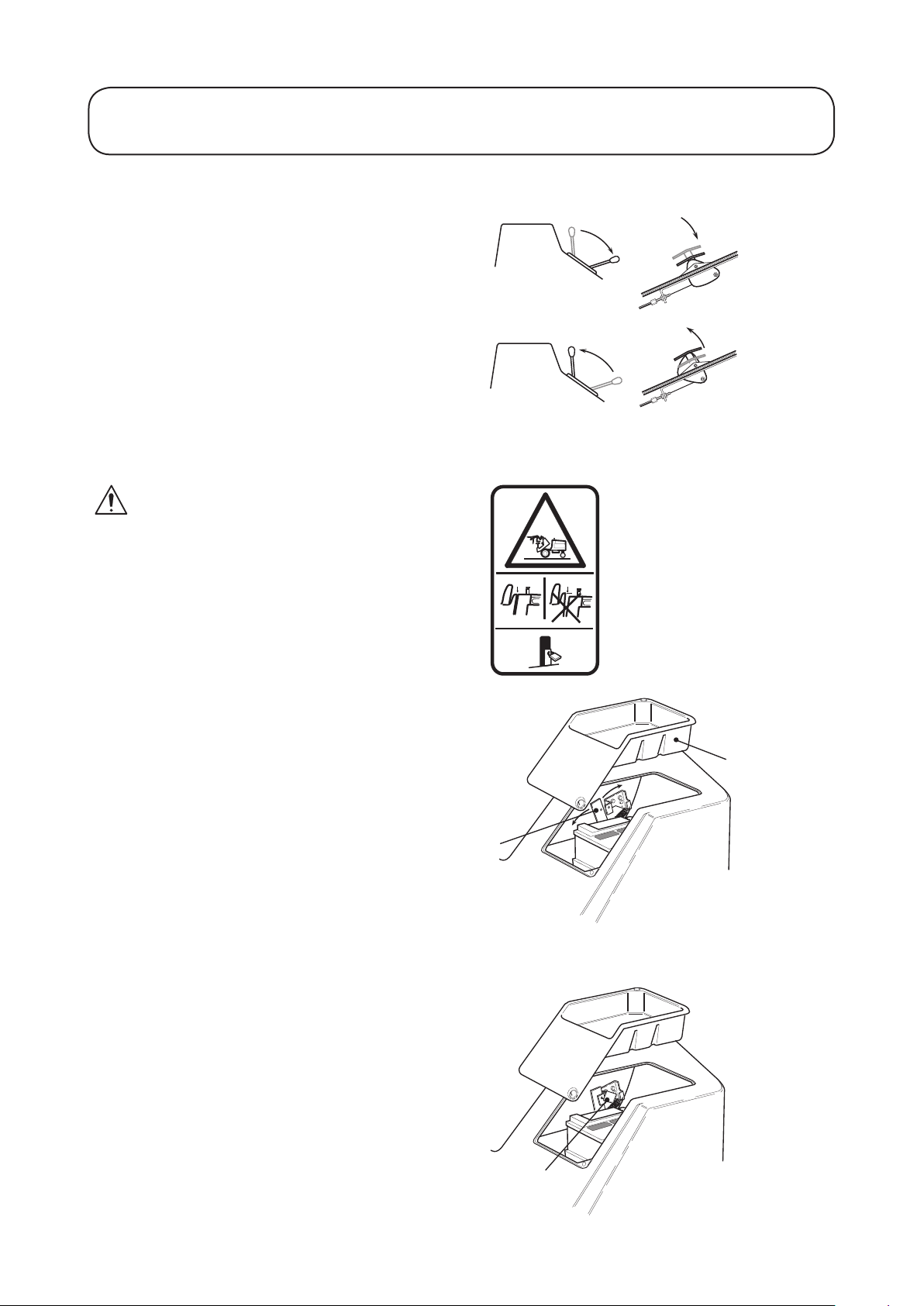
Transport Latches
WARNING: PREVENT ACCIDENTS ALWAYS raise the cutterdecks to the transport
position and secure with the transport latches
and safety locks when travelling between work
areas.
Wing cutterdeck transport latches:
Front cutterdeck transport latch:
1. Transport mode
2. Work mode
2
1
1
2
WARNING: PREVENT ACCIDENTS Stored energy devices are charged when the
outer wing units are in the transport position.
Always operate the relevant lift controls to
provide hydraulic support for the cutterdeck
suspensions before attempting to release the
transport latches.
2
1. Transport latch
2. Safety lock
Page 31

1.31 1.31
OPERATING THE MOWER
Differential Lock
WARNING: PREVENT ACCIDENTS Do not engage the differential lock at high
speed. The turning circle will increase with the
differential lock engaged.
The differential lock is effective only when ‘work’
mode is selected.
The differential lock operates in both ‘forwards’
and ‘reverse’ and can be engaged whilst the mower
is travelling slowly. Engage the differential lock to
prevent excessive power requirements by operating
with differential lock at slow speed.
1
Engaging differential lock:
Depress the differential lock pedal.
Disengaging differential lock:
Release the differential lock.
Travel Control Pedals
WARNING: PREVENT ACCIDENTS Ensure that the transmission control cable is
securely fastened to the travel control pedal
mechanism. Ensure that both the cable and
pedals articulate freely through their full range
of travel and that the mechanism freely returns
to neutral when released.
WARNING: PREVENT ACCIDENTS Ensure that the control cable is correctly routed
underneath the operator platform such that it is
clear of any obstructions and impediments to its
operation.
This is of particular importance after the
platform has been opened and subsequently
closed following inspection maintenance
operations.
Before operating the machine, ensure that there
are no foreign objects or liquids on the platform
or pedals - ALWAYS KEEP THE OPERATOR
PLATFORM CLEAR/CLEAN.
Page 32
2
1
A
B
3
1.32 1.32
OPERATING THE MOWER
Forward Travel Speed Backstop Lever
The backstop lever can be used to limit the
movement of the forward pedal for accurate
forward travel speed, and the clip rate required.
Operate the lever in a forward direction to increase
the travel speed setting and in a rearward direction
to decrease.
Note: This is not a cruise control device. Releasing
the forward travel pedal will allow it to return to
neutral.
Operator Platform Latching Mechanism
WARNING: PREVENT ACCIDENTS -
Never operate the mower without rst checking
that the operator platform latching mechanism
is fully engaged and in good working order.
Check behind the seat and ensure that the top
of the platform is ush with the top of the fuel
tank. Also check beneath the tool tray and
ensure that the release lever is padlocked in the
correct position.
IMPORTANT: PREVENT DAMAGE Engage the parking brake and lower the
cutterdecks to the ground. Remove ignition key
and close ignition key and close ignition cover
before raising and lowering the platform.
Releasing the platform: Release and remove the
tool tray from the left hand side of the platform.
Release the padlock securing the locking latch
handle with key provided. Move the locking latch
handle towards the front of the mower (position A)
until the latch hooks clear the locking bar and raise
the platform. The gas spring will provide
assistance.
Securing the platform: Lower the platform
carefully. The gas spring will provide assistance.
Move the locking latch handle towards the front
of the mower (position A) as the platform nears
the fully lowered position. This will ensure that the
latch hooks clear the locking bar. Fully lower the
platform and move the locking handle towards the
rear of the mower (position B) until the latch hooks
fully engage the locking bar. Replace the padlock
in order to secure the locking latch handle in place.
1. Tool tray
2. Locking latch handle
3. Padlock
A. Release
B. Lock
Page 33

A
A
1.33 1.33
OPERATING THE MOWER
Adjustable Steering Column
WARNING: PREVENT ACCIDENTS Before operating the mower, ensure that the steering column adjuster mechanism is in good working
order and that the steering wheel is locked securely in position.
WARNING: PREVENT ACCIDENTS Adjustment of the steering wheel and steering column should only be carried out when the mower is at
a standstill with the parking brake engaged.
Adjusting the angle of inclination of the steering
wheel: Move lever ‘A’ downwards to adjust the
angle of steering wheel. Release the lever to lock the
steering wheel in position.
Adjusting the length of the steering column: Move
the lever ‘A’ upwards to adjust the length of the
steering column. Release the lever to lock the steering
column in position.
Page 34
1
2
3
4
3
4
1.34 1.34
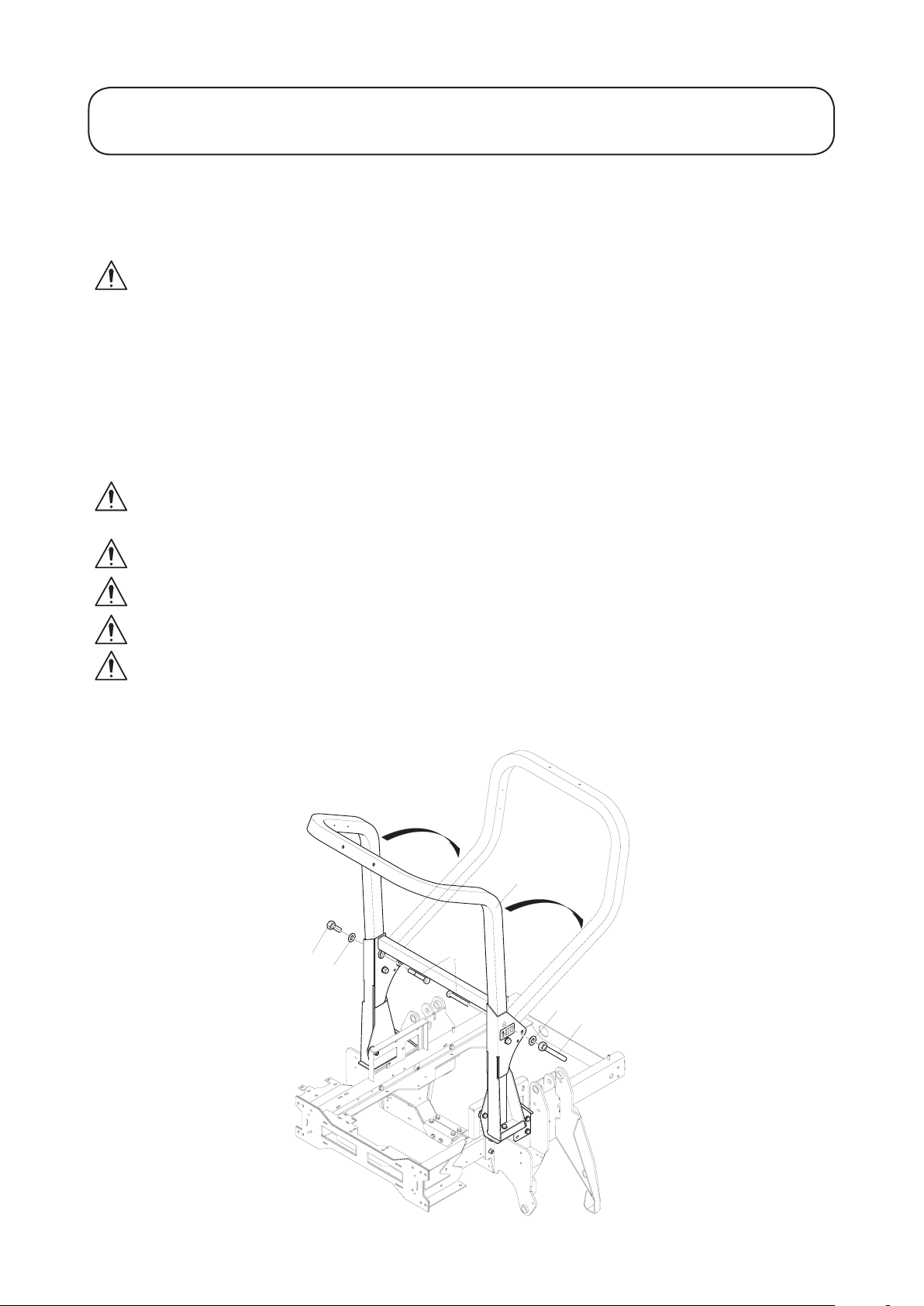
OPERATING THE MOWER
Folding the R.O.P.S
The R.O.P.S frame may be folded down to allow access into areas of restricted height.
WARNING: PREVENT ACCIDENTS - While the R.O.P.S frame is folded down it does not
provide any protection in the event of a roll-over and should not be considered as a Roll Over
Protective Structure.
1. Lower the cutterdecks, apply the parking brake and switch off the engine.
2. Support the weight of the upper frame (item 1) while removing the hand nuts, washers and retaining
bolts (items 2, 3 & 4) from the pivot brackets. Refer to Fig 2.
3. Carefully lower the frame downwards until it rests on the stops.
4. Insert the retaining bolts in the lower hole and fully tighten the hand nuts to support the upperframe in its
lowered position.
5. To raise the frame, follow these instructions in reverse order.
WARNING: PREVENT ACCIDENTS - When in the raised position, both retaining bolt
assemblies (items 2, 3 & 4) must be installed and fully tightened to ensure full R.O.P.S protection.
WARNING: PREVENT ACCIDENTS - Be careful lowering and raising the R.O.P.S frame to
prevent entrapment of ngers between xed part and pivot part of the structure.
Keep all nuts, bolts and screws correctly torqued ensure that the equipment is in safe working condition.
Replace worn or damaged parts for safety.
Ensure that the seat belt and mountings are in safe working order.
Fig 2
Page 35

B
C
D
CW
CCW
E
1.35 1.35
OPERATING THE MOWER
Operator Seat
WARNING: PREVENT ACCIDENTS - Before operating the mower ensure that the operator seat
mechanisms are in good working order and that the seat is locked securely in position.
WARNING: PREVENT ACCIDENTS - Adjustment of the seat mechanisms should only be carried out
when the mower is at a standstill with the parking brake engaged.
Fore/Aft Adjustment: Move lever ‘B’ upwards to
adjust the Fore/Aft position of the seat. Release the
lever to lock the seat in position.
Operator weight adjustment: Rotate handle ‘C’
clockwise as shown to increase suspension stiffness
and counter-clockwise to decrease. Dial ‘D’ indicates
when the optimum suspension has been set according
to operator weight (kg).
Height adjustment: Manually lift the seat for
incremental height adjustment. To lower lift the seat
to beyond its highest setting, then allow it to drop to
the lowest setting.
Backrest adjustment: Pull handle ‘E’ outwards to
adjust the seat backrest angle. Release the handle to
lock the seat backrest in position.
Page 36

1.36 1.36
OPERATING THE MOWER
Warning Systems
Engine coolant overheating warning:
The engine coolant warning light illuminates, the
horn is actuated and the cutters stop.
Hydraulic oil overheating warning:
The hydraulic oil warning light illuminates and
the horn is actuated when the hydraulic oil in the
reservoir exceeds 95˚ C (203˚ F) approx.
Low battery charge warning:
The battery charge warning light illuminates.
Low engine oil pressure warning light:
The engine oil pressure warning light illuminates.
Audible Warning Horn
Depress the horn button to provide an audible
warning.
IMPORTANT: PREVENT DAMAGE - The
horn is automatically actuated when an engine
coolant or hydraulic oil overheat condition
occurs. STOP the engine immediately and effect
remedial action before restarting.
Page 37

I
II
III
O
FUEL
E
F
D
3 4 5 5 9
1.37 1.37
OPERATING THE MOWER
Ignition Key
0 = Engine off.
I = Engine run / Auxiliary on.
II = Engine pre-heat.
III = Engine start.
WARNING : PREVENT ACCIDENTS - Always remove the ignition key when the mower is not in use.
IMPORTANT: PREVENT DAMAGE - Always t the protective cap when the ignition key is removed
to prevent ingress of dirt and moisture from damaging the mechanism.
Engine Pre-Heat Indicator Light
Turn the ignition key to position II. The engine
pre-heat indicator light will illuminate. When the
correct pre-heat temperature is achieved, the indicator
light will switch off. When this condition is achieved,
turn the ignition key to position III to start the engine.
IMPORTANT: PREVENT DAMAGE - Attempting to start a cold engine before the pre-heat is used
can cause unnecessary wear to the battery.
Fuel Level Gauge
Displays fuel tank level.
Hour Meter
Displays engine running hours.
Page 38

N
P
1.38 1.38
OPERATING THE MOWER
Transmission Neutral Indicator Light
Illuminates when the travel control pedal is in the
neutral position and the ignition key is turned to
position ‘I’.
Note: The parking brake must be engaged for the
transmission neutral indicator light to illuminate.
Cutterdeck Drive Switch Indicator Light
Illuminates when the cutterdeck drive switch is in
the ‘off’ position and the ignition key is turned to
position ‘I’.
Parking Brake Indicator Light
Illuminates when the parking brake is engaged and
the ignition key is turned to position ‘I’.
Hydraulic Return Filter Indicator Light
Illuminates when the return lter element is blocked.
Note: The engine must be running for the hydrau-
lic return lter indicator light to illuminate. The
indicator light may illuminate briey when the
hydraulic oil is cold.
Hydraulic Transmission Filter Indicator
Light
Illuminates when the transmission lter element is
blocked.
Note: The engine must be running for the hydrau-
lic return lter indicator light to illuminate. The
indicator light may illuminate briey when the
hydraulic oil is cold.
Transmission System ‘Work’ Mode Indicator Light
Illuminates when the transmission system ‘work’
mode is selected and the ignition key turned to
position ‘I’.
Page 39

1
2
1.39 1.39
OPERATING THE MOWER
Cutterdeck Position Control
The cutterdecks may be raised or lowered
independently using the bank of 3 lift control
levers.
To lower the cutterdecks, operate the lift control
levers in a downward direction until locked into
position. If the cutterdeck drive switch is in the
‘on’ position, the cylinder drive will engage when
the cutterdecks are approximately 300mm (11.8)
above ground level.
IMPORTANT: PREVENT DAMAGE - The
lift control levers must be locked in position 1
while moving. NEVER mow with the lift control
levers in position 2 (neutral).
To raise the cutterdecks, operate the lift control
levers in an upward direction and hold in
position 3. If the cutterdeck drive switch is in the
‘on’ position, the cylinder drive will disengage
when the cutterdecks are approximately 300mm
(11.8) above ground level. Release the lift control
levers when the cutterdecks are at the required
height. The control levers will automatically return
to position 2 (neutral).
1
2
3
4 5 6
1. Down/oat
2. Neutral
3. Raise
4. LH wing
5. Centre
6. RH wing
Cutterdeck Drive Engagement
The cutterdeck drive can be engaged only when the
operator is seated correctly, refer to OPERATOR
PRESENCE CONTROLS.
Briey operate the lift control levers to raise the
cutterdecks, thereby removing the cutterdeck
suspension deadweights and wing units stored
energy reaction from the transport latch mechanisms.
Release the cutterdeck latches. Operate the cutterdeck position controls to the down / oat position
and lower all cutterdecks to the ground ready for
mowing.
Forward rotation cutterdeck drive engagement:
Operate the cutterdeck drive switch to the ‘On’
position.
To disengage all cutterdeck drives: Operate the
cutterdeck drive switch to the ‘Off’ position.
WARNING: PREVENT ACCIDENTS - Refer
to OPERATOR PRESENCE CONTROLS for
additional information.
1. On
2. O
Page 40

I
II
III
O
1
1.40 1.40
OPERATING THE MOWER
Starting The Engine
WARNING: PREVENT ACCIDENTS - Before
starting the engine check that;
- You have read and understood the Safety
Precautions section in this manual.
- The area is clear of bystanders.
- The cutterdeck drive is disengaged.
- The parking brake is engaged.
- The travel control pedals are in neutral.
This machine is tted with an Engine Start
Lockout, refer to OPERATOR PRESENCE
CONTROLS.
Starting a cold engine: Set the throttle control
lever to approximately 70% full throttle.
Turn the ignition key to the ‘ignition on’ position
‘I’ and check that the engine oil pressure and battery charge warning lights illuminate.
Turn the ignition key to the ‘preheat’ position ‘II’
and hold until the engine pre-heat indicator light
goes out.
Turn the ignition key to the ‘start’ position ‘III’
and hold to crank the engine. As soon as the engine
starts release the ignition key back to position ‘I’.
WARNING: PREVENT DAMAGE - When the
engine is operating all warning lights should
be ‘off’. If a warning light illuminates, stop the
engine immediately and have the fault rectied
before restarting.
Starting a warm engine: Engine pre-heating is
unnecessary when restarting an engine which has
been stopped for a few minutes. Follow the cold
engine starting procedure without holding in
‘preheat’ position ‘II’.
1. Engine pre-heat indicator light
Page 41

I
II
III
O
1.41 1.41
OPERATING THE MOWER
Stopping The Engine
Allow the engine to idle for 5 minutes before shutting it off after a full load operation. Failure to do
so may lead to turbo charger trouble.
General Operating Hints
1. The rotational speed of the cutterblades should
always be kept as high as possible in order to
maintain the highest quality of cut. This in turn
requires that the engine speed be kept as high
as possible.
2. The quality of cut will deteriorate if the
forward speed is excessive. Always balance the
quality of cut with the work rate required and
set the forward speed accordingly.
3. Never let the engine labour. Reduce the
forward speed or increase the height of cut.
Check that the cutterblades are in good
condition.
4. Always disengage the cutterdeck drive when
travelling across ungrassed areas.
5. Take care not to leave uncut strips of grass at
the overlap points between adjacent cutterdecks
by avoiding tight turns.
WARNING: PREVENT ACCIDENTS - Take
care when travelling over obstacles such as
roadside kerbs. ALWAYS travel at slow speed
over obstacles to prevent damage to the machines tyres, wheels and steering system. Ensure
that tyres are inated to the recommended pressures.
Page 42

994907 (rev.0.)
1
2
3
4
5
6
7
8
9
1
2
3
4
5
1
1
2
2
3
3
4
4
5
1
2
3
4
5
6
7
8
9
T
B
T
B
T
B
T
B
T
25mm 1"
38mm 1.5"
51mm 2"
64mm 2.5"
76mm 3"
89mm 3.5"
102mm 4"
114mm 4.5"
127mm 5"
-
-
-
-
-
-
-
-
-
1.42 1.42
OPERATING THE MOWER
Cutterdeck General Information
Height of Cut Adjustment - Front Cutterdeck
To adjust the height of cut on the front cutterdeck follow the procedure below. Ensure that the mower is stationary on a level surface with the parking brake engaged and the cutterdeck drive disengaged.
WARNING: PREVENT ACCIDENTS - Never adjust the height of cut with the engine running.
Read all of these instructions before commencing.
1. Raise the deck to transport position and engage transport latches.
2. Switch off the engine and remove the ignition key.
3. Remove the front castor assemblies from the support beams.
4. Disengage the front deck transport latches and lower the cutterdeck on to suitable supports so that it is
safely supported approximately 130mm from the ground. Leave the lift lever in the oat position.
5. Remove the HOC positioning bolts. Lift or lower the castor wheel support beam and replace the bolts in
the appropriate holes to achieve the desired HOC. For bolt positions refer to the HOC decal on the deck
or to the picture in this manual. Note the required position of the spacers on the front castors.
6. Tighten these bolts but do not overtighten.
7. Start the engine, raise the cutterdeck to the transport position and engage the transport latches.
8. Switch off the engine.
9. Replace the front castor, placing the spacers in the required positions.
Decal - Front cutterdeck Height of Cut settings
Hole / Spacer Positions.
Page 43

A
B
1
2
3
4
5
1
3
5
7
9
2
4
6
8
1
3
5
7
9
2
4
6
8
1
2
3
4
5
6
7
8
9
1 A
2 A
3 A
4 A
5 A
2 B
3 B
4 B
5 B
25mm 1"
38mm 1.5"
51mm 2"
64mm 2.5"
76mm 3"
89mm 3.5"
102mm 4"
114mm 4.5"
127mm 5"
-
-
-
-
-
-
-
-
-
1.43 1.43
OPERATING THE MOWER
Cutterdeck General Information Cont’d
Height of Cut Adjustment - LH & RH Cutterdecks
To adjust the height of cut on the LH and RH cutterdecks follow the procedure below. Ensure that the mower
is stationary on a level surface with the parking brake engaged and the cutterdeck drive disengaged.
WARNING: PREVENT ACCIDENTS - Never adjust the height of cut with the engine running.
Read all of these instructions before commencing.
1. Disengage the LH deck transport latch and lower the cutterdeck onto suitable supports so that it is safely
supported approximately 130mm from the ground.
2. Remove the HOC positioning bolts on the castor beam. Lift or lower the castor wheel support beam and
replace the bolts in the appropriate holes to achieve the desired HOC. For bolt positions refer to the HOC
decal on the deck or to the picture in this manual.
3. Tighten these bolts but do not overtighten.
4. Start the engine. Raise the cutterdeck and engage the transport latch. Switch off the engine and remove
the ignition key.
5. Remove the inner wheel assembly xing bolts and reposition to achieve the desired HOC. For some HOC
settings, the castor wheel must be repositioned in its carrier. For bolt positions refer to the HOC decal on
the deck or the picture in tis manual.
6. Tighten these bolts.
7. Repeat this procedure for the RH cutterdeck.
8. The attitude of the wing decks can be adjusted. To raise the rear of the deck, the spacers above the rear
chassis pivot bush can be repositioned under the pivot bush. This will raise the rear of the deck.
Decal - LH / RH cutterdeck Height of Cut settings
Hole / Spacer Positions.
Page 44

1.44 1.44
MAINTENANCE
Maintenance
WARNING: PREVENT ACCIDENTS - When carrying out maintenance procedures it is essential that:
- The engine is switched off and the ignition key removed.
- The parking brake is applied.
- There is no pressure in the hydraulic system.
- The cutterdecks are fully down on the ground.
- The safety precautions in this manual have been read and understood.
WARNING: PREVENT ACCIDENTS - Stored energy devices and systems are used on the R3240T
mower. It is essential that this stored energy is safely dissipated before maintenance or other service or
operations are performed on these devices and systems on the machine.
Dissipate stored energy as described below:
Hydraulics:
Transmission System: Ensure that the machine is on level ground, engage the parking brake and switch the
engine off. Depress for forward and reverse travel pedals alternatively several times.
Cutterdeck Lift System: Lower the cutterdecks to the ground and switch the engine off. Raise and lower the
lift levers several times leaving them in the ‘down/oat’ position.
Cutterdeck Drive System: Lower the cutterdecks to the ground with the cutterdeck drive switch in the ‘off’
position and switch the engine off.
Wing Cutterdeck Gas Springs: Lower the wing cutterdecks to the ground ensuring that the movement of the
cutterdeck is not impeded in anyway.
Operator Platform Gas Spring: Raise the platform fully.
Steering: Ensure that the machine is on level ground, engage the parking brake and switch off the engine.
IMPORTANT: PREVENT DAMAGE - Regular maintenance is essential for the continued safe
operation of the machine. Correct servicing will prolong the working life of the machine and safe-
guard the ‘Warranty’. Always t genuine ‘TORO service parts’ as these are accurately matched to the
required duty.
Dirt and contamination are the enemies of any hydraulic system. When carrying out maintenance procedures
on the hydraulic system always ensure that the work area and the components are thoroughly clean before,
during and after retting. Ensure that all open hydraulic lines and ports, etc. are plugged during maintenance
procedures.
The recommended service intervals are based on normal operating conditions. Severe or unusual conditions
will necessitate shorter service intervals.
ALWAYS grease pivot points immediately after pressure washing or steam cleaning, refer to EVERY 50
HOURS, GREASE PIVOT POINTS.
WARNING: PREVENT ACCIDENTS - The engine, transmission oil and hydraulic systems will be hot
after machine use. Allow the systems to cool before working on the machine, particularly before work-
ing on the engine or when changing oil or oil lters.
Page 45

1.45 1.45
MAINTENANCE
Maintenance continued
WARNING: PREVENT ACCIDENTS - Use hazardous substances carefully.
The following uids are identied as being hazardous;
Substances Assessed risk
Diesel oil Low
Lubricating oil Low
Hydraulic oil Low
Grease Low
Anti - freeze Medium
Battery acid High
When using any of the above uids it is recommended that eye protection and gloves are worn and that
care is taken to prevent spillage.
Avoid contact with skin; wash off spillage with soap and water.
In the case of battery acid drench with water and seek medical attention. Remove any contaminated
clothing and clean thoroughly before use.
Avoid contact with eyes; wash with running water and seek medical attention if symptoms persist. In
the case of battery acid, seek medical attention immediately.
Avoid ingestion; if swallowed seek medical attention.
Keep clear of high pressure uid escaping from pinholes, cracked connections etc. High pressure uid
can penetrate the skin. Seek immediate medical advice if any uid is injected into the skin. Always use
a piece of cardboard or paper when searching for leaks.
CAUTION: PREVENT ENVIRONMENTAL DAMAGE - Dispose of hazardous substances
correctly.
When disposing of hazardous waste products, take them to an authorised disposal site.
Waste products must not be allowed to contaminate surface water, drains or sewerage systems.
CAUTION: PREVENT ENVIRONMENTAL DAMAGE - Dispose
of a used battery correctly. The battery has a separate collection mark.
This means that the battery must not be disposed of with general waste.
It must be taken to an authorised disposal site
Page 46

ENGINE
1
2
1
2
1.46 1.46
MAINTENANCE
Engine
Refer to the ENGINE OPERATOR’S MANUAL
for maintenance information.
Running In Period
Check wheel nut torque settings:
During rst 50 hours of use and in addition to
routine checks. Refer to DAILY AND BEFORE
USE. Check wheel nut torques twice a day.
Front axle wheel nut torque setting - 200 Nm (148
lbf.ft).
Rear axle wheel nut torque setting - 54 Nm (40 lbf.
ft).
Running In Period - At First 50 Hours
Change the transmission oil lter: Unscrew and
remove the bottom of the transmission oil lter
housing. Withdraw the lter element and discard.
Ret a new lter element (Part no. 924708) and
replace the housing.
Change the hydraulic oil return lter:
Unscrew and remove the return lter canister
and discard. Ret a new lter canister (Part no.
924692).
1. Transmission oil lter
2. Hydraulic oil tank
1. Hydraulic oil return lter
2. Engine fuel lter
Page 47

Low
Full
1
2
3
1.47 1.47
MAINTENANCE
Daily And Before Use
Check engine oil level: If the oil level is below the
upper mark on the dipstick, top up with the correct
grade of engine oil to the required level, refer to
ENGINE MANUAL.
Check engine radiator coolant level:
WARNING: PREVENT ACCIDENTS Avoid scalding. DO NOT remove the radiator
ller cap unless the engine is cool. Turn the ller
cap slowly to release system pressure before
removing the ller cap completely.
Keep coolant between ‘full’ and ‘low’ when engine
is cold at all times.
IMPORTANT: If you see RED in the Filter Blockage Indicator the air lter needs replacing.
Cleaning the air cleaner: Remove the air lter
and tap it repeatedly with the palm of the hand to
remove dust particles. DO NOT damage the air
lter by hitting it against a hard object. Inspect the
air lter for signs of damage.
IMPORTANT: PREVENT DAMAGE -
Always replace a damaged air lter or damage
to the engine will result. NEVER run the engine
without the air lter correctly tted.
Clean the inside of the cleaner dust bowl with a dry
cloth and check that the dust boot is not obstructed.
Replace the air lter and assemble the dust bowl,
with the dust boot facing below horizontal level.
1. Air lter
2. Dust bowl
3. Dust boot
Page 48

D
1
2
1.48 1.48
MAINTENANCE
Daily And Before Use continued
Clean the radiator screen: Clean the radiator
screen. Check the oil cooler and engine radiator
grille for debris and clean as necessary using a
brush or airline. If water is used, these areas should
be allowed to dry out completely before use.
IMPORTANT: PREVENT DAMAGE NEVER operate the mower with a damaged
radiator screen or engine damage could result
from overheating. Clean the radiator screen
more regularly in dry conditions.
Check fuel level: Top up as necessary with diesel
fuel. Always top up before storing the mower over-
night to prevent water condensation from contami-
nating the fuel.
1. Radiator screen
2. Radiator
Check hydraulic oil level: If the oil level is below
the upper mark on the sight level gauge, top up
with the correct grade of hydraulic oil as necessary,
refer to SPECIFICATIONS.
WARNING: PREVENT DAMAGE - If there
is noticeable hydraulic oil loss, the leakage
source must be rectied before using the mower.
NEVER operate the mower when the hydraulic
oil level is below the bottom mark on the sight
level gauge. NEVER operate the mower with
contaminated oil.
Check hydraulic hose-lines: Inspect hydraulic
hose-lines for signs of wear or damage.
WARNING: PREVENT ACCIDENTS ALWAYS replace worn or damaged hydraulic
hose-lines immediately. DO NOT operate the
mower with defective hydraulic hose-lines.
Inspect the mower for signs of oil leakage. Tighten
ttings or replace seals as required.
Page 49

1.49 1.49
MAINTENANCE
Daily And Before Use continued
Check fasteners: Check that all nuts, bolts and
pins are secured correctly in place and in good
condition.
Check safety devices:
WARNING - PREVENT ACCIDENTS: Ensure
that all safety guards, shields and protective
devices are securely in place and in good working order.
Check tyres: Examine the condition of the tyres
and check that ination pressures are correctly set,
refer to SPECIFICATIONS.
WARNING - PREVENT ACCIDENTS: Ensure
that damaged tyres are replaced. Ensure that
tyre tread depths comply with road trafc
regulations.
Check cutterdecks: Examine the condition of the
cutterblades. Adjust as necessary, refer to MAINTENANCE.
WARNING - PREVENT ACCIDENTS: Do not
operate the machine if there are any signs of
‘Stickiness’ in the pedal mechanism which prevents a free return to the neutral condition.
Check operator presence controls:
WARNING: PREVENT ACCIDENTS - Keep
bystanders away when checking operator
presence control interlock switches. DO NOT
use the mower unless the operator presence
controls work correctly as described below. If
difculties arise, consult your authorised dealer.
Operator presence seat switch: Sit on the opera-
tor seat and start the engine. Lower the cutterdecks
to the ground and engage the cutterdeck drive.
Rise from the operators seat and check that the
cutterblades come to a stop after an initial 0.5 to 1
second delay.
Cutterdeck drive interlock switch: Stop the
mower engine. Operate the cutterdeck drive switch
to the ‘off’ position and turn the ignition key to
position ‘I’. The cutterdeck drive switch indicator
light should illuminate. Refer to OPERATING
THE MOWER.
Page 50

1.50 1.50
MAINTENANCE
Daily And Before Use continued
Operate the switch to the ‘on’ position. The indicator light should go out and the engine should not start
when the ignition key is turned.
Parking brake interlock switch: Stop the engine. Engage the parking brake and turn the ignition key to
position ‘I’. The parking brake indicator light should illuminate. Refer to OPERATING THE MOWER.
Disengage the parking brake. The indicator light should go out and the engine should not start when the
ignition key is turned.
Transmission neutral interlock switch: Stop the mower engine and engage the parking brake. Ensure that
the drive pedal is in the stop (neutral) position and turn the ignition key to position ‘I’. The transmission neutral indicator light should illuminate. Refer to OPERATING THE MOWER.
Depress the drive pedal. The indicator light should go out and the engine should not start when the ignition
key is turned. Carry out a similar check with the reverse travel pedal.
Note: The transmission neutral and parking brake indicator lights are connected in such a way that the transmission neutral light will illuminate only when the drive pedal is in the stop (neutral) position and the parking
brake is engaged.
Should any indicator light fail to illuminate when expected, check for blown bulbs or fuses.
Page 51
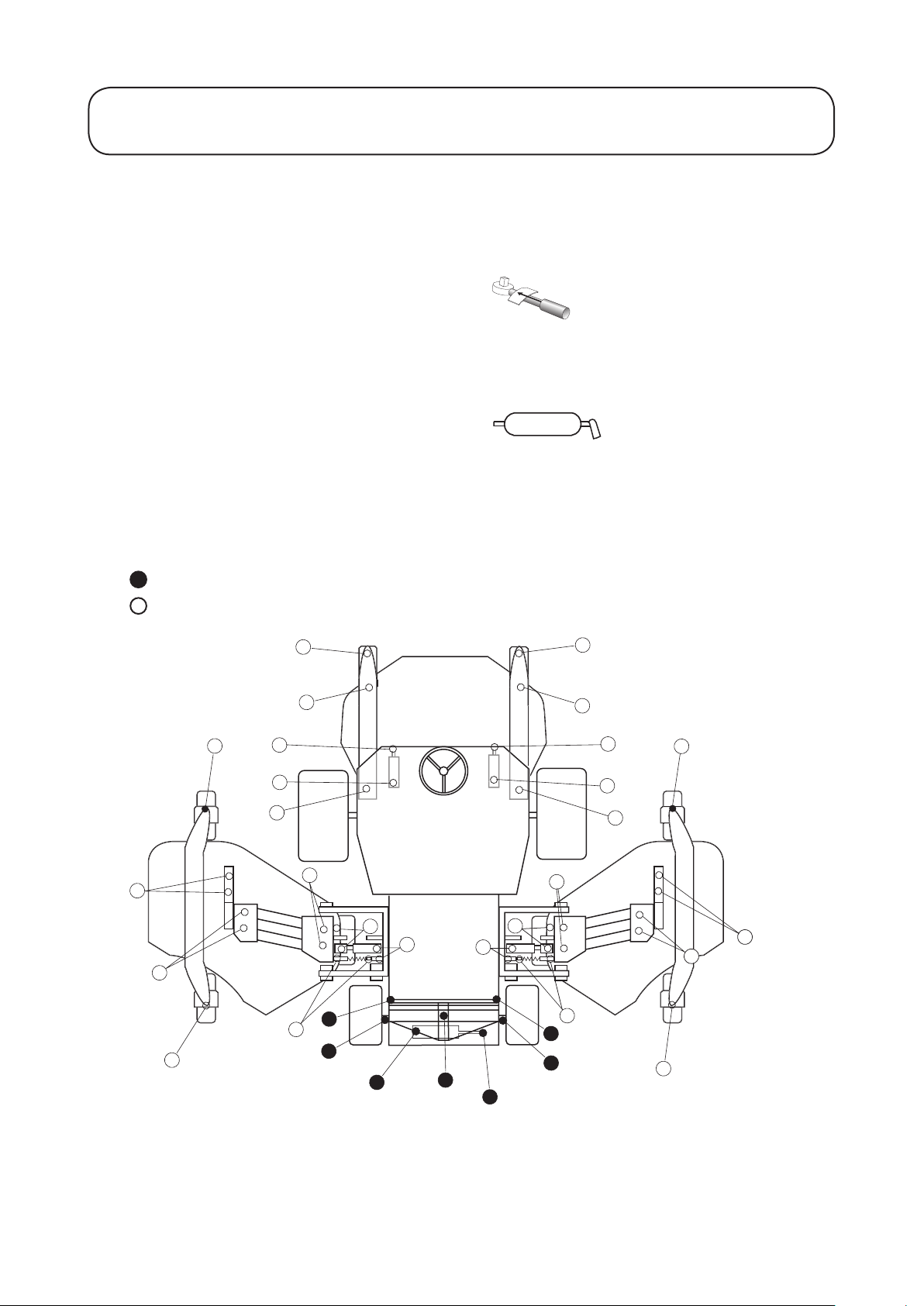
1.51 1.51
MAINTENANCE
Every 50 Hours
Perform routine checks: Refer to DAILY BEFORE USE.
Check wheel nut torque settings:
Front axle wheel nut torque setting - 200Nm (148
lbf.ft).
Rear axle wheel nut torque setting - 54 Nm (40 lbf.
ft).
Grease pivot points :
Clean and grease all grease points with a good
quality compound of the grade specied, refer to
SPECIFICATIONS.
Replace any grease nipples which are damaged.
Daily
Grease every 50 hours (weekly)
Page 52

Outer Cover Sleeve Rod EndRubber Seal Rubber Seal
1
2
1.52 1.52
MAINTENANCE
Every 250 Hours
Perform routine checks: Refer to - DAILY BEFORE USE.
- EVERY 50 HOURS.
Check battery condition:
WARNING: PREVENT ACCIDENTS - Explosive gases are produced by the battery. Work in a well
ventilated area, away from all sources of ignition.
Battery uids are corrosive. Take care to avoid contact with the skin or eyes. In the event of a
spillage, drench the affected area with water. If the eyes are affected, seek medical attention.
Remove any contaminated clothing and clean thoroughly before use.
When removing the battery, always disconnect the negative (-) cable rst.
When replacing the battery, always connect the negative (-) cable last.
Remove the tool tray to gain access to the battery. Remove any corrosion from the battery terminals using a
wire brush and apply petroleum jelly to the terminals to prevent further corrosion. Clean the battery compart-
ment.
Under normal operating conditions the battery will not require any further attention. If the machine has been
subject to continuous use under high ambient temperature conditions, the battery electrolyte may require topping up. Remove the cell covers and top up with distilled water to a height 15mm below the top of the battery.
Replace the cell covers.
IMPORTANT: PREVENT DAMAGE - Check
the condition of the battery cables. Replace cables
1. Battery
2. Tool tray
showing signs of wear or damage and tighten any
loose connections as necessary.
Visually inspect transmission control cable and
operating mechanism:
Check the condition and security of the cable and operating mechanism at the speed control pedals and transmission pump ends.
- Remove build up of dirt, grit and other deposits.
- Ensure that the ball joints are securely anchored and check that mounting brackets and cable anchors are
tight and free from cracks.
- Inspect end ttings for wear, corrosion, broken springs and replace if necessary.
- Ensure that the rubber seals are correctly located and in good condition.
- Ensure that the articulating sleeves supporting the inner cable are in good condition and rmly
attached to the outer cable assembly at the crimped connections. If there are any signs of cracking or
detachment t new cable immediately.
- Check that sleeves, rods and inner cable are free from bends, kinks and other damage. If there are
any signs of such failure, t a new cable immediately.
- Check the condition of the neutralising device and replace if worn.
- With the engine switched ‘Off’, operate the pedal controls through the entire range and ensure that
the mechanism moves smoothly and freely to the neutral position without ‘Sticking’ or ‘Hanging up’.
Page 53
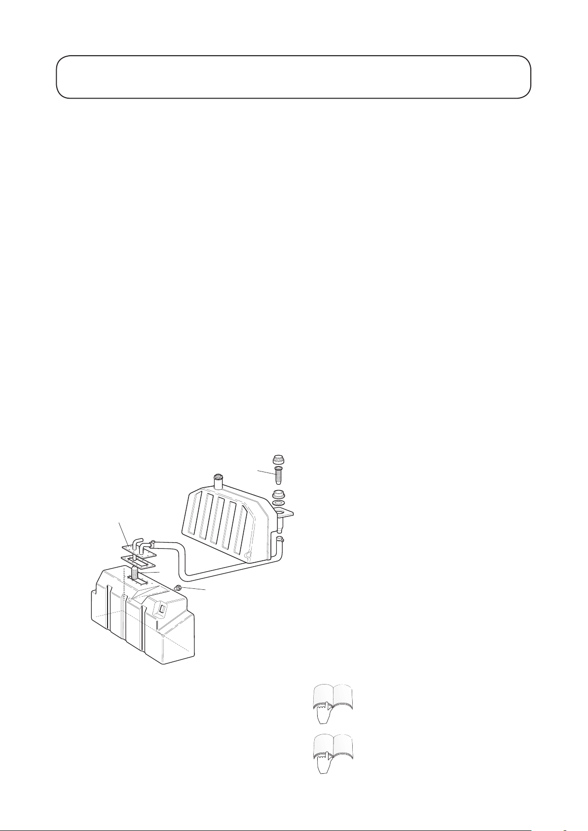
3
4
1
2
ENGINE
ENGINE
1.53 1.53
MAINTENANCE
Every 500 Hours
Perform routine checks: Refer to - DAILY BEFORE USE
- EVERY 50 HOURS
- EVERY 250 HOURS.
Thoroughly clean the machine:
IMPORTANT: PREVENT DAMAGE - Keep water away from electrical components. Use a dry cloth
or brush to clean such areas.
Service the hydraulic system: This procedure is best carried out when the hydraulic oil is warm (not hot).
Lower the cutterdecks to the ground and drain the hydraulic system by removing the hydraulic tank drain
plug. Remove the oil tank ller ange to gain access to the suction strainer. Unscrew and remove the strainer
and clean with parafn or petrol before replacing. Renew the strainer if there are any signs of damage.
Remove the oil ller cap strainer and clean before replacing. Renew the strainer if there are any signs of
damage.
Renew the return line oil lter element, refer to RUNNING IN PERIOD AT FIRST 50 HOURS.
Renew the transmission oil lter element, refer to RUNNING IN PERIOD AT FIRST 50 HOURS.
Replace the drain plug and rell the hydraulic tank with fresh clean hydraulic oil of the recommended grade,
refer to SPECIFICATIONS.
Run the machine and operate all hydraulic systems until the hydraulic oil is warm. Recheck the oil level and
top up as necessary to the upper mark on the sight level gauge.
1. Drain plug
2. Oil tank ller ange
3. Suction strainer
4. Filler strainer
Renew the engine air cleaner lter: Check the
condition of the air cleaner hoses. Replace any hose
which is damaged and tighten the connections, refer
to ENGINE MANUAL.
Renew the engine fuel lter element: Refer to
ENGINE MANUAL.
Page 54
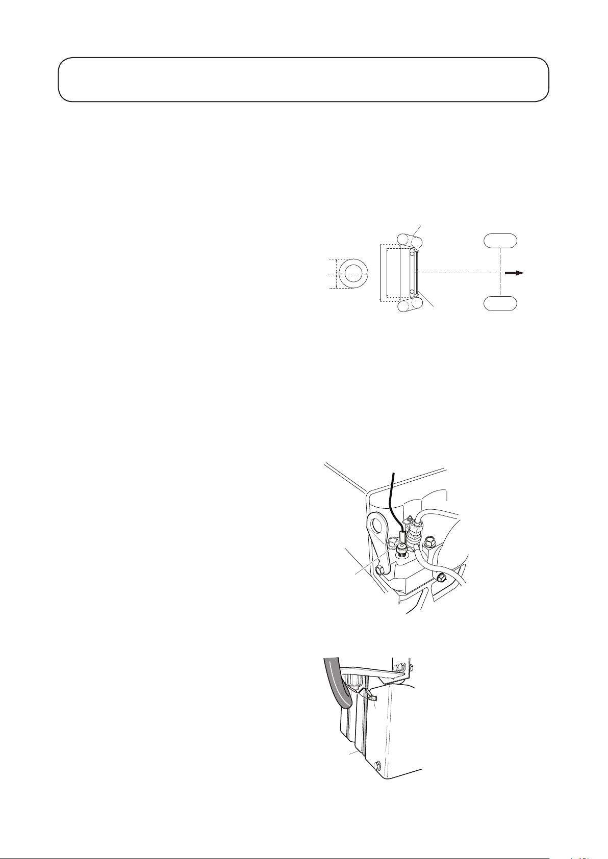
x + 3 - 8mm
x
4
3
2
1
1
1
2
1.54 1.54
MAINTENANCE
Every 500 Hours continued
Check electrical system:
Inspect all electrical connections and cables and
replace any which are damaged or corroded. Spray
a good quality water inhibitor onto exposed connections to prevent moisture ingress.
Check rear wheel alignment:
To prevent excessive tyre wear and ensure safe
machine operation, the rear wheels must be
correctly aligned to ‘toe - in’ by 3 mm (.12˝) - 8
mm (.31˝).
Set the rear wheels in the straight ahead position.
Measure and compare the distance between the
front sidewalls and the rear sidewalls at the wheel
centre height. The distance between the front
sidewalls must be set 3 - 8 mm less than the
distance between the rear sidewalls.
1. Wheel centre height
2. Tyre
3. Direction of forward travel
4. Track-rod assembly
To adjust the alignment of the rear wheels, rst
back off the left hand and right hand locknuts on
the track rod assembly. (Left hand locknut is a left
hand thread). Rotate the track rod to achieve the
correct ‘toe - in’ as described above and tighten the
locknuts securely.
Check the engine overheat warning system:
Turn the ignition key to the ‘ignition on’ position
‘I’. Disconnect the red/grey wire terminal from the
engine temperature switch and touch the metal
terminal of this wire onto a suitable earth point,
ensuring that the metal surfaces make good
contact. The horn will sound and the engine
coolant temperature warning light will illuminate
to conrm correct operation. If the system is faulty,
make repairs before operating the mower.
1. Temperature switch
Check the hydraulic oil overheat warning
system:
Turn the ignition key to the ‘ignition on’ position
‘I’. Disconnect the red/blue wire terminal from
the hydraulic tank temperature switch and touch
the metal terminal of the wire onto a suitable earth
point, ensuring that the metal surfaces make good
contact. The horn will sound and the hydraulic oil
temperature warning light will illuminate to
conrm correct operation. If the system is faulty,
make repairs before operating the mower.
1. Temperature switch
2. Hydraulic oil tank
Page 55

1.55 1.55
MAINTENANCE
Cutterdecks
Check tyres: Examine all tyres and replace any
that are damaged.
Check safety devices:
WARNING: PREVENT ACCIDENTS - Ensure
that all safety guards, shields and protective devices are securely in place and in good working
order. Check that cutterdeck drive cut outs
operate correctly and that the cutterblades do
not continue to operate when the cutterdecks
are more than 300mm above ground level.
Check fasteners: Check all nuts, bolts, pins and
locking devices. Ensure that they are secured correctly and replace any that are damaged.
Check underdeck areas:
WARNING: PREVENT ACCIDENTS - Switch
off the engine, apply the parking brake and
remove the ignition key before examining or
working on the underdeck areas.
Gain access to the wing underdeck areas by lifting
the cutterdecks to the transport position. Ensure
that the transport latches and safety locks are secured before working on the cutterdecks.
Gain access to the front underdeck area by using
the following procedure:
1. Fully raise the cutterdeck
2. Switch off the engine, apply the parking brake
and remove the ignition key.
3. Ensure that the transport latch and safety lock
is secured before working on the cutterdeck.
WARNING: PREVENT ACCIDENTS - Seek
assistance when carrying out the following
procedures.
Page 56

1.56 1.56
MAINTENANCE
Cutterblades
Cutterblade Removal
WARNING: PREVENT ACCIDENTS ALWAYS switch off the engine, apply the parking
brake and remove the ignition key before working on
the cutterblades. The cutterblades have sharp edges.
Wear strong gloves to protect the hands when working on the cutterblades.
DO NOT operate tools towards the cutting edges to
avoid the risk of injury should the tool slip. Always
use genuine Hayter replacement parts.
The condition of the cutterblades and their mountings
should be checked regularly for signs of wear or damage. Ensure that the cutterblades are not bent or cracked.
IMPORTANT: PREVENT DAMAGE Damaged or excessively worn cutterblades will cause
the cutting mechanisms to be out of balance. This
will cause excessive vibration and may lead to breakage. DO NOT use unbalanced cutterblades.
To remove and replace the cutterblades on Wing
Decks & Front Deck.
1. Raise front deck and wing decks to the transport
position and engage the latches and safety locks.
2. Switch off the engine, apply the parking brake
and remove the ignition key.
3. Remove the cutterblade assembly by rst bending
the cutterbar lock tabs (6) and unscrewing bolts
(item 1) and withdrawing from the deck/motor.
Note: The motor keys (items 5) are loose within the
mounting (items 4).
4. Remove the bolts (items 2) and lift away the
cutterblade mounting (items 4) and locating ring
(items 3) from the cutterblade and discard
cutterblade.
5. Re-assemble the new cutterblade using new
fasteners (items 1 and 2) and cutterblade locking
tab (item 6) by following the removal procedure in
reverse order.
Ensure the correct tment of components.
Torque xing bolt (item 1) to 40Nm(30 Ibf.ft) -
55Nm (40 Ibf.ft). Then lock bolt (item 1) by
bending the cutter bar lock tabs around the bolt
head .
6. Carry out steps 1 to 5 to all other cutterblade
assemblies as required.
Page 57
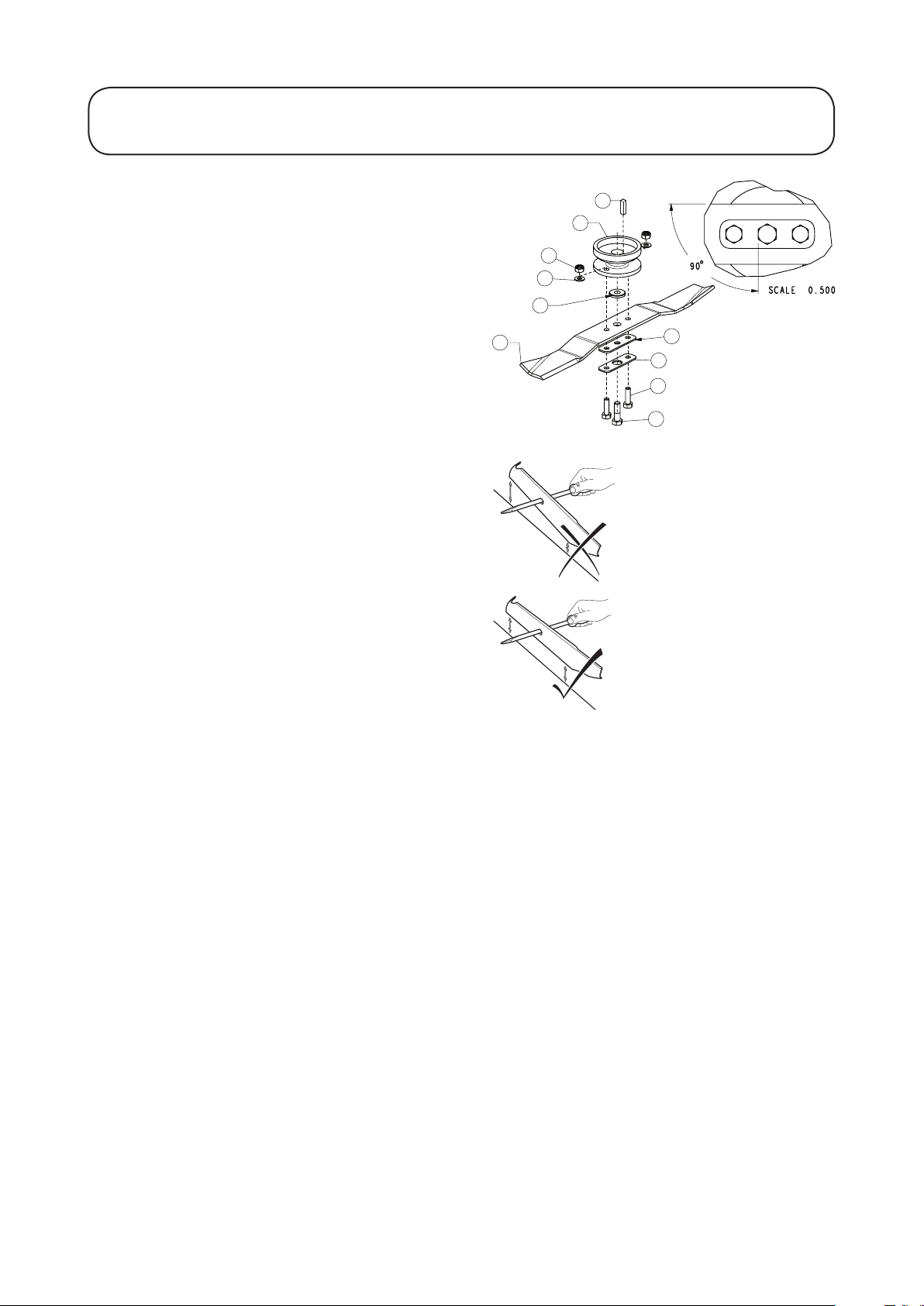
CUTTERBAR
5
2
4
1
3
6
8
7
10
9
1.57 1.57
MAINTENANCE
Cutterblades
1. Bolt M12*40 HT/10.9
2. Lockplate - R3240T blade bolt
3. Nut M10*1.5 nyl ins
4. Screw M10*35
5. Lockplate spacer (zine)
6. Washer M10*21*1.45 Form B
7. Cutterbar spacer
8. Boss cutterbar mounting
9. Key
10. Cutterbar
Regularly check that the cutterblade securing bolts
(items 1 and 2) are tightened to the specied torque
and re-new cutterblade - lockplate.
Bolt (item 1) - Torque to 70-95Nm (52-70 Ibf.ft).
Bolt (item 2) - Torque to 40-55Nm (30-40 Ibf.ft).
Ensure that each cutterblade is balanced. Use a
screw driver with a round shaft to support the cutterblade through its centre hole. Hold the cutterblade horizontal and then release. A balanced cutterblade will remain horizontal. If the cutterblade is
not balanced the heavy end will rotate downwards.
Regrind the heavy end until the cutterblade is correctly balanced.
Page 58

1.58 1.58
MAINTENANCE
Raising the Mower off the Ground
WARNING: PREVENT ACCIDENTS - Before raising the mower ensure that:
The lifting device to be used is in good condition and capable of supporting the weight of the mower
securely. Minimum lift capacity 2500 Kg (2.5 tons).
- The mower is on level ground.
- The parking brake is applied.
- The engine is switched off and the ignition key removed.
- The ground under the lifting device is level and rm.
- The lifting device is secure against one of the mowers lifting points.
If raising the front of the mower, both of the rear wheels must be chocked securely to prevent the
mower rolling away. Note that the parking brake only operates on the front wheels.
WARNING: PREVENT ACCIDENTS - When the mower is raised off the ground:
- NEVER crawl under the mower.
- NEVER start the engine.
Lifting points
Towing Eye
Page 59

2
1
2
3
45
Bypass Valve
1.59 1.59
MAINTENANCE
Towing The Mower
Towing procedure:
Connect a rigid tow bar between the towing eye on
the mower and a suitable towing vehicle. Ensure
that the towing vehicle specication is suited to
braking the combined vehicle weight to rest whilst
effecting complete control at all times. Ensure
that the towing vehicle’s parking brake is applied.
Chock the mower front wheels to prevent the
mower rolling away.
De-commission the front wheel motor disc brakes
as follows :-
1. Identify the right hand front wheel motor disc
brake assembly and remove the rubber plug
(item 2). Position a M12 x 40mm long setscrew
(item 5) with washer (item 4) through the brake
release bar (item 3) and into the hole in the
centre of the motor end plate. Tighten the set
screw (item 5) into the threaded hole in the
brake piston until the brake is released.
2. Identify the left hand front wheel motor disc
brake assembly and repeat the previous
procedure.
De-commission the hydraulic service braking
system as follows:-
Open the transmission bypass valve situated as
shown on top of the transmission pump. The valve
is fully open at 3 anti-clockwise revolutions. Do
not open the valve past 3 revolutions.
The steering must be operated manually when the
mower is being towed. The steering will feel heavy
as there is no hydraulic assistance when the engine
is switched off.
The mower is now in a freewheel condition and
can be towed for a short distance at slow speed.
Remove wheel chocks before towing.
After towing the mower:
To return the mower to its normal working
condition the following procedure must be adopted.
Chock the front wheels and re-commission the
hydraulic service braking system as follows :-
1. Close the transmission bypass valve. Turn
clockwise and tighten to a torque of 48 Nm
(30 lbf.ft) - 52 Nm (38 lbf.ft).
1. Front wheel motor - 950620
2. Hex Plug - 950639
3. Brake release bar
4. Washer - M12 - 09485
5. Setscrew M12 x 40 - ZDH1L040U
Page 60

1
2
3
45
1.60 1.60
MAINTENANCE
Towing The Mower continued
Re-commission the front wheel motor disc brakes
as follows :-
1. Identify the right hand front wheel motor disc
brake assembly. Rotate the setscrew (item
5) anti-clockwise and remove together with
washer (item 4) and brake release bar (item 3).
Reassemble the rubber plug (item 2) into the
motor end plate.
2. Identify the left hand front wheel motor disc
brake assembly and repeat the previous
procedure.
Store the brake release bars, washers and setscrews
(items 3, 4 and 5) for future use.
Remove the wheel chocks.
Disconnect the tow bar.
The mower braking system will now operate in the
normal way.
WARNING: PREVENT ACCIDENTS - Before
using the mower, ensure that the braking system
operates correctly. Carry out initial checks with
the mower at slow speed.
Do not operate the mower with a defective
braking system.
Do not operate the mower with the brakes
de-commissioned.
1. Front wheel motor
2. Rubber plug
3. Brake release bar
4. Washer - M12
5. Setscrew M12 x 40
Page 61

1.61 1.61
FAULT POSSIBLE CAUSE REMEDY
GRASS CUTTING FAULTS
Areas of uncut grass at
point of overlap between
cutterdecks
Step in cut grass height at
point of overlap between
cutterdecks
Turning too tightly Increase turning radius
Mower sliding sideways when
travelling across face of slope
One end of cutterdeck out of ground contact
caused by:
- Poorly routed hoses or wrongly
positioned hydraulic adaptors
- Pivot pins seizing Free off and grease pivot points
- Grass build up under cutterdeck Remove grass
Inconsistent height of cut settings between
the cutterdecks
Raise/lower position control not in oat
position
One end of cutterdeck out of ground contact
caused by:
- Poorly routed hoses or wrongly
positioned hydraulic adaptors
- Pivot pins seizing Free off and grease pivot pins
- Grass build up under cutterdeck Remove grass
Mow up/down slope
Reroute hoses/reposition hydraulic adaptors
Check and readjust height of cut
settings
Operate position control to oat
position
Reroute hoses/reposition hydraulic adaptors
Some uncut or poorly cut
strands of grass
Scalping Undulations too severe for height of cut
Undulating ground contours Change direction of cut
Cutterdecks worn or damaged Sharpen or replace as necessary
Height of cut is too high Lower height of cut setting
Cutting edges of cutterdecks/
bottom blades are rounded
Cutterblades out of balance Replace as necessary
Cutterdeck gauge wheels damaged Inspect and replace as necessary
Inconsistent height of cut settings Check and readjust height of cut settings
Slow cutterblade rotational speed Refer to TROUBLE SHOOTING
setting
Height of cut too low Raise height of cut
Back lap or regrind to restore cutting edges
Use oating cutterdecks
Page 62

1.62 1.62
When using the following chart it may be found that overhaul of major components or hydraulic
pressure adjustments are necessary. In this case it is recommended that your authorised dealer make
these repairs as they are properly equipped to do this work.
WARNING: PREVENT ACCIDENTS - ALWAYS Apply the parking brake, switch off the engine
and remove the ignition key before attempting to work on the mower.
FAULT POSSIBLE CAUSE REMEDY
TROUBLE SHOOTING
Engine will not start with
ignition key
For all other engine problems; refer to ENGINE HANDBOOK
Differential lock non
operational
Flat battery Terminal connection loose or corroded Clean and tighten terminal connections.
Transmission neutral interlock switch not
energised
Parking brake interlock switch not
energised
Cutterdeck drive interlock switch not
energised
Faulty electrical connection Trace and correct fault
Defective switch Check switch and replace if necessary
Defective solenoid valve Service or replace solenoid valve
Defective wiring Check wiring/connections as necessary
Remove foot from forward/reverse pedals
Check telltale indicators
Check setting of transmission neutral interlock switch
Operate parking brake lever to the ON
position
Check telltale indicators
Check setting of parking brake interlock
switch
Move cutterdeck drive switch to the OFF
position
Check telltale indicators
Check setting of cutterdeck interlock switch
Recharge battery
Loose or defective alternator belt Re tension or replace drive belt, refer to
ENGINE HANDBOOK
Defective battery Recharge battery
Replace battery
Electrical short circuit Trace short circuit and make good
Hydraulic oil system
overheating
Incorrect brake operation Faulty wheel motor brake assembly Consult your authorised dealer
Blocked radiator screen Clean screen
Blocked oil cooler matrix Clean oil cooler matrix
Blocked engine radiator matrix Clean matrix
Low relief valve setting Have relief valve cleaned and pressure
checked. Consult your authorised dealer
Low oil level Fill reservoir to correct level
Brakes engaged Disengage brakes
Defective fan or fan drive Check fan operation and service required
Worn brake discs Replace brake discs
Consult your authorised dealer
Page 63

1.63 1.63
FAULT POSSIBLE CAUSE REMEDY
Lack of steering Defective steering valve Service or replace steering valve
Defective hydraulic cylinder Service or replace hydraulic cylinder
Damaged steering hose Replace defective hose
TROUBLE SHOOTING
Lack of transmission
drive
Forward/backward
transmission creep in
neutral
Work/transport modes
non-operational
Excessive noise in
hydraulic system
Parking brake engaged Release parking brake
Low oil level Fill reservoir to correct level
Incorrect oil used Drain reservoir and rell with correct oil
Defective travel pedal linkage Check linkage and replace defective parts
Defective transmission pump Have the transmission pump overhauled by
your authorised dealer
Transmission relief valve open Close relief valve, refer to
MAINTENANCE - TOWING THE
MOWER
Broken drive coupling Replace drive coupling
Transmission lter blocked Replace transmission lter
Transmission neutral adjustment incorrectly
set
Defective control switch Check switch and replace if necessary
Defective solenoid valve Service or replace solenoid valve
Defective wiring Check wiring connections and repair/replace
Faulty pump Identify noisy pump and service or replace
Faulty motor Identify noisy motor and service or replace
Readjust transmission neutral setting
as necessary
Air leaking into system Tighten or replace hydraulic ttings
particularly in suction lines
Suction strainer blocked or damaged Clean and replace suction strainer or renew
as necessary
Excessive oil viscosity due to cold
conditions
Low relief valve setting Have relief valve cleaned and pressure
Low hydraulic oil level Fill hydraulic oil reservoir to correct level
Allow system to warm up
checked. Consult your authorised dealer
Page 64

1.64 1.64
FAULT POSSIBLE CAUSE REMEDY
TROUBLE SHOOTING
After initial satisfactory
operation machine loses
power.
One cylinder rotates
slowly
Cutterdeck fails to lift out
of work
Worn pump or motor Replace as necessary
Low hydraulic oil level Fill hydraulic oil tank to correct level
Incorrect oil viscosity Renew oil in hydraulic tank with hydraulic
oil of correct viscosity grade, refer to
SPECIFICATIONS
Oil lter element blocked Change lter element
Faulty pressure relief valve Have relief valve cleaned and pressure
checked. Consult your authorised dealer
Overheating Reduce work rate i.e. increase height of cut
or reduce forward speed
Incorrect hydraulic oil grade, refer - Problem
‘Hydraulic Oil System Overheating’
Leaks on suction hose Check and tighten ttings. Replace hose if
necessary
Motor integral check valve jammed open Have check valve cleaned and checked
Motor worn Replace motor
Lift cylinder seal failure Replace seals
Pressure relief valve jammed open or
wrongly set
Have relief valve cleaned and pressure
checked. Consult your authorised dealer
Cutterdecks do not follow
ground contours
Cutterdeck vibrate
excessively
Cylinders rotate in wrong
direction
Defective control valve Overhaul control valve
Mechanical blockage Remove blockage
Incorrect hose routing or incorrect
orientation of hydraulic ttings
Tightness in pivots Free off and grease as necessary
Mower operated in ‘hold’ position Move position control lever to ‘down/oat’
Cutterblades out of balance Re sharpen or replace as necessary
Hoses wrongly connected Check hydraulic circuit and re connect as
Cutterdeck drive switch wrongly connected Check switch electrical connections
Move cutterdecks throughout extremes of
movement and observe any tightness in the
hoses. Correctly route hoses and orientate
ttings as necessary
position
necessary
Page 65

1.65 1.65
FAULT POSSIBLE CAUSE REMEDY
TROUBLE SHOOTING
Cutterdecks fail to start
up when lowered into
work
Faulty seat sensor switch Check mechanical and electrical operation
of switch
Low oil level Fill hydraulic oil reservoir to correct level
Faulty shut off sensor switch Check mechanical adjustment and electrical
operation
Pressure relief valve jammed open or
wrongly set
Cutterblade jammed Free off as necessary
Cutterdeck control valve in the ‘off’ position
caused by:
- Defective control valve Overhaul control valve
- Electrical fault Have electrical system checked
Have relief valve cleaned and pressure
checked. Consult your authorised dealer
Contact your Toro dealer if you have a problem which is not outlined above.
Page 66

20
22
9
34
35
36
37
26
G/P
B
58
L
L
B
G/P
L
Y/B
Y/B
W/B
56
P/R
P/R
Y/B
58
G/P
P/R
O
O
L/Y
L/Y
P/Y
B
2
31
N/W
W
NB
G/U
N
R
W
U
U/G
N/R
R
1
3 4
5
6
P/R
W/R
W/R
N
B
B
W/G
N/W
W/B
G/N
O
W/B
UG
B
17
UB
16UY18
19 UY
54 UB
55 UG
30
15
58
19
17
23
25
27
28
COLOURS
B - BLACK
N - BROWN
R - RED
O - ORANGE
Y - YELLOW
G - GREEN
U - BLUE
P - PURPLE
S - SLATE
W - WHITE
K - PINK
L - LIGHT GREEN
B
R
U
G
G
B
R
U
L
L
N/B
N/W
B
N/W
N/B
N/W
P/BP/Y
P/R
P/Y
P/B
R/S
50a
33
40
B
R/W
O
B
B
R/W
33
41
44 45
46
47
48
43
49
51
52
50
33
33
Braid
B
W/R
B
R/W
G/R
G/W
B
B
G/R
B
G/W
W/Y
P/R
U/R
B/P
N/W
W/N
R
N
W/R
N
N/Y
G/U
N/B
N
B
1
2
24
N/B
56
B
N
10
12
11
13
14
8
7
P/R
P/R
P/R
W/P
W/Y
W/N
N/Y
N/B
B/P
W/U
L/Y
B/P
W/U
R/S
L/Y
21
15
38
39
42
P
P/R
P
N/R
N
R
W/R
W/P
B
W/U
B
P/B
U/R
1 2 3 4 5 6 7 8
53
N
L
U/R
31 49
49a
1.66 1.66
ELECTRICAL CIRCUIT DIAGRAM
Page 67

1.67 1.67
Item no Description Part No Qty
1. Switch - Parking Brake Interlock 950865
2. Glow Plug Timer 15694-65992
3. Light - Parking Brake 924601/950858
4. Light - Glow Plugs 924601/950857
5. Light - Neutral 924601/950862
6. Light - Cutterdeck Drive Off 924601/950861
7. Light - Return Filter 924601/950866
8. Light - Pressure Filter 924601/950863
9. Light - Battery Warning 924601/924605
10. Light - Engine Oil Pressure 924601/924606
11. Light - Engine Coolant Temperature 924601/924602
12. Light - Hydraulic Oil Temperature 924601/924603
13. Diodes - Overheat - Audible Warning 950868
14. Switch - Beacon (supplied with beacon kit) 924608
15. Switch - Work/Transport Mode 924607
16. Solenoid - LH Cutterdeck Drive 70-06-246
17. Solenoid - Centre Cutterdeck Drive 70-06-246
18. Solenoid - RH Cutterdeck Drive 70-06-246
19. Switch - RH Deck Interlock 994865
20. Switch - Cutterdeck Drive 511.106 924607
21. Fusebox 70-09-096
1. 10A Cutter Drive & Lift Conguration 70-09-026
2. 10A Transmission & Horn 70-09-026
3. 3A Instruments 70-09-024
4. Blank (Beacon) -
5. Blank (Cab Wipers) or (Air Suspension Seat) -
6. Blank (Lighting Kit) -
7. Blank (Lighting Kit) -
8. 30A Engine Start (Fuel Solenoid) 70-09-027
22. Switch - Ignition 74-09-009
23. Switch - Horn 924618
24. Fuse - Engine Glow Plugs 60A 950926
25. Relay - Overheat Audible Warning 70-09-148
26. Diode - Seat Switch 950868
27. Relay - Glow Plugs 924625
28. Timer - Operator Presence Interlock 70-01-512
29. Diode - Parking Brake 950868
30. Relay - Seat Switch 70-09-148
32. Temperature Gauge (supplied with temp kit) -
33. Connectors for Lighting Kit -
34. Horn 70-09-108
35. Switch - Operator Seat 953819
36. Solenoid - Differential Lock 910627
37. Switch - Differential Lock 994860
38. Switch - Pressure Filter -
39. Switch - Hydraulic Oil Temperature 940852
40. Connection for Beacon Kit -
41. Switch - Neutral/Starter Interlock 111-0143
42. Battery 70-09-015
43. Switch - Engine Oil Pressure -
44. Starter Motor -
ELECTRICAL CIRCUIT DIAGRAM
Page 68

1.68 1.68
Item no Description Part No Qty
45. Alternator/Regulator -
46. Engine Temperature Sender (supplied with temp kit) -
47. Glow Plugs -
48. Switch - Engine Overheat -
49. Solenoid - Fuel -
50. Engine V2003 M-T 994800
51. Hour meter 910850
52. Switch - Return lter -
53. Solenoids - Work/Transport Mode 910627
54. Switch - LH Deck Interlock 994865
55. Switch - Centre Deck Interlock 994865
56. Fuse -Main 60A 950926
58. Delay Module - Seat 924722
ELECTRICAL CIRCUIT DIAGRAM
Page 69

23
1.69 1.69
TRANSMISSION/BRAKE HYDRAULIC CIRCUIT DIAGRAM
Page 70

1.70 1.70
Item no Description Part No
1 Motor - Front Wheel Twinlock - 332cc/Rev 953686
2 Motor - Front Wheel Twinlock - 332cc/Rev 953682
3 Manifold - Front Transmission 953683
4 Valve - Solenoid - Work/Transport 5 Valve - Pilot Operated - Diff Lock -
6 Relief Valve - Serial Lines - 80 bar -
7 Valve Solenoid - Diff Lock -
8 Relief Valve - Front Motor - 375 Bar 9 Flow Divider - Front Wheels -
10 Valve - Pilot Operated - Diff Lock 11 Shuttle Valve - Hot Oil Purge 953687
12 Relief Valve - Hot Oil Purge -
13 Relief Valve - Serial Line - 375 Bar 953710
14 Wheel Motor - Rear - 130cc/Rev 953685
15 Pump - Transmission - 52cc/Rev 953684
16 Relief Valve - Charge Pump - 29 Bar -
17 Relief Valves - Fwd/Rev - 350 Bar 18 Oil Cooler 950606
19 Filter - Charge - 10 Micron 950597
20 Filter - Return - 10 Micron 924865
21 Hydraulic Oil Tank 953802
22 Check Valve - Transmission Fwd/Rev 23 Suction Strainer - 125 Micron 950608
24 Valve - Brake 70-06-015W
25 Check Valve 26 Orice - 1.5mm Dia. 27 3/8 Check Valve 2302 65-06-303
28 1/4 Check Valve 74-06-016
TRANSMISSION/BRAKE HYDRAULIC DIAGRAM
Page 71

18
21
19
19
20
21
17
16
15
9
11
10
12
13
14
25
24
23
22
27
26
32
30
31
31
29
28
32
6
6
8
8
8
7
8
7
6
8
8
7
8
7
A3
B3 P3 A1
B1
P2
A2
B2 R
TC
T
T2
T3
0201
1.71 1.71
HYDRAULIC CIRCUIT DIAGRAM
Page 72

1.72 1.72
Item no Description Part No
1 Gear Pump – Triple – Cutters & Lift 950712
2 Relief Valve – Steering & Lift – 120 bar 3 Cutterdeck Left 4 Cutterdeck Centre 5 Cutterdeck Right 6 Cutter Motor Clockwise viewed on shaft end (Qty 3) 950714
7 Cutter Motor Counter Clockwise viewed on shaft end (Qty 4) 950713
8 Check Valve / Orice – Motor Bypass (Qty 7) -
9 Steering Unit 910649W
10 Check Valve – Steering Shock Bypass R.H. 11 Check Valve – Steering Shock Bypass L.H. 12 Relief Valve – Steering Shock L.H. 13 Relief Valve – Steering Shock R.H. 14 Steering Cylinder – Rear Axle 70-01-195W
15 Spool Valve – Cutterdeck Lift LH 16 Spool Valve – Cutterdeck Lift Centre 17 Spool Valve – Cutterdeck Lift RH 18 Hydraulic Cylinder RH Wing Cutterdeck 66-06-001W
19 Hydraulic Cylinder Centre Cutterdeck (Qty 2) 910109W
20 Hydraulic Cylinder LH Wing Cutterdeck 66-06-001W
21 Orice (1.4mm) – Wing Cutterdeck, Hydraulic Cylinder 65-06-019
22 Cutter Drive Manifold 950715
23 Solenoid Valve – Centre Cutterhead Drive 950611
24 Solenoid Valve – Left Cutterhead Drive 950611
25 Solenoid Valve – Right Cutterhead Drive 950611
26 Relief Valve – Centre Cutterhead – 250 Bar 27 Relief Valve – Left/Right Cutterhead – 250 Bar -
28 Oil Cooler 994820
29 Return Filter – Bypass Check Valve – 2 Bar 924865
30 Hydraulic Oil Tank 994802
31 Suction Strainer 950608
32 Check Valve – Oil Cooler Bypass -
HYDRAULIC CIRCUIT DIAGRAM
A Drains From Rear Motor Wheel Motors
B Motor Drains Centre Cutterhead, To Port 8 Transmission Manifold
C Oil Pickup To Transmission Pump
D Oil From Hot Oil Shuttle
Page 73

The Toro Total Coverage Guarantee
A Limited Warranty
Conditions and Products Covered
The Toro®Company and its afliate, Toro Warranty Company, pursuant
to an agreement between them, jointly warrant your Toro Commercial
product (“Product”) to be free from defects in materials or workmanship
for two years or 1500 operational hours*, whichever occurs rst. This
warranty is applicable to all products with the exception of Aerators
(refer to separate warranty statements for these products). Where a
warrantable condition exists, we will repair the Product at no cost to you
including diagnostics, labor, parts, and transportation. This warranty
begins on the date the Product is delivered to the original retail purchaser.
* Product equipped with an hour meter.
Instructions for Obtaining Warranty Service
You are responsible for notifying the Commercial Products Distributor or
Authorized Commercial Products Dealer from whom you purchased the
Product as soon as you believe a warrantable condition exists. If you need
help locating a Commercial Products Distributor or Authorized Dealer, or
if you have questions regarding your warranty rights or responsibilities,
you may contact us at:
Commercial Products Service Department
Toro Warranty Company
8111 Lyndale Avenue South
Bloomington, MN 55420-1196
E-mail: commercial.warranty@toro.com
Owner Responsibilities
As the Product owner, you are responsible for required maintenance
and adjustments stated in your Operator’s Manual. Failure to perform
required maintenance and adjustments can be grounds for disallowing a
warranty claim.
Items and Conditions Not Covered
Not all product failures or malfunctions that occur during the warranty
period are defects in materials or workmanship. This warranty does not
cover the following:
• Product failures which result from the use of non-Toro replacement
parts, or from installation and use of add-on, or modied non-Toro
branded accessories and products. A separate warranty may be
provided by the manufacturer of these items.
• Product failures which result from failure to perform recommended
maintenance and/or adjustments. Failure to properly maintain your
Toro product per the Recommended Maintenance listed in the
Operator’s Manual can result in claims for warranty being denied.
• Product failures which result from operating the Product in an
abusive, negligent or reckless manner.
• Parts subject to consumption through use unless found to be
defective. Examples of parts which are consumed, or used up, during
normal Product operation include, but are not limited to, brakes
pads and linings, clutch linings, blades, reels, bed knives, tines,
spark plugs, castor wheels, tires, lters, belts, and certain sprayer
components such as diaphragms, nozzles, and check valves, etc.
• Failures caused by outside inuence. Items considered to be outside
inuence include, but are not limited to, weather, storage practices,
contamination, use of unapproved coolants, lubricants, additives,
fertilizers, water, or chemicals, etc.
• Normal noise, vibration, wear and tear, and deterioration.
• Normal “wear and tear” includes, but is not limited to, damage to
seats due to wear or abrasion, worn painted surfaces, scratched
decals or windows, etc.
Parts
Parts scheduled for replacement as required maintenance are warranted
for the period of time up to the scheduled replacement time for that part.
Parts replaced under this warranty are covered for the duration of the
original product warranty and become the property of Toro. Toro will
make the nal decision whether to repair any existing part or assembly or
replace it. Toro may use remanufactured parts for warranty repairs.
Note Regarding Deep Cycle Battery Warranty:
Deep cycle batteries have a specied total number of kilowatt-hours they
can deliver during their lifetime. Operating, recharging, and maintenance
techniques can extend
or reduce total battery life. As the batteries in this
product are consumed, the amount of useful work between charging
intervals will slowly decrease until the battery is completely worn out.
Replacement of worn out batteries, due to normal consumption, is the
responsibility of the product owner. Battery replacement may be required
during the normal product warranty period at owner’s expense.
Maintenance is at Owner’s Expense
Engine tune-up, lubrication cleaning and polishing, replacement of
Items and Conditions Not Covered lters, coolant, and completing
Recommended Maintenance are some of the normal services Toro
products require that are at the owner’s expense.
General Conditions
Repair by an Authorized Toro Distributor or Dealer is your sole remedy
under this warranty.
Neither The Toro Company nor Toro Warranty Company is liable for
indirect, incidental or consequential damages in connection with the
use of the Toro Products covered by this warranty, including any
cost or expense of providing substitute equipment or service during
reasonable periods of malfunction or non-use pending completion
of repairs under this warranty. Except for the Emissions warranty
referenced below, if applicable, there is no other express warranty.
All implied warranties of merchantability and tness for use are limited to
the duration of this express warranty. Some states do not allow exclusions
of incidental or consequential damages, or limitations on how long an
implied warranty lasts, so the above exclusions and limitations may not
apply to you.
This warranty gives you specic legal rights, and you may also have other
rights which vary from state to state.
Countries Other than the United States or Canada
Customers should contact their Toro Distributor (Dealer) to obtain guarantee policies for your country, province, or state. If for any reason you are
dissatised with your Distributor’s service or have difculty obtaining guarantee information, contact the Toro importer. If all other remedies fail, you
may contact us at Toro Warranty Company.
1.73 1.73
WARRANTY
Page 74

1.74 1.74
NOTES
Page 75

1.75 1.75
NOTES
Page 76

1.76 1.76
NOTES
Page 77

1.77 1.77
NOTES
Page 78

1.78 1.78
Distributor: Country: Phone Number:
Atlantis Su ve Sulama Sisstemleri Lt Turkey 90 216 344 86 74
Balama Prima Engineering Equipment Hong Kong 852 2155 2163
B-Ray Corporation Korea 82 32 551 2076
Casco Sales Company Puerto Rico 787 788 8383
Ceres S.A. Costa Rica 506 239 1138
CSSC Turf Equipment (pvt) Ltd Sri Lanka 94 11 2746100
Cyril Johnston & Co. Northern Ireland 44 2890 813 121
Equiver Mexico 52 55 539 95444
Femco S.A. Guatemala 502 442 3277
G.Y.K Company Ltd Japan 81 726 325 861
Geomechaniki of Athens Greece 30 10 935 0054
Guandong Golden Star China 86 20 876 51338
Hako Ground and Garden Sweden 46 35 10 0000
Hako Ground and Garden Norway 47 22 90 7760
Hayter Limited (UK) United Kingdom 44 1279 723 444
Hydroturf Int, Co Dubai United Arab Emirates 97 14 347 9479
Hydroturf Egypt LLC Egypt 202 519 4308
Ibea S.P.A Italy 39 0331 853611
Irriamc Portugal 351 21 238 8260
Irrigation Products Int’l Pvt Ltd India 86 22 83960789
Jean Heybroek b.v. Netherlands 31 30 639 4611
Lely (UK) Limited United Kingdom 44 1480 226 800
Maquiver S.A Columbia 57 1 236 4079
Maruyama Mfg. Co. Inc Japan 81 3 3252 2285
Metra Kft Hungary 36 1 326 3880
Mounteld a.s. Czech Republic 420 255 704 220
Munditol S.A. Argentina 54 11 4 821 9999
Oslinger Turf Equipment SA Ecuador 593 4 239 6970
Oy Hako Ground and Garden Ab Finland 358 987 00733
Parkland Products Ltd New Zealand 64 3 34 93760
Prochaska & Cie Austria 43 1 278 5100
RT Cohen 2004 Ltd Israel 972 986 17979
Riversa Spain 34 9 52 83 7500
Roth Motorgerate GmBh & Co. Germany 49 7144 2050
Sc Svend Carlsen A/S Denmark 45 66 109 200
Solvert S.A.S. France 33 1 30 81 77 00
Spypros Stavrinides Limited Cyprus 357 22 434131
Surge Systems India Limited India 91 1 292299901
T-Markt Logistics Ltd Hungary 36 26 525 500
Toro Australia Australia 61 3 9580 7355
Toro Europe BVBA Belgium 32 14 562 960
INTERNATIONAL DISTRIBUTOR LIST
Page 79

1.79 1.79
CUSTOMER INFORMATION
Machine Details
Model: . . . . . . . . . . . . . . . . . . . . . . . . . . . . . . . . . . . . . . . . .
Machine Serial No: . . . . . . . . . . . . . . . . . . . . . . . . . . . . . . . . . . . . . . . . .
Engine Serial No: . . . . . . . . . . . . . . . . . . . . . . . . . . . . . . . . . . . . . . . . .
Cutterdeck Serial No’s: . . . . . . . . . . . . . . . . . . . . . . . . . . . . . . . . . . . . . . . . .
. . . . . . . . . . . . . . . . . . . . . . . . . . . . . . . . . . . . . . . . .
. . . . . . . . . . . . . . . . . . . . . . . . . . . . . . . . . . . . . . . . .
. . . . . . . . . . . . . . . . . . . . . . . . . . . . . . . . . . . . . . . . .
. . . . . . . . . . . . . . . . . . . . . . . . . . . . . . . . . . . . . . . . .
. . . . . . . . . . . . . . . . . . . . . . . . . . . . . . . . . . . . . . . . .
Transmission Pump Serial No: . . . . . . . . . . . . . . . . . . . . . . . . . . . . . . . . . . . . . . . . .
Transmission Valve Block Front Serial No: . . . . . . . . . . . . . . . . . . . . . . . . . . . . . . . . . . . . . . . . .
Cutter Control Valve (Front & Centre) Serial No: . . . . . . . . . . . . . . . . . . . . . . . . . . . . . . . . . .
Cutter Control Valve (Wing) Serial No: . . . . . . . . . . . . . . . . . . . . . . . . . . . . . . . . . . . . . . . . .
Page 80

 Loading...