

Page 1

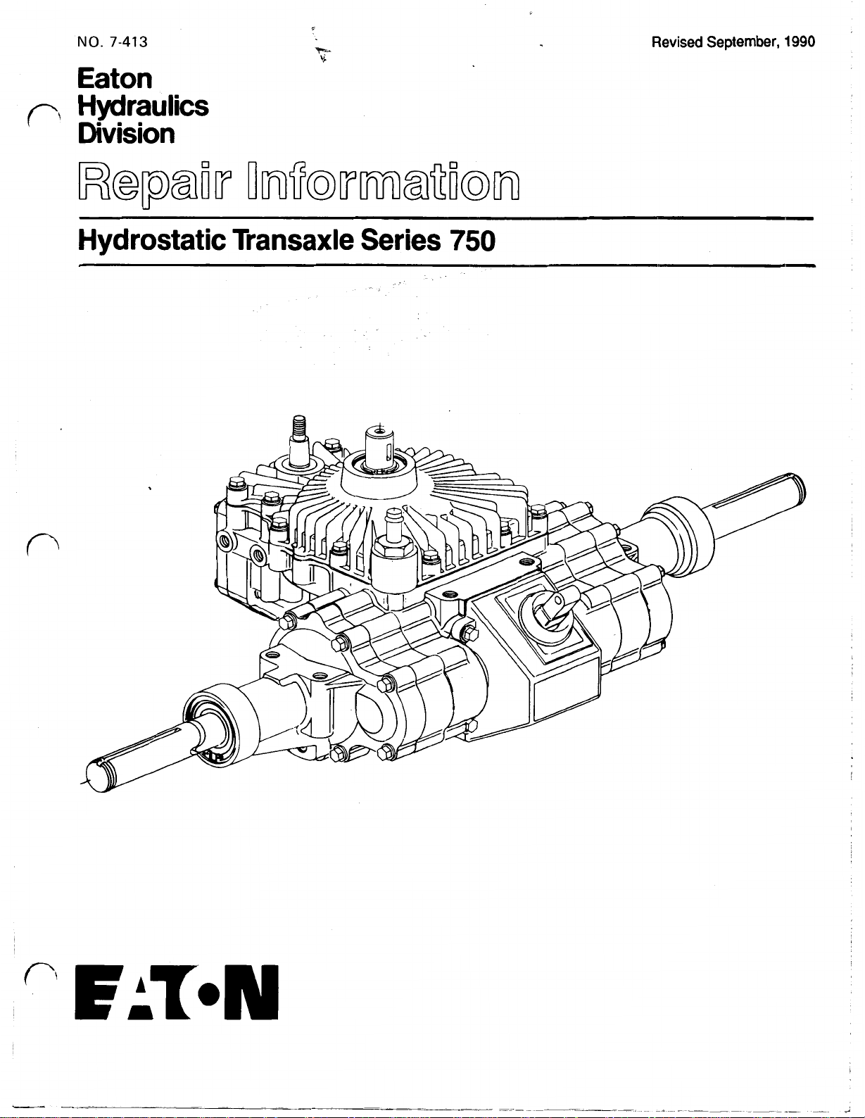
EATON 750, 780 HYDROSTATIC TRANSAXLE
Table of Contents – Page 1 of 1
TRANSAXLE SERIES 750
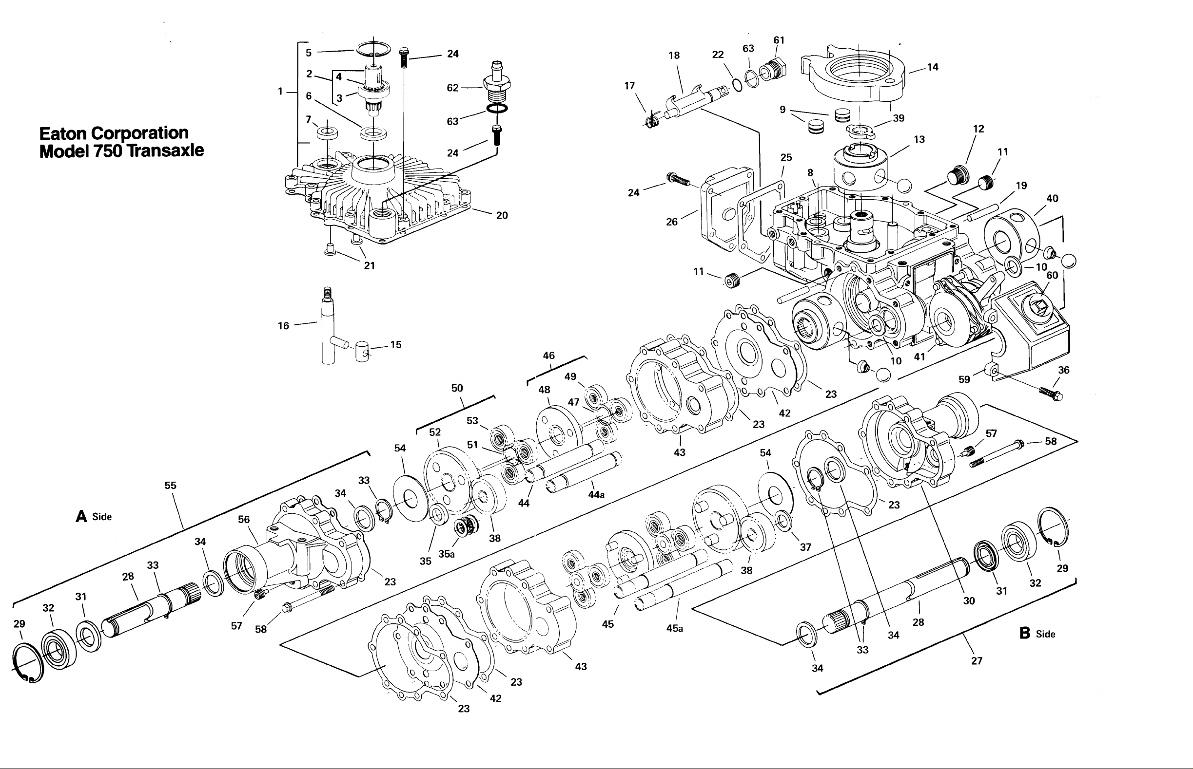
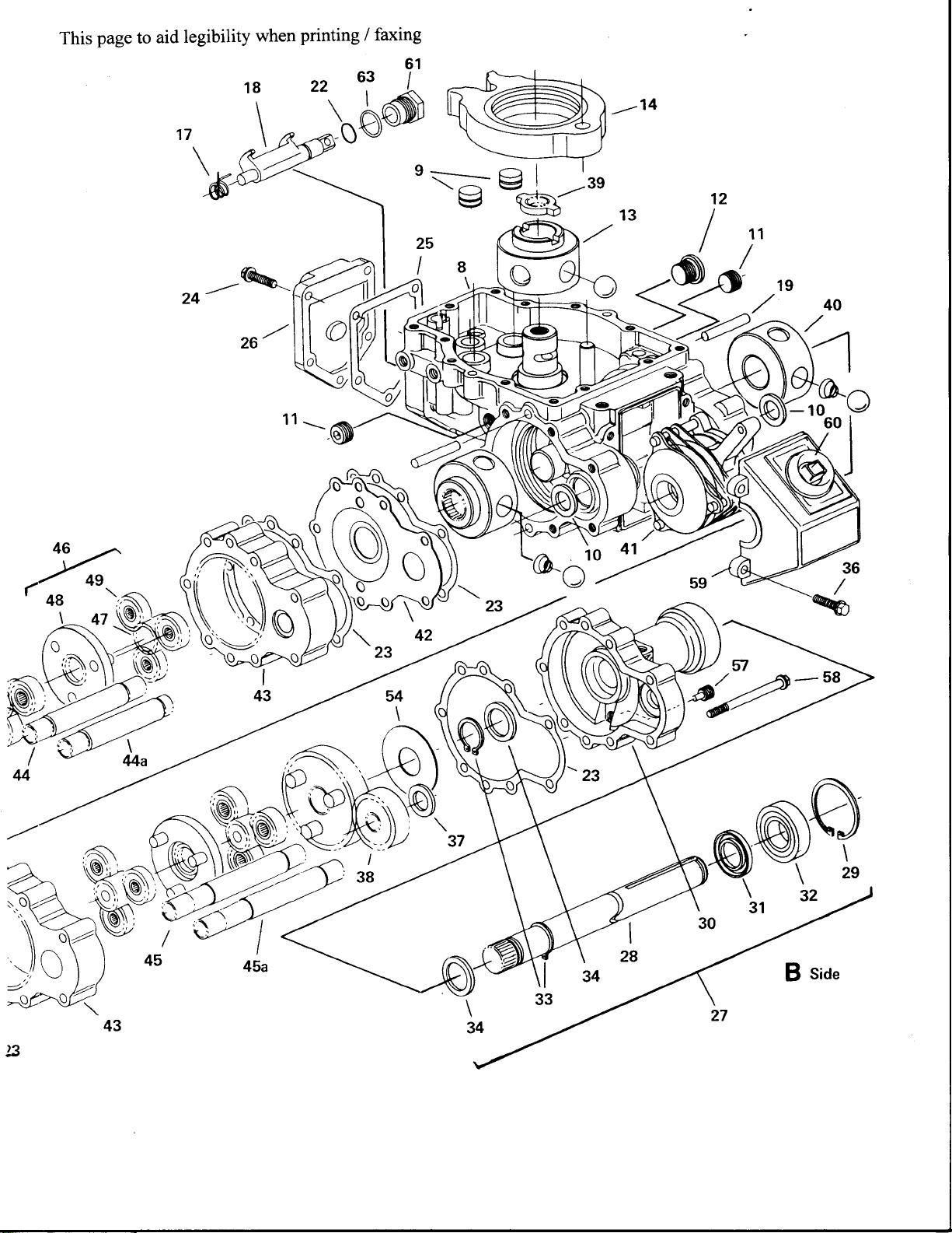
TRANSAXLE PARTS DRAWING
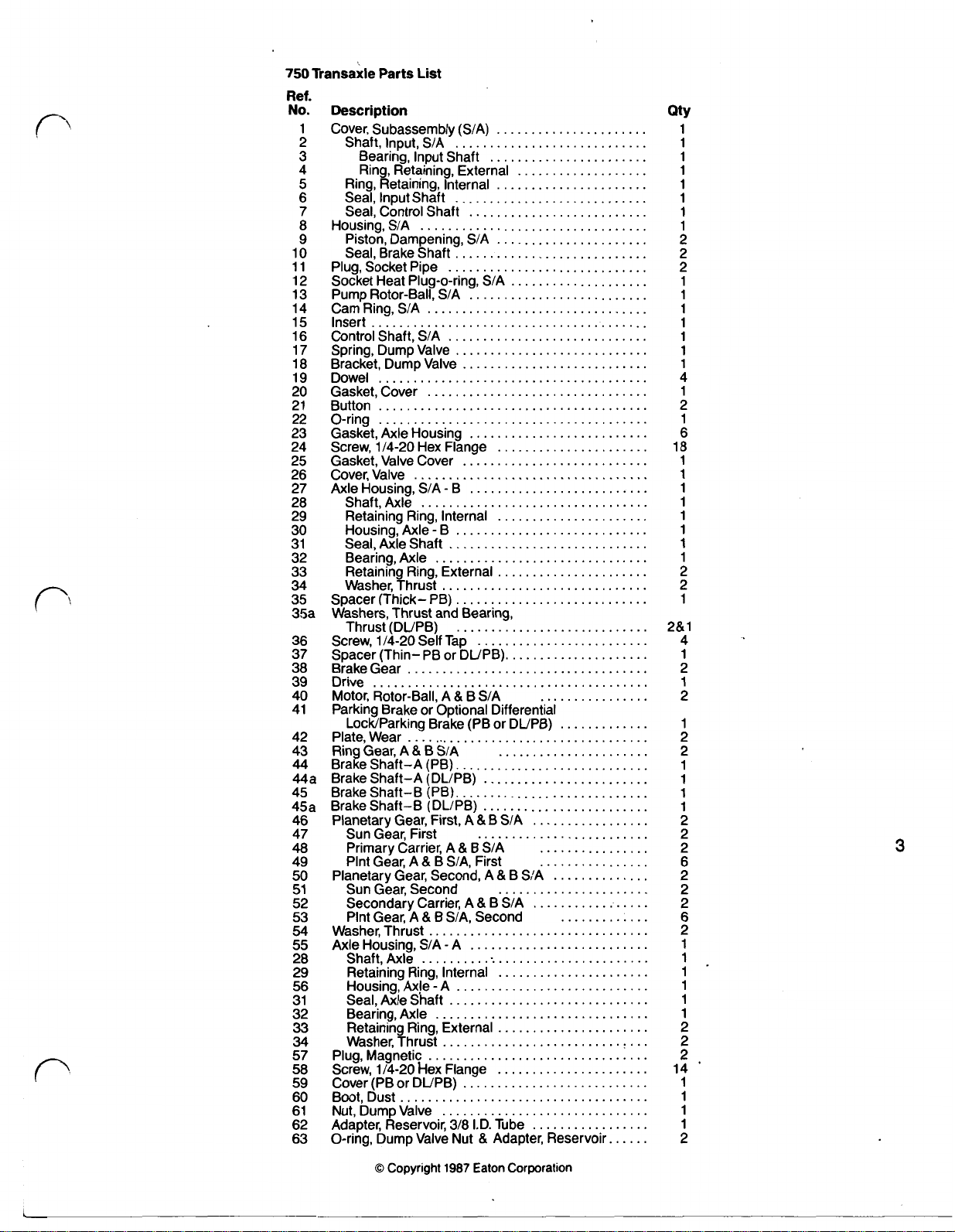
TRANSAXLE PARTS LIST
TOOL REQUIREMENTS
PRODUCT IDENTIFICATION AND ORDERING INFORMATION
COMPLETE DISASSEMBLY
AXLE DISASSEMBLY PROCEDURES
HOUSING DISASSEMBLY PROCEDURES
ROTOR ASSEMBLIES-DISASSEMBLY AND INSPECTION
REASSEMBLY
HOUSING REASSEMBLY
COVER REASSEMBLY
AXLE REASSEMBLY
FLUID RECOMMENDATIONS
TRANSAXLE SERIES 780
FINAL DRIVE REDUCTION OPTIONS - PARTS LIST
TRANSAXLE PARTS DRAWING
TRANSAXLE PARTS LIST
Page 2
NO.
7-413
Hydraulics
Division
Revised
September,
1990
Hydrostatic Transaxle Series
750
Page 3
Page 4

Page 5
Page 6
750
Transaxle Parts List
.
Ref
No
.
Description
1 Cover. Subassembly (S/A)
2 Shaft. Input. S/A
3 Bearing. Input Shaft
4 Ring. Retaining. External
5
Ring. Retaining. Internal
6 Seal. Input Shaft
7
Seal. Control Shaft
8 Housing. S/A
9 Piston. Dampening. S/A
10 Seal. Brake Shaft
11 Plug. Socket Pipe
12 Socket Heat Plug-O-ring. S/A
13 Pump Rotor-Ball. S/A
14 Cam Ring. S/A
15 Insert
16 Control Shaft. S/A
17 Spring. Dump Valve
18 Bracket. Dump Valve
19 Dowel
20 Gasket. Cover
21 Button
22 O-ring
23 Gasket. Axle Housing
24 Screw. 1/4-20 Hex Flange
25 Gasket. Valve Cover
26 Cover. Valve
27 Axle Housing. S/A - B
28 Shaft. Axle
29 Retaining Ring. Internal
30 Housing. Axle - B
31 Seal. Axle Shaft
32 Bearing. Axle
33 Retaining Ring. External
34
35
35a
36 Screw. 1/4-20 Self Tap
37 Spacer (Thin- PB or DL/PB)
38 Brake Gear
39 Drive
40 Motor. Rotor-Ball. A & B S/A
41 Parking Brake or Optional Differential
42 Plate. Wear
43 Ring Gear. A & B S/A
44
44a Brake Shaft-A (DL/PB)
45 Brake Shaft-B (PB)
45a
46 Planetary Gear. First. A & B S/A
47 Sun Gear. First
48
49 Plnt Gear. A & B
50
51 Sun Gear. Second
52 Secondary Carrier. A
53 Plnt Gear, A & B
54
55
28 Shaft. Axle
29 Retaining Ring. Internal
56 Housing. Axle
31
32 Bearing. Axle
33 Retaining Ring. External
34
57 Plug. Magnetic
58 Screw. 1/4-20 hex Flange
59 Cover (PB or DUPE)
60 Boot. Dust
61 Nut. Dump Valve
62 Adapter. Reservoir, 318 I.D. Tube
63 O-ring. Dump Valve Nut
........................................
Washer. Thrust
Spacer (Thick- PB)
Washers. Thrust and Bearing.
Thrust (DL/PB)
........................................
Lock/Parking Brake (PB or DL/PB)
Brake Shaft-A (PB)
Brake Shaft-B (DL/PB)
Primary Carrier.
Planetary Gear. Second. A & B S/A
Washer. Thrust
Axle Housing.
Seal. Axle Shaft
Washer. Thrust
.................................
.............................
................................
.............................
.......................................
................................
.......................................
.......................................
..................................
.................................
.............................
...............................
..............................
...................................
....................................
A
S/A,
S/A,
................................
S/A - A
..................................
-
A
...............................
..............................
................................
....................................
..............................
......................
............................
.......................
...................
......................
............................
..........................
......................
............................
....................
..........................
............................
...........................
..........................
......................
...........................
..........................
......................
............................
......................
............................
............................
.........................
.....................
......................
............................
........................
............................
........................
.................
.........................
&
B S/A
First
......................
&
B
S/A
Second
..................
..........................
......................
............................
.............................
......................
......................
...........................
.................
&
Adapter. Reservoir
................
.............
................
................
..............
.............
......
Qty
1
1
1
1
1
1
1
1
2
2
2
1
1
1
1
1
1
1
4
1
2
1
6
18
1
1
1
1
1
1
1
1
2
2
1
2&1
4
1
2
1
2
2
2
1
1'
2
2
2
14'
1
1
1
1
2
3
©
Copyright
1987
Eaton Corporation
Page 7
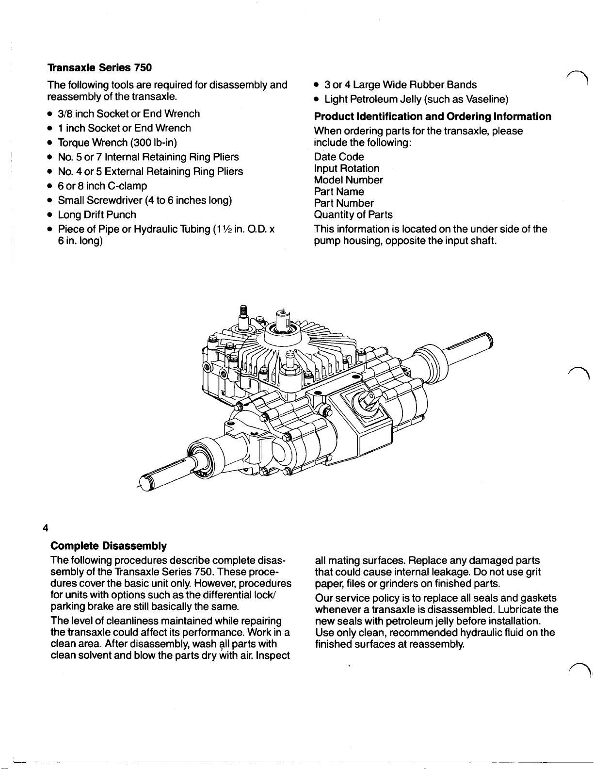
Transaxle Series
The following tools are required for disassembly and
reassembly of the transaxle.
3/8
inch Socket or End Wrench
1
inch Socket or End Wrench
Torque Wrench
No. 5 or 7 Internal Retaining Ring Pliers
No. 4 or 5 External Retaining Ring Pliers
6
or 8 inch C-clamp
Small Screwdriver
Long Drift Punch
Piece of Pipe or Hydraulic Tubing
6
in. long)
750
(300
Ib-in)
(4
to 6 inches long)
(1
½
in. O.D.
x
3
or 4 Large Wide Rubber Bands
Light Petroleum Jelly (such as Vaseline)
Product Identification and Ordering Information
When ordering parts for the transaxle, please
include the following:
Date Code
Input Rotation
Model Number
Part Name
Part Number
Quantity of Parts
This information
pump housing, opposite the input shaft.
is
located on the under side of the
4
Complete Disassembly
The following procedures describe complete disassembly of the Transaxle Series
dures cover the basic unit only. However, procedures
for units with options such as the differential lock/
parking brake are still basically the same.
The level of cleanliness maintained while repairing
the transaxle could affect its performance. Work in a
clean area. After disassembly, wash
clean solvent and blow the parts dry with air. Inspect
750.
These proce-
all
parts with
all mating surfaces. Replace any damaged parts
that could cause internal leakage. Do not use grit
paper, files or grinders on finished parts.
Our service policy is to replace all seals and gaskets
whenever a transaxle is disassembled. Lubricate the
new seals with petroleum jelly before installation.
Use only clean, recommended hydraulic fluid on the
finished surfaces at reassembly.
Page 8
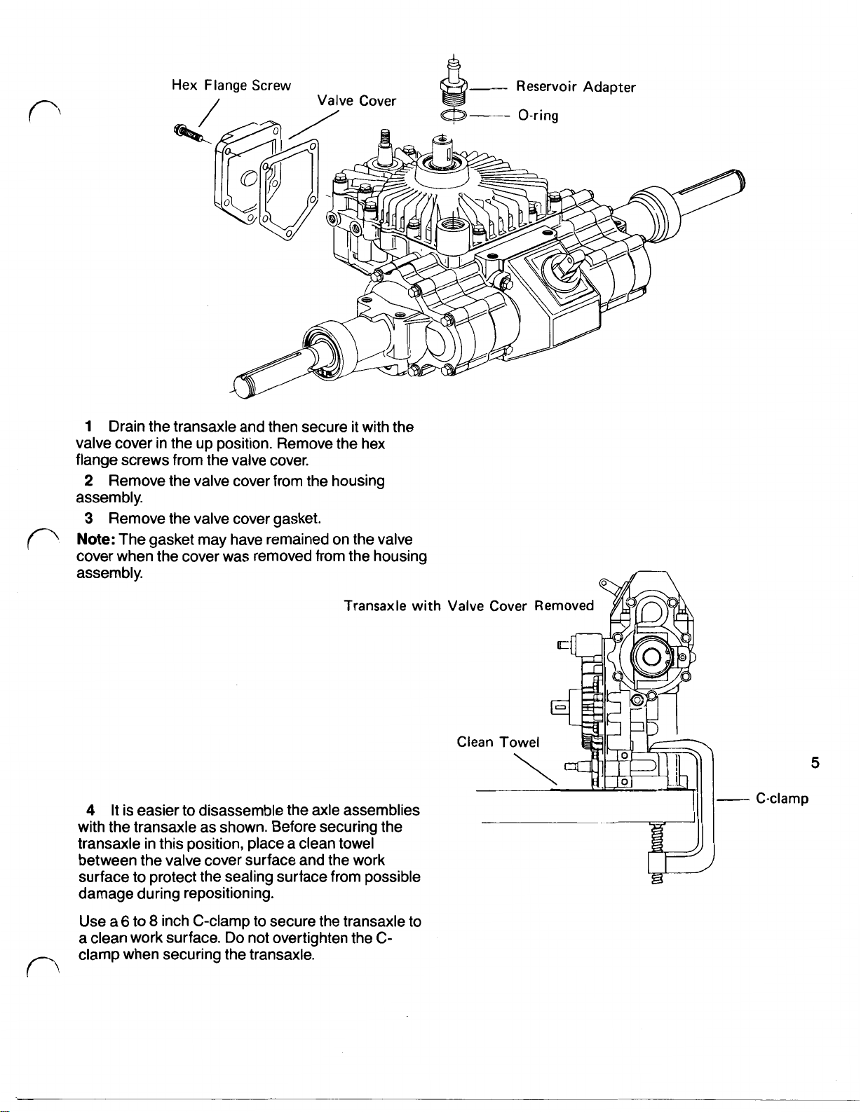
Hex Flange Screw Reservoir Adapter
Valve Cover
1
Drain the transaxle and then secure it with the
valve cover in the up position. Remove the hex
flange screws from the valve cover.
2
Remove the valve cover from the housing
assembly.
3
Remove the valve cover gasket.
Note:
The gasket may have remained on the valve
cover when the cover was removed from the housing
assembly.
Transaxle with
4
It is easier to disassemble the axle assemblies
with the transaxle as shown. Before securing the
transaxle in this position, place a clean towel
between the valve cover surface and the work
surface to protect the sealing surface from possible
damage during repositioning.
6
Use a
to 8 inch C-clamp to secure the transaxle to
a clean work surface. Do not overtighten the Cclamp when securing the transaxle.
5
C-clamp
Page 9
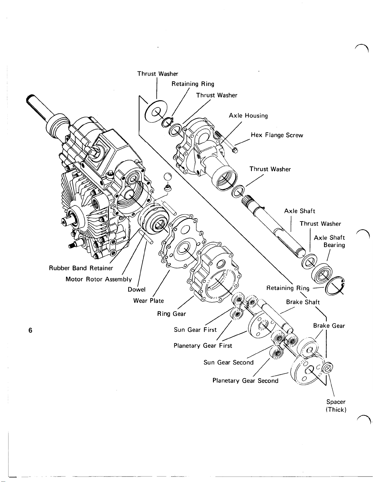
Thrust Washer
Retaining Ring
6
\
Spacer
(Thick)
Page 10

5
Remove the hex flange screws from either axle
assembly.
6 Carefully remove the axle assembly from the
housing assembly.
7 In most cases the brake shaft will remain in the
housing assembly when the axle assembly is
removed.
this time.
Important: Be extremely careful when removing
the motor rotor assemblies. The ball pistons are
spring loaded in the bores and must remain
intact because each ball piston is matched to its
respective bore.
8
blies is to place a separate motor race on top of the
existing motor race in the housing assembly. Hold
the separate race securely in position. Then
carefully pull the motor rotor assembly outward until
the ball pistons are fully engaged
located in the center of the separate race. Carefully
remove the rotor assembly and race together as a
set, handling the motor rotor assembly only.
Note:
a wide rubber band around the outside
rotor to hold the ball pistons in their bores. It is
essential that the ball pistons be retained in their
bores during handling. This is especially true for the
motor rotors, as the motor ball pistons are spring
loaded in the bores.
9 Reposition the transaxle and remove the hex
flange screws from the remaining axle assembly.
10 Carefully remove the axle assembly from the
housing assembly.
11 Remove the remaining brake shaft from the
housing assembly.
12 Using a separate race or wide rubber band to
retain the ball pistons in their bores, carefully remove
the other motor rotor assembly.
If
this occurs, remove the brake shaft at
The best way to remove the motor rotor assem-
in
the groove
If
a separate motor race is not available, work
of
the motor
Axle Disassembly Procedures
13 The following procedures apply to both axle
assemblies.
Remove the axle housing gasket from the wear
plate.
Note: This gasket may have remained on the
housing assembly when the axle assembly was
removed.
14 Remove the wear plate from the axle assembly.
15 Remove the axle housing gasket from the ring
gear assembly.
16 Remove the first sun gear from the primary
carrier assembly.
Note: The first sun gear may have remained in the
motor rotor during removal
17 Remove the primary carrier assembly from the
ring gear assembly.
18 Remove the second sun gear from the
secondary carrier assembly.
19 Remove the ring gear assembly from the axle
housing.
20 Remove the gasket and dowel pins from the
axle housing.
21 Remove the brake gear from the axle housing.
22 Remove the spacer washer from the axle
housing.
23 Remove the secondary carrier assembly from
the axle shaft. Both the primary and secondary
carrier assemblies may be disassembled for
inspection.
24 Remove the large thrust washer from the axle
housing.
of
the axle assembly.
7
Page 11

25
Reposition the axle housing with the splined
4
or
end of the axle in the up position. Use a no.
5
external retaining ring pliers to remove the retaining
ring and thrust washer from the axle shaft.
26
Reposition the axle housing assembly with the
wheel end of the axle in the up position. Use a no.
or
7
internal retaining ring pliers to remove the
5
bearing retaining ring from the axle housing.
27
Remove the axle from the axle housing by
using a small press or by tapping the splined end of
the axle with a plastic tipped hammer. This
will
dislodge the seal and bearing from the axle bore.
28
Press the bearing from the axle shaft. Remove
the seal and thrust washer from the axle shaft. The
thrust washer may have remained in the axle
housing when the axle shaft was removed,
Note:
The retaining ring remaining on the axle shaft
need not be removed.
Page 12

Brake
PB
or
DL/PB
Cover
Self
Tap
Screw
Housing Disassembly Procedures
29 Remove the four self tap screws from the brake
cover.
30 Remove the brake cover from the housing
g
assembly.
31 Remove the PB or DL/PB assembly from the
housing assembly.
32 In most cases further disassembly of the PB or
DL/PB is not necessary.
Page 13

Retaining Ring
Hex
Control Shaft Seal
\
Control Shaft
Dump Valve Nut
O-ring
\
Insert
\
‘I
Input Shaft
Cam Ring S/A
S/A
Sea
I
10
O-ring
Pump Rotor Assembly
Page 14

33 Reposition the housing assembly and remove
the cap screws from the cover assembly.
Note: One of the hex flange screws is located in
the case drain port.
34 Carefully separate and remove the cover from
the housing assembly.
35 To remove the input shaft assembly, first
remove the retaining ring from the input shaft with a
no.
5
or 7 internal retaining ring pliers.
36 Reposition and support the cover with the input
shaft in the down position. Use a plastic hammer or
press to remove the input shaft assembly from the
cover.
37 Remove the input shaft seal from the cover with
a screwdriver.
38 Reposition the cover and then pry the control
shaft seal from the cover assembly with a small
screwdriver.
39 Remove the two buttons from the cam ring
assembly.
Note: These buttons may have remained in the
cover assembly.
40 Remove the cover gasket from the housing.
Note: This gasket may have remained on the cover
when it was removed.
41 Remove the drive from the pump rotor
assembly.
42 Remove the control shaft and insert from the
housing and cam ring assembly.
43 Remove the cam ring insert from the control
shaft.
44 Carefully remove the pump rotor assembly from
the housing, making sure the ball pistons are not
dislodged from their bores.
Important: It is essential that the pump rotor
assembly remain intact during handling as each
ball piston is matched to its respective bore.
45 Install a wide rubber band around the pump
rotor to retain the ball pistons in their bores.
Rotor Assemblies-Disassembly and
Inspection
46 Inspect the rotor assemblies in the following
manner. Remove the piston balls from the rotor, one
at a time, working clockwise from the letter stamped
in the rotor face. Place the piston balls in a container
such as an egg carton or ice cube tray. The balls
must be replaced in the same bores from which they
were removed because they are all select fit.
Check for broken or collapsed springs in the motor
rotor assembly. When broken or collapsed springs
are found with no other irregularities, the springs
complete motor rotor assembly.
journals for irregularities or excessive clearance.
may be replaced individually without replacing the
Inspect the piston balls. They must be smooth and
completely free of any irregularities.
Inspect the rotor bores, rotor bushing and pintle
The ball piston to rotor bore clearance is select fit
electronically from
larities are noted, replace the complete rotor
assembly.
47 Install the pistons in their matching bores. Hold
them in place with a rubber band or separate race.
48 Remove the cam ring assembly from the
housing.
49 The pump and motor journals and cam ring
dowel cannot be removed once they have been
installed in the housing assembly.
Note: Inspect the pump and motor journals for any
irregularities.
replaced as a complete assembly.
50
Reposition the housing assembly and remove
the dump valve nut from the housing assembly.
51 Remove the O-ring from the dump valve nut.
53 Remove the dump valve bracket and spring
from the housing assembly by sliding them over and
lifting upward. Remove the spring from the dump
valve bracket.
54 Remove the O-ring from the dump valve
bracket.
55
Reposition the housing assembly on its side.
Using a long drift punch, remove the brake shaft seal
from the housing. Turn the housing assembly over
and remove the other brake shaft seal.
56 Removal of the check valve assemblies for
inspection
flushing should be all that is required to clean the
check valves.
Removal of the dampening pistons for inspection
cleaning is also not recommended. Once again,
normal flushing should be all that is required for
cleaning.
or
.0002
to
.0006
inch. When irregu-
If
any are found, the housing must be
11
cleaning is not recommended. Normal
or
Page 15

Retaining Ring
Control Shaft Seal
Hex Flange
Cover
Control Shaft
Dump Valve Nut
O-ring
\
Insert
\
‘I
Input Shaft
Cam Ring
S/A
S/A
12
Page 16

Reassembly
57 Before reassembling the Transaxle Series
clean all parts and assemblies with clean solvent
and blow them dry with compressed air. Inspect and
replace all scratched or damaged parts. Replace all
gaskets, shaft seals and O-rings. Lubricate all shaft
seals and O-rings with petroleum jelly (Vaseline) for
retention during assembly. Freely lubricate all
bearings and finished part surfaces with clean
hydraulic fluid to provide lubrication at start-up.
Housing
58 Position the housing assembly on its side.
Lubricate and install the brake shaft seal with the
seal lip pointing away from the housing. Press or
drive the seal into the counterbore.
59 Turn the housing assembly over and repeat the
same procedure for the other brake shaft seal.
60 Lubricate and install the O-ring in the groove
located in the dump valve bracket.
61 Install the spring on the dump valve bracket with
the right angle bend of the spring pointing inward.
62 With the housing assembly in an upright
position, install the spring and dump valve bracket in
the housing assembly. The spring is properly
installed when the longest leg points toward the
check valve assembly.
63 Lubricate and install the O-ring around the
dump valve nut.
64 Install the nut over the dump valve bracket, into
the housing assembly, making sure you do not
damage the dump valve O-ring during installation.
Torque the dump valve nut to
65 Reposition the housing assembly. Install the
cam ring assembly in the housing assembly with the
flush side of the cam ring facing outward.
66 Install the cam ring insert on the control shaft
pivot dowel.
Reassembly
150
Ib-in.
750,
67 Install the control shaft assembly, first aligning
the cam ring insert with the cam ring assembly and
then with the housing assembly.
68 Remove the rubber band from the pump rotor
assembly. Lubricate and install the pump rotor
assembly on the pump journal located in the housing
assembly.
69 install the cover gasket on the housing
assembly.
70
Install the drive in the pump rotor assembly.
Cover Reassembly
71 Lubricate and install the control shaft seal with
the seal lip pointing inward. Press or drive the seal
into the seal counterbore.
72 Lubricate and install the input shaft seal with
the seal lip pointing inward. Press or drive the seal
into the counterbore.
73 Press or drive the input shaft assembly into the
cover.
74 Install the retaining ring on the input shaft,
making sure it is firmly seated in the retaining ring
groove.
75 Apply a small amount of petroleum jelly to the
buttons for retention during assembly. Install the
buttons in the cover assembly.
76 Install the cover assembly by carefully aligning
it with the control shaft, cam ring pivot dowel and
pump rotor drive.
77 After engaging the control shaft and pivot dowel
in the cover assembly, carefully rotate the input shaft
to engage the pump rotor drive. When all mating
parts are aligned and engaged, the cover assembly
should fall into position on the housing assembly.
78 Install the hex flange screws in the cover
assembly and torque them to
125
Ib-in.
13
Page 17

Brake
Shaft
Seal
Brake
Shaft
Seal
79 Before installing the parking brake assembly,
make sure the brake is in the unlocked position.
Note: On transaxles with the differential Iock/parking
brake option, do not move the lever unnecessarily,
especially when it is out of the housing assembly.
The differential lock/parking brake assembly incor-
porates automatic self-adjusting brakes. Unnecessary activation of the lever may cause the brake to
expand and make installation of the assembly very
difficult.
Install the parking brake assembly in the housing
assembly, aligning it with the four notches cast in the
housing assembly.
Note: Make sure the parking brake handle is
pointing
or
leaning towards the cover side of the
housing assembly.
80 To ensure correct installation of the axle
14
housings in the housing assembly, the housing and
axle assemblies are marked with an
A
and
B.
The B
side of the transaxle must be assembled first.
There are two different brake
or
differential shaft
lengths that are used in the axle housing assemblies. The shorter shaft is always used in the
housing, regardless of whether the parking brake
A
axle
or
differential lock option is used. The longer shaft is
always used in the B axle housing assembly.
Apply a small amount of petroleum jelly to the brake
shaft seal. Carefully install the longer of the two
brake shafts in the
B
side of the housing assembly.
Note: Make sure the brake shaft seal is not
damaged during installation.
81 The next step is to engage the brake shaft with
the parking brake. To align and engage the splines,
hold the parking brake disk with one hand and then
rotate the brake shaft slightly with the other hand.
82 Reposition the housing assembly and carefully
install the motor rotor assembly on the motor journal,
into the housing assembly.
Note:
If
a rubber band was used to retain the ball
pistons, remove it now.
83 The first sun gear is longer than the second sun
gear. Install the smaller end of the first sun gear into
the motor rotor assembly.
84 Install the two dowel pins and the first of three
identical gaskets on the B side of the housing
assembly.
85 Install the wear plate, bowed side toward the
motor rotor assembly, aligning it with the two dowels.
86 Install the second of three gaskets on the wear
plate, aligning
it
with the dowels.
87 Install the ring gear assembly on the housing
it
assembly, aligning
with the brake shaft and
dowels.
Caution: The two ring gear assemblies are
identical and can be installed on either side of
the housing assembly. However, when installing
the ring gear assembly, the side with the bearing
must face the axle housing assembly.
88 Lubricate and assemble the three planetary
gears on the primary carrier assembly.
89 Install the primary carrier assembly into the ring
gear assembly by aligning and engaging it with the
previously installed sun gear.
90 Install the second sun gear in the primary
carrier assembly.
91 Lubricate and assemble the three planetary
gears on the secondary carrier assembly.
92 Install the secondary carrier, aligning and
engaging the three planetary gears with the ring
gear assembly and second sun gear.
93 Install the brake gear on the brake shaft.
94 Two different spacer thicknesses are used in
the axle housing assemblies. On transaxles with
parking brakes, the thicker spacer is used in the
A
axle assembly and the thinner spacer is used in the
B axle assembly.
On transaxles with the differential lock/parking brake
option, the A axle housing assembly uses two thin
thrust washers and a thrust bearing to replace the
thick spacer. The
B
axle housing assembly always
uses the thinner spacer, regardless of whether the
parking brake
or
differential lock/parking brake
option is used.
Page 18

For retention during assembly, apply a small amount
of petroleum jelly to the thin spacer. Install the
spacer on the brake shaft and brake gear.
95
Install the third and final gasket on the ring gear
assembly.
Axle
Reassembly
96
Lubricate and install the axle shaft and thrust
washer in the axle housing.
97
Position the axle housing assembly with the
axle end pointing downward. Install the inner thrust
washer and axle shaft retaining ring.
98
Reposition the axle assembly with the output
end pointing upward. Protecting the lip of the axle
Spacer
(Thin)
seal from the retaining ring groove and keyway,
lubricate and install the seal with the lip pointing
inward toward the axle housing.
99
Use a piece of hydraulic tubing
(1
½
in.
O.D.
x
6
in. long) to press the seal into the counterbore.
100
Press the sealed bearing over the axle shaft,
Use
and into the counterbore.
a no. 5 or 7 internal
retaining ring pliers to install the retaining ring in the
axle housing.
101
Reposition the axle housing assembly and
install the large thrust washer on the axle shaft.
102
Install the B axle housing assembly, aligning
and engaging the axle shaft with the secondary
carrier assembly.
Note:
To
ensure correct installation, the axle
housings are marked with the letters
A
and
B.
Each
side of the housing assembly is also marked with an
A
or
B.
Make sure the axle housings are assembled
with the corresponding letters on the housing
assembly.
103
Install the hex flange screws in the housing
and torque them to
125
Ib-in.
15
Page 19

104 Reposition the housing assembly. Apply a
small amount of petroleum jelly to the brake shaft
seal. Carefully install the remaining brake shaft.
105
To
align and engage the brake shaft splines,
hold the parking brake disk with one hand and rotate
the brake shaft slightly with the other hand.
106 Reposition the housing assembly and install
the remaining motor rotor assembly.
107 Install the smaller end of the first sun gear into
the motor rotor assembly.
108 Install the two dowel pins and the first of three
identical gaskets on the A side of the housing
assembly.
109 Install the wear plate with the bowed side
facing the motor rotor assembly, aligning it with the
two dowels.
110 Install the second of three gaskets on the wear
plate, also aligning it with the dowels.
11 1 Install the ring gear assembly on the housing
assembly, aligning it with the brake shaft and
dowels.
Caution: When the ring gear assembly is
installed, the side with the bearing must face the
axle housing.
112 Install the primary carrier assembly in the ring
gear, aligning and engaging it with the previously
installed sun gear.
113 Install the second sun gear in the primary
carrier assembly.
114 Install the secondary carrier, aligning and
engaging the three planetary gears with the ring
gear assembly and second sun gear.
115 Install the brake gear on the brake shaft.
116 Apply a small amount of petroleum jelly to the
spacer for retention. Install the thick spacer on the
brake shaft.
Differential Iock/parking brake option only, apply a
small amount of petroleum jelly to the thrust washers
and bearing for retention during assembly. Install the
thrust washers and bearing on the brake shaft.
Note: At assembly, the thrust bearing must be
positioned between the two thrust washers.
11 7 Install the third gasket on the ring gear
assembly.
118 Install the large thrust washer on the axle
shaft.
11 9 Install the A axle housing assembly, aligning
and engaging the axle shaft with the secondary
carrier assembly.
120 Install the hex flange screws in the housing
and torque them to
125
Ib-in.
121 Reposition the transaxle assembly and install
the cover
(PB
or
DL/PB)
by inserting the lever
through the dust boot.
122 Install the self tap screws in the brake cover
and torque them to
105
Ib-in.
16
Page 20

n
Self Tap Screw
Spacer
(Thick)
17
Page 21

123 Reposition the transaxle assembly and install
the valve cover gasket.
124 Install the valve cover.
125 Install the hex flange screws in the valve cover
and torque them to
Hex Flange Screw Reservoir Adapter
Valve Cover
125
Ib-in.
18
Build Date Code Effective January
Original Build (example
Build Date Code prior to January 1, 1990
A
=January G
B
=
February
C
=March
D
April
E
May
F
=
June
July
H
=
August
I
=
September
J
=October
K
November
L
=
December
01
0190)
x x
1,
1990
Day
01-31
Factory Rebuild (example
01 01 times rebuilt
0101901)
Month Customer Part
(example
L
31
G
=
1986
H = 1987
I = 1988
J
=
1989
J)
-Year
A=1980
B
C
D
E
1981
=
1982
=
1983
=
1984
Latest Date
No.
of
Rebuild
Date
of
Number
of
Rebuilt. (Example
Times Unit has been
Build
Shows
Two
Housing
Times).
Page 22

Fluid Recommendations
A reputable supplier can help you make the best
selection of hydraulic fluid for use in Eaton hydrostatic products.
For satisfactory operation, the following recommen-
dations apply:
1.
The filter system used in the hydraulic circuit
should be capable
the hydraulic fluid to meet
18/13 per SAE J1165. This code allows a
maximum of 2500 particles per milliliter greater
than
5µm
and a maximum of 80 particles per
milliliter greater than 15µm.
2.
At normal operating temperatures, optimum
viscosity ranges are from 80-180
Viscosity should never fall below 60
and, at the lowest expected start-up temperature,
should not exceed
3.
The fluid should be chemically stable, incorporating rust and oxidation inhibitors.
Specific types of fluid meeting these requirements
are:
Premium hydraulic oil; such as Mobil DTE-26
Engine crankcase oil-SAE 2Ow-20, SAE 30 or
40
SAE
Note:
milky, it is possible that a water contaminant problem
exists.
For accurate level readings, take readings when the
fluid is cold.
If
the natural color
of
cleaning and maintaining
IS0
Cleanliness Code
SUS
(16-39 cSt).
SUS
(10
10,000
SUS
(2158 cst).
of
the fluid has become
cSt)
19
Page 23

Eaton Corporation
Eaton G.m.b.H.
Hydraulics
Hydraulics
Division
Division
15151 Highway 5, Eden Prairie,
MN
55344 Telephone
(61
2) 937-9800
100 410 D-5620 Velbert 1 West Germany 49-2051-2070
Printed
In
U.S.A.
FORM
NO. 7-41
July,
1987
3
Page 24

NO. 6-417
Hydraulics
Division
Revised
September,
1990
Hydrostatic Transaxle, Series
780
!
i
I
Page 25

PARTS DRAWING (FOLD OUT) PARTS LIST
13:1
Ref.
No.
Part
51
54
56 990418
57
58
59
60 990406
61
62
63
Ref.
No.
51
54
56
57
58
59
60
61
62
63
No.
104551
1
04341
NSS
NSS
NSS
NSS
NSS
NSS
Part
No.
104073
104341
990405
NSS
NSS
NSS
990406
NSS
NSS
NSS
Description Qty.
Motor, Rotor-Ball, A & B S/A, 15T
Ring Gear, A
Planetary Gear, First, A
Planetary Gear, Second, A B
16:1 Final Drive Reduction
Options
Final Drive Reduction
.
.
. .
.
. .
. . .
.
. . .
. .
.
.
.
. .
.
. .
. .
2
2
2
2
.
2
6
2
.
2
.
.
.
.
.
.
&
B S/A, 54T
Sun Gear, First, 24T
Primary Carrier, A
Plnt Gear, A
Sun Gear, Second,
Secondary Carrier, A
Plnt Gear, A
18T..
Description Qty.
Motor, Rotor-Ball, A & B S/A, 18T
Ring Gear, A
Planetary Gear, First, A
Sun Gear, First, 18T
Primary Carrier, A & B S/A, 18T
Plnt Gear, A
Planetary Gear, Second, A
Sun Gear, Second,
Secondary Carrier, A
Plnt Gear, A
18T..
&
B S/A, First, 15T
&
B S/A, Second,
.
. . .
. . .
. .
&
B S/A, 54T
&
B S/A, First, 18T
&
B S/A, Second,
. . .
. .
. .
&
B S/A
.
. .
. . . . .
&
B S/A, 18T
18T
. . .
&
B S/A
. .
. . . . . . . . . . .
&
B S/A,
.
. . . . . . . .
18T
. . . . . .
&
B
.
. .
. .
. . . . . .
. .
.
&
S/A
. . .
. . . .
&
S/A
. . . . .
.
. . . . .
B S/A
. . .
.
.
2
6
2
2
2
2
2
6
2
2
2
6
Complementary Component
78 104973 Reservoir Assembly for
79 104276
80
104443
81
104946
990474
105636 Adapter, Reservoir,
3/8
in. I.D. Hose-Two Line
.
.
. . .
.
.
. .
Cover
Gasket
Reservoir
23:1 Steel Gear Kit
1
21T Plnt Gear, Second (3)
Secondary Carrier
(Two Kits Required Per Unit)
. . .
5T Sun Gear, Second
.
.
. . . .
. .
.
. . . .
. .
.
. .
3/8
. .
. . . .
(1
I.D. Tube
. . . . .
)
. . . .
.
. .
.
.
. .
. .
. . . . .
.
.
. . . . .
.
. .
.
. . . . .
(1
)
90"
1
.
1
1
1
.
1
Page 26

Page 27

Ref
.
No
.
Part
1
I06071
106073
2
3
NSS
4
NSS
5
101 680-1 56
93955
6
7
93895
8
10471 6
8a
10471 7
9
104294
10581 4*
10
104020
11
103757-088
12
104988
13
104989
14
NSS
NSS
NSS
NSS
NSS
NSS
NSS
NSS
NSS
NSS
NSS
NSS
NSS
15
95653-038
16
104684
17
105660
18
19
20
104664
21
25090-01
22
104435
23
104859-008
24
104943
25
104429
26
10441 3
27
10581 3
28
103621
29
104935
30
104537
No
.
8761 -1 21
8761 -01 3
8785-01
0
0
Description
Cover. Subassembly (S/A)
Shaft. Input. S/A
Bearing. Input Shaft
Ring. Retaining. External
Ring. Retaining. Internal
Seal. Input Shaft
Seal. Control Shaft
Housing. S/A CW (A)
Housing. S/A CW (B)
Piston. Dampening. S/A
Piston. Dampening. S/A
Seal. Brake Shaft (B housing
Only)
......................
Screw. Hex Flange
Washer
Cup. Seal
O-ring
Pluget, Lee
Journal. Pump. S/A
Retainer
Ball. Grade 200
Body, Valve
Dowel. Cam Ring Pilot
Journal. Motor. S/A
Race. Motor
Plug. Socket Pipe
Shaft. Bushing (B Housing Only)
Journal. Motor. RIA
Flange
Screw.
Plug. Socket Pipe
With Dump Valve Option
Spring. Dump Valve
Bracket. Dump Valve
O-ring. Dump Valve Bracket
O-ring. Tube Fitting
Nut. Dump Valve Fitting
Without Dump Valve Option
O-ring Plug. S/A
Protector. Shipping
Clamp. Hose
Adapter. Reservoir. 318 I.D. Tube
Adapter. Reservoir. 318 I.D. Tube
Pump Rotor Ball. S/A
Cam Ring. S/A
Insert
Control Shaft. S/A
Dowel
......................
........................
......................
.......................
¼
..........................
..........................
...............
..........
...............
.............
.............
.............
.............
.....................
...................
............
................
...................
..........
............
...................
..............
............
Hex Socket
...........
................
............
...........
............
.........
...............
...............
....................
.............
..................
...............
Qty.
780
........
.....
........
........
........
.
14
.....
...
...
Ref
.
No .
Part
No
.
Description
2
2
2
2
2
2
2
1
1
4
4
1
2
2
2
2
5
2
4
4
4
2
2
2
2
2
2
2
4
2
2
2
6
2
2
4
4
1
2
2
2
2
2
4
31 105327 Gasket. Cover
32 101597
33 103757-088 Screw. ¼-20 Hex Flange 10
34 104416
35 104393
36 104442 Gasket. Axle Housing
37 104822-008
38 104821 -008
39 10481 5-008 Shaft. Axle
40 101680-206 Retaining Ring. Internal
41 105745 Housing. Axle-B
42 105748 Housing. Axle-A
43 103960 Seal. Axle Shaft
44 104928 Bearing. Axle Shaft
45 103983-098 Retaining Ring. External
46 103966 Washer. Thrust
47 104436-1
48 Spacer
49 103933
50 104107
51 104551 Motor Rotor Ball.
52 104084 Parking Brake Assembly
53 104337
54 104340
55 104596 Shaft. Brake
56 990408 Planetary Gear
57 NSS Sun Gear. First. 15T
58 NSS Primary Carrier. A
59 NSS Plnt Gear. A
60 990409 Planetary Gear. Second.
NSS
61
62 NSS Secondary Carrier.
63
NSS
64
65 103772 Plug. Magnetic
66 103757-275 Screw. ¼-20 Hex Flange
67 104387 Cover. Brake
68 104391 Boot. Dust
69 95862-100 Bolt. 5/16-18 Hex Head
70 95897-031
71 96081-031
72 103222-062 Retaining Ring. External
73 104447 Plug. Seal
74 8761-021 O-ring
75 104730
76 105949-062 Torx Button Head Screw 14
77 105948 Flange
NSS
Not
Sold
Separately
Input Shaft Change from . 750 Dia . to 17mm Dia . Effective Date August
1990
.
Previous parts. cover
shaft seal
able with 17
*
Through Center
(104538).
mm
input shaft parts
Piston. Dampening. S/A ( Wide Band Neutral Not Shown. Has Orifice Hole
)
.
Button 4
Gasket. Valve Cover
Cover. Valve
Axle Housing. S/A-B
Axle Housing. S/A-A
00
Screw. ¼-20 Self-Tap
Gear. Brake 1
Drive
..........................
Plate. Wear 2
Ring Gear.
Sun Gear. Second. 15T
Plnt Gear. A & B S/A, Second.
21T 2
Washer. Thrust
Washer
Nut. Hex
..........................
Dowel 2
..........................
(104410)
.
are subject
input shaft subassembly (103768) and input
to
availability and they are
.
...................
.........................
..........
.............
....................
............
............
............
....................
.........
..............
..............
...............
............
................
.............
.........................
.....................
A
&
B S/A,
..........
.....................
A
&
B S/A,
57T
....................
.
First. A &
B S/A
............
&
B S/A, 15T
&
B S/A, First. 21T
A
&
.........
A
&
B S/A
........................
................
..................
..........
....................
......................
............
........................
........................
..........
......................
..........
.........................
not
Qty
780
........
30
15T
...
........
...
. .
. .
B S/A 2
...
14
1.
interchange-
.
2
2
2
6
1
1
2
2
1
1
2
2
4
4
1
2
2
1
2
1
2
2
2
2
2
2
2
2
1
1
4
8
4
1
1
1
2
The axle housings (Ref
64)
and spacer (Ref
you
must replace the axle housing(s)
.
No
.
No .
.
48)
41
are
and
42)
no
longer used
.
Effective November.
have been redesigned
or
available . If these parts need to
1989
so
the thrust washer (Ref
be
.
No .
replaced
Page 28

HOW
TO
ORDER
REPLACEMENT PARTS
EACH ORDER MUST INCLUDE
THE FOLLOWING INFORMATION
1.
Product Number
2.
Date Code
3.
Part
Name
4.
Part Number
5.
Quantity
of
Parts
Eaton
Corporation
Eaton
G.m.b.H.
Hydraulics
Hydraulics
Division
Division
15151
Highway
100
410
5,
Eden
D-5620
Velbert
Printed
in
Prairie,
1
West
U.S.A.
MN
55344
Germany
Telephone
(612)
49-2051-2070
937-9800
FORM
NO.
July,
6-41
1987
7
 Loading...