

Page 1
FormNo.3373-868RevB
PowerMaxHeavyDuty1128OXESnowthrower
ModelNo.38828—SerialNo.313000001andUp
Operator'sManual
Introduction
Thismachineisintendedtobeusedbyresidential
homeownersorprofessional,hiredoperators.Itis
designedprimarilyforremovingsnowfrompaved
surfaces,suchasdrivewaysandsidewalks,andother
surfacesfortrafconresidentialorcommercial
properties.Itisnotdesignedforremovingmaterials
otherthansnow,norisamodelwithapivotingscraper
designedforclearingoffgravelsurfaces.
Readthisinformationcarefullytolearnhowtooperateand
maintainyourmachineproperlyandtoavoidinjuryand
machinedamage.Youareresponsibleforoperatingthe
machineproperlyandsafely.
YoumaycontactTorodirectlyatwww .Toro.comformachine
andaccessoryinformation,helpndingadealer,ortoregister
yourmachine.
Wheneveryouneedservice,genuineToroparts,oradditional
information,contactanAuthorizedServiceDealerorToro
CustomerServiceandhavethemodelandserialnumbersof
yourmachineready.Figure1identiesthelocationofthe
modelandserialnumbersonthemachine.Writethenumbers
inthespaceprovided.
Figure1
1.Modelandserialnumberlocation
ModelNo.
SerialNo.
Thismanualidentiespotentialhazardsandhassafety
messagesidentiedbythesafetyalertsymbol(Figure2),
whichsignalsahazardthatmaycauseseriousinjuryordeath
ifyoudonotfollowtherecommendedprecautions.
Figure2
1.Safetyalertsymbol
Thismanualuses2wordstohighlightinformation.
Importantcallsattentiontospecialmechanicalinformation
andNoteemphasizesgeneralinformationworthyofspecial
attention.
ReplacementEngineOwner’sManualsmaybeordered
throughtheenginemanufacturer.
Contents
Introduction..................................................................1
Training.................................................................3
Preparation.............................................................3
Operation...............................................................3
MaintenanceandStorage..........................................4
ToroSnowthrowerSafety.........................................4
SoundPressure.......................................................4
SoundPower..........................................................4
Vibration................................................................4
SafetyandInstructionalDecals.................................4
Setup............................................................................7
1InstallingtheUpperHandle....................................7
2InstallingtheWheelClutchCableEnds....................8
3InstallingtheTractionControlLinkage....................9
4InstallingtheChuteControlRod............................10
5ConnectingtheWiretotheHeadlight......................11
6FillingtheEnginewithOil.....................................11
7CheckingtheTirePressure....................................12
8CheckingtheSkids...............................................12
9CheckingtheTractionDriveOperation...................12
ProductOverview.........................................................13
Operation....................................................................14
FillingtheFuelTank...............................................14
StartingtheEngine.................................................14
StoppingtheEngine...............................................16
OperatingtheTractionDrive...................................16
UsingtheWheelClutchLevers.................................17
OperatingtheSpeedSelector...................................17
OperatingtheAuger/ImpellerDrive.........................17
©2012—TheToro®Company
8111LyndaleAvenueSouth
Bloomington,MN55420
Registeratwww.Toro.com.
OriginalInstructions(EN)
PrintedintheUSA
AllRightsReserved
*3373-868*B
Page 2

OperatingtheQuickStick®......................................17
UncloggingtheDischargeChute..............................18
PreventingFreeze-up..............................................18
OperatingTips......................................................19
Maintenance.................................................................20
RecommendedMaintenanceSchedule(s)......................20
PreparingforMaintenance.......................................21
CheckingtheEngineOilLevel.................................21
CheckingandAdjustingtheSkids.............................21
CheckingandAdjustingtheTractionCable................21
CheckingtheAugerGearboxOilLevel......................22
ChangingtheEngineOil.........................................22
AdjustingtheDischargeChuteLatch........................23
ReplacingtheDriveBelts.........................................24
ReplacingtheHeadlightBulb...................................24
Storage........................................................................25
PreparingtheMachineforStorage............................25
RemovingtheMachinefromStorage.........................25
Troubleshooting...........................................................26
2
Page 3

Safety
ThismachinemeetsorexceedstheISOstandard8437
ineffectatthetimeofproduction.
Readandunderstandthecontentsofthismanualbefore
theengineiseverstarted.
Thisisthesafetyalertsymbol.Itisusedtoalertyou
topotentialpersonalinjuryhazards.Obeyallsafety
messagesthatfollowthissymboltoavoidpossibleinjury
ordeath.
Improperlyusingormaintainingthismachinecould
resultininjuryordeath.Toreducethispotential,
complywiththefollowingsafetyinstructions.
Training
•Readtheoperatingandserviceinstructionmanual
carefully.Bethoroughlyfamiliarwiththecontrolsand
theproperuseofthemachine.Knowhowtostopthe
machineanddisengagethecontrolsquickly.
•Neverallowchildrentooperatethemachine.Neverallow
adultstooperatethemachinewithoutproperinstruction.
•Keeptheareaofoperationclearofallpersons,particularly
smallchildren,andpets.
•Exercisecautiontoavoidslippingorfalling,especially
whenoperatinginreverse.
Preparation
•Thoroughlyinspecttheareawherethemachineistobe
usedandremovealldoormats,sleds,boards,wires,and
otherforeignobjects.
•Disengageallclutchesandshiftintoneutralbefore
startingtheengine.
•Donotoperatethemachinewithoutwearingadequate
wintergarments.Wearfootwearwhichwillimprove
footingonslipperysurfaces.
•Handlefuelwithcare;itishighlyammable.
–Useanapprovedfuelcontainer.
–Neveraddfueltoarunningorhotengine.
–Fillfueltankoutdoorswithextremecare.Neverll
fueltankindoors.
–Replacegasolinecapssecurelyandwipeupspilled
fuel.
•Adjustthecollectorhousingheighttocleargravelor
crushedrocksurface.
•Neverattempttomakeanyadjustmentswhiletheengine
isrunning(exceptwherespecicallyrecommendedby
manufacturer).
•Letengineandmachineadjusttooutdoortemperatures
beforestartingtoclearsnow.
•Theoperationofanypoweredmachinecanresultin
foreignobjectsbeingthrownintotheeyes.Alwayswear
safetyglassesoreyeshieldsduringoperationorwhile
performinganadjustmentorrepair.
Operation
•Donotputhandsorfeetnearorunderrotatingparts.
Keepclearofthedischargeopeningatalltimes.
•Exerciseextremecautionwhenoperatingonorcrossing
graveldrives,walks,orroads.Stayalertforhidden
hazardsortrafc.
•Afterstrikingaforeignobject,stoptheengine,remove
thewirefromthespark-plug,thoroughlyinspectthe
machineforanydamage,andrepairthedamagebefore
restartingandoperatingthemachine.
•Ifthemachineshouldstarttovibrateabnormally,stopthe
engineandcheckimmediatelyforthecause.Vibrationis
generallyawarningoftrouble.
•Stoptheenginewheneveryouleavetheoperating
position,beforeuncloggingthecollector/impeller
housingordischargeguide,andwhenmakinganyrepairs,
adjustments,orinspections.
•Whencleaning,repairing,orinspecting,makecertainthe
collector/impellerandallmovingpartshavestopped.
Disconnectthespark-plugwire,andkeepthewireaway
fromtheplugtopreventaccidentalstarting.
•Donotruntheengineindoors,exceptwhenstartingit
andformovingthemachineinoroutofthebuilding.
Opentheoutsidedoors;exhaustfumesaredangerous.
•Donotclearsnowacrossthefaceofslopes.Exercise
extremecautionwhenchangingdirectiononslopes.Do
notattempttoclearsteepslopes.
•Neveroperatethemachinewithoutproperguards,plates,
orothersafetyprotectivedevicesinplace.
•Neveroperatethemachinenearglassenclosures,
automobiles,windowwells,drop-offs,etc.withoutproper
adjustmentofthesnowdischargeangle.Keepchildren
andpetsaway.
•Donotoverloadthemachinecapacitybyattemptingto
clearsnowattoofastarate.
•Neveroperatethemachineathightransportspeedson
slipperysurfaces.Usecarewhenreversing.
•Neverdirectdischargeatbystandersorallowanyonein
frontofthemachine.
•Disengagepowertothecollector/impellerwhenmachine
istransportedornotinuse.
•Useonlyattachmentsandaccessoriesapprovedby
themanufacturerofmachine(suchaswheelweights,
counterweights,cabs,etc.).
•Neveroperatethemachinewithoutgoodvisibilityor
light.Alwaysbesureofyourfooting,andkeeparm
holdonthehandles.W alk;neverrun.
3
Page 4

•Neveroperatethemachinewithoutgoodvisibilityor
light.
•Takeallpossibleprecautionswhenleavingthemachine
unattended.Shiftintoneutral,settheparkingbrake,stop
theengineandremovethekey.
MaintenanceandStorage
•Checkallfastenersatfrequentintervalsforproper
tightnesstobesurethemachineisinsafeworking
condition.
•Neverstorethemachinewithfuelinthefueltankinsidea
buildingwhereignitionsourcesarepresentsuchashot
waterandspaceheaters,clothesdryers,etc.Allowthe
enginetocoolbeforestoringinanyenclosure.
•Alwaysrefertoowner’sguideinstructionsforimportant
detailsifthemachineistobestoredforanextended
period.
•Maintainorreplacesafetyandinstructionslabels,as
necessary.
•Runthemachineafewminutesafterthrowingsnowto
preventfreeze-upofthecollector/impeller.
ToroSnowthrowerSafety
ThefollowinglistcontainssafetyinformationspecictoToro
productsorothersafetyinformationthatyoumustknow .
•Rotatingrotorbladescaninjurengersorhands.
Staybehindthehandlesandawayfromthedischarge
openingwhileoperatingthemachine.Keepyourface,
hands,feet,andanyotherpartofyourbodyor
clothingawayfrommovingorrotatingparts.
•Beforeadjusting,cleaning,repairing,andinspectingthe
machine,andbeforeuncloggingthedischargechute,stop
theengine,removethekey,andwaitforallmoving
partstostop.
•Usethesnowcleanouttool,notyourhands,toremove
obstructionsfromthedischargechute.
•Beforeleavingtheoperatingposition,stoptheengine,
removethekey,andwaitforallmovingpartstostop.
•Donotwearloose-ttingclothingthatcouldgetcaught
inmovingparts.
•Ifashield,safetydevice,ordecalisdamaged,illegible,or
lost,repairorreplaceitbeforebeginningoperation.Also,
tightenanyloosefasteners.
•Donotsmokewhilehandlinggasoline.
•Donotusethemachineonaroof.
•Donottouchtheenginewhileitisrunningorsoonafter
ithasstoppedbecausetheenginemaybehotenoughto
causeaburn.
•Performonlythosemaintenanceinstructionsdescribedin
thismanual.Beforeperforminganymaintenance,service,
oradjustment,stoptheengine,removethekey,and
disconnectthewirefromthesparkplug.Ifmajorrepairs
areeverneeded,contactanAuthorizedServiceDealer.
•Donotchangethegovernorsettingsontheengine.
•Whenstoringthemachineformorethan30days,drain
thefuelfromthefueltanktopreventapotentialhazard.
Storefuelinanapprovedfuelcontainer.Removethekey
fromtheignitionswitchbeforestoringthemachine.
•PurchaseonlygenuineTororeplacementpartsand
accessories.
SoundPressure
Thismachinehasasoundpressurelevelattheoperator’sear
of91dBA,whichincludesanUncertaintyValue(K)of1
dBA.Thesoundpressurelevelwasdeterminedaccordingto
theproceduresoutlinedinENISO11201.
SoundPower
Thismachinehasaguaranteedsoundpowerlevelof105
dBA,whichincludesanUncertaintyValue(K)of2dBA.
Thesoundpowerlevelwasdeterminedaccordingtothe
proceduresoutlinedinENISO3744.
Vibration
Measuredvibrationlevelforthelefthand=7.1m/s
2
.
Measuredvibrationlevelfortherighthand=5.5m/s
2
.
UncertaintyValue(K)=2.8m/s
2
.
Themeasuredvaluesweredeterminedaccordingtothe
proceduresoutlinedinENISO20643.
SafetyandInstructional
Decals
Important:Safetyandinstructiondecalsarelocated
nearareasofpotentialdanger.Replacedamageddecals.
4
Page 5
106-4525
Reorderpartno.112-6633
1.Fast
3.Slow
2.Forwardspeeds4.Reversespeeds
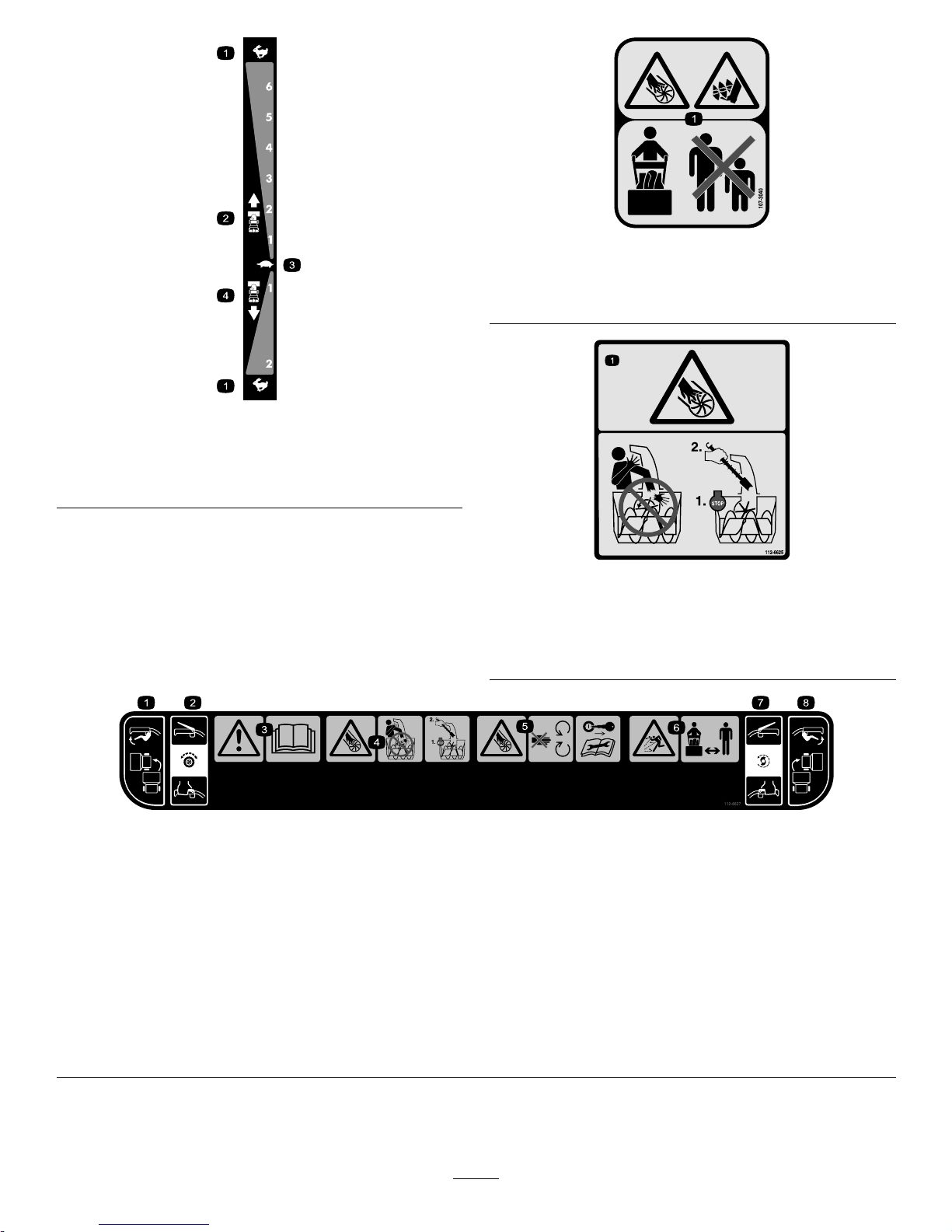
107-3040
1.Cuttingdismemberment,impellerandcutting
dismemberment,augerhazards—keepbystandersasafe
distancefromthemachine.
112-6625
Reorderpartno.112-6629
1.Cutting/dismembermenthazard,impeller—donotplace
yourhandinthechute;stoptheenginebeforeleavingthe
operator'sposition,usethetooltoclearthechute.
112-6627
1.Leftturncontrol
3.Warning—readthe
Operator'sManual.
5.Cutting/dismemberment
hazard,impeller—keep
awayfrommovingparts;
removetheignitionkeyand
readtheinstructionsbefore
servicingorperforming
maintenance.
7.Auger/impeller
drive—squeezetheleverto
engage;releasethelever
todisengage.
2.Tractiondrive—squeeze
thelevertoengage;release
thelevertodisengage.
4.Cutting/dismemberment
hazard,impeller—do
notplaceyourhand
inthechute;stopthe
enginebeforeleavingthe
operator'sposition,usethe
tooltoclearthechute.
6.Thrownobject
hazard—keepbystanders
asafedistancefromthe
machine.
8.Rightturncontrol
5
Page 6
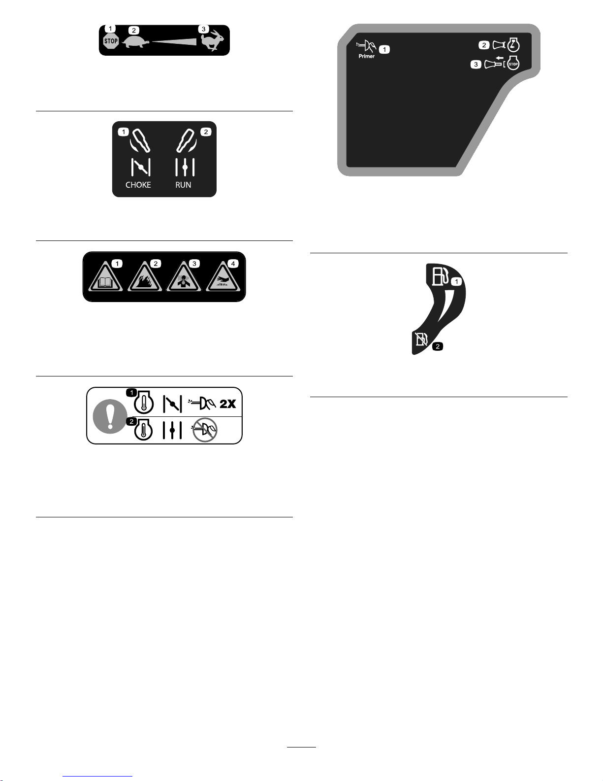
Briggs&StrattonPartNo.273676
1.Stop
3.Fast
2.Slow
Briggs&StrattonPartNo.275949
1.Chokeon(Choke)2.Chokeoff(Run)
Briggs&StrattonPartNo.276925
1.Warning—readthe
Operator'sManual.
3.Warning—toxicgas
inhalationhazard.
2.Warning—rehazard.
4.Warning—hot
surface/burnhazard.
Briggs&StrattonPartNo.277566
1.Whenstartingacold
engine,closethechoke
andpresstheprimertwo
times.
2.Whenstartingawarm
engine,openthechoke
anddonotpressthe
primer.
Briggs&StrattonPartNo.277588
1.Primer3.Ignitionkeyout
(Engine—Stop)
2.Ignitionkeyin
(Engine—Run)
Briggs&StrattonPartNo.278866
1.Fuel—On2.Fuel—Off
6
Page 7
Setup
LooseParts
Usethechartbelowtoverifythatallpartshavebeenshipped.
ProcedureDescription
Qty.
Use
Handlebolts4
Curvedwashers
4
1
Locknuts4
Installtheupperhandle.
2
Nopartsrequired
–
Installthewheelclutchcableends
3
Nopartsrequired
–
Installthetractioncontrollinkage.
Carriagebolts
2
4
Locknuts2
Installthechutecontrolrod.
5
Cabletie
1
Connectthewiretotheheadlight.
6
Nopartsrequired
–
Filltheenginewithoil.
7
Nopartsrequired
–
Checkthetirepressure.
8
Nopartsrequired
–
Checktheskids.
9
Nopartsrequired
–
Checktheoperationofthetractiondrive.
1
InstallingtheUpperHandle
Partsneededforthisprocedure:
4Handlebolts
4
Curvedwashers
4Locknuts
Procedure
Note:Donotremovetherubberbandonthecablesuntil
youhaveinstalledtheupperhandle.
1.Liftandrotatetheupperhandleandpositionitover
thelowerhandle(
Figure3).
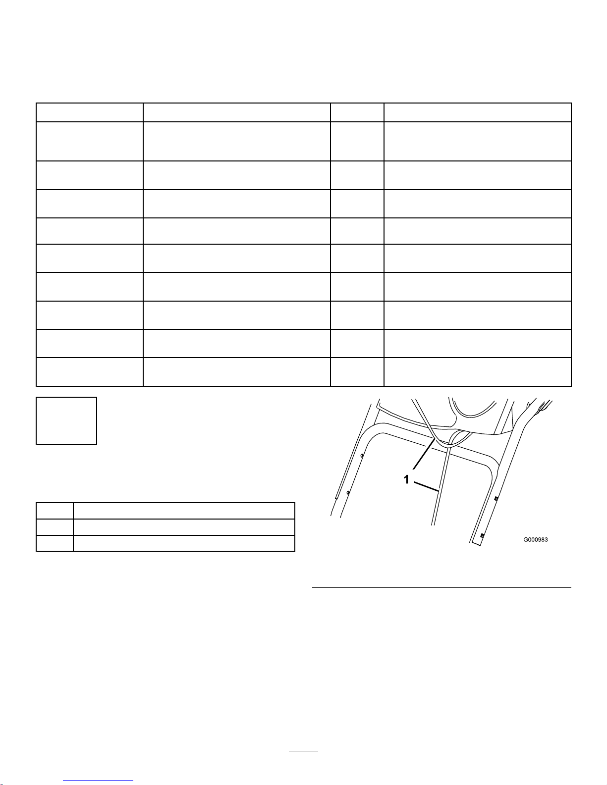
Important:Routethecablesattachedtothe
QuickStickinsidetheupperhandlelegsand
ensurethatthecablesandthewireforthe
headlightarenotpinchedbetweenthehandle
sections.
Figure3
1.Cables
2.Securetheupperhandlewith4handlebolts,4curved
washers,and4locknutsfromtheloosepartsbag
(Figure4).
7
Page 8
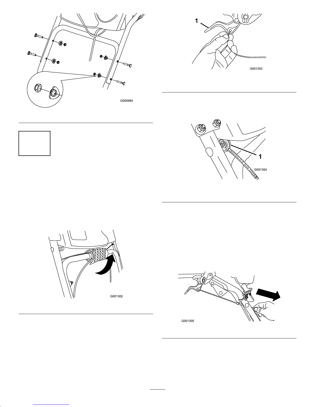
Figure4
2
InstallingtheWheelClutch
CableEnds
NoPartsRequired
Procedure
1.Unwrapthecableendsfromthelowerhandle
(Figure5).
Figure5
2.Routeeithertheleftorrightcableendoverthelower
handleandinsertthecableendintotheholeinthe
correspondingwheelclutchlever(Figure6).
Figure6
1.Wheelclutchlever
3.Removethenutandwasherfromthehandle,attach
thecableclamponthecabletothehandle,installthe
washerandthenut,andhandtightenthenut(Figure7).
Figure7
1.Cableclamp(2)
Important:Ensurethatthecurvedsideofthe
cableclampisagainstthehandleandthatthe
cableisroutedbelowtheclampbolt.Thecable
mustbeinastraightlinefromthecableclamp
tothepointwhereitattachestothewheelclutch
lever.
4.Pullthecablejacketdowngentlyuntilthewheelclutch
leverisdownandtheslackisoutofthecable,then
tightenthecableclampnutsecurely(Figure8).
Figure8
5.Squeezetheleverfully,thencheckthegapbetween
thebottomofthehandleandthewheelclutchlever
end(Figure9).
8
Page 9
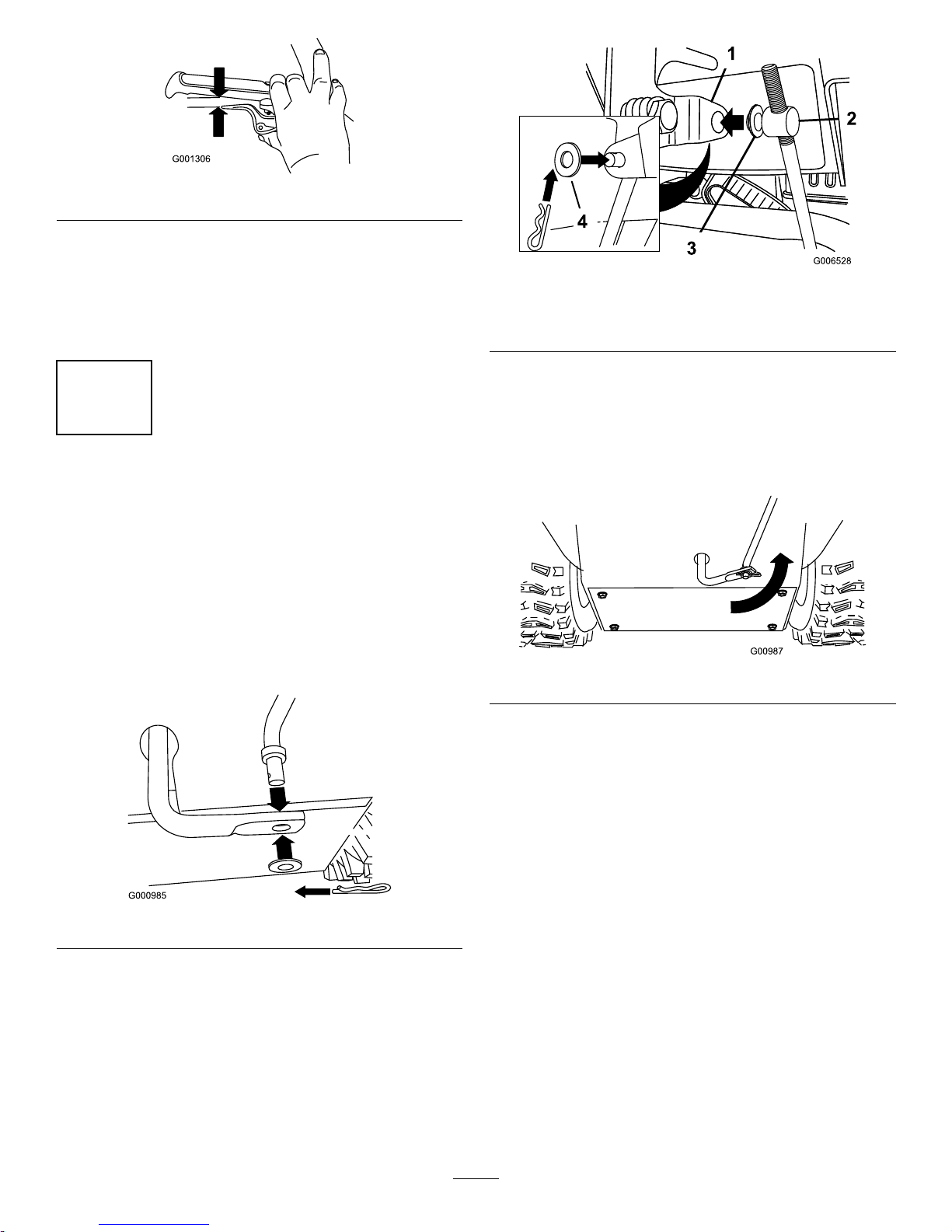
Figure9
Note:Thegapshouldbeapproximatelythethickness
ofapencil(1/4inchor6mm).Ifitisgreater,loosen
thecableclampnut,slidethecablejacketupslightly ,
tightenthecableclampnut,andcheckthegapagain.
6.Repeatsteps2through5fortheothercable.
3
InstallingtheTractionControl
Linkage
NoPartsRequired
Procedure
1.Removethehairpincotterandwasherfromthelower
endofthespeedcontrolrodandinsertthelowerend
oftherodintothelowerlinkarmsothatthebentend
ofthespeedcontrolrodfacesrearward(Figure10).
Figure10
2.Securethelowerendofthespeedcontrolrodwiththe
washerandhairpincotterthatyoupreviouslyremoved.
3.Removethehairpincotterandtheouterwasherfrom
thetrunnionontheupperendofthespeedcontrol
rod(Figure11).
Figure11
1.Speedselectorlever
3.Innerwasher
2.Trunnion
4.Outerwasher
Note:Tomakeinstallationeasier,leavetheatwasher
onthetrunnion(Figure11).
4.ShiftthespeedselectorleverintoPositionR2.
5.Rotatethelowerlinkarmfullyupward
(counterclockwise)(Figure12).
Figure12
6.Liftuponthespeedcontrolrodandinsertthetrunnion
intotheholeinthespeedselectorlever(Figure11).
Note:Ifthetrunniondoesnottintothehole
whenyouliftuponthespeedcontrolrod,rotatethe
trunnionupwardordownwardonthespeedcontrol
roduntilitts.
7.Securethetrunnionandupperendofthespeedcontrol
rodwiththeouterwasherandahairpincotteryou
previouslyremoved.
9
Page 10
Note:Foreasierinstallation,lookdownthroughthe
openinginthespeedselector(Figure13).
Figure13
1.Speedselector
4
InstallingtheChuteControl
Rod
Partsneededforthisprocedure:
2
Carriagebolts
2Locknuts
Procedure
1.UnwraptheQuickStickandrotateitsothatitis
uprightandinthecenter.
2.Holdthebluetriggercapdownandpulltheleverfully
rearward.
Note:Thedischargechuteanddeectorshouldface
forward.Iftheydonot,holdthebluetriggercap
down(butdonotmovetheQuickStick)androtatethe
dischargechuteuntiltheydo.
3.Aligntheattenedbackendofthelongchutecontrol
rodwiththeattenedfrontendoftheshortrod
thatextendsfromthecontrolpanelsothattheynest
together(Figure14).
g018656
Figure14
1.Shortrod
2.Longchutecontrolrod
4.Insertthefrontendoftherodintotheopeningin
thebackofthechutegearcoveruntilitslidesintothe
chutegear(Figure15).
Figure15
5.Aligntheholesinthenestedendsoftherodsand
insert2carriagebolts(intheloosepartsbag)through
theshortrodfromtheleftsideofthemachine(from
theoperatingposition).
6.Insertthecableclipthatsupportsthedeectorcable
undertheheadoftheforwardcarriagebolt,andsecure
thecarriageboltswithlocknutsfromthelooseparts
bag(Figure16).
g018657
Figure16
1.Cableclip2.Deectorcable
10
Page 11

7.HoldthebluetriggercapdownandrotatetheQuick
Stickinacircletoensurethatthechuteanddeector
operatesmoothly.
5
ConnectingtheWiretothe
Headlight
Partsneededforthisprocedure:
1
Cabletie
Procedure
1.Insertthewireconnectoronthelooseendofthewire
straightintothebackoftheheadlightuntilitissecurely
inplace(Figure17).
Figure17
1.Plasticcliponwire
connector
3.Cabletie
2.U-bolt
Note:Ensurethattheplasticcliponthewire
connectorisonthebottom(Figure17).
2.Secureacabletie(fromtheloosepartsbag)aroundthe
wireandthehandleaboutaninch(2.5cm)belowthe
U-bolt(Figure17).
6
FillingtheEnginewithOil
NoPartsRequired
Procedure
Yourmachinecomeswithoilintheenginecrankcase.
Note:Beforestartingtheengine,checktheoilleveland
addoilifnecessary.
UseautomotivedetergentoilwithanAPIserviceclassication
ofSF ,SG,SH,SJ,SL,orhigher.Refertoyourengineowner's
manual.
UseFigure18belowtoselectthebestoilviscosityforthe
outdoortemperaturerangeexpected:
Figure18
1.UsingSAE30atoutdoor
temperaturesbelow40°F
(4°C)willresultinhard
starting.
2.Using10W-30atoutdoor
temperaturesabove
80°F(27°C)mayresultin
increasedoilconsumption;
therefore,checktheoil
levelmorefrequentlyin
thesecircumstances.
EngineOilCapacity
Model
EngineOilCapacity
38828
26to28oz.(0.77to0.83l)
1.Removethedipstickandslowlypouroilintothe
oillltubetoraisetheoilleveltotheFullmarkon
thedipstick.Donotoverll(Figure19).Referto
CheckingtheEngineOilLevelinMaintenance.
11
Page 12

Figure19
2.Installthedipsticksecurely.
Note:Donotspilloilaroundtheoillltube;oilcould
leakontotractionpartsandcausethetractiontoslip.
7
CheckingtheTirePressure
NoPartsRequired
Procedure
Thetiresareoverinatedatthefactoryforshipping.Reduce
thepressureequallyinbothtirestobetween17and20psi
(116and137kPa).
8
CheckingtheSkids
NoPartsRequired
Procedure
RefertoCheckingandAdjustingtheSkidsinMaintenance.
9
CheckingtheTractionDrive
Operation
NoPartsRequired
Procedure
CAUTION
Ifthetractiondriveisnotproperlyadjusted,the
machinemaymoveinthedirectionoppositeof
whatyouintended,causinginjuryand/orproperty
damage.
Carefullycheckthetractiondriveandadjustit
properly,ifnecessary .
1.Starttheengine;refertoStartingtheEngine.
2.MovethespeedselectortoPositionR1;referto
OperatingtheSpeedSelector.
3.Squeezethelefthand(traction)levertothehand-grip
(
Figure20).
Figure20
Themachineshouldmoverearward.Ifthemachine
doesnotmoveormovesforward,completethe
following:
A.Releasethetractionleverandstoptheengine.
B.Disconnectthetrunnionfromthespeedselector
lever(Figure11).
C.Turnthetrunniondownward(clockwise)onthe
speedcontrolrod(Figure11).
D.Connectthetrunniontothespeedselectorlever
(Figure11).
4.Releasethetractionlever.
5.MovethespeedselectortothePosition1;referto
OperatingtheSpeedSelector.
6.Squeezethelefthand(traction)levertothehand-grip
(Figure20).
12
Page 13

Themachineshouldmoveforward.Ifthemachine
doesnotmoveormovesrearward,completethe
following:
A.Releasethetractionleverandstoptheengine.
B.Disconnectthetrunnionfromthespeedselector
lever(Figure11).
C.Turnthetrunnionupward(counterclockwise)on
thespeedcontrolrod(
Figure11).
D.Connectthetrunniontothespeedselectorlever
(Figure11).
7.Ifyoumadeanyadjustments,repeatthisprocedure
untilnoadjustmentsarerequired.
Important:Ifthemachinemoveswhenthetraction
leverisinthereleasedposition,checkthetractioncable
(refertoCheckingandAdjustingtheTractionCable)or
takethemachinetoanAuthorizedServiceDealerfor
service.
ProductOverview
Figure21
1.Hand-grip(2)10.Scraper
2.Auger/impellerlever
11.Auger
3.Speedselectorlever12.Skid(2)
4.QuickStick™discharge
chutecontrol
13.Electricstarterbutton
5.Tractionlever14.Electricstarterplug
6.Fueltankcap
15.Snowcleanouttool
7.Engineoillltube/dipstick
16.Headlight
8.Chutedeector17.Wheelclutchlever(2)
9.Dischargechute
Figure22
1.Choke
5.Recoilstarter
2.Ignitionswitch
6.Oildrainplug
3.Fuelshutoffvalve
7.Primer
4.Throttle
13
Page 14

Figure23
1.Snowcleanouttool(attachedtothehandle)
Operation
Note:Determinetheleftandrightsidesofthemachine
fromthenormaloperatingposition.
FillingtheFuelTank
DANGER
Gasolineisextremelyammableandexplosive.A
reorexplosionfromgasolinecanburnyouand
others.
•Topreventastaticchargefromignitingthe
gasoline,placethecontainerand/ormachine
onthegroundbeforelling,notinavehicleor
onanobject.
•Fillthetankoutdoorswhentheengineiscold.
Wipeupspills.
•Donothandlegasolinewhensmokingoraround
anopenameorsparks.
•Storegasolineinanapprovedfuelcontainer,out
ofthereachofchildren.
•Forbestresults,useonlyclean,fresh,unleadedgasoline
withanoctaneratingof87orhigher((R+M)/2rating
method).
•Oxygenatedfuelwithupto10%ethanolor15%MTBE
byvolumeisacceptable.
•DoNotuseethanolblendsofgasoline(suchasE15
orE85)withmorethan10%ethanolbyvolume.
Performanceproblemsand/orenginedamagemayresult
whichmaynotbecoveredunderwarranty.
•DoNotusegasolinecontainingmethanol.
•DoNotstorefueleitherinthefueltankorfuelcontainers
overthewinterunlessafuelstabilizerisused.
•DoNotaddoiltogasoline.
Important:T oreducestartingproblems,addfuel
stabilizertothefuelallseason,mixingitwithgasoline
lessthan30daysold.
Do not add oil to the gasoline.
Figure24
1.1-1/2inch(3.8cm)
StartingtheEngine
1.Checktheengineoillevel.RefertoCheckingthe
EngineOilLevelinMaintenance.
2.Turnthefuelshutoffvalve1/4turncounterclockwise
toopenit(Figure25).
Figure25
3.Inserttheignitionkey(Figure26).
14
Page 15

Figure26
1.Ignitionkey
4.Firmlypushintheprimerwithyourthumb2times
(15°For-9°Corabove)or4times(below15°For
-9°C),holdingtheprimerinforasecondbefore
releasingiteachtime(Figure27).
Figure27
5.RotatethechoketotheChokeposition(Figure28).
Figure28
6.MovethethrottletotheFastposition(Figure29).
Figure29
7.Startthemachinepullingtherecoilstarterorpressing
theelectric-starterbutton(
Figure30).
Figure30
1.Electric-starterbutton3.Recoilstarter
2.Electricstarterplug
Note:Tousetheelectricstarter,connectapower
cordtotheelectricstarterplugrstandthentoa
poweroutlet.
Important:Topreventdamagingtheelectric
starter,runitinshortcycles(5secondsmaximum,
thenwaitoneminutebeforetryingtostartit
15
Page 16

again).Iftheenginestilldoesnotstart,take
themachinetoanAuthorizedServiceDealerfor
service.
8.Disconnectthepowercordfromthepoweroutletrst
andthenfromthemachine.
9.Allowtheenginetowarmupforseveralminutes,move
thechoketowardtheRunposition.Waitfortheengine
torunsmoothlybeforeeachchokeadjustment.
CAUTION
Ifyouleavethemachinepluggedintoa
poweroutlet,someonecaninadvertentlystart
themachineandinjurepeopleordamage
property.
Unplugthepowercordwheneveryouarenot
startingthemachine.
StoppingtheEngine
1.MovethethrottletotheSlowposition,andthentothe
Stopposition(Figure31).
Figure31
2.Waitforallmovingpartstostopbeforeleavingthe
operatingposition.
3.Removetheignitionkey.
4.Closethefuelshutoffvalvebyrotatingitclockwise
(Figure32).
Figure32
5.Pulltherecoilstarter3or4times.Thishelpsprevent
therecoilstarterfromfreezingup.
OperatingtheTractionDrive
CAUTION
Ifthetractiondriveisnotproperlyadjusted,the
machinemaymoveinthedirectionoppositeof
whatyouintended,causinginjuryand/orproperty
damage.
Carefullycheckthetractiondriveandadjustit
properly,ifnecessary;refertoCheckingtheTraction
DriveOperationinSetupformoreinformation.
Important:Ifthemachinemoveswhenthetraction
leverisinthereleasedposition,checkthetractioncable
(refertoCheckingandAdjustingtheTractionCable)or
takethemachinetoanAuthorizedServiceDealerfor
service.
1.Toengagethetractiondrive,squeezethelefthand
(traction)levertothehand-grip(
Figure33).
Figure33
2.Tostopthetractiondrive,releasethetractionlever.
16
Page 17

UsingtheWheelClutchLevers
Thewheelclutchleversallowyoutomomentarilydisengage
thedrivetooneorbothwheelswiththetractiondrivelever
stillengaged.Thisenablesyoutoturnandmaneuverthe
machineeasily.
Note:Holdingdownthetractionleveragainstthehandle
engagesthetractiondrivetobothwheels.
Toturnthemachinetotheright,liftupontherightwheel
clutchleverandsqueezeittowardthehandle(Figure34).
Figure34
Note:Thisdisengagesthedrivetotherightwheelwhile
theleftwheelcontinuesdriving,andthemachineturnsto
theright.
Note:Similarly ,squeezingtheleftwheelclutchleverturns
themachinetotheleft.
Whenyoucompletetheturn,releasethewheelclutchlever,
andthedrivere-engagesbothwheels(Figure35).
Figure35
Momentarilysqueezingandreleasingtheleftorrightwheel
clutchleveralsoallowsforsteeringadjustmentstokeepthe
machinegoinginastraightline,especiallyindeepsnow .
Squeezingbothwheelclutchleverssimultaneouslydisengages
thedrivetobothwheels.Thisenablesyoutomanuallymove
themachinebackwardwithoutstoppingtoshiftitintoa
reversegear.Italsoallowsyoutomaneuverandtransportthe
machinemoreeasilywhentheengineisnotrunning.
OperatingtheSpeedSelector
Thespeedselectorhas6forwardand2reversegears.T o
changespeeds,releasethetractionleverandshiftthespeed
selectorlevertothedesiredposition(Figure36).Thelever
locksinanotchateachspeedselection.
Figure36
OperatingtheAuger/Impeller
Drive
1.Toengagetheauger/impellerdrive,squeezethe
righthand(auger/impeller)levertothehandgrip
(
Figure37).
Figure37
2.Tostoptheaugerandimpeller,releasetherighthand
lever.
Important:Whenyouengageboththe
auger/impellerleverandthetractionlever,the
tractionleverlockstheauger/impellerleverdown,
freeingyourrighthand.T oreleasebothlevers,
simplyreleasethelefthand(traction)lever.
3.Iftheaugerandimpellercontinuetorotatewhenyou
releasetheauger/impellerlever,donotoperatethe
machine.Checktheauger/impellercable(referto
CheckingandAdjustingtheAuger/ImpellerCable)
andadjustitifnecessary.Otherwise,takethemachine
toanAuthorizedDealerforservice.
WARNING
Iftheaugerandimpellercontinuetorotate
whenyoureleasetheauger/impellerlever,you
couldseriouslyinjureyourselforothers.
Donotoperatethemachine.Takeittoan
AuthorizedServiceDealerforservice.
OperatingtheQuickStick
®
HoldthebluetriggercapdowntousetheQuickStickto
movethedischargechuteandthechutedeector.Releasethe
17
Page 18

triggercaptolockthedischargechuteandchutedeector
intoposition(Figure38).
Figure38
MovingtheDischargeChute
HoldthebluetriggercapdownandmovetheQuickStick
tothelefttomovethedischargechutetotheleft;movethe
QuickSticktotherighttomovethedischargechutetothe
right(Figure39).
Figure39
•Ifthechutedoesnotmove,refertoAdjustingthe
DischargeChuteLatch.
•Ifthechutedoesnotturnasfartotheleftasitdoesto
theright,ensurethatthecableisroutedtotheinsideof
thehandles.RefertoInstallingtheUpperHandle.
•Ifthechutedoesnotlockintoplacewhenyoureleasethe
triggercap,refertoAdjustingtheDischargeChuteLatch.
MovingtheChuteDeector
HoldthebluetriggercapdownandmovetheQuickStick
forwardtolowerthechutedeector;moveitrearwardtoraise
thechutedeector(
Figure40).
Figure40
UncloggingtheDischarge
Chute
Iftheauger/impellerisrunningbutthereisnosnowcoming
outofthedischargechute,thedischargechutemaybe
clogged.
•Tounclogthedischargechute,stayintheoperating
positionandreleasethelefthand(traction)lever.While
runningtheauger/impeller,pushdownonthehandlesto
raisethefrontofthemachineafewinches(centimeters)
offthepavement.Thenliftthehandlesquicklytobump
thefrontofthemachineonthepavement.Repeatif
necessaryuntilastreamofsnowcomesoutthedischarge
chute.
•Ifyoucannotunclogthedischargechutebybumping
thefrontofthemachine,stoptheengine,waitforall
movingpartstostop,andusethesnowclean-out
toolorastick;neveruseyourhand.
Important:Uncloggingthedischargechuteby
bumpingthefrontofthemachineonthepavement
maycausetheskidstomove.Adjusttheskidsand
tightentheskidboltssecurely.
PreventingFreeze-up
•Insnowyandcoldconditions,somecontrolsandmoving
partsmayfreeze.Donotuseexcessiveforcewhen
tryingtooperatefrozencontrols.Ifyouhavedifculty
operatinganycontrolorpart,starttheengineandletit
runforafewminutes.
•Afterusingthemachine,lettheenginerunforafew
minutestopreventmovingpartsfromfreezing.Engage
theauger/impellertoclearanyremainingsnowfrom
insidethehousing.RotatetheQuickSticktopreventit
fromfreezing.Stoptheengine,waitforallmovingparts
tostop,andremovealliceandsnowfromthemachine.
•Withtheengineoff,pulltherecoilstarterhandleseveral
timesandpushtheelectric-starterbuttononcetoprevent
therecoilandelectricstartersfromfreezingup.
18
Page 19

OperatingTips
DANGER
Whenthemachineisinoperation,theimpellerand
augercanrotateandcutofforinjurehandsandfeet.
•Beforeadjusting,cleaning,inspecting,
troubleshooting,orrepairingthemachine,stop
theengineandwaitforallmovingpartstostop.
Disconnectthewirefromthesparkplugand
keepitawayfromtheplugtopreventsomeone
fromaccidentallystartingtheengine.
•Removeanobstructionfromthedischarge
chute;refertoUncloggingtheDischargeChute.
Ifnecessary ,usethesnowclean-outtoolora
stick,notyourhands,toremoveanobstruction
fromthedischargechute.
•Staybehindthehandlesandawayfromthe
dischargeopeningwhileoperatingthemachine.
•Keepface,hands,feet,andanyotherpartof
yourbodyorclothingawayfromconcealed,
moving,orrotatingparts.
WARNING
Therotorbladescanthrowstones,toys,andother
foreignobjectsandcauseseriouspersonalinjuryto
theoperatorortobystanders.
•Keeptheareatobeclearedfreeofallobjects
thattherotorbladescouldpickupandthrow.
•Keepallchildrenandpetsawayfromthearea
ofoperation.
•AlwayssetthethrottletotheFastpositionwhenthrowing
snow .
•Iftheengineslowsdownunderaloadorthewheelsslip,
shiftthemachineintoalowergear.
•Ifthefrontofthemachineridesup,shiftthemachine
intoalowergear.Ifthefrontcontinuestorideup,liftup
onthehandles.
•Thepivotingscraperonthemachineisnot
recommendedforuseongravelsurfaces.Butifyou
mustusethemachineonagravelsurface,adjustthe
skidsfurtherdowntopreventthepivotingscraperfrom
pickinguprocks.
19
Page 20

Maintenance
Note:Determinetheleftandrightsidesofthemachinefromthenormaloperatingposition.
RecommendedMaintenanceSchedule(s)
MaintenanceService
Interval
MaintenanceProcedure
Aftertherst2hours
•Inspectthetractioncableandadjustitifnecessary.
Aftertherst5hours
•Changetheengineoil.
Beforeeachuseordaily
•Checktheengineoillevelandaddoilifnecessary.
Every50hours
•Changetheengineoil.Changetheengineoilevery25operatinghourswhen
operatingtheengineunderaheavyload.
Yearly
•Checktheskidsandadjustthemifnecessary.
•Inspectthetractioncableandadjustorreplaceitifnecessary.
•Checktheaugergearboxoilandaddoilifnecessary .
Yearlyorbeforestorage
•Checktheairpressureinthetiresandinatethemto17–20psi(116–137kPa).
•Drainthegasolineandruntheenginetodryoutthefueltankandthecarburetorat
theendoftheseason.
•HaveanAuthorizedServiceDealerinspectandreplacethetractiondrivebeltand/or
theauger/impellerdrivebelt,ifnecessary.
Important:Youcanndmoreinformationaboutmaintainingandservicingyourmachineatwww .T oro.com.
Important:Refertoyourengineoperator'smanualforadditionalmaintenanceprocedures.Forengineadjustments,
repairs,orwarrantyservicenotcoveredinthismanual,contactanAuthorizedBriggs&StrattonServicingDealer.
20
Page 21

PreparingforMaintenance
1.Movethemachinetoalevelsurface.
2.Stoptheengineandwaitforallmovingpartstostop.
3.Disconnectthesparkplugwire.RefertoReplacing
theSparkPlug.
CheckingtheEngineOilLevel
ServiceInterval:Beforeeachuseordaily—Checktheengine
oillevelandaddoilifnecessary.
1.Removethedipstick,wipeitclean,thenfullyinstall
thedipstick.
2.Removethedipstickandchecktheoillevel(
Figure41).
IftheoillevelisbelowtheAddmarkonthedipstick,
addoil.RefertoFillingtheEnginewithOil.
Figure41
CheckingandAdjustingthe
Skids
ServiceInterval:Yearly—Checktheskidsandadjustthem
ifnecessary.
Checktheskidstoensurethattheaugerdoesnotcontact
thepavedorgravelsurface.Adjusttheskidsasneededto
compensateforwear.
1.Checkthetirepressure.RefertoCheckingtheTire
Pressure.
2.Movethemachinetoalevelsurface.
3.Loosenthenutsthatsecurebothskidstotheauger
sidesuntiltheskidsslideupanddowneasily(
Figure42).
Figure42
1.Skid
4.Pushdownonthehandlestoallowthepivoting
scrapertomovefullyforward,thensetthefrontofthe
machinedownsothatthefrontedgeofthepivoting
scrapercontactstheground(
Figure43).
Figure43
1.Pivotingscraper
5.Movetheskidsdownuntiltheyareevenwiththe
ground.
Note:Forasmoothsurface,youcansettheskids
slightlyhighertoincreasethescrapingaction,butset
theskidsfarenoughdowntopreventtheaugerblades
fromcontactingtheground.
Note:Thepivotingscraperonthemachineisnot
recommendedforuseongravelsurfaces.Butif
youmustusethemachineonagravelsurface,adjust
theskidsfurtherdowntopreventthepivotingscraper
frompickinguprocks.
6.Firmlytightenthenutsthatsecurebothskidstothe
augersides.
Note:Iftheskidsbecomeexcessivelyworn,youcan
turnthemoverandsettheunusedsidetowardthe
pavement.
CheckingandAdjustingthe
TractionCable
ServiceInterval:Aftertherst2hours—Inspectthe
tractioncableandadjustitifnecessary.
Yearly—Inspectthetractioncableand
adjustorreplaceitifnecessary.
21
Page 22

Ifthemachinedoesnotdriveintheforwardorreversespeeds
oritdriveswhenyoureleasethetractionlever,adjustthe
tractioncable.
Withthetractionleverdisengaged,checkthepininthe
elongatedslotintheleftsideofthemachineabovethe
tire.Thereshouldbeagapof1/32to1/16inch(1to1.5
mm)fromthefrontoftheslottothefrontedgeofthepin
(Figure44).
Figure44
1.Pin
Ifthelefthand(traction)cableisnotproperlyadjusted,do
thefollowingsteps:
1.Loosenthejamnut.
2.Loosenortightentheturnbuckletoadjustthepinuntil
itisthepropergapfromthefrontedgeoftheslot.
3.Tightenthejamnut(Figure45).
Figure45
1.Jamnut2.Turnbuckle
CheckingtheAugerGearbox
OilLevel
ServiceInterval:Yearly—Checktheaugergearboxoiland
addoilifnecessary.
1.Movethemachinetoalevelsurface.
2.Cleantheareaaroundthepipeplug(
Figure46).
Figure46
3.Removethepipeplugfromthegearbox.
4.Checktheoillevelinthegearbox.Theoilshouldbeat
thepointofoverowingatthelleropening.
5.Iftheoillevelislow ,addGL-5orGL-6,SAE85-95
EPtransmissionoiltothegearboxuntilthepointof
overow .
Note:Donotusesyntheticoil.
6.Installthepipepluginthegearbox.
ChangingtheEngineOil
ServiceInterval:Aftertherst5hours—Changetheengine
oil.
Every50hours—Changetheengineoil.
Changetheengineoilevery25operating
hourswhenoperatingtheengineundera
heavyload.
Ifpossible,runtheenginejustbeforechangingtheoilbecause
warmoilowsbetterandcarriesmorecontaminants.
UseautomotivedetergentoilwithanAPIserviceclassication
ofSF ,SG,SH,SJ,SL,orhigher.Refertoyourengineowner's
manual.
UseFigure47belowtoselectthebestoilviscosityforthe
outdoortemperaturerangeexpected:
22
Page 23

Figure47
1.UsingSAE30atoutdoor
temperaturesbelow40°F
(4°C)willresultinhard
starting.
2.Using10W-30atoutdoor
temperaturesabove
80°F(27°C)mayresultin
increasedoilconsumption;
therefore,checktheoil
levelmorefrequentlyin
thesecircumstances.
EngineOilCapacity
Model
EngineOilCapacity
38828
26to28oz.(0.77to0.83l)
1.Cleantheareaaroundtheoildraincap(Figure48).
Figure48
1.Oildraincap
2.Slideanoildrainpanunderthedrainextensionand
removetheoildraincap.
3.Draintheoil.
Note:Disposeoftheusedoilproperlyatalocal
recyclingcenter.
4.Installtheoildraincap.
5.Fillthecrankcasewithoil.RefertoFillingtheEngine
CrankcasewithOil.
AdjustingtheDischargeChute
Latch
Ifthedischargechutedoesnotlockintothedesiredposition
ordoesnotunlocksothatyoucanmoveittoanother
position,adjustthedischargechutelatch.
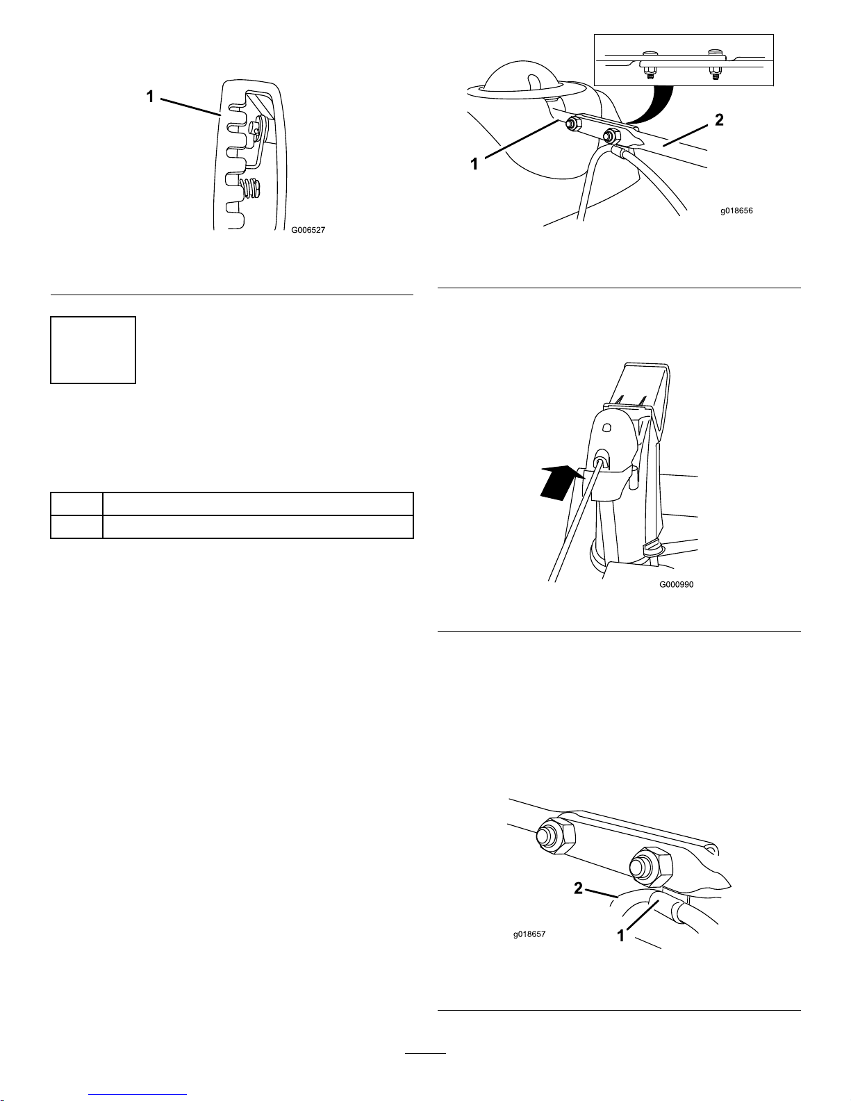
1.Removethefasteneronthegearcover(
Figure49),lift
thefrontofthecoverup,andslideitbackandoutof
theway.
Figure49
2.Loosentheboltonthecableclamp(Figure50).
Figure50
1.Cableconduit2.Cableclamp
3.Graspthecableconduitandmoveittowardthefront
ofthemachineuntilthedischargechutelatchfully
engagesthegearteeth(
Figure50andFigure51).
Figure51
1.Dischargechutelatch
2.Gearteeth
23
Page 24

Note:Thelatchisspringloadedandwillnaturally
moveintotheteethofthegear(Figure51).
4.Removeanyslackinthecablebypullingthecable
conduitrearward.
5.Tightentheboltonthecableclamp.
6.Installandsecurethegearcover.
ReplacingtheDriveBelts
Iftheauger/impellerdrivebeltorthetractiondrivebelt
becomesworn,oil-soaked,orotherwisedamaged,goto
www.Toro.comforadditionalserviceinformationorhavean
AuthorizedServiceDealerreplacethebelt.
ReplacingtheHeadlightBulb
UseaGE89216Whalogenlightbulb.Donottouchthe
bulbwithyourhandsorallowdirtormoisturetocomeinto
contactwiththebulb.
1.Removethewireconnectorfromthebackofthe
headlight(Figure52).
Figure52
2.Turnthebaseofthebulbcounterclockwiseuntilit
stops(Figure53).
Figure53
3.Removethebulbstraightoutfromthebackofthe
headlight(Figure54).
Figure54
4.Insertanewbulbintothebackoftheheadlight
(Figure55).
Figure55
5.Turnthebaseofthebulbclockwiseuntilitissnug
(Figure56).
Figure56
6.Insertthewireconnectorstraightintothebackofthe
headlightuntilitissecurelyinplace(Figure57).
Figure57
24
Page 25

Storage
WARNING
•Gasolinevaporscanexplode.
•Donotstoregasolinemorethan30days.
•Donotstorethemachineinanenclosurenear
anopename.
•Allowtheenginetocoolbeforestoringit.
PreparingtheMachinefor
Storage
1.Onthelastrefuelingoftheyear,addfuelstabilizerto
freshfuelasdirectedbytheenginemanufacturer.
2.Runtheenginefor10minutestodistributethe
conditionedfuelthroughthefuelsystem.
3.Loosenthehoseclampthatsecuresthefuellinetothe
valveandslidethefuellineoffthefuelshutoffvalve.
4.Openthefuelshutoffvalveandallowthefueltodrain
outofthefueltankintoanapprovedfuelcontainer.
5.Installthefuellineontothefuelshutoffvalveand
secureitwithahoseclamp.
6.Runthemachineuntiltheenginestopsfromrunning
outoffuel.
7.Primetheengineandstartitagain.
8.Allowtheenginetorununtilitstops.Whenyoucan
nolongerstarttheengine,itissufcientlydry.
9.Stoptheengineandallowittocool.
10.Removetheignitionkey.
11.Disconnectthesparkplugwire.
12.Removethesparkplug,add1oz.(30ml)ofoilthrough
thesparkplughole,andpullthestarterropeslowly
severaltimestodistributeoilthroughoutthecylinder
topreventcylindercorrosionduringtheoff-season.
13.Looselyinstallthesparkplug.
14.Disposeofanyunusedfuelproperly.Recycleit
accordingtolocalcodes,oruseitinyourautomobile.
Note:Donotstorestabilizedfuelformorethan
90days.
15.Cleanthemachinethoroughly.
16.Touchupchippedsurfaceswithpaintavailablefroman
AuthorizedServiceDealer.Sandaffectedareasbefore
painting,andusearustpreventativetopreventthe
metalpartsfromrusting.
17.Tightenallloosescrews,bolts,andlocknuts.Repairor
replaceanydamagedparts.
18.Coverthemachineandstoreitinaclean,dryplace
outofthereachofchildren.Allowtheenginetocool
beforestoringitinanyenclosure.
RemovingtheMachinefrom
Storage
1.Removethesparkplugandspintheenginerapidly
usingthestartertoblowtheexcessoilfromthe
cylinder.
2.Installthesparkplugbyhandandthentorqueitto
15ft-lb(20.4N-m).
3.Connectthesparkplugwire.
4.Performtheannualmaintenanceproceduresasgiven
intheRecommendedMaintenanceSchedule.
25
Page 26

Troubleshooting
Problem
PossibleCauseCorrectiveAction
1.Thepowercordisdisconnectedatthe
outletorthemachine.
1.Connectthepowercordtotheoutlet
and/orthemachine.
2.Thepowercordisworn,corroded,or
damaged.
2.Replacethepowercord.
Electricstarterdoesnotturn(electric-start
modelsonly)
3.Thepoweroutletisnotenergized.
3.Haveaqualiedelectricianenergize
theoutlet.
1.Thekeyisnotintheignitionorisinthe
Stopposition.
1.Insertthekeyintotheignitionandturn
ittotheOnposition.
2.ThechokeisintheOffpositionandthe
primerhasnotbeenpressed.
2.MovethechoketotheOnpositionand
presstheprimer3times.
3.Thefuelshutoffvalveisnotopen.3.Openthefuelshutoffvalve.
4.ThethrottleisnotintheFastposition.4.MovethethrottletotheFastposition.
5.Thefueltankisemptyorthefuel
systemcontainsstalefuel.
5.Drainand/orllthefueltankwithfresh
gasoline(notmorethan30daysold).
Iftheproblempersists,contactan
AuthorizedServiceDealer.
6.Thesparkplugwireislooseor
disconnected.
6.Connectthewiretothesparkplug.
7.Thesparkplugispitted,fouled,orthe
gapisincorrect.
7.Checkthesparkplugandadjustthe
gapifnecessary .Replacethespark
plugifitispitted,fouled,orcracked.
8.Thefuelventcapisrestricted.
8.Removetheventrestrictionorreplace
thefuelcap.
Enginedoesnotstartorstartshard
9.Theengineoillevelintheengine
crankcaseistoolowortoohigh.
9.Addordrainoiltoadjusttheoillevelin
theenginecrankcasetotheFullmark
onthedipstick.
1.ThechokeisintheOnposition.1.MovethechoketotheOffposition.
2.Thefuelshutoffvalveisnotcompletely
open.
2.Openthefuelshutoffvalve.
3.Thefueltankisnearlyemptyor
containsstalefuel.
3.Drainandllthefueltankwithfresh
gasoline(notmorethan30daysold).
Iftheproblempersists,contactan
AuthorizedServiceDealer.
4.Thesparkplugwireisloose.
4.Connectthewiretothesparkplug.
5.Thesparkplugispitted,fouled,orthe
gapisincorrect.
5.Checkthesparkplugandadjustthe
gapifnecessary .Replacethespark
plugifitispitted,fouled,orcracked.
Enginerunsrough
6.Theengineoillevelintheengine
crankcaseistoolowortoohigh.
6.Addordrainoiltoadjusttheoillevelin
theenginecrankcasetotheFullmark
onthedipstick.
26
Page 27

Problem
PossibleCauseCorrectiveAction
1.ThethrottleisnotintheFastposition
whenthrowingsnow .
1.MovethethrottletotheFastposition.
2.Themachineismovingtoofasttoclear
thesnow.
2.Shiftthemachineintoalowergear.
3.Youaretryingtoremovetoomuch
snowperswath.
3.Reducetheamountofsnowremoved
perswath.
4.Youaretryingtoremoveextremely
heavyorwetsnow.
4.Don'toverloadthemachinewith
extremelyheavyorwetsnow.
5.Thedischargechuteisplugged.5.Unclogthedischargechute.
6.Theauger/impellerdrivebeltisloose
orisoffthepulley.
6.Installand/oradjusttheauger/impeller
drivebelt;refertowww.Toro.com
forservicinginformationortakethe
machinetoanAuthorizedService
Dealer.
Engineruns,butthemachinedischarges
snowpoorlyornotatall
7.Theauger/impellerdrivebeltisworn
orbroken.
7.Replacetheauger/impellerdrivebelt;
refertowww.Toro.comforservicing
informationortakethemachinetoan
AuthorizedServiceDealer.
Dischargechuteeitherdoesnotlockinto
placeordoesnotmove
1.Thedischargechutelatchisnot
properlyadjusted.
1.Adjustthedischargechutelatch.
1.Theskidsand/orscraperarenot
properlyadjusted.
1.Adjusttheskidsand/orthescraper.
Themachinedoesnotproperlyclearthe
snowoffthesurface
2.Thepressureinthetiresisnotequal.
2.Checkandadjustthepressureinone
orbothtires.
27
Page 28

Notes:
28
Page 29

Notes:
29
Page 30

EuropeanPrivacyNotice
TheInformationT oroCollects
ToroWarrantyCompany(T oro)respectsyourprivacy.Inordertoprocessyourwarrantyclaimandcontactyouintheeventofaproductrecall,weaskyou
tosharecertainpersonalinformationwithus,eitherdirectlyorthroughyourlocalT orodealer.
TheTorowarrantysystemishostedonserverslocatedwithintheUnitedStateswhereprivacylawmaynotprovidethesameprotectionasapplies
inyourcountry.
BYSHARINGYOURPERSONALINFORMA TIONWITHUS,YOUARECONSENTINGTOTHEPROCESSINGOFYOURPERSONALINFORMATION
ASDESCRIBEDINTHISPRIV ACYNOTICE.
TheW ayT oroUsesInformation
Toromayuseyourpersonalinformationtoprocesswarrantyclaimsandtocontactyouintheeventofaproductrecall.T oromayshareyourinformation
withToro'safliates,dealersorotherbusinesspartnersinconnectionwithanyoftheseactivities.Wewillnotusepersonalinformationprovidedfor
warrantypurposesformarketing,norshallwegiveorsellpersonalinformationprovidedforwarrantypurposestoanyothercompanyformarketing.We
reservetherighttodisclosepersonalinformationinordertocomplywithapplicablelawsandwithrequestsbytheappropriateauthorities,tooperateits
systemsproperlyorforourownprotectionorthatofotherusers.
RetentionofyourPersonalInformation
Wewillkeepyourpersonalinformationaslongasweneeditforthepurposesforwhichitwasoriginallycollectedorforotherlegitimatepurposes
(suchasregulatorycompliance),orasrequiredbyapplicablelaw .
Toro'sCommitmenttoSecurityofY ourPersonalInformation
Wetakereasonableprecautionsinordertoprotectthesecurityofyourpersonalinformation.Wealsotakestepstomaintaintheaccuracyandcurrent
statusofpersonalinformation.
AccessandCorrectionofyourPersonalInformation
Ifyouwouldliketorevieworcorrectyourpersonalinformation,pleasecontactusbyemailatlegal@toro.com.
374-0282RevA
Page 31

InternationalDistributorList
Distributor:
Country:
PhoneNumber:
AtlantisSuveSulamaSisstemleriLt
Turkey902163448674
BalamaPrimaEngineeringEquip.HongKong85221552163
B-RayCorporation
Korea82325512076
CascoSalesCompany
PuertoRico7877888383
CeresS.A.CostaRica
5062391 138
CSSCTurfEquipment(pvt)Ltd.SriLanka
941 12746100
CyrilJohnston&Co.
NorthernIreland442890813121
EquiverMexico525553995444
FemcoS.A.Guatemala
5024423277
G.Y .K.CompanyLtd.
Japan81726325861
GeomechanikiofAthensGreece
30109350054
GuandongGoldenStarChina
862087651338
HakoGroundandGardenSweden
4635100000
HakoGroundandGarden
Norway4722907760
HayterLimited(U.K.)
UnitedKingdom441279723444
HydroturfInt.CoDubai
UnitedArabEmirates97143479479
HydroturfEgyptLLC
Egypt2025194308
IbeaS.P .A.
Italy39033185361 1
IrriamcPortugal351212388260
IrrigationProductsInt'lPvtLtd.India862283960789
JeanHeybroekb.v.Netherlands31306394611
MaquiverS.A.Colombia
5712364079
MaruyamaMfg.Co.Inc.
Japan81332522285
MetraKft
Hungary3613263880
Mountelda.s.CzechRepublic
420255704220
MunditolS.A.
Argentina541 148219999
OslingerTurfEquipmentSA
Ecuador59342396970
OyHakoGroundandGardenAb
Finland35898700733
ParklandProductsLtd.NewZealand6433493760
Prochaska&Cie
Austria4312785100
RTCohen2004Ltd.
Israel97298617979
Riversa
Spain
34952837500
ScSvendCarlsenA/S
Denmark4566109200
SolvertS.A.S.
France33130817700
SpyprosStavrinidesLimitedCyprus
35722434131
SurgeSystemsIndiaLimited
India911292299901
T-MarktLogisticsLtd.Hungary3626525500
ToroAustraliaAustralia61395807355
ToroEuropeNVBelgium3214562960
374-0269RevC
Page 32

TheToroWarranty
ConditionsandProductsCovered
TheToroCompanyanditsafliate,T oroWarrantyCompany ,pursuantto
anagreementbetweenthem,jointlypromisetotheoriginalpurchaser*
torepairtheT oroProductslistedbelowifdefectiveinmaterialsor
workmanship.
Thefollowingtimeperiodsapplyfromthedateofpurchase:
ProductsWarrantyPeriod
WalkPowerMowers
•CastDeck
5yearsResidentialUse
2
45DaysCommercialUse
•Engine
5yearsGTSPromise
Seeenginemanufacturer'swarranty
1
•SteelDeck
2yearsResidentialUse
2
45DaysCommercialUse
•Engine
2yearsGTSPromise
Seeenginemanufacturer'swarranty
1
ElectricHandHeldProducts2yearlimitedwarranty
Snowthrowers
•SingleStage
2yearsResidentialUse
2
45DaysCommercialUse
•TwoStage
2yearsResidentialUse
2
45DaysCommercialUse
•Electric2yearsResidentialUse
2
AllRide-OnUnitsBelow
•Engine
Seeenginemanufacturer'swarranty
1
1yearPartsonly
•Attachments1year
RearEngineRiders2yearsResidentialUse
2
90DaysCommercialUse
Lawn&GardenTractors
2yearsResidentialUse
2
90DaysCommercialUse
TimeCutterZMowers
3yearsResidentialUse
2
30DaysCommercialUse
TITANMowers3yearsor240hours
3
•Frame
Lifetime(originalowneronly)
4
TITANMXMowers3yearsor400hours
3
•Frame
Lifetime(originalowneronly)
4
ZMasterMowers—2000Series
5yearsor1200hours
3
•Frame
Lifetime(originalowneronly)
4
*OriginalPurchasermeansthepersonwhooriginallypurchasedtheT oroProduct.
1
SomeenginesusedonToroProductsarewarrantedbytheenginemanufacturer.
2
Residentialusemeansuseoftheproductonthesamelotasyourhome.Useatmorethanone
locationisconsideredcommercialuseandthecommercialusewarrantywouldapply .
3
Whicheveroccursrst.
4
LifetimeFrameWarranty-Ifthemainframe,consistingofthepartsweldedtogethertoformthe
tractorstructurethatothercomponentssuchastheenginearesecuredto,cracksorbreaksin
normaluse,itwillberepairedorreplaced,atT oro'soption,underwarrantyatnocostforparts
andlabor .Framefailureduetomisuseorabuseandfailureorrepairrequiredduetorustor
corrosionarenotcovered.
Thiswarrantyincludesthecostofpartsandlabor ,butyoumustpay
transportationcosts.
Warrantymaybedeniedifthehourmeterisdisconnected,altered,or
showssignsofbeingtamperedwith.
OwnerResponsibilities
YoumustmaintainyourT oroProductbyfollowingthemaintenance
proceduresdescribedintheOperator'sManual.Suchroutine
maintenance,whetherperformedbyadealerorbyyou,isatyourexpense.
InstructionsforObtainingWarrantyService
IfyouthinkthatyourT oroProductcontainsadefectinmaterialsor
workmanship,followthisprocedure:
1.Contactyoursellertoarrangeserviceoftheproduct.Ifforany
reasonitisimpossibleforyoutocontactyourseller,youmaycontact
anyToroAuthorizedDistributortoarrangeservice.
2.Bringtheproductandyourproofofpurchase(salesreceipt)tothe
ServiceDealer.IfforanyreasonyouaredissatisedwiththeService
Dealer’sanalysisorwiththeassistanceprovided,contactusat:
CustomerCareDepartment,RLCDivision
TheT oroCompany
811 1L yndaleAvenueSouth
Bloomington,MN55420-1196
Manager:TechnicalProductSupport:001–952–887–8248
SeeattachedDistributorList
ItemsandConditionsNotCovered
Thisexpresswarrantydoesnotcoverthefollowing:
•Costofregularmaintenanceserviceorwearparts,suchasblades,
rotorblades(paddles),scraperblades,belts,fuel,lubricants,oil
changes,sparkplugs,cable/linkageorbrakeadjustments
•Anyproductorpartwhichhasbeenalteredormisusedandrequires
replacementorrepairduetoaccidentsorlackofpropermaintenance
•Repairsnecessaryduetofailuretousefreshfuel(lessthanone
monthold),orfailuretoproperlypreparetheunitpriortoanyperiod
ofnon-useoveronemonth
•Engineandtransmission.Thesearecoveredbytheappropriate
manufacturer’sguaranteeswithseparatetermsandconditions
Allrepairscoveredbythesewarrantiesmustbeperformedbyan
AuthorizedT oroServiceDealerusingT oroapprovedreplacementparts.
GeneralConditions
Thepurchaseriscoveredbythenationallawsofeachcountry.Therights
towhichthepurchaserisentitledwiththesupportoftheselawsarenot
restrictedbythiswarranty.
374-0268RevC
 Loading...