

Page 1

Sand Pro & Infield Pro 3040/5040
Preface
The purpose of this publication is to provide the service
technician with information for troubleshooting, testing
and repair of major systems and components on the
Sand Pro and Infield Pro 3040/5040.
REFER TO THE OPERATOR’S MANUALS FOR OPERATING, MAINTENANCE AND ADJUSTMENT
INSTRUCTIONS. Space is provided in Chapter 2 of this
book to insert the Operator’s Manuals and Parts Catalogs for your machine. Replacement Operator’s Manuals are available on the internet at www.toro.com or by
sending complete Model and Serial Number to:
The Toro Company
Attn. Technical Publications
8111 Lyndale Avenue South
Minneapolis, MN 55420
The Toro Company reserves the right to change product
specifications or this publication without notice.
Part No. 06147SL (Rev. A)
Service Manual
This safety symbol means DANGER, WARNING,
or CAUTION, PERSONAL SAFETY INSTRUCTION. When you see this symbol, carefully read
the instructions that follow. Failure to obey the
instructions may result in personal injury.
NOTE: A NOTE will give general information about the
correct operation, maintenance, service, testing or repair of the machine.
IMPORTANT: The IMPORTANT notice will give important instructions which must be followed to prevent damage to systems or components on the
machine.
The Toro Company – 2006
Page 2

This page is intentionally blank.
Sand Pro & Infield Pro 3040/5040
Page 3

Table Of Contents
Chapter 1 – Safety
Safety Instructions 1 – 2. . . . . . . . . . . . . . . . . . . . . . . . . .
Jacking Instructions 1 – 4. . . . . . . . . . . . . . . . . . . . . . . . .
Safety and Instruction Decals 1 – 4. . . . . . . . . . . . . . . .
Chapter 2 – Product Records and Maintenance
Product Records 2 – 1. . . . . . . . . . . . . . . . . . . . . . . . . . .
Maintenance 2 – 1. . . . . . . . . . . . . . . . . . . . . . . . . . . . . . .
Equivalents and Conversions 2 – 2. . . . . . . . . . . . . . . .
Torque Specifications 2 – 3. . . . . . . . . . . . . . . . . . . . . . .
Chapter 3 – Gasoline Engine
Introduction 3 – 2. . . . . . . . . . . . . . . . . . . . . . . . . . . . . . . .
Specifications 3 – 3. . . . . . . . . . . . . . . . . . . . . . . . . . . . . .
General Information 3 – 4. . . . . . . . . . . . . . . . . . . . . . . .
Service and Repairs 3 – 5. . . . . . . . . . . . . . . . . . . . . . . .
BRIGGS & STRATTON REPAIR MANUAL FOR
4–CYCLE, V–TWIN CYLINDER, OHV HEAD ENGINES
Chapter 4 – Hydraulic System
Specifications 4 – 2. . . . . . . . . . . . . . . . . . . . . . . . . . . . . .
General Information 4 – 3. . . . . . . . . . . . . . . . . . . . . . . .
Hydraulic Schematics 4 – 6. . . . . . . . . . . . . . . . . . . . . . .
Hydraulic Flow Diagrams 4 – 10. . . . . . . . . . . . . . . . . . .
Special Tools 4 – 16. . . . . . . . . . . . . . . . . . . . . . . . . . . . .
Troubleshooting 4 – 19. . . . . . . . . . . . . . . . . . . . . . . . . . .
Testing 4 – 21. . . . . . . . . . . . . . . . . . . . . . . . . . . . . . . . . . .
Service and Repairs 4 – 34. . . . . . . . . . . . . . . . . . . . . . .
PARKER TORQMOTOR TM SERVICE PROCEDURE
(TC, TB, TE, TJ, TF, TG, TH AND TL SERIES)
SAUER–DANFOSS (SUNDSTRAND) 15 SERIES RE-
PAIR MANUAL
SAUER–DANFOSS (SUNDSTRAND) 15 SERIES
SERVICE MANUAL
SAUER–DANFOSS STEERING UNIT TYPE OSPM
SERVICE MANUAL
Chapter 5 – Electrical System
Electrical Schematic and Drawings 5 – 2. . . . . . . . . . .
Special Tools 5 – 2. . . . . . . . . . . . . . . . . . . . . . . . . . . . . .
Troubleshooting 5 – 4. . . . . . . . . . . . . . . . . . . . . . . . . . . .
Electrical System Quick Checks 5 – 7. . . . . . . . . . . . . .
Component Testing 5 – 8. . . . . . . . . . . . . . . . . . . . . . . . .
Service and Repairs 5 – 14. . . . . . . . . . . . . . . . . . . . . . .
Chapter 6 – Chassis
Specifications 6 – 2. . . . . . . . . . . . . . . . . . . . . . . . . . . . . .
Special Tools 6 – 3. . . . . . . . . . . . . . . . . . . . . . . . . . . . . .
Service and Repairs 6 – 4. . . . . . . . . . . . . . . . . . . . . . . .
Chapter 7 – Electrical Diagrams
Electrical Schematic 7 – 3. . . . . . . . . . . . . . . . . . . . . . . .
Circuit Diagrams 7 – 4. . . . . . . . . . . . . . . . . . . . . . . . . . .
Wire Harness Drawings 7 – 6. . . . . . . . . . . . . . . . . . . . .
SafetyProduct Records
and Maintenance
Engine
Gasoline
SystemDiagrams
Hydraulic
System
Electrical
Chassis
Sand Pro & Infield Pro 3040/5040
Electrical
Page 4

This page is intentionally blank.
Sand Pro & Infield Pro 3040/5040
Page 5

Table of Contents
SAFETY INSTRUCTIONS 2. . . . . . . . . . . . . . . . . . . . . .
Before Operating 2. . . . . . . . . . . . . . . . . . . . . . . . . . . .
While Operating 2. . . . . . . . . . . . . . . . . . . . . . . . . . . . .
Maintenance and Service 3. . . . . . . . . . . . . . . . . . . .
JACKING INSTRUCTIONS 4. . . . . . . . . . . . . . . . . . . . .
SAFETY AND INSTRUCTION DECALS 4. . . . . . . . . .
Chapter 1
Safety
Safety
Page 1 – 1 SafetySand Pro & Infield Pro 3040/5040
Page 6

Safety Instructions
The Sand Pro and Infield Pro are designed and tested
to offer safe service when operated and maintained
properly. Although hazard control and accident prevention are partially dependent upon the design and configuration of the machine, these factors are also
dependent upon the awareness, concern and proper
training of the personnel involved in the operation, transport, maintenance and storage of the machine. Improper use or maintenance of the machine can result in injury
Before Operating
1. Read and understand the contents of the Operator’s
Manual before starting and operating the machine. Become familiar with the controls and know how to stop the
machine quickly. A replacement Operator’s Manual is
available on the Internet at www.Toro.com or by sending
the complete model and serial number to:
The Toro Company
Attn. Technical Publications
8111 Lyndale Avenue South
Bloomington, Minnesota 55420–1196
2. Keep all shields, safety devices and decals in place.
If a shield, safety device or decal is defective, illegible
or damaged, repair or replace it before operating the
machine. Also, tighten any loose nuts, bolts or screws
to ensure machine is in safe operating condition.
or death. To reduce the potential for injury or death,
comply with the following safety instructions.
WARNING
To reduce the potential for injury or death,
comply with the following safety instructions.
4. Ensure that the traction interlock switch is adjusted
correctly so the engine cannot be started unless the
traction pedal is released and in the neutral position.
5. Since gasoline is highly flammable, handle it carefully:
A. Store fuel in containers specifically designed for
this purpose.
B. Do not remove machine fuel tank cap while engine is hot or running.
C. Do not smoke while handling fuel.
D. Fill fuel tank outdoors and only to within an inch of
the top of the tank, not the filler neck. Do not overfill
the fuel tank.
3. Wearing safety glasses, safety shoes, long pants
and a helmet is advisable and required by some local
safety and insurance regulations.
While Operating
1. Operator should be in the operator’s seat when operating the Sand Pro and Infield Pro. Never carry passengers.
2. Do not run engine in a confined area without adequate ventilation. Exhaust fumes are hazardous and
could possibly be deadly.
3. Do not touch engine, muffler or exhaust system while
engine is running or soon after it is stopped. These
areas could be hot enough to cause burns.
4. If abnormal vibration is detected, stop machine immediately and determine source of vibration. Correct
problems before resuming the use of the machine.
E. If fuel is spilled, do not start engine. Move the machine away from the area of spillage and allow the
gasoline vapors to dissipate. Properly dispose of any
spilled fuel.
5. While operating, the machine may exceed noise levels of 85 dB(A) at the operator position. Hearing protection is recommended for prolonged exposure to reduce
the potential of permanent hearing damage.
6. Before leaving the operator’s position of the machine:
A. Stop movement of the machine.
B. Apply parking brake and lower attachment(s) to
the ground. Take precautions to prevent accidental
starts, rolling away, etc.
Safety
Page 1 – 2
Sand Pro & Infield Pro 3040/5040
Page 7

Maintenance and Service
1. Before servicing or making adjustments, position
machine on a level surface and apply parking brake to
prevent machine from moving.
2. Before servicing or making adjustments, disconnect
the spark plug wires from the spark plugs and position
the wires away from the spark plugs to ensure that the
engine will not start unexpectedly.
3. Make sure machine is in safe operating condition by
keeping all nuts, bolts and screws tight.
4. Never store the machine or fuel container inside
where there is an open flame, such as near a water heater or furnace.
5. Make sure all hydraulic system line connectors are
tight and all hydraulic system hoses and lines are in
good condition before applying pressure to the hydraulic
system.
6. Before disconnecting any hydraulic component or
performing any work on the hydraulic system, all pressure in hydraulic system must be relieved.
7. Keep body and hands away from pin hole leaks or
nozzles that eject hydraulic fluid under high pressure.
Use paper or cardboard, not hands, to search for leaks.
Hydraulic fluid escaping under pressure can have sufficient force to penetrate skin and do serious damage. If
fluid is injected into the skin it must be surgically removed within a few hours by a doctor familiar with this
form of injury or gangrene may result.
8. Do not overspeed the engine by changing governor
setting. To assure safety and accuracy, check maximum
engine speed with a tachometer.
9. Shut engine off before checking or adding oil to the
engine crankcase.
10.To reduce potential fire hazard, keep engine area
free of excessive grease, grass, leaves and dirt.
11. If the engine must be running to perform a maintenance adjustment, keep hands, feet, clothing and any
parts of the body away from the engine and all moving
parts. Also, keep bystanders away.
12.When changing tires or performing other service that
requires the machine to be raised off the ground, make
sure machine is properly supported. If the machine is
not properly supported, the machine may move or fall,
which may result in personal injury.
13.If major repairs are ever needed or assistance is desired, contact an Authorized Toro Distributor.
14.At the time of manufacture, the machine conformed
to all applicable safety standards. To assure optimum
performance and continued safety certification of the
machine, use genuine Toro replacement parts and accessories. Replacement parts and accessories made
by other manufacturers may result in non-conformance
with the safety standards, and the warranty may be
voided.
Safety
Page 1 – 3 SafetySand Pro & Infield Pro 3040/5040
Page 8
Jacking Instructions
CAUTION
When changing attachments, tires or performing other service, use correct blocks, hoists
and jacks. Make sure machine is parked on a
solid level floor such as a concrete floor. Prior
to raising the machine, remove any attachments that may interfere with the safe and
proper raising of the machine. Always chock
or block wheels. Use jack stands or solid
wood blocks to support the raised machine. If
the machine is not properly supported by
blocks or jack stands, the machine may move
or fall, which may result in personal injury.
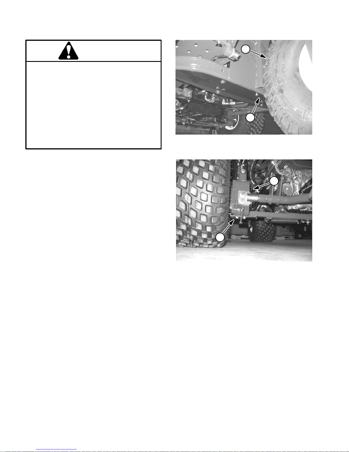
Use the following positions when jacking up the machine:
Front End Jacking
1. Jack the front of the machine from the bottom of the
frame behind the front wheel (Fig. 1). Make sure that
jack is positioned directly under frame to prevent damage to oil cooler.
1
2
Figure 1
1. Front wheel 2. Front jacking point
1
Rear End Jacking
1. Jack the rear of the machine from below the wheel
motor (Fig. 2).
Safety and Instruction Decals
Numerous safety and instruction decals are affixed to
the Sand Pro and Infield Pro. If any decal becomes illegible or damaged, install a new decal. Part numbers for
replacement decals are listed in your Parts Catalog. Order replacement decals from your Authorized Toro Distributor.
2
Figure 2
1. Rear wheel motor 2. Rear jacking point
Safety
Page 1 – 4
Sand Pro & Infield Pro 3040/5040
Page 9

Page 2 – 1 Product Records and MaintenanceSand Pro & Infield Pro 3040/5040
Chapter 2
Product Records and Maintenance
Table of Contents
PRODUCT RECORDS 1. . . . . . . . . . . . . . . . . . . . . . . . .
MAINTENANCE 1. . . . . . . . . . . . . . . . . . . . . . . . . . . . . .
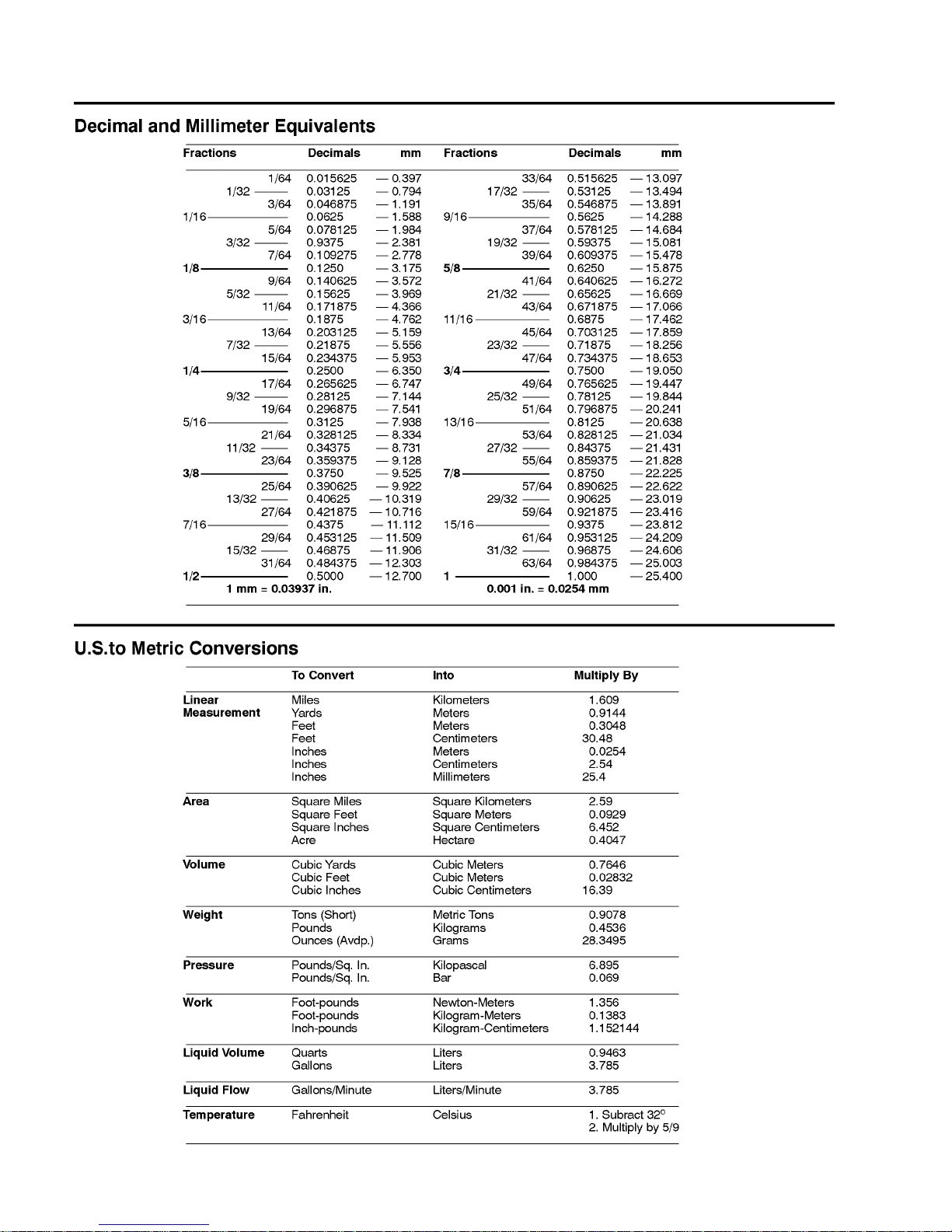
EQUIVALENTS AND CONVERSIONS 2. . . . . . . . . . .
Decimal and Millimeter Equivalents 2. . . . . . . . . . . .
U.S. to Metric Conversions 2. . . . . . . . . . . . . . . . . . .
TORQUE SPECIFICATIONS 3. . . . . . . . . . . . . . . . . . .
Fastener Identification 3. . . . . . . . . . . . . . . . . . . . . . .
Standard Torque for Dry, Zinc Plated and
Steel Fasteners (Inch Series) 4. . . . . . . . . . . . . . .
Standard Torque for Dry, Zinc Plated and
Steel Fasteners (Metric Fasteners) 5. . . . . . . . . .
Other Torque Specifications 6. . . . . . . . . . . . . . . . . .
Conversion Factors 6. . . . . . . . . . . . . . . . . . . . . . . . .
Product Records
Insert a copy of the Operator’s Manual and Parts Catalog for your Sand Pro or Infield Pro at the end of this
chapter. Additionally, if any optional equipment or accessories have been installed to your machine, insert
the Installation Instructions, Operator’s Manuals and
Parts Catalogs for those options at the end of this chapter.
Maintenance
Maintenance procedures and recommended service intervals for Sand Pro and Infield Pro machines are covered in the Operator’s Manual. Refer to that publication
when performing regular equipment maintenance.
Product Records
and Maintenance
Page 10
Page 2 – 2
Product Records and Maintenance
Sand Pro & Infield Pro 3040/5040
Equivalents and Conversions
Page 11
Page 2 – 3 Product Records and MaintenanceSand Pro & Infield Pro 3040/5040
Torque Specifications
Recommended fastener torque values are listed in the
following tables. For critical applications, as determined
by Toro, either the recommended torque or a torque that
is unique to the application is clearly identified and specified in this Service Manual.
These Torque Specifications for the installation and
tightening of fasteners shall apply to all fasteners which
do not have a specific requirement identified in this Service Manual. The following factors shall be considered
when applying torque: cleanliness of the fastener, use
of a thread sealant (e.g. Loctite), degree of lubrication
on the fastener, presence of a prevailing torque feature
(e.g. Nylock nut), hardness of the surface underneath
the fastener’s head or similar condition which affects the
installation.
As noted in the following tables, torque values should be
reduced by 25% for lubricated fasteners to achieve
the similar stress as a dry fastener. Torque values may
also have to be reduced when the fastener is threaded
into aluminum or brass. The specific torque value
should be determined based on the aluminum or brass
material strength, fastener size, length of thread engagement, etc.
The standard method of verifying torque shall be performed by marking a line on the fastener (head or nut)
and mating part, then back off fastener 1/4 of a turn.
Measure the torque required to tighten the fastener until
the lines match up.
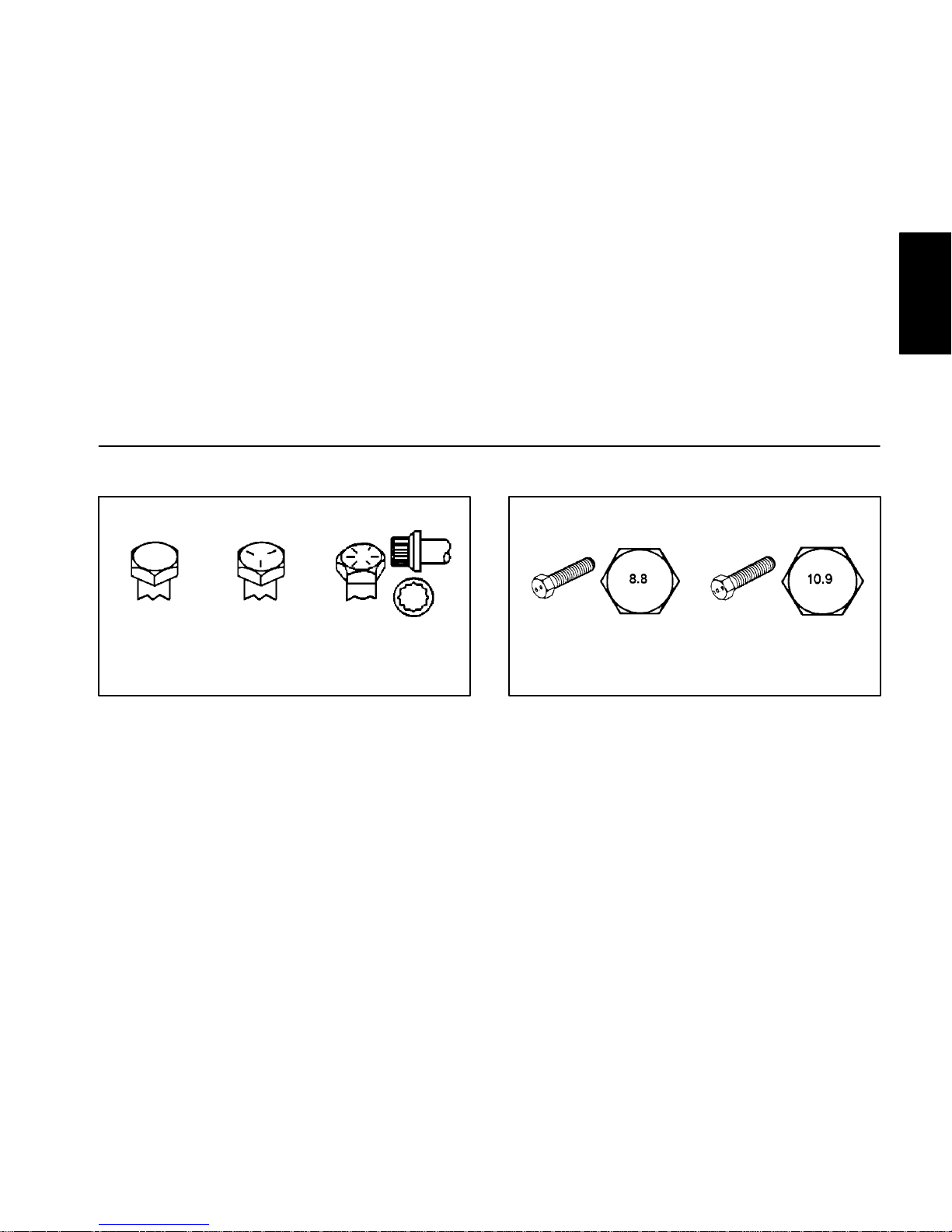
Fastener Identification
Figure 1
Grade 1 Grade 5 Grade 8
Inch Series Bolts and Screws
Figure 2
Class 8.8 Class 10.9
Metric Bolts and Screws
Product Records
and Maintenance
Page 12

Page 2 – 4
Product Records and Maintenance
Sand Pro & Infield Pro 3040/5040
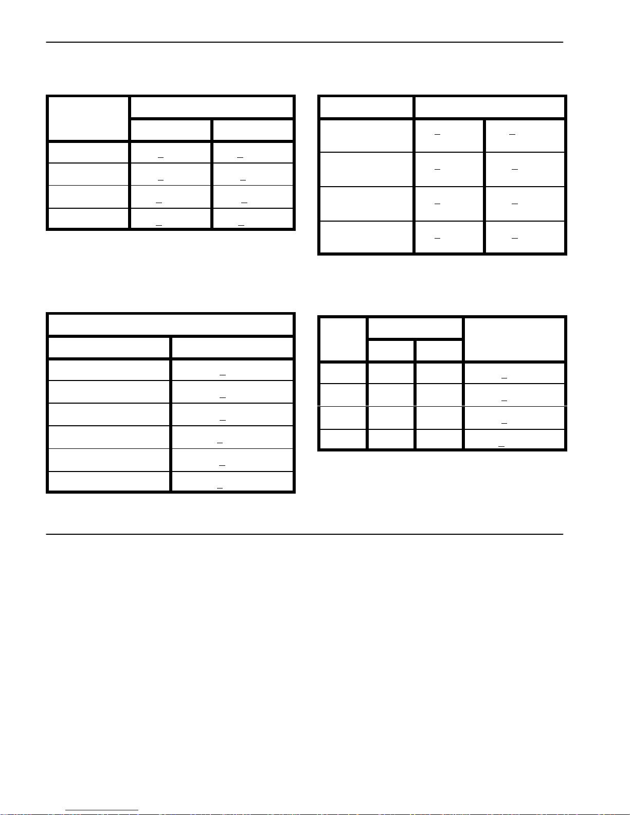
Standard Torque for Dry, Zinc Plated and Steel Fasteners (Inch Series)
Thread Size
Grade 1, 5 &
8 with Thin
Height Nuts
SAE Grade 1 Bolts, Screws, Studs &
Sems with Regular Height Nuts
(SAE J995 Grade 2 or Stronger Nuts)
SAE Grade 5 Bolts, Screws, Studs &
Sems with Regular Height Nuts
(SAE J995 Grade 2 or Stronger Nuts)
SAE Grade 8 Bolts, Screws, Studs &
Sems with Regular Height Nuts
(SAE J995 Grade 5 or Stronger Nuts)
in–lb in–lb N–cm in–lb N–cm in–lb N–cm
# 6 – 32 UNC
15 + 2 169 + 23 23 + 3 262 + 34
# 6 – 40 UNF
10 + 2 13 + 2 147 + 23
17 + 2 192 + 23 25 + 3 282 + 34
# 8 – 32 UNC
29 + 3 328 + 34 41 + 5 463 + 56
# 8 – 36 UNF
13 + 2 25 + 5 282 + 56
31 + 4 350 + 45 43 + 5 486 + 56
# 10 – 24 UNC
42 + 5 475 + 56 60 + 6 678 + 68
# 10 – 32 UNF
18 + 2 30 + 5 339 + 56
48 + 5 542 + 56 68 + 7 768 + 79
1/4 – 20 UNC 48 + 7 53 + 7 599 + 79 100 + 10 1130 + 113 140 + 15 1582 + 169
1/4 – 28 UNF 53 + 7 65 + 10 734 + 113 115 + 12 1299 + 136 160 + 17 1808 + 192
5/16 – 18 UNC 115 + 15 105 + 15 1186 + 169 200 + 25 2260 + 282 300 + 30 3390 + 339
5/16 – 24 UNF 138 + 17 128 + 17 1446 + 192 225 + 25 2542 + 282 325 + 33 3672 + 373
ft–lb ft–lb N–m ft–lb N–m ft–lb N–m
3/8 – 16 UNC 16 + 2 16 + 2 22 + 3 30 + 3 41 + 4 43 + 5 58 + 7
3/8 – 24 UNF 17 + 2 18 + 2 24 + 3 35 + 4 47 + 5 50 + 6 68 + 8
7/16 – 14 UNC 27 + 3 27 + 3 37 + 4 50 + 5 68 + 7 70 + 7 95 + 9
7/16 – 20 UNF 29 + 3 29 + 3 39 + 4 55 + 6 75 + 8 77 + 8 104 + 11
1/2 – 13 UNC 30 + 3 48 + 7 65 + 9 75 + 8 102 + 11 105 + 11 142 + 15
1/2 – 20 UNF 32 + 4 53 + 7 72 + 9 85 + 9 115 + 12 120 + 12 163 + 16
5/8 – 11 UNC 65 + 10 88 + 12 119 + 16 150 + 15 203 + 20 210 + 21 285 + 28
5/8 – 18 UNF 75 + 10 95 + 15 129 + 20 170 + 18 230 + 24 240 + 24 325 + 33
3/4 – 10 UNC 93 + 12 140 + 20 190 + 27 265 + 27 359 + 37 375 + 38 508 + 52
3/4 – 16 UNF 115 + 15 165 + 25 224 + 34 300 + 30 407 + 41 420 + 43 569 + 58
7/8 – 9 UNC 140 + 20 225 + 25 305 + 34 430 + 45 583 + 61 600 + 60 813 + 81
7/8 – 14 UNF 155 + 25 260 + 30 353 + 41 475 + 48 644 + 65 667 + 66 904 + 89
NOTE: Torque values may have to be reduced when
installing fasteners into threaded aluminum or brass.
The specific torque value should be determined based
on the fastener size, the aluminum or base material
strength, length of thread engagement, etc.
NOTE: Reduce torque values listed in the table above
by 25% for lubricated fasteners. Lubricated fasteners
are defined as threads coated with a lubricant such as
engine oil or thread sealant such as Loctite.
NOTE: The nominal torque values listed above for
Grade 5 and 8 fasteners are based on 75% of the minimum proof load specified in SAE J429. The tolerance is
approximately +
10% of the nominal torque value. Thin
height nuts include jam nuts.
Page 13

Page 2 – 5 Product Records and MaintenanceSand Pro & Infield Pro 3040/5040
Standard Torque for Dry, Zinc Plated and Steel Fasteners (Metric Fasteners)
Class 8.8 Bolts, Screws and Studs with
Class 10.9 Bolts, Screws and Studs with
Thread Size Regular Height Nuts
(Class 8 or Stronger Nuts)
Regular Height Nuts
(Class 10 or Stronger Nuts)
M5 X 0.8 57 + 6 in–lb 644 + 68 N–cm 78 + 8 in–lb 881 + 90 N–cm
M6 X 1.0 96 + 10 in–lb 1085 + 113 N–cm 133 + 14 in–lb 1503 + 158 N–cm
M8 X 1.25 19 + 2 ft–lb 26 + 3 N–m 28 + 3 ft–lb 38 + 4 N–m
M10 X 1.5 38 + 4 ft–lb 52 + 5 N–m 54 + 6 ft–lb 73 + 8 N–m
M12 X 1.75 66 + 7 ft–lb 90 + 10 N–m 93 + 10 ft–lb 126 + 14 N–m
M16 X 2.0 166 + 17 ft–lb 225 + 23 N–m 229 + 23 ft–lb 310 + 31 N–m
M20 X 2.5 325 + 33 ft–lb 440 + 45 N–m 450 + 46 ft–lb 610 + 62 N–m
NOTE: Torque values may have to be reduced when
installing fasteners into threaded aluminum or brass.
The specific torque value should be determined based
on the fastener size, the aluminum or base material
strength, length of thread engagement, etc.
NOTE: Reduce torque values listed in the table above
by 25% for lubricated fasteners. Lubricated fasteners
are defined as threads coated with a lubricant such as
engine oil or thread sealant such as Loctite.
NOTE: The nominal torque values listed above are
based on 75% of the minimum proof load specified in
SAE J1199. The tolerance is approximately +
10% of the
nominal torque value.
Product Records
and Maintenance
Page 14
Page 2 – 6
Product Records and Maintenance
Sand Pro & Infield Pro 3040/5040
Other Torque Specifications
SAE Grade 8 Steel Set Screws
Recommended Torque
Thread Size
Square Head Hex Socket
1/4 – 20 UNC 140 + 20 in–lb 73 + 12 in–lb
5/16 – 18 UNC 215 + 35 in–lb 145 + 20 in–lb
3/8 – 16 UNC 35 + 10 ft–lb 18 + 3 ft–lb
1/2 – 13 UNC 75 + 15 ft–lb 50 + 10 ft–lb
Thread Cutting Screws
(Zinc Plated Steel)
Type 1, Type 23 or Type F
Thread Size Baseline Torque*
No. 6 – 32 UNC 20 + 5 in–lb
No. 8 – 32 UNC 30 + 5 in–lb
No. 10 – 24 UNC 38 + 7 in–lb
1/4 – 20 UNC 85 + 15 in–lb
5/16 – 18 UNC 110 + 20 in–lb
3/8 – 16 UNC 200 + 100 in–lb
Wheel Bolts and Lug Nuts
Thread Size
Recommended Torque**
7/16 – 20 UNF
Grade 5
65 + 10 ft–lb 88 + 14 N–m
1/2 – 20 UNF
Grade 5
80 + 10 ft–lb 108 + 14 N–m
M12 X 1.25
Class 8.8
80 + 10 ft–lb 108 + 14 N–m
M12 X 1.5
Class 8.8
80 + 10 ft–lb 108 + 14 N–m
** For steel wheels and non–lubricated fasteners.
Thread Cutting Screws
(Zinc Plated Steel)
Thread
Threads per Inch
Size
Type A Type B
Baseline Torque*
No. 6 18 20 20 + 5 in–lb
No. 8 15 18 30 + 5 in–lb
No. 10 12 16 38 + 7 in–lb
No. 12 11 14 85 + 15 in–lb
* Hole size, material strength, material thickness & finish
must be considered when determining specific torque
values. All torque values are based on non–lubricated
fasteners.
Conversion Factors
in–lb X 11.2985 = N–cm N–cm X 0.08851 = in–lb
ft–lb X 1.3558 = N–m N–m X 0.7376 = ft–lb
Page 15

Gasoline EnginePage 3 – 1Sand Pro & Infield Pro 3040/5040
Chapter 3
Gasoline Engine
Table of Contents
INTRODUCTION 2. . . . . . . . . . . . . . . . . . . . . . . . . . . . . .
SPECIFICATIONS 3. . . . . . . . . . . . . . . . . . . . . . . . . . . .
GENERAL INFORMATION 4. . . . . . . . . . . . . . . . . . . . .
Fuel Shut–off Valve 4. . . . . . . . . . . . . . . . . . . . . . . . . .
SERVICE AND REPAIRS 5. . . . . . . . . . . . . . . . . . . . . .
Cooling System 5. . . . . . . . . . . . . . . . . . . . . . . . . . . . .
Air Cleaner Assembly 6. . . . . . . . . . . . . . . . . . . . . . . .
Fuel Tank 8. . . . . . . . . . . . . . . . . . . . . . . . . . . . . . . . . .
Engine 10. . . . . . . . . . . . . . . . . . . . . . . . . . . . . . . . . . . .
Engine Removal 10. . . . . . . . . . . . . . . . . . . . . . . . . .
Engine Installation 12. . . . . . . . . . . . . . . . . . . . . . . .
BRIGGS & STRATTON REPAIR MANUAL FOR
4–CYCLE, V–TWIN CYLINDER, OHV HEAD ENGINES
Gasoline
Engine
Page 16

Gasoline Engine Page 3 – 2 Sand Pro & Infield Pro 3040/5040
Introduction
This Chapter gives information about specifications,
maintenance, troubleshooting, testing and repair of the
Briggs and Stratton gasoline engine used in Sand Pro
and Infield Pro machines.
Most repairs and adjustments require tools which are
commonly available in many service shops. Special
tools are described in the Briggs and Stratton Repair
Manual that is included at the end of this Chapter. The
use of some specialized test equipment is explained.
However, the cost of the test equipment and the specialized nature of some repairs may dictate that the work be
done at an engine repair facility.
Service and repair parts for the Briggs and Stratton engine used to power the Sand Pro or Infield Pro are supplied through your local Toro distributor or your local
Briggs and Stratton dealer or distributor. If no parts list
is available, be prepared to provide your distributor with
the Toro equipment model and serial numbers as well as
the Briggs and Stratton engine model and serial numbers.
Page 17

Gasoline EnginePage 3 – 3Sand Pro & Infield Pro 3040/5040
Specifications
Item Description
Engine Make / Designation Briggs and Stratton, 4–cycle, V–Twin Cylinder,
OHV, Air Cooled, Gasoline Engine
Bore x Stroke
Sand Pro & Infield Pro 3040 2.68” x 2.60” (68mm x 66mm)
Sand Pro & Infield Pro 5040 2.83” x 2.75” (72mm x 70mm)
Engine Displacement
Sand Pro & Infield Pro 3040 29.3 cu in (480cc)
Sand Pro & Infield Pro 5040 34.8 cu in (570cc)
Fuel Unleaded Regular Grade Gasoline
Fuel Capacity 5.0 US gallons (18.9 liters)
Fuel Pump Pulsating Crankcase Vacuum
Carburetor Float Feed, Single Barrel
Governor Mechanical
High Idle Speed (No Load) 3400 + 50 RPM
Low Idle Speed (No Load) 1750 + 100 RPM
Lubrication System Pressure Lubrication
Oil Pump Gear Driven Geroter Type
Crankcase Oil Capacity 1.75 US quarts (1.66 liters) with new filter
Engine Oil See Operator’s Manual
Spark Plugs Champion RC 14YC (or equivalent)
Spark Plug Gap 0.030” (0.76mm)
Starter 12 VDC
Alternator 12 VDC / 15 Amps
Engine Weight (approximate)
Sand Pro & Infield Pro 3040 72 lb (32.7 kg)
Sand Pro & Infield Pro 5040 74 lb (33.6 kg)
Gasoline
Engine
Page 18
Gasoline Engine Page 3 – 4 Sand Pro & Infield Pro 3040/5040
General Information
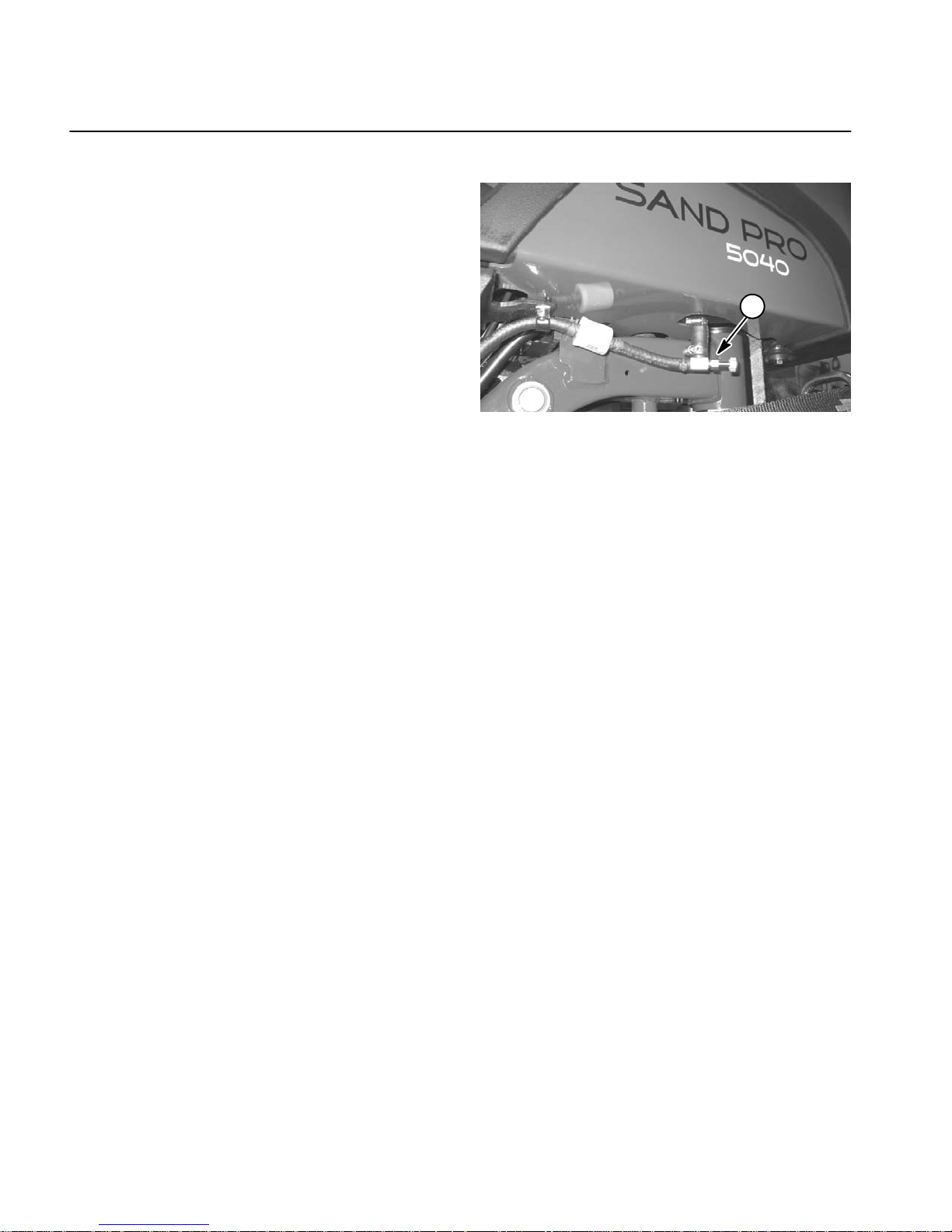
Fuel Shut Off Valve
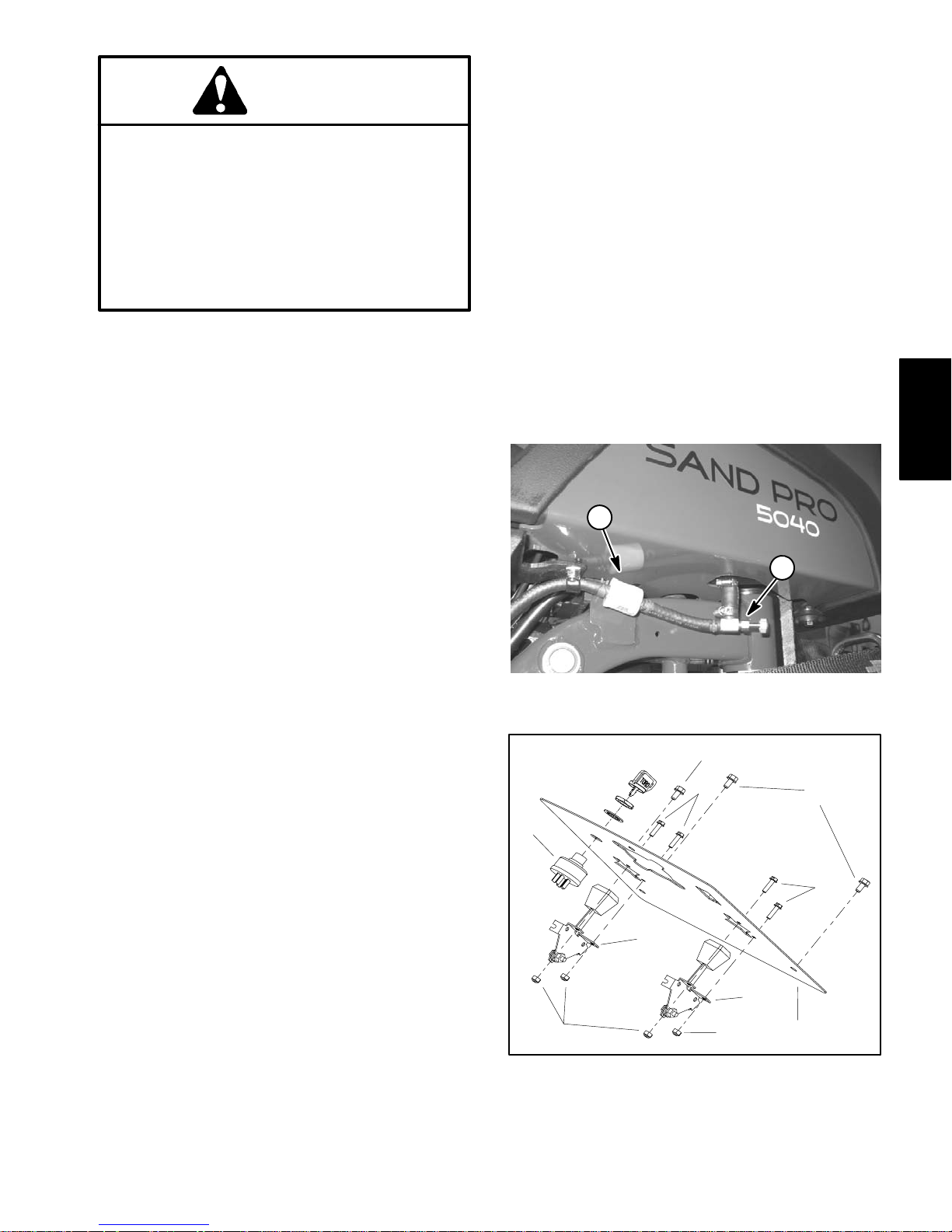
The fuel shut off valve located under the fuel tank (Fig.
1) should be closed if the machine is being transported
on a trailer or when placing the machine in long term
storage. Additionally, close the shut off valve when removing the fuel tank or engine from the machine.
Figure 1
1. Fuel shut–off valve
1
Page 19

Gasoline EnginePage 3 – 5Sand Pro & Infield Pro 3040/5040
Service and Repairs
Cooling System
To ensure proper engine cooling, make sure the rotating
screen, cooling fins and other external surfaces of the
engine are kept clean at all times.
NOTE: Perform this maintenance procedure at the interval specified in the Operator’s Manual.
IMPORTANT: The engine that powers Sand Pro and
Infield Pro machines is air–cooled. Operating the
engine with dirty or plugged cooling fins, a blocked
rotating screen or a plugged or dirty blower housing
will result in engine overheating and engine damage.
1. Park machine on a level surface, lower attachment,
stop engine, apply parking brake and remove key from
ignition switch.
CAUTION
The engine and exhaust system may be hot. To
avoid possible burns, allow the engine and exhaust system to cool before working on the engine.
IMPORTANT: Never clean engine with pressurized
water. Water could enter and contaminate the fuel
system.
2. Clean cooling fins on both cylinder heads.
3. Clean rotating screen and blower housing of dirt and
debris (Fig. 2).
4. If blower housing removal is necessary for cooling
system cleaning, engine needs to be removed from machine (see Engine Removal and Installation in this section).
IMPORTANT: Never operate engine without the
blower housing installed. Overheating and engine
damage will result.
5. Make sure rotating screen and blower housing are
reinstalled to the engine if removed.
Figure 2
1. Cylinder head
2. Rotating screen
3. Blower housing
2
1
1
3
Gasoline
Engine
Page 20
Gasoline Engine Page 3 – 6 Sand Pro & Infield Pro 3040/5040
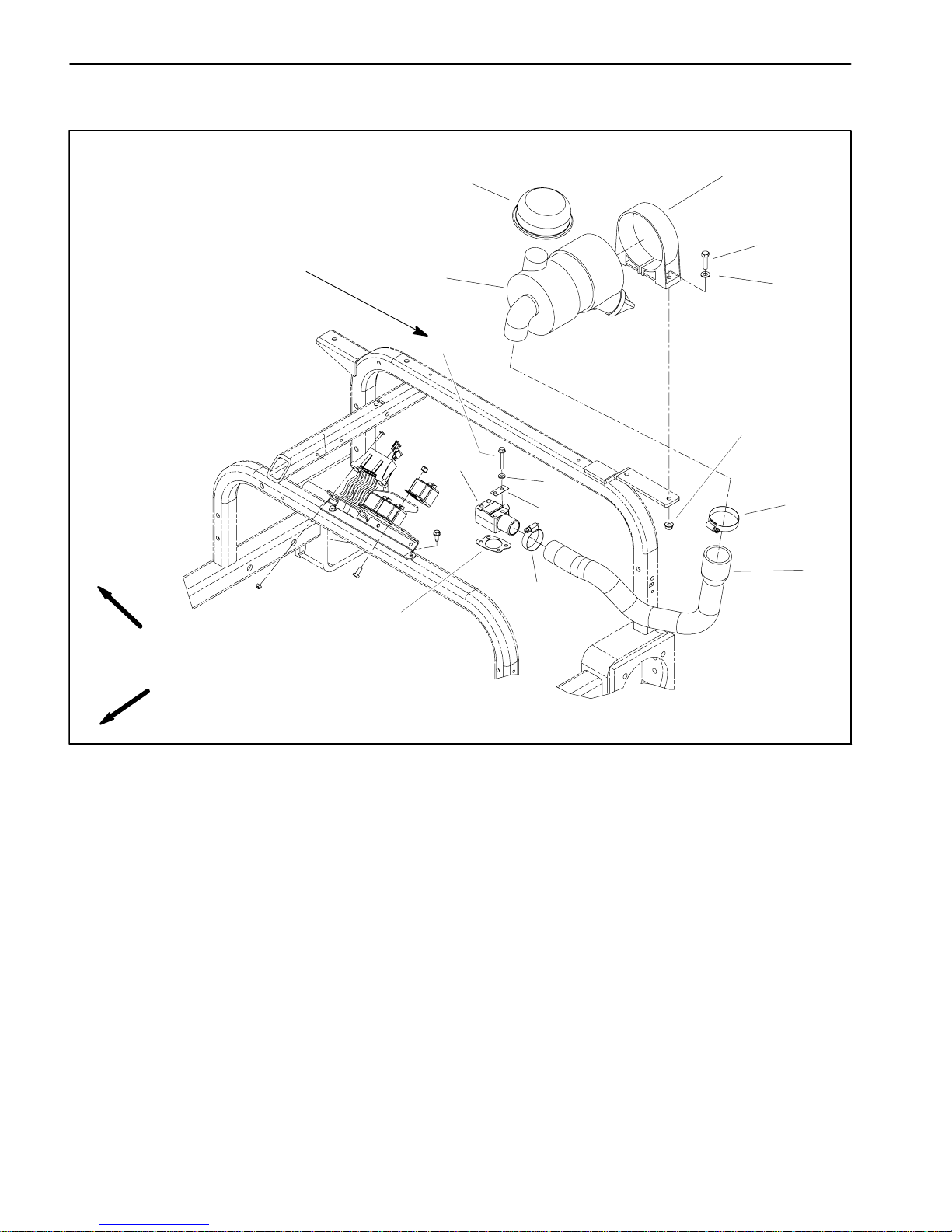
Air Cleaner Assembly
1. Inlet hood
2. Air cleaner assembly
3. Intake elbow
4. Hose clamp
5. Cap screw (2 used)
6. Flat washer (2 used)
7. Mounting bracket
8. Lock nut (2 used)
9. Hose clamp
10. Air hose
11. Flange head screw (4 used)
12. Flat washer (4 used)
13. Gasket (2 used)
14. Intake gasket
Figure 3
FRONT
RIGHT
5
6
7
1
3
8
2
10
4
9
11
12
13
60 to 65 in–lb
(6.8 to 7.3 N–m)
14
Page 21
Gasoline EnginePage 3 – 7Sand Pro & Infield Pro 3040/5040
Removal (Fig. 3)
NOTE: See Operator’s Manual for air cleaner mainte-
nance procedures and intervals.
1. Park machine on a level surface, lower attachment,
stop engine, apply parking brake and remove key from
ignition switch.
2. Remove air cleaner components as needed using
Figure 3 as a guide.
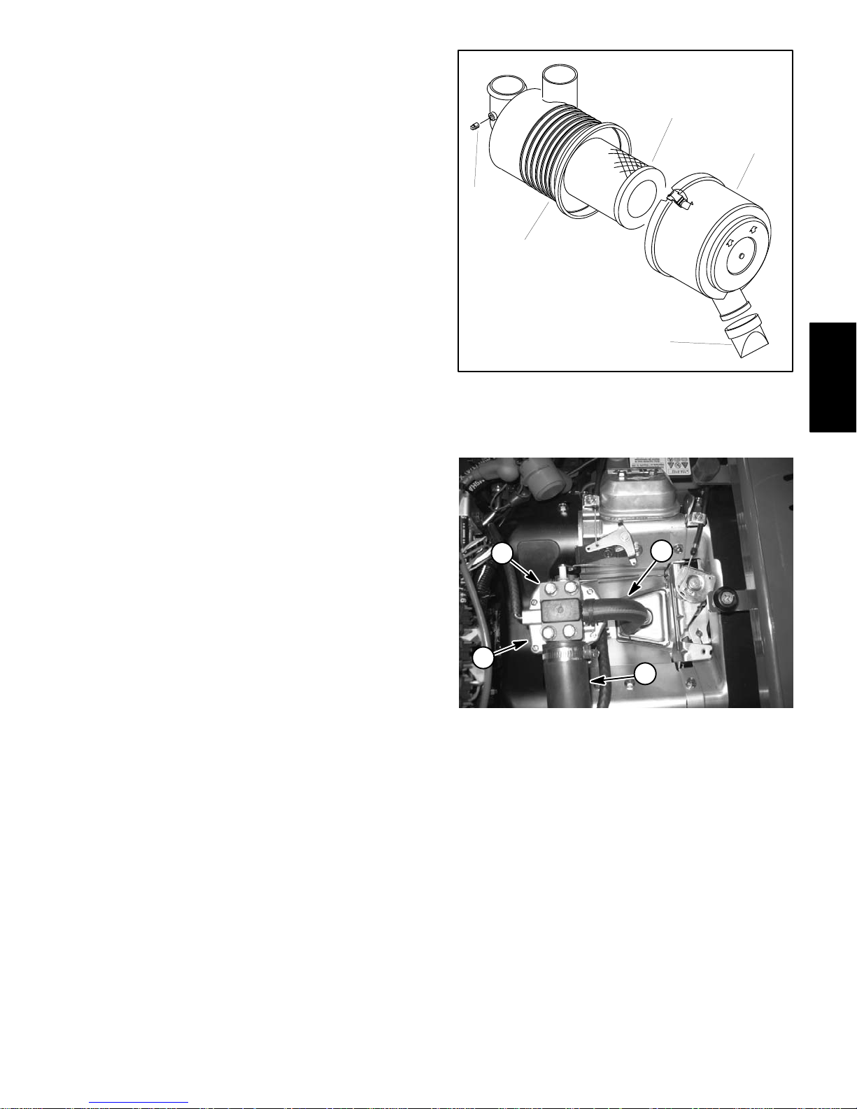
3. Check air cleaner assembly for damage that could
cause possible air leaks (Fig. 4). Make sure that air
cleaner cover seals completely to the air cleaner housing.
Installation (Fig. 3)
IMPORTANT: Any leaks in the air filter system will
allow dirt into the engine and will cause serious engine damage. Make sure that all air cleaner components are in good condition and are properly
secured during assembly.
1. Assemble air cleaner system using Figure 3 as a
guide. Make sure that vacuator valve is pointed down after assembly (Fig. 4).
1. Air cleaner housing
2. Pipe plug
3. Filter element
4. Air cleaner cover
5. Vacuator valve
Figure 4
5
4
3
2
1
1. Air hose
2. Breather tube
3. Intake elbow
4. Carburetor
Figure 5
3
1
2
4
Gasoline
Engine
Page 22
Gasoline Engine Page 3 – 8 Sand Pro & Infield Pro 3040/5040
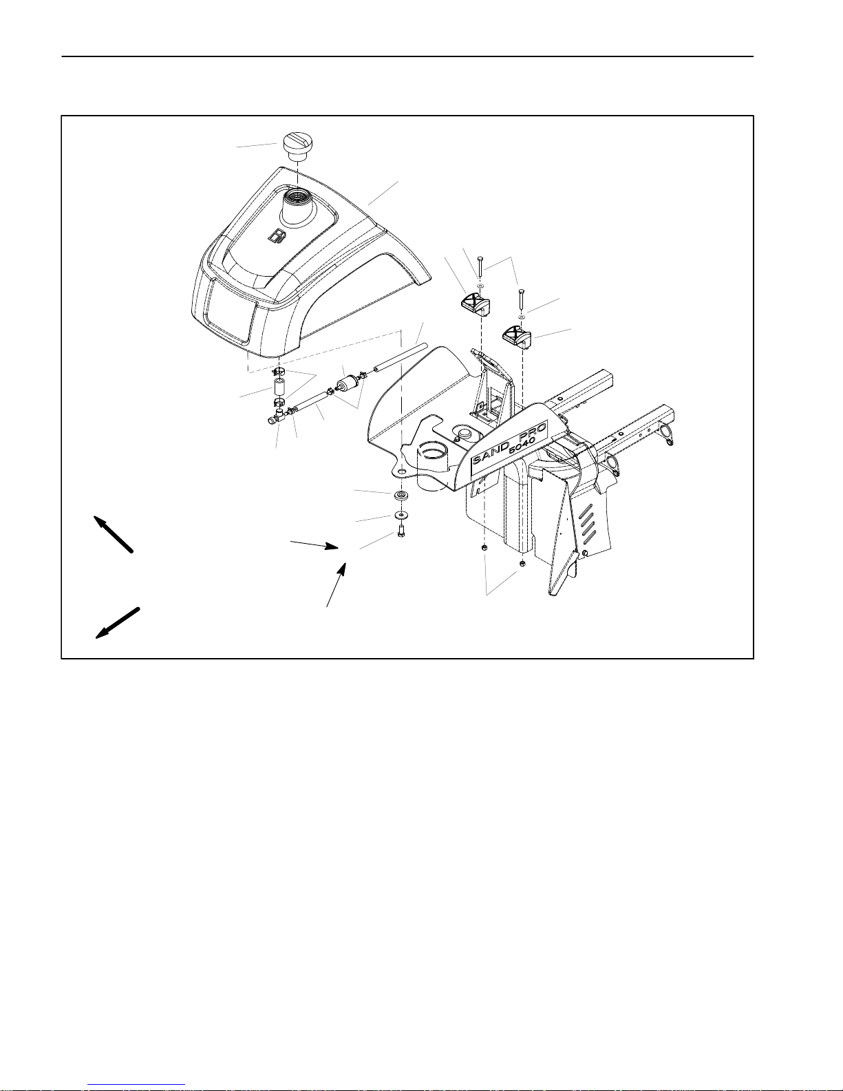
Fuel Tank
1. Fuel cap
2. Fuel tank
3. Cap screw
4. Clamp
5. Fuel hose
6. Fuel filter
7. Hose clamp
8. Fuel hose
9. Fuel shut off valve
10. Hose clamp
11. Fuel hose
12. Flange bushing
13. Washer
14. Cap screw
15. Lock nut
16. Flat washer
Figure 6
FRONT
RIGHT
30 to 60 in–lb
(3.4 to 6.8 N–m)
13
12
9
11
5
7
8
6
4
3
2
1
10
4
10
14
15
ANTISEIZE
LUBRICANT
16
16
Page 23
Gasoline EnginePage 3 – 9Sand Pro & Infield Pro 3040/5040
DANGER
Because gasoline is highly flammable, use caution when storing or handling it. Do not smoke
while filling the fuel tank. Do not fill fuel tank
while engine is running, hot or when machine is
in an enclosed area. Always fill fuel tank outside
and clean up any spilled fuel before starting the
engine. Store fuel in a clean, safety–approved
container and keep fuel cap in place. Use gasoline for the engine only; not for any other
purpose.
Check Fuel Lines and Connections
Check fuel lines and connections periodically as recommended in the Operator’s Manual. Check lines for deterioration, damage, leaks or loose connections. Replace
hoses, clamps and connections as necessary.
Drain and Clean Fuel Tank
IMPORTANT: If fuel tank is to be drained, drain fuel
outdoors.
Drain and clean the fuel tank periodically as recommended in the Operator’s Manual. Also, drain and clean
the fuel tank if the fuel system becomes contaminated
or if the machine is to be stored for an extended period.
To clean fuel tank, flush tank and fuel hoses out with
clean solvent. Make sure tank is free of contaminates
and debris.
Fuel Tank Removal (Fig. 6)
1. Park machine on a level surface, lower attachment,
stop engine, apply parking brake and remove key from
ignition switch.
2. Close fuel shut off valve (Fig. 7). Disconnect fuel
hose from fuel filter inlet.
3. Place disconnected hose in appropriate container
and open fuel shut off valve to allow fuel tank to drain
completely.
4. Remove three (3) washer head screws that retain
dash panel to fuel tank (Fig. 8). Carefully position panel
away from fuel tank.
5. Remove fuel tank from machine using Figure 6 as a
guide.
6. If fuel in tank was contaminated, carburetor removal
and cleaning may be necessary (see Briggs and Stratton Repair Manual at the end of this chapter).
Fuel Tank Installation (Fig. 6)
1. If carburetor was removed from engine for cleaning,
install carburetor (see Briggs and Stratton Repair Manual at the end of this chapter).
2. Install fuel tank to frame using Figure 6 as a guide.
Apply antiseize lubricant to cap screw (item 14) that secures front of fuel tank to machine. Install and torque cap
screw from 30 to 60 in–lb (3.4 to 6.8 N–m).
3. Connect fuel hose to fuel filter inlet. Make sure that
fuel hose is secured with hose clamps.
4. Position panel to fuel tank and secure with three (3)
washer head screws (Fig. 8).
5. Fill fuel tank (see Operator’s Manual).
6. Open fuel shut off valve and check for any signs of
fuel leakage.
1. Fuel shut off valve 2. Fuel filter
Figure 7
1
2
1. Washer head screw
2. Screw
3. Dash panel
4. Choke lever/cable
5. Lock nut
6. Throttle lever/cable
7. Ignition switch
Figure 8
5
7
6
4
3
2
1
1
2
5
Gasoline
Engine
Page 24
Gasoline Engine Page 3 – 10 Sand Pro & Infield Pro 3040/5040
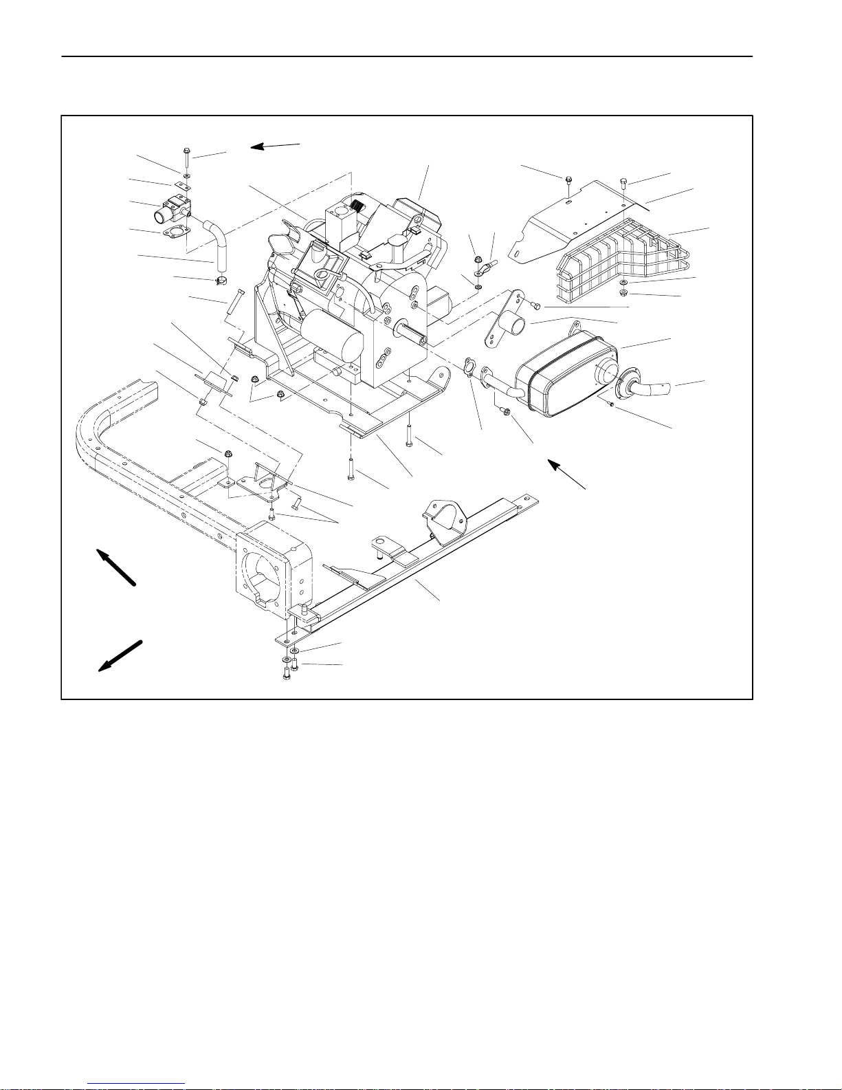
Engine
Figure 9
1. Muffler shield
2. Negative battery cable
3. Engine
4. Hose clamp (2 used)
5. Engine support
6. Cap screw (4 used)
7. Engine mount (4 used)
8. Front mount bracket (2 used)
9. Flange nut (4 used)
10. Cap screw
11. Flange nut
12. Engine mount
13. Cap screw (4 used)
14. Lock washer
15. Cap screw (4 used)
16. Crankshaft cover
17. Cap screw (2 used)
18. Breather tube
19. Intake gasket
20. Flange head screw (3 used)
21. Flat washer (4 used)
22. Hose
23. Flange head screw (4 used)
24. Washer head screw (4 used)
25. Gasket (2 used)
26. Muffler
27. Intake elbow
28. Tail pipe
29. Flat washer (4 used)
30. Cap screw (3 used)
31. Flange head screw (4 used)
32. Exhaust gasket (2 used)
33. Flat washer (3 used)
34. Flange nut (3 used)
35. Exhaust shield
FRONT
LEFT
170 to 200 in–lb
(19.2 to 22.6 N–m)
60 to 65 in–lb
(6.8 to 7.3 N–m)
35
24
1
26
16
17
11
5
12
29
13
7
8
9
15
3
6
28
11
10
22
20
21
31
32
34
33
30
23
25
27
19
18
11
15
2
11
14
4
Engine Removal (Fig. 9)
1. Park machine on a level surface, lower attachment,
stop engine, apply parking brake and remove key from
ignition switch.
2. If engine is to be disassembled, it may be easier to
drain oil from engine before removing engine from machine (see Operator’s Manual).
3. Chock wheels to prevent the machine from moving.
Page 25
Gasoline EnginePage 3 – 11Sand Pro & Infield Pro 3040/5040
4. Remove rear attachment from machine.
CAUTION
The engine and exhaust system may be hot. To
avoid possible burns, allow the engine and exhaust system to cool before removing engine
from machine.
5. Remove hitch assembly from the rear of the machine
(see Hitch Assembly Removal in the Service and Repairs section of Chapter 6 – Chassis).
6. Raise operator seat.
CAUTION
When disconnecting the battery cables from the
battery, make sure to remove the negative (–) battery cable first and then remove the positive (+)
battery cable.
7. Disconnect and remove battery from the machine to
prevent the possibility of the engine damaging it during
removal (see Battery Service in the Service and Repairs
section of Chapter 5 – Electrical Systems).
8. Close fuel shutoff valve. Clamp fuel hose near
engine to prevent fuel spillage. Loosen hose clamp at
fuel pump and remove fuel hose from the pump.
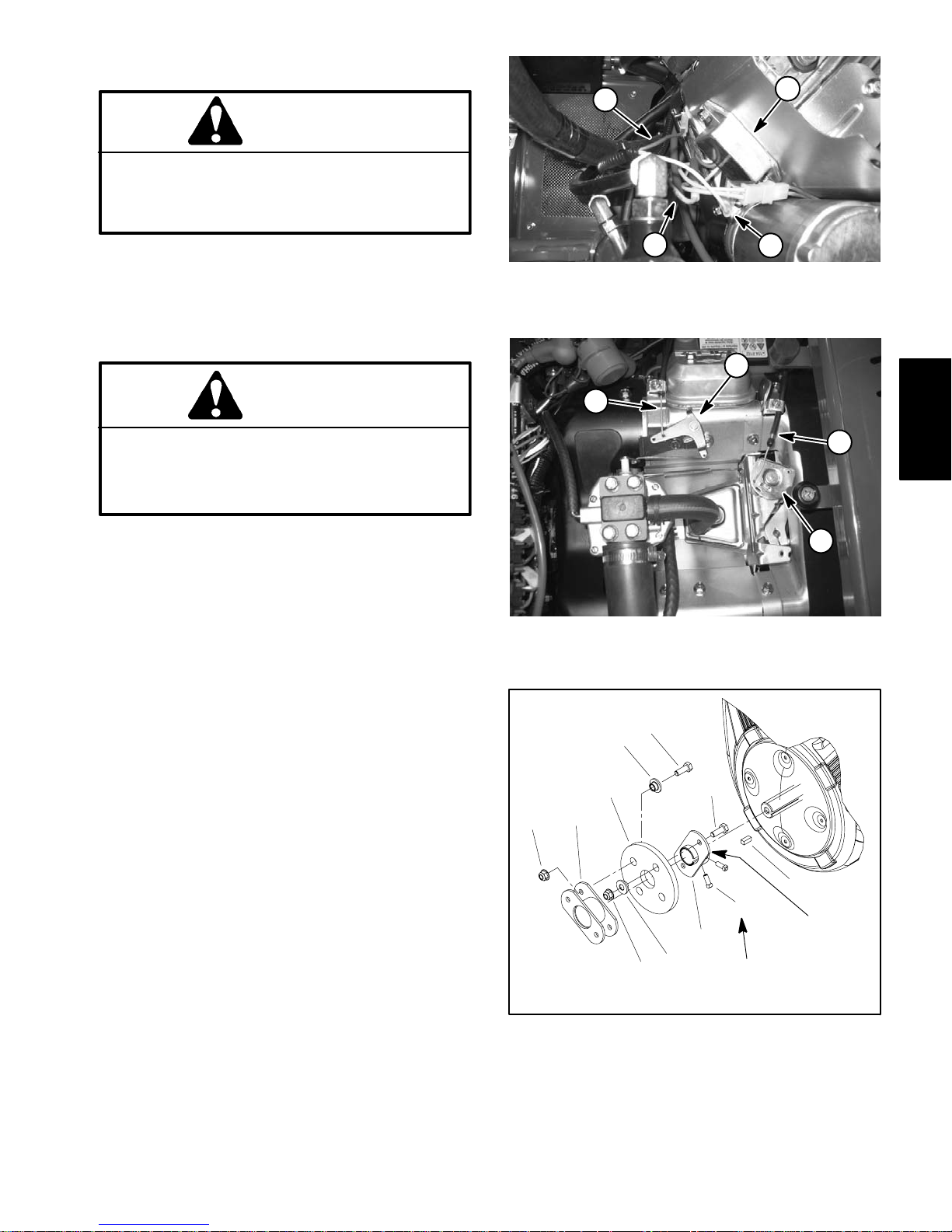
9. Disconnect machine wire harness from engine as
follows (Fig. 10):
A. Disconnect harness violet wire from engine magneto terminal.
B. Disconnect harness fusible link from voltage regulator on engine blower housing.
C. Disconnect harness yellow wire from engine fuel
solenoid lead.
10.Remove air intake hose from air cleaner assembly
and engine intake elbow (see Air Cleaner Assembly Removal in this section).
11. Disconnect breather tube from intake elbow.
12.Remove four (4) flange head screws that secure intake elbow to carburetor. Remove two (2) gaskets and
intake manifold. Discard gaskets. Remove and discard
intake gasket from between intake elbow and carburetor. Make sure that all gasket material is removed from
carburetor and intake elbow.
Figure 10
1. Violet wire (magneto)
2. Fusible link (voltage reg.)
3. Voltage regulator
4. Yellow wire
1
2
4
3
1. Throttle control cable
2. Governor control plate
3. Choke cable
4. Choke lever
Figure 11
3
1
2
4
1. Square key
2. Cap screw
3. Set screw
4. Engine hub
5. Coupling spacer
6. Lock nut
7. Drive coupling
8. Coupling
Figure 12
7
8
2
4
3
1
2
5
5
6
6
Loctite #242
Antiseize
Lubricant
90 to 110 in–lb
(10.2 to 12.4 N–m)
Gasoline
Engine
Page 26
Gasoline Engine Page 3 – 12 Sand Pro & Infield Pro 3040/5040
13.Disconnect throttle control cable from the governor
control plate and choke control cable from the choke lever (Fig. 11).
14.Disconnect red positive cable (solenoid) from the
starter motor.
15.Loosen two (2) set screws on the engine hub to allow
hub removal from the engine stub shaft (Fig. 12).
16.Remove lock nut and cap screw securing engine and
negative battery cable to the engine support. Locate and
retrieve lock washer (item 14). Position cable away from
engine.
17.Remove remaining three (3) lock nuts and cap
screws that secure the engine to the engine support.
IMPORTANT: Make sure not to damage the engine,
fuel lines, hydraulic lines, electrical harness or other parts while removing the engine from the machine.
18.Remove engine from machine as follows:
A. Slide engine toward the rear of machine to remove engine stub shaft from engine hub. Take care
not to damage the hydrostat coupling.
B. Once the engine stub shaft is clear of the engine
hub, remove engine from the rear of the machine.
C. Locate and retrieve square key from the engine
stub shaft.
Engine Installation (Fig. 9)
1. Position machine on a level surface.
2. Make sure that all parts removed from the engine
during maintenance or rebuilding are properly installed
to the engine.
IMPORTANT: Make sure not to damage the engine,
fuel lines, hydraulic lines, electrical harness or other parts while installing the engine.
3. Install engine to machine as follows:
A. Apply antiseize lubricant to bore of engine hub.
Place square key into slot on the engine stub shaft.
B. Position engine onto engine support from the rear
of the machine.
C. Align engine stub shaft to engine hub. Slide engine toward the front of machine until mounting holes
in engine align with holes in engine support. Take
care not to damage the hydrostat coupling.
D. Install three (3) cap screws and lock nuts to secure the engine to the engine support. Do not fully
tighten lock nuts.
E. Position lock washer and negative battery cable
to the engine. Lock washer should be positioned between engine and ground cable. Install fourth cap
screw up through engine support, engine, lock washer and ground cable and then install lock nut. Do not
fully tighten lock nut.
F. Rotate engine crankshaft by hand and check for
deflection of pump couplers that would indicate misalignment between engine and hydrostat. Position
engine on engine support to best align the coupling
assembly.
G. Tighten four (4) cap screws and lock nuts to secure engine to machine.
4. Position engine hub on engine stub shaft so that rubber pump drive couplings are not distorted. Apply Loctite
#242 (or equivalent) to threads of engine hub set
screws. Tighten both set screws on the engine hub to
secure hub to the engine stub shaft (Fig. 12). Torque set
screws from 90 to 110 in–lb (10.2 to 12.4 N–m).
5. Connect throttle control cable to the governor control
plate and choke control cable to the choke lever (Fig.
11).
6. Connect positive cable (solenoid) to starter motor.
7. Connect machine wire harness leads to engine as
follows (Fig. 10):
A. Connect harness violet wire to the engine magneto terminal.
B. Connect harness fusible link to voltage regulator
on engine blower housing.
C. Connect harness yellow wire to engine fuel solenoid lead.
CAUTION
When connecting the battery cables to the battery, make sure to attach the positive (+) battery
cable first and then attach the negative (–) battery cable.
8. Install and connect battery to the machine (see Battery Service in the Service and Repairs section of Chapter 5 – Electrical Systems).
Page 27

Gasoline EnginePage 3 – 13Sand Pro & Infield Pro 3040/5040
9. Secure fuel hose to the fuel pump with hose clamp.
Remove clamp from fuel hose that was used to prevent
fuel spillage. Open fuel shutoff valve.
10.Place new intake gasket on carburetor. Position intake elbow to top of carburetor. Place two (2) gaskets to
top of intake elbow and secure intake elbow with four (4)
flange head screws. Torque cap screws from 60 to 65
in–lbs (6.8 to 7.3 N–m).
IMPORTANT: Any leaks in the air filter system will
allow dirt into engine and will cause serious engine
damage. Make sure that all air cleaner components
and breather tube are in good condition and are
properly secured during assembly.
11. Secure breather tube to intake elbow. Make sure that
hose clamps are properly tightened.
12.Secure air intake hose to air cleaner assembly and
engine (see Air Cleaner Assembly Installation in this
section). Make sure that hose clamps are properly tightened.
13.Install hitch assembly to the rear of the machine (see
Hitch Assembly Installation in the Service and Repairs
section of Chapter 6 – Chassis).
14.Install attachment to the machine.
15.Lower operator seat.
16.Check and adjust engine oil level (See Operator’s
Manual).
17.Check operation of choke and throttle cables. Adjust
if necessary (see Operator’s Manual).
Gasoline
Engine
Page 28

Gasoline Engine Page 3 – 14 Sand Pro & Infield Pro 3040/5040
This page is intentionally blank.
Page 29

Sand Pro & Infield Pro 3040/5040 Page 4 – 1 Hydraulic System
Chapter 4
Hydraulic System
Table of Contents
SPECIFICATIONS 2. . . . . . . . . . . . . . . . . . . . . . . . . . . .
GENERAL INFORMATION 3. . . . . . . . . . . . . . . . . . . . .
Hydraulic Hoses 3. . . . . . . . . . . . . . . . . . . . . . . . . . . .
Hydraulic Fitting Installation 3. . . . . . . . . . . . . . . . . .
Towing 5. . . . . . . . . . . . . . . . . . . . . . . . . . . . . . . . . . . . .
Relieving Hydraulic System Pressure 5. . . . . . . . . .
Traction Circuit Component Failure 5. . . . . . . . . . . .
Optional Hydraulic Accessories 5. . . . . . . . . . . . . . .
HYDRAULIC SCHEMATICS 6. . . . . . . . . . . . . . . . . . . .
Sand Pro 3040 and Infield Pro 3040 6. . . . . . . . . . .
Sand Pro 3040 and Infield Pro 3040 (Including
Optional Hydraulic Kits) 7. . . . . . . . . . . . . . . . . . . .
Sand Pro 5040 and Infield Pro 5040 8. . . . . . . . . . .
Sand Pro 5040 and Infield Pro 5040 (Including
Optional Hydraulic Kits) 9. . . . . . . . . . . . . . . . . . . .
HYDRAULIC FLOW DIAGRAMS 10. . . . . . . . . . . . . . .
Traction Circuit 10. . . . . . . . . . . . . . . . . . . . . . . . . . . .
Lift Circuit 12. . . . . . . . . . . . . . . . . . . . . . . . . . . . . . . . .
Steering Circuit 14. . . . . . . . . . . . . . . . . . . . . . . . . . . .
SPECIAL TOOLS 16. . . . . . . . . . . . . . . . . . . . . . . . . . . .
TROUBLESHOOTING 19. . . . . . . . . . . . . . . . . . . . . . . .
TESTING 21. . . . . . . . . . . . . . . . . . . . . . . . . . . . . . . . . . .
Charge Pressure and Implement Relief
Valve (R1) Pressure Tests 22. . . . . . . . . . . . . . . . .
Traction Relief Valve (R3) Pressure Test 24. . . . . .
Traction Pump (P1) Flow Test 26. . . . . . . . . . . . . . . .
Wheel Motor Efficiency Test 28. . . . . . . . . . . . . . . . .
Charge Pump (P2) Flow Test 30. . . . . . . . . . . . . . . .
Steering Cylinder Internal Leakage Test
(Sand Pro 5040 and Infield Pro 5040) 32. . . . . . .
SERVICE AND REPAIRS 34. . . . . . . . . . . . . . . . . . . . .
General Precautions for Removing and
Installing Hydraulic System Components 34. . . .
Check Hydraulic Lines and Hoses 34. . . . . . . . . . . .
Flush Hydraulic System 35. . . . . . . . . . . . . . . . . . . . .
Charge Hydraulic System 36. . . . . . . . . . . . . . . . . . .
Hydraulic Tank 38. . . . . . . . . . . . . . . . . . . . . . . . . . . . .
Oil Cooler 40. . . . . . . . . . . . . . . . . . . . . . . . . . . . . . . . .
Front Wheel Motor 42. . . . . . . . . . . . . . . . . . . . . . . . .
Rear Wheel Motor 44. . . . . . . . . . . . . . . . . . . . . . . . . .
Wheel Motor Service 46. . . . . . . . . . . . . . . . . . . . . . .
Lift Control Valve 48. . . . . . . . . . . . . . . . . . . . . . . . . . .
Lift Control Valve Service 50. . . . . . . . . . . . . . . . . . . .
Pump Control Assembly 52. . . . . . . . . . . . . . . . . . . .
Hydrostat 54. . . . . . . . . . . . . . . . . . . . . . . . . . . . . . . . .
Hydrostat Service 58. . . . . . . . . . . . . . . . . . . . . . . . . .
Lift Cylinder 60. . . . . . . . . . . . . . . . . . . . . . . . . . . . . . .
Lift Cylinder Service 62. . . . . . . . . . . . . . . . . . . . . . . .
Steering Control Valve (Sand Pro 5040 and
Infield Pro 5040) 64. . . . . . . . . . . . . . . . . . . . . . . . .
Steering Control Valve Service (Sand Pro 5040
and Infield Pro 5040) 66. . . . . . . . . . . . . . . . . . . . . .
Steering Cylinder (Sand Pro 5040 and Infield
Pro 5040) 68. . . . . . . . . . . . . . . . . . . . . . . . . . . . . . .
Steering Cylinder Service (Sand Pro 5040 and
Infield Pro 5040) 70. . . . . . . . . . . . . . . . . . . . . . . . .
PARKER TORQMOTOR
TM
SERVICE PROCEDURE
(TC, TB, TE, TJ, TF, TG, TH AND TL SERIES)
SAUER–DANFOSS (SUNDSTRAND) 15 SERIES RE-
PAIR MANUAL
SAUER–DANFOSS (SUNDSTRAND) 15 SERIES
SERVICE MANUAL
SAUER–DANFOSS STEERING UNIT TYPE OSPM
SERVICE MANUAL
Hydraulic
System
Page 30

Page 4 – 2Hydraulic System
Sand Pro & Infield Pro 3040/5040
Specifications
Item Description
Hydrostatic Transmission Sauer–Danfoss (Sundstrand),
Variable displacement piston pump, In–Line type
Axial Piston Design, Model Series 15
Maximum Pump Displacement 0.913 in
3
/rev (15.0 cm3/rev)
Maximum Pump Flow Rate (98% efficiency @ 3400 RPM) 13.2 GPM (50.0 LPM)
Charge Pump Gerotor Pump in Hydrostat
Charge Pump Displacement 0.33 in
3
/rev (5.4 cm3/rev)
Charge Pump Flow Rate (60% efficiency @ 3400 RPM) 2.9 GPM (11.0 LPM)
Charge Relief Setting 135 PSI (9.3 bar)
Implement Relief Setting 1100 PSI (75.9 bar)
Traction Relief Setting 3200 PSI (220.7 bar) in Forward Direction
Wheel Motors Orbital rotor motor
Front Wheel Motor Displacement 17.1 in
3
/rev (280 cm3/rev)
Rear Wheel Motor Displacement 8.6 in
3
/rev (141 cm3/rev)
Steering Control Valve (Sand Pro 5040 & Infield Pro 5040) Sauer–Danfoss Steering Unit, Type OSPM
Hydraulic Tank Capacity 5 US gallons (18.9 liters)
Hydraulic Filter 10 Micron (nominal) spin on cartridge type
Hydraulic Oil See Traction Unit Operator’s Manual
Page 31

Sand Pro & Infield Pro 3040/5040 Page 4 – 3 Hydraulic System
General Information
Hydraulic Hoses
Hydraulic hoses are subject to extreme conditions such
as pressure differentials during operation and exposure
to weather, sun, chemicals, very warm storage conditions or mishandling during operation or maintenance.
These conditions can cause damage or premature deterioration. Some hoses are more susceptible to these
conditions than others. Inspect all hydraulic hoses frequently for signs of deterioration or damage.
When replacing a hydraulic hose, be sure that the hose
is straight (not twisted) before tightening the fittings.
This can be done by observing the imprint on the hose.
Use two wrenches; hold the hose in position with one
wrench and tighten the hose swivel nut onto the fitting
with the second wrench.
WARNING
Before disconnecting or performing any work
on hydraulic system, relieve all pressure in
system (see Relieving Hydraulic System Pressure). Stop engine and lower or support all attachment(s).
Keep body and hands away from pin hole leaks
or nozzles that eject hydraulic fluid under high
pressure. Use paper or cardboard, not hands,
to search for leaks. Hydraulic fluid escaping
under pressure can have sufficient force to
penetrate the skin and cause serious injury. If
fluid is injected into the skin, it must be surgically removed within a few hours by a doctor
familiar with this type of injury. Gangrene may
result from such an injury.
Hydraulic Fitting Installation
O–Ring Face Seal
1. Make sure both threads and sealing surfaces are
free of burrs, nicks, scratches or any foreign material.
2. Make sure the o–ring is installed and properly seated
in the groove. It is recommended that the o–ring be replaced any time the connection is opened.
3. Lubricate the o–ring with a light coating of oil.
4. Put the tube and nut squarely into position on the
face seal end of the fitting and tighten the nut until finger
tight.
5. Mark the nut and fitting body. Hold the body with a
wrench. Use a second wrench to tighten the nut to the
correct Flats From Finger Tight (F.F.F.T.). The markings
on the nut and fitting body will verify that the connection
has been tightened.
Size F.F.F.T.
4 (1/4 in. nominal hose or tubing) 0.75 +
0.25
6 (3/8 in.) 0.75 +
0.25
8 (1/2 in.) 0.75 + 0.25
10 (5/8 in.) 1.00 +
0.25
12 (3/4 in.) 0.75 +
0.25
16 (1 in.) 0.75 +
0.25
Figure 1
Nut
Sleeve
Seal
Body
Figure 2
Mark Nut
and Body
Final
Position
Extend Line
Initial
Position
Finger Tight After Proper Tightening
Hydraulic
System
Page 32

Page 4 – 4Hydraulic System
Sand Pro & Infield Pro 3040/5040
SAE Straight Thread O–Ring Port – Non–Adjustable
1. Make sure both threads and sealing surfaces are
free of burrs, nicks, scratches or any foreign material.
2. Always replace the o–ring seal when this type of fitting shows signs of leakage.
3. Lubricate the o–ring with a light coating of oil.
4. Install the fitting into the port and tighten it down full
length until finger tight.
5. Tighten the fitting to the correct flats from finger tight
(F.F.F.T.).
Size F.F.F.T.
4 (1/4 in. nominal hose or tubing) 1.00 +
0.25
6 (3/8 in.) 1.50 + 0.25
8 (1/2 in.) 1.50 +
0.25
10 (5/8 in.) 1.50 + 0.25
12 (3/4 in.) 1.50 +
0.25
16 (1 in.) 1.50 +
0.25
Figure 3
O–Ring
SAE Straight Thread O–Ring Port – Adjustable
1. Make sure both threads and sealing surfaces are
free of burrs, nicks, scratches or any foreign material.
2. Always replace the o–ring seal when this type of fitting shows signs of leakage.
3. Lubricate the o–ring with a light coating of oil.
4. Turn back the jam nut as far as possible. Make sure
the back up washer is not loose and is pushed up as far
as possible (Step 1).
5. Install the fitting into the port and tighten finger tight
until the washer contacts the face of the port (Step 2).
6. To put the fitting in the desired position, unscrew it by
the required amount, but no more than one full turn
(Step 3).
7. Hold the fitting in the desired position with a wrench
and turn the jam nut with a second wrench to the correct
Flats From Finger Tight (F.F.F.T.) (Step 4).
Size F.F.F.T.
4 (1/4 in. nominal hose or tubing) 1.00 +
0.25
6 (3/8 in.) 1.50 +
0.25
8 (1/2 in.) 1.50 + 0.25
10 (5/8 in.) 1.50 +
0.25
12 (3/4 in.) 1.50 + 0.25
16 (1 in.) 1.50 +
0.25
Figure 4
Lock Nut
Back–up Washer
O–Ring
Figure 5
Step 3Step 1
Step 2 Step 4
Page 33

Sand Pro & Infield Pro 3040/5040 Page 4 – 5 Hydraulic System
Towing
If it becomes necessary to tow (or push) the machine,
tow (or push) at a speed below 1 mph (1.6 kph), and for
a very short distance. If machine needs to be moved a
considerable distance, machine should be transported
on a trailer. Refer to Traction Unit Operator’s Manual for
Towing Procedures.
IMPORTANT: If towing limits are exceeded, severe
damage to the transmission may occur. Also, if machine is towed too fast, wheels may lock up. If wheel
lock up occurs, stop towing the machine. Wait for
traction circuit pressure to stabilize before resuming towing at a slower speed.
Relieving Hydraulic System Pressure
Before disconnecting or performing any work on the hydraulic system, all pressure in the hydraulic system
must be relieved. Park machine on a level surface, lower
attachment, turn key switch to OFF and allow engine to
stop.
To relieve hydraulic pressure in traction circuit, move
traction pedal to both forward and reverse directions. To
relieve hydraulic pressure in lift circuit, move lift lever to
lower. To relieve hydraulic pressure in Sand Pro 5040
and Infield Pro 5040 steering circuit, rotate steering
wheel in both directions.
Traction Circuit Component Failure
The traction circuit on Sand Pro and Infield Pro machines is a closed loop system that includes the hydrostat and three (3) wheel motors. If a component in the
traction circuit should fail, debris and contamination
from the failed component will circulate throughout the
traction circuit. This contamination can damage other
components in the circuit so it must be removed to prevent additional component failure.
If a component failure occurs in the traction circuit, it is
recommended that the entire traction circuit be disassembled, drained and thoroughly cleaned to ensure that
all contamination is removed from the circuit. If any debris remains in the traction circuit and the machine is operated, the debris can cause additional component
failure.
An alternative method of removing traction circuit contamination would be to temporarily install a high pressure hydraulic oil filter (see Special Tools) into the circuit.
The filter should be used when connecting hydraulic test
gauges in order to test traction circuit components or after replacing a failed traction circuit component (e.g. hydrostat or wheel motor). The filter will ensure that
contaminates are removed from the closed loop and
thus, do not cause additional component damage.
Once the filter has been placed in the circuit, operate the
traction circuit to allow oil flow through the circuit. The filter will remove contamination from the traction circuit
during circuit operation. The filter can be removed from
the machine after contamination has been removed
from the traction circuit.
IMPORTANT: When operating the traction system with
the high pressure filter installed, make sure that flow is
always directed through the filter before entering a replaced component (e.g. do not press the traction pedal
in the reverse direction if the filter is placed for forward
direction flow). If flow is reversed, debris from the filter
will re–enter the traction circuit.
Optional Hydraulic Accessories
Numerous hydraulic accessories are available for Sand
Pro and Infield Pro machines. Make sure to retain Installation Instructions, Operator’s Manuals and other information if your machine is equipped with any optional
hydraulic accessories.
The Hydraulic Schematics section of this chapter includes the hydraulic schematics for the optional remote
hydraulics kit and front lift kit.
Hydraulic
System
Page 34

Page 4 – 6Hydraulic System
Sand Pro & Infield Pro 3040/5040
Hydraulic Schematics
Hydraulic Schematic
Sand Pro 3040 & Infield Pro 3040
OPENED BY SPOOL CAM PIN
THIS SYMBOL INDICATES
THAT CHECK VALVE IS
Page 35

Sand Pro & Infield Pro 3040/5040 Page 4 – 7 Hydraulic System
Hydraulic Schematic
(Including Optional Hydraulics Kits)
Sand Pro 3040 & Infield Pro 3040
OPENED BY SPOOL CAM PIN
THIS SYMBOL INDICATES
THAT CHECK VALVE IS
Hydraulic
System
Page 36

Page 4 – 8Hydraulic System
Sand Pro & Infield Pro 3040/5040
Hydraulic Schematic
Sand Pro 5040 & Infield Pro 5040
OPENED BY SPOOL CAM PIN
THIS SYMBOL INDICATES
THAT CHECK VALVE IS
Page 37

Sand Pro & Infield Pro 3040/5040 Page 4 – 9 Hydraulic System
Hydraulic Schematic
(Including Optional Hydraulic Kits)
Sand Pro 5040 & Infield Pro 5040
OPENED BY SPOOL CAM PIN
THIS SYMBOL INDICATES
THAT CHECK VALVE IS
Hydraulic
System
Page 38

Page 4 – 10Hydraulic System
Sand Pro & Infield Pro 3040/5040
Hydraulic Flow Diagrams
(Sand Pro/Infield Pro 5040 Schematic Shown)
Working Pressure
Low Pressure (Charge)
Return or Suction
Flow
OPENED BY SPOOL CAM PIN
THIS SYMBOL INDICATES
THAT CHECK VALVE IS
Traction Circuit (Forward Shown)
Page 39

Sand Pro & Infield Pro 3040/5040 Page 4 – 11 Hydraulic System
Traction Circuit
Forward
The traction circuit of the hydraulic system consists of a
hydrostat connected in a closed loop circuit to three orbital vane wheel motors. Hydraulic fluid losses are designed to occur from case drain leakage of the traction
pump (P1) and bleed off from the left rear wheel motor
(M1). These losses are replenished by the charge pump
(P2), which is integral to the hydrostat.
The engine drives traction pump (P1) directly through a
coupling. The traction pump is a variable displacement
piston pump. The traction pedal connects through a linkage to the trunnion shaft and swash plate of the pump.
With the engine running and the traction pedal in the
neutral position, P1 supplies no flow to the wheel motors. When the traction pedal is pressed to the forward
position, the linkage from the pedal positions the swash
plate in the traction pump so oil flows out port B (right
side of pump). Oil flow out of port B goes to the wheel
motors and turns them in the forward direction. The oil
flow goes through the front motor first and then through
the left and right rear wheel motors. Oil flowing out of the
rear wheel motors returns to port A (left side of pump) of
the hydrostat and is continuously pumped out of port B.
Traction relief valve (R3) limits forward traction circuit
pressure to 3200 PSI (220.7 bar).
The hydrostat uses a small amount of hydraulic fluid for
internal lubrication. Fluid is designed to leak across
pump parts into the case drain. This leakage results in
the loss of hydraulic fluid from the closed loop traction
circuit that must be replenished.
The charge pump (P2) is a fixed displacement gerotor
pump. It is driven directly off the traction pump. The
charge pump replenishes the closed loop traction circuit
with hydraulic fluid from the tank. The charge relief valve
(R2) supplies sufficient head so that charge pump flow
is guided to the low pressure side of the traction circuit
through one of two check valves. Charge pump flow in
excess of traction circuit replenishment requirements is
used for the lift circuit and steering circuit on Sand Pro
5040 and Infield Pro 5040 machines.
The left rear wheel motor bleeds off a small amount of
hydraulic fluid for cooling of the closed loop traction circuit. This bleed off happens in the forward direction only.
The high pressure side of the motor forces a shuttle
spool to shift against a spring. The pressure drop across
the motor causes a small amount of fluid to bleed off
through a fixed orifice on the low pressure side of the
motor and then through the shuttle spool. This bleed off
returns to the tank through the lift circuit and oil cooler.
The front wheel motor has a check valve across its ports
that allows the motor to over run during tight turns in the
forward direction.
The acceleration valves in the hydrostat reduce the rate
of change in acceleration (jerkiness) when hydrostat
output is increased by the action of the operator. An increase of pressure on the output side of the hydrostat
will by–pass some pump flow to the low pressure side
of the pump. The valve on the high pressure side closes
at a predetermined rate as pressure increases. This
gives the hydrostat a smooth acceleration rate when the
swashplate is stroked rapidly.
Reverse
The traction circuit operates essentially the same in reverse as it does in forward. However, there are a few differences in operation.
When the traction pedal is pressed to the reverse position, the linkage from the pedal positions the traction
pump swash plate so oil flows out of port A (left side of
pump). Oil flow out of port A goes to the wheel motors
and turns them in the reverse direction. The oil flow goes
through the left and right rear wheel motors first and then
is directed to the front wheel motor. Oil by–passes the
front motor in reverse because of the check valve inside
the motor. Oil flowing out of the front wheel motor returns
to port B (right side of pump) of the hydrostat and is continuously pumped out of port A.
The left rear wheel motor does not bleed off any hydraulic fluid for cooling of the closed loop traction circuit
in the reverse direction.
Hydraulic
System
Page 40

Page 4 – 12Hydraulic System
Sand Pro & Infield Pro 3040/5040
(RETRACTING)
(RAISE POSITION)
REAR LIFT CYLINDER
LIFT VALVE
OPENED BY SPOOL CAM PIN
THIS SYMBOL INDICATES
THAT CHECK VALVE IS
(Sand Pro/Infield Pro 5040 Schematic Shown)
Working Pressure
Low Pressure (Charge)
Return or Suction
Flow
Lift Circuit (Raise Shown)
Page 41

Sand Pro & Infield Pro 3040/5040 Page 4 – 13 Hydraulic System
Lift Circuit
In addition to replenishing the closed loop traction circuit
with hydraulic oil from the tank, charge pump (P2) supplies flow for the implement lift circuit and the steering
circuit on Sand Pro 5040 and Infield Pro 5040 machines.
Lift and steering circuit pressure is limited to 1100 PSI
(75.9 bar) by the implement relief valve (R1) located in
the hydrostat. On Sand Pro 5040 and Infield Pro 5040
machines, pump (P2) output flows to the steering control valve before reaching the lift valve so the steering
circuit has priority.
The charge pump (P2) is a fixed displacement gerotor
pump that is driven directly off the traction pump (P1). It
has sufficient output to handle intermittent operation of
the lift cylinder under load. The implement relief valve
(R1) in the charge circuit allows high enough pressure
(1100 PSI / 75.9 bar) to operate the lift cylinder with attachments, and protects the charge pump while using
the lift circuit to raise or lower the attachment.
When the lift control valve is in the neutral position, fluid
flow from the charge pump is bypassed around the lift
cylinder through the lift valve. Fluid returns to the tank as
a normal part of the charge and bleed off circuits.
Moving the lift lever to the raise position allows the lift
control valve to direct fluid flow from the charge pump to
the rod side of the lift cylinder. The piston moves into the
cylinder pushing fluid out the piston end of the cylinder
and to the tank. As the cylinder rod retracts, the attachment is raised. When the lift lever is released, the lift
valve returns to the neutral position and the attachment
is held in position.
Moving the lift lever to the lower position allows the lift
control valve to direct fluid flow from the charge pump to
the piston side of the lift cylinder (Fig. 6). The piston
moves out of the cylinder pushing fluid out the rod end
of the cylinder and to the tank. As the cylinder rod extends, the attachment is lowered. When the lift lever is
released, the lift valve returns to the neutral position and
the attachment is held in position.
An adjustable detent plate allows the lift lever to be
placed in a float position. When in float, the lift control
valve allows the attachment to follow ground contours
during operation (Fig. 6).
Figure 6
FLOAT POSITION
LOWER POSITION
(EXTENDING)
(LOWER POSITION)
REAR LIFT CYLINDER
LIFT VALVE
(FLOAT POSITION)
REAR LIFT CYLINDER
LIFT VALVE
FROM STEERING
CONTROL VALVE
TO OIL
FILTER
FROM STEERING
CONTROL VALVE
TO OIL
FILTER
(FLOATING)
OPENED BY SPOOL CAM PIN
THIS SYMBOL INDICATES
THAT CHECK VALVE IS
OPENED BY SPOOL CAM PIN
THIS SYMBOL INDICATES
THAT CHECK VALVE IS
Hydraulic
System
Page 42

Page 4 – 14Hydraulic System
Sand Pro & Infield Pro 3040/5040
Steering Circuit (Right Turn Shown)
Working Pressure
Low Pressure (Charge)
Return or Suction
Flow
Sand Pro/Infield Pro 5040
(EXTENDING)
(NEUTRAL POSITION)
OPENED BY SPOOL CAM PIN
THIS SYMBOL INDICATES
THAT CHECK VALVE IS
Page 43

Sand Pro & Infield Pro 3040/5040 Page 4 – 15 Hydraulic System
Steering Circuit (Sand Pro 5040 and Infield Pro 5040)
The charge pump in the hydrostat on Sand Pro 5040 and
Infield Pro 5040 machines supplies flow for the steering
circuit and for the implement lift circuit. Pump output
flows to the steering control valve before reaching the lift
control valve so the steering circuit has priority. Steering
circuit pressure is limited to 1100 PSI (75.9 bar) by the
implement relief valve (R1) located in the hydrostat.
When the steering wheel is not being turned and the engine is running (hydrostat input shaft being rotated),
charge pump flow enters the steering control valve at
the P port and by–passes the rotary meter and steering
cylinder. Flow leaves the steering control valve through
the E port and is directed to the lift control valve.
Right Turn
When a right turn is made with the engine running, the
turning of the steering wheel positions the steering control spool valve so that flow goes through the bottom of
the spool. Flow entering the steering control valve at the
P port passes through the rotary meter and is directed
out port R. Pressure extends the steering cylinder for a
right turn. The rotary meter ensures that the oil flow to
the cylinder is proportional to the amount of the turning
on the steering wheel. Fluid leaving the cylinder flows
back through the spool valve, then out the T port of the
steering control valve and to the hydraulic tank.
Left Turn
When a left turn is made with the engine running, the
turning of the steering wheel positions the steering control spool valve so that flow goes through the top of the
spool. Flow entering the steering control valve at the P
port passes through the rotary meter and is directed out
the L port. Pressure retracts the steering cylinder for a
left turn. The rotary meter ensures that the oil flow to the
cylinder is proportional to the amount of the turning on
the steering wheel. Fluid leaving the steering cylinder
flows back through the spool valve, then out the T port
of the steering control valve and returns to the hydraulic
tank.
Figure 7
LEFT TURN
RIGHT TURNNOT TURNING
(RETRACTING)
(EXTENDING)
Hydraulic
System
Page 44

Page 4 – 16Hydraulic System
Sand Pro & Infield Pro 3040/5040
Special Tools
Order these tools from the TORO SPECIAL TOOLS AND APPLICATIONS GUIDE (COMMERCIAL PRODUCTS).
Hydraulic Pressure Test Kit
Part Number: TOR47009
Use to take various pressure readings for diagnostic
tests. Quick disconnect fittings provided attach directly
to mating fittings on machine test ports without tools. A
high pressure hose is provided for remote readings. The
Pressure Test Kit contains one each: 1000 PSI (70 Bar),
5000 PSI (350 Bar) and 10000 PSI (700 Bar) gauges.
Use gauges as recommended in the Testing Section of
this chapter.
Figure 8
Hydraulic Tester (Pressure and Flow)
Part Number: TOR214678
This tester requires o–ring face seal (ORFS) adapter fittings for use on this machine.
1. INLET HOSE: Hose connected from the system circuit to the inlet side of the hydraulic tester.
2. LOAD VALVE: A simulated working load is created
in the circuit by turning the valve to restrict flow.
3. LOW PRESSURE GAUGE: Low range gauge to provide accurate reading at low pressure: 0 to 1000 PSI (0
to 70 Bar).
A protector valve cuts out when pressure is about to
exceed the normal range for the gauge. The cutout
pressure is adjustable.
4. HIGH PRESSURE GAUGE: High range gauge
which accommodates pressures beyond the capacity of
the low pressure gauge: 0 to 5000 PSI (0 to 350 Bar).
5. FLOW METER: This meter measures actual oil flow
in the operating circuit with a gauge rated at 15 GPM.
6. OUTLET HOSE: A hose from the outlet side of the
hydraulic tester connects to the hydraulic system circuit.
Figure 9
Page 45

Sand Pro & Infield Pro 3040/5040 Page 4 – 17 Hydraulic System
Hydraulic Test Fitting Kit
Part Number: TOR4079
The test fitting kit includes a variety of O–ring Face Seal
fittings to enable the connection of test gauges into the
system.
The kit includes: tee’s, unions, reducers, plugs, caps
and male test fittings.
Figure 10
TORO TEST FITTING KIT (TOR4079)
Measuring Container
Part Number: TOR4077
Use this graduated container for doing hydraulic motor
efficiency testing (motors with case drain lines only).
Measure efficiency of a hydraulic motor by restricting the
outlet flow from the motor and measuring leakage from
the case drain line while the motor is pressurized by the
hydraulic system.
The table in Figure 12 provides gallons per minute
(GPM) conversion for measured milliliter or ounce leakage.
Figure 11
Figure 12
Hydraulic
System
Page 46

Page 4 – 18Hydraulic System
Sand Pro & Infield Pro 3040/5040
O–Ring Kit
Part Number: 16–3799
The o–ring kit includes o–rings in a variety of sizes for
face seal and port seal hydraulic connections. It is recommended that o–rings be replaced whenever a hydraulic connection is loosened.
Figure 13
Wheel Hub Puller
Part Number: TOR4097
The wheel hub puller allows safe removal of the wheel
hub from the shaft of hydraulic wheel motors.
Figure 14
High Pressure Hydraulic Oil Filter
If a component failure occurs in the closed loop traction
circuit, contamination from the failed part will remain in
the circuit until removed. When connecting hydraulic
test gauges in order to test traction circuit components
or after replacing a failed traction circuit component (e.g.
hydrostat or wheel motor), a high pressure hydraulic filter can be installed in the traction circuit. The filter will
ensure that contaminates are removed from the closed
loop and thus, do not cause additional component damage.
A high pressure hydraulic oil filter can be obtained locally.
Figure 15
Page 47

Sand Pro & Infield Pro 3040/5040 Page 4 – 19 Hydraulic System
Troubleshooting
The chart that follows contains information to assist in
troubleshooting. There may possibly be more than one
cause for a machine malfunction.
Refer to the Testing section of this Chapter for precautions and specific hydraulic test procedures.
NOTE: See Sauer–Danfoss (Sundstrand) 15 Series
Service Manual and Sauer–Danfoss Steering Unit Type
OSPM Service Manual (Sand Pro 5040 and Infield Pro
5040) at the end of this chapter for additional troubleshooting information regarding the hydraulic system.
БББББББББББ
Á
Problem
ББББББББББББББББББББ
Á
Possible Cause
БББББББББББ
Á
Hydraulic oil leaks from system.
ББББББББББББББББББББ
Á
Fitting(s), hose(s) or tube(s) are loose or damaged.
O–ring(s) or seal(s) are missing or damaged.
БББББББББББ
Á
БББББББББББ
Á
БББББББББББ
Á
БББББББББББ
Á
БББББББББББ
Á
Hydraulic fluid foams.
ББББББББББББББББББББ
Á
ББББББББББББББББББББ
Á
ББББББББББББББББББББ
Á
ББББББББББББББББББББ
Á
ББББББББББББББББББББ
Á
Hydraulic oil level in tank is low.
Hydraulic system is contaminated with water.
Hydraulic system has wrong type of oil.
The pump suction line has an air leak.
БББББББББББ
Á
БББББББББББ
Á
БББББББББББ
Á
БББББББББББ
Á
БББББББББББ
Á
БББББББББББ
Á
БББББББББББ
Á
БББББББББББ
Á
БББББББББББ
Á
БББББББББББ
Á
БББББББББББ
Á
БББББББББББ
Á
БББББББББББ
Á
БББББББББББ
Á
БББББББББББ
Á
БББББББББББ
Á
Hydraulic system operates hot.
ББББББББББББББББББББ
Á
ББББББББББББББББББББ
Á
ББББББББББББББББББББ
Á
ББББББББББББББББББББ
Á
ББББББББББББББББББББ
Á
ББББББББББББББББББББ
Á
ББББББББББББББББББББ
Á
ББББББББББББББББББББ
Á
ББББББББББББББББББББ
Á
ББББББББББББББББББББ
Á
ББББББББББББББББББББ
Á
ББББББББББББББББББББ
Á
ББББББББББББББББББББ
Á
ББББББББББББББББББББ
Á
ББББББББББББББББББББ
Á
ББББББББББББББББББББ
Á
Hydraulic oil level in tank is low.
Transmission pressure is high due to excessive traction load.
Hydraulic oil is contaminated or oil viscosity is too light.
Oil cooler is damaged or plugged.
Hydraulic oil filter is plugged.
Charge pump (P2) pressure is low.
Charge check valve in hydrostat is stuck or faulty.
Accelerator valves in hydrostat are faulty.
Shuttle valve in LH rear wheel motor is stuck or faulty.
Wheel motor(s) is (are) worn or damaged.
Charge pump (P2) is worn or damaged.
Hydrostat is worn or damaged.
БББББББББББ
Á
БББББББББББ
Á
БББББББББББ
Á
БББББББББББ
Á
БББББББББББ
Á
Neutral is difficult to find or unit operates in one direction only.
ББББББББББББББББББББ
Á
ББББББББББББББББББББ
Á
ББББББББББББББББББББ
Á
ББББББББББББББББББББ
Á
ББББББББББББББББББББ
Á
External pump control linkage is misadjusted, disconnected, binding or damaged.
Charge check valve in hydrostat is stuck or faulty.
Acceleration valves in hydrostat are faulty.
Hydrostat is worn or damaged.
Hydraulic
System
Page 48

Page 4 – 20Hydraulic System
Sand Pro & Infield Pro 3040/5040
Problem
Possible Cause
БББББББББББ
Á
БББББББББББ
Á
БББББББББББ
Á
БББББББББББ
Á
БББББББББББ
Á
БББББББББББ
Á
БББББББББББ
Á
Traction response is sluggish.
ББББББББББББББББББББ
Á
ББББББББББББББББББББ
Á
ББББББББББББББББББББ
Á
ББББББББББББББББББББ
Á
ББББББББББББББББББББ
Á
ББББББББББББББББББББ
Á
ББББББББББББББББББББ
Á
Hydraulic oil is very cold.
External pump control linkage is misadjusted, disconnected, binding or damaged.
Charge pump (P2) pressure is low.
Accelerator valves in hydrostat are faulty.
Hydrostat and/or wheel motor(s) is/are worn or damaged.
БББББББББББ
Á
БББББББББББ
Á
БББББББББББ
Á
БББББББББББ
Á
БББББББББББ
Á
БББББББББББ
Á
БББББББББББ
Á
БББББББББББ
Á
БББББББББББ
Á
БББББББББББ
Á
БББББББББББ
Á
БББББББББББ
Á
No traction movement exists in
either direction.
ББББББББББББББББББББ
Á
ББББББББББББББББББББ
Á
ББББББББББББББББББББ
Á
ББББББББББББББББББББ
Á
ББББББББББББББББББББ
Á
ББББББББББББББББББББ
Á
ББББББББББББББББББББ
Á
ББББББББББББББББББББ
Á
ББББББББББББББББББББ
Á
ББББББББББББББББББББ
Á
ББББББББББББББББББББ
Á
ББББББББББББББББББББ
Á
Parking brake is applied.
Hydraulic oil level in tank is low.
External pump control linkage is misadjusted, disconnected, binding or damaged.
Hydrostat coupler is damaged.
Charge pump (P2) pressure is low.
Accelerator valves in hydrostat are faulty.
Charge check valves in hydrostat are stuck or damaged.
Charge pump is worn or damaged.
Hydrostat and/or wheel motor(s) is/are worn or damaged.
БББББББББББ
Á
БББББББББББ
Á
Wheel motor will not turn.
ББББББББББББББББББББ
Á
ББББББББББББББББББББ
Á
Parking brake is applied.
Wheel motor is damaged.
БББББББББББ
Á
БББББББББББ
Á
Wheel motor will not hold load in
neutral.
ББББББББББББББББББББ
Á
ББББББББББББББББББББ
Á
Make up fluid from charge pump is not available.
Hydrostat check valves are faulty or damaged.
БББББББББББ
Á
БББББББББББ
Á
БББББББББББ
Á
БББББББББББ
Á
БББББББББББ
Á
БББББББББББ
Á
БББББББББББ
Á
БББББББББББ
Á
БББББББББББ
Á
БББББББББББ
Á
БББББББББББ
Á
БББББББББББ
Á
Attachment will not lift or lifts slowly.
ББББББББББББББББББББ
Á
ББББББББББББББББББББ
Á
ББББББББББББББББББББ
Á
ББББББББББББББББББББ
Á
ББББББББББББББББББББ
Á
ББББББББББББББББББББ
Á
ББББББББББББББББББББ
Á
ББББББББББББББББББББ
Á
ББББББББББББББББББББ
Á
ББББББББББББББББББББ
Á
ББББББББББББББББББББ
Á
ББББББББББББББББББББ
Á
Engine speed is too low.
Lift cylinder linkage is binding or broken.
Lift arm bushings are binding.
Hydraulic oil level in tank is low.
Charge pump (P2) pressure or flow is insufficient.
Charge pump (P2) is worn or damaged.
Implement relief valve (R1) is stuck open.
Lift cylinder leaks internally.
Lift control valve is defective.
БББББББББББ
Á
Attachment raises, but will not stay
up.
ББББББББББББББББББББ
Á
Lift cylinder leaks internally.
Check valve within the lift control valve leaks.
БББББББББББ
Á
БББББББББББ
Á
Turning steering wheel turns machine in the opposite direction (Sand
Pro 5040 and Infield Pro 5040).
ББББББББББББББББББББ
Á
ББББББББББББББББББББ
Á
Hoses to the steering cylinder are reversed.
Page 49

Sand Pro & Infield Pro 3040/5040 Page 4 – 21 Hydraulic System
Testing
The most effective method for isolating problems in the
hydraulic system is by using hydraulic test equipment
such as pressure gauges and flow meters in the circuits
during various operational checks (see the Special
Tools section in this Chapter).
Before Performing Hydraulic Tests
IMPORTANT: All obvious areas such as oil supply,
oil filter, binding linkages, loose fasteners or improper adjustments must be checked before assuming that a hydraulic component is the source of
a hydraulic system problem.
Precautions for Hydraulic Testing
CAUTION
Failure to use gauges with expected pressure
(psi) rating as listed in test procedures could result in damage to the gauge and possible personal injury from leaking hot oil.
CAUTION
All testing should be performed by two (2)
people. One person should be in the seat to operate the machine and the other should read and
record test results.
WARNING
Keep body and hands away from pin hole leaks
or nozzles that eject hydraulic fluid under high
pressure. Do not use hands to search for
leaks; use paper or cardboard. Hydraulic fluid
escaping under pressure can have sufficient
force to penetrate the skin and cause serious
injury. If fluid is injected into the skin, it must
be surgically removed within a few hours by a
doctor familiar with this type of injury. Gangrene may result from such an injury.
1. Clean machine thoroughly before disconnecting or
disassembling any hydraulic components. Always keep
in mind the need for cleanliness when working on hydraulic equipment. Contamination can cause excessive
wear or binding of hydraulic components.
2. Review all test steps before starting the test procedure.
3. Before testing, check all control linkages for improper adjustment, binding or broken parts.
4. All hydraulic tests should be made with the hydraulic
oil at normal operating temperature.
WARNING
Before disconnecting or performing any work
on the hydraulic system, all pressure in the
system must be relieved. See Relieving Hydraulic System Pressure in the General Information section.
5. Put metal caps or plugs on any hydraulic lines left
open or exposed during testing or component removal.
6. When using hydraulic tester (pressure and flow), the
inlet and the outlet hoses must be properly connected
and not reversed to prevent damage to the hydraulic
tester or components.
7. Install hydraulic fittings finger tight and far enough to
make sure that they are not cross–threaded before tightening them with a wrench.
8. Position tester hoses to prevent rotating machine
parts from contacting and damaging the hoses or tester.
9. After connecting test equipment, check oil level in
the hydraulic tank to make sure that oil level is correct.
10.When using hydraulic tester (pressure and flow),
open tester load valve completely before starting engine
to minimize the possibility of damaging components.
11.The engine must be in good operating condition. Use
a phototac when performing a hydraulic test. Engine
speed can affect the accuracy of the tester readings.
Check actual speed of the pump when performing hydraulic flow tests.
12.If a traction circuit problem exists, consider performing one or more of the following tests: Charge Relief
Valve (R2) Pressure, Traction Relief Valve (R3) Pressure, Traction Pump (P1) Flow, Charge Pump (P2) Flow
and/or Wheel Motor Efficiency Tests.
13.If a lift or steering (Sand Pro 5040 and Infield Pro
5040) circuit problem exists, consider performing one or
more of the following tests: Implement Relief Valve (R1)
Pressure, Charge Pump (P2) Flow and/or Steering Cylinder Internal Leakage Tests.
Hydraulic
System
Page 50

Page 4 – 22Hydraulic System
Sand Pro & Infield Pro 3040/5040
Charge Pressure and Implement Relief Valve (R1) Pressure Tests
Figure 16
PRESSURE GAUGE
(SAND PRO/INFIELD PRO 3040)
OPENED BY SPOOL CAM PIN
THIS SYMBOL INDICATES
THAT CHECK VALVE IS
NOTE: SAND PRO/INFIELD PRO 5040
SCHEMATIC SHOWN
PRESSURE GAUGE
(SAND PRO/INFIELD
PRO 5040)
Page 51

Rev . ASand Pro & Infield Pro 3040/5040 Page 4 – 23 Hydraulic System
Procedure for Charge Pressure and Implement Re-
lief Valve (R1) Pressure Tests:
1. Make sure hydraulic oil is at normal operating temperature by operating the machine for approximately 10
minutes.
2. Park machine on a level surface with the attachment
lowered. Make sure engine is off and that the parking
brake is applied.
3. Read and follow Precautions for Hydraulic Testing.
IMPORTANT: Make sure to thoroughly clean around
all hydraulic connections that will be disassembled.
4. Install pressure gauge to machine:
A. For Sand Pro 3040 and Infield Pro 3040 ma-
chines, remove plug from one of the hydrostat
charge test ports (Fig. 17). Install pressure gauge to
test port.
B. For Sand Pro 5040 and Infield Pro 5040 machines, install a tee connector with pressure gauge in
series between the tee fitting on the lower right side
of the hydrostat and the hydraulic hose from the hydrostat (Fig. 18).
5. Make sure that traction pedal and lift control lever are
in neutral and the parking brake is applied.
6. Start engine and run at low idle speed. Check for hy-
draulic leakage and correct before proceeding with test.
7. Operate engine at full speed (3400 RPM). Verify
pump hub speed with a phototac.
8. The pressure gauge will display system charge pres-
sure and should read as follows. Record test results.
A. For Sand Pro 3040 and Infield Pro 3040 machines, charge pressure should be from 120 to 330
PSI (8.3 to 22.7 bar).
B. For Sand Pro 5040 and Infield Pro 5040 machines, charge pressure should be from 70 to 330
PSI (4.8 to 22.7 bar).
NOTE: If machine is equipped with optional front lift,
charge pressure will increase approximately 50 PSI
(3.5 bar).
IMPORTANT: DO NOT hold system at implement relief for more than a few seconds.
9. With the engine still running at full speed (3400
RPM), move lift lever to the lower position. Hold lift lever
in the lower position to allow the implement relief valve
to activate. The pressure gauge will display implement
relief pressure and should read as follows. After noting
pressure, return lift lever to neutral position.
A. For Sand Pro 3040 and Infield Pro 3040 machines, measured implement relief pressure should
be from 900 to 1100 PSI (62.1 to 75.9 bar).
B. For Sand Pro 5040 and Infield Pro 5040 machines, measured implement relief pressure should
be from 780 to 980 PSI (53.8 to 67.6 bar).
10.Shut off engine and record test results.
11.If charge pressure specification is not met, inspect,
repair or replace charge relief valve (R2). If implement
relief specification is not met, inspect, repair or replace
implement relief valve (R1). See Sauer–Danfoss
(Sundstrand) 15 Series Service Manual at the end of this
chapter for relief valve service information.
12.Remove pressure gauge. On Sand Pro 3040 and Infield Pro 3040 machines, install and tighten hydrostat
test port plug. On Sand Pro 5040 and Infield Pro 5040
machines, reconnect hydraulic hose to hydrostat tee fitting.
13.Make sure hydraulic tank is full (see Operator’s
Manual).
1. Hydrostat (from below) 2. Charge test port
Figure 17
2
1
SP/IP 3040
2
1. Hydrostat (from below)
2. Hydrostat tee fitting
3. Hydraulic hose
4. Traction rod
Figure 18
2
3
4
1
SP/IP 5040
Hydraulic
System
Page 52

Page 4 – 24Hydraulic System
Sand Pro & Infield Pro 3040/5040
Traction Relief Valve (R3) Pressure Test
Figure 19
OPENED BY SPOOL CAM PIN
THIS SYMBOL INDICATES
THAT CHECK VALVE IS
NOTE: SAND PRO/INFIELD PRO 5040
SCHEMATIC SHOWN
PRESSURE
GAUGE
Page 53

Sand Pro & Infield Pro 3040/5040 Page 4 – 25 Hydraulic System
Procedure for Traction Relief Valve (R3) Pressure
Test:
1. Make sure hydraulic oil is at normal operating tem-
perature by operating the machine for approximately 10
minutes.
2. Park machine on a level surface with the attachment
removed. Make sure engine is off and that the parking
brake is applied.
3. Read and follow Precautions for Hydraulic Testing.
4. Make sure that traction pedal is adjusted to the neu-
tral position (see Operator’s Manual).
IMPORTANT: Make sure to thoroughly clean around
all hydraulic connections that will be disassembled.
5. Determine the hydrostat charge pressure by per-
forming the Charge Relief Valve (R2) Pressure Test.
6. Remove plug from forward traction port on bottom of
hydrostat (Fig. 20). Install pressure gauge to test port.
7. After installing pressure gauge, start engine and run
at low idle speed. Check for hydraulic leakage and correct before proceeding with test.
8. Operate engine at full speed (3400 RPM).
CAUTION
Use extreme caution when taking gauge readings. The front wheel will be turning.
9. Sit in the operator seat, make sure that the parking
brake is applied and slowly push traction pedal in the
forward direction. Depress traction pedal to between
1/3 and 1/2 of pedal travel. Engine speed should decrease to approximately 2800 RPM as pedal is depressed.
IMPORTANT: DO NOT hold system at relief for more
than a few seconds.
IMPORTANT: DO NOT allow pressure to exceed
4000 PSI (275.8 bar) during testing.
10.While depressing traction pedal, watch the pressure
gauge and record pressure when the traction circuit relief valve opens.
11. Pressure gauge reading should be at least 3200 PSI
(220.7 bar) higher than charge pressure. Record test
results.
Example: Consider a machine that has a charge pressure of 240 PSI (16.6 bar). The traction relief pressure
for this machine should be at least 3440 PSI (237.3 bar).
12.Release traction pedal and turn engine off.
NOTE: If the relief pressure cannot be obtained and engine speed drops excessively (below 2800 RPM) as the
traction pedal is depressed, engine performance should
be evaluated (see Chapter 3 – Gasoline Engine).
13.If traction relief pressure is incorrect, inspect traction
relief valve (R3) in hydrostat (see the Sauer–Danfoss
(Sundstrand) 15 Series Service Manual at the end of this
chapter). Clean or replace relief valve as needed. If relief valve is in good condition, acceleration valves and
charge check valve in hydrostat should be inspected as
well. A worn or damaged hydrostat could be considered
if relief, check and acceleration valves are in good condition.
14.If traction relief pressure is correct and a traction circuit problem exists, check traction pump (P1) flow (see
Traction Pump (P1) Flow Test in this section) and wheel
motor efficiency (see Wheel Motor Efficiency Test in this
section).
15.When testing is complete, remove hydraulic pressure gauge from machine and install plug into hydrostat
port.
16.Make sure hydraulic tank is full (see Operator’s
Manual).
1. Hydrostat (from below)
2. Forward traction port
3. Traction rod
Figure 20
2
3
1
Hydraulic
System
Page 54

Page 4 – 26Hydraulic System
Sand Pro & Infield Pro 3040/5040
Traction Pump (P1) Flow Test
Figure 21
TESTER
OPENED BY SPOOL CAM PIN
THIS SYMBOL INDICATES
THAT CHECK VALVE IS
NOTE: SAND PRO/INFIELD PRO 5040
SCHEMATIC SHOWN
Page 55

Sand Pro & Infield Pro 3040/5040 Page 4 – 27 Hydraulic System
Procedure for Traction Pump (P1) Flow Test
:
1. Make sure hydraulic oil is at normal operating tem-
perature by operating the machine for approximately 10
minutes.
2. Park machine on a level surface with the attachment
removed. Make sure engine is off.
3. Read and follow Precautions for Hydraulic Testing.
4. Make sure that traction pedal is adjusted to the neu-
tral position and that traction pedal allows full stroke of
the pump lever (see Operator’s Manual).
WARNING
Before jacking up the machine, review and follow
Jacking Instructions in Chapter 1 – Safety.
5. Jack up and support machine with blocks or jack
stands so that all three wheels are off the ground. In this
test, the wheels need to spin freely to allow hydraulic
flow through the traction circuit. Make sure that the parking brake is not applied.
IMPORTANT: Make sure to thoroughly clean around
all hydraulic connections that will be disassembled.
6. Disconnect hydraulic hose from hydraulic tube lead-
ing to the front wheel motor lower port to allow hydraulic
tester (flow meter) installation (Fig. 22).
7. Install hydraulic tester (flow meter) between discon-
nected hose and tube. Make sure that tester flow arrow
points from the hose and into the tube. Make sure the
flow control valve on the tester is fully open.
8. After installing hydraulic tester, start engine and run
at low idle speed. Check for hydraulic leakage and correct before proceeding with test.
9. Operate engine at full speed (3400 RPM).
CAUTION
Use extreme caution when taking gauge readings. The wheels off the ground will be spinning.
10.Sit in the operator seat and slowly push traction ped-
al to the full forward position.
11. While holding the traction pedal in full forward, slowly
close flow control valve on tester until pressure gauge
on tester reads 1300 PSI (89.6 bar). As the flow control
valve is being closed, engine speed should decrease to
approximately 2800 RPM (verify engine speed with a
phototac).
12.Observe flow gauge. Tester reading should be
approximately 10 GPM (37.9 LPM). Record test results.
13.Release traction pedal, open flow control valve on
tester and turn engine off.
14.If 1300 PSI (tester pressure), 2800 RPM (engine
speed) or 10 GPM flow cannot be achieved, consider
the following:
A. The traction pedal and traction speed may need
adjustment (see Operator’s Manual).
B. If the engine speed drops excessively (below
2800 RPM) as the tester flow control valve is closed,
engine performance should be evaluated (see
Chapter 3 – Gasoline Engine).
C. If engine speed does not drop and pressure and
flow specifications are not met, the hydrostat needs
to be repaired or replaced as necessary.
15.If specifications are met and a traction circuit problem exists, check wheel motor efficiency (see Wheel
Motor Efficiency Test in this section).
16.When testing is complete, lower wheels to the
ground. Remove hydraulic tester and reconnect hydraulic hose to hydraulic tube.
17.Make sure hydraulic tank is full (see Operator’s
Manual).
1. Tube to lower motor port 2. Hydraulic hose
Figure 22
2
1
Hydraulic
System
Page 56

Page 4 – 28Hydraulic System
Sand Pro & Infield Pro 3040/5040
Wheel Motor Efficiency Test
Figure 23
TESTER
OPENED BY SPOOL CAM PIN
THIS SYMBOL INDICATES
THAT CHECK VALVE IS
NOTE: SAND PRO/INFIELD PRO 5040
SCHEMATIC SHOWN
NOTE: Over a period of time, a wheel motor can wear
internally. A worn motor may by–pass oil causing the
motor to be less efficient. Eventually, enough oil loss will
cause the wheel motor to stall under heavy load condi-
tions. Continued operation with a worn, inefficient motor
can generate excessive heat, cause damage to seals
and other components in the hydraulic system and affect overall machine performance.
Page 57

Sand Pro & Infield Pro 3040/5040 Page 4 – 29 Hydraulic System
Procedure for Wheel Motor Efficiency Test
:
1. Make sure hydraulic oil is at normal operating tem-
perature by operating the machine for approximately 10
minutes. Make sure the hydraulic tank is full.
2. Park machine on a level surface with the attachment
lowered. Make sure engine is off and the parking brake
is engaged.
3. Read Precautions for Hydraulic Testing.
4. Make sure that traction pedal is adjusted to the neu-
tral position (see Operator’s Manual).
IMPORTANT: Make sure to thoroughly clean around
all hydraulic connections that will be disassembled.
5. Install hydraulic tester (flow meter) using the same
tester connections as Traction Pump (P1) Flow Test.
Make sure the tester flow control valve is fully open.
6. After installing hydraulic tester, start engine and run
at low idle speed. Check for hydraulic leakage and correct before proceeding with test.
7. Make sure parking brake is engaged. Chock the front
wheel to prevent front wheel rotation.
CAUTION
Use extreme caution when performing test. The
drive wheels will be trying to move the machine.
8. Move throttle to full speed (3400 RPM).
9. Sit in the operator seat and slowly push traction ped-
al in the forward direction until 1000 PSI (69.0 bar) is
displayed on the tester pressure gauge.
10.With all drive wheels locked (not rotating), total inter-
nal leakage for all wheel motors will be shown on the
flow meter. Flow should be less than 2 GPM (7.6 LPM).
Record test results.
11. Release traction pedal, shut engine off, rotate
wheels and retest. Testing of wheel motor leakage in
three different wheel positions will provide the most accurate test results.
12.If specification is not met, individual wheel motors
need to be removed from the traction circuit to determine which motor(s) is leaking excessively.
A. The front motor can be removed from the traction
circuit by disconnecting the hydraulic hose from the
hydraulic tube leading to the front wheel motor upper
port. Disconnect tester hose from hydraulic tube
leading to the front wheel motor lower port. Then, to
allow flow to the rear wheels, connect the flow meter
hose to the disconnected hydraulic hose.
B. A rear motor can be removed from the traction circuit by disconnecting and capping the two hydraulic
lines at the motor.
13.After removing a motor from the circuit, retest using
steps 6 through 10 making sure that the remaining drive
wheels are locked (not rotating) during testing. Test
wheel motor leakage in three different wheel positions
for accurate test results. When a worn motor is removed
from the traction circuit, the test results should show a
decrease in leakage flow from the system. Any wheel
motor that has leakage greater than .7 GPM (2.6 LPM)
needs to be repaired or replaced.
Example: Consider a machine that has a total wheel
motor internal leakage of 3.5 GPM (13.2 LPM). When
the right, rear wheel motor is removed from the traction
circuit, the system leakage decreases to 1 GPM (3.8
LPM). The leakage for the disconnected motor is 2.5
GPM (9.5 LPM) which indicates the need to repair or replace the right, rear wheel motor.
Multiple wheel motors may be worn, so efficiency testing
of all wheel motors may be required. After an individual
motor is tested, reconnect that motor before proceeding
to test another motor.
14.After testing is completed, disconnect tester from
machine and reconnect all hydraulic lines.
15.Make sure hydraulic tank is full (see Operator’s
Manual).
1. Tube to lower motor port 2. Hydraulic hose
Figure 24
2
1
Hydraulic
System
Page 58

Page 4 – 30Hydraulic System
Sand Pro & Infield Pro 3040/5040
Charge Pump (P2) Flow Test
Figure 25
TESTER
OPENED BY SPOOL CAM PIN
THIS SYMBOL INDICATES
THAT CHECK VALVE IS
NOTE: SAND PRO/INFIELD PRO 5040
SCHEMATIC SHOWN
Page 59

Sand Pro & Infield Pro 3040/5040 Page 4 – 31 Hydraulic System
Procedure for Charge Pump (P2) Flow Test
:
1. Make sure hydraulic oil is at normal operating tem-
perature by operating the machine for approximately 10
minutes.
2. Park machine on a level surface with the attachment
lowered. Make sure engine is off and that the parking
brake is applied.
3. Read and follow Precautions for Hydraulic Testing.
4. Make sure that traction pedal is adjusted to the neu-
tral position (see Operator’s Manual).
IMPORTANT: Make sure to thoroughly clean around
all hydraulic connections that will be disassembled.
5. Disconnect hydraulic hose from the fitting on the low-
er right side of the hydrostat (Fig. 26 or 27).
6. Install hydraulic tester (flow meter) in series with the
disconnected hose and the fitting on the hydrostat.
Make sure the tester flow arrow points away from the hydrostat. Make sure the flow control valve on the test-
er is fully open.
7. Make sure that traction pedal and lift control lever are
in neutral and the parking brake is applied.
8. Start engine and run at low idle speed. Check for hy-
draulic leakage and correct before proceeding with test.
9. Operate engine at full speed (3400 RPM).
10.Slowly close the flow control valve on the tester until
500 PSI (34.5 bar) is obtained.
11. Using a phototac, verify that pump hub speed is 3400
RPM.
12.Flow indication on tester should be a minimum of 2
GPM (7.6 LPM). Record test results.
13.Open the flow control valve on the tester and shut off
engine.
14.If flow is less than 2 GPM (7.6 LPM) or 500 PSI (34.5
bar) can not be obtained, check for restrictions in the
pump circuit. If pump circuit is not restricted, repair or replace charge pump (see Sauer–Danfoss (Sundstrand)
15 Series Service Manual at the end of this chapter).
15.Disconnect tester from the hydraulic hose and hy-
drostat fitting. Reconnect hose to fitting (Fig. 26).
16.Make sure hydraulic tank is full (see Operator’s
Manual).
1. Hydraulic hose
2. Hydrostat fitting
3. Traction rod
Figure 26
2
1
3
SP/IP 3040
1. Hydrostat (from below)
2. Hydrostat tee fitting
3. Hydraulic hose
4. Traction rod
Figure 27
2
3
4
1
SP/IP 5040
Hydraulic
System
Page 60

Page 4 – 32Hydraulic System
Sand Pro & Infield Pro 3040/5040
Steering Cylinder Internal Leakage Test (Sand Pro 5040 and Infield Pro 5040)
Figure 28
(FULLY
LOOK FOR
STEERING WHEEL
TURNED FOR
RIGHT TURN
LEAKAGE
EXTENDED)
PLUG
STEERING
CYLINDER
Page 61

Sand Pro & Infield Pro 3040/5040 Page 4 – 33 Hydraulic System
Procedure for Steering Cylinder Internal Leakage
Test (Sand Pro 5040 and Infield Pro 5040):
NOTE: Steering on Sand Pro 5040 and Infield Pro 5040
machines will be affected by incorrect front tire pressure,
binding in the hydraulic steering cylinder, excessive
weight on the vehicle and/or binding of the castor fork
assembly. Make sure that these items are checked before proceeding with any hydraulic testing, disassembly
or repairs.
1. Make sure hydraulic oil is at normal operating tem-
perature by operating the machine for approximately 10
minutes. Make sure the hydraulic tank is full.
2. Park machine on a level surface with the attachment
lowered. Make sure engine is off and the parking brake
is engaged.
3. Read Precautions for Hydraulic Testing.
4. Perform the Implement Relief Pressure and Gear
Pump (P2) Flow tests to make sure that relief valve and
pump are functioning correctly.
5. Determine if the steering cylinder has internal leak-
age using the following procedure:
A. Turn the steering wheel all the way to the right
(clockwise) so the steering cylinder rod is fully extended.
IMPORTANT: Make sure to thoroughly clean
around all hydraulic connections that will be disassembled.
B. Remove hydraulic hose from the 90
o
fitting on the
rod end of the steering cylinder (Fig. 29). Plug the
end of the hose.
C. With the engine off, continue turning the steering
wheel to the right (clockwise) with the steering cylinder fully extended. Observe the open fitting on the
steering cylinder as the steering wheel is turned. If oil
comes out of the fitting while turning the steering
wheel to the right, the steering cylinder has internal
leakage and must be repaired or replaced.
D. Remove plug from the hydraulic hose. Reconnect hose to the steering cylinder fitting.
6. If steering problem exists and steering cylinder
tested acceptably, steering control valve requires service (see Steering Control Valve and Steering Control
Valve Service in the Service and Repairs section).
1. Steering cylinder 2. Rod end fitting
Figure 29
2
1
Hydraulic
System
Page 62

Page 4 – 34Hydraulic System
Sand Pro & Infield Pro 3040/5040
Service and Repairs
General Precautions for Removing and Installing Hydraulic System Components
Before Repair or Replacement of Components
1. Before removing any parts from the hydraulic system, park machine on a level surface, apply parking
brake, lower attachment and stop engine. Remove key
from ignition switch.
2. Thoroughly clean machine before disconnecting, removing or disassembling any hydraulic components.
Make sure hydraulic components, hoses, connections
and fittings are cleaned thoroughly. Always keep in mind
the need for cleanliness when working on hydraulic
components.
WARNING
Before disconnecting or performing any work
on the hydraulic system, all pressure in the
system must be relieved. See Relieving Hydraulic System Pressure in the General Information section.
3. Put caps or plugs on any hydraulic lines, hydraulic fittings or components left open or exposed to prevent hydraulic system contamination.
4. Put labels on disconnected hydraulic lines and
hoses for proper installation after repairs are completed.
5. Note the position of hydraulic fittings (especially elbow fittings) on hydraulic components before removal.
Mark parts if necessary to make sure they will be aligned
properly when reinstalling hydraulic fittings, hoses and
tubes.
After Repair or Replacement of Components
1. Check oil level in the hydraulic tank and add correct
oil if necessary. Drain and refill hydraulic tank and
change hydraulic oil filter if component failure was severe or system is contaminated (see Flush Hydraulic
System).
2. Lubricate o–rings and seals with clean hydraulic oil
before installing hydraulic components.
3. Make sure caps or plugs are removed from the hydraulic tubes, hydraulic fittings and components before
reconnecting.
4. Use proper tightening methods when installing hydraulic hoses and fittings (see Hydraulic Fitting Installation in the General Information section).
5. After repairs, check control linkages or cables for
proper adjustment, binding or broken parts.
6. After connecting or replacing any hydraulic components, operate machine functions slowly until air is out
of system (see Charge Hydraulic System).
7. Check for hydraulic oil leaks. Shut off engine and correct leaks if necessary. Check oil level in hydraulic tank
and add correct oil if necessary.
Check Hydraulic Lines and Hoses
WARNING
Keep body and hands away from pin hole leaks
or nozzles that eject hydraulic fluid under high
pressure. Use paper or cardboard, not hands, to
search for leaks. Hydraulic fluid escaping under
pressure can have sufficient force to penetrate
the skin and cause serious injury. If fluid is injected into the skin, it must be surgically removed within a few hours by a doctor familiar
with this type of injury. Gangrene may result from
such an injury.
Check hydraulic lines and hoses daily for leaks, kinked
lines, loose mounting supports, wear, loose fittings,
weather deterioration and chemical deterioration. Make
any necessary repairs before operating the machine.
Page 63

Sand Pro & Infield Pro 3040/5040 Page 4 – 35 Hydraulic System
Flush Hydraulic System
IMPORTANT: Flush the hydraulic system any time
there is a severe component failure or if the system
is contaminated (oil appears milky, black or contains metal particles).
IMPORTANT: Flush hydraulic system when changIng from petroleum base hydraulic fluid to a biodegradable fluid such as Toro Biodegradable
Hydraulic Fluid.
IMPORTANT: If a failure occurs in the traction circuit, traction circuit component disassembly and
thorough cleaning may be required to remove contaminates from the traction circuit. Because the
traction circuit is a closed loop, any contamination
will remain in the circuit and can cause additional
component damage unless it is removed.
1. Make sure hydraulic oil is at normal operating temperature by operating the machine for at least four (4)
hours.
2. Park machine on a level surface, lower attachment,
stop engine, apply parking brake and remove key from
ignition switch.
WARNING
Before disconnecting or performing any work
on the hydraulic system, all pressure in the
system must be relieved. See Relieving Hydraulic System Pressure in the General Information section.
IMPORTANT: Make sure to thoroughly clean around
all hydraulic connections that will be disassembled.
3. Drain hydraulic tank (see Operator’s Manual).
4. Drain hydraulic system. Drain all hoses, tubes and
components while the system is warm.
5. Change and replace hydraulic oil filter (see Operator’s Manual).
6. Inspect and clean hydraulic oil tank (see Hydraulic
Tank Inspection in this section).
7. Reconnect all hydraulic hoses, lines and components that were disconnected to drain hydraulic system.
NOTE: Use only hydraulic fluids specified in Operator’s
Manual. Other fluids may cause system damage.
8. Fill hydraulic tank with new hydraulic fluid (see Operator’s Manual).
9. Disconnect and ground engine spark plug wires to
prevent the engine from starting. Make sure that traction
pedal and lift control lever are in the neutral position.
10.Turn ignition key switch to START and engage starter for 10 seconds to prime the hydrostat. Repeat this
step again.
11. Connect spark plug wires to spark plugs.
12.Start engine and let it run at low idle (1750 RPM) for
a minimum of 2 minutes. Increase engine speed to high
idle (3400 RPM) for a minimum of 1 minute under no
load.
13.Raise and lower attachment several times. On Sand
Pro 5040 and Infield Pro 5040 machines, turn steering
wheel fully left and right several times.
14.Shut off engine and check for hydraulic oil leaks.
Check oil level in hydraulic tank and add correct amount
of oil if necessary (see Operator’s Manual).
15.Operate the machine for 2 hours under normal operating conditions.
16.Check condition of hydraulic oil. If the new fluid
shows any signs of contamination, repeat steps 1
through 14 again until oil is clean. If changing to biodegradable fluid, repeat steps 1 through 14 again at least
once and until the oil is clean.
17.Assume normal operation and follow recommended
maintenance intervals.
Hydraulic
System
Page 64

Page 4 – 36Hydraulic System
Sand Pro & Infield Pro 3040/5040
Charge Hydraulic System
NOTE: When initially starting the hydraulic system with
new or rebuilt components such as motors, pumps or lift
cylinders, it is important that the hydraulic system be
charged properly. Air must be purged from the system
and its components to reduce the chance of damage.
IMPORTANT: Change hydraulic oil filter whenever
hydraulic components are repaired or replaced.
1. Position machine on a level surface with the engine
off.
2. Make sure all hydraulic connections, lines and components are secured tightly.
3. If component failure was severe or if the hydraulic
system is contaminated, flush and refill hydraulic system and tank (see Flush Hydraulic System).
4. Make sure hydraulic tank is full. Add correct oil if necessary (see Operator’s Manual).
5. Check traction rod to the hydrostat for proper adjustment, binding or broken parts.
6. Disconnect and ground engine spark plug wires to
prevent the engine from starting.
7. Make sure traction pedal and the lift control lever are
in the neutral position. Turn ignition key switch to
START; engage starter for ten (10) seconds to prime
the traction and charge pumps. Repeat this step again.
8. Connect spark plug wires to spark plugs.
WARNING
Before jacking up the machine, review and follow
Jacking Instructions in Chapter 1 – Safety.
9. Raise front wheel and one rear wheel off the ground
and place support blocks under the frame. Chock remaining rear wheel to prevent movement of the machine.
CAUTION
Front wheel and one rear wheel will be off the
ground. Make sure machine is supported so it
will not move and accidentally fall to prevent injuring anyone under machine.
10.Make sure traction pedal and lift control lever are in
neutral. Start engine and run at low idle speed (1750
RPM). The charge pump should pick up oil and fill the
hydraulic system. If there is no indication of fill in 30 seconds, stop the engine and determine the cause.
11. After the hydraulic system starts to show signs of fill,
actuate lift control lever until the lift cylinder moves in
and out several times. If the cylinder does not move after
10 to 15 seconds or if the pump emits abnormal sounds,
shut the engine off immediately and determine cause or
problem. Inspect for the following:
A. Loose filter or suction lines.
B. Incorrect hydraulic hose routing.
C. Blocked suction line.
D. Faulty charge relief valve in hydrostat.
E. Faulty charge pump (gear pump P1).
12.If lift cylinder moves in 10 to 15 seconds, proceed to
step 13.
13.Operate the traction pedal in the forward and reverse
directions. The wheels off the ground should rotate in
the proper direction.
A. If the wheels rotate in the wrong direction, stop
engine, remove lines from top of hydrostat pump and
reverse the connections.
B. If the wheels rotate in the proper direction, stop
engine.
14.Adjust traction pedal to the neutral position (see Operator’s Manual).
15.Check and adjust traction neutral switch (see Operators Manual).
16.Lower machine to ground. Remove chock from rear
wheel.
17.If the traction pump or a wheel motor was replaced
or rebuilt, run the traction unit so all wheels turn slowly
for 10 minutes.
18.Operate machine by gradually increasing its work
load to full over a 10 minute period.
19.Stop the machine. Check hydraulic oil level and adjust if necessary. Check hydraulic components for leaks.
Tighten any loose connections.
Page 65

Sand Pro & Infield Pro 3040/5040 Page 4 – 37 Hydraulic System
This page is intentionally blank.
Hydraulic
System
Page 66

Page 4 – 38Hydraulic System
Sand Pro & Infield Pro 3040/5040
Hydraulic Tank
1. Cap
2. O–ring
3. Dipstick
4. Hydraulic tank
5. O–ring
6. O–ring
7. Bushing
8. Vent fitting
9. Hose
10. Tank clamp
11. Flat washer
12. Tank clamp
13. Plug
14. Washer head screw (2 used)
15. Filter bracket
16. Cap screw (2 used)
17. Lock washer (2 used)
18. Hydraulic fitting
19. Oil filter head
20. Oil filter
21. Hydraulic 90
o
fitting
22. Cap screw
23. Flange nut
24. Plug
25. Hose clamp
26. Suction hose
27. Hydraulic fitting
28. Suction hose
Figure 30
FRONT
RIGHT
2
3
4
24
21
18
19
22
1
23
25
26
21
27
16
17
14
20
15
11
22
11
25
11
22
5
6
7
8
9
10
12
13
5
5
6
2
12
25
28
Removal (Fig. 30)
1. Park machine on a level surface, lower attachment,
stop engine, apply parking brake and remove key from
ignition switch.
2. Remove two (2) cap screws and flat washers that secure center shroud to machine (Fig. 31). Lift center
shroud from frame.
3. Place drain pan under hydraulic oil filter. Make sure
that drain pan is large enough to hold hydraulic tank contents (5 gallons/18.9 liters).
4. Remove hydraulic oil filter from filter head to allow
hydraulic tank to drain.
Page 67

Sand Pro & Infield Pro 3040/5040 Page 4 – 39 Hydraulic System
5. Remove left rear wheel from machine (see Rear
Wheel Removal in the Service and Repairs section of
Chapter 6 – Chassis).
6. Read the General Precautions for Removing and
Installing Hydraulic System Components at the beginning of the Service and Repairs section of this chapter.
7. Thoroughly clean hydraulic hose ends and fittings on
hydraulic tank to prevent hydraulic system contamination.
8. Label all hydraulic connections on hydraulic tank for
assembly purposes.
9. Disconnect hydraulic hoses from hydraulic tank. Allow hoses to drain into a suitable container.
10.Put caps or plugs on disconnected hoses and fittings
to prevent contamination.
11. Remove three (3) tank clamps (items 10 and 12) that
secure hydraulic tank to the frame.
12.Remove hydraulic tank from machine.
13.If hydraulic fittings are to be removed from hydraulic
tank, mark fitting orientation to allow correct assembly.
Remove fittings from tank.
Installation (Fig. 30)
1. If fittings were removed from hydraulic tank, install
fittings with new o–rings to tank using marks made during the removal process to properly orientate fittings.
2. Position hydraulic tank to machine frame.
3. Secure hydraulic tank to frame with three (3) tank
clamps (items 10 and 12).
4. Remove caps or plugs from disconnected hydraulic
lines and fittings.
5. Connect hydraulic lines to fittings on hydraulic tank.
Use labels placed during the removal process to properly install hoses to tank.
6. Install left rear wheel to machine (see Rear Wheel
Installation in the Service and Repairs section of Chapter 6 – Chassis).
7. Install new hydraulic oil filter (see Operator’s Manual).
8. Position center shroud to frame and secure with two
(2) cap screws and flat washers (Fig. 31).
9. Fill hydraulic tank with correct hydraulic oil (see Operator’s Manual).
1. Center shroud
2. Cap screw (2 used)
3. Flat washer (2 used)
Figure 31
1
2
3
Hydraulic
System
Page 68

Page 4 – 40Hydraulic System
Sand Pro & Infield Pro 3040/5040
Oil Cooler
1. Cap screw (4 used)
2. Flange nut (4 used)
3. Lift control valve
4. Steering control valve
5. Fan shroud
6. Tee fitting
7. 90o hydraulic fitting
8. Hydraulic tube
9. Oil cooler
10. Rubber clamp (2 used)
11. Flat washer (2 used)
12. Cap screw (2 used)
13. Hydraulic hose
14. O–ring
15. O–ring
16. Hydraulic tube
Figure 32
2
3
4
1
12
16
5
11
15
14
13
10
9
6
7
8
14
15
FRONT
RIGHT
SAND PRO/INFIELD PRO 5040 SHOWN
Removal (Figs. 32 and 34)
1. Park machine on a level surface, lower attachment,
stop engine, apply parking brake and remove key from
ignition switch.
2. Remove two (2) cap screws and flat washers that secure center shroud to machine (Fig. 33). Lift center
shroud from frame.
3. Thoroughly clean hydraulic hose ends and fittings on
oil cooler to prevent hydraulic system contamination.
Label hydraulic connections for assembly purposes.
WARNING
Before disconnecting or performing any work
on the hydraulic system, all pressure in the
system must be relieved. See Relieving Hydraulic System Pressure in the General Information section.
4. Disconnect hydraulic lines from fittings on oil cooler.
Allow hoses to drain into a suitable container.
Page 69

Sand Pro & Infield Pro 3040/5040 Page 4 – 41 Hydraulic System
5. Put caps or plugs on disconnected lines and fittings
to prevent contamination.
6. Remove four (4) cap screws and flange nuts that secure fan shroud to frame.
7. Carefully remove oil cooler and fan shroud from machine taking care not to damage fan on hydrostat.
8. Remove two (2) cap screws, flat washers and rubber
clamps that secure oil cooler to fan shroud. Separate oil
cooler from fan shroud.
9. If hydraulic fittings are to be removed from oil cooler,
mark fitting orientation to allow correct assembly. Remove fittings from oil cooler.
Installation (Figs. 32 and 34)
1. If fittings were removed from oil cooler, install fittings
with new o–rings to oil cooler using marks made during
the removal process to properly orientate fittings.
2. Secure oil cooler to fan shroud with two (2) cap
screws, flat washers and rubber clamps.
3. Carefully position oil cooler and fan shroud to frame.
4. Secure fan shroud to frame with four (4) cap screws
and flange nuts.
5. Remove caps or plugs from disconnected hydraulic
lines and fittings.
6. Position new o–rings and connect hydraulic lines to
fittings on oil cooler. Use labels placed during the removal process to properly install hoses to oil cooler.
7. Position center shroud to frame and secure with two
(2) cap screws and flat washers (Fig. 33).
8. Check and adjust oil level in hydraulic tank (see Operator’s Manual).
1. Center shroud
2. Cap screw (2 used)
3. Flat washer (2 used)
Figure 33
1
2
3
1. Oil cooler
2. O–ring
3. 90
o
hydraulic fitting
4. O–ring
5. Hydraulic tube
6. Lift control valve
7. Hydraulic hose
Figure 34
2
3
4
1
5
6
7
2
3
SAND PRO/INFIELD
PRO 3040
Hydraulic
System
Page 70

Page 4 – 42Hydraulic System
Sand Pro & Infield Pro 3040/5040
Front Wheel Motor
1. Wheel motor
2. Lock nut (2 used)
3. Wheel hub
4. Lock nut
5. Spindle
6. Front wheel
7. Lug nut
8. Cap screw
9. Flangette
10. Flangette
11. Bearing
12. Flange nut (3 used)
13. Bearing tab
14. Flange nut (2 used)
15. Socket head screw (2 used)
16. Hydraulic fitting
17. Hydraulic tube
18. Hydraulic tube
19. Tube clamp
20. Cover plate
21. Cap screw
22. O–ring
23. Hydraulic hose
24. Hydraulic hose
25. O–ring
26. Wheel weight adapter (SP/IP 3040)
27. Wheel weight stud (SP/IP 3040)
28. Wheel weight (SP/IP 3040)
29. Thrust washer (SP/IP 3040)
30. Hose guide
31. Cap screw (2 used)
32. Grease fitting
33. Set screw
Figure 35
FRONT
RIGHT
45 to 55 ft–lb
(61 to 75 N–m)
90 to 120 in–lb
(10.2 to 13.6 N–m)
1
2
3
4
5
6
7
2
17
18
19
20
21
16
15
14
31
30
10
11
9
13
12
8
8
22
22
22
23
24
25
28
29
26
27
32
16
22
25
Loctite #242
45 to 55 ft–lb
(61 to 75 N–m)
200 to 400 ft–lb
(271 to 542 N–m)
33
Removal (Fig. 35)
1. Park machine on a level surface, lower attachment,
stop engine, apply parking brake and remove key from
ignition switch.
2. Thoroughly clean hydraulic hose ends and fittings on
wheel motor to prevent hydraulic system contamination.
3. Label hydraulic connections at front wheel motor for
assembly purposes.
WARNING
Before disconnecting or performing any work
on the hydraulic system, all pressure in the
system must be relieved. See Relieving Hydraulic System Pressure in the General Information section.
Page 71

Sand Pro & Infield Pro 3040/5040 Page 4 – 43 Hydraulic System
4. Disconnect hydraulic lines from fittings on front
wheel motor. Allow hoses to drain into a suitable container.
5. Put caps or plugs on disconnected lines and fittings
to prevent contamination.
6. Remove front wheel from machine (see Front Wheel
Removal in the Service and Repairs section of Chapter
6 – Chassis). Separate wheel motor and wheel hub from
front wheel and spindle.
7. Secure wheel hub in a vise. Loosen but do not remove lock nut that secures wheel hub to wheel motor.
IMPORTANT: DO NOT hit wheel hub, wheel hub
puller or wheel motor with a hammer during wheel
hub removal or installation. Hammering may cause
damage to the wheel motor.
8. Using hub puller (see Special Tools), loosen wheel
hub from wheel motor.
9. Remove wheel hub and motor from vise. Remove
lock nut and hub from motor shaft. Locate and retrieve
woodruff key.
10.If hydraulic fittings are to be removed from motor,
mark fitting orientation to allow correct assembly. Remove fittings from motor.
Installation (Fig. 35)
1. If fittings were removed from wheel motor, install fittings with new o–rings to motor using marks made during the removal process to properly orientate fittings.
2. Thoroughly clean wheel motor shaft and wheel hub
taper.
3. Lock wheel hub in a vise. Install woodruff key into the
wheel motor shaft. Slide motor shaft into hub and secure
with lock nut. Torque lock nut from 200 to 400 ft–lb (271
to 542 N–m). Remove wheel motor and hub from vise.
4. Install wheel motor, spindle and front wheel to machine (see Front Wheel Installation in the Service and
Repairs section of Chapter 6 – Chassis).
5. Remove caps or plugs from disconnected hydraulic
lines and fittings.
6. Position new o–rings and connect hydraulic lines to
fittings on front wheel motor. Use labels placed during
the removal process to properly install hoses to wheel
motor.
7. Check and adjust oil level in hydraulic tank (see Operator’s Manual).
8. Operate machine functions slowly until air is out of
system (see Charge Hydraulic System in this section).
Hydraulic
System
Page 72

Page 4 – 44Hydraulic System
Sand Pro & Infield Pro 3040/5040
Rear Wheel Motor
Figure 36
1. Rear wheel assembly
2. Lug nut (4 used per wheel)
3. Wheel hub
4. Lock nut
5. Cap screw (4 used per motor)
6. Drive stud (4 used per wheel)
7. Brake bracket
8. Lock washer (4 used per motor)
9. Roll pin
10. Brake bar
11. Hair pin
12. Brake rod
13. LH wheel motor
14. RH wheel motor
FRONT
RIGHT
200 to 400 ft–lb
(271 to 542 N–m)
14
12
10
9
11
5
8
7
13
3
4
6
1
2
12
45 to 55 ft–lb
(61 to 75 N–m)
Removal (Fig. 36)
1. Park machine on a level surface, lower attachment,
stop engine, apply parking brake and remove key from
ignition switch.
2. Remove rear wheel from machine (see Rear Wheel
Removal in the Service and Repairs section of Chapter
6 – Chassis).
3. Thoroughly clean hydraulic hose ends and fittings on
wheel motor to prevent hydraulic system contamination.
4. Label hydraulic connections at wheel motor for assembly purposes.
WARNING
Before disconnecting or performing any work
on the hydraulic system, all pressure in the
system must be relieved. See Relieving Hydraulic System Pressure in the General Information section.
5. Disconnect hydraulic lines from fittings on rear wheel
motor. Allow lines to drain into a suitable container.
6. Put caps or plugs on disconnected lines and fittings
to prevent contamination.
Page 73

Sand Pro & Infield Pro 3040/5040 Page 4 – 45 Hydraulic System
7. Loosen but do not remove lock nut that secures
wheel hub to wheel motor.
IMPORTANT: DO NOT hit wheel hub, wheel hub
puller or wheel motor with a hammer during wheel
hub removal or installation. Hammering may cause
damage to the wheel motor.
8. Using hub puller (see Special Tools), loosen wheel
hub from wheel motor.
9. Remove lock nut and wheel hub from motor shaft.
Locate and retrieve woodruff key.
10.Support wheel motor to prevent it from falling. Remove four (4) cap screws and lock washers that secure
motor to frame. Slide brake bracket from brake bar.
11. Remove wheel motor from machine.
12.If hydraulic fittings are to be removed from wheel motor, mark fitting orientation to allow correct assembly.
Remove fittings from motor.
Installation (Fig. 36)
1. If fittings were removed from wheel motor, install fittings with new o–rings to motor using marks made during the removal process to properly orientate fittings.
2. Position wheel motor to frame. Slide brake bracket
onto brake bar.
3. Secure motor and brake bracket to frame with four
(4) cap screws and lock washers.
4. Thoroughly clean wheel motor shaft and wheel hub
taper.
5. Install woodruff key into the wheel motor shaft. Align
wheel hub with woodruff key and brake bar. Slide wheel
hub onto motor shaft. Secure hub with lock nut. Torque
lock nut from 200 to 400 ft–lb (271 to 542 N–m).
6. Remove caps or plugs from disconnected hydraulic
lines and fittings.
7. Position new o–rings and connect hydraulic lines to
fittings on rear wheel motor (Fig. 37 and 38). Use labels
placed during the removal process to properly install hydraulic lines to wheel motor.
8. Install rear wheel to machine (see Rear Wheel Installation in the Service and Repairs section of Chapter 6 –
Chassis).
9. Check and adjust oil level in hydraulic tank (see Operator’s Manual).
10.Operate machine functions slowly until air is out of
system (see Charge Hydraulic System in this section).
1. LH rear motor
2. RH rear motor
3. Lift control valve
4. Hydraulic bleed tube
5. Hydraulic tube
6. Hydraulic tube
Figure 37
1
2
3
4
5
6
SAND PRO/INFIELD
PRO 3040
1. LH rear motor
2. RH rear motor
3. Hydraulic bleed hose
4. Hydraulic tube
5. Hydraulic tube
Figure 38
1
2
3
4
5
SAND PRO/INFIELD
PRO 5040
Hydraulic
System
Page 74

Page 4 – 46Hydraulic System
Sand Pro & Infield Pro 3040/5040
Wheel Motor Service
1. Dirt seal
2. Housing assembly
3. Back–up washer
4. Seal ring
5. Shaft seal
6. Coupling shaft
7. Thrust bearing
8. Drive link
9. Woodruff key
10. Cap screw (7 used)
11. Plug
12. O–ring
13. Spring
14. Ball
15. End cover
16. Body seal (5 used)
17. Commutator seal
18. Commutator ring
19. Commutator
20. Manifold
21. Stator
22. Wear plate
23. Rotor
24. Vane
Figure 39
1
2
3
4
5
6
7
8
9
10
16
17
18
11
12
13
14
15
19
20
21
16
16
16
16
22
23
24
FRONT WHEEL MOTOR SHOWN
NOTE: The wheel motors used on Sand Pro and Infield
Pro machines have the same basic construction. The
motors do however have internal differences.
The front wheel motor (shown in Fig. 39) has a different
displacement (17.1 in
3
(280 cm3) per revolution) than
the rear motors and has a clockwise direction for the forward direction. The front motor is also equipped with a
check valve that allows the motor to over run during tight
turns in the forward direction and by–passes flow in reverse.
The right and left rear wheel motors have the same displacement (8.6 in
3
(141 cm3) per revolution) but have
different rotation for the forward direction: the right rear
has a clockwise drive direction for forward and the left
rear has a counter–clockwise direction. Additionally, the
left rear motor has a hot oil shuttle to bleed off a small
amount of hydraulic fluid for cooling of the closed loop
traction circuit.
NOTE: For repair of the wheel motors, see the Parker
Torqmotor
TM
Service Procedure (TC, TB, TE, TJ, TF,
TG, TH and TL Series) at the end of this chapter.
Page 75

Sand Pro & Infield Pro 3040/5040 Page 4 – 47 Hydraulic System
This page is intentionally blank.
Hydraulic
System
Page 76

Page 4 – 48Hydraulic System
Sand Pro & Infield Pro 3040/5040
Lift Control Valve
1. Hydraulic hose
2. Hydraulic hose
3. Hydraulic tube
4. O–ring
5. Guide plate
6. Lock nut (3 used)
7. Knob
8. Lever
9. Lock nut (2 used)
10. Lift control valve
11. Pivot bracket
12. Offset link assembly
13. O–ring
14. Cap screw (3 used)
15. Cap screw (2 used)
16. Pivot
17. Curved washer
18. Roll pin
19. Flat washer (2 used)
20. Flange head screw (2 used)
21. Hydraulic tube
22. O–ring
23. Hydraulic 90
o
fitting
24. O–ring (2 used)
25. Hydraulic fitting (2 used)
26. Hydraulic tee fitting
27. Hydraulic hose
28. Hydraulic tube
Figure 40
FRONT
RIGHT
90 to 110 in–lb
(10.2 to 12.4 N–m)
7
5
20
19
16
17
14
6
15
25
11
8
9
23
18
21
12
10
2
1
22
24
4
13
3
13
26
4
23
4
13
28
SAND PRO/INFIELD
PRO 5040
SAND PRO/INFIELD
PRO 3040
27
Removal (Fig. 40)
1. Park machine on a level surface, lower attachment,
stop engine, apply parking brake and remove key from
ignition switch.
2. Remove console from machine to allow access to lift
control valve (see Console Removal in the Service and
Repairs section of Chapter 6 – Chassis).
3. Read the General Precautions for Removing and
Installing Hydraulic System Components at the beginning of the Service and Repairs section of this chapter.
4. Thoroughly clean hydraulic hose ends and fittings on
lift control valve to prevent hydraulic system contamination.
Page 77

Sand Pro & Infield Pro 3040/5040 Page 4 – 49 Hydraulic System
5. Label all hydraulic connections for assembly purposes.
WARNING
Before disconnecting or performing any work
on the hydraulic system, all pressure in the
system must be relieved. See Relieving Hydraulic System Pressure in the General Information section.
6. Disconnect hydraulic lines from fittings on lift control
valve. Allow hoses to drain into a suitable container.
7. Put caps or plugs on disconnected lines and fittings
to prevent contamination.
8. Remove cap screw and lock nut that secure lift lever
pivot to lift control valve spool (Fig. 41).
9. Remove lift control valve from machine:
A. Remove two (2) cap screws and lock nuts that secure lift control valve and pivot bracket to machine.
Position lever assembly away from control valve.
B. Remove cap screw and lock nut that secures lift
control valve to frame.
C. Remove lift control valve from machine.
10.If hydraulic fittings are to be removed from control
valve, mark fitting location and orientation to allow correct assembly. Remove fittings from control valve.
Installation (Fig. 40)
IMPORTANT: Upper hydraulic fitting on rear of lift
control valve is an orificed fitting. Make sure that fittings are properly installed in control valve if removed.
1. If fittings were removed from lift control valve, install
fittings with new o–rings to lift control valve using marks
made during the removal process to properly locate and
orientate fittings.
IMPORTANT: If fasteners are over–tightened, lift
control valve may bind. Make sure to properly
torque fasteners during assembly.
2. Position lift control valve to frame and lift lever assembly to control valve. Secure control valve to machine
with removed fasteners. Torque lock nuts (item 6) from
90 to 110 in–lbs (10.2 to 12.4 N–m).
3. Secure lift lever pivot to lift control valve spool with
cap screw and lock nut (Fig. 41).
4. Remove caps or plugs from disconnected hydraulic
lines and fittings.
5. Position new o–rings and connect hydraulic lines to
fittings on lift control valve. Use labels placed during the
removal process to properly install hoses to lift control
valve.
6. Install console to machine (see Console Installation
in the Service and Repairs section of Chapter 6 – Chassis).
7. Check and adjust oil level in hydraulic tank (see Operator’s Manual).
8. Operate machine functions slowly until air is out of
system (see Charge Hydraulic System in this section).
9. Check float position of lift lever and adjust if necessary (see Operator’s Manual).
1. Lift lever
2. Lock nut
3. Pivot
4. Curved washer
5. Roll pin
6. Clevis pin
7. Cotter pin
8. Offset link
9. Cap screw
10. Pivot bracket
11. Cap screw
12. Lift control valve
13. Knob
Figure 41
2
3
4
1
5
7
8
9
9
10
11
6
12
13
Hydraulic
System
Page 78

Page 4 – 50Hydraulic System
Sand Pro & Infield Pro 3040/5040
Lift Control Valve Service
Disassembly (Fig. 42)
1. Wash lift valve in solvent and dry thoroughly.
2. Carefully mount lift valve in a vise so that mounting
pads are against jaws of vise. Lift valve spool retaining
ring (item 14) should be facing up.
3. Remove two (2) hex cap plugs (item 1) from side of
valve body. Inside valve body, behind each hex cap
plug, there is a spring (item 3), check ball (item 4) and
cam pin (item 6); remove these parts.
NOTE: Remove check ball seats (item 5) only if they
need replacement; the seats are press fit into the valve
body.
4. Remove retaining ring (item 14) from spool (item 8).
Remove spool retaining ring (item 13), spring retainer
(item 10), spacer (item 12), spring (item 11) and second
spring retainer (item 10). Carefully push and twist spool
to remove spool from valve body.
5. Use a hooked scribe or thin screwdriver to remove o–
rings (item 9) from inside bore of valve body (be careful
not to scratch valve bore finish). These o–rings are the
seals for the spool.
6. Inspect all components for wear, paying special
attention to the spool. Signs of wear on one side of the
spool may indicate a bent spool. Inspect the spool for
flatness and replace if necessary.
Assembly (Fig. 42)
1. Clean all components thoroughly before assembly.
Use new o–rings when assembling.
2. Coat all o–rings and spool with clean hydraulic oil before installation into valve body. Assemble components
in reverse order of disassembly. Install spool into valve
body before inserting cam pins, check balls, springs and
hex cap plugs.
1. Hex cap plug (2 used)
2. O–ring (2 used)
3. Spring (2 used)
4. Check ball (2 used)
5. Check ball seat (2 used)
6. Cam pin (2 used)
7. Valve body
8. Spool
9. O–ring
10. Spring retainer
11. Spring
12. Spacer
13. Spool retaining ring
14. Retaining ring
Figure 42
1
2
3
4
5
6
7
8
9
10
11
12
13
14
10
9
Page 79

Sand Pro & Infield Pro 3040/5040 Page 4 – 51 Hydraulic System
This page is intentionally blank.
Hydraulic
System
Page 80

Page 4 – 52Hydraulic System
Sand Pro & Infield Pro 3040/5040
Pump Control Assembly
1. Pump lever
2. Cap screw
3. Cap screw
4. Ball bearing
5. Bearing spacer
6. Flange nut
7. Traction stud
8. Thrust washer
9. Neutral arm
10. Extension spring
11. Adjustment pin
12. Lock nut
13. Washer head screw (3 used)
14. Pump plate
15. Carriage screw
16. Switch plate
17. Neutral switch
18. Lock nut
19. Cap screw
20. Hex nut
21. Bushing (2 used)
22. Hydrostat
23. Ball joint
24. Jam nut
25. Traction rod
26. Lock nut
Figure 43
FRONT
RIGHT
2
1
5
4
3
6
13
10
9
8
7
18
11
14
12
15
16
17
19
20
6
21
22
23
24
25
26
Disassembly (Fig. 43)
1. Park machine on a level surface, lower attachment,
stop engine, apply parking brake and remove key from
ignition switch.
2. Remove two (2) cap screws and flat washers that secure center shroud to machine (Fig. 46). Lift center
shroud from frame.
3. Remove cap screw, lock nut and flat washer that secures traction rod to pump lever.
CAUTION
The extension spring is under tension and may
cause personal injury during removal. Use caution when removing spring from the pump arm.
4. Loosen lock nut on the bottom of the adjustment pin
to allow the extension spring to relax. Unhook spring
from anchor point of arm.
Page 81

Sand Pro & Infield Pro 3040/5040 Page 4 – 53 Hydraulic System
5. Disassemble remaining pump control components
as needed using Figure 43 as a guide.
Assembly (Fig. 43)
1. Assemble pump control components as needed using Figure 43 as a guide.
CAUTION
The extension spring is under tension and may
cause personal injury during installation. Use
caution when installing spring to the pump arm.
2. Attach extension spring to anchor point of arm. Tighten lock nut on adjustment pin to allow from .475” to .725”
(12.1 to 18.4 mm) thread length to extend beyond the
lock nut (Fig. 44).
3. If ball joint was removed from traction rod, install ball
joint so that distance from center of ball joint stud to center of bearing is from 14.050” to 14.170” (35.7 to 36.0
cm) (Fig. 45).
4. Secure traction rod to pump lever with cap screw, flat
washer and lock nut.
5. Make sure that traction neutral switch connector is
plugged into machine wire harness.
6. Check and adjust neutral position (see Operator’s
Manual).
7. Check and adjust traction neutral switch (see Operators Manual).
8. Check traction rod adjustment as follows:
WARNING
Before raising the machine, review and follow
Jacking Instructions in Chapter 1 – Safety.
A. Raise machine so front wheel and one rear wheel
are off the ground and can rotate freely. Support machine with jackstands or wooden blocking. Chock the
rear wheel on the ground to prevent it from rotating.
CAUTION
Use extreme caution because the rear wheel on
the ground will be trying to move the machine
rearward.
B. Start engine and depress traction pedal fully in
the reverse direction. Using a phototac, check that
rear wheel speed is from 135 to 180 RPM.
C. If necessary, adjust ball joint on traction rod to
provide rear wheel speed from 135 to 180 RPM.
D. With engine stopped, depress traction pedal fully
in the forward direction and check that pump lever is
rotated fully. Also check that clearance between pedal hub and pedal stop is from 0 to .120” (3 mm). Adjust stop if necessary (see Operator’s Manual).
9. Position center shroud to machine and secure with
two (2) cap screws and flat washers (Fig. 46).
1. Extension spring
2. Lock nut
3. Adjustment pin
4. Thread extension
Figure 44
2
1
3
4
Figure 45
14.050” to 14.170”
(35.7 to 36.0 cm)
1. Center shroud
2. Cap screw (2 used)
3. Flat washer (2 used)
Figure 46
1
2
3
Hydraulic
System
Page 82

Page 4 – 54Hydraulic System
Sand Pro & Infield Pro 3040/5040
Hydrostat
1. Cooling fan
2. Fan hub
3. Hydrostat
4. Socket head screw (2 used)
5. Cap screw (8 used)
6. Pump hub
7. Drive coupler
8. Coupling spacer (8 used)
9. Lock nut (8 used)
10. Coupling
11. Engine hub
12. Socket head screw (3 used)
13. O–ring
14. Set screw (6 used)
15. Square key
16. Lock nut (2 used)
17. 90
o
hydraulic fitting
18. 90
o
hydraulic fitting
19. Hydraulic fitting
20. Suction hose
21. Hose clamp
22. Return hose
23. Hose clamp
24. Hydraulic hose
25. Hydraulic hose
26. Hydraulic fitting
27. O–ring
28. Hydraulic hose
29. Flat washer
30. O–ring
31. O–ring
32. O–ring
33. Hydraulic fitting
34. O–ring
35. Hydraulic oil filter
36. Filter head
37. Hydraulic fitting
38. Suction hose
Figure 47
FRONT
RIGHT
90 to 110 in–lb
(10.2 to 12.4 N–m)
1
12
2
3
18
24
4
5
6
16
7
9
10
5
11
14
15
5
8
8
5
26
17
21
20
25
19
23
22
8
15
28
27
8
7
9
14
14
29
31
13
30
27
30
30
32
33
34
36
35
37
38
34
21
Loctite #242
Antiseize
Lubricant
Antiseize
Lubricant
90 to 110 in–lb
(10.2 to 12.4 N–m)
Loctite #242
NOTE: Fittings and hose connections on the bottom of
the hydrostat for Sand Pro 5040 and Infield Pro 5040
machines are shown in Figure 49.
Page 83

Sand Pro & Infield Pro 3040/5040 Page 4 – 55 Hydraulic System
Removal (Fig. 47)
1. Park machine on a level surface, lower attachment,
stop engine, apply parking brake and remove key from
ignition switch.
2. Read the General Precautions for Removing and
Installing Hydraulic System Components at the beginning of the Service and Repairs section of this chapter.
3. Remove two (2) cap screws and flat washers that secure center shroud to machine (Fig. 48). Lift center
shroud from frame.
4. Place drain pan under hydraulic oil filter. Make sure
that drain pan is large enough to hold hydraulic tank contents (5 gallons/13.2 liters).
5. Remove hydraulic oil filter from filter head to allow
hydraulic tank to drain.
6. Remove cap screw, lock nut and flat washer that secures traction rod to pump lever.
7. Disconnect traction neutral switch connector from
machine wire harness.
8. Remove oil cooler from machine (see Oil Cooler Removal in this section).
9. Label all hydraulic connections at hydrostat for assembly purposes. Thoroughly clean hydraulic hose and
tube ends prior to disconnecting the hoses and tubes.
CAUTION
Operate all hydraulic controls to relieve system
pressure and avoid injury from pressurized hydraulic oil.
10.Disconnect hydraulic lines from fittings on hydrostat.
Allow hoses to drain into a suitable container.
11. Put caps or plugs on disconnected lines and fittings
to prevent contamination.
12.Loosen two (2) set screws on the pump hub to allow
hub removal from the hydrostat shaft.
13.Support hydrostat to prevent it from falling during removal.
14.Remove two (2) socket head screws and lock nuts
that secure hydrostat to engine support.
IMPORTANT: Make sure not to damage the hydrostat, hydrostat coupling, fuel and hydraulic lines,
electrical harness or other parts while removing the
hydrostat from the machine.
1. Center shroud
2. Cap screw (2 used)
3. Flat washer (2 used)
Figure 48
1
2
3
1. Hydrostat
2. O–ring
3. 90
o
hydraulic fitting
4. Hydraulic hose
5. Hydraulic hose
6. O–ring
7. Hydraulic Tee fitting
8. Hydraulic hose
Figure 49
1
2
3
4
5
6
6
7
8
SAND PRO/INFIELD
PRO 5040
15.Remove hydrostat from machine as follows:
A. Slide hydrostat toward the front of machine to remove hydrostat shaft from pump hub. Take care not
to damage the hydrostat coupling.
B. Once the hydrostat shaft is clear of the pump hub,
remove hydrostat from the machine.
C. Locate and retrieve square key from the hydrostat shaft.
16.If necessary, loosen two (2) set screws that secure
fan hub to hydrostat shaft. Remove fan and fan hub from
hydrostat. Locate and retrieve square key from shaft.
Hydraulic
System
Page 84

Page 4 – 56Hydraulic System
Sand Pro & Infield Pro 3040/5040
17.If hydraulic fittings are to be removed from hydrostat,
mark fitting location and orientation to allow correct assembly. Remove fittings from hydrostat.
Installation (Fig. 47)
1. If fittings were removed from hydrostat, install fittings
with new o–rings to hydrostat using marks made during
the removal process to properly orientate fittings.
2. If fan was removed from hydrostat, apply antiseize
lubricant to bore of fan hub. Position key in hydrostat
shaft slot and slide fan hub fully onto shaft. Make sure
that fan hub shoulder bottoms on shaft. Apply Loctite
242 (or equivalent) to threads of fan hub set screws.
Torque both set screws from 90 to 110 in–lb (10.2 to 12.4
N–m) to secure fan to the hydrostat shaft.
IMPORTANT: Make sure not to damage the hydrostat, hydrostat coupling, fuel and hydraulic lines,
electrical harness or other parts while installing the
hydrostat to the machine.
3. Install hydrostat to machine as follows:
A. Apply antiseize lubricant to bore of pump hub.
Place square key into slot on the hydrostat shaft.
B. Align hydrostat shaft to pump hub. Slide hydrostat toward the rear of machine until hydrostat flange
holes align with holes in engine support. Take care
not to damage the hydrostat coupling.
C. Install two (2) socket head screws and lock nuts
to secure hydrostat to engine support.
D. Position pump hub on hydrostat shaft so that rubber pump couplings are not distorted. Pump hub
should have a minimum gap of .060” (1.5 mm) to the
hydrostat housing.
E. Apply Loctite 242 (or equivalent) to threads of
pump hub set screws. Tighten both set screws on the
pump hub to secure hub to the hydrostat shaft.
Torque set screws from 90 to 110 in–lb (10.2 to 12.4
N–m).
4. Remove plugs and caps placed in hoses and fittings
during hydrostat removal.
5. Position new o–rings and correctly connect hydraulic
lines to fittings on hydrostat. Use labels placed during
the removal process to properly install hoses to hydrostat.
6. Install oil cooler to machine (see Oil Cooler Installation in this section).
7. Secure traction rod to pump lever with cap screw,
lock nut and flat washer.
8. Connect traction neutral switch connector to machine wire harness.
9. Install hydraulic oil filter (see Operator’s Manual).
10.Fill hydraulic tank with correct hydraulic oil (see Operator’s Manual).
11. Operate machine functions slowly until air is out of
system (see Charge Hydraulic System in this section).
12.Check and adjust traction neutral position (see Operator’s Manual).
13.Check and adjust traction neutral switch (see Operators Manual).
14.Check traction rod adjustment (see Pump Control
Assembly in this section). Adjust if necessary.
15.Position center shroud to frame and secure with two
(2) cap screws and flat washers (Fig. 48).
Page 85

Sand Pro & Infield Pro 3040/5040 Page 4 – 57 Hydraulic System
This page is intentionally blank.
Hydraulic
System
Page 86

Page 4 – 58Hydraulic System
Sand Pro & Infield Pro 3040/5040
Hydrostat Service
1. Seal
2. Needle bearing
3. Cap screw (4 used)
4. Charge pump housing
5. Geroter assembly
6. O–ring
7. Implement relief valve
8. Plug with o–ring (2 used)
9. Charge relief valve
10. Retaining ring (2 used)
11. Trunnion shaft
12. Flat washer (2 used)
13. Seal (2 used)
14. Bearing
15. Retaining ring
16. Ball bearing
17. Retaining ring
18. Plug with o–ring
19. Pipe plug (2 used)
20. Needle bearing
21. Trunnion shaft
22. Woodruff key (2 used)
23. Swashplate
24. Cylinder block kit
25. Spring pin (4 used)
26. Flat washer
27. Valve plate
28. Gasket
29. Roller bearing
30. O–ring (2 used)
31. Cap screw (4 used)
32. Threaded plug with o–ring (2 used)
33. Acceleration valve (2 used)
34. Accelerator valve spring
35. Check valve assembly
36. Plug
37. O–ring
38. Spring
39. Check relief valve
40. Seal
41. Variable housing
42. End cap
43. Shaft
Figure 50
2
3
4
1
5
6
7
8
9
10
11
12
13
14
15
16
17
18 19
20
21
22
23
24
25
26
27
28
29
8
13
10
12
30
31
34
35
32
33
36
37
38
39
40
41
42
32
43
33
25
HYDROSTAT IS ILLUSTRATED FROM BELOW
FRONT
RIGHT
NOTE: For hydrostat repair information, see the Sauer–Danfoss (Sundstrand) 15 Series Repair Manual and
Service Manual at the end of this chapter.
Page 87

Sand Pro & Infield Pro 3040/5040 Page 4 – 59 Hydraulic System
This page is intentionally blank.
Hydraulic
System
Page 88

Page 4 – 60Hydraulic System
Sand Pro & Infield Pro 3040/5040
Lift Cylinder
1. O–ring
2. 90o hydraulic fitting (2 used)
3. O–ring
4. Hydraulic hose
5. Hydraulic hose
6. Clevis pin
7. Cotter pin
8. Hitch adapter
9. Pin (2 used)
10. Washer head screw
11. Cap screw (2 used)
12. Lock washer (4 used)
13. Hitch frame
14. Cap screw (4 used)
15. Hitch tube
16. Cylinder pin
17. Cap screw (2 used)
18. Cap screw (2 used)
19. Pivot pin (2 used)
20. Lift cylinder
21. Grease fitting (4 used)
22. Expansion plug (2 used)
23. Flange bushing (2 used)
24. Cap screw
25. Flat washer
26. Flange nut
27. Bushing
28. Flange nut (2 used)
29. Roller tube
30. Roller plate
31. Grease fitting
32. Flange bushing (4 used)
33. Flat washer (2 used)
34. Rear cover
Figure 51
FRONT
RIGHT
1
2
34
4
5
6
7
8
9
10
11
33
13
7
16
15
17
12
19
26
10
20
24
25
18
12
26
27
29
14
28
31
30
21
22
23
32
3
Page 89

Sand Pro & Infield Pro 3040/5040 Page 4 – 61 Hydraulic System
Removal (Fig. 51)
1. Park machine on a level surface, lower attachment,
stop engine, apply parking brake and remove key from
ignition switch.
2. Read the General Precautions for Removing and
Installing Hydraulic System Components at the beginning of the Service and Repairs section of this chapter.
3. Thoroughly clean hydraulic hose ends and fittings on
lift cylinder to prevent hydraulic system contamination.
4. Label all hydraulic connections on lift cylinder for assembly purposes.
CAUTION
Operate all hydraulic controls to relieve system
pressure and avoid injury from pressurized hydraulic oil.
5. Disconnect hydraulic hoses from lift cylinder. Allow
hoses to drain into a suitable container.
6. Put caps or plugs on disconnected hoses and fittings
to prevent contamination.
7. Remove cotter pin from one end of cylinder pin (item
16) that secures cylinder clevis to hitch tube. Slide cylinder pin from hitch tube and lift cylinder.
8. Remove cap screw (item 24) and washer (item 25)
that secure lift cylinder to frame.
9. Remove lift cylinder from machine.
10.Remove hydraulic fittings from lift cylinder if required. Mark fitting location and orientation to allow correct assembly before removing fittings from lift cylinder.
Installation (Fig. 51)
1. If fittings were removed from lift cylinder, install fittings with new o–rings using marks made during the removal process to properly orientate fittings.
2. Position lift cylinder to frame and hitch tube.
3. Secure lift cylinder to frame with washer and cap
screw.
4. Install cylinder pin to secure lift cylinder to hitch tube.
Secure cylinder pin with cotter pin.
5. Remove plugs and caps placed in hoses and fittings
during removal. Use labels placed during the removal
process to properly install hoses to lift cylinder.
6. Make sure hydraulic tank is full. Add correct oil if necessary (see Operator’s Manual).
7. Operate machine functions slowly until air is out of
system (see Charge Hydraulic System in this section).
Hydraulic
System
Page 90

Page 4 – 62Hydraulic System
Sand Pro & Infield Pro 3040/5040
Lift Cylinder Service
1. Barrel
2. Nut
3. Seal
4. Piston
5. O–ring
6. Rod seal
7. O–ring
8. Backup seal
9. Head
10. Dust seal
11. Retaining ring
12. Shaft
Figure 52
2
3
4
1
5
6
7
8
2
3
4
1
5
6
78
9
12
10
11
9
10
11
12
Disassembly (Fig. 52)
1. Remove oil from lift cylinder into a drain pan by slowly
pumping the cylinder shaft. Plug both ports and clean
the outside of the cylinder.
IMPORTANT: Prevent damage when clamping the
lift cylinder into a vise; clamp on the clevis end of
the barrel ONLY.
2. Mount lift cylinder securely in a vise by clamping on
the clevis end of the barrel.
3. Using a spanner wrench, rotate head clockwise until
the edge of the retaining ring appears in the barrel opening. Insert a screwdriver under the beveled edge of the
retaining ring to start the retaining ring through the opening. Rotate the head counter–clockwise to remove retaining ring from barrel and head.
Page 91

Sand Pro & Infield Pro 3040/5040 Page 4 – 63 Hydraulic System
4. Remove plugs from ports. Extract shaft, head and
piston by carefully twisting and pulling on the shaft.
IMPORTANT: Do not clamp vise jaws against the
shaft surface. Clamp on the clevis ONLY.
5. Mount shaft securely in a vise by clamping on the clevis of the shaft. Remove lock nut and piston from the
shaft. Carefully slide head off the shaft.
6. Taking care to not scratch or damage the piston, remove seal and o–ring from the piston.
7. Taking care to not scratch or damage the head, remove o–ring, back–up seal, rod seal and dust seal from
the head.
Assembly (Fig. 52)
1. Make sure all cylinder parts are clean before assembly.
2. Coat new o–rings, back–up ring and other seals with
clean hydraulic oil.
A. Carefully install seal and o–ring to the piston.
B. Carefully install rod seal, o–ring, back–up seal
and dust seal to the head.
IMPORTANT: Do not clamp vise jaws against the
shaft surface. Clamp on the clevis ONLY.
3. Mount shaft securely in a vise by clamping on the clevis of the shaft.
A. Coat shaft with clean hydraulic oil.
B. Slide head onto the shaft.
C. Install piston onto the shaft and secure with nut.
D. Remove shaft assembly from the vise.
IMPORTANT: Prevent damage when clamping the
hydraulic cylinder into a vise; clamp on the clevis
end of the barrel ONLY.
4. Mount barrel securely in a vise by clamping on the
clevis end of the barrel.
IMPORTANT: When installing the head into the barrel, pay careful attention to the retaining ring slot in
the barrel to insure that the backup ring does not
lodge in the slot.
5. Coat all internal parts with a light coat of clean hydraulic oil. Slide piston, shaft and head assembly into
the barrel being careful not to damage the seals.
6. Secure head in barrel by installing retaining ring.
Align retaining ring hole in the head with the access slot
in the barrel. Insert the retaining ring hook into the hole
and rotate head clockwise until the retaining ring is completely pulled into the barrel and the ring ends are covered.
Hydraulic
System
Page 92

Page 4 – 64Hydraulic System
Sand Pro & Infield Pro 3040/5040
Steering Control Valve (Sand Pro 5040 and Infield Pro 5040)
1. Steering control valve
2. Hydraulic hose
3. Hydraulic hose
4. Hydraulic hose
5. Steering pivot
6. Castor fork
7. Steering cylinder
8. Cap screw (4 used)
9. Foam collar
10. Hydraulic tube
11. Hydraulic tube
12. Lock nut
13. Steering wheel cover
14. Flat washer
15. Steering wheel
Figure 53
20 to 26 ft–lb
(27 to 35 N–m)
FRONT
RIGHT
1
2
4
3
5
9
10
11
12
7
8
13
14
15
6
2
4
Removal (Fig. 53)
1. Park machine on a level surface, lower attachment,
stop engine, apply parking brake and remove key from
ignition switch.
2. Remove fuel tank from machine (see Fuel Tank Removal in the Service and Repairs section of Chapter 3
– Engine).
3. Read the General Precautions for Removing and
Installing Hydraulic System Components at the beginning of the Service and Repairs section of this chapter.
4. Thoroughly clean hydraulic hose ends and fittings on
steering control valve to prevent hydraulic system contamination.
5. Label all hydraulic connections at steering control
valve for assembly purposes. Note port designations on
steering control valve (Fig. 54).
CAUTION
Operate all hydraulic controls to relieve system
pressure and avoid injury from pressurized hydraulic oil.
6. Disconnect hydraulic hoses and tubes from steering
control valve. Allow hoses and tubes to drain into a suitable container.
Page 93

Sand Pro & Infield Pro 3040/5040 Page 4 – 65 Hydraulic System
7. Put caps or plugs on disconnected hoses, tubes and
fittings to prevent contamination.
8. Remove steering wheel from machine:
A. Remove cover from steering wheel.
B. Loosen and remove nut that secures steering
wheel to steering control valve. Remove flat washer
from control valve shaft.
C. Slide steering wheel and foam collar from steering control valve.
9. Support steering control valve to prevent it from falling during removal.
10.Loosen and remove four (4) cap screws that secure
steering control valve to machine.
11. Remove steering control valve from machine.
Installation (Fig. 53)
1. Position steering control valve to frame. Secure
steering control valve to steering column with four (4)
cap screws.
2. Remove caps and plugs from disconnected hoses,
tubes and fittings.
3. Lubricate new o–rings and connect hydraulic hoses
and tubes to steering control valve (Fig. 55). Use labels
placed during the removal process to properly install
hoses and tubes to steering control valve. Tighten connections.
4. Slide foam collar and steering wheel onto steering
control valve shaft and secure with flat washer and lock
nut. Torque lock nut 20 to 26 ft–lb (27 to 35 N–m). Install
cover.
5. Install fuel tank to machine (see Fuel Tank Installation in the Service and Repairs section of Chapter 3 –
Engine).
6. Check hydraulic fluid level in tank and adjust as required (see Traction Unit Operator’s Manual).
7. Operate machine functions slowly until air is out of
system (see Charge Hydraulic System in this section).
8. Rotate steering wheel to verify that hydraulic hoses
and fittings are not contacted by anything and that there
are no leaks.
Figure 54
1. Hose from hydrostat (Port P)
2. Tube to oil cooler Tee fitting (Port T)
3. Tube to lift control Tee fitting (Port E)
4. Hose to steering cylinder barrel end (Port R)
5. Hose to steering cylinder rod end (Port L)
Figure 55
1
2
3
4
5
Hydraulic
System
Page 94

Page 4 – 66Hydraulic System
Sand Pro & Infield Pro 3040/5040
Steering Control Valve Service (Sand Pro 5040 and Infield Pro 5040)
1. Sleeve
2. Cross pin
3. Ring
4. Spool
5. Bearing assembly
6. Shaft seal
7. Ball stop
8. Ball
9. Housing
10. Dust seal ring
11. Relief valve (2 used)
12. Relief valve spring (2 used)
13. Cardan shaft
14. Spacer
15. O–ring
16. Distribution plate
17. Inner gearwheel
18. Outer gearwheel
19. End cover
20. O–ring (5 used)
21. Screw/fitting (ports L, R, T)
22. Screw/fitting (ports P and E)
23. P port check ball
24. Spring set
Figure 56
20
11
1
2
3
4
5
6
8
9
7
10
12
15
16
13
14
17
18
19
15
15
21
24
22
23
20 to 24 ft–lb
(27 to 33 N–m)
NOTE: For repair of the steering control valve used on
Sand Pro 5040 and Infield Pro 5040 machines, see the
Sauer–Danfoss Steering Unit Type OSPM Service
Manual at the end of this chapter.
Page 95

Sand Pro & Infield Pro 3040/5040 Page 4 – 67 Hydraulic System
This page is intentionally blank.
Hydraulic
System
Page 96

Page 4 – 68Hydraulic System
Sand Pro & Infield Pro 3040/5040
Steering Cylinder (Sand Pro 5040 and Infield Pro 5040)
1. Steering control valve
2. Hydraulic hose
3. Retaining ring
4. Hydraulic hose
5. Steering pivot
6. Castor fork
7. Flat washer
8. Yoke
9. Bushing
10. Spacer
11. Flat washer
12. Cap screw
13. Ball joint
14. Jam nut
15. Steering cylinder
16. O–ring
17. 90
o
hydraulic fitting
18. O–ring
19. Retaining ring
20. Grease fitting
Figure 57
FRONT
RIGHT
65 to 80 ft–lb
(88 to 108 N–m)
1
2
4
3
5
9
10
11
12
7
8
13
14
15
4
2
6
12
11
10
9
16
17
18
18
16
17
20
19
Page 97

Sand Pro & Infield Pro 3040/5040 Page 4 – 69 Hydraulic System
Removal (Fig. 57)
1. Park machine on a level surface, lower attachment,
stop engine, apply parking brake and remove key from
ignition switch.
2. Thoroughly clean hydraulic hose ends and fittings on
steering cylinder to prevent hydraulic system contamination.
3. Label all hydraulic connections for assembly purposes.
WARNING
Before disconnecting or performing any work
on the hydraulic system, all pressure in the
system must be relieved. See Relieving Hydraulic System Pressure in the General Information section.
4. Disconnect hydraulic hoses from steering cylinder.
5. Put caps or plugs on disconnected hoses and fittings
to prevent contamination.
6. Remove two (2) jam nuts that secure steering cylinder balljoint to front castor fork. Separate steering cylinder ball joint from front fork.
7. Loosen and remove two (2) cap screws and flat
washers that secure steering cylinder to yoke. Locate
and retrieve spacers.
8. Remove steering cylinder from machine.
9. If needed, remove ball joint from steering cylinder.
10.Remove hydraulic fittings from steering cylinder if required. Note orientation of fittings before removing from
steering cylinder.
Installation (Fig. 57)
1. Coat new o–rings lightly with clean hydraulic oil.
2. If fittings were removed from steering cylinder, install
fittings with new o–rings to cylinder using notes made
during the removal process to properly orientate fittings.
3. If removed, press balljoint into steering cylinder and
secure with retaining ring.
4. Thoroughly clean taper of balljoint and balljoint boss
in front castor fork.
5. Position steering cylinder to front castor fork and
yoke.
6. Secure steering cylinder balljoint to front castor fork
with two (2) jam nuts. Install first jam nut onto cylinder
balljoint threads and torque from 65 to 80 ft–lb (88 to 108
N–m). Then, while retaining first jam nut with wrench,
install and torque second jam nut from 65 to 80 ft–lb (88
to 108 N–m).
7. Secure steering cylinder to yoke with two (2) cap
screws, spacers and flat washers.
8. Remove plugs and caps placed in hoses and fittings
during removal. Use labels placed during the removal
process to properly install hoses to steering cylinder fittings.
9. Make sure hydraulic tank is full. Add correct oil if necessary (see Operator’s Manual).
10.Grease steering cylinder balljoint (see Operator’s
Manual).
11. Operate machine functions slowly until air is out of
system (see Charge Hydraulic System in this section).
Hydraulic
System
Page 98

Page 4 – 70Hydraulic System
Sand Pro & Infield Pro 3040/5040
Steering Cylinder Service (Sand Pro 5040 and Infield Pro 5040)
1. Barrel
2. Lock nut
3. Wear ring
4. Piston
5. Seal
6. O–ring
7. Rod seal
8. O–ring
9. Back–up ring
10. Head
11. Retaining ring
12. Wiper
13. Cylinder rod
Figure 58
2
3
4
1
5
6
7
8
9
13
12
10
11
30 to 35 ft–lb
(41 to 47 N–m)
Disassembly (Fig. 58)
1. Remove oil from steering cylinder into a drain pan by
slowly pumping the cylinder shaft. Plug both ports and
clean the outside of the cylinder.
2. Secure steering cylinder in a vise by lightly clamping
on the mounting collar on the barrel.
3. Remove retaining ring from head and barrel using
the following procedure:
A. Using a spanner wrench, rotate head clockwise
until the edge of the retaining ring appears in the barrel opening.
B. Insert a screwdriver under the beveled edge of
the retaining ring to start the retaining ring through
the barrel opening.
C. Rotate the head counter–clockwise to fully remove retaining ring.
4. Remove plugs from ports. Extract shaft, head and
piston by carefully twisting and pulling on the shaft.
IMPORTANT: Do not clamp vise jaws against the
shaft surface. Clamp on the clevis ONLY.
5. Mount shaft securely in a vise by clamping on the clevis of the shaft. Remove lock nut and piston from the
shaft. Carefully slide head off the shaft.
6. Taking care to not scratch or damage the piston, remove wear ring, seal and o–ring from the piston.
7. Taking care to not scratch or damage the head, remove o–ring, back–up ring, rod seal and wiper from the
head.
Assembly (Fig. 58)
1. Make sure all cylinder parts are clean before assembly.
Page 99

Sand Pro & Infield Pro 3040/5040 Page 4 – 71 Hydraulic System
2. Coat new o–rings, back–up ring and other seals with
clean hydraulic oil.
A. Carefully install wear ring, seal and o–ring to the
piston.
B. Carefully install rod seal, o–ring, back–up ring
and wiper to the head.
IMPORTANT: Do not clamp vise jaws against the
shaft surface. Clamp on the clevis ONLY.
3. Mount shaft securely in a vise by clamping on the clevis of the shaft.
A. Coat shaft with clean hydraulic oil.
B. Slide head onto the shaft.
C. Install piston onto the shaft and secure with lock
nut. Torque lock nut from 30 to 35 ft–lb (41 to 47
N–m).
D. Remove shaft assembly from the vise.
IMPORTANT: Prevent damage when clamping the
hydraulic cylinder into a vise; clamp on the mounting collar on the barrel ONLY.
4. Mount barrel securely in a vise by lightly clamping on
the mounting collar on the barrel.
5. Coat all internal parts with a light coat of clean hydraulic oil. Slide piston, shaft and head assembly into
the barrel being careful not to damage the seals.
IMPORTANT: When installing the head into the barrel, pay careful attention to the retaining ring slot in
the barrel to insure that the backup ring does not
lodge in the slot.
6. Install retaining ring to secure head in the barrel using the following procedure:
A. Using a spanner wrench, rotate head until the retaining ring hole appears in the barrel opening.
B. Insert the retaining ring hook into the hole.
C. Rotate the head clockwise 1 1/4 turns until the retaining ring is completely pulled into the barrel and
the ends are covered.
Hydraulic
System
Page 100

Page 4 – 72Hydraulic System
Sand Pro & Infield Pro 3040/5040
This page is intentionally blank.
 Loading...