


™
INFINITY™ Series Sprinkler with SMART ACCESS
INFINITY™ Series Sprinkler with SMART ACCESS
Installation and Service Guide
Installation and Service Guide
Toro’s new INFINITY Series sprinklers with SMART ACCESS™ are designed
specically for Golf applications and extend and enhance Toro’s industry leading
line of Golf sprinklers. Manufactured from durable, high-strength engineering
plastic and stainless-steel components, the INFINITY Series sprinklers
incorporate many innovative and time-proven features for lasting, maintenancefree operation.
Six base models are available:
• INF34 - 1” (25 mm) ACME inlet, full circle, dual trajectory
• INF54 - 1.5” (40 mm) ACME inlet, full circle, dual trajectory
• INF35 - 1” ACME inlet, full/part circle, dual trajectory
• INF55 - 1.5” ACME inlet, full/part circle, dual trajectory
• INF35-6 - 1” ACME inlet, full/part circle, 24 position TruJectory
• INF55-6 - 1.5” ACME inlet, full/part circle, 24 position TruJectory
e SMART ACCESS feature adds several signicant capabilities that allow maintenance crews to access most internal
components without having to dig or turn o the water.
Prior to installing the sprinkler, please read this Installation and Service Guide for proper installation and servicing procedures.
Observe all Warnings and Cautions when installing and operating this equipment.
™
Product Features
• Top accessibility of the pilot valve, GDC intelligence
module, wire splices, and all future enhancements. No
excavation required to access any internal components.
• Pilot valve is removeable while system is under pressure.
• Compartments provide space for current features and
future enhancements.
• Similar physical dimensions as Toro’s original sprinkler
bodies for easy replacement.
• Removeable marker is customizable for yardage markers,
station number, golf course branding, and/or other
customer desired information.
Installation
Toro Swing Joints
Toro recommends using Toro Swing Joints for INFINITY Series sprinklers.
• On sites where the possibility of heavy equipment rolling over the
sprinkler exists, the swing joint will ex preventing damage to the lateral
or main lines.
• On a new installation in raw ground where the sprinklers are to be
initially installed above the nished grade and lowered when the turf
is established, the swing joint allows sprinkler repositioning without
changing risers.
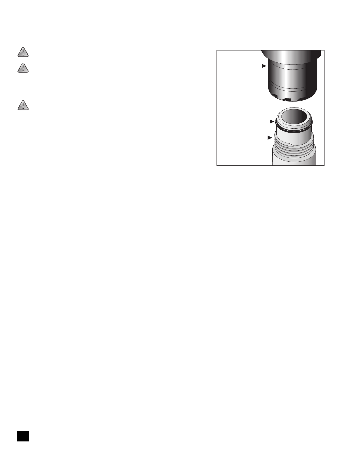
Note the correct and incorrect
swing-joint installation method.
1
ACME read Notes
!
!
!
e ACME thread golf sprinkler body requires an ACME thread swing joint for connection to the piping system. e ACME
swing joint has an o-ring on the exit tting that provides a water-tight seal inside the sprinkler body when properly assembled.
CAUTION: With the ACME tting, do not use thread sealants such as
Teon™ tape or pipe dope.
Important! For ease of assembly and to ensure proper sealing, moisten the
o-ring with clean water just prior to installation.
To Install Sprinklers:
Screw the sprinkler body clockwise onto the ACME swing joint exit tting until
it stops. No further adjustment is required.
CAUTION: Leakage between the swing joint exit tting and the
sprinkler body may indicate that the o-ring is improperly seated, missing,
damaged and/or the sprinkler body is not completely installed.
If leakage is observed, perform the following procedure:
1. Shut o and relieve system water pressure.
2. Remove the sprinkler from the swing joint tting.
3. Verify that the o-ring is undamaged and is properly seated in the o-ring
groove. (Replace the o-ring if necessary.)
Moisten the o-ring with water, reinstall the sprinkler, repressurize the system
and check for leakage.
Sprinkler Body
O-Ring
ACME Thread
Swing Joint
Exit Fitting
2
Unpacking the Sprinkler
!
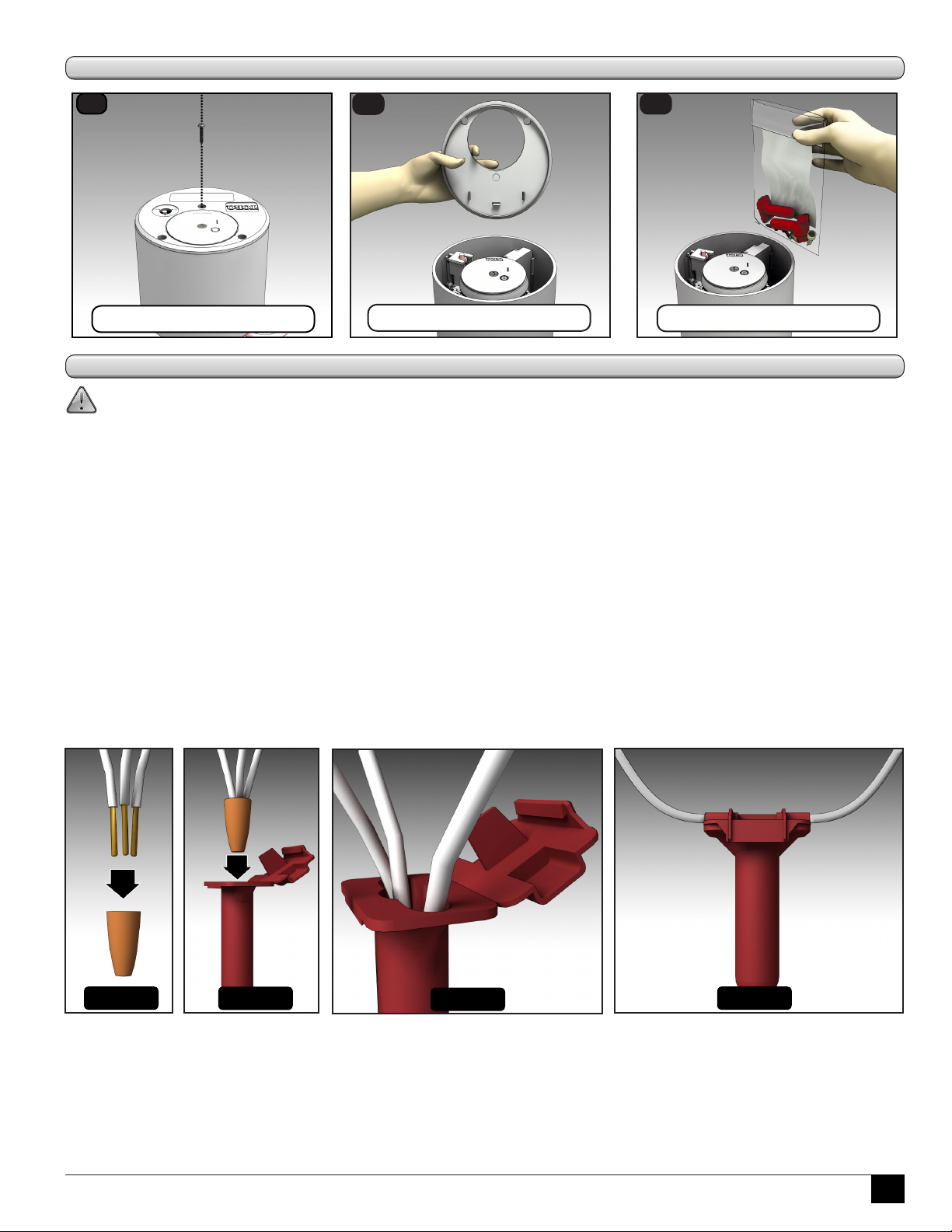
1
Remove the retaining screw.
2
Lift the cover.
3
Remove accessory kit.
Waterproof Wire Splices
CAUTION: All wire splices and eld connections must be waterproofed to prevent short circuit to ground and
subsequent controller damage.
is type of waterproofed wire splice is for use with solid and/or stranded wire connections.
1 - 3 #12
2 - 5 #18
2 #12 w/ 1 or 2 #18
Steps
1 - 4 #14
1 #10 w/ 1-4 #18
1 #14 w/ 1-4 #18
2 - 5 #16
1 #12 w/ 1-4 #18
3 #14 w/ 1 or 2 #18
1. Strip wires (12-16 gauge) 7/16” (11 mm)
2. Pre-twisting is unneccessary. Hold stripped wires together with ends even (Figure 1). Lead stranded wires slightly.
Align any frayed strands or conductors.
3. Firmly push wire into connector and screw connector clockwise onto wire until tight (Figure 1).
4. Insert the splice to the bottom of the sealant lled tube (Figure 2).
5. Position wires into wire channels (Figure 3). Wipe away any sealant around opening and conductors.
6. Close lid ensuring latch is secured (Figure 4).
Figure 1
Figure 2
Figure 3
Figure 4
3
Sprinkler Wiring Connections
Connecting Communication Cable to the INFINITY Series with GDC Module
e GDC system provides a coded DC signal over a polarity sensitive color coded communication cable that requires correct
connections to ensure proper operation. e GDC system also employs a daisy chain communication network where all
sprinklers, except the last one on a wire run, will have one cable coming in from the Gateway or closer sprinkler and another
going out to the next sprinkler.
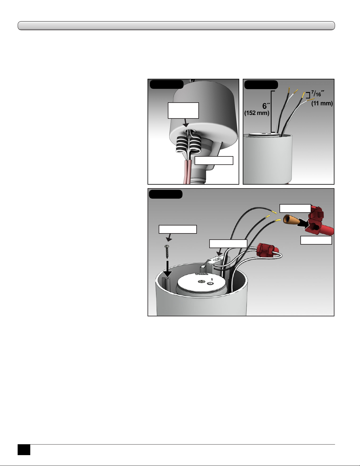
1. If using jacketed cable, remove ~20” (508
mm) of shielding from communication
cable(s).
2. Route wires through the access grommet in
the bottom of the sprinkler compartment.
Provide a service loop below the sprinkler
to allow for height adjustment and future
servicing. (See Figure 1.)
3. Pull cable(s) out the top of the sprinkler
approximately 6˝ (152 mm). (See Figure 2.)
4. Strip 12-16 gauge wires 7/16˝ (11 mm) of
insulation. (See Figure 2.)
5. Connect the white cable wire(s) and the white
GDC module wire with a wire nut and install
into a waterproof grease cap (both provided).
(See Figure 3.)
6. Repeat for the black wire(s). (See Figure 3.)
7. Fold and tuck the cable connections into the
compartment pocket.
8. Record GDC module address and reference to
site location. Remove the 2 additional address
labels from the accessory kit. Ax one to the
cover for temporary future reference and the
other to the location identication form for
entry at the central controller.
9. Replace cover and install the three (3) cover
screws (from accessory kit). Tighten to 25
in/lb. (34,6 kilogram force meters) max or
medium torque and low speed setting on a
battery-powered screw-driver.
Figure 1
access
grommet
Figure 3
spare screw
service loops
address label
Figure 2
wire nut
grease cap
4
Connecting Control Wires to the INFINITY Series with Satellite
e eld satellite controllers provide a 24 VAC
signal to the sprinklers typically using individual
wires. Connections to the sprinkler solenoid in
these systems are not polarity sensitive and do
not require specic wire connections. Typically
the “common” wire from the controller is daisychained to multiple sprinklers with one wire
coming in from the satellite or closer sprinkler
and the other going on to the next sprinkler. e
station output “hot” wire typically connects to a
single sprinkler but can also be daisy-chained to
multiple sprinklers depending upon the control
system capabilities.
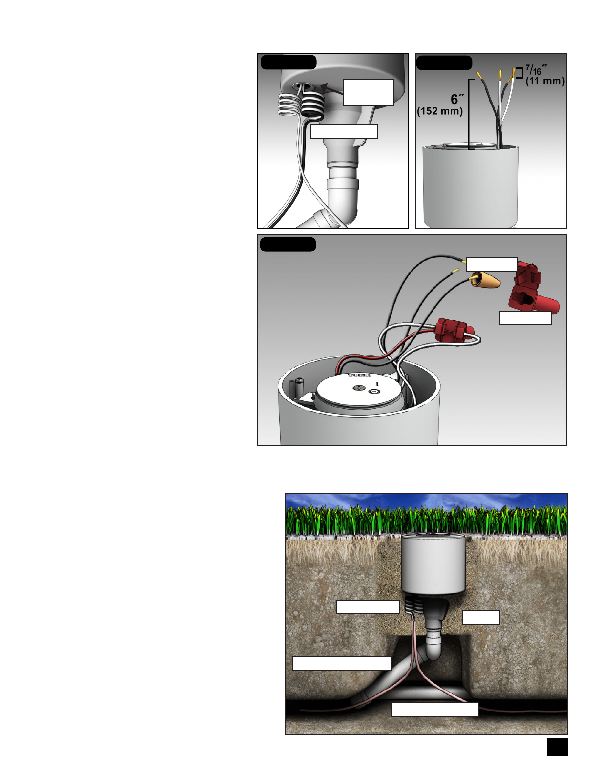
1. Route all wire(s) through the access grommet
in the bottom of the sprinkler compartment
providing a service loop below the sprinkler
to allow for height adjustment and future
servicing. (See Figure 1.)
2. Pull all wire(s) out the top of the sprinkler
approximately 6˝ (152 mm). (See Figure 2.)
3. Remove 7/16˝ (11 mm) of the insulation from
all of the control wires. (See Figure 2.)
4. Connect the “common” wire(s) to one of the
solenoid wires with a wire nut and install into
a waterproof grease cap (both provided).
(See Figure 3.)
5. Repeat for the station output “hot” wire(s).
(See Figure 3.)
6. Fold and tuck the wire connections into the
compartment pocket.
7. Replace cover and install the three (3) cover
screws (from accessory kit). Tighten to 25 in/
lb. (34,6 kilogram force meters) max or
medium torque setting on a battery-powered drill.
Figure 1
service loops
Figure 3
Figure 2
access
grommet
wire nut
grease cap
Final Adjustments
Adjust the swing joint to bring the top of the sprinkler
ush to grade. Back ll with clean porous material that
promotes drainage. Tamp the soil around the sprinkler to
compact the soil and prevent settling.
service loops
sand
Toro swing joint
mainline/lateral
5
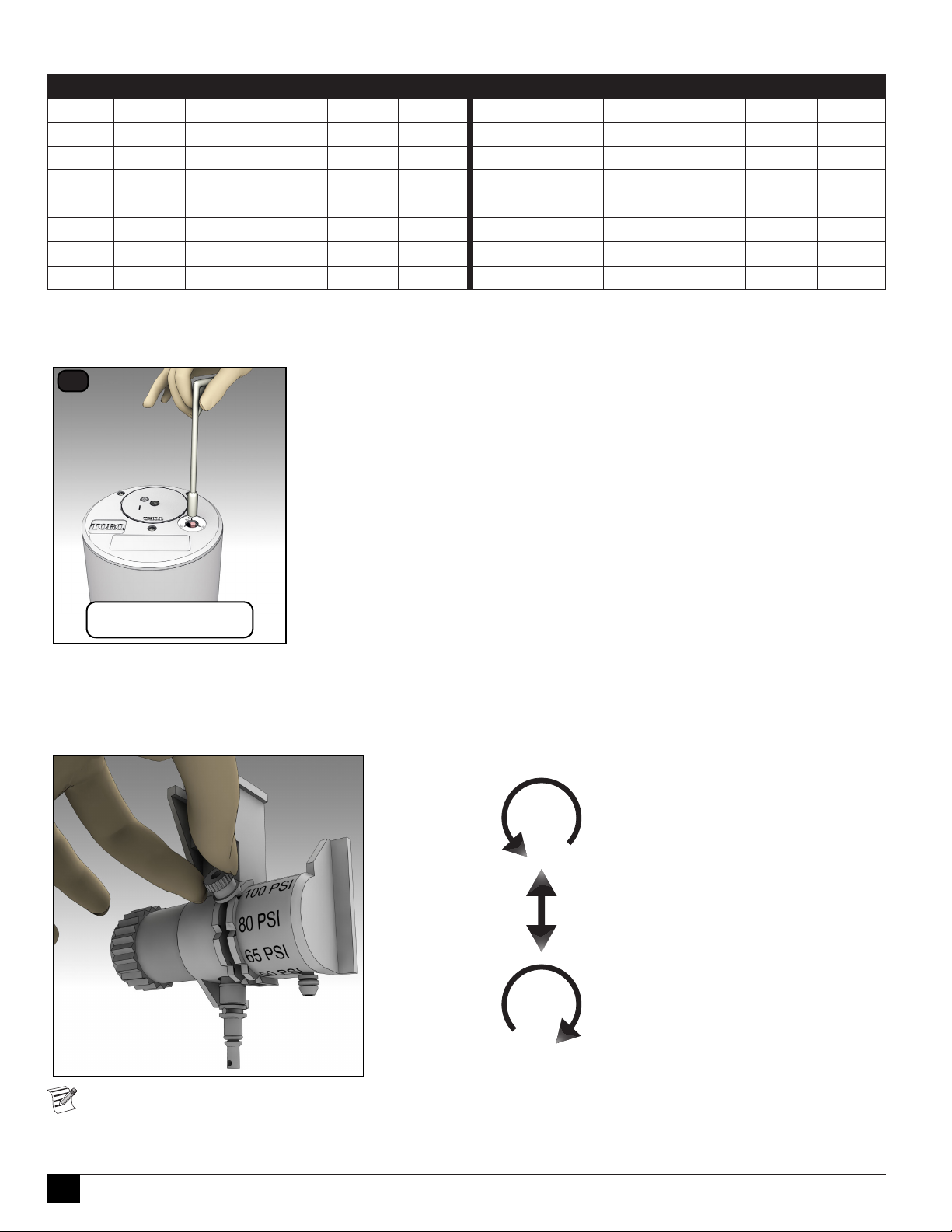
Table 1: Recommended System Fill Rate
Pipe Size Flow Velocity Pipe Size Flow Velocity
inch cm GPM LPM ft/sec m/sec inch cm GPM LPM ft/sec m/sec
1/2 1.3 2 7.6 1.60 0.49 3 7.6 45 170.3 1.86 0.57
3/4 1.9 3 11.4 1.92 0.59 4 10.1 75 283.9 1.87 0.57
1 2.5 5 18.9 1.50 0.46 6 15.2 150 567.8 1.73 0.53
1-1/4 3.1 10 37.9 1.86 0.57 8 20.2 250 946.3 1.70 0.52
1-1/2 3.8 10 37.9 1.41 0.43 10 25.4 450 1703.0 1.97 0.60
2 5.0 20 75.7 1.80 0.55 12 30.5 500 1893.0 1.55 0.47
2-1/2 6.4 30 113.6 1.84 0.56
On - O - Auto
For normal operation, the Selector should be set to AUTO.
1
ON Sprinkler will operate immediately.
OFF Sprinkler will not operate even when solenoid is activated.
AUTO Normal operation. Sprinkler will operate when solenoid is activated
according to the irrigation schedule.
Turn Selector to
appropriate setting.
Changing the Sprinkler’s Pressure Setting
e sprinkler pilot valve can be set to four dierent pressure settings: 50, 65, 80, or 100 psi (3,5, 4,6, 5,6, or 7,0, kg/cm2
respectively). e sprinkler pilot valve pressure is preset to the customer’s specications.
To change the setting:
1. Loosen adjustment knob.
To Remove Pilot Valve Assembly, follow steps on page 9.
6
2. Move knob to desired pressure setting.
3. Tighten adjustment knob.
Service
e INFINITY Series sprinklers are designed to provide the user trouble-free operation for many years without scheduled
maintenance. If it becomes necessary to disassemble the sprinkler to correct a malfunction or replace a component, all internal
parts of the sprinkler can be accessed from the top. Some special tools are required for disassembly and/or maintenance of the
sprinkler and are available from your Toro dealer.
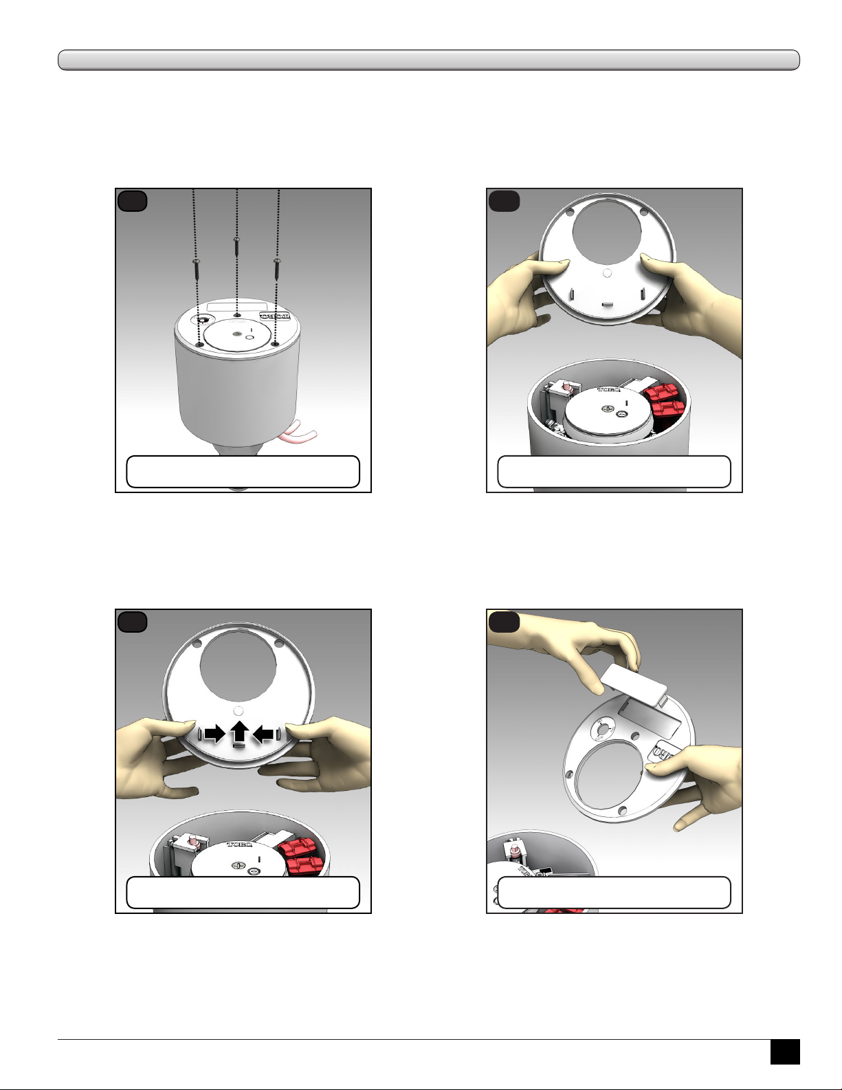
To Remove the Lid
1
Remove the top three (3) screws.
2
Lift the cover.
To Remove the Marker
Every Toro INFINITY Series Sprinkler comes with a removable identication “marker”. is marker can be customized with
yardage numbers, company logos, and more. Contact your Toro distributor for information regarding markings.
1
Push the three marker tabs inward.
2
Separate from cover.
7

To Service the GDC Module
!
e GDC module has wires running directly to the solenoid. Replacement requires cutting and splicing wires.
Use water-proof wire splices to make all connections (see page 3).
1
Slide out Module.
Cut red and black Solenoid wires.
4
2
Cut black and white Control wires.
Dispose of old Module.
5
3
Strip 7/16” (11 mm) wire from
Solenoid and Control wire endings.
6
Get new Module*, 4 wire nuts,
and 4 grease caps.
7
Put Module and all wiring carefully
back into sprinkler body.
Module wires are in pairs.
Black to black and
red with white stripe to same.
Black and white attach to black and
white Control wires.
Insert all wire ends into wire nuts.
8
Replace the cover and
secure all 3 screws to
25 inch/pounds of torque.
Insert all wire nuts into
grease caps and snap closed.
* Remember to record new
Module address for re-entry at
the Central Controller!
Operating the INFINITY™
sprinkler without the cover or
with loose or missing cover
screws may shorten the expected
service life of the sprinkler.
8
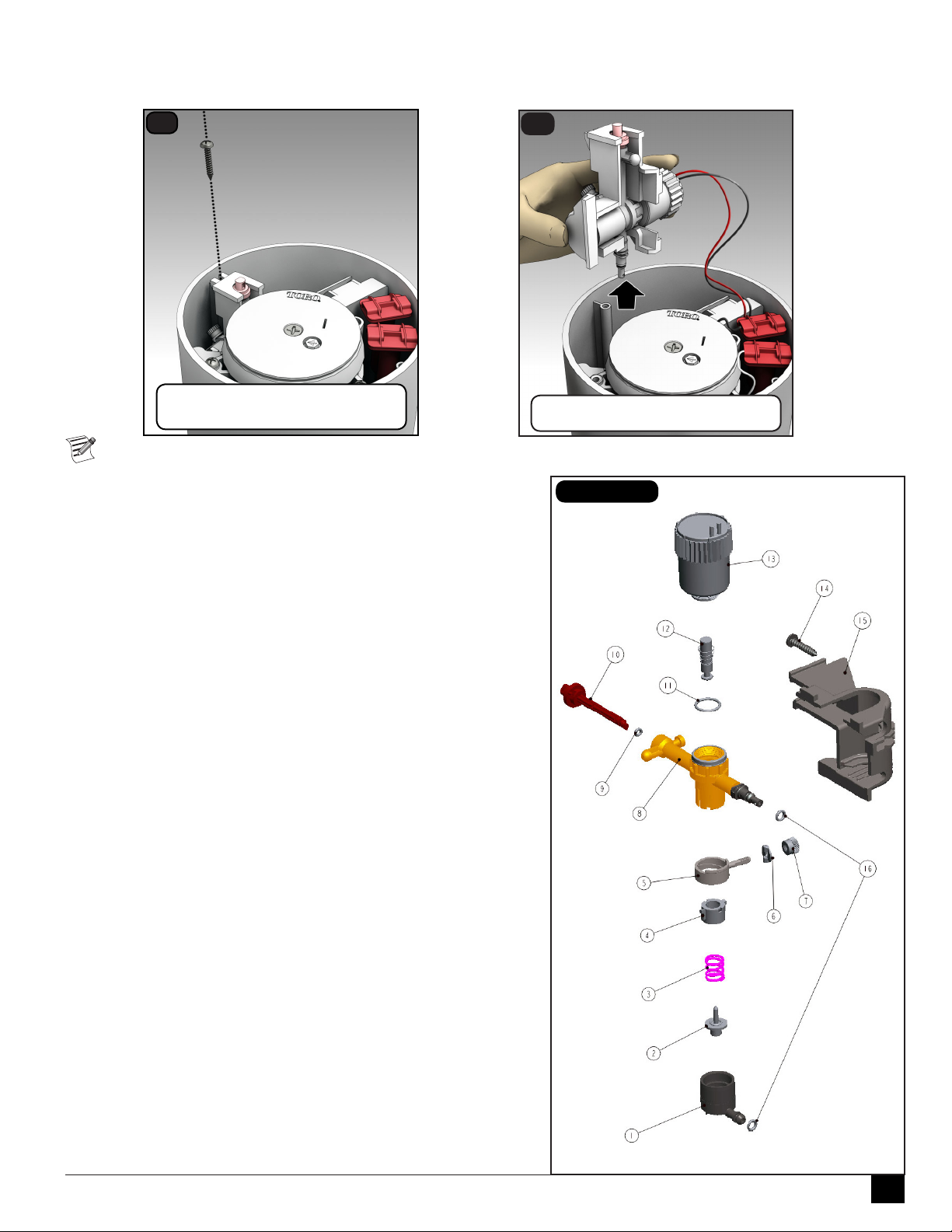
To Service the Pilot Valve
e pilot valve can be replaced while the system is under pressure. Remove the pilot valve for service.
1
Remove screw securing
pilot valve assembly.
Refer to Figure 1 for pilot valve service issues.
1. Unthread solenoid (17), unthread thumbnut (7), and remove
locator (6).
2. Remove diaphragm assembly (1), piston (2), spring (3), traveling
adjuster (4), pressure adjuster (5) and o-ring (11).
3. Remove selector shaft (10) and plunger assembly (12). (e selector
shaft retains the plunger in the valve body.)
2
Carefully slide assembly out.
Figure 1
4. oroughly clean and inspect all parts. Ensure threads are clean on
solenoid and PV body prior to assembly. Replace damaged parts
as necessary and reassemble in reverse order. Improper solenoid
assembly or cross-threading may result in damage to PV body and/or
malfunctions.
Pilot Valve Parts Breakout
1. 118-1825 Diaphragm, Welded
2. 102-2469 Piston, PV, adjustable
3. 102-2235 Spring, adjustable PV
4. 102-2236 Nut, traveling
5. 102-2237 Adjuster, PV
6. 102-2606 Locator, Pressure Setting
7. 343-4441 Nut, umb
8. 118-3711 PV, Body, Innity
9. 1-2035 O-ring
10. 102-4831 Selector, PV, red (included item 9)
11. 360-0220 O-ring
12. 118-1740 Plunger
13. 118-0248 Solenoid, Standard
13. 102-3443 Solenoid, SPIKE GUARD
13. 102-3444 Solenoid, Nickel plated, SPIKE GUARD
13. 102-2709 Solenoid, DC Latching
13. 118-0841 GDC Module w/ DC Latching Solenoid
14. 4102001 Screw, #10 x 1”, Tapping, SS
15. 118-1816 Housing, Pilot Valve
16. 2-9654 O-ring
9

To Replace the Pilot Valve Solenoid
ere are two Step 1s, depending on which version of the INFINITY Series sprinkler is being serviced.
1
With Intelligence Module:
Cut solenoid red with white stripe
and black wires.
3
1
Without Intelligence Module:
Cut black and white Control wires.
4
2
Unscrew old solenoid and dispose.
Flush plunger area with clean
water. Screw on new solenoid.
5
Strip 7/16” (11 mm) wire
from each ending.
6
Put pilot assembly and wiring
carefully back into sprinkler body
and secure with screw.
Solenoid to Intelligence Module:
twist red-to-red and black-to-black.
Solenoid to Satellite Control wires:
Match wire colors with previous
installation.
Insert all ends into wire nuts.
Insert all wire nuts into
grease caps and snap closed.
10
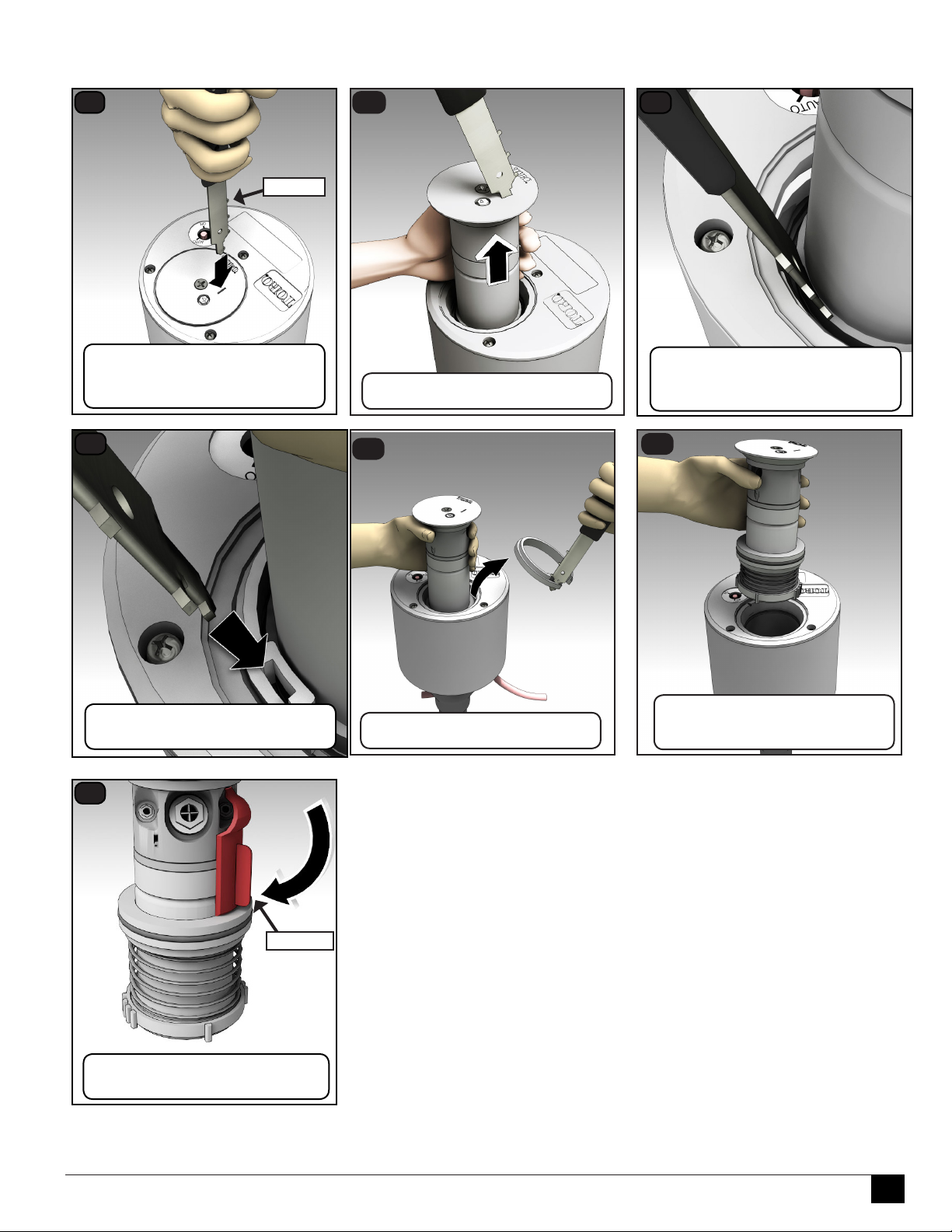
To Remove the Sprinkler Riser Assembly
1
Insert the multipurpose tool
into slot of riser cap.
Tilt tool back to lock it in.
4
995-83
2
Pull up riser and grasp rmly.
5
3
With multipurpose tool,
push seal retainer down hard to
release snap ring.
6
Insert multipurpose tool
into snap ring slot.
7
118-0954
Insert the “hold up” tool into nozzle
notch and riser spring collar.
Twist and remove snap ring.
Carefully remove the riser
assembly. The spring will push
against your hand.
11

For INF34 and INF54 Sprinklers (Full Circle only)
!
2
13
15
16
17
1
3
4
5
6
12
14
8
10
11
9
7
Refer to Figure 8 for the following procedure.
1. Grasp return spring (14) and riser (16) rmly and hold in place
while removing nozzle base (4). Turn nozzle base assembly
counter-clockwise to remove.
2. Carefully release tension from return spring.
3. Remove spring and seal retainer/o-ring assembly (12 and 13).
4. Remove riser screen (19) by turning it counterclockwise with edge
of multi-purpose tool (P/N 995-83) or tips of snap ring pliers
(P/N 995-100).
5. Remove o-ring (15) from top of riser assembly.
Figure 8
15
16
2
1
3
5
6
4
7
8
10
9
7
11
6. Remove drive assembly (17) and stator (18) from riser assembly
by carefully pressing on end of threaded shaft.
7. Using a 5/8” nut driver (P/N 995-99), unscrew main nozzle
(10) from nozzle housing (8). e riser cap (3) must still be
attached to the nozzle base assembly (4), or the nozzle housing
(8) will turn instead of the main nozzle.
8. Using a 5/16” nut driver (P/N 995-105), unscrew intermediate
nozzle (6) and inner nozzle (5) and plugs (7) from the nozzle
base assembly.
9. oroughly clean and inspect all parts and replace as necessary.
During reassembly, ensure snap ring is correctly installed and
fully seated in snap ring groove. Use the Multipurpose tool to
assist in proper placement.
For INF35 and INF55 Sprinklers (Full/Partial Circle)
Refer to Figure 9 for the following procedure.
1. Remove riser screen (17) by turning it counterclockwise
with edge of multi-purpose tool (P/N 995-83) or tips of
snap ring pliers (P/N 995-100).
2. Remove the variable stator (16) from riser assembly.
3. Loosen the drive assembly retaining screw (14) six or
seven turns and pull the drive assembly (15) using a pair
of pliers.
CAUTION: When removing or installing the drive
assembly, do not use the turbine to pull the drive
assembly. Use the drive assembly body to extract it out.
Failure to comply may cause separation of the drive
assembly components.
17
18
19
Figure 9
12
13
14
During reassembly, ensure drive assembly is properly
aligned with the retaining screw.
4. Using a 5/8” nut driver (P/N 995-99), unscrew main
nozzle (9) from nozzle base assembly.
5. Using a 5/16” nut driver (P/N 995-105), unscrew the
inner (8), intermediate (7) nozzles, and plug (12).
6. oroughly clean and inspect all parts and replace as
necessary.
12

To Install the INF35 and INF55 Sprinkler Riser Assemblies
1
Insert the “hold up” tool into nozzle
notch and riser spring collar.
4
2
Note locations of alignment
notch and rib.
5
3
Center the ratchet ring on the
alignment notch and insert riser.
6
Press retainer / o-ring assembly
down below snap ring groove.
Put snap ring, stepped side up,
around riser body.
Push snap ring down
until it “snaps” into place.
The multipurpose tool can help.
Remove “hold up” tool and lower
riser to retracted position.
To Install the INF34 and INF54 Sprinkler Riser Assembly
To install the INF34 and/or the INF54, follow the steps above except for the steps 2 and 3; those are not necessary.
13
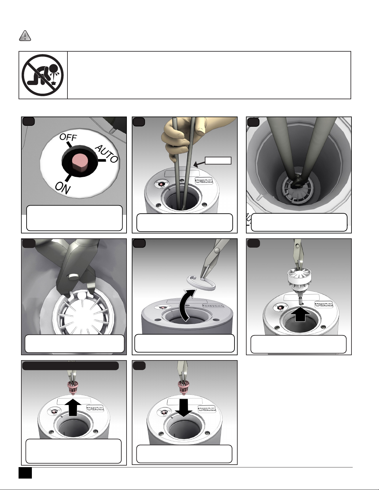
To Service the Main Valve and Rock Screen
!
WARNING: To service the main valve, the water supply to sprinkler must be shut o and any residual water bled
o.
WARNING
NEVER STAND OR LEAN OVER THE SPRINKLER WHILE THE IRRIGATION SYSTEM IS
BEING FILLED, DURING MANUAL OR AUTOMATIC OPERATION, OR WHEN PERFORMING
SPRINKLER SERVICE PROCEDURES. DIRECT CONTACT WITH IRRIGATION SPRAY, A FAILED
OR IMPROPERLY INSTALLED SPRINKLER CONNECTION, OR SPRINKLER COMPONENTS
FORCIBLY EJECTED UPWARD UNDER PRESSURE CAN CAUSE SERIOUS INJURY.
e riser assembly must be removed from the sprinkler body to service the main valve. See page 11 to remove riser assembly.
1
Place the manual selector
into the ON position to ensure
water is off and pressure relieved.
4
2
You will need long pliers
(part number 995-100).
5
3
995-100
Use long pliers to push down on
center of valve cylinder.
6
Then grasp snap ring at “hooks”
and squeeze together.
7 - Service the Rock Screen
Using the pliers,
remove the rock screen.
Clean or replace as necessary.
Grab the hook that is furthest out
and pull up while twisting.
8
Using the pliers, press the rock
screen back into position.
Using the pliers,
remove main valve assembly.
14

To Reinstall Main Valve
Use the valve insertion tool. ere are two sizes of the tool depending on the size of the sprinkler inlet.
• 118-1843 is the 1.5” (40 mm) valve insertion tool
• 118-1844 is the 1” (25 mm) valve insertion tool
1
Load snap ring onto insertion tool.
Trigger is in “down” position.
4
2
“Step” side of ring faces up.
Ring “hooks” are hooked
around insertion tool prongs.
5
3
Align valve communication port
with notch on insertion tool.
Load valve assembly onto tool.
6
Push tool down completely then pull
Insert valve assembly.
7
Remove tool.
Align the tool handle, the snap ring,
and the valve with the notch in body.
8
Replace riser assembly.
(See page 13 for full procedure.)
up on “trigger” to release the snap
ring.
e snap ring will “snap!” into groove when properly installed. Remove insertion tool and check snap ring to conrm
that it is fully seated in groove.
15

Flushing the Sprinkler
1. With sprinkler operating, carefully step down on center of cap several times. Water will ow around riser and ush out debris.
2. Cycle sprinkler on and o several times to check for proper retraction. Cap should be even with top of body ange when fully retracted. If
riser sticks in up position, check for debris lodged between riser and body. Flush out all debris. Remove riser assembly if necessary.
Troubleshooting Guide
Problem Cause Solution
Sprinkler will not turn on.
Sprinkler will not shut o.
Sprinkler will not rotate.
Head sticks up
Poor distribution pattern
No 24 VAC to solenoid assembly.
Debris in pilot valve assembly.
Selector cam in “OFF” position.
Pilot valve solenoid inoperative.
Pilot valve plunger movement restricted.
No water supply from main valve.
Constant 24 VAC from controller
Selector cam in “ON” position.
Debris in pilot valve assembly.
Leak in pilot valve assembly.
Plugged supply screen on piston.
Plunger movement restricted.
Valve cylinder misaligned with sprinkler
body communication tube.
Foreign object keeping valve from seating.
Damaged piston seal or piston assembly.
Debris wedged between stator and turbine.
Drive assembly defective.
Nozzle base assembly defective.
Dirt in riser assembly.
Damaged or missing return spring.
Damaged riser.
Nozzle plugged with debris.
Nozzle orice damaged.
Low operating pressure.
Measure voltage with a Digital Volt Meter.
Check wiring and controller program.
Disassemble and remove all debris.
(See Servicing Pilot Valve, page 9.)
Set to “AUTO” position.
Remove and replace solenoid.
Inspect, clean, and/or replace.
Debris in control tube, main valve assembly, and/or
communication passages in body. Flush thoroughly.
Check for voltage using a DVM. If voltage is present,
disconnect wire. If sprinkler closes, service controller.
Refer to Controller Service Manual.
Set to “OFF” position.
Disassemble and remove all debris.
(See Servicing Pilot Valve, page 14.)
Replace pilot valve assembly.
Clean or replace screen on main valve piston.
Inspect and clean or replace.
Remove valve assembly and install correctly.
Remove, clean, and check for valve damage.
Replace if necessary.
Replace valve assembly.
Remove obstruction.
Replace drive assembly.
Replace nozzle base assembly.
Flush out. (See top of this page.)
Replace spring.
Replace riser.
Clean or replace nozzle.
Replace nozzle.
Determine why system is overloaded and correct.
Toro Warranty and Support
e Toro Company and its aliate, Toro Warranty Company, pursuant to an agreement between them, jointly warrants, to the owner, against defects in
material and workmanship for a period of three years from the date of purchase. (Five years if Toro Swing Joint installed with sprinkler.) Neither e Toro
Company nor Toro Warranty Company is liable for failure of products not manufactured by them, even though such products may be sold or used in
conjunction with Toro products.During such warranty period, we will repair or replace, at our option, any part found to be defective. Return the defective
part to the place of purchase. Our liability is limited solely to the replacement or repair of defective parts. ere are no other express warranties. is
warranty does not apply where equipment is used, or installation is performed, in any manner contrary to Toro’s specications and instructions, nor where
equipment is altered or modied. Neither e Toro Company nor Toro Warranty Company is liable for indirect, incidental or consequential damages in
connection with the use of equipment, including but not limited to: vegetation loss, the cost of substitute equipment or services required during periods of
malfunction or resulting non-use, property damage or personal injury resulting from installer’s negligence.
Some states do not allow the exclusion or limitation of incidental or consequential damages, so the above limitation or exclusion may not apply to you.
All implied warranties, including those of merchantability and tness for use, are limited to the duration of this express warranty. Some states do not allow
limitations of how long an implied warranty lasts, so the above limitation may not apply to you. is warranty gives you specic legal rights and you may
have other rights which vary from state to state.
© 2014 The Toro Company, Golf Division • www.toro.com • 1-877-345-8676 Form Number 373-0798 Rev. B
16
 Loading...