

Page 1

HydroJect) 3010
Aerator
Model No. 09802—250000001 and Up
Form No. 3356–184 Rev B
Operator’s Manual
Domestic English (EN)
Page 2

Warning
The engine exhaust from this product contains
chemicals known to the State of California to cause
cancer, birth defects, or other reproductive harm.
This spark ignition system complies with Canadian
ICES-002.
Ce système d’allumage par étincelle de véhicule est
conforme à la norme NMB-002 du Canada.
Contents
Introduction 3. . . . . . . . . . . . . . . . . . . . . . . . . . . . . . . . .
Safety 3. . . . . . . . . . . . . . . . . . . . . . . . . . . . . . . . . . . . . .
Safe Operating Practices 3. . . . . . . . . . . . . . . . . . . .
Sound Pressure Level 5. . . . . . . . . . . . . . . . . . . . . . .
Sound Power Level 5. . . . . . . . . . . . . . . . . . . . . . . .
Vibration Level 5. . . . . . . . . . . . . . . . . . . . . . . . . . . .
Safety and Instruction Decals 5. . . . . . . . . . . . . . . . .
Specifications 9. . . . . . . . . . . . . . . . . . . . . . . . . . . . . . . .
General Specifications 9. . . . . . . . . . . . . . . . . . . . .
Controls 9. . . . . . . . . . . . . . . . . . . . . . . . . . . . . . . . .
Water Injection System 10. . . . . . . . . . . . . . . . . . . . .
Dimensions 10. . . . . . . . . . . . . . . . . . . . . . . . . . . . . . .
Depths and Nozzle Configurations 11. . . . . . . . . . . .
Setup 12. . . . . . . . . . . . . . . . . . . . . . . . . . . . . . . . . . . . . .
Loose Parts 12. . . . . . . . . . . . . . . . . . . . . . . . . . . . . . .
Installing the Rear Wheels 12. . . . . . . . . . . . . . . . . . .
Before Operating 13. . . . . . . . . . . . . . . . . . . . . . . . . . . . .
Activating and Charging the Battery 13. . . . . . . . . . .
Checking the Engine Oil 14. . . . . . . . . . . . . . . . . . . .
Filling the Gas Tank 14. . . . . . . . . . . . . . . . . . . . . . . .
Checking the Gear Case Fluid Level 15. . . . . . . . . . .
Checking the Pump Case Fluid Level 16. . . . . . . . . .
Checking the Tire Pressure 16. . . . . . . . . . . . . . . . . .
Checking the Accumulator Charge 16. . . . . . . . . . . .
Operation 17. . . . . . . . . . . . . . . . . . . . . . . . . . . . . . . . . . .
Controls 17. . . . . . . . . . . . . . . . . . . . . . . . . . . . . . . . .
Operating Precautions 18. . . . . . . . . . . . . . . . . . . . . .
Starting and Stopping the Engine 18. . . . . . . . . . . . . .
Training Period 19. . . . . . . . . . . . . . . . . . . . . . . . . . . .
Water Supply 19. . . . . . . . . . . . . . . . . . . . . . . . . . . . .
Operating Procedure 19. . . . . . . . . . . . . . . . . . . . . . .
Checking the Interlock System 20. . . . . . . . . . . . . . .
Transport Operation 21. . . . . . . . . . . . . . . . . . . . . . . .
Inspection and Clean-Up After Use 21. . . . . . . . . . . .
Pushing or Towing the Machine 21. . . . . . . . . . . . . .
W 2005 by The Toro Company
8111 Lyndale Avenue South
Bloomington, MN 55420-1196
Page
Maintenance 23. . . . . . . . . . . . . . . . . . . . . . . . . . . . . . . . .
Recommended Maintenance Schedule 23. . . . . . . . .
Daily Maintenance Checklist 24. . . . . . . . . . . . . . . . .
Lubricating the Machine 25. . . . . . . . . . . . . . . . . . . .
Servicing the Pre-Filter 26. . . . . . . . . . . . . . . . . . . . .
Replacing the Main Water Filter 26. . . . . . . . . . . . . .
Changing the Engine Oil and Filter 27. . . . . . . . . . . .
General Air Cleaner Maintenance 27. . . . . . . . . . . . .
Servicing the Air Cleaner 27. . . . . . . . . . . . . . . . . . . .
Checking and Replacing the Spark Plugs 28. . . . . . .
Changing the Gear Case Oil and Filter 29. . . . . . . . .
Changing the Pump Case Oil 30. . . . . . . . . . . . . . . . .
Checking the Hydraulic Lines and Hoses 30. . . . . . .
Adjusting the Traction Pump Belt 30. . . . . . . . . . . . .
Adjusting the Transmission for Neutral 31. . . . . . . . .
Adjusting the Aeration Speed 31. . . . . . . . . . . . . . . .
Adjusting the Parking Brake 32. . . . . . . . . . . . . . . . .
Adjusting the Roller Spray Wash System 32. . . . . . .
Servicing the Spray Wash Nozzles or Strainers 33. . .
Caring for the Battery 33. . . . . . . . . . . . . . . . . . . . . .
Seasonal Storage 34. . . . . . . . . . . . . . . . . . . . . . . . . . . . .
Preparing the Water System 34. . . . . . . . . . . . . . . . . .
Preparing the Engine 34. . . . . . . . . . . . . . . . . . . . . . .
Preparing the Traction Unit 34. . . . . . . . . . . . . . . . . .
Troubleshooting 35. . . . . . . . . . . . . . . . . . . . . . . . . . . . . .
Hydraulic Schematic 39. . . . . . . . . . . . . . . . . . . . . . .
Electrical Schematic 40. . . . . . . . . . . . . . . . . . . . . . . .
Electrical Schematic 41. . . . . . . . . . . . . . . . . . . . . . . .
Water System Schematic 42. . . . . . . . . . . . . . . . . . . .
The Toro Aerator Commercial Products Warranty 44. . .
All Rights Reserved
Printed in the USA
2
Page 3

Introduction
Read this manual carefully to learn how to operate and
maintain your product properly. The information in this
manual can help you and others avoid injury and product
damage. Although Toro designs and produces safe
products, you are responsible for operating the product
properly and safely.
Whenever you need service, genuine Toro parts, or
additional information, contact an Authorized Service
Dealer or Toro Customer Service and have the model and
serial numbers of your product ready. The model and serial
numbers are stamped on a plate which is riveted to the
frame.
Write the product model and serial numbers in the space
below:
Model No.
Serial No.
Safe Operating Practices
The following instructions are from ANSI standard
B71.4—2004.
Training
• Read the Operator’s Manual and other training material.
If the operator(s) or mechanic(s) can not read English it
is the owner’s responsibility to explain this material to
them.
• Become familiar with the safe operation of the
equipment, operator controls, and safety signs.
• All operators and mechanics should be trained. The
owner is responsible for training the users.
• Never let children or untrained people operate or
service the equipment. Local regulations may restrict
the age of the operator.
• The owner/user can prevent and is responsible for
accidents or injuries occurring to himself or herself,
other people or property.
This manual identifies potential hazards and has special
safety messages that help you and others avoid personal
injury and even death. Danger, Warning, and Caution are
signal words used to identify the level of hazard. However,
regardless of the hazard, be extremely careful.
Danger signals an extreme hazard that will cause serious
injury or death if you do not follow the recommended
precautions.
Warning signals a hazard that may cause serious injury or
death if you do not follow the recommended precautions.
Caution signals a hazard that may cause minor or moderate
injury if you do not follow the recommended precautions.
This manual uses two other words to highlight information.
Important calls attention to special mechanical
information and Note: emphasizes general information
worthy of special attention.
Safety
Improper use or maintenance by the operator or owner
can result in injury. To reduce the potential for injury,
comply with these safety instructions and always pay
attention to the safety alert
CAUTION, WARNING, or DANGER—“personal
safety instruction.” Failure to comply with the
instruction may result in personal injury or death.
symbol, which means
Preparation
• Evaluate the terrain to determine what accessories and
attachments are needed to properly and safely perform
the job. Only use accessories and attachments approved
by the manufacturer.
• Wear appropriate clothing including hard hat, safety
glasses and hearing protection. Long hair, loose
clothing or jewelry may get tangled in moving parts.
• Inspect the area where the equipment is to be used and
remove all objects such as rocks, toys and wire which
can be contacted by the aerator.
• Use extra care when handling gasoline and other fuels.
They are flammable and vapors are explosive.
• Use only an approved container
• Never remove gas cap or add fuel with engine
running. Allow engine to cool before refueling.
Do not smoke.
• Never refuel or drain the aerator indoors.
• Check that operator’s presence controls, safety switches
and shields are attached and functioning properly. Do
not operate unless they are functioning properly.
Operation
• Never run an engine in an enclosed area.
• Only operate in good light, keeping away from holes
and hidden hazards.
3
Page 4

• Be sure all drives are in neutral and parking brake is
engaged before starting engine. Start the engine only
from the operator’s position.
• Never operate without the shields, covers or other
guards securely in place. Be sure all interlocks are
functioning properly.
• Keep hands and feet away from the nozzle and roller
area. High velocity water jets can penetrate hands and
feet. Penetration by the high velocity water jets can
cause serious personal injury. If accidental penetration
occurs, seek medical attention immediately.
• Never use chemicals in the water supply system.
• Do not operate the water injection system on concrete
or asphalt because water jets will permanently damage
these surfaces.
• Before disconnecting or performing any work on the
water system, all pressure in the system must be
relieved by stopping the engine and opening the bleed
valve. Opening the bleed valve allows any trapped
water to escape from the system and also allows the
accumulator piston to move to the bottom of the
accumulator cylinder.
• Do not change the engine governor setting or overspeed
the engine.
• The accumulator in this machine contains high pressure
dry nitrogen. Accumulator servicing requires special
tools and precautions. Accumulators do not contain user
serviceable components. Improper accumulator
servicing can cause dismemberment or death. Do not
attempt to disassemble an accumulator; have this work
done by an Authorized Toro Distributor.
• Stop on level ground, disengage drives, engage parking
brake, shut off engine before leaving the operator’s
position for any reason.
• Never carry passengers and keep pets and bystanders
away.
• Be alert, slow down and use caution when making
turns. Look behind and to the side before changing
directions.
• Slow down and use caution when crossing roads and
sidewalks.
• Do not operate the aerator under the influence of
alcohol or drugs.
• Use extreme care when loading or unloading the aerator
into a trailer or truck.
• Use care when approaching blind corners, shrubs, trees,
or other objects that may obscure vision.
Slope Operation
• Do not operate near drop–offs, ditches, steep banks or
water. Wheels or rollers dropping over edges can cause
rollovers, which may result in serious injury or death.
• Do not operate on slopes when grass is wet. Slippery
conditions reduce traction and could cause sliding and
loss of control.
• Do not make sudden turns or rapid speed changes.
• Reduce speed and use extreme caution on slopes.
• Remove or mark obstacles such as rocks, tree limbs,
etc. from the operating area. Tall grass can hide
obstacles.
• Watch for ditches, holes, rocks, dips, and rises that
change the operating angle, as rough terrain could
overturn the aerator.
• Be aware that loss of traction may occur going
downhill. Weight transfer may cause drive wheel to slip
and cause loss of braking and steering.
• Always avoid sudden starting or stopping on a slope. If
tire loses traction, disengage the water injection system
and proceed slowly off the slope.
Maintenance and storage
Warning
Engine exhaust contains carbon monoxide, which
is an odorless, deadly poison that can kill you.
Do not run engine indoors or in an enclosed area.
• Make sure all hydraulic line connectors are tight and all
hydraulic hoses and lines are in good condition before
applying pressure to the system.
• Keep your body and hands away from pin hole leaks or
nozzles that eject hydraulic fluid under high pressure.
Use paper or cardboard, not your hands, to search for
leaks. Hydraulic fluid escaping under pressure can have
sufficient force to penetrate the skin and cause serious
injury. Seek immediate medical attention if fluid is
injected into skin.
• Before disconnecting or performing any work on the
hydraulic system, all pressure in the system must be
relieved by stopping the engine and lowering the deck
and attachments to the ground.
• Let engine cool before storing and do not store near
flame.
• Shut off fuel while storing or transporting on trailers.
Do not store fuel near flames or drain indoors.
4
Page 5
• Park machine on level, hard ground. Never allow
untrained personnel to service machine.
• Use only Toro-approved attachments. Warranty may be
voided if used with unapproved attachments.
• Use jack stands or safety latches to support components
when required.
• Carefully release pressure from components with stored
energy.
• Disconnect battery or remove spark plug wire before
making any repairs. Disconnect the negative terminal
first and the positive last. Reconnect positive first and
negative last.
• Keep hands and feet away from moving parts. If
possible, do not make adjustments with the engine
running.
• Charge batteries in an open well ventilated area, away
from spark and flames. Unplug charger before
connecting or disconnecting from battery. Wear
protective clothing and use insulated tools.
• Keep all parts in good working condition and all
hardware tightened. Replace all worn or damaged
decals.
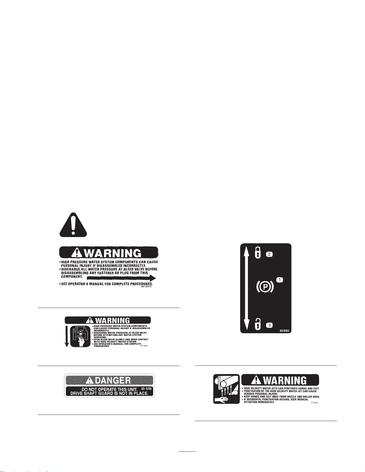
Safety and Instruction Decals
Safety decals and instructions are easily visible to the operator and are located near any area
of potential danger. Replace any decal that is damaged or lost.
Sound Pressure Level
This unit has an equivalent continuous A–weighted sound
pressure level at the operator ear of 93 dBA, based on
measurements of identical machines per Directive
98/37/EC and amendments.
Sound Power Level
This unit has a guaranteed sound power level of:
108 dBA/1 pW, based on measurements of identical
machines per Directive 2000/14/EC and amendments.
Vibration Level
This unit does not exceed a vibration level of 4.0 m/s@ at
the hands based on measurements of identical machines per
ISO 5349 procedures.
80-8000
80-8880
80-8760
1. Parking brake
2. Locked
5
93-9363
3. Unlocked
80-8090
Page 6
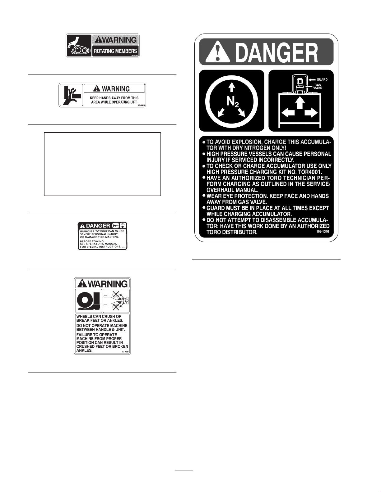
80-8040
80-8010
THE FIVE MICRON FILTER ELEMENT (86–8620) MUST
IMPORTANT
D
BE IN PLACE AT ALL TIMES.
OPERATION WITHOUT PROPER FILTRATION WILL
D
RESULT IN PREMATURE WEAR AND FAILURE OF THE
WATER SYSTEM COMPONENTS.
USE OF ADDITIONAL FILTRATION OR POTABLE WATER
D
MAY BE NECESSARY TO PROLONG THE LIFE OF THE
FILTRATION SYSTEM.
SEE OPERATOR’S MANUAL FOR MORE INFORMATION.D
92-9542
72-4080
108-1316
93-9429
6
Page 7
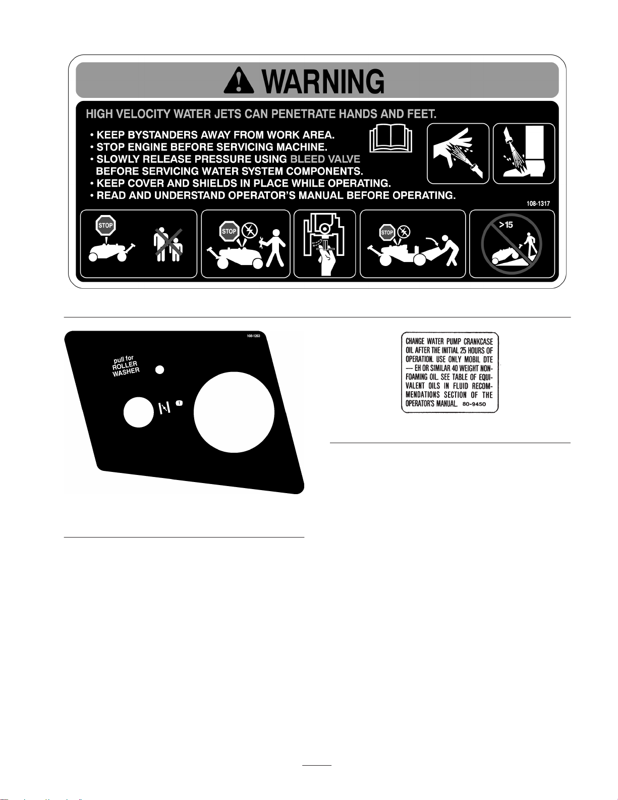
1. Choke
108-1317
80-9450
108-1263
7
Page 8
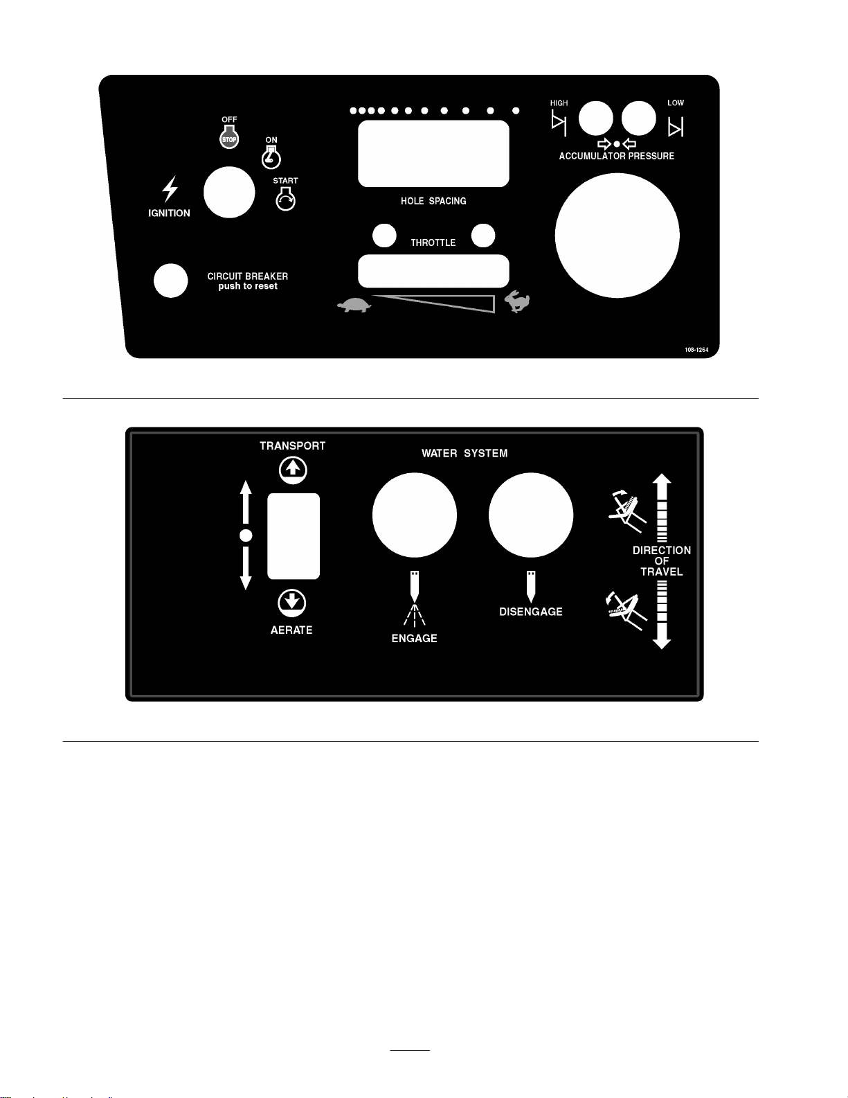
108-1264
108-1265
8
Page 9

Specifications
Note: Specifications and design subject to change without notice.
General Specifications
Kohler, 4 cycle, V–twin, air cooled, 27 hp @ 3600 RPM, 44 cu. in (725 cc)
Engine
displacement. Electric start. Heavy duty air cleaner. 2 quart oil capacity. Solid state
ignition. Meets California Exhaust Emission Standard and EPA Standards for Lawn
and Garden Equipment.
Clutches
Electrical
Traction Drive
Tires/Wheels
Brake
Transport Lift
Fuel Capacity 10.5 gallons gasoline
Ground Speed
Aeration Width 33 inches with 11 nozzles on 3 inch centers
Aeration Depth 4 to 6 inches depending on turf conditions and nozzle configuration
Hole Pattern
Electromagnetic, dual groove belt drive for water pump and drive shaft flange
brake/clutch for main valve gearbox.
12 volt system with 15 amp circuit breaker protection. Relays for all high current
switching. Electronic controller and sensors for automatic startup and shutdown
sequence of water injection system. Group 28 battery with 535 cold crank amps.
Closed loop hydrostatic drive consisting of Sundstrand variable volume pump and
Parker low speed, high torque wheel motor mounted to steering fork. Hydraulic
system contains 5 quarts with 25 micron suction line filter and gearbox reservoir.
Three, smooth tread 2 ply, 18 x 9.50-8,pneumatic tubeless, tires. De–mountable
drop center steel wheels with 4 lug nuts mounted to tapered roller bearing hubs on
transport arms and brake hub on wheel motor. All are interchangeable.
Drum and shoe-type parking brake mounted to wheel motor. Holds unit on a 30%
grade.
12 volt Warner Electric linear screw actuator with 6 inch stroke. Raises and lowers
lift arm/transport tires and activates hole spacing control.
Aerating: 0–2 MPH (both directions)
Transport: 0–4 MPH (both directions)
Variable from 1-1/2 to 6 in. spacing in the direction of travel, and 3 or 6 in.
increments in width
Controls
Engine Panel
Steering Tiller Panel
Electronic Control Module
Throttle, choke, spray wash control, hour meter, water pressure gauge, spacing
control lever, key switch, and circuit breaker reset button
Traction bail, water system engage and disengage buttons, transport/aerate lift
rocker switch, and parking brake with buzzer alarm.
Solid state potted device for sequencing start and stop of water system. Interlocks
for water pressure, transport lift, traction neutral and accumulator over–pressure.
9
Page 10

Water Injection System
Pre-Filter
Supply Filter Replaceable cartridge in plastic housing with air bleed button.
Water Pressure Switch
Pump
Accumulator
Cam and Gearbox
Valve
Rollers
Spin down type with washable cartridge in clear plastic housing and plastic ball
valve for flushing.
Senses for water pressure after filter and turns on when pressure is over 20–28 psi
and turns off when pressure drops below 7–13 psi.
Pump is a Toro exclusive design with cast stainless steel head and 3 piston
plungers. Vee packing seals and Kevlar guides. Forged crankshaft with plasma
sprayed ceramic on stainless steel plungers and cast iron connecting rods. Nominal
performance is 4 gpm @ 5000 psi with 1400 RPM input.
Toro exclusive design with high and low charge pressure sensors, nitrogen gas
charged to a maximum of 2500psi.
Reduction gear drive for cam that actuates main water valve. Roller cam follower
rides on cam specifically designed to control water injection at 5.3 cycles per
second (320 RPM) and store energy in accumulator between injections. Cast iron
case also serves as 4 quart hydraulic reservoir.
Cast stainless steel valve body functions as mounting base for accumulator,
gearbox, and manifold outlet. All high pressure water flows in and out through the
valve body. Pressure balanced valve spool with floating, hardened stainless seat
aligns during assembly. Bleed valve in base allows for bleed-off of high pressure
and drain down for cold weather storage. Bolted flanges and polyurethane o-rings
mate all components to valve body.
Pivoting aluminum rollers uniformly smooth the turf and provide protection from the
nozzle discharge. Adjustable flow (0–3 gpm) spray wash system with 6 flood tip
nozzles maintain clean rollers.
Pressure Relief Valve
Manifold and Nozzles
Circle Seal Controls poppet-type valve preset to 5000 psi with corrosion resistant
stainless and brass materials.
Extruded stainless steel manifold with 11 flanged nozzle extensions containing
check valves and hardened stainless discharge orifice. Check valves may be
reversed in housing to block unused nozzles.
Dimensions
Length 96.2 in. (244 cm)
Wheelbase 53.2 in. (135 cm)
Width 63 in. (160 cm)
Height 38.2 in. (97 cm)
Weight 1120 lb. (508 kg)
10
Page 11

Depths and Nozzle Configurations
Decimal
Metric Size
Approx
Decimal
Metric Size
Approx
All nozzles are identified with numbers indicating the drill size of the orifice. The standard configuration is 11 nozzles
producing depths of 4 to 6 inches depending on turf conditions. Blocked nozzle locations are obtained by reversing the nozzle
check valve ball and spring. See nozzle size chart and illustrations below:
Important Use only nozzle configurations shown or damage to the machine may occur.
Nozzle Size and Approximate Depth Chart
Part No. Drill Size
86-8130 #56 0.0465 1.181 * * *
86-8131 #53 0.0595 1.511 11 0 4–6 in.
86-8133 #46 0.081 2.057 6 5 6–8 in.
* Use only with varied size configurations
Note: Aluminum Washer, Toro Part no. 80-6680, is required with any nozzle change.
Optional Staggered Size Nozzle Configuration
Part No. Drill Size
86-8130 #56 0.0465 1.181 6 and 0** 3–4 in.
86-8133 #46 0.081 2.057 5 0** 6–8 in.
** Additional nozzles may be blocked to compensate for pump wear.
Note: Aluminum Washer, Toro Part no. 80-6680, is required with any nozzle change.
Decimal Metric Size
Size (inch)
Decimal Metric Size
Size (inch)
(mm)
(mm)
Quantity of Nozzles
Quantity of Nozzles
Open Blocked
Open Blocked**
Approx.
Depth
Approx.
Depth
.
.
Check Valve Ball
Spring
Open Nozzle
Spring
Check Valve Ball
Closed (Blocked) Nozzle
11
Page 12
Setup
Note: Determine the left and right sides of the machine from the normal operating position.
Loose Parts
Note: Use this chart as a checklist to ensure that all parts have been received. Without these parts, total setup cannot be
completed.
Description
Wheel
Lug nut
Ignition key 1 Use in ignition switch.
Hose adapter 1 Mount to quick coupler on side of machine.
Spanner wrench 1 Use for installation and removal of water filter.
Parts catalog 1
Operator’s manual 1 Read before operating the machine.
Qty. Use
3
Installing the rear wheels
12
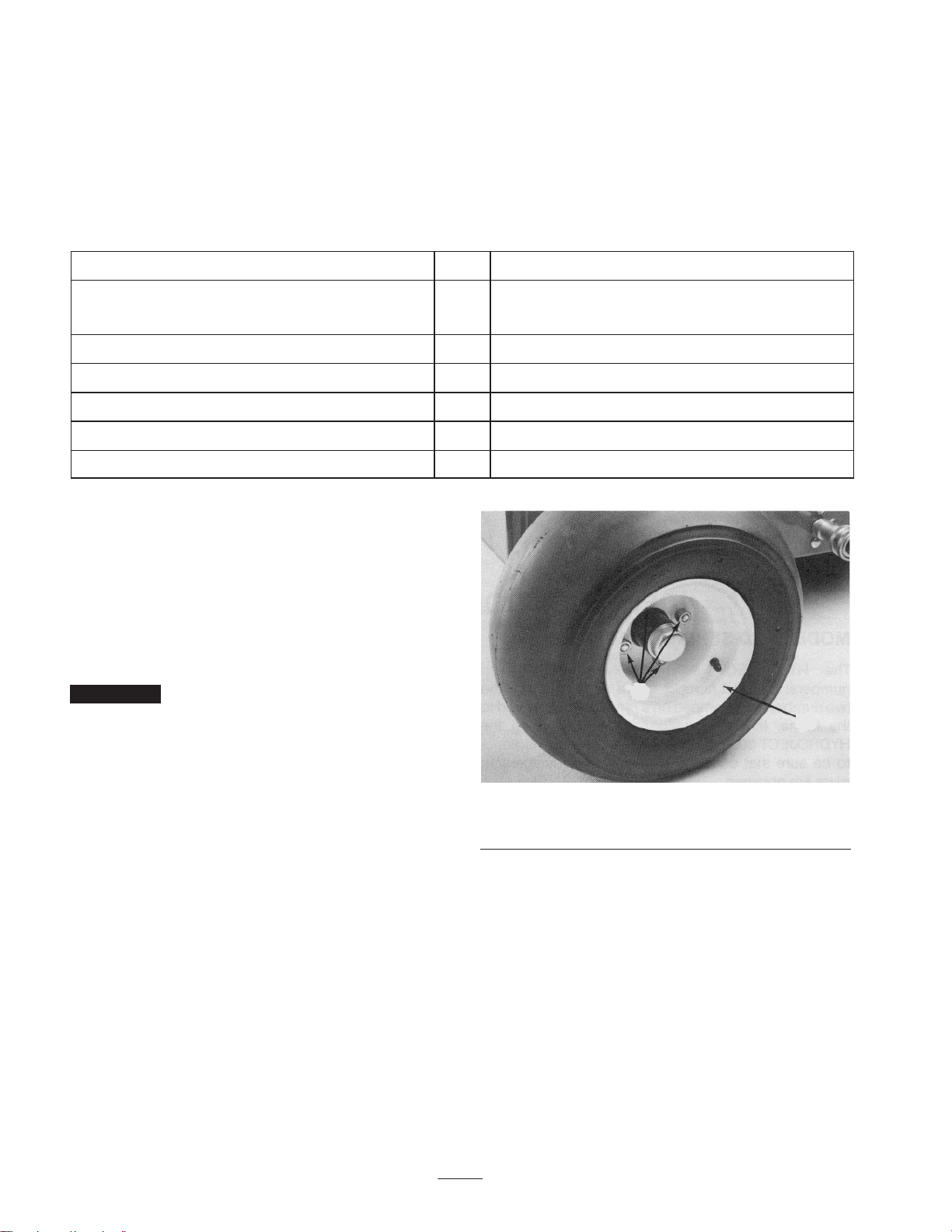
Installing the Rear Wheels
1. Remove the wheels from the shipping pallet.
2. Mount the wheels to the hubs with the lug nuts
(supplied in loose parts) (Fig. 1) and torque the nuts to
45–55 ft.-lb. (61–75 N⋅m).
3. Remove any shipping blocks or braces, which may
obstruct machine removal from the pallet.
Important Refer to the Before Operating section in this
manual, page 13, for instructions on preparing the machine
for operation.
2
1
Figure 1
1. Wheel 2. Lug nuts
12
Page 13
Before Operating
Activating and Charging the
Battery
Warning
Battery posts, terminals, and related accessories
contain lead and lead compounds, chemicals
known to the State of California to cause cancer
and reproductive harm. Wash hands after
handling.
1. Since the battery is not filled with electrolyte or
activated, bulk electrolyte with 1.260 specific gravity
must be purchased from a local battery supply outlet.
Danger
1
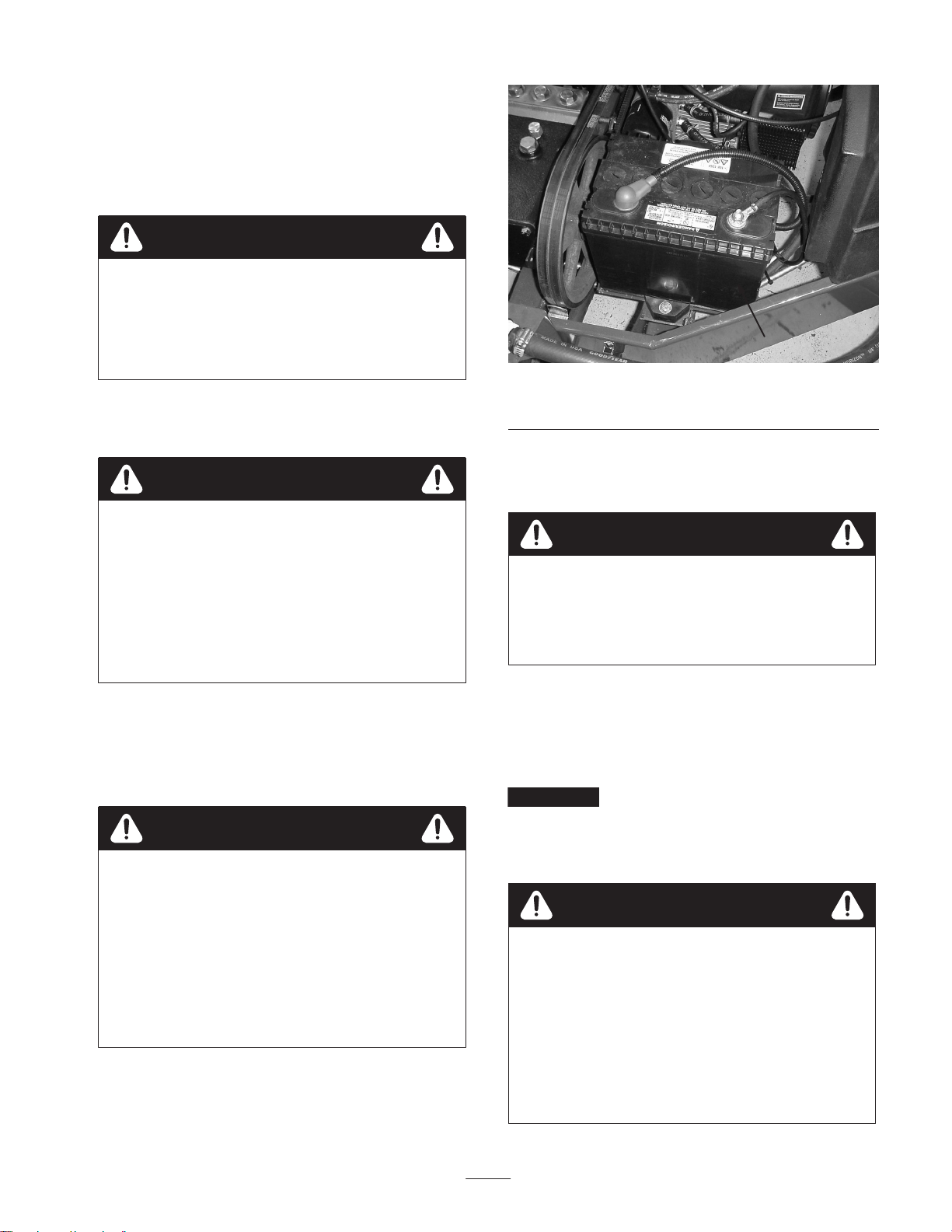
Figure 2
1. Battery
4. Replace the filler caps and connect a 3 to 4 amp battery
charger to the battery posts. Charge the battery at a rate
of 3 to 4 amperes for 4 to 8 hours.
Battery electrolyte contains sulfuric acid which is a
deadly poison and causes severe burns.
• Do not drink electrolyte and avoid contact with
skin, eyes or clothing. Wear safety glasses to
shield your eyes and rubber gloves to protect
your hands.
• Fill the battery where clean water is always
available for flushing the skin.
2. Release the hood latches and raise the hood.
3. Loosen the capscrew securing the battery clamp to the
machine and remove the battery (Fig. 2). Remove the
filler caps from the battery and slowly fill each cell until
electrolyte is just above the plates.
Warning
Battery terminals or metal tools could short
against metal aerator components causing sparks.
Sparks can cause the battery gasses to explode,
resulting in personal injury.
• When removing or installing the battery, do not
allow the battery terminals to touch any metal
parts of the aerator.
• Do not allow metal tools to short between the
battery terminals and metal parts of the aerator.
Warning
Charging the battery produces gasses that can
explode.
Never smoke near the battery and keep sparks and
flames away from battery.
5. When the battery is charged, disconnect the charger
from the electrical outlet and battery posts.
6. Remove the filler caps. Slowly add electrolyte to each
cell until the level is up to the fill ring. Install the filler
caps.
Important Do not overfill the battery. Electrolyte will
overflow onto other parts of the machine and severe
corrosion and deterioration will result.
7. Install the battery and secure it with the battery clamp.
Warning
Incorrect battery cable routing could damage the
aerator and cables causing sparks. Sparks can
cause the battery gasses to explode, resulting in
personal injury.
• Always disconnect the negative (black) battery
cable before disconnecting the positive (red)
cable.
• Always connect the positive (red) battery cable
before connecting the negative (black) cable.
13
Page 14
8. Install the positive cable (rubber boot over end) to the
positive (+) terminal and the negative cable (black) to
the negative (–) terminal of the battery and secure them
with capscrews and nuts. Slide the rubber boot over the
positive terminal to prevent a possible short-out from
occurring (Fig. 2).
9. Lower the hood and secure the latches.
Checking the Engine Oil
The engine is shipped with oil in the crankcase; however,
the oil level must be checked before and after the engine is
first started.
Crankcase capacity is approximately 2 qt. (1.4 l) with the
filter.
Use high-quality engine oil that meets the following
specifications:
API Classification Level Required: SJ, SK, SL or
higher.
Note: If the oil level is at the ADD mark on the dipstick,
add 1 quart of oil to raise the oil level to FULL. Do not
overfill.
3. Remove the cap from the oil fill. Pour oil into the oil fill
until the level is at the FULL mark on the dipstick.
Important The aerator operates at very high engine
loads, so check the oil level every 8 operating hours or
daily. A new engine may consume some oil until it is
broken in. Initially, change the oil after the first 25 hours of
operation; thereafter, under normal conditions, change the
oil and filter after every 100 hours of operation. Change the
oil more frequently when the engine is operated in
extremely dusty or dirty conditions.
Filling the Gas Tank
We recommend the use of fresh, clean, unleaded regular
grade gasoline. Unleaded gasoline burns cleaner, extends
engine life, and promotes good starting by reducing the
build-up of combustion chamber deposits.
Preferred oil: SAE 10W–30 (above 0_F)
Alternate oil: SAE 5W–30 (below 32_F)
Toro Premium Engine oil is available from your distributor
in 10W–30 viscosity. See the parts catalog for part
numbers.
1. Position the machine on a level surface.
2. Remove the dipstick from the oil filler neck (Fig. 3) and
wipe it with a clean rag. Insert the dipstick into the filler
neck and make sure it is seated fully. Pull the dipstick
from the filler neck and check the oil level. If the oil
level is low, add enough oil to raise the level to the
FULL mark on the dipstick.
1
2
Note: Do not mix oil with the gasoline. Never use
methanol, gasoline containing methanol, gasohol, gasoline
additives, premium gasoline, or white gas because engine
and fuel system damage could result.
1. Remove the cap from the fuel tank (Fig. 4) and fill the
10 gallon tank to about 1 inch (25 mm) from the top of
tank (the bottom of the filler neck) with unleaded
gasoline. Install the fuel tank cap tightly.
1
Figure 4
1. Fuel tank cap
Figure 3
1. Dipstick 2. OIl fill cap
2. Wipe up gasoline that may have spilled to prevent a fire
hazard.
14
Page 15

Danger
In certain conditions, gasoline is extremely
flammable and highly explosive. A fire or
explosion from gasoline can burn you and others
and can damage property.
• Fill the fuel tank outdoors, in an open area,
when the engine is cold. Wipe up any gasoline
that spills.
• Do not fill the fuel tank completely full. Add
gasoline to the fuel tank until the level is 1 in.
(25 mm) below the bottom of the filler neck.
This empty space in the tank allows gasoline to
expand.
• Never smoke when handling gasoline, and stay
away from an open flame or where gasoline
fumes may be ignited by a spark.
• Store gasoline in an approved container and
keep it out of the reach of children. Never buy
more than a 30-day supply of gasoline.
• Always place gasoline containers on the ground
away from your vehicle before filling.
• Do not fill gasoline containers inside a vehicle or
on a truck or trailer bed because interior
carpets or plastic truck bed liners may insulate
the container and slow the loss of any static
charge.
• When practical, remove gas-powered equipment
from the truck or trailer and refuel the
equipment with its wheels on the ground.
• If this is not possible, then refuel such
equipment on a truck or trailer from a portable
container, rather than from a gasoline dispenser
nozzle.
• If a gasoline dispenser nozzle must be used, keep
the nozzle in contact with the rim of the fuel
tank or container opening at all times until
fueling is complete.
Note: Toro will not assume responsibility for damage
caused by improper substitutions, so use only products
from reputable manufacturers who will stand behind their
recommendation.
Antiwear Hydraulic Fluid, ISO VG 68
Material Properties:
Viscosity, ASTM D445 cSt @ 40_C 65 to 71
cSt @ 100_C 8.4 to 8.9
Viscosity Index ASTM D2270 97 to 107
Pour Point, ASTM D97 –18_F to –30_F
Industry Specifications:
Vickers I–286–S (Quality Level), Vickers M–2950–S
(Quality Level), Denison HF–0
Note: Many hydraulic fluids are almost colorless, making it
difficult to spot leaks. A red dye additive for the hydraulic
system oil is available in 2/3 oz. (20 ml) bottles. One bottle
is sufficient for 4–6 gal (15–22 1) of hydraulic oil. Order
part no. 44–2500 from your authorized Toro distributor.
1. Position the machine on a level surface.
2. Release the hood latches and raise the hood.
3. Check the level of hydraulic oil on the sight gauge
(Fig. 5). The fluid level should be up to the middle of
the gauge window.
2
Checking the Gear Case Fluid
Level
The machines reservoir is filled at the factory with
approximately 4–5 quarts of high quality hydraulic fluid.
Check the level of the hydraulic fluid, on the sight
gauge, before the engine is first started and daily
thereafter. The recommended replacement fluid is:
Mobil DTE 26
Alternate fluids: If this fluid is not available, other fluids
may be used provided they meet all the following material
properties and industry specifications. We do not
recommend the use of synthetic fluid. Consult with your
lubricant distributor to identify a satisfactory product.
1
Figure 5
1. Sight gauge 2. Filler cap
4. If the fluid level is low, remove the filler cap and add
enough hydraulic oil to bring the oil up to the proper
level.
5. Lower the hood and secure the latches.
Important The oil and filter must be changed
immediately when any contamination, sludge, water or
condensation appears in oil or on sight gauge. Determine
and correct oil contamination problem before restarting
engine and operating machine.
15
Page 16

Checking the Pump Case Fluid
Level
4. If the fluid level is low, add enough Mobil DTE Extra
Heavy oil or equivalent oil to bring the oil up to the
proper level. Do not overfill.
The pump crank case is filled at the factory with
approximately 40 ounces of Mobil DTE Extra Heavy oil.
Check the oil level on the dipstick before the engine is first
started and daily thereafter. Change the oil initially after
25 hours of operation, thereafter change every 200 hours
of operation. See the chart below for equivalent oils.
Shell Morlina Sd 150
Chevron AW Machine Oil 150
Conoco Multipurpose R&O
0.1 150
Exxon Terresstic 150
Philllips Magnus Oil 150
Sun Sunvis 150
76 Lubricants Turbine Oil 150
Castrol Paradene 150 R&O
Important The oil must be changed immediately when
any contamination, sludge, water, or condensation appears
in the oil. Determine and correct any oil contamination
problem before restarting the engine and operating the
machine.
1. Position the machine on a level surface.
2. Release the hood latches and raise the hood.
3. Remove the dipstick/filler cap and check the oil level on
the dipstick. The fluid level should be up to the FULL
mark (Fig. 6).
5. Lower the hood and secure the latches.
Checking the Tire Pressure
The tires are over inflated for shipping. Make sure that the
front and rear tires are inflated to 8 to 12 p.s.i. (55 to
83 kPa).
Checking the Accumulator
Charge
Have the accumulator charge checked before and after each
operating season by an Authorized Toro Distributor.
Warning
Charge accumulators contain high pressure
nitrogen. Nitrogen is the only gas to use for
accumulator charging. Installing improper gases in
an accumulator can cause an explosion and death.
Charging requires special tools and precautions.
• Charge the accumulator in a well ventilated
area.
• Have the accumulator checked and charged by
an Authorized Toro Distributor.
• Wear eye protection.
• Keep your hands and face away from the gas
valve.
1. Dipstick/filler cap
Figure 6
Warning
Failure to open the bleed valve before servicing
high pressure water components can cause
1
FULL
personal injury, dismemberment, or death.
Slowly open the high pressure water bleed valve
before servicing any component connected to the
high pressure water system. Opening the high
pressure bleed valve allows any trapped water to
escape from the system and also allows the
accumulator piston to move to the bottom of the
accumulator cylinder.
16
Page 17

Operation
Note: Determine the left and right sides of the machine
from the normal operating position.
Spray Wash Control
Pull the handle (Fig. 7) upward to activate the roller spray
wash system. Move the control knob up or down to adjust
the spray rate to keep the rollers free of debris.
Controls
Ignition Switch
The ignition switch (Fig. 7), which is used to start and stop
the engine, has three positions: OFF, ON, and START.
4
1
2
8
6
7
3
1. Ignition switch
2. Choke
3. Throttle
4. Spray wash control
5. Hour meter
6. Water pressure gauge
Figure 7
7. Circuit breaker reset
button
8. Spacing control lever
9. Accumulator pressure
lights
9
5
Hour Meter
The hour meter (Fig. 7) registers accumulated hours of
engine operation. Use the hour meter to determine intervals
for service maintenance and lubrication.
Water Pressure Gauge
The water pressure gauge (Fig. 7) registers supply water
pressure in the system. It also acts as an interlock switch,
preventing the water pump from starting if the water
pressure is below 20–28 p.s.i., or stopping the water pump
if the water pressure drops below 7–13 p.s.i. Check the
gauge frequently to monitor the water pressure.
Circuit Breaker Reset Button
Push the button (Fig. 7) to reset the breaker after correcting
a malfunction in the electrical system. The button also
serves as a switch to interrupt power to the relays.
Spacing Control Lever
Moving the control (Fig. 7) away from the handle increases
the aerating ground speed and the distance between holes.
Moving the control toward the handle decreases the
aerating ground speed and the distance between holes. The
setting will be overridden when the machine is shifted to
the transport position.
Choke
To start the engine, close the carburetor choke by pulling
the choke control (Fig. 7) outward to the FULL position.
After the engine starts, regulate the choke to keep the
engine running smoothly. As soon as possible, open the
choke by pushing it inward to the OFF position.
Throttle
The throttle (Fig. 7) is used to regulate the engine speed.
Moving the throttle forward increases the engine speed
(FAST); rearward decreases the engine speed (SLOW).
Accumulator Pressure Lights
The high or low pressure lights (Fig. 7) will only illuminate
if a high or low pressure condition occurs in the
accumulator. If a light illuminates the system willl not
operate or shut down.
Traction Bail
The traction bail (Fig. 8) engages and regulates fore and aft
traction operation of the machine. Releasing the bail stops
traction operation and will also stop water injection in 3 to
4 seconds, unless the bail is re–engaged. The transport
speed is regulated by the amount the bail is moved.
17
Page 18

5
2
4
3
Operating Precautions
Follow these precautions when operating the aerator:
Figure 8
1. Traction bail
2. Transport/aerate rocker
switch
3. Aeration engagement
button
4. Aeration stop button
5. Parking brake
Transport/Aerate Rocker Switch
The switch (Fig. 8) lowers machine onto the rollers to
commence aeration. The switch will override the spacing
control setting when it is moved to the transport position.
Aeration Engagement Button
Depressing the button (Fig. 8), starts the water injection
system only when the water pressure is above 28 p.s.i. and
the rollers are on the ground.
1
• Before aerating, inspect the work area for debris and
determine the best direction and pattern to operate the
machine.
• If the machine starts to vibrate abnormally, shut the
engine off. Remove the wires from the spark plugs to
prevent the possibility of accidental starting. Check the
machine for damaged parts. Repair any damage before
restarting the engine and operating the machine.
• Only use the aerator in daylight or when there is good
artificial light. Watch for holes or other hidden hazards.
Do not transport the machine close to a sand trap, ditch,
creek, or other hazard.
• To prevent roller marks, always raise the machine to the
transport position when parked on a green.
• Do not operate the water injection system on concrete
or asphalt because water jets will permanently damage
these surfaces. Do not run over the hose as damage will
occur.
• Do not operate the aerator with the roller or injection
system over the edge of anything that could be hit,
damaged, or injured by high velocity water blasts.
• Water jets from the injection system should not damage
irrigation heads on one pass of the machine. Do not
allow multiple shots from the injection system to hit
irrigation heads as damage will occur.
• Use a good, clean, quality water supply in the system. If
good quality water is not available, additional filtration
equipment may be required. Do not use chemicals in
the water system.
Aeration Stop Button
The red button (Fig. 8) stops the water injection system.
The system continues for a few seconds after the button is
pressed.
Parking Brake
Push the lever (Fig. 8) toward the machine to engage the
parking brake. A warning buzzer will sound if you attempt
to move the machine with parking brake engaged.
Fuel Shut-Off Valve
The fuel shut-off valve is located under the fuel tank. Close
the valve when storing or transporting (trailering) the
machine.
• Do not allow the machine to be subject to freezing
temperatures without draining, as damage to the system
will occur.
Starting and Stopping the
Engine
1. Make sure that the wires are installed on the spark plugs
and the fuel shut-off valve is open.
2. Make sure that the parking brake is engaged.
3. Pull the choke lever out to the FULL position and move
the throttle lever to the half throttle position.
Note: When starting a warm engine, the choke may not be
necessary, but HALF throttle is.
18
Page 19

4. Insert the key into the ignition switch and rotate it
clockwise to start the engine. Release the key when the
engine starts. Gradually return the choke lever to the
OFF position (lever all the way in) after the engine
starts and warms up.
Important To prevent overheating of the starter motor,
do not engage the starter longer than 30 seconds. After 30
seconds of continuous cranking, wait 2 minutes before
engaging the starter motor again.
Important The engine is equipped with an oil pressure
interlock switch which interrupts the engine operation if
there is not sufficient oil pressure in the engine during
starting or operation. The engine may start but will not
continue to run due to a lack of oil pressure.
2
1
Figure 9
1. Hose adapter 2. Quick coupler
5. To stop the engine, move the throttle control downward
to the SLOW position and turn the ignition key to OFF.
Remove the ignition key.
Training Period
Before aerating with the machine, it is suggested that you
find a clear area and practice starting and stopping, raising
and lowering machine, turning, etc. This training period
will be beneficial to the operator in gaining confidence in
the performance of the aerator.
Water Supply
Recommended source with 7–8 gallons per minute. A
minimum pressure of 30 p.s.i. at the machine is required for
the pump to engage. Maximum allowable pressure of 200
psi. Although irrigation water pumped from ponds or
effluent holding pools can be used, not all conditions can be
handled by the filtration system. Additional or alternative
filtration may be required.
Operating Procedure
4. Turn on the water supply and check the water pressure.
The water pressure must be at least 30 p.s.i.. If the
system pressure is not 30 p.s.i., make sure that the hose
is not kinked or obstructed, the water supply is turned
on, and the water filter is not plugged.
Caution
Do not operate the engine while bleeding the filter
head.
5. Reach under the fuel tank and press the bleed button on
top of the water filter head (Fig. 10). Hold the bleed
button down until all air is purged from the filter and
water comes out of the opening.
2
1. Make sure that the wires are installed on the spark plugs
and the fuel shut-off valve is open.
2. Uncoil a garden hose, making sure that there are no
kinks or bends in the hose. Lay out the hose so that
there are no obstructions between the machine and the
area to be aerated. Turn on the water supply to purge
any air from the hose. Turn off the water.
3. Connect the hose adapter (Fig. 9) to the garden hose,
then connect the adapter to the quick coupler on the side
of the machine.
1
Figure 10
1. Main water filter head 2. Bleed button
19
Page 20

6. Reach under the hood and open the bleed valve on the
main valve at the rear of the machine (Fig. 11). Bleed
the system until a steady flow of water comes from the
outlet; then close the valve.
1
2
Figure 11
1. Main valve 2. Bleed valve
10. Engage and hold the transport/aerate toggle switch to
fully lower the machine onto the rollers. Release the
switch when the machine is fully lowered; then press
the engagement button to start water injection.
Note: The injection operation starts approximately 4–5
seconds after the pump engages. Also, the injection system
will automatically stop if the traction bail is not engaged
within 3–4 seconds after starting the water system.
11. When aerating, work moving perpendicular from the
water supply to avoid running over the garden hose.
Use the front edge of the hood or rear corner of the
frame to align rows, if desired. When at the end of a
row, make an “S” maneuver and reverse the direction of
the aerator. Do not make sharp turns on a green or
scuffing from the tire may occur.
12. Regulate the roller spray wash, if required, to remove
debris from the rollers.
Note: A small amount of water from the regulator bypass
may come out of the spray wash nozzles even with the
spray wash in the “OFF” position.
13. In areas where greater hole depth or more frequent
holes are desired, the engage button can be held down
to allow multiple shots while machine is stopped.
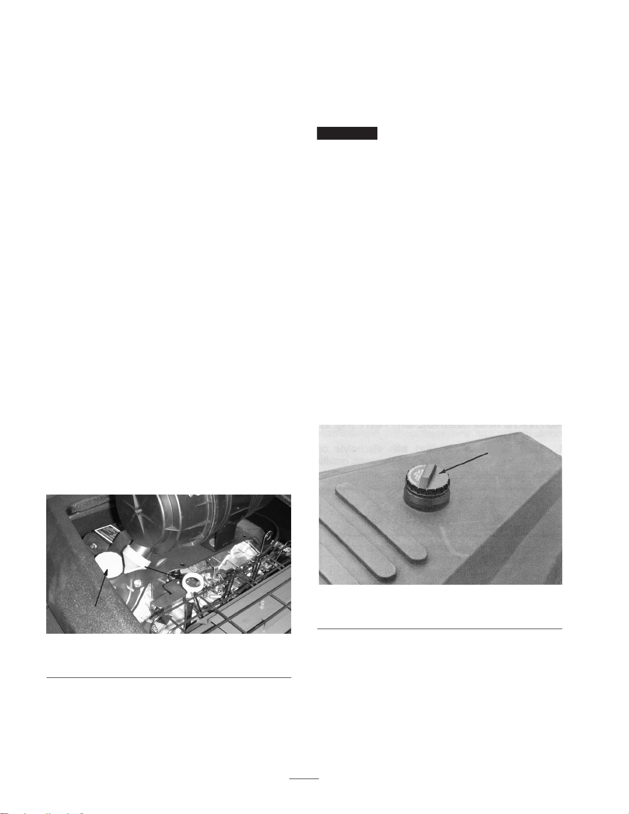
7. If desired, the valve on the pre-filter (Fig. 12) may be
opened slightly (cracked) to provide continuous
flushing during operation of the machine.
1
2
Figure 12
1. Pre-filter 2. Valve
8. Start the engine; refer to Starting and Stopping the
Engine, page 18. Move the throttle to the FAST position
and disengage the parking brake.
9. Engage the traction bail and approach the area to be
aerated. Make sure that there are no obstructions
between the aerator and water supply.
Important Hole depths can reach 20 inches or more
when making multiple shots, so be aware of what is buried
below the turf. Also, an excessive amount of holes and
muddy turf conditions may occur when making multiple
shots.
14. To stop water injection, press the red button. The
system continues for a few seconds after the button is
pressed. Raise the machine to the transport position,
disconnect the supply hose, and move to the next
location.
Checking the Interlock System
Caution
If safety interlock switches are disconnected or
damaged the machine could operate unexpectedly,
causing personal injury.
• Do not tamper with the interlock switches.
• Check the operation of the interlock switches
daily and replace any damaged switches before
operating the machine.
The purpose of the safety interlock system is to prevent the
engine from cranking or starting unless the traction bail is
in NEUTRAL and prevents the water system from
engaging if the machine is in the transport (raised) position.
It also stops aeration if the traction bail is released while
operating or if the machine is raised to the transport
position.
20
Page 21

To do a functional check of interlock system:
1. Position the machine in a flat, open area on rough turf
and away from buried wires, plumbing, etc. Stop the
engine.
2. Move the traction bail up and down while trying to start
the engine. If the engine cranks, there is a malfunction
in the interlock system that must be corrected. If the
engine does not crank, proceed to step 3.
3. Connect the water supply to the machine. Turn on the
water supply and bleed all air out of the system. The
water pressure must be 30 psi or more. Start the engine.
Raise the machine to the transport position (up off the
rollers). Push the aerate ENGAGE button. If the water
pump engages and the machine begins aerating, there is
a malfunction in the interlock system that must be
corrected. If the machine does not begin aerating,
proceed to step 4.
4. Lower the machine to the aerate position (on the
rollers). Engage the traction bail to start the machine
moving. Push, then release the aerate ENGAGE button.
The water pump should engage immediately, then the
machine should begin aerating 5 seconds after the pump
engages. Release the traction bail to the neutral position
so that the machine stops moving. The water pump
should disengage 4 seconds after the traction bail
returns to neutral, then stop aerating after another 3
seconds. If the machine does not stop aerating when the
traction bail returns to neutral, there is a malfunction in
the interlock system that must be corrected. If the
machine stops aerating, proceed to step 5.
5. Engage the traction bail to start the machine moving,
then push the aerate ENGAGE button to begin aerating.
Push the aerate DISENGAGE button. The water pump
should disengage immediately, then stop aerating after 3
seconds. If the machine does not stop aerating, there is a
malfunction in the interlock system that must be
corrected.
Note: Lights (LED’s) on the controller (Fig. 13) indicate
when the following inputs are made to the controller:
Red: Transport switch closed (traction bail in neutral)
Green: Aerate start (engage) switch closed. If the red
and yellow lights are on, the green light will stay on
until either the red or yellow goes off.
Yellow: Pump start limit switch closed (machine
lowered to aerate position) and water pressure switch
closed (water pressure of more than 30 psi) and
accumulator charge pressure switch (nitrogen pressure
more than 1800 psi).
3
2
1
Figure 13
1. Red light
2. Green light
3. Yellow light
Transport Operation
Use the traction bail to slow the machine while crossing
undulating terrain to avoid loss of control. The smooth tires
do not grip turf very well so use caution when transporting
the machine. Always approach rough areas at a reduced
speed and cross severe undulations carefully.
Inspection and Clean-Up After
Use
At the completion of operation, thoroughly wash the
machine with a garden hose without a nozzle so excessive
water pressure will not cause contamination and damage to
seals and bearings. After cleaning, it is recommended the
machine be inspected for possible hydraulic fluid or water
leaks and damage or wear to hydraulic, water, and
mechanical components.
Pushing or Towing the Machine
In an emergency, the machine can be pushed or towed for a
very short distance. However, we do not recommend this as
standard procedure.
Important Do not push or the tow machine faster than
3 MPH because pump damage may occur. If the machine
must be moved a considerable distance, transport it on a
truck or trailer or pull it with the traction wheel raised and
secured to a dolly (Optional Hydrotote Trailer, Model
09833 available). Whenever the machine is pushed or
towed, the bypass valve must be opened. The hook on the
front of the handle is used as a tie-down only, not a hitch
point.
1. Unlatch and raise the hood.
2. Locate the bypass valve cap on the left side of the
hydraulic pump (Fig. 14).
3. Rotate the valve cap counterclockwise, move the
machine to the desired location, and close the valve cap.
4. Lower the hood and secure the latches.
21
Page 22

Important Do not use chemicals! Concern for
environmental issues and corrosive affects on machine
components.
1
Figure 14
1. Bypass valve
22
Page 23

Maintenance
Note: Determine the left and right sides of the machine from the normal operating position.
Recommended Maintenance Schedule
Maintenance Service
Interval
After first 25 hours
After first 50 hours
Every 50 hours
Every 100 hours
Every 200 hours
Every 400 hours
Every 1000 hours or 2
years, whichever occurs
first
Maintenance Procedure
• Change the engine oil and filter.
• Change the gear case oil and filter.
• Change the pump case oil.
• Torque the wheel lug nuts.
• Check the engine RPM (idle and full throttle).
• Check the battery cable connections.
• Lubricate all grease fittings.
• Change the engine oil and filter.
• Replace the primary air filter element.
• Check the inner air filter element.
• Replace the fuel filter.
• Adjust the water system cam—valve clearance.
• Change the gear case oil and filter.
• Change the pump case oil.
• Torque the wheel lug nuts.
• Adjust the parking brake.
• Calibrate the aeration traction speed.
• Service the injector nozzles and springs.
• Replace the spark plugs.
• Check the engine RPM (idle and full throttle).
• Replace moving hoses.
• Replace safety switches.
• Drain and flush the fuel tank.
• Drain and flush the hydraulic tank.
Water System Accumulator
Due to the operational requirements of the accumulator design, the high pressure internal gas pre–charge can bleed out during
periods of inactivity. Storing the Hydroject for extended periods of time (3 months or longer) and/or seasonal temperature
variances can affect the accumulators ability to retain a sufficient pre–charge and seasonal servicing (recharge ) may be
required.
If one of the accumulator charge indicator lamps illuminates, contact your authorized Toro Distributor for accumulator
maintenance services.
_____
23
Page 24

Daily Maintenance Checklist
Duplicate this page for routine use.
For the week of:
Maintenance Check Item
Check safety interlock operation.
Check brake operation.
Check the engine oil level.
Check the engine air filter pre-cleaner.
Check the engine cooling fins for debris.
Check unusual engine noises.
Check unusual operating noises.
Check the water filter/pressure.
Check the water pre-filter.
Check the gear case oil level.
Check the pump case oil level.
Check they hydraulic hoses for damage.
Check for fluid leaks.
Check the tire pressure.
Check instrument operation.
Lubricate all grease fittings.
1
Mon. Tues. Wed. Thurs. Fri. Sat. Sun.
Touch up damaged paint.
1
Immediately after every washing, regardless of the interval listed
Notation for Areas of Concern
Inspection performed by:
Item Date Information
1
2
3
4
5
6
7
8
9
10
11
12
13
24
Page 25

Caution
If you leave the key in the ignition switch, someone
could accidently start the engine and seriously
injure you or other bystanders.
Remove the key from the ignition and disconnect
the wire from the spark plug before you do any
maintenance. Set the wire aside so that it does not
accidentally contact the spark plug.
Caution
Contact with hot surfaces could cause burns.
Wait for the unit to cool before servicing or
making adjustments to the machine.
Lubricating the Machine
The aerator has 5 grease fittings that must be lubricated
every 50 hours of operation with No. 2 General Purpose
Lithium Base Grease. Lubricate all fittings immediately
after every washing, regardless of the interval listed.
The bearings and bushings that must be lubricated are:
steering pivot shaft (Fig. 15), limit switch housing (Fig. 16)
(2) lift arm shaft (Fig. 16), and neutral pivot shaft (Fig. 17).
Figure 16
Figure 17
1. Wipe the grease fitting clean so that foreign matter
cannot be forced into the bearing or bushing.
Figure 15
2. Pump grease into the bearing or bushing.
3. Wipe up excess grease.
25
Page 26

Servicing the Pre-Filter
Sediment can be removed by opening the ball valve, with
the water source attached, to flush (Fig. 18). The reusable
filter screen may be removed for cleaning by untwisting the
clear cover (Fig. 18) from the filter by hand. Replace the
clear cover and hand tighten only.
Important Use of tools will damage the filter.
4
3
1
2
3
Figure 18
1. Body
2. Clear cover
3. Ball valve for flushing
Replacing the Main Water Filter
The machine is a precision piece of equipment and the
quality or cleanliness of your water supply is very
important in determining the life of the machine. If your
water supply contains silt, sand, or other debris, you may be
required to install additional filtration or separation
equipment between your supply source and the machine.
Depending on the quality of water, the frequency of the
filter change will vary greatly. When the pump inlet
pressure decreases or the water system shuts down, it
usually means the water filter is restricted and must be
replaced. Never operate machine without a water filter
as severe damage may occur.
1. Position the machine on a level surface and make sure
that the engine is shut off. Shut off the water supply.
2. Locate the main water filter assembly mounted below
the fuel tank. Press the bleed button (Fig. 19) to release
air pressure from the filter body.
2
Figure 19
1. Filter body
2. Filter cartridge
3. Filter head
3. Unscrew the filter body of the assembly (Fig. 19)
counterclockwise (as viewed from the bottom). Remove
the filter cartridge and discard it.
Note: To ease the removal of the filter body from the filter
head, a filter wrench is available. Contact your Authorized
Toro Distributor.
4. Bleed button
5. O-ring
5
1
Caution
The water filter body is very heavy when filled
with water and the filter. Use caution when
unscrewing the filter body from the filter head.
4. Thoroughly rinse out the filter body to avoid
contaminating the water system. Make sure that the
o-ring (Fig. 19) is in the groove. If it has come out,
wipe it dry, lubricate it with a light coating of petroleum
jelly, and replace it in the groove.
5. Thoroughly clean the filter head mounting surface to
avoid contaminating the water system when the filter is
installed.
6. Insert the new filter cartridge into the filter body.
7. Thread the filter body with the filter onto the filter head.
Hand tighten them.
8. Turn on the water supply and press the bleed button on
the top of the water filter head (Fig. 19). Hold the bleed
button down until all air is purged from the filter and
water comes out of the opening.
26
Page 27

Changing the Engine Oil and
Filter
For new engines, change the oil after the first 50 operating
hours. Thereafter, under normal conditions, change the oil
and the filter after every 100 hours of operation. However,
an engine operated in dusty or dirty conditions requires
more frequent oil changes. If possible, run the engine just
before changing the oil. Warm oil flows more freely and
carries more contaminants than cold oil.
1. Position the machine on a level surface.
2. Disengage the hood latches and open the hood.
3. Place an oil drain pan below the drain hose on the side
of the crankcase (Fig. 20).
4. Rotate the drain valve counter–clockwise and allow the
oil to flow into a drain pan. After the oil has drained,
rotate the oil drain valve clockwise.
2
1
Figure 21
1. Dipstick 2. Filler cap
5. Remove the oil filter (Fig. 20) and discard it.
Thoroughly clean the filter mounting surface and make
sure that a new gasket is installed in the new filter.
1
2
Figure 20
1. Oil drain valve 2. Oil filter
6. Apply a thin film of clean oil to the gasket. Install a
new filter by hand until the gasket just touches the
mounting surface, then turn the filter an additional 1/2
to 3/4 turn.
7. Remove the filler cap (Fig. 21) and pour approximately
2 quarts of oil into the filler neck.
8. Start the engine and check for leaks around the oil filter.
Tighten the filter only enough to eliminate leaks. Do
not overtighten.
9. Turn off the engine and allow the machine to stand for 2
minutes.
10. Check the oil and make sure that the level is up to the
FULL mark on the dipstick. Add more oil if the level is
low; however, do not overfill.
11. Lower the hood and secure the latches.
General Air Cleaner
Maintenance
• Check the air cleaner body for damage which could
cause an air leak. Replace if damaged. Check the whole
intake system for leaks, damage or loose hose clamps.
• Service the air cleaner filter every 200 hours or earlier if
engine performance suffers due to extremely dusty,
dirty conditions. Changing the air filter before it is
necessary only increases the chance of dirt entering the
engine when the filter is removed.
• Be sure the cover is seated correctly and seals with the
air cleaner body.
Servicing the Air Cleaner
The primary air cleaner element must be checked and/or
replaced after every 200 hours of engine operation.
However, the air cleaner must be cleaned more frequently if
operating conditions are extremely dusty or sandy.
27
Page 28
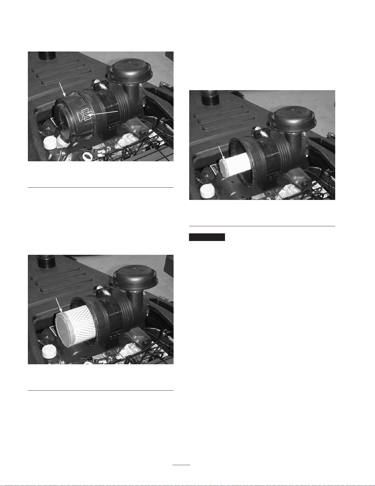
1. Release the latches and securing the air cleaner cover to
the air cleaner body (Fig. 22).
3. Remove and replace the primary filter. Cleaning of the
used element is not recommended due to the possibility
of damage to the filter media. Inspect the new filter for
shipping damage, checking the sealing end of the filter
and the body. Do not use a damaged element.
1
2
Figure 22
1. Air cleaner cover 2. Latch
2. Remove the cover from the air cleaner body. Before
removing the filter, use low pressure air (40 psi, clean
and dry) to help remove large accumulations of debris
packed between outside of primary filter and the
canister. Avoid using high pressure air which could
force dirt through the filter into the intake tract. This
cleaning process prevents debris from migrating into
the intake when the primary filter is removed.
4. Inspect the safety element and replace it if is dirty or
damaged.
1
Figure 24
1. Safety element
Important Do not wash the safety element or clean it
with compressed air as damage will occur.
5. Insert the new filter by applying pressure to the outer
rim of the element to seat it in the canister. Do not apply
pressure to the flexible center of the filter.
1
1. Primary element
Figure 23
6. Clean the dirt ejection port located in the removable
cover. Remove the rubber outlet valve from the cover,
clean the cavity and replace the outlet valve.
7. Install the cover orienting the rubber outlet valve in a
downward position – between approximately 5:00 to
7:00 when viewed from the end.
8. Install the air cleaner and secure the latches.
Checking and Replacing the
Spark Plugs
Since the air gap between the center and side electrodes
increases gradually during normal engine operation, check
the spark plugs at 200 hour intervals and replace as
required. The correct spark plug to use in the engine is a
Champion RC12 YC or equivalent. Set the air gap at
.040 in.
1. Disengage the hood latches and open the hood.
28
Page 29

2. Clean the area around the spark plugs (Fig. 25) so that
dirt does not fall into the cylinder when the plugs are
removed.
Figure 25
1. Spark plug
Important The gear case oil and filter must be changed
immediately when any contamination, sludge, water or
condensation appears.
1. Disengage the hood latches and open the hood.
2. Place a drain pan under the bottom of the gear case.
Clean the area around the drain plug (Fig. 26).
Note: When draining the oil, use a funnel or some type of
channel to divert the draining oil away from the machine
components and into a drain pan.
1
3. Pull the wires off of the spark plugs and remove the
plugs from the cylinder head.
4. Check the condition of the center and side electrodes to
determine the operating temperature of the engine.
• Light brown insulator tip indicates correct spark plug
and heat range.
• Black or oily insulator tip indicates an excessively rich
fuel mixture, possibly caused by a dirty air cleaner
element or a carburetor that is set too rich.
• Light gray or blistered-white insulator indicates
overheating caused by a lean carburetor setting or
incorrect spark plug (heat range too high).
Important A cracked, fouled, or dirty spark plug must
be replaced. Do not sandblast, scrape, or clean the
electrodes by using a wire brush because grit may release
from the plug and enter the combustion chamber, resulting
in engine damage.
5. After setting the air gap at .040 in., install the spark
plugs in the cylinder head. Tighten the plugs to
18–22 ft.-lb. (24–30 N⋅m). Push the wires onto the
spark plugs.
6. Lower the hood and secure the latches.
Figure 26
1. Drain plug location
3. Remove the drain plug and allow the oil to flow into a
drain pan. After the oil has drained, install the oil drain
plug.
4. Remove the oil filter (Fig. 27), mounted below control
panel base, and discard the filter. Thoroughly clean the
filter mounting surface and make sure that a new gasket
is installed in the new filter.
1
Figure 27
1. Oil filter
Changing the Gear Case Oil
and Filter
Change the hydraulic oil and filter initially after 25 hours of
operation; thereafter change them every 200 hours of
operation.
5. Fill the new filter with new Mobil DTE 26 hydraulic oil
or equivalent oil. Apply a thin film of clean oil to the
filter gasket.
6. Install the new filter by hand until the gasket just
touches the mounting surface, then turn it an additional
1/2 to 3/4 turn.
29
Page 30

7. Remove the filler cap and add approximately 4–5 quarts
of Mobil DTE 26 hydraulic oil or equivalent oil to the
gear case reservoir. Install the filler cap.
Checking the Hydraulic Lines
and Hoses
8. Check for leaks around the oil filter. Tighten the filter
only enough to eliminate leaks. Do not overtighten.
9. Lower the hood and secure the latches.
Changing the Pump Case Oil
Change the pump oil initially after 25 hours of operation;
thereafter change it every 200 hours of operation.
Important The pump case oil must be changed
immediately when any contamination, sludge, water or
condensation appears.
1. Disengage the hood latches and open the hood.
2. Place a drain pan under the pump case. Clean the area
around the drain plug on the bottom of the case
(Fig. 28).
Note: When draining the oil, use a funnel or some type of
channel to divert the draining oil away from the machine
components and into a drain pan.
3. Remove the drain plug and allow oil to flow into a drain
pan. After the oil has drained, install the oil drain plug.
4. Remove the dipstick/filler cap and add approximately
40 ounces of Mobil DTE Extra Heavy oil or equivalent
to the pump case. Install the filler cap.
Check the hydraulic lines and hoses daily for leaks, kinked
lines, loose mounting supports, wear, loose fittings, weather
deterioration, and chemical deterioration. Make all
necessary repairs before operating.
Warning
Hydraulic fluid escaping under pressure can
penetrate skin and cause injury.
• Make sure all hydraulic fluid hoses and lines are
in good condition and all hydraulic connections
and fittings are tight before applying pressure to
the hydraulic system.
• Keep your body and hands away from pin hole
leaks or nozzles that eject high pressure
hydraulic fluid.
• Use cardboard or paper to find hydraulic leaks.
• Safely relieve all pressure in the hydraulic
system before performing any work on the
hydraulic system.
• Get immediate medical help if fluid is injected
into skin.
Adjusting the Traction Pump
Belt
1
Figure 28
1. Drain plug location
5. Check the oil level. If the fluid level is low, add enough
Mobil DTE Extra Heavy oil or equivalent to bring the
oil up to the proper level. Do not overfill.
6. Check for possible leaks. Lower the hood and secure
the latches.
Make sure that the traction pump belt is properly tensioned
to ensure correct operation of the unit and unnecessary
wear. Check the belt midway in the span of the belt.
1. Disengage the hood latches and open the hood.
2. Check the belt tension by depressing the belt midway
between the pulleys with 3 lb. of force. The belt should
deflect 9/64 in. (Fig. 29).
1
Figure 29
1. Traction pump belt
30
Page 31

3. If an adjustment is necessary, adjust as follows:
A. Loosen the pivot nut securing the pump mount to
the pump support (Fig. 30).
2
3
1
2
3
1
Figure 30
1. Pump
2. Pivot nut
B. Loosen the adjusting nut securing the pump and
pump mount to the slotted pump support (Fig. 30).
C. Loosen the 3 capscrews securing the pulley guard
bracket to the control panel and pump support.
D. Use a pry bar to pull the pump toward the outside of
the machine until the proper belt tension is attained;
then tighten the adjusting nut securing the pump and
pump mount to the pump support (Fig. 30).
E. Tighten the pivot nut securing the pump mount to
the pump support (Fig. 30).
F. Tighten the 3 capscrews securing the pulley guard
bracket to the control panel and pump support.
3. Adjusting nut
Adjusting the Transmission for
Neutral
Figure 31
1. Neutral adjustment cam
2. Locknut
5. Move the traction bail completely up and down. Release
the handle and check for wheel rotation. If the wheel
continues rotating, repeat step 4.
6. If the problem continues, stop the engine, check the
linkage for binding or damage, then do the adjustment
procedure again.
7. Set the hole spacing control in the lowest setting (to the
left) and move the transport/aerate switch to the aerate
position (transport tires retracted). Loosen the 2 screws
and adjust the switch tab (Fig. 31) so that the switches
are actuated when the pump control is in neutral and not
actuated when the pump is stroked.
8. Move the ignition switch to the ON position, but do not
start the engine. Move the traction bail in both
directions; the red traction light should come on. Repeat
step 7 if the light does not come on when the bail is
moved in both directions. The second limit switch must
simultaneously activate when the red traction light is
OFF. This switch enables the engine start circuit.
3. Switch tab
If the machine moves when the lever is released, an
adjustment to the transmission neutral is required.
1. Park the machine on a level surface, stop the engine,
and open the hood.
2. Lift the drive wheel off of the ground using a jack.
Block the front and rear of the wheels.
3. Start the engine and release the parking brake.
4. Slightly loosen the locknut on the top of the neutral
adjustment cam (Fig. 31) and rotate the cam hex until
the traction wheel stops rotating. Tighten the locknut.
Adjusting the Aeration Speed
1. Park the machine on a level surface, stop the engine,
and open the hood.
2. Put the speed control lever (Fig. 32) into the second slot
from the left (while facing the control panel).
3. Lower the machine into aerate mode so that the
transport wheels are off of the ground.
4. Lift the drive wheel off of the ground using a jack.
5. Start the engine and release the parking brake.
6. Operate the engine at full speed.
7. Move the traction handle UP to full speed.
31
Page 32

8. Loosen the jam nuts and adjust the LOWER speed rod
(Fig. 32) until the traction wheel rotates at 20–22 RPM.
Tighten the jam nuts.
9. Move the traction handle DOWN to the full speed
position.
10. Adjust the UPPER speed rod (Fig. 32) until the traction
wheel rotates at 20–22 RPM. Tighten the jam nuts.
1
2. Loosen the upper jam nut securing the brake cable to
the bracket (Fig. 34).
1
Figure 34
1. Brake cable
3. Tighten the lower jam nut until 25 to 30 pounds of force
are required to actuate the brake lever. Tighten the jam
nut.
2
Figure 32
1. Speed control lever
2. Lower control rod
3
3. Upper control rod
Adjusting the Parking Brake
Adjust the parking brake every 400 hours.
1. Remove the screws securing the cover to the underside
of the handle (Fig. 33). Remove the cover.
2
1
4. Install the cover to the underside of the handle.
Adjusting the Roller Spray
Wash System
If the spray wash system (Fig. 35) on the rollers needs to be
adjusted, proceed as follows:
1
Figure 35
1. Roller spray wash system
Figure 33
1. Cover 2. Handle
1. Loosen the cap on the bottom of the fitting (Fig. 36).
2. Rotate the nozzle so that the slot in the tip is parallel to
the roller.
3. Tighten the cap and check the adjustment.
32
Page 33

Warning
3
1. Fitting cap
2. Nozzle
3. Fitting
5
4
2
1
Figure 36
4. Strainer
5. Hex. nut
3
Servicing the Spray Wash
Nozzles or Strainers
To clean or replace the strainers in the spray wash nozzles,
proceed as follows:
1. Loosen and remove the cap on the bottom of the fitting
(Fig. 36).
Incorrect battery cable routing could damage the
aerator and cables causing sparks. Sparks can
cause the battery gasses to explode, resulting in
personal injury.
• Always disconnect the negative (black) battery
cable before disconnecting the positive (red)
cable.
• Always connect the positive (red) battery cable
before connecting the negative (black) cable.
If the machine will be stored more than 30 days, remove
the battery and place it on trickle charge. Either store it on
the shelf or on the machine. Leave the cables disconnected
if it is stored on the machine. Store the battery in a cool
atmosphere to avoid quick deterioration of the charge in the
battery.
2. Remove the nozzle and strainer assembly (Fig. 36).
Clean or replace the strainer and replace it in the nozzle.
3. Loosely secure the nozzle and strainer to the fitting with
the cap.
4. Rotate the nozzle so that slot in the tip is parallel to the
roller.
5. Tighten the cap and check the adjustment.
Caring for the Battery
If the aerator is stored in a location where temperatures are
extremely high, the battery will run down more rapidly than
if the machine is stored in a location where temperatures
are cool.
Keep the top of the battery clean by washing it periodically
with a brush dipped in ammonia or bicarbonate of soda
solution. Flush the top surface with water after cleaning.
Do not remove the fill caps while cleaning.
The battery cables must be tight on the terminals to provide
good electrical contact.
If corrosion occurs at the terminals, disconnect the cables,
negative (–) cable first, and scrape the clamps and terminals
separately. Reconnect the cables, positive cable first, and
coat the terminals with petroleum jelly.
33
Page 34

Seasonal Storage
Preparing the Engine
1. Drain the engine oil from the crankcase.
Preparing the Water System
Important It is very important that the water system be
drained to avoid freezing and damaging the components.
Drain system as follows:
1. Stop the engine, remove the key from the ignition
switch, and remove the wires from the spark plugs.
2. Remove the 2 screws securing the drive shield to the
frame and remove the shield.
3. With the engine “OFF” and the key removed from
ignition, rotate the drive coupling by hand until
resistance is felt. Continue to rotate the coupling about
1/4 revolution, opening the cycling valve.
4. Using the appropriate reducers (National Pipe thread),
connect a source of compressed air (maximum pressure
150 psi; minimum pressure 90 psi) to the water inlets on
either side of the machine.
Danger
Compressed air can penetrate the skin and cause
physical harm.
• Use extreme caution and wear protective goggles
and gloves when working with high pressure air.
• Get prompt medical attention if an injury
occurs.
5. Let compressed air flow through the machine for 3
minutes. While compressed air is flowing, temporarily
open the spray wash and high pressure drain valve,
purging water from the spray wash and high pressure
system.
2. Remove and discard the oil filter. Install a new filter.
3. Refill the engine with 2 qts. of recommended motor oil.
4. Start the engine and run it at idle speed for two minutes.
Do not run it for longer than two minutes.
5. Stop the engine; remove the spark plugs.
6. Pour one ounce of clean engine oil into the spark plug
holes.
7. With the spark plugs removed, crank the engine with
the starter for a least 12 revolutions to distribute oil in
the cylinders.
8. Install the spark plugs.
9. Drain the gasoline from the fuel tank and fuel lines.
Reinstall all lines and secure all connections.
10. Thoroughly clean and service the air cleaner.
11. Check the oil filler cap and fuel tank cap to ensure that
they are securely in place.
Preparing the Traction Unit
1. Thoroughly clean the machine.
2. Grease or oil all fittings and pivot points.
3. Check to make sure that all tires are over-inflated to
20–30 p.s.i.
4. Lightly sand and use touch up paint on all areas that are
scratched, chipped, or rusted.
5. Drain and replace the hydraulic oil and filter on the cam
gear case.
6. Drain and replace the oil in the water pump case.
6. Disconnect compressed air and reducers. Install the
drive shield previously removed and tighten the relief
valve tube.
7. Remove and drain the water filter container. Install a
new filter and replace the filter container.
7. Clean the battery, terminals, and posts with a wire brush
and baking soda solution. Coat the cable terminals and
battery posts with skin over grease or petroleum jelly.
Recharge the battery.
34
Page 35

Troubleshooting
Problem Possible Causes Corrective Action
The unit will not move when the
traction ball is engaged.
The unit will not transport at full
speed.
1. Check that motion occurs at the
pump pivot plate when the
traction ball is moved.
2. The oil level in the hydraulic
reservoir (gearbox) is low.
3. Bypass valve is not fully closed. 3. Close the valve.
4. The traction drive belt tension
is incorrect.
1. The unit is not fully raised to
the transport position.
2. The oil level in the hydraulic
reservoir (gearbox) is low.
3. Bypass valve is not fully closed. 3. Close the valve.
4. The traction drive belt tension
is incorrect.
5. Check that motion occurs at the
pump pivot plate when the
traction ball is moved.
1. Inspect the traction push/pull
cable and override assembly
under the tiller handle.
2. Replenish, if necessary.
4. Adjust the belt tension.
1. Hold the lift toggle switch until
the slip clutch in the actuator
can be heard ratcheting and
the spindle lift arms are nearly
vertical with the rear axle
spindle tipped away from the
engine.
2. Replenish, is necessary.
4. Adjust the belt tension.
5. Inspect the traction push/pull
cable and override assembly
under the tiller handle.
The engine dies during startup.
1. The fuel shut-off valve is
closed.
2. Fuel in the fuel tank is low. 2. Replenish, if necessary.
3. The engine choke is not
operating correctly.
4. Check the engine oil level. 4. The oil pressure switch is
5. Starting conditions are cold
(30°).
1. Open the fuel shut-off valve.
3. Check the choke connections
and operation. Regulate the
choke until the engine is warm
when starting a cold engine.
bypassed during start, but must
activate to protect the engine
while running.
5. Multiple start attempts may be
required to trip the oil pressure
switch.
35
Page 36

Problem Corrective ActionPossible Causes
ygg
gg )
)
The engine dies when the water
system is engaged.
The engine does not start (will not
engage the starter).
The engine is running and the unit
is not producing aeration holes
(the pump or water valve will not
start).
1. The throttle is in the wrong
operating position.
2. The engine speed is set
incorrectly.
3. Engine power is low. 3. Fuel is contaminated, there is a
1. The traction bail is not in the
neutral position.
2. The neutral switch tab is out of
adjustment.
3. The battery voltage is low. 3. Check the battery.
4. There is a malfunction is the
electrical system.
1. The supply hose is kinked,
there is a restriction in the line,
or the valve at the water source
is only partially opened.
1. Put the throttle in the FAST
position when aerating.
2. Adjust the carburetor fast
setting to 3450–3550 RPM.
plugged fuel filter or air filter, or
there is a bad spark plug.
4. Have the system serviced by
an Authorized Toro Distributor.
1. Correct the traction bail
position.
2. Adjust the switch tab until the
red traction light is OFF in
neutral.
4. Check the circuit breaker and
electrical connections.
1. Correct the condition.
2. There is inadequate water
pressure or flow from the
source.
3. Check the water pressure at
the gauge when the pump is
engaged if the water pressure
drops to less than 25 psi, but
was initially higher.
4. Low accumulator pre–charge
pressure (low pressure
indicator light is on) .
5. High accumulator pre–charge
pressure (high pressure
indicator light is on) .
2. Check the water pressure (from
the water source) at the inlet
(8 gpm – 40 psi).
3. Replace the water filter.
4. Have the system serviced by
an Authorized Toro Distributor.
5. Have the system serviced by
an Authorized Toro Distributor.
36
Page 37

Problem Corrective ActionPossible Causes
(pp
pp p
The unit stops aerating in one
direction or stops aerating in the
lowest hole spacing.
The unit is not producing aeration
holes (the pump and valve are
operating correctly).
1. The supply hose is kinked,
there is a restriction in the line,
or the valve at the water source
is only partially opened.
2. There is inadequate water
pressure or flow from the
source.
3. Check the water pressure at
the gauge when the pump is
engaged if the water pressure
drops to less than 25 psi, but
was initially higher.
4. The neutral switch tab is out of
adjustment
1. There is air in the system. 1. Open the main bleed valve to
2. A nozzle(s) is plugged. 2. Inspect the nozzles.
1. Correct the condition.
2. Check the water pressure (from
the water source) at the inlet
(8 gpm – 40 psi).
3. Replace the water filter.
4. Adjust the switch tab until the
red traction light is ON while
the traction bail is actuated in
both directions.
5. The red traction light must be
OFF, when in neutral, to allow
the engine start interlock to
function.
purge air from the system.
The unit is not producing aeration
holes (the injection pump stops
after the unit stops moving).
The holes are shallow or the
improper depth.
3. The soil composition is hard. 3. A different nozzle configuration
may be required.
4. Have the water system
checked by an Authorized Toro
Distributor.
1. This is a normal condition of
the neutral interlock system.
1. There is air in the system. 1. Open the main bleed valve to
2. If the hole depth was
satisfactory earlier, check the
density and moisture content of
the soil.
3. The soil composition is hard. 3. A different nozzle configuration
4. There are too many large
nozzles, causing a loss in
pressure which could damage
the accumulator or other water
system components.
1. The operator must hold the
Engage (start) button to aerate
without moving.
purge air from the system.
2. A different nozzle configuration
may be required.
may be required.
4. Open the bleed valve and
examine the nozzles. Verify the
size and quantity per the
recommendation chart.
5. Have the water system
checked by an Authorized Toro
Distributor.
37
Page 38

Problem Corrective ActionPossible Causes
The water injection system is
making an unusual noise when
aerating.
1. There is air in the system. 1. With the water supply on, open
the bleed valve under the
accumulator/valve body. If
mechanical noise continues
during aeration, stop the unit
and have it serviced by an
Authorized Toro Distributor.
2. A nozzle is missing or there are
too many large nozzle installed.
3. There are broken springs in the
nozzle extension check valve.
4. The gearbox drive shaft or
couplers are worn.
2. Open the bleed valve and
examine the nozzles. Verify the
size and quantity per the
recommendation chart.
3. Replace the springs and
inspect the ball and seat.
4. Remove the drive shaft guard
and repair or replace as
necessary.
38
Page 39

Hydraulic Schematic
PUMP
MOTOR
FILTER
39
Page 40

Electrical Schematic
40
Page 41

Electrical Schematic
41
Page 42

Water System Schematic
ENGINE
ELECTRIC
CLUTCH
FILTER
ACCUMULATOR
2500 PSI
NITROGEN PRE-CHARGE
WATER
PUMP
ELECTRIC
BRAKE CLUTCH
PRESSURE
SWITCH
20 PSI - ON
10 PSI - OFF
PRESSURE GAUGE
SPRAY WASH
VALVE
PRESSURE REDUCING
VALVE
RELIEF VALVE
5000 PSI
WATER
VALVE
GEARBOX CAM
PRE-FILTER
ROLLER WASH
NOZZLES
HIGH PRESSURE
AERATION NOZZLES
QUICK COUPLER
ROLLER WASH
NOZZLES
WATER SUPPLY
42
Page 43

43
Page 44

The Toro Aerator Commercial Products Warranty
A Two-Year Limited Warranty
Conditions and Products Covered
The Toro Company and its affiliate, Toro Warranty Company,
pursuant to an agreement between them, jointly warrant your Toro
Hydroject
ProCoret Aerator (“Product”) to be free from defects in materials
or workmanship for two years or 500 operational hours*, whichever occurs first. Where a warrantable condition exists, we will repair
the Product at no cost to you including diagnosis, labor, parts, and
transportation. This warranty begins on the date the Product is
delivered to the original retail purchaser.
* Product equipped with hour meter
r
3000, Hydrojectr 4000, Greens, Fairway Aerator or
Instructions for Obtaining Warranty Service
You are responsible for notifying the Commercial Products
Distributor or Authorized Commercial Products Dealer from whom
you purchased the Product as soon as you believe a warrantable
condition exists.
If you need help locating a Commercial Products Distributor or
Authorized Dealer, or if you have questions regarding your
warranty rights or responsibilities, you may contact us at:
Toro Commercial Products Service Department
Toro Warranty Company
8111 Lyndale Avenue South
Bloomington, MN 55420-1196
952-888-8801 or 800-982-2740
E-mail: commercial.service@toro.com
Owner Responsibilities
As the Product owner, you are responsible for required maintenance and adjustments stated in your operator’s manual. Failure
to perform required maintenance and adjustments can be grounds
for disallowing a warranty claim.
Items and Conditions Not Covered
Not all product failures or malfunctions that occur during the
warranty period are defects in materials or workmanship. This
express warranty does not cover the following:
• Product failures which result from the use of non-Toro
replacement parts, or from installation and use of add-on,
modified, or unapproved accessories
• Product failures which result from failure to perform required
maintenance and/or adjustments
• Product failures which result from operating the Product in an
abusive, negligent or reckless manner
• Parts subject to consumption through use unless found to be
defective. Examples of parts which are consumed, or used up,
during normal Product operation include, but are not limited to,
blades, reels, bedknives, tines, spark plugs, castor wheels,
tires, filters, belts, etc.
• Failures caused by outside influence. Items considered to be
outside influence include, but are not limited to, weather,
storage practices, contamination, use of unapproved coolants,
lubricants, additives, or chemicals, etc.
• Normal “wear and tear” items. Normal “wear and tear” includes,
but is not limited to, damage to seats due to wear or abrasion,
worn painted surfaces, scratched decals or windows, etc.
Parts
Parts scheduled for replacement as required maintenance are
warranted for the period of time up to the scheduled replacement
time for that part.
Parts replaced under this warranty become the property of Toro.
Toro will make the final decision whether to repair any existing part
or assembly or replace it. Toro may use factory remanufactured
parts rather than new parts for some warranty repairs.
General Conditions
Repair by an Authorized Toro Distributor or Dealer is your sole
remedy under this warranty.
Neither The Toro Company nor Toro Warranty Company is
liable for indirect, incidental or consequential damages in
connection with the use of the Toro Products covered by this
warranty, including any cost or expense of providing substitute equipment or service during reasonable periods of
malfunction or non-use pending completion of repairs under
this warranty. Except for the Emissions warranty referenced
below, if applicable, there is no other express warranty. All
implied warranties of merchantability and fitness for use are
limited to the duration of this express warranty.
Some states do not allow exclusions of incidental or consequential
damages, or limitations on how long an implied warranty lasts, so
the above exclusions and limitations may not apply to you.
This warranty gives you specific legal rights, and you may also
have other rights which vary from state to state.
Note regarding engine warranty: The Emissions Control System
on your Product may be covered by a separate warranty meeting
requirements established by the U.S. Environmental Protection
Agency (EPA) and/or the California Air Resources Board (CARB).
The hour limitations set forth above do not apply to the Emissions
Control System Warranty. Refer to the Engine Emission Control
Warranty Statement printed in your operator’s manual or contained in the engine manufacturer’s documentation for details.
Countries Other than the United States or Canada
Customers who have purchased Toro products exported from the United States or Canada should contact their Toro Distributor (Dealer)
to obtain guarantee policies for your country, province, or state. If for any reason you are dissatisfied with your Distributor’s service or
have difficulty obtaining guarantee information, contact the Toro importer. If all other remedies fail, you may contact us at Toro Warranty
Company.
Part No. 374-0032 Rev. A
 Loading...