

Page 1
Part No. 14208SL
Service Manual
Preface
The purpose of this publication is to provide the service
technician with information for troubleshooting, testing,
and repair of major systems and components on the
Workman HD, HDX and HDX- D vehicles.
REFER TO THE OPERATOR’S MANUAL FOR OPERATING, MAINTENANCE AND ADJUSTMENT
INSTRUCTIONS. For reference, insert a copy of the
Operator’s Manual and Parts Catalog for your machine
into Chapter 2 of this service manual. Additional copies
of the Operator’s Manual and Parts Catalog are available on the internet at www.Toro.com.
The Toro Company reserves the right to change product
specifications or this publication without notice.
Workman
HD Model 07369 S/N 314000001 & Up,
HDX/HDX- D Models with Kubota Gasoline & Diesel Engines
This safety symbol means DANGER, WARNING,
or CAUTION, PERSONAL SAFETY INSTRUCTION. When you see this symbol, carefully read
the instructions that follow. Failure to obey the
instructions may result in personal injury.
NOTE: A NOTE will give general information about the
correct operation, maintenance, service, testing, or repair of the machine.
IMPORTANT: The IMPORTANT noti ce will give important instructions which must be followed to prevent damage to systems or components on the
machine.
HD Series
R
EThe Toro Company - 2014
Page 2

This page is intentionally blank.
Workman HD Series
Page 3

Table Of Contents
Chapter 1 - Safety
Safety Instructions 1 - 2..........................
Safety and Instruction Decals 1 - 6................
Chapter 2 - Product Records and Maintenance
Product Records 2 - 1...........................
Maintenance 2 - 1...............................
Equivalents and Conversions 2 - 2................
Torque Specifications 2 - 3.......................
Chapter 3 - Kubota EFI Gasoline Engine
Specifications 3 - 3..............................
General Information 3 - 4........................
Service and Repairs 3 - 6........................
KUBOTA WORKSHOP MANUAL, GASOLINE EN-
GINE, WG972- G- E3F SERIES
KUBOTA DIAGNOSTIC MANUAL, GASOLINE EN-
GINE, WG972- G- E3F SERIES
Chapter 4 - Kubota Diesel Engine
Specifications 4 - 2..............................
General Information 4 - 3........................
Adjustments 4 - 4...............................
Service and Repairs 4 - 6........................
KUBOTA WORKSHOP MANUAL, DIESEL ENGINE,
SM- E3B SERIES
Chapter 5 - Kohler Air Cooled Gasoline Engine
Specifications 5 - 2..............................
General Information 5 - 3........................
Service and Repairs 5 - 5........................
KOHLER COMMAND ENGINE SERVICE MANUAL
Chapter 6 - Drive Train
Specifications 6 - 2..............................
General Information 6 - 3........................
Special Tools 6 - 4..............................
Adjustments 6 - 5...............................
Troubleshooting 6 - 6............................
Service and Repairs 6 - 10.......................
Chapter 7 - Chassis
Specifications 7 - 2..............................
General Information 7 - 3........................
Special Tools 7 - 4..............................
Troubleshooting 7 - 5............................
Service and Repairs 7 - 8........................
Chapter 8 - Electrical System
Electrical Schematics 8 - 2.......................
Special Tools 8 - 2..............................
Troubleshooting 8 - 4............................
Electrical System Quick Checks 8 - 6..............
Component Testing 8 - 8.........................
Service and Repairs 8 - 33.......................
Chapter 9 - Hydraulic System
Specifications 9 - 3..............................
General Information 9 - 4........................
Special Tools 9 - 8..............................
Hydraulic Schematics 9 - 10......................
Hydraulic Circuit Operation 9 - 12.................
Troubleshooting 9 - 15...........................
Tes t ing 9 - 1 8...................................
Service and Repairs 9 - 37.......................
SAUER/DANFOSS STEERING UNIT TYPE OSPM
SERVICE MANUAL
SafetyProduct Records
Kubota EFI
Kubota
Kohler Air Cooled
Drive TrainChassis
and Maintenance
Gasoline Engine
Diesel Engine
Gasoline Engine
Workman HD Series
System
Electrical
System
Hydraulic
Page 4

This page is intentionally blank.
Workman HD Series
Page 5

Table Of Contents
Chapter 10 - Front Wheel Drive (4WD)
Specifications 10 - 2.............................
General Information 10 - 3.......................
Service and Repairs 10 - 4.......................
HILLIARD FRONT DRIVE DIFFERENTIAL PARTS and
SERVICE MANUAL
Chapter 11 - Electrical Drawings
Electrical Drawing Designations 11 - 2.............
Electrical Schematics 1 1 - 3......................
Wire Harness Drawings 11 - 6....................
Front Wheel
Electrical
Drive (4WD)
Drawings
Workman HD Series
Page 6

This page is intentionally blank.
Workman HD Series
Page 7

Table of Contents
SAFETY INSTRUCTIONS 2......................
Before Operating 2............................
While Operating 3............................
Maintenance and Service 4....................
Jacking Vehicle 5.............................
Using Bed Safety Support 6....................
SAFETY AND INSTRUCTION DECALS 6..........
Chapter 1
Safety
Safety
Workman HD Series
Page 1 − 1
Safety
Page 8

Safety Instructions
The Workman HD series vehicles are designed and
tested to offer safe service when operated and maintained properly. Although hazard control and accident
prevention are partially dependent upon the design and
configuration of the vehicle, these factors are also dependent upon the awareness, concern and proper training of the personnel involved in the operation, transport,
maintenance and storage of the vehicle. Improper use
or maintenance of the vehicle can result in injury or
death. To reduce the potential for injury or death, comply
with the following safety instructions.
Before Operating
WARNING
To reduce the potential for injury or death,
comply with the following safety instructions.
1. Review and understand the contents of the Operator’s Manual and Operator’s DVD before starting and
operating the vehicle. Become familiar with the controls
and know how to stop the vehicle and engine quickly.
Additional copies of the Operator’s Manual are available
on the internet at www.Toro.com.
2. Keep all shields, safety devices and decals in place.
If a shield, safety device or decal is defective, illegible or
damaged, repair or replace it before operating the vehicle. Also tighten any loose nuts, bolts or screws to ensure vehicle is in safe operating condition.
3. Assure interlock switches are adjusted correctly so
engine cannot be started unless clutch pedal is depressed and hydraulic lever is in the neutral position. On
vehicles equipped with the optional PTO kit, engine
should start only when PTO is disengaged.
4. Since fuel used in Workman vehicles is highly flammable, handle it carefully:
A. Store fuel in containers specifically designed for
this purpose.
B. Do not remove vehicle fuel tank cap while engine
is hot or running.
C. Do not smoke while handling fuel.
D. Fill fuel tank outdoors and only to within an inch of
the top of the tank, not the filler neck. Do not overfill
the fuel tank.
E. Wipe up any spilled fuel.
Safety
Page 1 − 2
Workman HD Series
Page 9

While Operating
1. Sit on the operator seat when starting and operating
the vehicle.
2. When starting the engine:
A. Sit on operator’s seat and engage the parking
brake.
B. Disengage PTO (if so equipped) and return hand
throttle lever to OFF position (if so equipped).
C. Make sure that hydraulic lift lever is in the neutral
position.
D. Move shift lever to NEUTRAL and depress clutch
pedal. Keep foot off accelerator pedal.
E. Turn ignition key to START.
3. Do not run engine in a confined area without ade-
quate ventilation. Exhaust fumes are hazardous and
could possibly be deadly.
4. Do not touch engine, exhaust system components,
transaxle or radiator (if equipped), while engine is running or soon after it is stopped. These areas could be hot
enough to cause burns.
5. Before getting off the seat:
A. Stop movement of the vehicle.
B. Lower bed.
C. Shut engine off and wait for all movement to stop.
D. Engage parking brake and remove key from igni-
tion switch.
6. Do not park on slopes unless wheels are chocked or
blocked.
Safety
Workman HD Series
Page 1 − 3
Safety
Page 10

Maintenance and Service
1. Before servicing or making adjustments, turn all accessories off, put traction pedal in neutral, stop engine,
engage parking brake and remove key from the ignition
switch.
2. Make sure vehicle is in safe operating condition by
keeping all nuts, bolts and screws tight.
3. Never store the vehicle or fuel container inside
where there is an open flame, such as near a water heater or furnace.
4. Never work under a raised bed without placing the
bed safety support on the fully extended lift cylinder rod.
5. Make sure all hydraulic line connectors are tight and
that all hydraulic hoses and lines are in good condition,
before applying pressure to the system.
6. Keep body and hands away from pin hole leaks in hydraulic lines t h a t e j e c t h i g h p ressure hydraulic fluid. Use
cardboard or paper to find hydraulic leaks. Hydraulic
fluid escaping under pressure can penetrate skin and
cause injury. Fluid accidentally injected into the skin
must be surgically removed within a few hours by a doctor familiar with this form of injury or gangrene may result.
11.Do not overspeed the engine by changing governor
setting. To ensure safety and accuracy, check maximum
engine speed.
12.Shut engine off before checking or adding oil to the
engine crankcase.
13.Disconnect battery before servicing the vehicle. Disconnect negative (−) battery cable first and positive (+)
cable last. If battery voltage is required for troubleshooting or test procedures, temporarily connect the battery.
Connect positive (+) cable first and negative (−) cable
last.
14.Battery acid is poisonous and can cause burns.
Avoid contact with skin, eyes and clothing. Protect your
face, eyes and clothing when working with a battery.
15.Battery gases can explode. Keep cigarettes, sparks
and flames away from the battery.
16.To ensure optimum performance and continued
safety of the vehicle, use genuine Toro replacement
parts and accessories. Replacement parts and accessories made by other manufacturers may result in nonconformance with safety standards and the warranty
may be voided.
7. Before disconnecting or performing any work on the
hydraulic system, all pressure in hydraulic system must
be relieved. To relieve system pressure, push hydraulic
lever forward and backward and rotate steering wheel
in both directions after the ignition switch has been
turned off.
8. If major repairs are ever needed or assistance is desired, contact an Authorized Toro Distributor.
9. To reduce potential fire hazard, keep engine area
free of excessive grease, grass, leaves and dirt.
10.If engine must be running to perform maintenance or
an adjustment, keep clothing, hands, feet and other
parts of the body away from moving parts. Keep bystanders away.
17.When raising the vehicle to change tires or to perform other service, use correct blocks, hoists and jacks.
Make sure vehicle is parked on a solid level surface such
as a concrete floor. Prior to raising the vehicle, remove
any attachments that may interfere with the safe and
proper raising of the vehicle. Always chock or block
wheels. Use appropriate jack stands to support the
raised vehicle. If the vehicle is not properly supported by
jack stands, the vehicle may move or fall, which may result in personal injury (see Jacking Vehicle in this section).
Safety
Page 1 − 4
Workman HD Series
Page 11
Jacking Vehicle
WARNING
When changing attachments, tires or performing other service, use correct jacks, hoists and
jack stands. Always chock or block the wheels
and use jack stands to support the vehicle. If
the vehicle is not properly supported by jack
stands, the vehicle may move or fall resulting
in personal injury.
1. Do not start engine while vehicle is on jack, because
engine vibration or wheel movement could cause vehicle to slip off jack.
2. Do not work under vehicle without jack stands supporting it. The vehicle could slip off jack, injuring any one
beneath it.
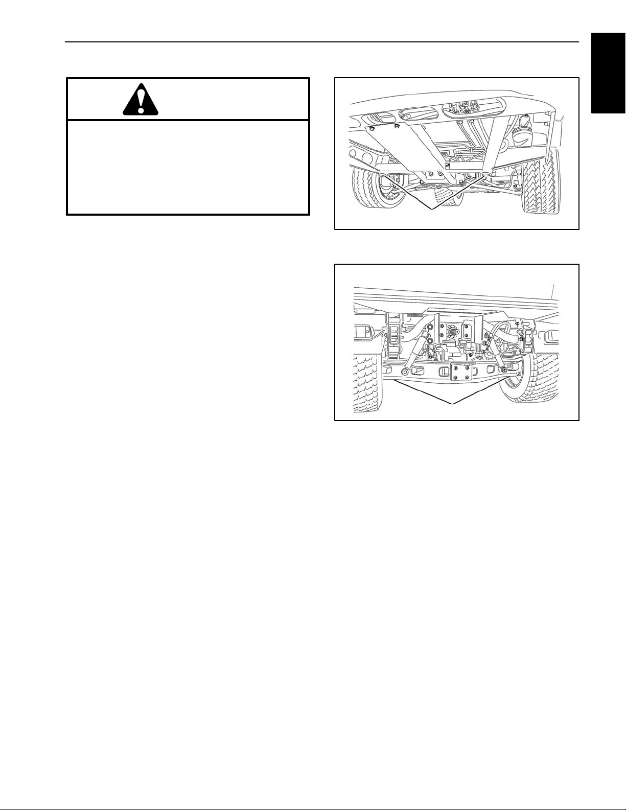
3. The jacking point at the front of the vehicle is under
the front center frame support (Fig. 1). When jacking up
front of vehicle, always place a wood block (or similar
material) between jack and vehicle frame support.
Safety
1
Figure 1
1. Front jacking point
4. The jacking point at the rear of the vehicle is under
the axle tube (Fig. 2).
1
Figure 2
1. Rear jacking point
Workman HD Series
Page 1 − 5
Safety
Page 12
Using Bed Safety Support
Many of the procedures shown in this manual require raising and lowering the bed. The following
precautions must be taken or serious injury or
death could result.
WARNING
Before servicing or making adjustments to the
vehicle, stop engine, engage parking brake and
remove key from ignition switch. Any load material must be removed from bed or other attachment before working under raised bed. Never
work under a raised bed without positioning bed
safety support on a fully extended cylinder rod.
After work is completed, remove bed safety support, insert safety support into storage brackets on
back of ROPS panel and lower bed.
1. Raise bed until lift cylinders are fully extended.
2. Remove bed safety support from storage brackets
on back of ROPS panel.
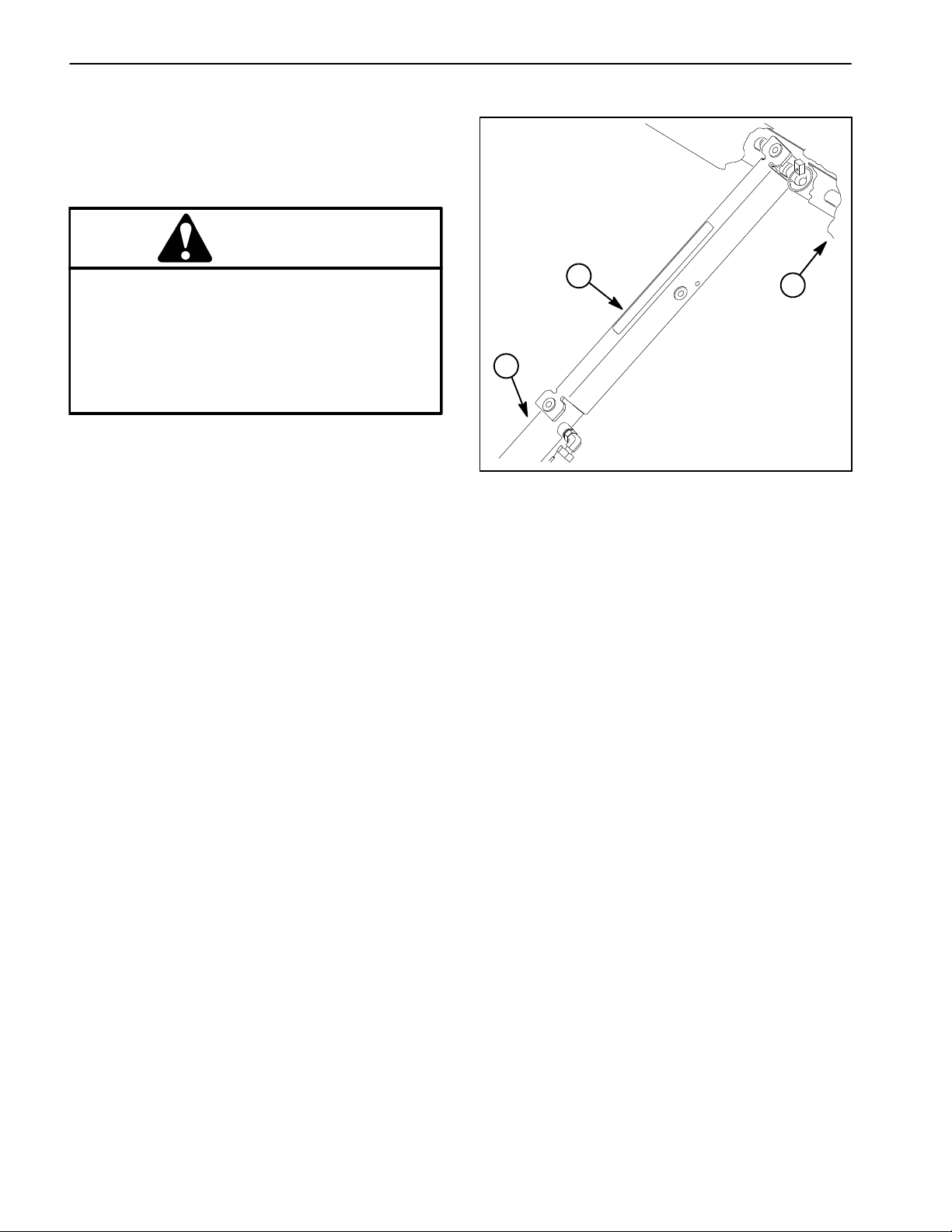
3. Push bed safety support onto cylinder rod, making
sure support end tabs rest on end of cylinder barrel and
on cylinder rod end (Fig. 3).
4. To store bed safety support, remove support from lift
cylinder and insert into storage brackets on back of
ROPS panel.
1
2
1. Bed safety support
2. Cylinder barrel
3
Figure 3
3. Bed
5. Always install or remove bed safety support from
outside of bed.
6. Do not try to lower bed with bed safety support on lift
cylinder: cylinder and bed damage may occur.
Safety and Instruction Decals
Numerous safety and instruction decals are affixed to
the Workman HD vehicle. If any decal becomes illegible
or damaged, install a new decal. Decal descriptions and
part numbers are listed in the vehicle Operator’s Manual
and Parts Catalog.
Safety
Page 1 − 6
Workman HD Series
Page 13

Product Records and Maintenance
Table of Contents
PRODUCT RECORDS 1.........................
MAINTENANCE 1..............................
EQUIVALENTS AND CONVERSIONS 2...........
Decimal and Millimeter Equivalents 2............
U.S. to Metric Conversions 2...................
TORQUE SPECIFICATIONS 3...................
Fastener Identification 3.......................
Using a Torque Wrench with an Offset Wrench 3..
Standard Torque for Dry, Zinc Plated and Steel
Fasteners (Inch Series Fasteners) 4...........
Standard Torque for Dry, Zinc Plated and Steel
Fasteners (Metric Fasteners) 5...............
Other Torque Specifications 6..................
Conversion Factors 6.........................
Chapter 2
Product Records
and Maintenance
Product Records
Insert Operator’s Manual and Parts Catalog for your
Workman HD series vehicle at the end of this chapter.
Refer to Operator’s Manual for recommended maintenance intervals. Additionally, insert Installation Instructions, Operator’s Manuals, Parts Catalogs and Service
Manuals for any accessories that have been installed on
your Workman at the end of this section.
Maintenance
Maintenance procedures and recommended service intervals for the Workman HD series vehicles are covered
in the Operator’s Manual. Refer to that publication when
performing regular equipment maintenance. Several
maintenance procedures have break−in intervals identified in the Operator’s Manual. Refer to the Engine Operator’s Manual for additional engine specific
maintenance procedures.
Workman HD Series Page 2 − 1 Product Records and Maintenance
Page 14
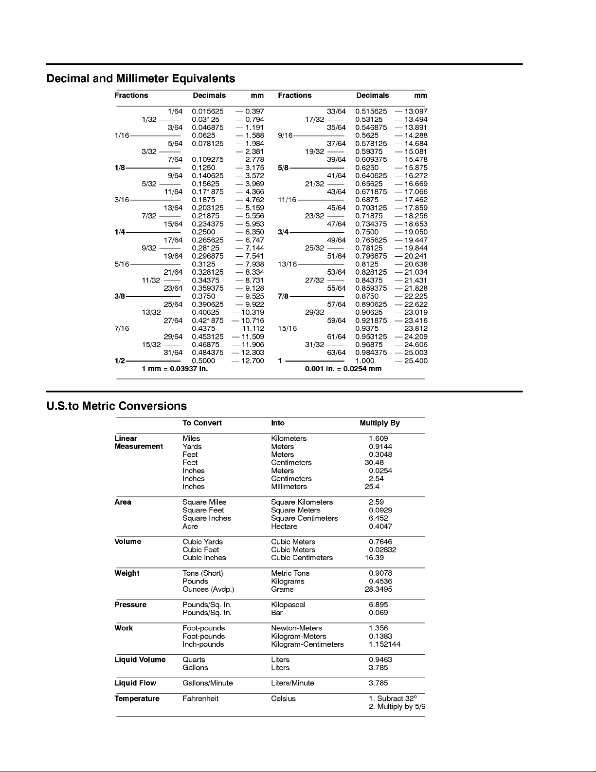
Equivalents and Conversions
0.09375
Workman HD SeriesPage 2 − 2Product Records and Maintenance
Page 15
Torque Specifications
Recommended fastener torque values are listed in the
following tables. For critical applications, as determined
by Toro, either the recommended torque or a torque that
is unique to the application is clearly identified and specified in this Service Manual.
These Torque Specifications for the installation and
tightening of fasteners shall apply to all fasteners which
do not have a specific requirement identified in this Service Manual. The following factors shall be considered
when applying torque: cleanliness of the fastener, use
of a thread sealant (e.g. Loctite), degree of lubrication
on the fastener, presence of a prevailing torque feature
(e.g. Nylock nut), hardness of the surface underneath
the fastener’s head or similar condition which affects the
installation.
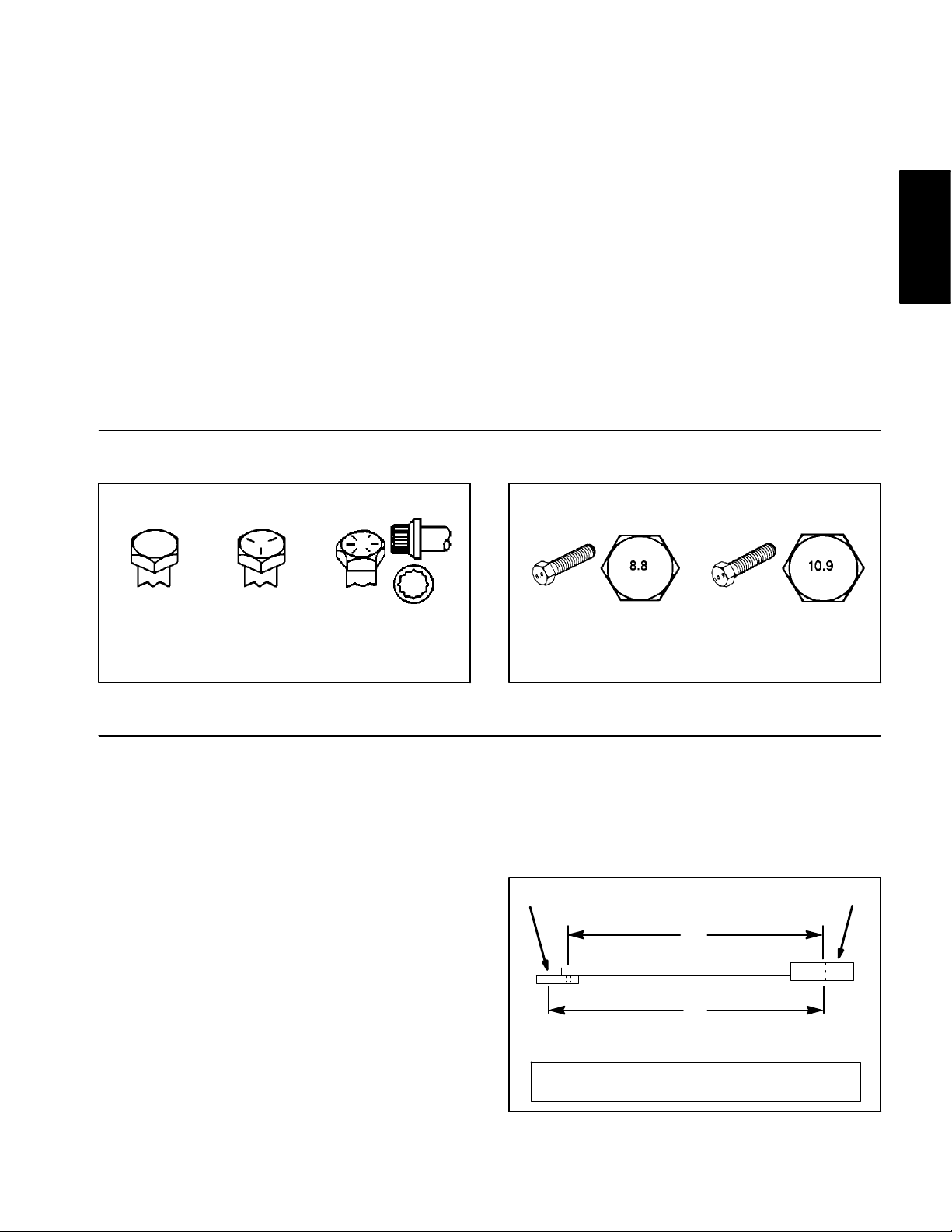
Fastener Identification
As noted in the following tables, torque values should be
reduced by 25% for lubricated fasteners to achieve
the similar stress as a dry fastener. Torque values may
also have to be reduced when the fastener is threaded
into aluminum or brass. The specific torque value
should be determined based on the aluminum or brass
material strength, fastener size, length of thread engagement, etc.
The standard method of verifying torque shall be performed by marking a line on the fastener (head or nut)
and mating part, then back off fastener 1/4 of a turn.
Measure the torque required to tighten the fastener until
the lines match up.
Product Records
and Maintenance
Grade 1 Grade 5 Grade 8
Inch Series Bolts and Screws
Figure 1
Using a Torque Wrench with an Offset Wrench
Use of an o f fset wrench (e.g. crowfoot wrench) will affect
torque wrench calibration due to the effective change of
torque wrench length. When using a torque wrench with
an offset wrench, multiply the listed torque recommendation by the calculated torque conversion factor (Fig.
3) to determine proper tightening torque. Tightening
torque when using a torque wrench with an offset
wrench will be lower than the listed torque recommendation.
Example: The measured effective length of the torque
wrench (distance from the center of the handle to the
center of the square drive) is 18”.
The measured effective length of the torque wrench with
the offset wrench installed (distance from the center of
the handle to the center of the offset wrench) is 19”.
Class 8.8 Class 10.9
Metric Bolts and Screws
Figure 2
If the listed torque recommendation for a fastener is
from 76 to 94 ft−lb, the proper torque when using this
torque wrench with an offset wrench would be from 72
to 89 ft−lb.
(effective length of
torque wrench)
A
B
(effective length of torque
wrench + offset wrench)
TORQUE CONVERSION FACTOR = A / B
Torque wrenchOffset wrench
The calculated torque conversion factor for this torque
wrench with this offset wrench would be 18 / 19 = 0.947.
Workman HD Series Page 2 − 3 Product Records and Maintenance
Figure 3
Page 16

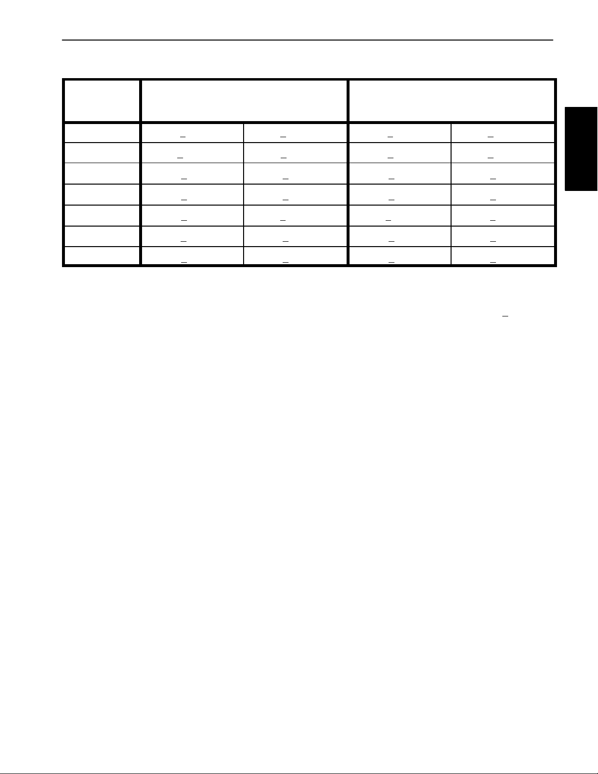
Standard Torque for Dry, Zinc Plated and Steel Fasteners (Inch Series Fasteners)
Thread Size
# 6 − 32 UNC
# 6 − 40 UNF 17 + 2 192 + 23 25 + 3 282 + 34
# 8 − 32 UNC
# 8 − 36 UNF 31 + 4 350 + 45 43 + 5 486 + 56
# 10 − 24 UNC
# 10 − 32 UNF 48 + 5 542 + 56 68 + 7 768 + 79
1/4 − 20 UNC 48 + 7 53 + 7 599 + 79 100 + 10 1130 + 113 140 + 15 1582 + 169
1/4 − 28 UNF 53 + 7 65 + 10 734 + 113 115 + 12 1299 + 136 160 + 17 1808 + 192
5/16 − 18 UNC 115 + 15 105 + 15 1186 + 169 200 + 25 2260 + 282 300 + 30 3390 + 339
5/16 − 24 UNF 138 + 17 128 + 17 1446 + 192 225 + 25 2542 + 282 325 + 33 3672 + 373
3/8 − 16 UNC 16 + 2 16 + 2 22 + 3 30 + 3 41 + 4 43 + 5 58 + 7
Grade 1, 5 &
8 with Thin
Height Nuts
in−lb in−lb N−cm in−lb N−cm in−lb N−cm
10 + 2 13 + 2 147 + 23
13 + 2 25 + 5 282 + 30
18 + 2 30 + 5 339 + 56
ft−lb ft−lb N−m ft−lb N−m ft−lb N−m
SAE Grade 1 Bolts, Screws, Studs &
Sems with Regular Height Nuts
(SAE J995 Grade 2 or Stronger Nuts)
SAE Grade 5 Bolts, Screws, Studs &
Sems with Regular Height Nuts
(SAE J995 Grade 2 or Stronger Nuts)
15 + 2 169 + 23 23 + 3 262 + 34
29 + 3 328 + 34 41 + 5 463 + 56
42 + 5 475 + 56 60 + 6 678 + 68
SAE Grade 8 Bolts, Screws, Studs &
Sems with Regular Height Nuts
(SAE J995 Grade 5 or Stronger Nuts)
3/8 − 24 UNF 17 + 2 18 + 2 24 + 3 35 + 4 47 + 5 50 + 6 68 + 8
7/16 − 14 UNC 27 + 3 27 + 3 37 + 4 50 + 5 68 + 7 70 + 7 95 + 9
7/16 − 20 UNF 29 + 3 29 + 3 39 + 4 55 + 6 75 + 8 77 + 8 104 + 11
1/2 − 13 UNC 30 + 3 48 + 7 65 + 9 75 + 8 102 + 11 105 + 11 142 + 15
1/2 − 20 UNF 32 + 4 53 + 7 72 + 9 85 + 9 115 + 12 120 + 12 163 + 16
5/8 − 11 UNC 65 + 10 88 + 12 119 + 16 150 + 15 203 + 20 210 + 21 285 + 28
5/8 − 18 UNF 75 + 10 95 + 15 129 + 20 170 + 18 230 + 24 240 + 24 325 + 33
3/4 − 10 UNC 93 + 12 140 + 20 190 + 27 265 + 27 359 + 37 375 + 38 508 + 52
3/4 − 16 UNF 115 + 15 165 + 25 224 + 34 300 + 30 407 + 41 420 + 43 569 + 58
7/8 − 9 UNC 140 + 20 225 + 25 305 + 34 430 + 45 583 + 61 600 + 60 813 + 81
7/8 − 14 UNF 155 + 25 260 + 30 353 + 41 475 + 48 644 + 65 667 + 66 904 + 89
NOTE: Reduce torque values listed in the table above
by 25% for lubricated fasteners. Lubricated fasteners
are defined as threads coated with a lubricant such as
engine oil or thread sealant such as Loctite.
NOTE: The nominal torque values listed above for
Grade 5 and 8 fasteners are based on 75% of the minimum proof load specified in SAE J429. The tolerance is
approximately +
10% of the nominal torque value. Thin
height nuts include jam nuts.
NOTE: Torque values may have to be reduced when
installing fasteners into threaded aluminum or brass.
The specific torque value should be determined based
on the fastener size, the aluminum or base material
strength, length of thread engagement, etc.
Workman HD SeriesPage 2 − 4Product Records and Maintenance
Page 17
Standard Torque for Dry, Zinc Plated and Steel Fasteners (Metric Fasteners)
Class 8.8 Bolts, Screws and Studs with
Thread Size
M5 X 0.8 57 + 6 in−lb 644 + 68 N−cm 78 + 8 in−lb 881 + 90 N−cm
M6 X 1.0 96 + 10 in−lb 1085 + 113 N−cm 133 + 14 in−lb 1503 + 158 N−cm
M8 X 1.25 19 + 2 ft−lb 26 + 3 N−m 28 + 3 ft−lb 38 + 4 N−m
M10 X 1.5 38 + 4 ft−lb 52 + 5 N−m 54 + 6 ft−lb 73 + 8 N−m
M12 X 1.75 66 + 7 ft−lb 90 + 10 N−m 93 + 10 ft−lb 126 + 14 N−m
M16 X 2.0 166 + 17 ft−lb 225 + 23 N−m 229 + 23 ft−lb 310 + 31 N−m
M20 X 2.5 325 + 33 ft−lb 440 + 45 N−m 450 + 46 ft−lb 610 + 62 N−m
NOTE: Reduce torque values listed in the table above
by 25% for lubricated fasteners. Lubricated fasteners
are defined as threads coated with a lubricant such as
engine oil or thread sealant such as Loctite.
NOTE: Torque values may have to be reduced when
installing fasteners into threaded aluminum or brass.
The specific torque value should be determined based
on the fastener size, the aluminum or base material
strength, length of thread engagement, etc.
Regular Height Nuts
(Class 8 or Stronger Nuts)
NOTE: The nominal torque values listed above are
based on 75% of the minimum proof load specified in
SAE J1199. The tolerance is approximately +
nominal torque value.
Class 10.9 Bolts, Screws and Studs with
Regular Height Nuts
(Class 10 or Stronger Nuts)
10% of the
Product Records
and Maintenance
Workman HD Series Page 2 − 5 Product Records and Maintenance
Page 18
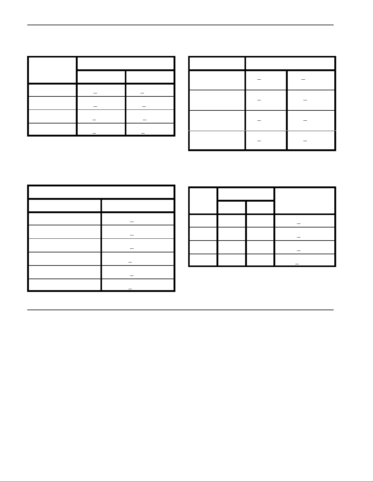
Other Torque Specifications
SAE Grade 8 Steel Set Screws
Recommended Torque
Thread Size
Square Head Hex Socket
1/4 − 20 UNC 140 + 20 in−lb 73 + 12 in−lb
5/16 − 18 UNC 215 + 35 in−lb 145 + 20 in−lb
3/8 − 16 UNC 35 + 10 ft−lb 18 + 3 ft−lb
1/2 − 13 UNC 75 + 15 ft−lb 50 + 10 ft−lb
Thread Cutting Screws
(Zinc Plated Steel)
Type 1, Type 23 or Type F
Thread Size Baseline Torque*
No. 6 − 32 UNC 20 + 5 in−lb
Wheel Bolts and Lug Nuts
Thread Size
7/16 − 20 UNF
Grade 5
1/2 − 20 UNF
Grade 5
M12 X 1.25
Class 8.8
M12 X 1.5
Class 8.8
** For steel wheels and non−lubricated fasteners.
Thread Cutting Screws
(Zinc Plated Steel)
Thread
Size
No. 6 18 20 20 + 5 in−lb
Threads per Inch
Type A Type B
Recommended Torque**
65 + 10 ft−lb 88 + 14 N−m
80 + 10 ft−lb 108 + 14 N−m
80 + 10 ft−lb 108 + 14 N−m
80 + 10 ft−lb 108 + 14 N−m
Baseline Torque*
No. 8 − 32 UNC 30 + 5 in−lb
No. 10 − 24 UNC 38 + 7 in−lb
1/4 − 20 UNC 85 + 15 in−lb
5/16 − 18 UNC 110 + 20 in−lb
3/8 − 16 UNC 200 + 100 in−lb
Conversion Factors
in−lb X 11.2985 = N−cm N−cm X 0.08851 = in−lb
ft−lb X 1.3558 = N−m N−m X 0.7376 = ft−lb
No. 8 15 18 30 + 5 in−lb
No. 10 12 16 38 + 7 in−lb
No. 12 11 14 85 + 15 in−lb
* Hole size, material strength, material thickness and finish must be considered when determining specific
torque values. All torque values are based on non−lubricated fasteners.
Workman HD SeriesPage 2 − 6Product Records and Maintenance
Page 19

Table of Contents
Chapter 3
Kubota EFI Gasoline Engine
SPECIFICATIONS 3............................
GENERAL INFORMATION 4.....................
Introduction 4................................
Operator’s Manual 4..........................
Kubota Workshop and Diagnostics Manuals 3....
Kubota Gasoline Engine 3.....................
Kubota Gasoline Engine
Electronic Control Unit (ECU) 5...............
SERVICE AND REPAIRS 6......................
Air Cleaner System 6..........................
Exhaust System 8............................
Fuel System 10...............................
Fuel Tank 11.................................
Fuel pump 12...............................
Carbon canister 13..........................
Radiator 14..................................
Engine 16....................................
KUBOTA WORKSHOP MANUAL, GASOLINE EN-
GINE, WG972−G−E3F
KUBOTA DIAGNOSTICS MANUAL, GASOLINE EN-
GINE, WG972−G−E3F
Kubuta EFI
Gasoline Engine
Workman HDX Page 3 − 1 Kubota EFI Gasoline Engine
Page 20

This page is intentionally left blank.
Workman HDXPage 3 − 2Kubota EFI Gasoline Engine
Page 21

Specifications
Item Description
Make / Designation Kubota, Vertical, 4−Cycle, 3 Cylinder,
Liquid Cooled, Gasoline Engine
Bore 2.93 in (74.5 mm)
Stroke 2.90 in. (73.6 mm)
Total Displacement 58.68 cu. In. (962 cc)
Compression Ratio 9.2:1
Ignition Timing 31_ BTDC @ 3600 rpm
Ignition System Full Transistor Battery Ignition Type
Firing Order 1−2−3
Spark Plug Type/Gap NGK BKR6E 0.028 to 0.031 in. (0.7 to 0.8 mm)
Intake & Exhaust Valve Clearance (check when engine is cold) 0.0065 + 0.0001 in. (0.165 + 0.02 mm)
Fuel Unleaded Gasoline (up to 10% ethanol)
Fuel Capacity 6.5 Gal (24.6 Ltr)
Governor Electronic
Kubuta EFI
Gasoline Engine
Low Idle (no load) 1100 + 50 RPM
High Idle (no load) 3600 + 50 RPM
Direction of Rotation Counterclockwise (Viewed from Flywheel)
Engine Oil API classification SL or higher
Oil Pump Trochoid Type
Crankcase Oil Capacity 3.5 qt. (3.3 ltr.) with Filter
Starter 12 VDC, 1.2 KW
Alternator/Regulator 12 VDC, 480W
Dry Weight U.S. 163 lbs. (74 Kg)
Coolant Capacity U.S. 3.7 qt. (3.5 ltr.) with 1.0 qt. (0.9 ltr.) Reservoir
(see Vehicle Operator’s Manual for viscosity recommendations)
Workman HDX Page 3 − 3 Kubota EFI Gasoline Engine
Page 22
Introduction
This Chapter gives information about specifications,
maintenance, troubleshooting, testing, and repair of the
Kubota EFI gasoline engine used in the Workman HDX.
Most repairs and adjustments require tools which are
commonly available in many service shops. The use of
some specialized test equipment is explained in the engine service manual included at the end of this chapter.
However, the cost of the test equipment and the specialized nature of some repairs may dictate that the work be
done at an engine repair facility.
Traction Unit Operator’s Manuals
The V ehicle Operator’s Manual provides information regarding the operation, general maintenance and maintenance intervals for your Workman HDX. Refer to this
publication for additional information when servicing the
machine.
Kubota Workshop and Diagnostics Manuals
Service and repair parts for Kubota gasoline engines
are supplied through your local Toro Distributor. If a
parts list is not available, be sure to provide your distributor with the Toro model and serial number.
The engine that powers your Workman HDX is a Kubota
model WG972−G−E3F . Both the Kubota Workshop
Manual and Kubota Diagnostics Manual are available
for this engine. Make sure that the correct engine manuals are used when servicing the engine.
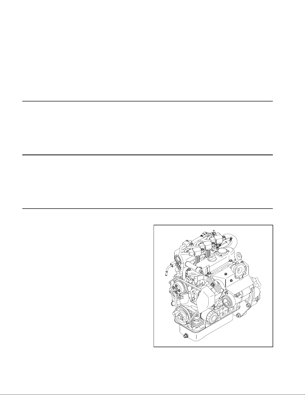
Kubota Gasoline Engine
The engine used in your Workman HDX is a Kubota
WG972 Series gasoline engine. Engine features include an electronic control unit (ECU) that controls a
common rail fuel injection system with direct injection,
electronic throttle valve (ETV), an electronic governor
and a catalytic muffler exhaust system with an oxygen
sensor. The ECU receives information from numerous
engine sensors. The information provided allows the engine ECU to monitor and control engine operation for
optimum engine performance.
Figure 1
Workman HDXPage 3 − 4Kubota EFI Gasoline Engine
Page 23
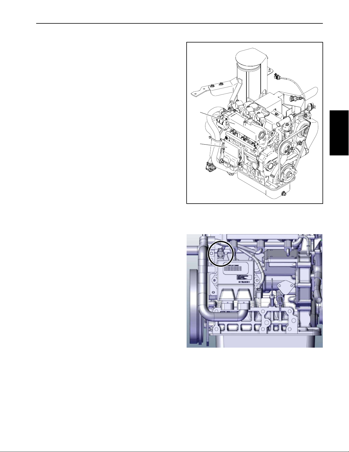
Kubota Gasoline Engine Electronic Control Unit (ECU)
The Kubota gasoline engine that powers your Workman
HDX uses an electronic control unit (ECU) for engine
management. All wire harness electrical connectors
should be plugged into the ECU before the machine ignition switch is moved from the OFF position to either the
ON or START position.
The engine electrical components (e.g. ECU, O2
sensor, throttle control, power relay , ETV relay) are identified and matched in the engine ECU program. If engine
electrical components are replaced on the engine, the
Kubota electronic tool must be used to update the ECU
program which will ensure correct engine operation.
If the engine ECU identifies that an engine problem exists, the check engine light on the Operator’s Control
Panel will illuminate. The engine speed may be reduced
or the engine might stop. The Kubota Gasoline Service
Tool (KGST) and software, and the Kubota Diagnostic
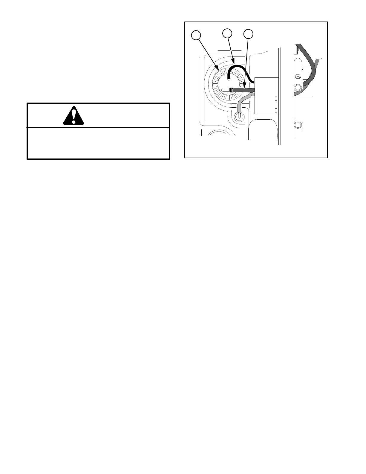
Manual should be used to provide assistance in identifying the cause of the problem and any repairs that are necessary. Connect the Kubota Gasoline Service Tool
(KGST) to the diagnostic connector above the engine
ECU (Fig. 3). Contact your Toro distributor for assistance in Kubota engine troubleshooting.
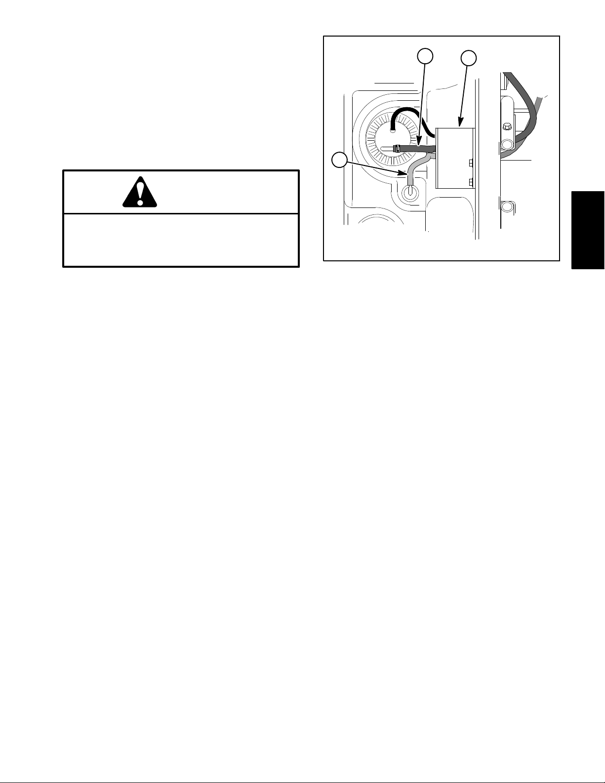
IMPORTANT: Two (2) communication connectors
are located near the engine ECU. The connector
along side of the ECU (near the middle of the engine)
is not used for service diagnostics.
1
2
Kubuta EFI
Gasoline Engine
Figure 2
1. Engine (Model 30809)
2. Engine ECU
Do not plug or unplug the engine ECU for a period
of thirty (30) seconds after the machine key switch
is turned OFF. The ECU may remain energized even
though the ignition switch is OFF.
If the engine ECU is to be disconnected for any reason,
make sure that the ignition switch is in the OFF position
with the key removed before disconnecting the engine
ECU. Also, to prevent possible ECU damage when
welding on the machine, disconnect and remove the engine ECU from the machine before welding.
Figure 3
Diagnostic connector
Workman HDX Page 3 − 5 Kubota EFI Gasoline Engine
Page 24
Service and Repairs
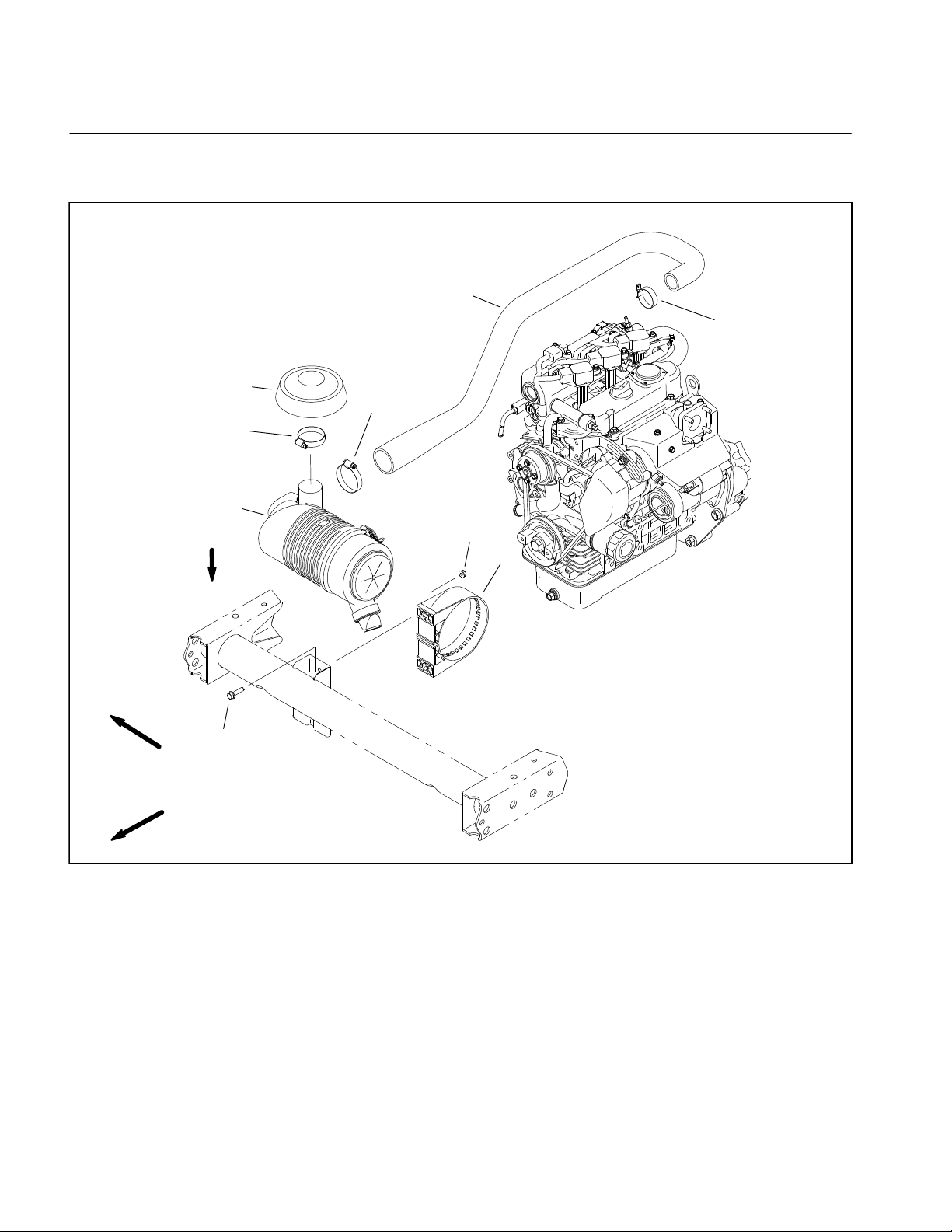
Air Cleaner System
3
2
5
6
4
VACUATOR
DIRECTION
9
RIGHT
FRONT
1. Air cleaner assembly
2. Hose clamp
3. Air inlet hood
1
7
8
Figure 4
4. Hose clamp
5. Air intake hose
6. Hose clamp
7. Flange nut (2)
8. Mounting bracket
9. Flange head screw (2)
Workman HDXPage 3 − 6Kubota EFI Gasoline Engine
Page 25
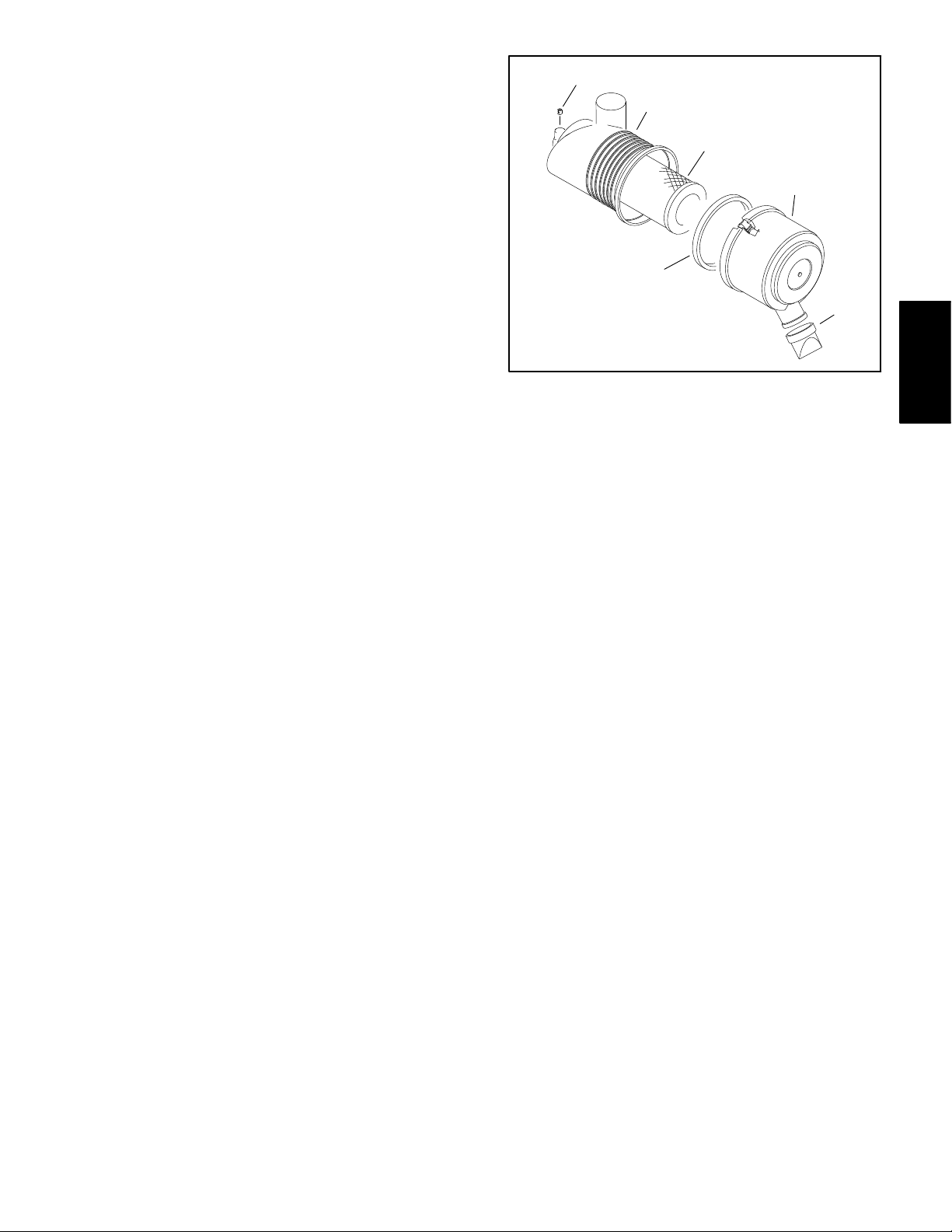
Check Air Filter, Dust Cup, & Burp Valve
The air cleaner body , air filter, dust cup, and burp valve
should be checked daily, prior to operation.
1
2
IMPORTANT: Any leaks in the air cleaner system
will cause serious engine damage. Make sure that
all air cleaner components are in good condition
and are properly secured during operation.
1. Park machine on a level surface, lower cutting units,
stop engine, engage parking brake, and remove key
from the ignition switch. Unlatch and raise hood.
2. Check air cleaner body for damage that could cause
possible air leaks. Make sure cover seals completely to
the air cleaner body (Fig. 5).
3. Check burp valve and dust cup for damage.
4. Make sure air hoses connecting the air cleaner to the
engine and radiator are secured tightly and free of possible air leaks.
Air Cleaner Removal
1. Park vehicle on a level surface and engage parking
brake. Stop the engine and remove key from ignition
switch. Allow engine to cool.
7
1. Plug
2. Body
3. Primary filter element
4. Safety filter element
(if equipped)
3
Figure 6
5. Cover
6. Vacuator valve
7. Gasket (if equipped)
5
6
Kubuta EFI
Gasoline Engine
2. Raise or remove the bed or other attachment(s) if ne cessary . I f bed is raised, place safety support on lift cylinder.
3. Remove air cleaner components as needed.
Air Cleaner Installation
1. Assemble air cleaner system (Fig. 4). Air cleaner inlet hood should be positioned straight upward. The vacuator valve on the air cleaner assembly should be
positioned downward.
2. Lower or install bed or attachment(s).
Workman HDX Page 3 − 7 Kubota EFI Gasoline Engine
Page 26
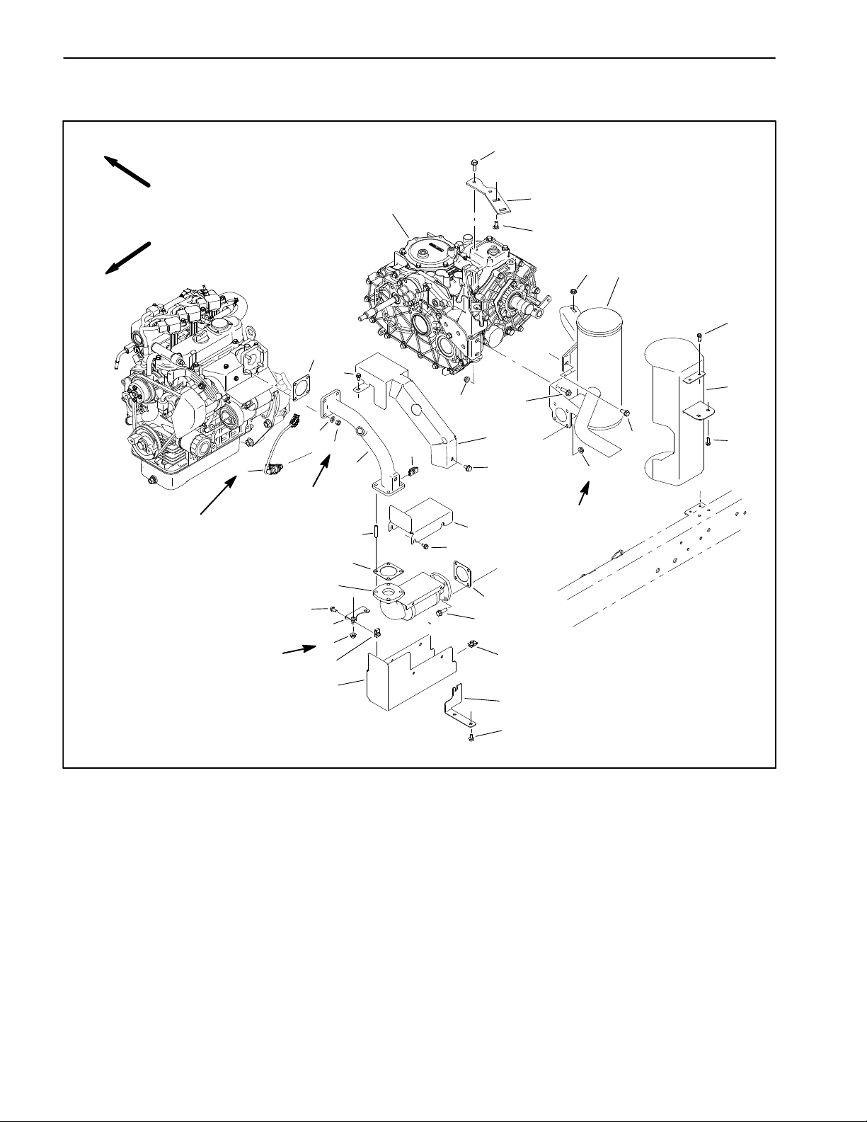
Exhaust System
28
RIGHT
FRONT
28 to 36 ft−lb
(38 to 49 N−m)
1
22 to 26 ft−lb
(30 to 35 N−m)
22 to 26 ft−lb
(30 to 35 N−m)
29
27
26
2520
23
6
13
24
20 21
2
3
17
4
5
16
19
18
10
22 to 26 ft−lb
(30 to 35 N−m)
22
23
15
6
7
8
9
6
14
10
11
11
12
13
1. Oxygen sensor
2. Lock washer (4)
3. Hex nut (4)
4. Exhaust tube
5. Stud (4)
6. Exhaust gasket (3)
7. Catalytic converter
8. Flange head screw
9. Heat shield mount
10. Flange nut (8)
Figure 7
11. Retainer nut (3)
12. Heat shield
13. Heat shield mount
14. Flange head screw (4)
15. Flange head screw (4)
16. Heat shield
17. Retainer nut
18. Flange head screw
19. Heat shield
20. Flange nut (4)
8
21. Flange head screw (2)
22. Flange head screw
23. Flange head screw (4)
24. Heat shield
25. Muffler
26. Carriage bolt (2)
27. Mount plate
28. Flange head screw (2)
29. Transaxle
Workman HDXPage 3 − 8Kubota EFI Gasoline Engine
Page 27

Removal
Installation
1. Park vehicle on a level surface and engage parking
brake. Stop the engine and remove key from ignition
switch. Allow engine to cool.
2. Raise or remove the bed or other attachment(s). If
bed is raised, place safety support on lift cylinder.
3. Note position of exhaust system heat shields and
mounting brackets before removal. Remove exhaust
system components as needed (Fig. 7).
4. Discard gaskets and thoroughly clean flange surfaces of exhaust tube, catalytic converter and muffler.
1. Replace any removed gaskets.
2. Fit all exhaust components to vehicle before tightening any fasteners (Fig. 7). When securing exhaust, tighten fasteners in the following order:
A. Hex nuts that secure exhaust tube to engine.
Torque from 22−26 ft−lbs (30 to 35 N−m).
B. Hex nuts that secure catalytic converter to exhaust tube. Torque from 22−26 ft−lbs (30 to 35
N−m).
C. Flange head screws and flange nuts that secure
muffler to catalytic converter. Torque from 22−26 ft−
lbs (30 to 35 N−m).
D. Flange head screw that secures muffler to transaxle.
E. Flange head screws and flange nuts that secure
muffler to shift cable mount bracket.
F. Carriage bolts and flange nuts that secure muffler
to mount plate.
Kubuta EFI
Gasoline Engine
3. Install all exhaust system heat shields.
NOTE: If oxygen sensor was removed, torque sensor
from 28 to 36 ft−lb (38 to 49 N−m).
4. Lower or install bed or attachment(s).
Workman HDX Page 3 − 9 Kubota EFI Gasoline Engine
Page 28
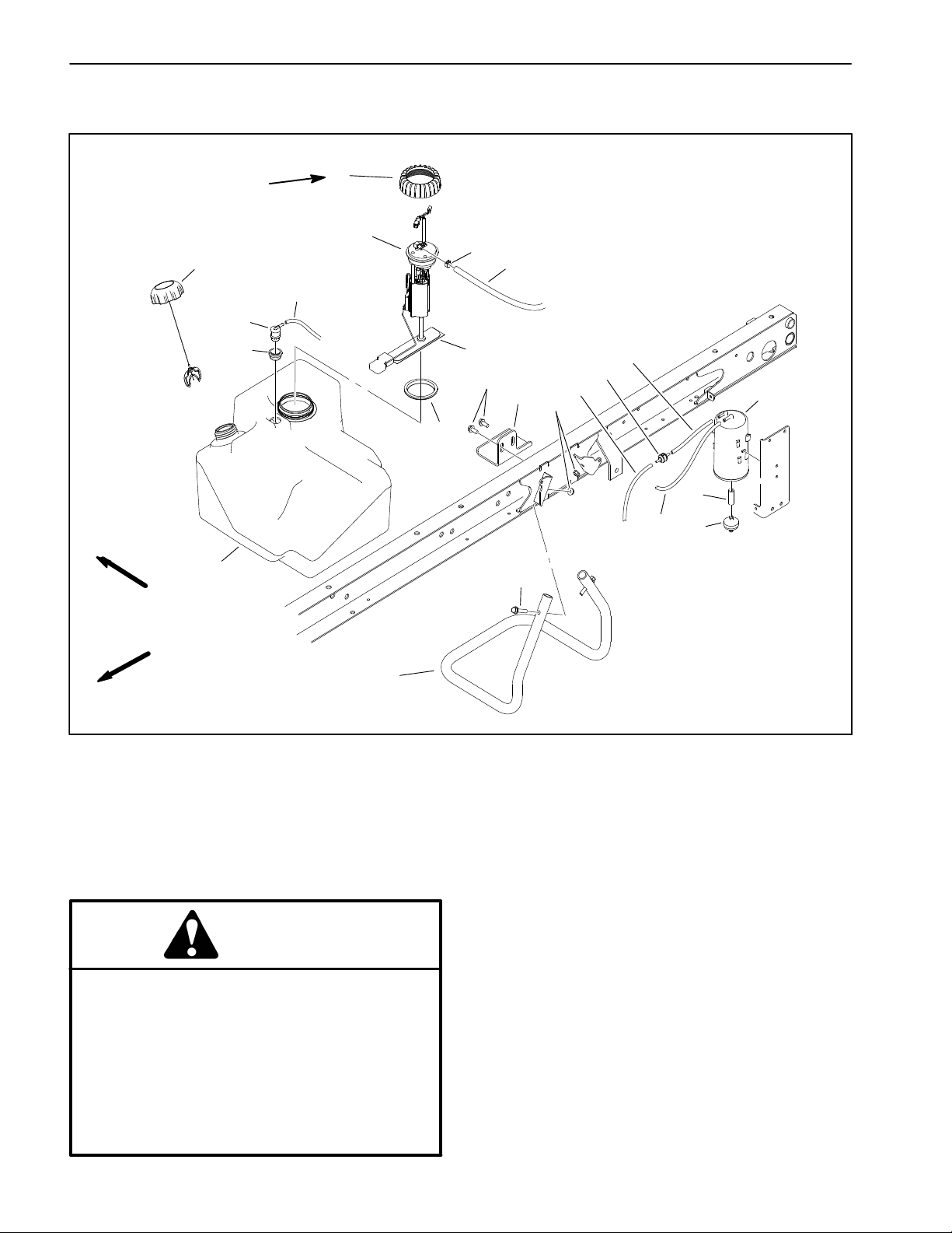
Fuel System
l
RIGHT
175 to 200 in−lb
(20 to 22 N−m)
11
17
18
10
20
12
8
21
22
2
1
TO
ENGINE
3
19
15
16
9
5
4
TO
PURGE
PORT
13
6
8
7
FRONT
14
1. Fuel hose (to engine)
2. Hose clamp
3. Fuel hose (to vacuum valve)
4. Vacuum check valve
5. Fuel hose (to engine)
6. Filter hose
7. Canister filter
8. Fuel hose (tank to canister)
9. Flange nut (2)
10. Fuel tank
11. Fuel cap
12. Fuel pump/sender assembly
13. Carbon cannister
14. Support tube
15. Retainer plate
DANGER
Because gasoline is highly flammable, use caution when storing or handling it. Do not smoke
while filling or servicing the fuel tank. Do not fill
or service fuel tank while engine is running, hot
or when vehicle is in an enclosed area. Always fil
fuel tank outside and wipe up any spilled fuel before starting the engine. Store fuel in a clean,
safety−approved container and keep cap in
place. Use fuel for the engine only; not for any
other purpose.
Figure 8
16. Washer head screw (2)
17. Rollover valve
18. Grommet
19. Washer head screw (2)
20. Cap
21. Gasket
22. Fuel filter
Check Fuel Lines and Connections
Check fuel lines and connections periodically as recommended in the O p e r a t o r’s Manual. Check lines for deterioration, damage, leaks or loose connections. Replace
hoses, clamps and connections as necessary.
Workman HDXPage 3 − 10Kubota EFI Gasoline Engine
Page 29
Fuel Tank Removal (Fig. 8)
1. Park vehicle on a level surface and engage parking
brake. Stop the engine and remove key from ignition
switch. Allow engine to cool.
2. Raise or remove the bed or other attachment(s). If
bed is raised, place safety support on lift cylinder.
3. Disconnect wire harness connectors from fuel pump
and sender on fuel tank.
CAUTION
The fuel supply hose will contain pressurized
fuel. Be careful when disconnecting supply
hose. Wipe up any spilled fuel before starting the
engine.
4. Note routing of fuel hoses for installation purposes
(Fig. 9). Disconnect fuel supply hose from fuel pump/
sender and tank vent hose from rollover valve. Plug fuel
hoses to prevent leakage or system contamination.
3
1. Retainer plate
2. Fuel supply hose
2
Figure 9
1
Kubuta EFI
Gasoline Engine
3. Tank vent hose
5. Remove washer head screws and retainer plate that
secure fuel tank.
6. Remove fuel tank from vehicle.
Fuel Tank Installation (Fig. 8)
1. Position fuel tank to support tube on vehicle.
2. Remove plugs placed in fuel hoses during fuel tank
removal. Connect fuel supply hose to fuel pump/sender
and tank vent hose to rollover valve (Fig. 9). Secure fuel
hoses with hose clamps.
3. Connect wire harness connectors to fuel pump and
sender.
4. Position retainer plate to tank and frame. Make sure
that fuel hoses are correctly placed under plate (Fig. 9).
While pressing down on retainer plate to best retain
tank, install and tighten washer head screws to secure
fuel tank.
5. Lower or install the bed or other attachment(s).
6. Fill fuel tank. Check for fuel leakage and correct if
found.
Workman HDX Page 3 − 11 Kubota EFI Gasoline Engine
Page 30
Fuel Pump Removal (Fig. 8)
1. Park vehicle on a level surface, raise bed and engage parking brake. Stop the engine and remove key
from ignition switch. Allow engine to cool.
2. Install bed support on bed lift cylinder to prevent bed
from lowering.
3. Disconnect vehicle wire harness connectors from
fuel pump/sender assembly on fuel tank.
CAUTION
The fuel supply hose will contain pressurized
fuel. Be careful when disconnecting fuel supply
hose. Wipe up any spilled fuel before starting the
engine.
4. Disconnect fuel supply hose from fuel pump/sender.
Plug fuel hose to prevent leakage or system contamination.
1
1. Fuel pump/sender
2. Wire harness
2
3
Figure 10
3. Fuel supply hose
5. Note orientation of fuel fitting on fuel pump for assembly purposes.
6. Remove cap that secures fuel pump/sender assembly in fuel tank.
NOTE: Do not allow fuel pump/sender assembly to rotate during removal or damage to the sender float arm
may result.
7. Carefully remove fuel pump/sender and gasket from
tank.
Fuel Pump Installation (Fig. 8)
1. Make sure that fuel tank and fuel pump/sender gasket surfaces are thoroughly clean.
2. Position gasket to sealing surface of fuel pump/
sender.
3. Carefully insert fuel pump/sender and gasket into
tank. Orientate fuel fitting so that it is pointing toward the
vehicle frame.
4. Secure fuel pump/sender to fuel tank with cap.
Torque cap from 175 to 200 in−lb (20 to 22 N−m).
5. Remove plug placed in fuel supply hose and connect
supply hose to fuel pump/sender. Secure fuel hose with
hose clamp.
6. Connect vehicle wire harness connectors to fuel
pump/sender assembly on fuel tank.
7. Remove bed support from lift cylinder and lower bed.
Workman HDXPage 3 − 12Kubota EFI Gasoline Engine
Page 31

Carbon Canister
The function of the fuel evaporative control system is to
collect and store evaporative emissions from the fuel
tank and engine. A carbon canister that is mounted to
the left side of the frame is used to collect these evaporative emissions. Fuel vapors from the engine and fuel
tank are vented to the canister when the engine is not
running. Vapors from the canister are consumed when
the engine is running.
NOTE: If there is restriction in the canister breather, the
carbon canister or the vacuum check valve, the fuel tank
may distort due to venting issues. If the fuel tank returns
to it’s normal shape when the fuel cap is removed, restriction in the evaporative control system is likely.
Carbon Canister Removal
1. Park vehicle on a level surface, raise bed and engage parking brake. Stop the engine and remove key
from ignition switch. Allow engine to cool.
DANGER
2
3
4
TO
FUEL
TANK
TO
PURGE
PORT
AT ENGINE
1. Carbon canister
2. Fuel hose
3. Vacuum check valve
4. Fuel hose (to engine)
1
5
6
7
Figure 11
5. Fuel hose (to tank)
6. Filter hose
7. Canister filter
8. Canister mount
8
Kubuta EFI
Gasoline Engine
Gasoline is flammable. Use caution when storing
or handling it. Do not smoke while filling the fuel
tank. Do not fill fuel tank while engine is running
or in an enclosed area. Always fill fuel tank outside and wipe up any spilled fuel before starting
the engine. Store fuel in a clean, safety−approved container and keep the cap in place. Use
gasoline for the engine only; not for any other
purpose.
2. Inspect carbon cannister and attached hoses for
damage or obvious leaks. A damaged or leaking cannister should be replaced.
3. Note hose routing, cable tie and anchor clamp locations. Remove fuel evaporative control system components as needed (Fig. 11).
Carbon Canister Installation
1. Install all removed EVAP components. Make sure
that fuel hoses are not kinked after installation. Secure
all hoses with hose clamps, anchor clamps and cable
ties as noted. If hoses were removed from the carbon
canister, check hose connections for correct system operation (Fig. 11).
2. After all evaporative control system components are
installed, remove bed support from lift cylinder and l o w er bed.
Workman HDX Page 3 − 13 Kubota EFI Gasoline Engine
Page 32

Radiator
4
3
9
1
RIGHT
5
6
7
8
10
11
12
2
28
7
23
14
17
15
Thread Sealant
25
26
24
17
22
17
14
8
7
21
15
16
15
5
15
17
19
18
12
17
20
27
13
29
FRONT
Thread
Sealant
7
18
30
1. Radiator guard (industrial)
2. Radiator screen
3. Swell latch (4)
4. Flange head screw
(4 − industrial)
5. Flange head screw (4)
6. Flat Washer
7. Hose clamp
8. Hose (radiator to reservoir)
9. Flange head screw
(2 − industrial)
Figure 12
10. Clip (2)
11. Radiator mount
12. Hose (lower hose to reservoir)
13. Flange nut (4 − industrial)
14. Cable tie
15. Flange nut (4)
16. Upper radiator hose
17. Hose clamp (6)
18. Hose (engine to reservoir)
19. R−clamp (2)
20. Lower radiator hose
21. Tee fitting
22. Lower radiator hose
23. Flange nut (2)
24. Reservoir cap
25. Coolant reservoir
26. Reservoir mount
27. Flange head screw (2)
28. Oil cooler (optional)
29. Barb fitting
30. Temperature sensor
Workman HDXPage 3 − 14Kubota EFI Gasoline Engine
Page 33

Removal (Fig. 12)
Installation (Fig. 12)
1. Park vehicle on a level surface, stop engine, engage
parking brake and remove key from the ignition switch.
Allow engine and radiator to cool.
2. Raise or remove the bed or other attachment(s). If
bed is raised, place safety support on lift cylinder.
3. Unlatch and remove radiator screen from front of radiator.
4. If vehicle is equipped with high flow hydraulics kit, rotate oil cooler latches and place oil cooler away from radiator.
CAUTION
Do not open radiator cap or drain coolant if the
radiator or engine is hot. Pressurized, hot coolant can escape and cause burns.
Ethylene−glycol antifreeze is poisonous. Dispose of coolant properly or store it in a properly
labeled container away from children and pets.
1. If radiator assembly was disassembled, install components to radiator using (Fig. 13) as a guide. Make sure
that clearance exists between shroud and fan at all
points.
2. Remove plugs from radiator openings and hoses
placed during the removal procedure.
3. Position radiator assembly to the radiator mount. Secure radiator assembly to the vehicle with removed
flange head screws, flat washers and flange nuts.
4. Connect reservoir hose to the radiator filler neck. Secure hose with hose clamp.
5. Connect upper and lower hoses to the radiator. Secure hoses with hose clamps.
6. Connect wire harness connector to radiator fan.
7. Fill radiator with coolant to the bottom of the filler
neck.
8. If vehicle is equipped with high flow hydraulics kit,
position oil cooler to radiator and secure in place.
Kubuta EFI
Gasoline Engine
5. Remove the radiator cap.
6. Drain radiator into a suitable container by disconnecting lower radiator hose from the radiator.
7. Disconnect upper radiator hose from the radiator.
8. Disconnect reservoir hose from the radiator filler
neck.
9. Disconnect wire harness connector from radiator
fan.
10.Detach radiator assembly from radiator mount:
A. Remove two (2) flange head screws and flat
washers that secure the top of the radiator assembly
to the mount.
B. Remove two (2) flange head screws and flange
nuts that secure the bottom of the radiator assembly
to the mount.
11.Carefully separate radiator assembly from mount
and remove from vehicle.
12.Plug all radiator and hose openings to prevent con-
tamination.
9. Install and latch the radiator screen.
10.Lower or install bed or other attachment(s).
6
1
5
7
2
4
9
8
3
6
Figure 13
1. Radiator
2. Electric fan
3. Shroud
4. Latch (2 − oil cooler)
5. Flange screw (7)
6. Nut (7)
7. Screw (4)
8. Lower mount plate
9. Radiator cap
5
13.If necessary, remove components from radiator (Fig.
13).
Workman HDX Page 3 − 15 Kubota EFI Gasoline Engine
Page 34

Engine
RIGHT
FRONT
26
25
27
28
23
29
23
24
15 to 20 ft−lb
(20 to 27 N−m)
22
18
14
13
16
15
12
21
11
10
9
8
16
7
ANTI−SEIZE
6
1
2
LUBRICANT
14
20
19
17
LOCTITE #242
15 to 20 ft−lb
(20 to 27 N−m)
3
4
5
1. Gear pump
2. O−ring
3. Hydraulic fitting
4. Hose clamp
5. Suction hose (from transaxle)
6. O−ring
7. Hose (to lift valve)
8. O−ring
9. Hydraulic fitting
10. Flange nut (4)
Figure 14
11. Square key
12. Pump/engine mount
13. Flange head screw (4)
14. Flange head screw (8)
15. Hex head screw (2)
16. Square head screw (2)
17. Pump hub
18. Coupling
19. Hex head screw (2)
20. Flat washer (2)
21. Hex flange nut (2)
22. Lower radiator hose
23. Hose clamp
24. Fuel supply hose
25. Upper radiator hose
26. Air intake hose
27. Hose clamp
28. Return fuel hose
29. Exhaust tube
Workman HDXPage 3 − 16Kubota EFI Gasoline Engine
Page 35

Engine Removal (Fig. 14)
1. Park vehicle on a level surface and engage parking
brake. Stop the engine and remove key from ignition
switch. Allow engine to cool.
2. Raise or remove the bed or other attachment(s) to
gain acces s t o e ngine. If bed is raised, place safety support on lift cylinder.
3. Disconnect negative (−) and then positive (+) battery
cables at the battery.
4. Remove exhaust tube from vehicle (see Exhaust
System Removal in this section).
5. Loosen hose clamp that secures air intake hose to
engine. Remove intake hose from engine.
6. Disconnect fuel supply and return hoses from fuel in-
jection pump on engine. Plug end of fuel hoses to prevent contamination and fuel spillage. Position
disconnected fuel hoses away from engine.
7. Note location of cable ties used to secure wire har-
ness leads. Label and disconnect wire harness connectors that attach to engine:
1. Engine
2. Positive cable
3. Fusible link harness
4. Lock washer
7
6
Figure 15
5. Hex nut
6. Flange head screw
7. Negative/ground cable
1
2
3
4
5
Kubuta EFI
Gasoline Engine
A. Positive (+) battery cable, fusible link harness
and harness ring terminal from starter solenoid stud
(Fig. 12).
B. Wire from spade terminal on starter solenoid.
C. Wire from oil pressure switch.
D. Wires from temperature sender and thermal fan
switch on water pump housing.
E. Harness connector and wire with ring terminal
from alternator.
F. Negative (−) battery cable and harness ground
connector secured to engine mount (Fig. 15). Note
location of ground connections and flange head
screw for assembly purposes.
G. Harness connector with ring terminal from glow
plug connector.
H. Harness connector from fuel solenoid on injection pump.
I. Harness connector from crankshaft sensor.
8. Disconnect accelerator cable from throttle lever and
cable support bracket. Position accelerator cable away
from engine.
1
5
8
1. Cap screw
2. Flange nut
3. R−clamp
4. Engine support
5. Engine mount
Figure 16
6. Snubbing washer
7. Engine mount assembly
8. Engine support
9. Flange nut (8)
10. Flange head screw (8)
1
3
70 to 80 ft−lb
(95 to 108 N−m)
6
7
9
7
6
2
10
Workman HDX Page 3 − 17 Kubota EFI Gasoline Engine
Page 36

CAUTION
Do not open radiator cap or drain coolant if the
radiator or engine is hot. Pressurized, hot coolant can escape and cause burns.
Ethylene−glycol antifreeze is poisonous. Dispose of coolant properly or store it in a properly
labeled container away from children and pets.
9. Remove the radiator cap. Drain radiator into a suitable container by disconnecting lower radiator hose
from the radiator.
10.Loosen hose clamps and remove upper and lower
radiator hoses from engine. Remove R−clamp that secures lower radiator hose to engine mount. Position radiator hoses away from engine.
11.Remove all clamps and cable ties used to attach wiring harness, hoses or cables to the engine.
12.On 4WD vehicles, remove differential drive shaft
(see Dif ferential Driveshaft in Chapter 10 − Front Wheel
Drive (4WD)).
17.Use engine lifting lugs provided and a hoist or lift to
remove engine from chassis. One person should operate hoist or lift and a second person should help guide
engine out of chassis. Move engine forward before lifting to disengage transaxle input shaft from clutch.
18.Note location and retrieve two (2) dowel pins from
bell housing (Fig. 17).
19.If necessary , remove gear pump from engine mount
(see Gear Pump Removal in Chapter 9 − Hydraulic System).
20.If necessary, remove engine mount from engine.
21.If necessary, remove coupler components from engine pulley.
22.If necessary, remove pressure plate and clutch disc
(see Clutch Disassembly and Inspection in Chapter 6 −
Drive Train).
2
5
3
4
1
CAUTION
Before performing any service or repair on hydraulic system components, relieve system
pressure to avoid injury from pressurized hydraulic oil. Rotate the steering wheel in both directions, make sure that the bed is lowered onto
the bed support and operate any other hydraulic
accessories.
13.Thoroughly clean junction of gear pump fittings and
hydraulic hoses. Label hydraulic hoses for assembly
purposes. Disconnect hydraulic hoses from gear pump.
Install caps or plugs in hoses and pump fittings to prevent contamination and leakage of hydraulic oil.
14.Put blocking under transaxle to prevent the transaxle
from moving during engine removal.
15.Loosen and remove two (2) flange nuts, snubbing
washers and cap screws that secure engine mounts to
engine support (Fig. 16).
16.Remove six (6) cap screws that secure clutch bell
housing to engine. Note location of harness bracket(s)
(Fig. 17).
4
1. Bell housing
2. Cap screw (6)
3. Harness bracket
2
3
2
Figure 17
4. Dowel pins (2)
5. Harness bracket
Workman HDXPage 3 − 18Kubota EFI Gasoline Engine
Page 37

Engine Installation (Fig. 14)
1. Install pressure plate and clutch disc if removed (see
Installing Clutch Disc and Cover in Chapter 6 − Drive
Train).
2. If coupler assembly was removed, assemble coupler
to engine pulley. Apply Loctite #242 (or equivalent) to
threads of flange head screws that secure coupler to engine pulley. Torque fasteners to 15 to 20 ft−lb (20 to 27
N−m).
3. If engine mount was removed, secure mount to en-
gine with seven (7) flange head screws. Do not install
the screw used to secure the ground connections to the
engine at this time.
4. If gear pump was removed, install gear pump to en-
gine mount (see Gear Pump Installation in Chapter 9 −
Hydraulic System in this manual).
5. Install two (2) dowel pins in bell housing bores (Fig.
14).
6. Make sure that snubbing washer is positioned on top
of both engine mounts (Fig. 13).
7. Apply anti−seize lubricant to splines on transaxle in-
put shaft.
8. Use engine lifting lugs provided and a hoist or lift to
install engine to chassis. One person should operate
hoist and second person should help guide engine to
machine. Align splines on transaxle input shaft and
clutch while moving engine to bell housing on transaxle.
9. Secure bell housing to engine with six (6) cap screws
and harness bracket(s) (Fig. 17).
10.Secure engine mount to engine support with two (2)
cap screws, snubbing washers and flange nuts (Fig.
16).
11.Remove plugs from hydraulic hoses and gear pump
fittings. Connect hydraulic hoses to gear pump (see Hydraulic Hose and Tube Installation in Chapter 9 − Hydraulic System).
14.Fill radiator with coolant (see vehicle Operator’s
Manual).
15.Connect wire harness connectors to engine components. Secure wire harness to machine with cable ties
in locations noted during engine removal.
A. Positive (+) battery cable, fusible link harness
and harness ring terminal from starter solenoid stud
(Fig. 12).
B. Wire from spade terminal on starter solenoid.
C. Wire from oil pressure switch.
D. Wires from temperature sender and thermal fan
switch on water pump housing.
E. Harness connector and wire with ring terminal
from alternator.
F. Negative (−) battery cable and harness ground
connector secured to engine mount (Fig. 15). Note
location of ground connections and flange head
screw for assembly purposes.
G. Harness connector with ring terminal from glow
plug connector.
H. Harness connector from fuel solenoid on injection pump.
I. Harness connector from crankshaft sensor.
16.Secure accelerator cable to throttle lever on engine
and cable support bracket.
17.Install air intake hose to engine and secure with hose
clamp.
18.Connect fuel supply and return hoses to fuel injection
pump on engine. Secure hoses with hose clamps.
19.Install exhaust tube to vehicle (see Exhaust System
Installation in this section).
20.Connect positive (+) and then negative (−) battery
cables to the battery.
Kubuta EFI
Gasoline Engine
12.On 4WD vehicles, install differential drive shaft (see
Differential Driveshaft Installation in Chapter 10 − Front
Wheel Drive (4WD)).
21.Check operation and adjustment of accelerator pedal (see Adjust Accelerator Cable in this chapter).
13.Install upper and lower radiator hoses to engine and
secure with hose clamps. Install R−clamp to secure lower radiator hose to engine mount.
Workman HDX Page 3 − 19 Kubota EFI Gasoline Engine
Page 38

This page is intentionally blank.
Workman HDXPage 3 − 20Kubota EFI Gasoline Engine
Page 39

Table of Contents
SPECIFICATIONS 2............................
GENERAL INFORMATION 3.....................
Operator’s Manual 3..........................
ADJUSTMENTS 4..............................
Adjust Accelerator Cable 4.....................
SERVICE AND REPAIRS 6......................
Air Cleaner System 6..........................
Exhaust System 8............................
Fuel System 10...............................
Fuel Tank 11.................................
Fuel Sender 11..............................
Radiator 12..................................
Engine 14....................................
KUBOTA WORKSHOP MANUAL, DIESEL ENGINE,
SM−E3B SERIES
Chapter 4
Kubota Diesel Engine
Kubota
Diesel Engine
Workman HDX−D
Page 4 − 1
Kubota Diesel Engine
Page 40

Specifications
Item Description
Make / Designation Kubota water−cooled, Diesel,
Number of Cylinders 3
Bore x Stroke 2.83” x 2.9” (72mm x 73.6mm)
Total Displacement 54.8 in3 (898 cc)
Compression Ratio 24.0:1
Firing Order 1 (front) − 2 − 3
Direction of Rotation Counterclockwise (viewed from flywheel)
Fuel Diesel or Biodiesel (up to B20) Fuel with
Low or Ultra Low Sulfur Content
Fuel Injector Pump Bosch MD Type Mini
Fuel Injection Nozzle Bosch Throttle Type
Fuel Capacity 6 U.S. gallons (22.8 liters)
Governor Centrifugal Mechanical
Model D902−E3B
Low Idle (no load) 1500 + 50 RPM
High Idle (no load) 3670 + 50 RPM
Engine Oil API CH−4, CI−4 or higher
Engine Oil Viscosity See Operator’s Manual
Oil Pump Gear Driven Trochoid Type
Crankcase Oil Capacity 3.5 U.S. quarts (3.3 liters) with filter
Cooling System Capacity (including reserve tank) 3.7 U.S. quarts (3.5 liters)
Starter 12 VDC 1.2 KW
Alternator/Regulator 12 VDC 60 AMP
Kubota Diesel Engine
Page 4 − 2
Workman HDX−D
Page 41

General Information
Information about specifications, maintenance, troubleshooting, testing and repair of the diesel engine used in
the Workman HDX−D is included in this chapter and the
Kubota Workshop Manual, Diesel Engine, SM−E3B Series.
Most engine repairs and adjustments require tools
which are commonly available in many service shops.
Special tools are described in the Kubota Workshop
Manual. The use of some specialized test equipment is
explained. However, the cost of the test equipment and
the specialized nature of some repairs may dictate that
the work be done at an engine repair facility.
Operator’s Manual
The Operator’s Manual provides information regarding
the operation, general maintenance and maintenance
intervals for your Workman HDX−D vehicle. Refer to the
Operator’s Manual for additional information when servicing the vehicle.
Service and repair parts for Kubota engines are supplied through your local local Toro distributor. If no parts
list is available, be sure to provide your distributor with
the Toro model and serial number.
Kubota
Diesel Engine
Workman HDX−D
Page 4 − 3
Kubota Diesel Engine
Page 42

Adjustments
Adjust Accelerator Cable
1. Position the machine on a level surface, stop the engine, and engage the parking brake.
2. Check position of the engine speed control lever on
fuel injection pump. The speed control lever should be
contacting the high speed stop screw when the accelerator pedal arm is .200” to .350” (5.08 mm to 8.89 mm)
above the floor plate (Fig. 1).
3. If necessary, throttle control can be adjusted by loosening cable jam nuts and repositioning throttle cable as
necessary. There is no adjustment at the engine high
speed stop bolt. Tighten cable jam nuts after adjustment
has been completed (Fig.2).
4. Start engine and allow it to come to normal operating
temperature.
5. Verify with a phototach that the engine high speed
is 3670 +
pressed.
50 RPM when the accelerator is fully de-
1
Figure 1
1. ..200” to .350” (5.08mm to 8.79mm)
6. Verify with a phototach that the engine low speed is
1450 + 50 RPM when the accelerator is released.
7. Adjust idle stop bolt at accelerator pedal to assure
the cable is loose enough to allow the engine throttle
arm to fully return to idle (Fig. 3). There is no adjustment
at the engine low speed stop bolt.
21
Figure 2
1. Throttle cable 2. Jam nut
2
1
Figure 3
1. Idle stop bolt 2. Accelerator pedal arm
Kubota Diesel Engine
Page 4 − 4
Workman HDX−D
Page 43

This page is intentionally blank.
Kubota
Diesel Engine
Workman HDX−D
Page 4 − 5
Kubota Diesel Engine
Page 44

Service and Repairs
Air Cleaner System
RIGHT
FRONT
STANDARD MODELS
3
2
1
VACUATOR
DIRECTION
10
INDUSTRIAL MODELS
5
11
4
9
8
7
4
3
2
5
5
6
5
12
14
1. Air cleaner assembly
2. Hose clamp
3. Air inlet hood
4. Air intake hose
5. Hose clamp
Kubota Diesel Engine
13
1
10
Figure 4
6. Kubota diesel engine
7. Mounting bracket
8. Flange nut (2)
9. Hose clamp
10. Flange head screw (2)
Page 4 − 6
9
7
8
11. Hose intake
12. Tube assembly
13. Flange head screw
14. Flange nut
Workman HDX−D
Page 45

Air Cleaner Removal
1. Park vehicle on a level surface and engage parking
brake. Stop the engine and remove key from ignition
switch. Allow engine to cool.
7. Carefully slide the primary filter over the safety filter.
Ensure that it is fully seated by pushing on the outer rim
of the filter while installing it.
8. Install the air cleaner cover.
2. Raise or remove the bed or other attachment(s) if ne cessary . I f bed is raised, place safety support on lift cylinder.
3. Remove air cleaner components as needed.
Air Cleaner Replacement
1. Undo latches and remove the air cleaner cover.
2. Clean the inside of the air cleaner cap and body with
compressed air.
3. Gently slide the primary filter out of the air cleaner
body (Fig. 5). Avoid knocking the filter into the side of the
body.
4. Remove the safety filter (if equipped) only if you intend to replace it.
IMPORTANT: Do Not attempt to clean the filter element(s). The elements are designed for replacement only. If the safety filter is dirty , the primary filter
is damaged and you should replace both filters.
5. Inspect the filter(s) for damage by looking into the filter while shining a bright light on the outside of the filter.
Holes in the filter will appear as bright spots. Inspect the
element for tears, an oily film, or damage to the rubber
seal. If the filter is damaged do not use it.
Air Cleaner Installation
IMPORTANT: Any leaks in the air filter system will
cause serious engine damage. Make sure that all air
cleaner components are in good condition and are
properly secured during reassembly.
1. Assemble air cleaner system (Fig. 4). Air cleaner inlet hood should be positioned straight upward. The vacuator valve on the air cleaner assembly should be
positioned downward.
2. Lower or install bed or attachment(s).
1
2
3
4
5
7
6
Kubota
Diesel Engine
CAUTION
To prevent engine damage, always operate the
engine with air filter element(s) and cover installed
6. If you are replacing the safety filter, carefully slide the
new filter into the filter body (Fig. 5).
Workman HDX−D
Page 4 − 7
1. Plug
2. Body
3. Primary filter element
4. Safety filter element
(if equipped)
Figure 5
5. Cover
6. Vacuator valve
7. Gasket (if equipped)
Kubota Diesel Engine
Page 46

Exhaust System
RIGHT
FRONT
9
8
2
10
13
7
1
8
6
3
11
4
8
12
5
1. Engine
2. Muffler
3. Exhaust gasket
4. Hex nut
5. Exhaust tube
Figure 6
6. Flange head screw
7. Transaxle
8. Flange nut
9. Flange head screw
10. Mount plate
14
3
11. Flange head screw
12. Shift cable mount bracket
13. Carriage bolt
14. Flange head screw
Kubota Diesel Engine
Page 4 − 8
Workman HDX−D
Page 47

Removal (Fig. 6)
Installation (Fig. 6)
1. Park vehicle on a level surface and engage parking
brake. Stop the engine and remove key from ignition
switch. Allow engine to cool.
2. Raise or remove the bed or other attachment(s). If
bed is raised, place safety support on lift cylinder.
3. Remove exhaust system components as needed.
4. Discard gaskets and thoroughly clean flange surfaces of exhaust tube and muffler.
1. Replace any removed gaskets.
2.Fit all exhaust components to vehicle before tightening any fasteners. When securing exhaust, tighten fasteners in the following order:
A. Hex nuts that secure exhaust tube to engine.
B. Flange head screws and flange nuts that secure
muffler to exhaust tube.
C. Flange head screw that secures muffler to trans-
axle.
D. Flange head screws and flange nuts that secure
muffler to shift cable mount bracket.
E. Carriage bolts and flange nuts that secure muffler
to mount plate.
3. Lower or install bed or attachment(s).
Kubota
Diesel Engine
Workman HDX−D
Page 4 − 9
Kubota Diesel Engine
Page 48

Fuel System
e)
)
1
RIGHT
FRONT
6
5
4
3
10
2
12
175 to 200 in−lb
7
8
11
13
17
(20 to 22 N−m)
9
15
14
16
Thread
Sealant
18
25
24
22
21
8
19
Thread
19
8
14
20
Sealant
8
11
8
23
1. Fuel tank cap
2. Grommet
3. Rollover valve
4. Fuel hose (vent)
5. Fuel sender
6. Fuel sender nut
7. Gasket
8. Hose clamp
9. Fuel hose (return from engine)
10. Hose clamp
11. Fuel hose (tank to pump)
12. Fuel tank
13. Washer head screw
14. Washer head screw
15. Retainer plate
16. Flange nut
17. Support tube
DANGER
Because diesel fuel is highly flammable, use caution when storing or handling it. Do not smoke
while filling the fuel tank. Do not fill fuel tank
while engine is running, hot or when vehicle is in
an enclosed area. Always fill fuel tank outside
and wipe up any spilled fuel before starting the
engine. Store fuel in a clean, safety−approved
container and keep cap in place. Use fuel for the
engine only; not for any other purpose.
Kubota Diesel Engine
Figure 7
Check Fuel Lines and Connections
Check fuel lines and connections periodically as recommended in the O p e r a t o r’s Manual. Check lines for deterioration, damage, leaks or loose connections. Replace
hoses, clamps and connections as necessary.
Page 4 − 10
18. Fuel hose (filter/separator to engin
19. Fitting
20. Fuel filter/water separator
21. Washer head screw
22. Fuel pump clamp
23. Fuel pump
24. Fuel hose (pump to filter/separator
25. Tie wrap
Workman HDX−D
Page 49

Fuel Tank Removal (Fig. 7)
1. Park vehicle on a level surface and engage parking
brake. Stop the engine and remove key from ignition
switch. Allow engine to cool.
2. Raise or remove the bed or other attachment(s). If
bed is raised, place safety support on lift cylinder.
3. Disconnect wire harness connector from fuel sender
on fuel tank.
4. Note routing of fuel hoses for installation purposes
(Fig. 8). Disconnect fuel hoses from fuel sender and rollover valve. Plug fuel hoses to prevent leakage or fuel
contamination.
5. Remove washer head screws and retainer plate that
secure fuel tank.
342
1
6. Remove fuel tank from vehicle.
Fuel Tank Installation (Fig. 7)
1. Position fuel tank to support tube.
2. Remove plugs placed in fuel hoses during fuel tank
removal. Connect fuel hoses to fuel sender and rollover
valve. Secure fuel hoses with hose clamps.
3. Connect wire harness connector to fuel sender.
4. Position retainer plate to tank and frame. Make sure
that fuel hoses are correctly routed under retainer plate.
Secure the fuel tank by pressing down on retainer plate
while installing and tightening washer head screws.
5. Lower or install the bed or other attachment(s).
6. Fill fuel tank. Check for fuel leakage and correct if
found.
Fuel Sender Removal (Fig. 7)
1. Park vehicle on a level surface, raise bed and engage parking brake. Stop the engine and remove key
from ignition switch. Allow engine to cool.
Figure 8
1. Retainer plate
2. Fuel supply hose
3. Fuel return hose
4. Tank vent hose
6. Remove cap that secures fuel sender assembly in
fuel tank.
NOTE: Do not allow fuel sender assembly to rotate during removal or damage to the sender float arm may result.
7. Carefully remove fuel sender and gasket from tank.
Fuel Sender Installation (Fig. 7)
1. Make sure that fuel tank and fuel sender gasket surfaces are thoroughly clean.
2. Position gasket to sealing surface of fuel sender.
3. Carefully insert fuel sender and gasket into tank.
Orientate fuel fittings so that it is pointing toward the vehicle frame.
4. Secure fuel sender to fuel tank with cap. Torque cap
from 175 to 200 in−lb (20 to 22 N−m).
Kubota
Diesel Engine
2. Install bed support on bed lift cylinder to prevent bed
from lowering.
3. Disconnect vehicle wire harness connectors from
fuel sender assembly on fuel tank.
4. Disconnect fuel hoses from fuel sender. Plug fuel
hoses to prevent leakage or system contamination.
5. Note orientation of fuel fittings on fuel sender for assembly purposes.
Workman HDX−D
Page 4 − 11
5. Remove plugs placed in fuel hoses and connect
hoses to fuel sender. Secure fuel hoses with hose
clamps.
6. Connect vehicle wire harness connectors to fuel
sender assembly on fuel tank.
7. Remove bed support from lift cylinder and lower bed.
Kubota Diesel Engine
Page 50

Radiator
9
1
13
RIGHT
FRONT
5
6
4
3
2
28
12
7
23
17
22
17
14
8
24
25
7
18
12
26
21
15
7
8
10
Thread
Sealant
11
31 32
Thread
Sealant
33
30
14
17
15
16
15
5
15
17
17
20
19
Thread
Sealant
29
7
18
27
1. Radiator guard (industrial)
2. Radiator screen
3. Swell latch (4)
4. Flange head screw
(4 − industrial)
5. Flange head screw (4)
6. Flat Washer
7. Hose clamp
8. Hose (radiator to reservoir)
9. Flange head screw
(2 − industrial)
10. Clip (2)
Figure 9
11. Radiator mount
12. Hose (lower hose to reservoir)
13. Flange nut (4 − industrial)
14. Cable tie
15. Flange nut (4)
16. Upper radiator hose
17. Hose clamp (6)
18. Hose (engine to reservoir)
19. R−clamp (2)
20. Lower radiator hose
21. Tee fitting
22. Lower radiator hose
23. Flange nut (2)
24. Reservoir cap
25. Coolant reservoir
26. Reservoir mount
27. Flange head screw (2)
28. Oil cooler (optional)
29. Barb fitting
30. Coolant temperature sensor
31. Tee fitting (industrial)
32. Coolant temperature switch
(industrial)
33. Fan thermal switch
Kubota Diesel Engine
Page 4 − 12
Workman HDX−D
Page 51

Removal (Fig. 9)
Installation (Fig. 9)
1. Park vehicle on a level surface, stop engine, engage
parking brake and remove key from the ignition switch.
Allow engine and radiator to cool.
2. Raise or remove the bed or other attachment(s). If
bed is raised, place safety support on lift cylinder.
3. Unlatch and remove radiator screen from front of radiator.
4. If vehicle is equipped with high flow hydraulics kit, rotate oil cooler latches and place oil cooler away from radiator.
CAUTION
Do not open radiator cap or drain coolant if the
radiator or engine is hot. Pressurized, hot coolant can escape and cause burns.
Ethylene−glycol antifreeze is poisonous. Dispose of coolant properly or store it in a properly
labeled container away from children and pets.
1. If radiator assembly was disassembled, install components to radiator using (Fig. 10) as a guide. Make sure
that clearance exists between shroud and fan at all
points.
2. Remove plugs from radiator openings and hoses
placed during the removal procedure.
3. Position radiator assembly to the radiator mount. Secure radiator assembly to the vehicle with removed
flange head screws, flat washers and flange nuts.
4. Connect reservoir hose to the radiator filler neck. Secure hose with hose clamp.
5. Connect upper and lower hoses to the radiator. Secure hoses with hose clamps.
6. Connect wire harness connector to radiator fan.
7. Fill radiator with coolant to the bottom of the filler
neck.
8. If vehicle is equipped with high flow hydraulics kit,
position oil cooler to radiator and secure in place.
Kubota
Diesel Engine
5. Remove the radiator cap.
6. Drain radiator into a suitable container by disconnecting lower radiator hose from the radiator.
7. Disconnect upper radiator hose from the radiator.
8. Disconnect reservoir hose from the radiator filler
neck.
9. Disconnect wire harness connector from radiator
fan.
10.Detach radiator assembly from radiator mount:
A. Remove two (2) flange head screws and flat
washers that secure the top of the radiator assembly
to the mount.
B. Remove two (2) flange head screws and flange
nuts that secure the bottom of the radiator assembly
to the mount.
11.Carefully separate radiator assembly from mount
and remove from vehicle.
12.Plug all radiator and hose openings to prevent con-
tamination.
9. Install and latch the radiator screen.
10.Lower or install bed or other attachment(s).
6
1
5
7
2
4
9
8
3
6
Figure 10
1. Radiator
2. Electric fan
3. Shroud
4. Latch (2 − oil cooler)
5. Flange screw (7)
6. Nut (7)
7. Screw (4)
8. Lower mount plate
9. Radiator cap
5
13.If necessary, remove components from radiator (Fig.
10).
Workman HDX−D
Page 4 − 13
Kubota Diesel Engine
Page 52

Engine
RIGHT
FRONT
26
24
23
27
28
25
29
23
30
12
11
10
9
8
7
6
1
2
3
1. Gear pump
2. O−ring
3. Hydraulic fitting
4. Hose clamp
5. Suction hose (from transaxle)
6. O−ring
7. Hose (to lift valve)
8. O−ring
9. Hydraulic fitting
10. Flange nut (4)
14
ANTI−SEIZE
LUBRICANT
4
15 to 20 ft−lb
(20 to 27 N−m)
13
16
15
5
Figure 11
11. Square key
12. Pump/engine mount
13. Flange head screw (4)
14. Flange head screw (8)
15. Hex head screw (2)
16. Square head screw (2)
17. Pump hub
18. Coupling
19. Hex head screw (2)
20. Flat washer (2)
18
22
16
14
21
20
19
17
LOCTITE #242
15 to 20 ft−lb
(20 to 27 N−m)
21. Hex flange nut (2)
22. Lower radiator hose
23. Hose clamp
24. Fuel supply hose
25. Upper radiator hose
26. Air intake hose
27. Hose clamp
28. Accelerator cable
29. Return fuel hose
30. Exhaust tube
Kubota Diesel Engine
Page 4 − 14
Workman HDX−D
Page 53

Engine Removal (Fig. 11)
1. Park vehicle on a level surface and engage parking
brake. Stop the engine and remove key from ignition
switch. Allow engine to cool.
2. Raise or remove the bed or other attachment(s) to
gain acces s t o e ngine. If bed is raised, place safety support on lift cylinder.
3. Disconnect negative (−) and then positive (+) battery
cables at the battery.
1
4. Remove exhaust tube from vehicle (see Exhaust
System Removal in this section).
5. Loosen hose clamp that secures air intake hose to
engine. Remove intake hose from engine.
6. Disconnect fuel supply and return hoses from fuel in-
jection pump on engine. Plug end of fuel hoses to prevent contamination and fuel spillage. Position
disconnected fuel hoses away from engine.
7. Note location of cable ties used to secure wire har-
ness leads. Label and disconnect wire harness connectors that attach to engine:
A. Positive (+) battery cable, fusible link harness
and harness ring terminal from starter solenoid stud
(Fig. 12).
B. Wire from spade terminal on starter solenoid.
C. Wire from oil pressure switch.
D. Wires from temperature sender and thermal fan
switch on water pump housing.
1. Engine
2. Positive cable
3. Fusible link harness
4. Lock washer
1
5
7
6
Figure 12
5. Hex nut
6. Flange head screw
7. Negative/ground cable
4
5
1
3
70 to 80 ft−lb
(95 to 108 N−m)
6
7
9
2
3
Kubota
Diesel Engine
E. Harness connector and wire with ring terminal
from alternator.
F. Negative (−) battery cable and harness ground
connector secured to engine mount (Fig. 12). Note
location of ground connections and flange head
screw for assembly purposes.
G. Harness connector with ring terminal from glow
plug connector.
H. Harness connector from fuel solenoid on injection pump.
I. Harness connector from crankshaft sensor.
8. Disconnect accelerator cable from throttle lever and
cable support bracket. Position accelerator cable away
from engine.
Workman HDX−D
Page 4 − 15
8
1. Cap screw
2. Flange nut
3. R−clamp
4. Engine support
5. Engine mount
10
7
6
2
Figure 13
6. Snubbing washer
7. Engine mount assembly
8. Engine support
9. Flange nut (8)
10. Flange head screw (8)
Kubota Diesel Engine
Page 54

CAUTION
Do not open radiator cap or drain coolant if the
radiator or engine is hot. Pressurized, hot coolant can escape and cause burns.
Ethylene−glycol antifreeze is poisonous. Dispose of coolant properly or store it in a properly
labeled container away from children and pets.
9. Remove the radiator cap. Drain radiator into a suitable container by disconnecting lower radiator hose
from the radiator.
10.Loosen hose clamps and remove upper and lower
radiator hoses from engine. Remove R−clamp that secures lower radiator hose to engine mount. Position radiator hoses away from engine.
11.Remove all clamps and cable ties used to attach wiring harness, hoses or cables to the engine.
12.On 4WD vehicles, remove differential drive shaft
(see Dif ferential Driveshaft in Chapter 10 − Front Wheel
Drive (4WD)).
17.Use engine lifting lugs provided and a hoist or lift to
remove engine from chassis. One person should operate hoist or lift and a second person should help guide
engine out of chassis. Move engine forward before lifting to disengage transaxle input shaft from clutch.
18.Note location and retrieve two (2) dowel pins from
bell housing (Fig. 14).
19.If necessary , remove gear pump from engine mount
(see Gear Pump Removal in Chapter 9 − Hydraulic System).
20.If necessary, remove engine mount from engine.
21.If necessary, remove coupler components from engine pulley.
22.If necessary, remove pressure plate and clutch disc
(see Clutch Disassembly and Inspection in Chapter 6 −
Drive Train).
2
5
3
4
1
CAUTION
Before performing any service or repair on hydraulic system components, relieve system
pressure to avoid injury from pressurized hydraulic oil. Rotate the steering wheel in both directions, make sure that the bed is lowered onto
the bed support and operate any other hydraulic
accessories.
13.Thoroughly clean junction of gear pump fittings and
hydraulic hoses. Label hydraulic hoses for assembly
purposes. Disconnect hydraulic hoses from gear pump.
Install caps or plugs in hoses and pump fittings to prevent contamination and leakage of hydraulic oil.
14.Put blocking under transaxle to prevent the transaxle
from moving during engine removal.
15.Loosen and remove two (2) flange nuts, snubbing
washers and cap screws that secure engine mounts to
engine support (Fig. 13).
16.Remove six (6) cap screws that secure clutch bell
housing to engine. Note location of harness bracket(s)
(Fig. 14).
2
3
4
2
Figure 14
1. Bell housing
2. Cap screw (6)
3. Harness bracket
4. Dowel pins (2)
5. Harness bracket
Engine Installation (Fig. 11)
1. Install pressure plate and clutch disc if removed (see
Installing Clutch Disc and Cover in Chapter 6 − Drive
Train).
Kubota Diesel Engine
Page 4 − 16
Workman HDX−D
Page 55

2. If coupler assembly was removed, assemble coupler
to engine pulley. Apply Loctite #242 (or equivalent) to
threads of flange head screws that secure coupler to engine pulley. Torque fasteners to 15 to 20 ft−lb (20 to 27
N−m).
3. If engine mount was removed, secure mount to en-
gine with seven (7) flange head screws. Do not install
the screw used to secure the ground connections to the
engine at this time.
14.Fill radiator with coolant (see vehicle Operator’s
Manual).
15.Connect wire harness connectors to engine components. Secure wire harness to machine with cable ties
in locations noted during engine removal.
A. Positive (+) battery cable, fusible link harness
and harness ring terminal from starter solenoid stud
(Fig. 12).
4. If gear pump was removed, install gear pump to en-
gine mount (see Gear Pump Installation in Chapter 9 −
Hydraulic System in this manual).
5. Install two (2) dowel pins in bell housing bores (Fig.
14).
6. Make sure that snubbing washer is positioned on top
of both engine mounts (Fig. 13).
7. Apply anti−seize lubricant to splines on transaxle in-
put shaft.
8. Use engine lifting lugs provided and a hoist or lift to
install engine to chassis. One person should operate
hoist and second person should help guide engine to
machine. Align splines on transaxle input shaft and
clutch while moving engine to bell housing on transaxle.
9. Secure bell housing to engine with six (6) cap screws
and harness bracket(s) (Fig. 14).
10.Secure engine mount to engine support with two (2)
cap screws, snubbing washers and flange nuts (Fig.
13).
11.Remove plugs from hydraulic hoses and gear pump
fittings. Connect hydraulic hoses to gear pump (see Hydraulic Hose and Tube Installation in Chapter 9 − Hydraulic System).
B. Wire from spade terminal on starter solenoid.
C. Wire from oil pressure switch.
D. Wires from temperature sender and thermal fan
switch on water pump housing.
E. Harness connector and wire with ring terminal
from alternator.
F. Negative (−) battery cable and harness ground
connector secured to engine mount (Fig. 12). Note
location of ground connections and flange head
screw for assembly purposes.
G. Harness connector with ring terminal from glow
plug connector.
H. Harness connector from fuel solenoid on injection pump.
I. Harness connector from crankshaft sensor.
16.Secure accelerator cable to throttle lever on engine
and cable support bracket.
17.Install air intake hose to engine and secure with hose
clamp.
18.Connect fuel supply and return hoses to fuel injection
pump on engine. Secure hoses with hose clamps.
Kubota
Diesel Engine
12.On 4WD vehicles, install differential drive shaft (see
Differential Driveshaft Installation in Chapter 10 − Front
Wheel Drive (4WD)).
13.Install upper and lower radiator hoses to engine and
secure with hose clamps. Install R−clamp to secure lower radiator hose to engine mount.
Workman HDX−D
Page 4 − 17
19.Install exhaust tube to vehicle (see Exhaust System
Installation in this section).
20.Connect positive (+) and then negative (−) battery
cables to the battery.
21.Check operation and adjustment of accelerator pedal (see Adjust Accelerator Cable in this chapter).
Kubota Diesel Engine
Page 56

This page is intentionally left blank.
Kubota Diesel Engine
Page 4 − 18
Workman HDX−D
Page 57

Kohler Air Cooled Gasoline Engine
Table of Contents
SPECIFICATIONS 2............................
GENERAL INFORMATION 3.....................
Operator’s Manual 3..........................
SERVICE AND REPAIRS 5......................
Cooling System 5.............................
Exhaust System 6............................
Fuel System 8................................
Fuel Tank 9.................................
Fuel Sender 9..............................
Carbon Canister 10..........................
Engine 12....................................
Flywheel and Pilot Bearing Inspection 14.......
KOHLER COMMAND ENGINE SERVICE MANUAL
Chapter 5
Gasoline Engine
Kohler Air Cooled
Workman HD
Page 5 − 1
Kohler Air Cooled Gasoline Engine
Page 58

Specifications
Item Description
Make / Designation Kohler, CH680−3025, 4−stroke, V−Twin
Number of Cylinders 2
Bore x Stroke 3.15 in x 2.64 in (80 mm x 67 mm)
Total Displacement 41.1 in3 (674 cc)
Compression Ratio 8.5:1
Governor Mechanical
Idle Speed (no load) 1200 + 100 RPM
High Idle (no load) 3600 + 50 RPM
Oil Pump Gear driven trochoid type
Engine Oil See Operator’s Manual
Crankcase Oil Capacity 2 U.S. quarts (1.9 liters) with filter
Fuel Unleaded, Regular Gasoline (Minimum 87 Octane)
Fuel Pump Diaphragm (engine mounted)
Air Cooled, OHV
Fuel Tank Capacity 6.5 U.S. gallons (24.6 liters)
Starter 12 VDC
Alternator/Regulator 12 VDC 25 Amp
Dry Weight (approximate) 90 pounds (41 kilograms)
Kohler Air Cooled Gasoline Engine
Page 5 − 2
Workman HD
Page 59

General Information
This Chapter gives information about specifications and
repair of the Kohler engine used in the Workman HD.
General engine maintenance procedures are described
in your Operator’s Manual. Information on engine troubleshooting, testing, disassembly and assembly is identified in the Kohler Command Engine Service Manual
that is included at the end of this section.
Operator’s Manual
The Operator’s Manual provides information regarding
the operation, general maintenance and maintenance
intervals for your Workman HD vehicle. Refer t o the Operator’s Manual for additional information when servicing the vehicle.
Most repairs and adjustments require tools which are
commonly available in many service shops. Special
tools are described in the Kohler Command Engine Service Manual. The use of some specialized test equipment is explained. However, the cost of the test
equipment and the specialized nature of some repairs
may dictate that the work be done at an engine repair facility.
Service and repair parts for Kohler engines are supplied
through your local Kohler dealer or distributor.
Gasoline Engine
Kohler Air Cooled
Workman HD
Page 5 − 3
Kohler Air Cooled Gasoline Engine
Page 60

This page is intentionally blank.
Kohler Air Cooled Gasoline Engine
Page 5 − 4
Workman HD
Page 61

Service and Repairs
Cooling System
To ensure proper engine cooling, make sure the grass
screen, cooling fins and other external surfaces of the
engine are kept clean at all times.
NOTE: Perform this maintenance procedure at the interval specified in the Operator’s Manual.
IMPORTANT: The engine that powers the Workman
HD vehicle is air−cooled. Operating the engine with
dirty or plugged cooling fins, a blocked grass
screen or a plugged or dirty blower housing will result in engine overheating and engine damage.
1. Park vehicle on a level surface, stop engine, engage
parking brake and remove key from the ignition switch.
2. Raise or remove the bed or other attachment(s). If
bed is raised, place safety support on lift cylinder.
3
2
1
CAUTION
The engine may be hot. Allow engine to cool before cleaning the engine cooling fins.
IMPORTANT: Never clean engine with pressurized
water. Water could enter and contaminate the fuel
system.
3. Clean cooling fins on both cylinder heads.
4. Clean grass screen and blower housing of dirt and
debris (Fig. 1).
5. If necessary remove blower housing from engine for
more thorough engine cleaning.
IMPORTANT: Never operate engine without the
blower housing installed. Overheating and engine
damage will result.
6. Make sure blower housing and/or engine cylinder
shrouds are installed to the engine if removed.
1. Cylinder head
2. Grass screen
Figure 1
3. Blower housing
Gasoline Engine
Kohler Air Cooled
Workman HD
Page 5 − 5
Kohler Air Cooled Gasoline Engine
Page 62

Exhaust System
RIGHT
FRONT
4
15
14
5
10
13
5
6
11
8
6
5
5
12
7
3
1. Flange head screw (4)
2. Exhaust manifold
3. Hex nut (4)
4. Exhaust gasket (2)
5. Flange nut (9)
2
9
1
Figure 2
6. Flange head screw (3)
7. Flange head screw
8. Bracket
9. Muffler gasket
10. Muffler
11. Flange head screw
12. Shift cable mount bracket
13. Carriage bolt (2)
14. Muffler mount plate
15. Flange head screw (2)
Kohler Air Cooled Gasoline Engine
Page 5 − 6
Workman HD
Page 63

Removal (Fig. 2)
Installation (Fig. 2)
1. Park vehicle on a level surface and engage parking
brake. Stop the engine and remove key from ignition
switch. Allow engine to cool.
2. Raise or remove the bed or other attachment(s). If
bed is raised, place safety support on lift cylinder.
3. Remove exhaust system components (Fig. 2).
4. Discard gaskets and thoroughly clean flange sur-
faces of manifold and muffler.
1. Replace any removed gaskets.
2. Fit all exhaust components to vehicle before tightening any fasteners (Fig. 2). When securing exhaust, tighten fasteners in the following order:
A. Hex nuts that secure manifold to engine.
B. Flange head screw that secures muffler to trans-
axle.
C. Flange head screws and flange nuts that secure
muffler to manifold.
D. Flange head screws and flange nuts that secure
muffler to shift cable mount bracket.
E. Carriage bolts and flange nuts that secure muffler
to mount plate.
F. Flange head screw and flange nut that secures
exhaust manifold to bracket.
3. Lower or install bed or attachment(s).
Gasoline Engine
Kohler Air Cooled
Workman HD
Page 5 − 7
Kohler Air Cooled Gasoline Engine
Page 64

Fuel System
175 to 200 in−lb
(20 to 22 N−m)
11
13
12
10
RIGHT
20
16
15
8
18
22
17
1
19
TO
FILTER
20
3
4
5
9
6
8
TO
PURGE
PORT
TO
ENGINE
7
2
28
29
23
27
2
FROM
TANK
26
25
1
24
2
21
FRONT
1. Fuel hose (to filter)
2. Hose clamp
3. Fuel hose
4. Vacuum check valve
5. Fuel hose (engine purge)
6. Filter hose
7. Canister filter
8. Fuel hose (tank vent)
9. Flange nut (2)
10. Fuel tank
11. Fuel tank cap
12. Grommet
13. Rollover valve
14. Fuel sender cap
15. Fuel sender
16. Hose clamp
17. Cap
18. Gasket
19. Washer head screw (2)
20. Retainer plate
DANGER
Because gasoline is highly flammable, use caution when storing or handling it. Do not smoke
while filling the fuel tank. Do not fill fuel tank
while engine is running, hot or when vehicle is in
an enclosed area. Always fill fuel tank outside
and wipe up any spilled fuel before starting the
engine. Store fuel in a clean, safety−approved
container and keep cap in place. Use fuel for the
engine only; not for any other purpose.
Figure 3
21. Washer head screw (2)
22. Support tube
23. Flange nut
24. Flange head screw (2)
25. R−clamp
26. Fuel filter
27. Cable tie
28. Fuel hose (to engine)
29. Carbon cannister
Check Fuel Lines and Connections
Check fuel lines and connections periodically as recommended in the O p e r a t o r’s Manual. Check lines for deterioration, damage, leaks or loose connections. Replace
hoses, clamps and connections as necessary.
Kohler Air Cooled Gasoline Engine
Page 5 − 8
Workman HD
Page 65

Fuel Tank Removal (Fig. 3)
1. Park vehicle on a level surface and engage parking
brake. Stop the engine and remove key from ignition
switch. Allow engine to cool.
2. Raise or remove the bed or other attachment(s). If
bed is raised, place safety support on lift cylinder.
3. Disconnect wire harness connector from fuel sender
on fuel tank.
4. Note routing of fuel hoses for installation purposes
(Fig. 4). Disconnect fuel hoses from fuel sender and rollover valve. Plug fuel hoses to prevent leakage or contaminant entry.
5. Remove washer head screws and retainer plate that
secure fuel tank.
6. Remove fuel tank from vehicle.
Fuel Tank Installation (Fig. 3)
1. Position fuel tank to support tube.
2. Remove plugs placed in fuel hoses during fuel tank
removal. Connect fuel hoses to fuel sender and rollover
valve (Fig. 4). Secure fuel hoses with hose clamps.
3. Connect wire harness connector to fuel sender.
1
2
3
Figure 4
1. Retainer plate
2. Fuel supply hose
3. Tank vent hose
6. Remove cap that secures fuel sender assembly in
fuel tank.
NOTE: Do not allow fuel sender assembly to rotate during removal or damage to the sender float arm may result.
4. Position retainer plate to tank and frame. Make sure
that fuel hoses are correctly placed under retainer.
While pressing down on retainer plate to best retain
tank, install and tighten washer head screws (item 19)
to secure fuel tank.
5. Lower or install the bed or other attachment(s).
6. Fill fuel tank. Check for fuel leakage and correct if
found.
Fuel Sender Removal (Fig. 3)
1. Park vehicle on a level surface, raise bed and en-
gage parking brake. Stop the engine and remove key
from ignition switch. Allow engine to cool.
2. Install bed support on bed lift cylinder to prevent bed
from lowering.
3. Disconnect vehicle wire harness connectors from
fuel sender assembly on fuel tank.
4. Disconnect fuel hoses from fuel sender. Plug fuel
hoses to prevent leakage or system contamination.
7. Carefully remove fuel sender and gasket from tank.
Fuel Sender Installation (Fig. 3)
1. Make sure that fuel tank and fuel sender gasket surfaces are thoroughly clean.
2. Position gasket to sealing surface of fuel sender.
3. Carefully insert fuel sender and gasket into tank.
Orientate fuel fittings so that it is pointing toward the vehicle frame.
4. Secure fuel sender to fuel tank with cap. Torque cap
from 175 to 200 in−lb (20 to 22 N−m).
5. Remove plugs placed in fuel hoses and connect
hoses to fuel sender. Secure fuel hoses with hose
clamps.
6. Connect vehicle wire harness connectors to fuel
sender assembly on fuel tank.
7. Remove bed support from lift cylinder and lower bed.
Gasoline Engine
Kohler Air Cooled
5. Note orientation of fuel fittings on fuel sender for as-
sembly purposes.
Workman HD
Page 5 − 9
Kohler Air Cooled Gasoline Engine
Page 66

Carbon Canister
The function of the fuel evaporative control system is to
collect and store evaporative emissions from the fuel
tank and engine. A carbon canister that is mounted to
the left side of the frame is used to collect these evaporative emissions. Fuel vapors from the engine and fuel
tank are vented to the canister when the engine is not
running. Vapors from the canister are consumed when
the engine is running.
NOTE: If there is restriction in the canister breather, the
carbon canister or the vacuum check valve, the fuel tank
may distort due to venting issues. If the fuel tank returns
to it’s normal shape when the fuel cap is removed, restriction in the evaporative control system is likely.
Carbon Canister Removal
1. Park vehicle on a level surface, raise bed and engage parking brake. Stop the engine and remove key
from ignition switch. Allow engine to cool.
DANGER
2
3
4
TO
FUEL
TANK
TO
PURGE
PORT
AT ENGINE
1. Carbon canister
2. Fuel hose
3. Vacuum check valve
4. Fuel hose (to engine)
1
5
6
7
Figure 5
5. Fuel hose (to tank)
6. Filter hose
7. Canister filter
8. Canister mount
8
Kubuta EFI
Gasoline Engine
Gasoline is flammable. Use caution when storing
or handling it. Do not smoke while filling the fuel
tank. Do not fill fuel tank while engine is running
or in an enclosed area. Always fill fuel tank outside and wipe up any spilled fuel before starting
the engine. Store fuel in a clean, safety−approved container and keep the cap in place. Use
gasoline for the engine only; not for any other
purpose.
2. Inspect carbon cannister and attached hoses for
damage or obvious leaks. A damaged or leaking cannister should be replaced.
3. Note hose routing, cable tie and anchor clamp locations. Remove fuel evaporative control system components as needed (Fig. 5).
Carbon Canister Installation
1. Install all removed EVAP components. Make sure
that fuel hoses are not kinked after installation. Secure
all hoses with hose clamps, anchor clamps and cable
ties as noted. If hoses were removed from the carbon
canister, check hose connections for correct system operation (Fig. 5).
2. After all evaporative control system components are
installed, remove bed support from lift cylinder and lower bed.
Kohler Air Cooled Gasoline Engine
Page 5 − 10
Workman HD
Page 67

This page is intentionally blank.
Gasoline Engine
Kohler Air Cooled
Workman HD
Page 5 − 11
Kohler Air Cooled Gasoline Engine
Page 68

Engine
32
12
33
19
46
11
5
7
14
6
17
13
15
9
31
8
16
30
38
10
29
28
23
24
21
22
47
26
39
48
25
27
Antiseize
Lubricant
4
3
2
1
36
1. Lock nut
2. Flat washer
3. Pulley
4. Woodruff key
5. Flange nut
6. Cap screw (low idle stop)
7. Cap screw (high idle stop)
8. Throttle bracket
9. Throttle lever
10. Return spring
11. Shoulder bolt
12. Socket head screw
13. Shoulder screw
14. Jam nut (2)
15. Choke lever
16. Accelerator cable
37
34
42
43
44
17. Flange nut
18. Clutch adapter
19. Cap screw (6)
20. Flywheel
21. Washer
22. Socket head screw
23. Pilot bearing
24. Clutch disc
25. Pressure plate
26. Cap screw (6)
27. Pin (3)
28. Woodruff key
29. Cap screw (4)
30. Lock washer (4)
31. Flat washer (4)
32. Engine assembly
45
41
40
Figure 6
18
20
35 to 40 ft−lb
(48 to 55 N−m)
Antiseize
Lubricant
RIGHT
FRONT
33. Choke cable
34. Flange nut (4)
35. Lock nut
36. Flange head screw (4)
37. Positive battery cable
38. Washer head screw (4)
39. Lock washer (6)
40. Ground wire harness
41. Fusible link harness
42. Negative battery cable
43. Cable tie
44. Engine mount
45. Nut
46. Wire harness bracket (2)
47. Bell housing
48. Dowel pin (2)
Kohler Air Cooled Gasoline Engine
Page 5 − 12
Workman HD
Page 69

Engine Removal (Fig. 6)
1. Park vehicle on a level surface and engage parking
brake. Stop the engine and remove key from ignition
switch. Allow engine to cool.
2. Raise or remove the bed or other attachment(s). If
bed is raised, place safety support on lift cylinder.
3. Disconnect negative (−) and then positive (+) battery
cables at the battery.
3
5
2
1
4. Disconnect positive cable and fusible link harness
from starter solenoid stud on engine.
5. Remove the muffler and exhaust manifold (see Exhaust System Removal in this section).
6. Disconnect fuel h o s e f rom fuel pump on engine. Plug
end of fuel hose to prevent contamination and fuel spillage. Position disconnected fuel hose away from engine.
7. Label and disconnect wire harness connectors that
attach to engine and engine accessories.
8. Loosen fasteners that secure hydraulic pump to engine mount (Fig. 7). Rotate pump toward engine to allow
drive belt to be removed from pump and engine pulleys.
9. Disconnect accelerator cable shoulder bolt from
throttle lever on engine. Loosen jam nuts on cable and
remove cable from throttle bracket. Position accelerator
cable away from engine (Fig. 8).
10.Disconnect choke cable from choke lever on engine.
Remove choke cable from bracket (Fig. 8).
11. Remove all clamps and cable ties that attach wire
harness, hoses and cables to the engine.
4
1. Hydraulic pump
2. Flange nut (2)
3. Engine mount
3
1
Figure 7
2
6
4. Pump drive belt
5. Carriage screw
6. Flange head screw
4
Gasoline Engine
Kohler Air Cooled
12.Put blocking under transaxle to prevent it from moving during engine removal.
13.Loosen and remove four (4) flange nuts and flange
head screws that secure engine to engine mount.
14.Remove six (6) cap screws and two (2) harness
brackets that secure clutch bell housing to clutch adapter on engine.
15.Use lift or hoist to remove engine from chassis. One
person should operate hoist and a second person
should help guide engine out of chassis. Move engine
forward before lifting to disengage transaxle input shaft
from clutch.
16.Note location and retrieve two (2) dowel pins from
bell housing.
Workman HD
Page 5 − 13
Figure 8
1. Accelerator cable
2. Ball joint
3. Jam nuts
4. Choke cable
17.If necessary, remove hydraulic pump drive pulley
from stub shaft on flywheel side of engine. Locate and
retrieve woodruff key.
18.If pressure plate and clutch disc removal is necessary, see Clutch Service and Repair in Chapter 6 − Drive
Train in this manual.
Kohler Air Cooled Gasoline Engine
Page 70

Flywheel and Pilot Bearing Inspection
1. Inspect flywheel surface for stepped wear, streaking
or seizure and replace if necessary. Check flywheel runout and replace if runout exceeds 0.005 in. (0.13 mm).
7. Secure engine to engine mount with four (4) flange
nuts and flange head screws.
8. Connect choke cable to choke lever on engine (Fig.
8).
2. Check pilot bearing for smooth rolling and noise.
Check (sealed) bearing for grease leakage. Replace
bearing if necessary. Remove pilot bearing from flywheel by backing out socket head screw that attaches
flywheel to crankshaft. Do not reuse bearing if it has
been removed.
Engine Installation (Fig. 6)
1. Install flywheel and/or pilot bearing if removed.
Torque socket head screw from 35 to 40 ft−lb (48 to 55
N−m) to secure flywheel to engine crankshaft.
2. If pressure plate and clutch disc were removed from
engine, see Clutch Service in Chapter 6 − Drive Train in
this manual.
3. If hydraulic pump drive pulley was removed from engine, apply anti−seize lubricant on engine stub shaft before installing pulley.
4. Place two (2) dowel pins in bell housing.
5. Use lift or hoist to install engine to chassis. One person should operate hoist and a second person should
help guide engine to machine. Align splines on transaxle
input shaft and clutch while moving engine to bell housing on transaxle.
6. Secure bell housing to clutch adapter on engine with
six (6) cap screws and two (2) harness brackets.
9. Connect accelerator cable ball joint to throttle lever
on engine (Fig. 8). Secure cable to throttle bracket with
jam nuts.
10.Connect wire harness connectors to engine components.
11.Connect fuel hose to fuel pump on engine and secure with hose clamp.
12.Secure positive cable and fusible link harness to
starter solenoid stud on engine.
13.Install the muffler and exhaust manifold (see Exhaust System Installation in this section).
14.Install a new engine oil filter. Fill engine with the correct oil.
15.Install hydraulic pump drive belt to pump and engine
pulleys. Adjust belt tension (see vehicle Operator’s
Manual).
16.Connect positive (+) and then negative (−) battery
cables to the battery.
17.Check operation of accelerator and choke cables.
18.Lower bed or install bed or attachment(s).
Kohler Air Cooled Gasoline Engine
Page 5 − 14
Workman HD
Page 71

Table of Contents
SPECIFICATIONS 2.............................
GENERAL INFORMATION 3......................
Drive Train Operation 3.........................
Operator’s Manual 3...........................
SPECIAL TOOLS 4..............................
Clutch Alignment Tool 4........................
ADJUSTMENTS 5...............................
Power−Take−Off (PTO) Cable Adjustment
(if Equipped) 5...............................
TROUBLESHOOTING 6..........................
Clutch 6......................................
Transaxle 8...................................
SERVICE AND REPAIRS 10......................
Shift Cable Replacement 10.....................
Driveshaft 12..................................
Driveshaft Cross and Bearing Service 14.........
Power−Take−Off (PTO)
Removal and Installation (If Equipped) 15.......
Transaxle 16..................................
Transaxle Removal 17........................
Transaxle Installation 18.......................
Clutch Service 20..............................
Transaxle Service 23...........................
Transaxle Disassembly 23.....................
Transaxle Inspection 35.......................
Transaxle Assembly 39.......................
Power Take−Off (PTO) Service (If Equipped) 56...
Disassembly 56..............................
Inspection 61................................
Assembly 62.................................
Chapter 6
Drive Train
Drive Train
Workman HD Series Page 6 − 1 Drive Train
Page 72

Specifications
Item Specification
Transaxle Oil Dexron III ATF
Transaxle Oil Capacity 7.5 U.S. quart (7.1 liter) system capacity
Workman HD SeriesPage 6 − 2Drive Train
Page 73

General Information
Drive Train Operation
Workman HD series vehicles are equipped with a Toro
designed transaxle with 3 forward speeds, 1 reverse
speed and a differential lock. Hi−Lo range gives an effective 6 forward and 2 reverse speeds.
The transaxle is a constant mesh, collar shift transmission with synchronizers for gears 1, 2 and 3. Reverse
and High−Low range must be shifted with the vehicle
stationary.
An optional top mounted PTO operates at 540 RPM.
The transaxle with automotive type clutch is bolted to the
engine with the engine/transaxle assembly isolation
mounted to the vehicle frame.
Two (2) heavy duty universal driveshafts transfer power
from the transaxle to the rear wheels. A fully independent rear suspension and Dedion type rear axle isolate
the mid−mounted engine/transaxle assembly from the
terrain.
Optional PTO
Transaxle
The transaxle housing also functions as the hydraulic
system reservoir.
On units equipped with four wheel drive (4WD), a front
output shaft in the transaxle transfers power from the
transaxle to the front differential and then to the front
wheels. For information on front wheel drive for 4WD vehicles, see Chapter 10 − Front Wheel Drive (4WD).
Operator’s Manual
The vehicle Operator’s Manual provides information regarding the operation, general maintenance and maintenance intervals for your Workman vehicle. Refer to the
Operator’s Manual for additional information when servicing the vehicle.
Figure 1
Drive Train
Workman HD Series Page 6 − 3 Drive Train
Page 74

Special Tools
Order special tools from your Toro Distributor.
Clutch Alignment Tool
Use clutch alignment tool to align clutch friction disk to
engine flywheel before tightening pressure plate cap
screws.
Toro Part Number: TOR6002
Figure 2
Workman HD SeriesPage 6 − 4Drive Train
Page 75

Adjustments
Power−Take−Off (PTO) Cable Adjustment (If Equipped)
1. Remove clevis pin that secures PTO cable to PTO lever arm.
2. Loosen clevis jam nut and adjust clevis so clevis hole
aligns with hole in PTO lever arm.
3. Tighten jam nut making sure that holes in clevis and
lever arm still align.
4. Secure PTO cable clevis to PTO lever arm with clevis
pin.
2
1. PTO lever arm
2. PTO cable
Figure 3
4
1
3. Clevis pin
4. Clevis jam nut
3
Workman HD Series Page 6 − 5 Drive Train
Drive Train
Page 76

Troubleshooting
Clutch
Problem Possible Causes
Clutch slips. Clutch pedal out of adjustment.
Excessive wear of clutch disc facing.
Hardening of clutch disc facing, or adhesion of oil.
Weak or broken clutch diaphragm spring.
Damaged pressure plate or flywheel.
Clutch operation erratic or rough. Improper installation of clutch cover assembly.
Damaged clutch disc.
Excessive wear of clutch disc facing.
Weak or broken clutch torsion spring.
Damaged or broken clutch pressure plate.
Bent or broken clutch diaphragm spring tip.
Dirty or improperly lubricated clutch disk spline.
Damaged or distorted flywheel.
Damaged release bearing.
Clutch noisy. Improper installation of clutch cover assembly.
Excessive wear of clutch disc facing.
Worn clutch disc spline.
Weak or broken clutch torsion spring.
Damaged pilot bushing.
Damaged release bearing.
Workman HD SeriesPage 6 − 6Drive Train
Page 77

Clutch (Continued)
Problem Possible Causes
Clutch drags or does not release. Control cable loose or out of adjustment.
Bent or broken clutch diaphragm spring tip.
Damaged or distorted clutch disc.
Worn or rusted clutch disc spline.
Damaged pressure plate or flywheel.
Damaged release bearing.
Clutch chatters. Worn or damaged clutch disc facing.
Oil adhered to clutch disc facing.
Uneven height of diaphragm spring.
Weak or damaged clutch torsion spring.
Damaged pressure plate or flywheel.
Damaged clutch release bearing.
Loose or worn front wheel bearings.
Drive Train
Workman HD Series Page 6 − 7 Drive Train
Page 78

Transaxle
Problem Possible Causes
Noisy operation. Low oil level in transaxle.
Damaged or worn bearings.
Gears worn, scuffed or broken.
Excessive end play in countershaft.
Gears loose on shaft.
Excessive wear of differential side gear liners and
pinion liners.
Excessive wear of splined slider on axle drive joints.
Difficult shifting. Clutch not releasing.
Shift cable out of adjustment.
Shift cable damaged.
Shifter cap screw loose (at operator station).
Loose shift lever on transaxle.
Cable clamp securing cables near shifter is loose.
Sliding gear tight on shaft or splines.
Synchronizing unit damaged.
Sliding gear teeth damaged.
Synchronizer keys damaged.
Gears make clashing noise when shifting. Shifting too fast.
Excessive wear of synchro rings.
Excessive wear of differential side gear liners and
pinion liners.
Damaged synchro springs and/or keys.
Main gear needle bearings worn or damaged.
Excessive wear of driveshaft(s).
Transaxle sticks in gear. Clutch not releasing.
Shift fork detent ball stuck.
Shift linkage damaged, loose or out of adjustment.
Sliding gears tight on shaft splines.
Synchronizer shift keys damaged.
Workman HD SeriesPage 6 − 8Drive Train
Page 79

Transaxle (Continued)
Problem Possible Causes
Transaxle slips out of gear. Shift linkage out of adjustment.
Gear loose on shaft.
Gear teeth worn.
Excessive end play in gears.
Lack of spring pressure on shift fork detent ball.
Badly worn bearings.
Overheating of transaxle. Oil level too high.
Excessive hydraulic load.
See Chapter 9 − Hydraulic System.
Workman HD Series Page 6 − 9 Drive Train
Drive Train
Page 80

Service and Repairs
Shift Cable Replacement
1
3
Loctite #271
8
10
12
13
2
4
5
6
7
11
9
8
7
6
11
10
15
4
19
16
18
17
RIGHT
FRONT
14
Figure 4
1. Shift knob
2. Jam nut
3. Boot seal
4. Shift cable
5. Shift pin
6. Jam nut
7. Hair pin
8. Clevis pin
9. Shift lever
10. Shift link
11. Cable clevis
12. Cap screw
13. Lower shift boot
Shift Cable Removal (Fig. 4)
1. Park vehicle on a level surface, raise and support bed
(if installed), shut engine off and engage the parking
brake. Remove key from the ignition switch.
2. Remove knobs from control levers, then remove center console shift boot and control plate (Fig. 5).
135 to 165 in−lb
(15 to 18 N−m)
14. Lock nut
15. Lever support
16. Hex nut (2)
17. Shift stop bolt (2)
18. Screw (3)
19. Cable clamp
3. Remove three (3) screws and cable clamp that secure shift cables to lever support.
4. Remove hair pin and clevis pin that secure shift cable
clevis to shift link on shifter in operator platform.
5. Loosen jam nut that retains clevis to shift cable and
remove clevis from cable.
Workman HD SeriesPage 6 − 10Drive Train
Page 81

6. Remove shift cable from transaxle shift lever (Fig. 6):
A. Remove hair pin and clevis pin that secure shift
cable to shift lever on transaxle.
B. Loosen jam nuts on bulkhead fitting of cable.
C. Disconnect cable from shift lever.
7. Note routing of shift cable and location of cable ties
used to secure cable to vehicle. Slide shift cable from
lower shift boot and remove cable from vehicle.
Shift Cable Installation (Fig. 4)
1. Route shift cable in same location as noted during
cable removal.
2. Install cable clevis onto front of shift cable so clevis
is at mid−point of threaded end of cable. Tighten jam nut
to secure clevis to cable.
3. Connect shift cable to shift link on shifter in operator
platform by inserting clevis pin from the passenger side,
then install hair pin.
4. Secure shift cables to lever support with cable clamp
and three (3) screws.
2
1
Figure 5
1. Shift boot 2. Control plate
3
3
2
5. Spread jam nuts on bulkhead fitting of cable (Fig. 6).
With cable properly routed to transaxle, install cable
bulkhead fitting to shift cable mount bracket on transaxle
and tighten jam nuts.
6. Install cable ties in the original locations to secure
shift cables to vehicle.
7. Adjust shift cables (see vehicle Operator’s Manual)
and secure cable clevis to transaxle shift lever with clevis
pin and hair pin.
8. Check adjustment of shift stop bolts. Move shift lever
forward until lever stops. Hold lever in stopped position
and adjust stop bolt so that head just contacts lever.
Tighten hex nut on stop bolt.
9. Install shift boot, control plate and control lever
knobs.
1. First−Reverse
2. 2nd−3rd
1
Figure 6
3. Bulkhead jam nut
Drive Train
Workman HD Series Page 6 − 11 Drive Train
Page 82

Driveshaft
Antiseize
Lubricant
40 to 45 ft−lb
(55 to 61 N−m)
RIGHT
FRONT
15
13
1
14
12
17
19
19
16
35 to 40 ft−lb
8
18
6
9
(48 to 55 N−m)
170 to 180 ft−lb
(231 to 244 N−m)
STAKED
4
10
13
5
7
Loctite #271
Antiseize
Lubricant
19
2
35 to 40 ft−lb
(48 to 55 N−m)
3
80 to 90 ft−lb
(109 to 122 N−m)
11
1. Rear axle
2. Wheel hub assembly (2)
3. Brake rotor (2)
4. Brake caliper (LH shown)
5. Flange nut (2)
6. Parking brake caliper (LH shown)
7. Splined shaft (2)
Figure 7
8. Parking brake bracket (LH shown)
9. Spindle nut (2)
10. Rear wheel assembly
11. Lug nut (5 per wheel)
12. Driveshaft assembly (2)
13. Flange nut (2 per shaft)
14. Cap screw (2 per shaft)
15. Hardened washer (2 per shaft)
16. Parking brake return spring (2)
17. Hitch
18. Clevis pin (2)
19. Flange head screw (20)
Workman HD SeriesPage 6 − 12Drive Train
Page 83

Removal (Fig. 7)
1. Park vehicle on a level surface, shut engine off and
remove key from ignition switch.
2. For driveshaft to be serviced, remove wheel, brake
caliper, brake rotor and wheel hub (see Wheel Hub Removal in Chapter 7 - Chassis in this manual).
3. Loosen and remove flange nuts, cap screws and
hardened washers that secure driveshaft to transaxle
shaft (Fig. 8).
4. Slide driveshaft from transaxle shaft and remove
from vehicle.
5. If necessary, loosen and remove flange nut that se-
cures splined shaft to driveshaft. Remove splined shaft
from driveshaft.
NOTE: Spindle nuts are staked (deformed) to the
splined shaft during assembly. Clear away the deformed
area of the nut before removing the nut from the shaft or
damage to the shaft threads will occur.
Installation (Fig. 7)
1. If removed, attach splined shaft to driveshaft:
A. Apply antiseize lubricant to splined shaft and
install into driveshaft.
1. Driveshaft
2. Cap screw
3
2
1
Figure 8
3. Hardened washer
B. Apply Loctite #271 (or equivalent) to threads of
splined shaft.
C. Install new flange nut onto splined shaft and tighten. Torque spindle nut from 170to180ft-lb(231to
244 N- m).
2. Secure driveshaft to transaxle shaft (Fig. 8):
A. Apply antiseize lubricant to transaxle shaft.
B. Slide driveshaft yoke onto transaxle shaft.
C. Align mounting holes in driveshaft with relief in
transaxle shaft.
D. Install cap screws, hardened washers and flange
nuts to secure driveshaft to transaxle shaft. Torque
fasteners from 40 to 45 ft- lb (55 to 61 N - m).
3. Install wheel hub, brake rotor, brake caliper and
wheel (see Wheel Hub Installation in the Service and
Repairs section of Chapter 7 - Chassis). Make sure that
wheel lug nuts are properly torqued from 80 to 90 ft - lb
(109 to 122 N- m).
Drive Train
4. Lubricate driveshaft grease fittings.
Workman HD Series Page 6 - 13 Drive Train
Page 84

Driveshaft Cross and Bearing Service
1. Remove driveshaft from vehicle (see Driveshaft Removal in this section).
IMPORTANT: When placing yoke in vise, clamp
lightly on the solid part of the yoke to prevent yoke
damage. Also, the use of a vise with soft jaws is recommended.
2. Lightly clamp yoke in vise. Remove snap rings that
secure bearings at the inside of each yoke. Remove
yoke from vise.
IMPORTANT: Yokes must be supported when removing and installing bearings to prevent damage.
3. Use a press to remove cross and bearings from
yokes:
A. Place a small socket against one bearing and a
large socket against the yoke on the opposite side.
B. While supporting the large socket, apply pressure
on small socket to partially push the opposite bearing
into the large socket.
C. Remove yoke from press, grasp partially removed bearing and tap on yoke to completely remove the bearing.
5. Lubricate grease fittings until grease purges from
bearing cups. Make sure to grease all cross fittings.
6. Make sure that assembled joint moves without binding. Slight binding can usually be eliminated by lightly
rapping the yoke lugs with a soft faced hammer. If binding continues, disassemble joint to identify source of
binding.
7. Install driveshaft to vehicle (see Driveshaft Installation in this section).
6
2
4
5
7
2
3
1
D. Repeat process for remaining bearings.
E. Thoroughly clean and inspect all components.
4. To install new cross and bearings:
A. Apply a coating of grease to bearing bores of end
yoke and shaft yoke. Also, apply grease to bearings
and seal of bearing assembly. Make sure that all
bearing rollers are properly seated in bearing cage.
B. Press one bearing partially into yoke.
IMPORTANT: Take care when installing cross
into bearing to avoid damaging bearing seal.
C. Carefully insert cross into bearing and yoke.
D. Hold cross in alignment and press bearing in until
it hits the yoke.
E. Carefully place second bearing into yoke bore
and onto cross shaft. Press bearing into yoke.
F. Install snap rings to bearings to secure bearings
in place.
1
1. Snap ring
2. Cross and bearings
3. End yoke
4. Yoke and hub
Figure 9
5. Seal
6. End yoke
7. Tube yoke
G. Repeat procedure for remaining yoke.
Workman HD SeriesPage 6 − 14Drive Train
Page 85

Power−Take−Off (PTO) Removal & Installation (If Equipped)
PTO Removal
1. Park vehicle on a level surface, raise and support bed
(if installed), shut engine off and engage the parking
brake. Remove key from the ignition switch.
2. Remove clevis pin to disconnect PTO control cable
clevis from lever arm on PTO. Do not loosen jam nuts to
remove cable from support bracket.
3. Disconnect wire harness connector that attaches to
PTO switch.
4. Disconnect hydraulic hose from fitting on PTO. Put
caps or plugs on open hose and fitting to prevent contamination.
5. Loosen and remove five (5) cap screws and nut with
washer that secure PTO to transaxle. Separate PTO and
O−ring from transaxle case. Locate and remove two
alignment pins.
PTO Installation
1. Apply multi−purpose grease to O−ring and insert O−
ring into groove of transaxle case. Insert two (2) alignment pins in transaxle case.
3
1. PTO lever arm
2. Cable clevis
11 to 13 ft−lb
(15 to 17 N−m)
2
1
Figure 10
3. Hydraulic hose
1
IMPORTANT: When installing PTO assembly, make
sure O−ring is properly positioned in transaxle case
groove.
2. Install PTO to transaxle. Secure PTO to transaxle
with five (5) cap screws and nut with washer . Torque fasteners from 11 to 13 ft−lb (15 to 17 N−m).
3. Install hydraulic hose to fitting on PTO.
4. Connect wire harness electrical connector to PTO
switch.
5. Adjust PTO control cable (see PTO Cable Adjustment in the Adjustments section of this chapter).
2
2
Drive Train
Figure 11
1. PTO assembly 2. Alignment pin
Workman HD Series Page 6 − 15 Drive Train
Page 86

Transaxle
RIGHT
FRONT
14
9
6
2
3
7
5
4
8
3
9
2
11
1
12
19
18
17
1. Transaxle assembly
2. Snubbing washer (4)
3. Isolation mount assembly (2)
4. Transaxle mount (2)
5. Flange nut (4)
6. Cap screw (2)
7. Flange head screw (4)
Figure 12
8. Shift arm
9. Lock nut (3)
10. Shift cable mount bracket
11. Shift lever (2)
12. Differential lock lever
13. Strainer
15
13
10
16
14. Shift arm plate
15. O−ring
16. Suction hose
17. 90 elbow fitting
18. Drain plug
19. O−ring
Workman HD SeriesPage 6 − 16Drive Train
Page 87

Transaxle Removal (Fig. 12)
1. Park vehicle on a level surface. Stop the engine and
remove key from ignition switch. Remove the bed or other attachment(s). Allow transaxle and engine to cool.
2. Disconnect negative (−) battery cable from battery
first. Then disconnect positive (+) battery cable from battery (see Battery Service in Chapter 8 − Electrical System in this manual).
3. Remove drain plug from bottom of transaxle and allow oil to drain into a suitable drain pan. Install drain plug
after draining is complete.
4. Note orientation of 90
on side of transaxle. Remove hydraulic hose and 90
o
fitting connected to strainer
o
fit-
ting from strainer.
5. Remove muffler (see Muffler Removal in the appropriate Engine Chapter in this manual).
6. Remove hydraulic filter assembly and bracket.
7. Disconnect and label electrical leads that attach to
transaxle and PTO (if equipped).
2
1. Clutch cable
2. Clutch release lever
1
3
Figure 13
3. Support bracket
1
8. Disconnect clutch cable from clutch release lever,
then loosen jam nut to remove clutch cable from support
bracket (Fig. 13).
9. Loosen jam nut to remove differential lock cable from
support bracket, then disconnect differential lock cable
from lock lever at left rear of transaxle (Fig. 14).
10.Disconnect shifter control cables from levers on
transaxle and PTO (if equipped) (Fig. 15). Do not loosen
cable jam nuts at shift cable mount bracket.
11. Remove shift cable mount bracket from transaxle,
keeping shifter control cables attached to bracket. Position bracket away from transaxle.
12.On Workman 4WD vehicles, remove differential driveshaft from the transaxle (see Differential Driveshaft
Removal in the Service and Repairs section of Chapter
10 − Front Wheel Drive (4WD)).
13.Disconnect return hydraulic hose from transaxle (or
PTO if equipped). Put caps or plugs on open hose and
fitting to prevent contamination.
14.Remove PTO, if equipped, from top of transaxle (see
PTO Removal and Installation in this section).
15.Block front wheels. Jack−up rear of vehicle and
install jack stands so transaxle can be removed by sliding out from under rear axle (see Jacking Vehicle in
Chapter 1 − Safety in this manual).
1. Differential lock cable
1. First−Reverse
2. High−Low
Figure 14
2
Figure 15
2
2. Differential lock lever
Drive Train
3
4
1
3. 2nd−3rd
4. PTO clutch
Workman HD Series Page 6 − 17 Drive Train
Page 88

16.Put blocking under engine for support. Support trans-
axle with a floor jack or suspend transaxle from vehicle
frame rails.
17.Remove isolation mount assemblies and transaxle
mounts (Fig. 16).
18.Remove driveshaft clamp bolts, then slide transaxle
side−to−side to disconnect each driveshaft from axle
shafts on transaxle.
1
1
19.Remove cap screws securing clutch bell housing to
engine. Note location of washers and harness brackets.
20.Carefully pull transaxle back to disengage transaxle
input shaft from clutch. Use floor jack to lower transaxle
and slide out rear of vehicle under the frame.
21.Note location and retrieve two (2) dowel pins from
bell housing.
Transaxle Installation (Fig. 12)
1. To install the transaxle, perform Transaxle Removal
procedure in reverse order noting the following:
IMPORTANT: Workman HD (air cooled, gasoline engine) vehicles require application of silicone sealant
to mating surface of bell housing and clutch adapter
plate on engine. This will prevent dirt and debris
from getting into bell housing and damaging clutch
or release bearing.
A. When installing driveshafts to transaxle, apply
antiseize lubricant to transaxle shafts. Align mounting holes in driveshaft with relief in transaxle shaft.
Install cap screws, hardened washers and flange
nuts to secure driveshaft to transaxle shaft. Torque
fasteners from 40 to 45 ft−lb (55 to 61 N−m).
B. Before installing two (2) shift levers and shift arm
onto transaxle shafts, thoroughly clean tapers of
shafts, shift levers and shift arm. Apply Loctite #680
to threads and tapers of shafts. Secure levers and
shift arm by torquing nut from 230 to 240 in−lb (26 to
27 N−m) while holding lever to prevent torque transfer into transaxle (Fig. 18).
2
1. Transaxle mount
1. Bell housing
2. Cap screw (6)
230 to 240 in−lb
(26 to 27 N−m)
Apply Loctite #680
to threads and tapers
Figure 16
1
4
Figure 17
2
2. Driveshaft
2
3
3
3. Harness bracket
4. Dowel pin (2)
230 to 240 in−lb
(26 to 27 N−m)
2. Install a new hydraulic oil filter and fill transaxle with
the Dexron III oil (see vehicle Operator’s Manual).
Check for oil leaks and repair as necessary.
3. Adjust clutch pedal, shift cables, high−low cable and
differential lock cable (see vehicle Operator’s Manual).
4. If equipped with PTO, adjust PTO cable (see PTO
Cable Adjustment in the Adjustments section of this
chapter).
Figure 18
Workman HD SeriesPage 6 − 18Drive Train
Page 89

This page is intentionally blank.
Drive Train
Workman HD Series Page 6 − 19 Drive Train
Page 90

Clutch Service
RIGHT
FRONT
13
5
5 to 7 ft−lb
(7 to 9 N−m)
12
11
14
10
2
9
Antiseize
lubricant
8
6
6
1
4
7
3
9
Figure 19
1. Spring pin
2. Throw out bearing
3. Release guide
4. Clutch release fork
5. Clutch release shaft
6. Bushing
7. Spring pin (2)
8. Bell housing
9. Oil seal
10. Cap screw (6)
NOTE: To perform the following clutch service proce-
dures, the transaxle needs to be removed from vehicle
(See Transaxle Removal in this section).
Clutch Release Mechanism (Fig. 19)
1. Inspect main shaft of transaxle for wear or damaged
splines.
2. Remove spring pin, then remove throw out bearing.
Inspect bearing and replace if it is loose on the sleeve,
if it appears burned or is worn. Make sure bearing slides
freely on release guide.
3. Inspect clutch release fork, release shaft and bush-
ings for wear or damage. Inspect extension spring. Replace worn or damaged parts. Replace oil seals.
Antiseize
lubricant
11. Lock washer (6)
12. Pressure plate
13. Clutch disc
14. Extension spring
4. During assembly, apply antiseize lubricant to the following:
A. Fill inside groove of throw out bearing and coat remainder of bearing bore.
B. Apply thin coat to outside diameter of release
guide.
C. Apply thin coat to fingers of clutch release fork.
D. Remove any excess lubricant before final assem-
bly.
Workman HD SeriesPage 6 − 20Drive Train
Page 91

Clutch Disassembly and Inspection (Fig. 19)
1. Insert clutch alignment tool (see Special Tools in this
chapter) in engine flywheel pilot bearing hole to keep
clutch disk from falling off (Fig. 20).
2. Loosen pressure plate cap screws in a diagonal sequence.
3. Remove cap screws, lock washers and pressure
plate, then slide out the alignment tool and remove
clutch disk. Note orientation of clutch disk as it is removed (Fig. 21).
4. Inspect diaphragm spring end of pressure plate for
wear and uneven height. Replace if wear is evident or if
height difference exceeds 0.020 in. (0.5 mm).
3. Install pressure plate. Install and tighten six (6) cap
screws and lock washers a little at a time, working in a
diagonal sequence. Torque screws from 5 to 7 ft−lb (7
to 9 N−m). Remove alignment tool from flywheel bearing after pressure plate is installed.
Clutch Alignment Tool
5. Check pressure plate surface for wear, cracks or color change.
6. Check strap plate rivets for looseness. Replace pressure plate if rivets are loose.
7. Check clutch disk facing for loose rivets, uneven contact, deterioration due to seizure and lubricant contamination. Replace clutch disk if damaged.
8. Measure rivet sink and replace clutch disk if out of
specification (Fig. 23).
Clutch disk thickness
standard value
Clutch disk rivet sink 0.012 in. (0.3 mm) minimum
0.307 to 0.339 in. (7.8 to 8.6
mm)
9. Check for torsion spring play or damage. Replace
clutch disk if necessary.
10.Install clutch disk on transaxle main shaft. Make sure
clutch slides freely on splines of shaft. Check for excessive play in rotating direction.
11.Inspect flywheel surface for stepped wear, streaking
or seizure. Replace if necessary. Clean any oil or rust
from flywheel surface with light abrasive. Check flywheel
runout and replace if runout exceeds 0.005 in. (0.13
mm).
Clutch Disc
Pressure plate
Torsion spring
Engine
Flywheel
Side
Figure 20
Pressure
Plate Side
Figure 21
Drive Train
Diaphragm spring
Figure 22
12.Inspect flywheel pilot bearing for wear or damage.
Replace pilot bearing if necessary.
Rivet sink
Installing Clutch Disk and Pressure Plate
1. Apply a coating of grease to clutch disk spline, then
use a brush to rub it in. Wipe off any excess grease.
2. Use clutch alignment tool (see Special Tools in this
chapter) to position clutch disk to engine flywheel.
Figure 23
Workman HD Series Page 6 − 21 Drive Train
Page 92

This page is intentionally blank.
Workman HD SeriesPage 6 − 22Drive Train
Page 93

Transaxle Service
Transaxle Disassembly
NOTE: Item numbers in figures are shown in order of
disassembly; for example, remove item 1 first, then item
2, etc. assemble transaxle in reverse order; for example,
install item 1 last.
1. Remove extension spring.
1
2. Loosen and remove flange head screws and remove
bell housing assembly from transaxle.
3. Thoroughly clean outside surface of transaxle.
4. Loosen flange head screws and remove fork shaft
case from center plate. Note location of longer flange
head screw. Be careful when removing cover as steel
balls inside are spring loaded.
2
Figure 24
1. Extension 2. Flange hd screw (9)
3
2
2
1
2
Figure 25
1. Flange head screw (1)
2. Flange head screw (3)
3. Fork shaft case
5. Hold your hand over the area and shift R−1 and 2−3
levers to move rails outward so balls, springs and
spindle can be removed.
6. Inspect fork shaft case for cracks or damage and re-
2
place if necessary.
3
1
Figure 26
1. Spindle
2. Spring (2)
3. Ball (2)
Workman HD Series Page 6 − 23 Drive Train
Page 94

7. Loosen and remove fifteen (15) flange head screws
and separate center plate from transaxle case. Note
dowel pins in transaxle case. Remove seal cap, shims
and snap ring from center plate.
8. 4WD UNITS ONLY: remove front drive shaft and 41T
gear from the gear case. Remove bearings from gear
case and center plate (Fig. 28 and Fig. 29).
3
1
1. Seal cap
2. Shims
4
4
2
Figure 27
3. Shim
4. Snap ring
1
3
9. Remove reverse shaft from transaxle case.
2
Figure 28
1. Front drive shaft
2. 41T gear
3. Bearing (gear case)
4. Bearing (center plate)
1
Figure 29
1. Reverse shaft 2. Bearing (gear case)
Drive Train
2
Workman HD SeriesPage 6 − 24Drive Train
Page 95

10.Remove main shaft assembly together with fork
ly
shaft assembly from transaxle case.
11. Remove, all at the same time, reduction shaft assembly, 2nd−3rd shift assembly, countershaft assembly
and High−Low shift assembly.
2
1
Figure 30
1. Main shaft assembly 2. Fork shaft assembly
2
4
12.Loosen flange head screws and remove L.H. axle
shaft assembly and shims from L.H. side cover still attached to transaxle.
1
Figure 31
1. Reduction shaft
assembly
nd
2. 2
−3rd shaft assembly
Figure 32
1. Flange head screw (5)
2. L.H. axle shaft assembly
3
3. Countershaft assembly
4. High−Low shift assemb
3. Shims
4. L.H. Side cover
Workman HD Series Page 6 − 25 Drive Train
Page 96

13.Remove roll pin from differential lock lever. Remove
lever from shaft. Loosen and remove five (5) flange
head screws. Remove L.H. side cover from transaxle
case.
14.Inspect side cover for cracks or damage and replace
if necessary.
2
15.Loosen and remove four (4) flange head screws. Remove R.H. axle shaft assembly from transaxle case.
16.Remove differential gear assembly together with
fork shaft assembly.
3
1
Figure 33
1. Lever
2. Flange head screw (5)
3. L.H. Side cover
1
2
Figure 34
1. Flange head screw (4) 2. R.H. Axle shaft assy.
Figure 35
1. Differential gear assy. 2. Fork shaft assy.
Workman HD SeriesPage 6 − 26Drive Train
1
Drive Train
2
Page 97

17.Remove washer from inside of transaxle case.
NOTE: W asher may stick to fork shaft when removed in
step 16.
1
Figure 36
1. Washer
18.To remove shift arms:
A. Loosen and remove nut. Remove 2nd−3rd shift
arm together with shift arm plate, spring, lock nut,
washer and cap screw.
B. Loosen and remove lock nut from both 1st−Rev.
shift arm and High−Low shift arm (not shown). Remove shift arms.
C. Loosen cap screws (Fig. 38) and remove keeper
plates.
D. Remove oil seals.
E. Inspect shift arms and keeper plates for bending
or damage and replace if necessary.
1. Nut
2. 2nd−3rd shift arm
3. Shift arm plate
4. Spring
5. Lock nut
3
5
2
Figure 37
1
7
6
4
8
9
6. Washer
7. Cap screw
8. Lock nut
9. 1st−Rev shift arm
Drive Train
12
11
10
Figure 38
10. Cap screw
11. Keeper plate
12. Oil seal
Workman HD Series Page 6 − 27 Drive Train
Page 98

19.If PTO cover is on transaxle, remove cap screws and
nut with washer. Separate PTO cover from transaxle
case. Inspect PTO cover for cracks or damage and replace if necessary.
20.Remove oil cap and O−ring from transaxle case if
necessary.
21.Remove air breather if necessary.
1. Cap screw (5)
2. Nut
1
2
3
1
Figure 39
3. PTO cover
2
22.Loosen flange head screws and remove upper cover
from transaxle case.
Figure 40
1. Oil cap 2. Air breather
2
1
Figure 41
1. Flange head screw (4) 2. Upper cover
Workman HD SeriesPage 6 − 28Drive Train
Page 99

23.Disassemble main shaft assembly:
A. Use a bearing puller to remove bearing from main
shaft.
B. Remove snap ring and washer. Measure thick-
ness of washer. Replace washer if it is less than
0.0709 in. (1.8 mm) thick.
C. Remove needle bearings and gear (item 4). In-
spect needle bearings and replace if necessary.
D. Remove synchro ring.
3 4 7 8 13 16 14
10
19 1 2 6 9 11512181715
E. Remove snap ring.
F. Remove shifter together with spring, hub and
keys.
G. Remove key (item 9).
H. Remove snap ring.
I. Remove synchro ring, gear (item 11), needle
bearings and washer. Inspect needle bearings and
replace if necessary.
J. Use a bearing puller to remove bearing (item 14).
K. Remove remaining gears and snap ring.
1. Bearing
2. Snap ring
3. Washer
4. Gear
5. Needle bearing (2)
6. Synchro ring
7. Snap ring
8. Shifter
9. Key
10. Snap ring
8
6
4
5
3
2
1
11
6
10
7
Figure 42
13
12
11. Gear
12. Needle bearing (2)
13. Washer
14. Bearing
15. Gear
16. Snap ring
17. Gear
18. Gear
19. Main shaft
16
17
18
9
19
15
14
Figure 43
1. Bearing
2. Snap ring
3. Washer
4. Gear
5. Needle bearing (2)
6. Synchro ring
7. Snap ring
8. Shifter
9. Key
10. Snap ring
11. Gear
12. Needle bearing (2)
13. Washer
14. Bearing
15. Gear
16. Snap ring
17. Gear
18. Gear
19. Main shaft
Workman HD Series Page 6 − 29 Drive Train
Page 100

24.Disassemble reduction shaft assembly:
6
A. Use a bearing puller to remove bearing from reduction shaft.
B. Remove gear, helical gear, collar and gear.
C. Use a bearing puller to remove bearing.
D. Remove washer, needle bearing and gear.
E. Remove spacer.
1
5
3
15 14
13 10
7
F. Remove snap ring.
G. Remove shifter together with spring, hub and
keys.
H. Remove key.
I. Remove synchro ring from gear.
J. Remove gear, needle bearing and thrust washer.
Inspect needle bearing and replace if necessary.
Measure thickness of thrust washer. Replace thrust
washer if thickness is less than 0.0709 in. (1.8 mm).
2
18
1. Bearing
2. Gear
3. Helical gear
4. Collar
5. Gear
6. Bearing
7. Washer
8. Gear
9. Needle bearing
13
18
5
4
3
2
1
4
17
17 16
Figure 44
14
15
16
12
11
10. Spacer
11. Snap ring
12. Shifter
13. Key
14. Synchro ring
15. Gear
16. Needle bearing
17. Thrust washer
18. Reduction shaft
12
8
6
9
7
9
8
11
Drive Train
Figure 45
1. Bearing
2. Gear
3. Helical gear
4. Collar
5. Gear
6. Bearing
7. Washer
8. Gear
9. Needle bearing
10. Spacer
11. Snap ring
12. Shifter
13. Key
14. Synchro ring
15. Gear
16. Needle bearing
17. Thrust washer
18. Reduction shaft
Workman HD SeriesPage 6 − 30Drive Train
 Loading...