

Page 1
Form No. 3352-305
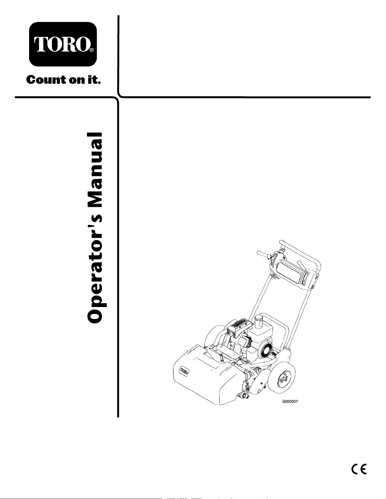
Greensmaster® Flex21
Walk-Behind Mower
Model No. 04021 (Traction Unit) —Serial No. 250000001
and Up
Model No. 04200 (Cutting Unit) —Serial No. 250000001 and
Up
Register your product at www.Toro.com Original Instructions (EN)
Page 2

Warning
CALIFORNIA
Pr oposition 65 W ar ning
T he engine exhaust fr om this pr oduct contains
chemicals kno wn to the State of Calif or nia to
cause cancer , bir th defects, or other r epr oducti v e
har m.
T his spark ignition system complies with Canadian
ICES-002
Contents
Introduction . . . . . . . . . . . . . . . . . . . . . . . . . . . . . . . . . . . . . . . . . . . . . . . . . . . . . . . . . 2
Safety . . . . . . . . . . . . . . . . . . . . . . . . . . . . . . . . . . . . . . . . . . . . . . . . . . . . . . . . . . . . . . . . . . 4
Safe Operating Practices . . . . . . . . . . . . . . . . . . . . . . . . . . . 4
T oro Mo w er Safety . . . . . . . . . . . . . . . . . . . . . . . . . . . . . . . . . . 5
Sound Pressure Lev el . . . . . . . . . . . . . . . . . . . . . . . . . . . . . . . 6
Sound P o w er Lev el . . . . . . . . . . . . . . . . . . . . . . . . . . . . . . . . . . 6
Vibration Lev el . . . . . . . . . . . . . . . . . . . . . . . . . . . . . . . . . . . . . . . 6
Safety and Instr uctional Decals . . . . . . . . . . . . . . . . . 7
Setup . . . . . . . . . . . . . . . . . . . . . . . . . . . . . . . . . . . . . . . . . . . . . . . . . . . . . . . . . . . . . . . . . . . 9
1 Installing the Handle . . . . . . . . . . . . . . . . . . . . . . . . . . . . . 9
2 Adjusting the Handle . . . . . . . . . . . . . . . . . . . . . . . . . . . 10
3 Installing the T ranspor t W heels . . . . . . . . . . . . . 10
4 Chec king Fluid Lev els . . . . . . . . . . . . . . . . . . . . . . . . . 11
5 Installing the Grass Bask et . . . . . . . . . . . . . . . . . . . 11
6 R eading the Man uals and Viewing the
Video . . . . . . . . . . . . . . . . . . . . . . . . . . . . . . . . . . . . 11
Product Ov er view . . . . . . . . . . . . . . . . . . . . . . . . . . . . . . . . . . . . . . . . . . . . . . . 13
Controls . . . . . . . . . . . . . . . . . . . . . . . . . . . . . . . . . . . . . . . . . . . . . . 13
Specifications . . . . . . . . . . . . . . . . . . . . . . . . . . . . . . . . . . . . . . . 14
Operation . . . . . . . . . . . . . . . . . . . . . . . . . . . . . . . . . . . . . . . . . . . . . . . . . . . . . . . . . . 15
T hink Safety First . . . . . . . . . . . . . . . . . . . . . . . . . . . . . . . . . . 15
Chec king the Engine Oil Lev el . . . . . . . . . . . . . . . . 15
Filling the Fuel T ank . . . . . . . . . . . . . . . . . . . . . . . . . . . . . . 15
Chec king the Interloc k Switc h
Operation . . . . . . . . . . . . . . . . . . . . . . . . . . . . . . 16
Star ting and Stopping the Engine . . . . . . . . . . . . . 16
T ranspor t Operation . . . . . . . . . . . . . . . . . . . . . . . . . . . . . 16
Pre paring to Mo w . . . . . . . . . . . . . . . . . . . . . . . . . . . . . . . . . 17
Mo wing Operation . . . . . . . . . . . . . . . . . . . . . . . . . . . . . . . . 17
Maintenance . . . . . . . . . . . . . . . . . . . . . . . . . . . . . . . . . . . . . . . . . . . . . . . . . . . . . . . 19
R ecommended Maintenance
Sc hedule(s) . . . . . . . . . . . . . . . . . . . . . . . . . . . . . . . . . . . 19
Daily Maintenance Chec klist . . . . . . . . . . . . . . . . . . . 20
Engine Maintenance . . . . . . . . . . . . . . . . . . . . . . . . . . . . . . . . . . . . 21
Engine Oil . . . . . . . . . . . . . . . . . . . . . . . . . . . . . . . . . . . . . . . . . . . 21
Ser vicing the Air Cleaner . . . . . . . . . . . . . . . . . . . . . . . . 21
R e placing the Spark Plug . . . . . . . . . . . . . . . . . . . . . . . . 22
Fuel System Maintenance . . . . . . . . . . . . . . . . . . . . . . . . . . . . . . 23
Cleaning the Fuel Filter . . . . . . . . . . . . . . . . . . . . . . . . . . 23
Electrical System Maintenance . . . . . . . . . . . . . . . . . . . . . . . 23
Ser vicing the Interloc k Switc h . . . . . . . . . . . . . . . . 23
Dri v e System Maintenance . . . . . . . . . . . . . . . . . . . . . . . . . . . . 23
Chec king the T ransmission Fluid
Lev el . . . . . . . . . . . . . . . . . . . . . . . . . . . . . . . . . . . . . 23
Changing the T ransmission Fluid . . . . . . . . . . . . . 24
Brak e Maintenance . . . . . . . . . . . . . . . . . . . . . . . . . . . . . . . . . . . . . . 24
Adjusting the Ser vice/P arking
Brak e . . . . . . . . . . . . . . . . . . . . . . . . . . . . . . . . . . . . 24
Belt Maintenance . . . . . . . . . . . . . . . . . . . . . . . . . . . . . . . . . . . . . . . . . 24
Adjusting the Belts . . . . . . . . . . . . . . . . . . . . . . . . . . . . . . . . 24
Controls System Maintenance . . . . . . . . . . . . . . . . . . . . . . . . 27
Adjusting the T raction Control . . . . . . . . . . . . . . . . 27
Adjusting the R eel Control . . . . . . . . . . . . . . . . . . . . . 28
Cutting Unit Maintenance . . . . . . . . . . . . . . . . . . . . . . . . . . . . . . 28
Se parating the Cutting Unit from the
T raction Unit . . . . . . . . . . . . . . . . . . . . . . . . . 28
Lev eling the R ear R oller to the
R eel . . . . . . . . . . . . . . . . . . . . . . . . . . . . . . . . . . . . . . 29
Adjusting the Bedknife to the R eel . . . . . . . . . . . 29
Adjusting the Height of Cut . . . . . . . . . . . . . . . . . . . . 30
Adjusting the Cut-Off Bar . . . . . . . . . . . . . . . . . . . . . . 31
Ser vicing the Bedbar . . . . . . . . . . . . . . . . . . . . . . . . . . . . . . 31
Bac klapping the R eel . . . . . . . . . . . . . . . . . . . . . . . . . . . . . 32
Storag e . . . . . . . . . . . . . . . . . . . . . . . . . . . . . . . . . . . . . . . . . . . . . . . . . . . . . . . . . . . . . . 33
Introduction
R ead this infor mation carefully to lear n ho w to operate
and maintain y our product properly and to a v oid injur y
and product damag e . Y ou are responsible for operating
the product properly and safely .
Y ou ma y contact T oro directly at www .T oro .com for
product and accessor y infor mation, help finding a
dealer , or to register y our product.
W henev er y ou need ser vice , g en uine T oro par ts , or
additional infor mation, contact an A uthorized Ser vice
Dealer or T oro Customer Ser vice and ha v e the model
and serial n umbers of y our product ready . Figure 1
and Figure 2 identify the location of the model and
serial n umbers on the product. W rite the n umbers in
the space pro vided.
© 2004—The Toro® Company
8111 Lyndale Avenue South
Bloomington, MN 55420
Contact us at www.Toro.com.
2
Printed in the USA.
All Rights Reserved
Page 3
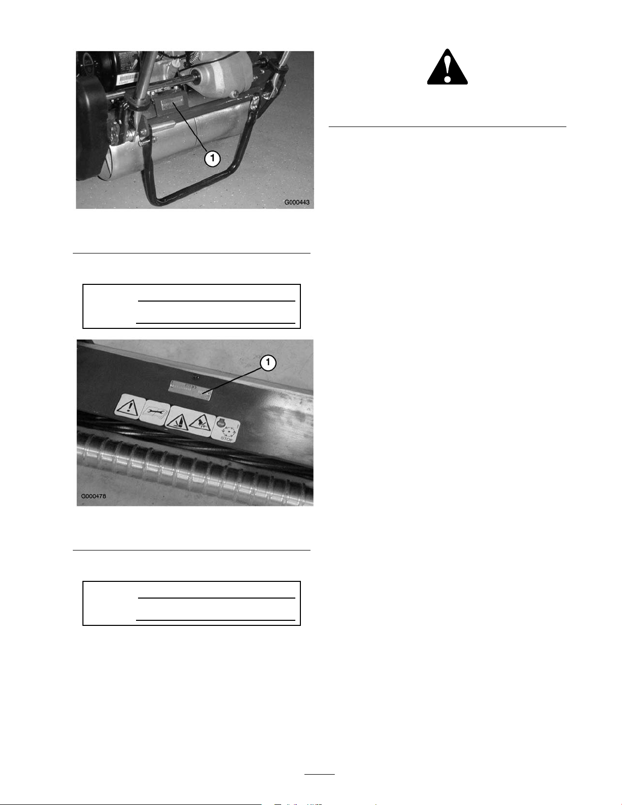
Figure 1
1. Location of the model and serial numbers-Traction unit
T raction unit:
Model No.
Serial No.
Figure 3
1. Safety alert symbol.
T his man ual uses tw o other w ords to highlight
infor mation. Impor tant calls attention to special
mec hanical infor mation and Note emphasizes g eneral
infor mation w or th y of special attention.
Figure 2
1. Location of the model and serial numbers-Cutting Unit
Cutting unit:
Model No.
Serial No.
T his man ual identifies potential hazards and has
safety messag es identified b y the safety aler t symbol
( Figure 3 ), whic h signals a hazard that ma y cause
serious injur y or death if y ou do not follo w the
recommended precautions .
3
Page 4

Safety
T his mac hine meets or ex ceeds CEN standard
EN 836:1997, ISO standard 5395:1990, and ANSI
B71.4-1999 specifications in effect at the time of
production when the Operator Presence Kit, P ar t No .
105-5333 is installed.
Improper use or maintenance b y the operator or o wner
can result in injur y . T o reduce the potential for injur y ,
comply with these safety instr uctions and alw a ys pa y
attention to the safety aler t symbol, whic h means
CA UTION , W ARNING , or D ANGER-“personal
safety instr uction." F ailure to comply with the
instr uction ma y result in personal injur y or death.
Safe Operating Practices
T he follo wing instr uctions are from the CEN standard
EN 836:1997, ISO standard 5395:1990, and ANSI
B71.4-1999.
Training
• R ead the Operator’ s Man ual and other training
material carefully . Be familiar with the controls ,
safety signs , and the proper use of the equipment.
• Nev er allo w c hildren or people unfamiliar with
these instr uctions to use or ser vice the mo w er .
Local regulations ma y restrict the ag e of the
operator .
• Nev er mo w while people , especially c hildren, or
pets are nearb y .
• K ee p in mind that the operator or user is
responsible for accidents or hazards occur ring to
other people or their proper ty .
• T he o wner/user can prev ent and is responsible for
accidents or injuries occur ring to himself or herself ,
other people , or proper ty .
Preparation
• W hile mo wing, alw a ys w ear substantial footw ear ,
long trousers , hard hat, safety glasses , and ear
protection. Long hair , loose clothing, or jew elr y
ma y g et tangled in mo ving par ts . Do not operate
the equipment when barefoot or w earing open
sandals .
• T horoughly inspect the area where the equipment
is to be used and remo v e all objects whic h ma y be
thro wn b y the mac hine .
• W ar ning-Fuel is highly flammable . T ak e the
follo wing precautions:
– Store fuel in containers specifically designed
for this pur pose .
– R efuel outdoors only and do not smok e while
refuelling .
– Add fuel before star ting the engine . Nev er
remo v e the cap of the fuel tank or add fuel
while the engine is r unning or when the engine
is hot.
– If fuel is spilled, do not attempt to star t the
engine but mo v e the mac hine a w a y from the
area of spillag e and a v oid creating any source
of ignition until fuel v apors ha v e dissipated.
– R e place all fuel tanks and container caps
securely .
• R e place faulty silencers .
• Ev aluate the ter rain to deter mine what accessories
and attac hments are needed to properly and
safely perfor m the job . Only use accessories and
attac hments appro v ed b y the man ufacturer .
• Chec k that operator’ s presence controls , safety
switc hes and shields are attac hed and functioning
properly . Do not operate unless they are
functioning properly .
Operation
• Do not operate the engine in a confined space
where dang erous carbon mono xide fumes can
collect.
• Mo w only in da ylight or in g ood ar tificial light.
• Before attempting to star t the engine , diseng ag e all
blade attac hment clutc hes , shift into neutral, and
eng ag e the parking brak e .
• Do not use on slopes of more than 15°.
• R emember there is no suc h thing as a safe slope .
T ra v el on g rass slopes requires par ticular care . T o
guard ag ainst o v er tur ning:
– do not stop or star t suddenly when g oing up
or do wnhill;
– eng ag e clutc h slo wly , alw a ys k ee p mac hine in
g ear , especially when tra v elling do wnhill;
– mac hine speeds should be k e pt lo w on slopes
and during tight tur ns;
– sta y aler t for humps and hollo ws and other
hidden hazards;
– nev er mo w across the face of the slope , unless
the mo w er is designed for this pur pose .
• Sta y aler t for holes in the ter rain and other hidden
hazards .
• W atc h out for traffic when crossing or near
roadw a ys .
• Stop the blades rotating before crossing surfaces
other than g rass .
4
Page 5

• W hen using any attac hments , nev er direct disc harg e
of material to w ard b ystanders nor allo w any one
near the mac hine while in operation.
• Nev er operate the mac hine with damag ed guards ,
shields , or without safety protecti v e devices in
place . Be sure all interloc ks are attac hed, adjusted
properly , and functioning properly .
• Do not c hang e the engine g o v er nor settings or
o v erspeed the engine . Operating the engine at
ex cessi v e speed ma y increase the hazard of personal
injur y .
• Before lea ving the operator’ s position:
– stop on lev el g round;
– diseng ag e the po w er tak e-off and lo w er the
attac hments;
– c hang e into neutral and set the parking brak e;
– stop the engine .
• Diseng ag e dri v e to attac hments when transpor ting
or not in use .
• Stop the engine and diseng ag e dri v e to attac hment
– before refuelling;
– before remo ving the g rass catc her/catc hers;
– before making height adjustment unless
adjustment can be made from the operator’ s
position.
– before clearing bloc kag es;
– before c hec king, cleaning or w orking on the
mo w er;
– after striking a foreign object or if an abnor mal
vibration occurs . Inspect the mo w er for
damag e and mak e re pairs before restar ting and
operating the equipment.
• R educe the throttle setting before stopping engine
and, if the engine is pro vided with a fuel shut-off
v alv e , tur n the v alv e off at the conclusion of
mo wing .
• K ee p hands and feet a w a y from the cutting unit.
• Slo w do wn and use caution when making tur ns
and crossing roads and sidew alks . Stop reels if not
mo wing .
• Do not operate the mo w er under the influence of
alcohol or dr ugs
• Use care when loading or unloading the mac hine
into a trailer or tr uc k
• Use care when approac hing blind cor ners , shr ubs ,
trees , or other objects that ma y obscure vision.
Maintenance and Storage
• K ee p all n uts , bolts and screws tight to be sure the
equipment is in safe w orking condition.
• Nev er store the equipment with fuel in the tank
inside a building where fumes ma y reac h an open
flame or spark.
• Allo w the engine to cool before storing in any
enclosure .
• T o reduce the fire hazard, k ee p the engine , silencer ,
batter y compar tment and fuel storag e area free of
g rass , lea v es , or ex cessi v e g rease .
• Chec k the g rass catc her frequently for w ear or
deterioration.
• K ee p all par ts in g ood w orking condition and all
hardw are and h y draulic fittings tightened. R e place
all w or n or damag ed par ts and decals .
• If the fuel tank has to be drained, do this outdoors .
• Be careful during adjustment of the mac hine to
prev ent entrapment of the fing ers betw een mo ving
blades and fix ed par ts of the mac hine .
• Diseng ag e dri v es , diseng ag e the cutting unit, set
parking brak e , stop engine and disconnect spark
plug wire . W ait for all mo v ement to stop before
adjusting, cleaning or re pairing .
• Clean g rass and debris from cutting unit, dri v es ,
m ufflers , and engine to help prev ent fires . Clean up
oil or fuel spillag e .
• Carefully release pressure from components with
stored energ y .
• Disconnect batter y and remo v e spark plug wire
before making any re pairs . Disconnect the neg ati v e
ter minal first and the positi v e last. R econnect
positi v e first and neg ati v e last.
• Use care when c hec king the reel. W ear glo v es and
use caution when ser vicing them.
• K ee p hands and feet a w a y from mo ving par ts . If
possible , do not mak e adjustments with the engine
r unning .
Toro Mower Safety
T he follo wing list contains safety infor mation specific
to T oro products or other safety infor mation that y ou
m ust kno w that is not included in the CEN , ISO , or
ANSI standard.
T his product is capable of amputating hands and
feet and thro wing objects . Alw a ys follo w all safety
instr uctions to a v oid serious injur y or death.
Use of this product for pur poses other than its intended
use could pro v e dang erous to user and b ystanders .
• Kno w ho w to stop the engine quic kly .
• Do not operate the mac hine while w earing tennis
shoes or sneak ers .
5
Page 6

• W earing safety shoes and long pants is advisable
and required b y some local ordinances and
insurance regulations .
• Handle g asoline carefully . Wipe up any spills .
• Chec k the safety interloc k switc hes daily for proper
operation. If a switc h should fail, re place the switc h
before operating the mac hine . After ev er y tw o
years , re place all interloc k switc hes in the safety
system, reg ardless if they are w orking properly or
not.
• Alw a ys stand behind the handle when star ting and
operating the mac hine .
• T o star t and stop the engine:
– Open fuel shut-off v alv e .
– V erify that the traction and reel dri v e control
lev ers on handle are in Neutral position.
– Mo v e on/off switc h to ON position, set c hok e
to full c hok e position (cold star t) and throttle
to half throttle .
– Pull star ter cord to star t engine .
– Mo v e throttle to Slo w and on/off switc h to
Off position to stop engine .
• T o transpor t mo w er from one area to another :
– Install transpor t wheels .
– Diseng ag e reel dri v e .
– Star t engine .
– Press do wn on handle to raise front of mo w er
and eng ag e traction dri v e .
• Before beginning mo wing operation:
– Diseng ag e traction dri v e .
– Stop engine .
– R emo v e transpor t wheels .
– Star t engine
– Eng ag e reel dri v e .
• Using the mac hine demands attention. T o prev ent
loss of control:
– Do not dri v e close to sand traps , ditc hes ,
creeks , or other hazards .
– R educe speed when making shar p tur ns . A v oid
sudden stops and star ts .
– W hen near or crossing roads , alw a ys yield the
right-of-w a y .
– Apply the ser vice brak es when g oing do wnhill
to k ee p forw ard speed slo w and to maintain
control of the mac hine .
• T he g rass bask et m ust be in place during operation
of the reels or thatc hers for maxim um safety . Shut
the engine off before emptying the bask ets .
• Do not touc h the engine , m uffler , or exhaust pipe
while the engine is r unning or soon after it has
stopped because these areas could be hot enough
to cause bur ns .
• Sta y clear of the rotating screen at the side of the
engine to prev ent direct contact with y our body
or clothing .
• W hen a person or pet appears unexpectedly in
or near the mo wing area, stop mo wing . Careless
operation, combined with ter rain angles , ricoc hets ,
or improperly positioned guards can lead to thro wn
object injuries . Do not resume mo wing until the
area is cleared.
Maintenance and Storage
• Chec k all fuel lines for tightness and w ear on a
regular basis . Tighten or re pair them as needed.
• If the engine m ust be r unning to perfor m a
maintenance adjustment, k ee p hands , feet, clothing,
and any par ts of the body a w a y from the cutting
unit, attac hments , and any mo ving par ts , especially
the screen at the side of the engine . K ee p ev er y one
a w a y .
• T o ensure safety and accuracy , ha v e an A uthorized
T oro Distributor c hec k the maxim um engine speed
with a tac hometer . Maxim um g o v er ned engine
speed should be 3600 RPM.
• If major re pairs are ev er needed or if assistance is
desired, contact an A uthorized T oro Distributor .
• Use only T oro-appro v ed attac hments and
re placement par ts . T he w ar ranty ma y be v oided if
used with unappro v ed attac hments .
Sound Pressure Level
T his unit has an equi v alent contin uous A-w eighted
sound pressure at the operator ear of: 84 dB(A), based
on measurements of identical mac hines per procedures
outlined in Directi v e 98/37/EC and amendments .
Sound Power Level
T his unit has a guaranteed sound po w er lev el of:
95 dB A/1 pW , based on measurements of identical
mac hines per Directi v e 2000/14/EC and amendments .
Vibration Level
T his unit has a hand-ar m vibration lev el of 4.50 m/s
based on measurements of identical mac hines per ISO
5349 procedures .
2
,
6
Page 7
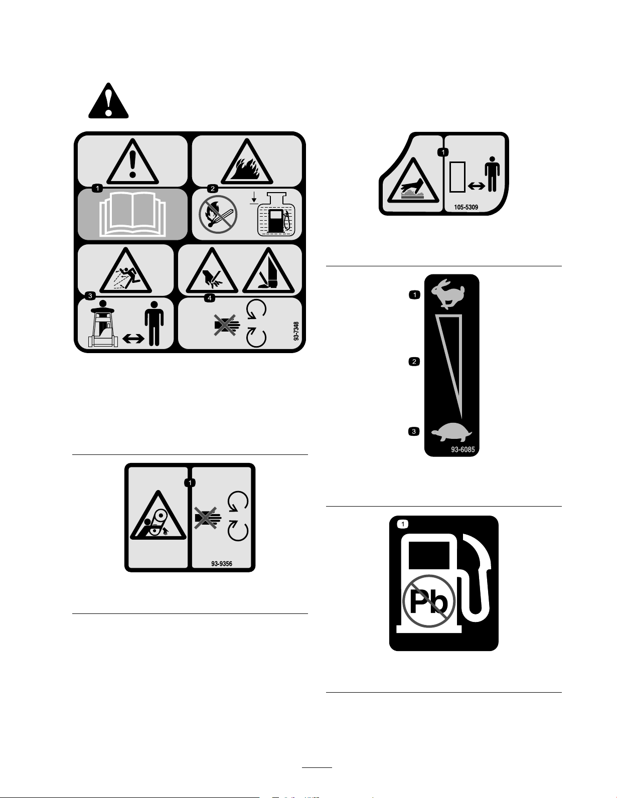
Safety and Instructional Decals
Safety decals and instr uctions are easily visible to the operator and are located near any area of
potential dang er . R e place any decal that is damag ed or lost.
105-5309
1. Hot surface/burn hazard—keep a safe distance from the hot
surface.
93-7348
1. Warning—read the Operator’s Manual .
2. Fire hazard—no re, open ames, or smoking; when adding
fuel to the tank, leave space between the fuel and the top of
the tank.
3. Thrown object hazard—keep bystanders a safe distance from
the machine.
4. Cutting hazard of hand or foot—stay away from moving
parts
93-9356
1. Entanglement hazard—stay away from moving parts.
1. Fast
2. Continuous variable setting
93-6085
3. Slow
7
93-9886
1. Use unleaded gasoline.
Page 8
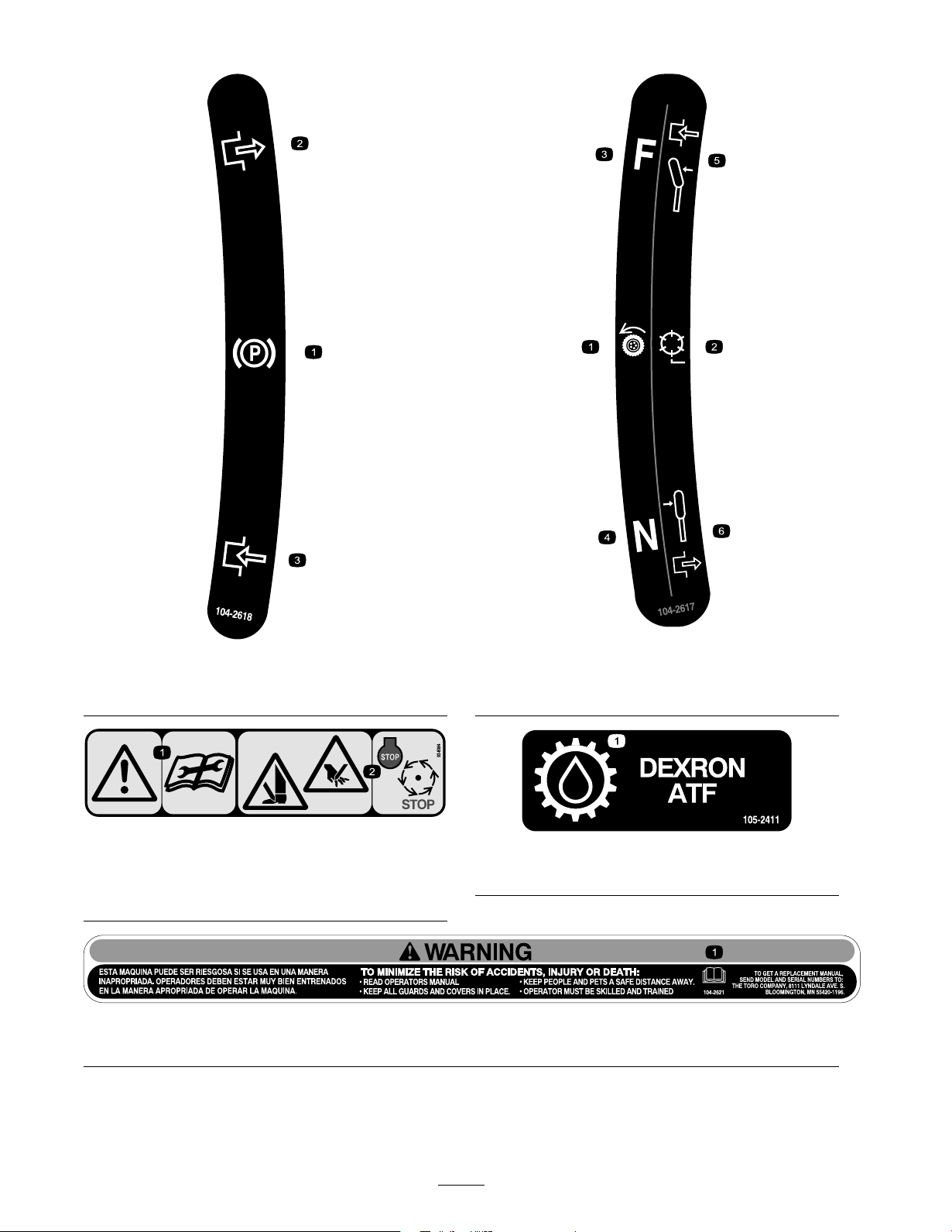
1. Parking brake
2. Disengage
104-2618
3. Engage
1. Traction drive 4. Forward
2. Reel drive 5. Lever engaged
3. Neutral 6. Lever disengaged
104-2617
93-8064
1. Warning—read the instructions before servicing or
performing maintenance.
2. Cutting hazard of hand or foot—stop the engine and wait
for moving parts to stop.
1. Read the Operator’s Manual .
105-2411
1. Transmission oil
104-2621
8
Page 9
Setup
Loose Parts
Use the chart below to verify that all parts have been shipped.
Step
1
2
3
4
5
6
Note: Deter mine the left and right sides of the
mac hine from the nor mal operating position.
Handle
No parts required
Transport wheels (Optional Transport
Wheel Kit, Model 04123)
No parts required
Grass basket
Operator’s Manual
Engine Operator’s Manual
Parts Catalog
Operator Video
Certicate of compliance
Description
Step
Qty.
1
Install the handle.
–
Adjust the handle.
2
Install the transport wheels.
Check the engine oil and transmission
–
uid levels
1
Install the grass basket.
1
1
Read the manuals and watch the video
1
before operating the machine.
1
1
Use
1
Installing the Handle
Parts needed for this step:
1
Handle
Procedure
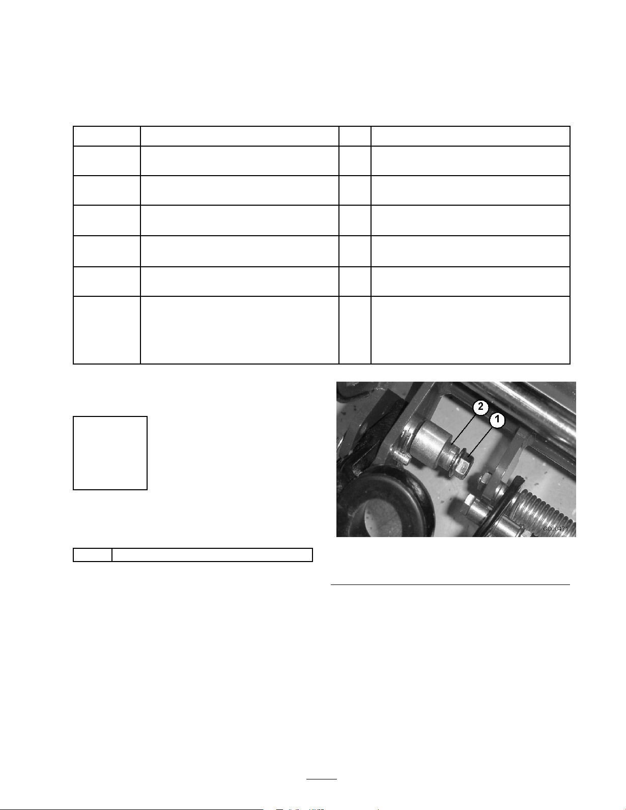
1. R emo v e the flang e loc k n ut from the capscrew and
pi v ot pin on eac h side of the mo w er ( Figure 4 ).
Figure 4
1. Flange lock nut
2. Inser t the handle ends through the slots in the
handle suppor t ar ms ( Figure 5 ).
2. Pivot pin
9
Page 10
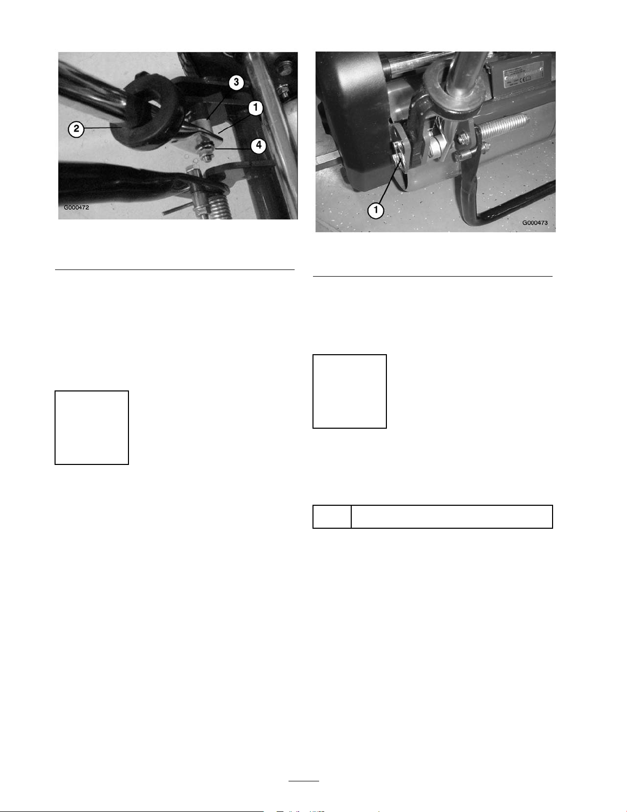
1. Left handle end
2. Support arm
Figure 5
3. Pivot pin
4. Locknut
Figure 6
1. Ring pins
3. Squeeze the handle ends inw ard and install them
on the ste p of the pi v ot pin ( Figure 5 ).
4. Secure the handle to the capscrew and pi v ot pin
with the flang e loc k n ut ( Figure 5 ).
5. Locate cable tie loosely securing throttle cable to
wire har ness . P osition cable tie appro ximately one
inc h behind transmission and tighten cable tie .
Step
2
Adjusting the Handle
No Parts Required
Procedure
1. R emo v e hair pin cotters from ring pins on eac h side
of mo w er ( Figure 6 ).
2. W hile suppor ting handle , remo v e ring pins from
eac h side and raise or lo w er handle to desired
operating position ( Figure 6 ).
3. R einstall ring pins and hair pin cotters .
Step
3
Installing the Transport
Wheels
Parts needed for this step:
Transport wheels (Optional Transport Wheel
2
Kit, Model 04123)
Procedure
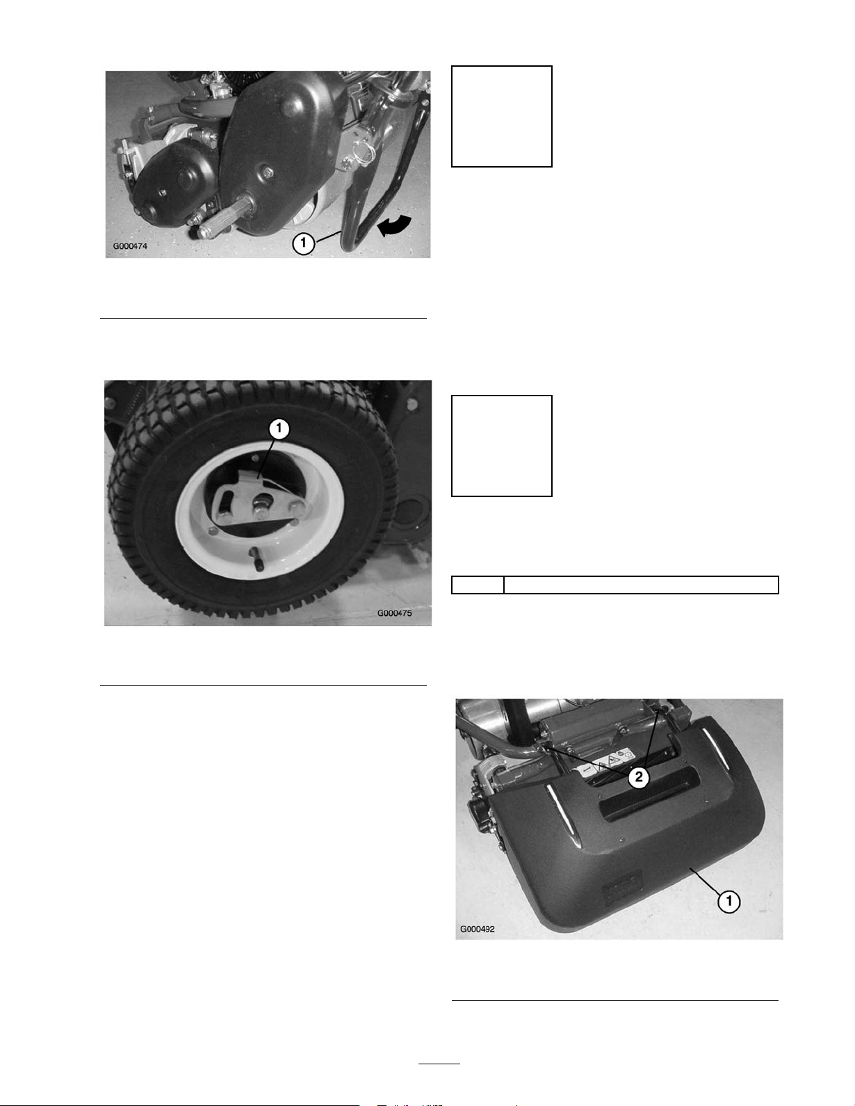
1. Push kic k stand do wn with foot and pull up on
handle suppor t until kic k stand has rotated forw ard,
o v er center ( Figure 7 ).
10
Page 11
Step
4
Checking Fluid Levels
No Parts Required
Figure 7
1. Kick stand
2. Press wheel loc king clip to w ard the center of wheel
and slide wheel onto hex shaft ( Figure 8 ).
Figure 8
1. Locking clip
Procedure
1. Chec k the engine oil lev el, refer to Chec king the
Engine Oil Lev el in Engine Maintenance , pag e 21 .
2. Chec k the transmission fluid lev el, refer to
Chec king the T ransmission Fluid Lev el in
Dri v e System Maintenance , pag e 23 .
Step
5
Installing the Grass Basket
Parts needed for this step:
1
Grass basket
Procedure
Grasp bask et b y top lip and slide bask et frame into the
recei v ers ( Figure 9 ).
3. R otate wheel bac k and for th until it slides
completely onto axle and loc king clip is secured
in g roo v e on axle shaft.
4. R e peat procedure on opposite side of mac hine .
5. Inflate the tires to 12-15 psi.
6. Carefully lift up on handle suppor t to release kic k
stand.
Figure 9
1. Grass basket 2. Basket receivers
11
Page 12

Step
6
Reading the Manuals and
Viewing the Video
Parts needed for this step:
1
Operator’s Manual
1
Engine Operator’s Manual
1
Parts Catalog
1
Operator Video
1
Certicate of compliance
Procedure
1. R ead the man uals .
2. View the Operator video .
3. Store the documentation in a safe place .
12
Page 13
Product Overview
v aried from 2400 RPM to 3600 RPM.
Traction and Reel Drive Engagement
Lever
throttle linkag e to carburetor . Engine speed can be
T he traction and reel dri v e eng ag ement lev er
( Figure 11 ) is located on front right side of control
panel. T raction lev er has tw o positions: Neutral and
F orw ard. Pushing lev er forw ard eng ag es traction dri v e .
T he reel dri v e lev er has tw o positions: Eng ag e and
Diseng ag e . Mo v e top of lev er to the left to eng ag e reel
or bac k to neutral to diseng ag e reel.
Service/Parking Brake
T he ser vice/parking brak e ( Figure 11 ) is located on
left front side of control panel. Pulling the lev er bac k
o v er center will set the parking brak e . Brak e m ust be
released before traction dri v e is eng ag ed.
Operator Presence Control
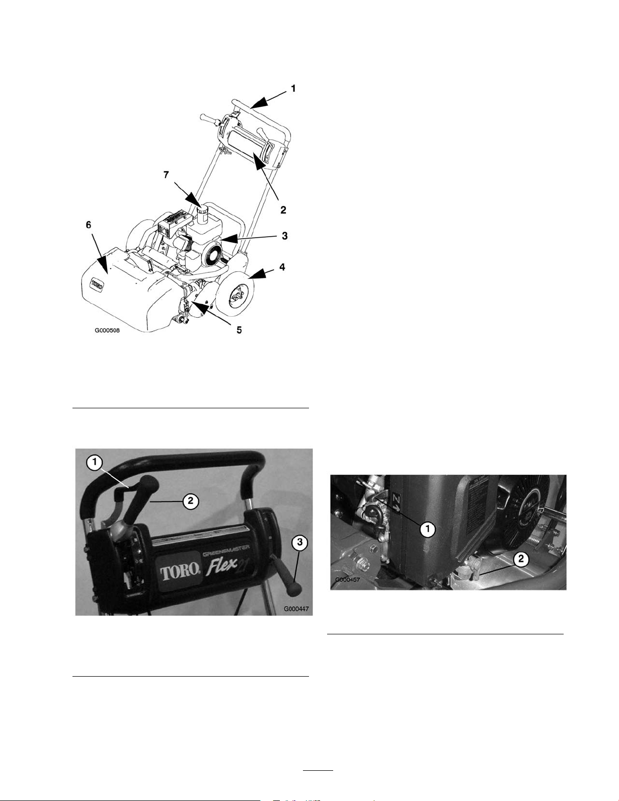
Figure 10
1. Handle
2. Control panel 6. Grass basket
3. Engine
4. Transport wheels
5. Cutting unit
7. Fuel tank
Controls
Figure 11
1. Throttle control 3. Service/parking brake
2. Traction & reel drive
engagement lever
T he optional operator presence control m ust be
eng ag ed before eng aging the traction lev er or the
engine will stop .
Choke Lever
T he c hok e lev er ( Figure 12 ) is located on left front
of engine . Lev er has tw o positions: R un and Chok e .
Mo v e lev er to Chok e position when star ting a cold
engine . After engine star ts mo v e lev er to R un position.
Figure 12
1. Choke lever 2. Fuel shut-off valve
Fuel Shut-Off Valve
Throttle Control
T he throttle control ( Figure 11 ) is located on rear right
side of control panel. Lev er connects to and operates
T he fuel shut-off v alv e ( Figure 12 ) is located on left
front of engine . V alv e has tw o positions: Closed and
Open. Mo v e lev er to closed position when storing
or transpor ting mac hine . Open v alv e before star ting
engine .
13
Page 14
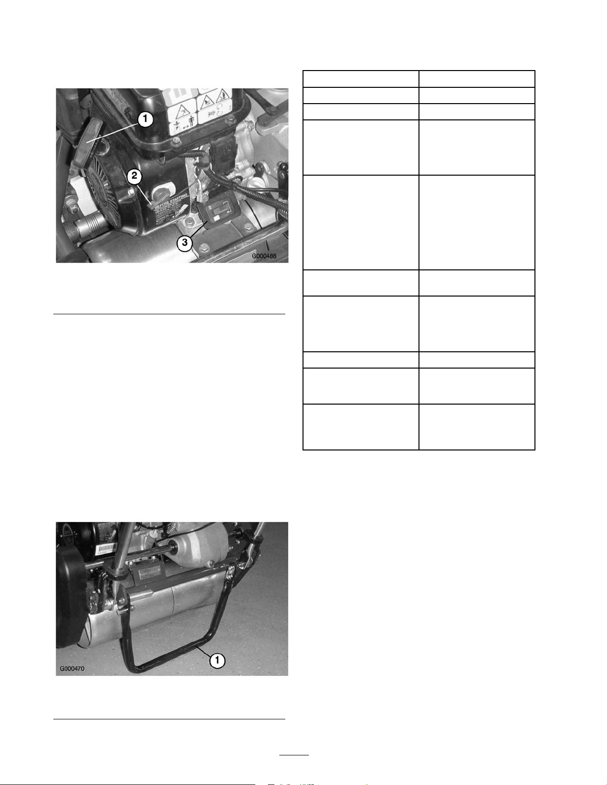
Recoil Starter
Specications
Pull recoil star ter handle ( Figure 13 ) to star t engine .
Figure 13
1. Recoil starter
2. On/off switch
3. Hour meter
On/Off Switch
T he on/off switc h ( Figure 13 ) is located on rear of
engine . Mo v e switc h to On position to star t engine and
Off to stop engine .
Hour Meter
T he hour meter ( Figure 13 ) located on rear of engine ,
indicates the total hours of mac hine operation.
Width 35-1/4"
Height
Length
Dry weight
Engine
Fuel capacity
Ground speed Mowing speed: 1.3 to
Width of cut
Height of cut
Clip frequency
40"
54"
238 lb. (108 kg) with
aluminum Wiehle roller,
kickstand and grass basket;
without transport tires and
groomer
Kawasaki, 4-cycle, 3.7 (2.7
kw) air cooled OHV engine,
3600 RPM, 7.57 cu in. (124
cc) displacement, cast iron
cylinder sleeve; electronic
ignition with integral
lighting coil; maximum
noise suppression mufer;
84 dB(A) at operator’s ear
2.64 qt. (2.5 l); regular
grade unleaded gasoline
3.5 MPH (2.1 to 5.6
km/h)Transport speed:
5.3 MPH (8.5 km/h)
maximum
21 in. (53.3 cm)
1/16 to 19/64 in. (1.5 to
7.5 mm) with Micro-Cut
bedknife
11 blade (standard): .16
in. (4.1 mm)11 blade
w/clip kit: .14 or .21 in.
(3.5 or 6.4 mm)
Kickstand
T he kic kstand ( Figure 14 ) is mounted to rear of
mac hine and is used to raise rear of mac hine for
installation or remo v al of transpor t wheels .
Figure 14
1. Kick stand
Attachments/Accessories
A selection of T oro appro v ed attac hments and
accessories are a v ailable for use with the mac hine to
enhance and expand its capabilities . Contact y our
A uthorized Ser vice Dealer or Distributor or g o to
www .T oro .com for a list of all appro v ed attac hments
and accessories .
14
Page 15
Operation
Note: Deter mine the left and right sides of the
mac hine from the nor mal operating position.
Think Safety First
Please carefully read all of the safety instr uctions and
decals in the safety section. Kno wing this infor mation
could help y ou or b ystanders a v oid injur y .
Checking the Engine Oil
Level
Chec k the engine oil lev el before eac h use or ev er y
8 operating hours , refer to Chec king the Engine Oil
Lev el in Engine Maintenance , pag e 21 .
Filling the Fuel Tank
Important: Nev er use methanol, gasoline
containing methanol, gasohol containing mor e
than 10% ethanol, gasoline additi v es, pr emium
gasoline, or white gas because the fuel system
could be dama ged. Do not mix oil with gasoline.
Gasoline is har mful or f atal if s w allo w ed.
Long-ter m exposur e to v apor s can cause serious
injur y and illness.
• A v oid pr olonged br eathing of v apor s.
• K eep f ace a w ay fr om nozzle and gas tank or
conditioner opening .
• K eep gas a w ay fr om ey es and skin.
In cer tain conditions, gasoline is extr emel y
flamma ble and highl y explosi v e. A fir e or
explosion fr om gasoline can bur n y ou and other s
and can dama ge pr oper ty .
• Fill the fuel tank outdoor s, in an open
ar ea, when the engine is cold. W ipe up an y
gasoline that spills.
• Do not fill the fuel tank completel y full. Add
gasoline to the fuel tank until the lev el is 1/4
to 1/2 in. (6 to 13 mm) belo w the bottom of
the filler neck. T his empty space in the tank
allo ws gasoline to expand.
• Nev er smok e when handling gasoline, and
stay a w ay fr om an open flame or wher e
gasoline fumes may be ignited by a spar k.
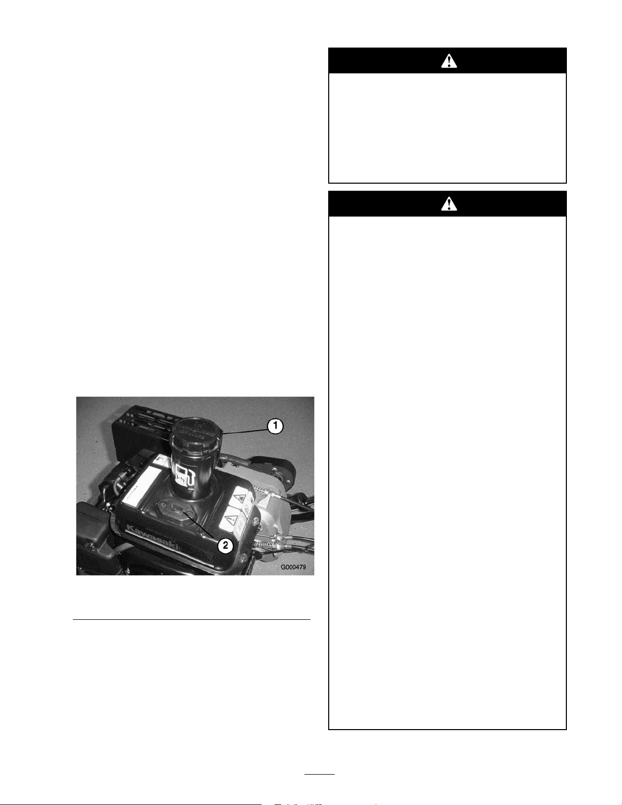
Figure 15
1. Fuel tank cap 2. Fuel gauge
• Stor e gasoline in an appr o v ed container and
k eep it out of the r each of childr en. Nev er
buy mor e than a 30-day suppl y of gasoline.
• Al w ays place gasoline container s on the
g r ound a w ay fr om y our v ehicle bef or e filling .
• Do not fill gasoline container s inside a
v ehicle or on a tr uck or trailer bed because
interior car pets or plastic tr uck bed liner s
may insulate the container and slo w the loss
of an y static charge.
• W hen practical, r emo v e gas-po w er ed
equipment fr om the tr uck or trailer and
r efuel the equipment with its wheels on the
g r ound.
• If this is not possible, then r efuel such
equipment on a tr uck or trailer fr om a
por ta ble container , rather than fr om a
gasoline dispenser nozzle.
• If a gasoline dispenser nozzle must be used,
k eep the nozzle in contact with the rim of the
fuel tank or container opening at all times
until fueling is complete.
15
Page 16
1. Clean around fuel tank cap and remo v e cap from
tank ( Figure 15 ). Using unleaded g asoline , fill fuel
tank no higher than to bottom of filter screen. Do
not o v erfill.
2. Install fuel tank cap and wipe up any spilled
g asoline .
Starting and Stopping the
Engine
Note: F or illustrations and descriptions of the
controls referenced in this section, refer to Controls ,
pag e 13 .
Checking the Interlock
Switch Operation
If safety inter lock s witches ar e disconnected
or dama ged the machine could operate
unexpectedl y causing per sonal injur y .
• Do not tamper with the inter lock s witches.
• Check the operation of the inter lock s witches
dail y and r eplace an y dama ged s witches
bef or e operating the machine.
• R eplace s witches ev er y tw o y ear s r egardless
of whether they ar e operating pr oper l y or not.
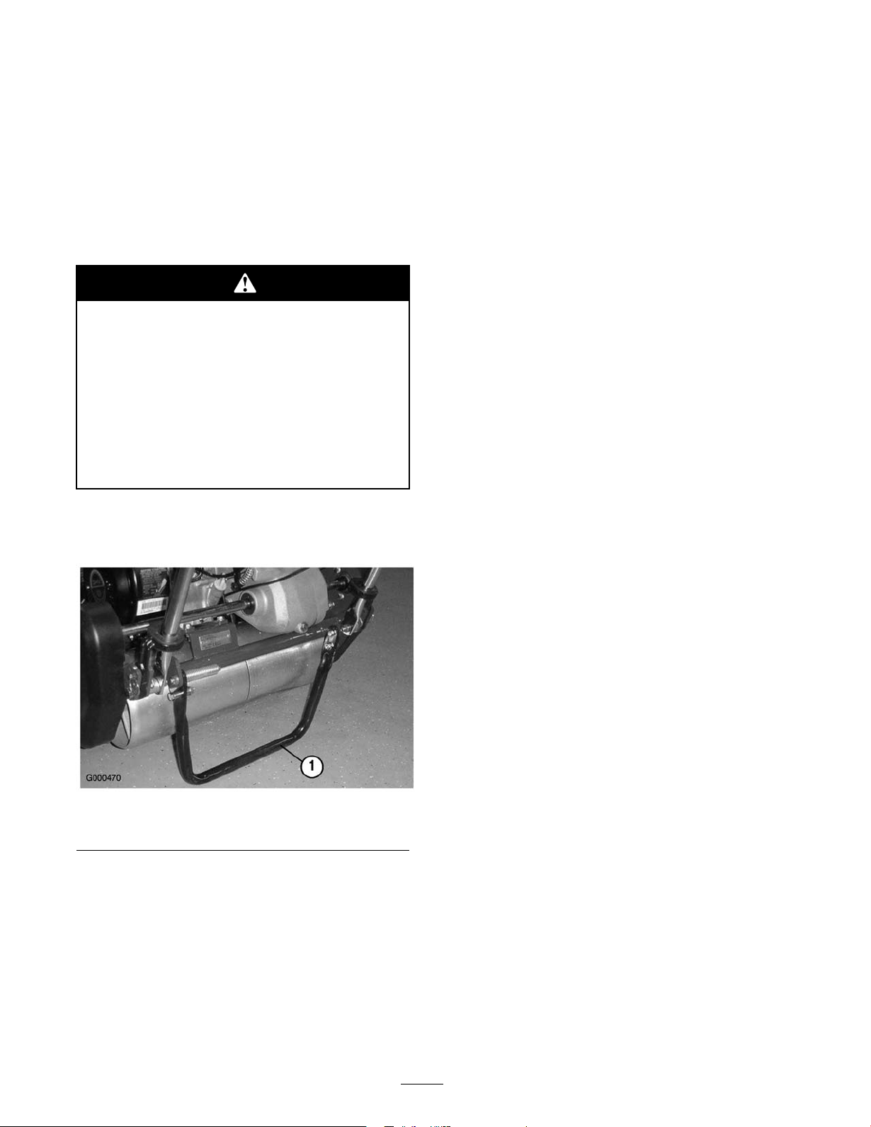
1. Push kic k stand do wn with foot and pull up on
handle suppor t until kic k stand has rotated forw ard,
o v er center ( Figure 16 ).
Starting the Engine
Note: Mak e sure spark plug wire is installed on spark
plug .
1. Mak e sure traction and reel dri v e lev ers are in
Diseng ag ed position.
Note: Engine will not star t if traction lev er is in
the eng ag ed position.
2. Open the fuel shut-off v alv e on the engine .
3. Mo v e the on/off switc h to the On position.
4. Mo v e the throttle control to the F ast position.
5. Mo v e the c hok e lev er to the half-open position
when star ting a cold engine . T he c hok e ma y not be
required when star ting a w ar m engine .
6. Pull the recoil star ter handle out until positi v e
eng ag ement results , then pull it vig orously to star t
the engine . Open the c hok e as engine w ar ms up .
Important: Do not pull r ecoil r ope to its
limit or let go of star ter handle when r ope is
pulled out because r ope may br eak or r ecoil
assembl y may be dama ged.
Figure 16
1. Kick stand
2. Place traction lev er into Eng ag e position and
engine controls in star ting position.
3. Attempt to star t engine . Engine should not star t.
If engine star ts , the interloc k switc h needs ser vice .
Cor rect problem before operating . R efer to
Ser vicing Interloc k Switc h, pag e .
4. Carefully lift up on handle to release kic k stand.
Stopping the Engine
1. Mo v e the traction and reel dri v e controls to the
Diseng ag ed position, the throttle control to Slo w ,
and the on/off switc h to Off .
2. Pull the spark plug wire off of the spark plug to
prev ent the possibility of accidental star ting before
storing mac hine .
3. Close the fuel shut-off v alv e before storing or
transpor ting mo w er in a v ehicle .
Transport Operation
1. Push kic k stand do wn with foot and pull up on
handle suppor t until kic k stand has rotated forw ard,
o v er center .
2. T o release kic kstand, pull up on handle and lo w er
rear of mo w er onto transpor t wheels .
3. Ensure traction and reel dri v e controls are in
Diseng ag e position and star t engine .
16
Page 17
4. Set throttle control to Slo w , tip front of mac hine up
g radually eng ag e traction dri v e and slo wly increase
engine speed.
5. Adjust throttle to operate mo w er at desired g round
speed and transpor t mo w er to desired destination.
Preparing to Mow
1. R etur n traction control lev er to Diseng ag e , throttle
to Slo w and stop engine .
2. Push kic k stand do wn with foot and pull up on
handle suppor t until kic k stand has rotated forw ard,
o v er center .
3. R emo v e transpor t wheels .
4. R elease kic kstand.
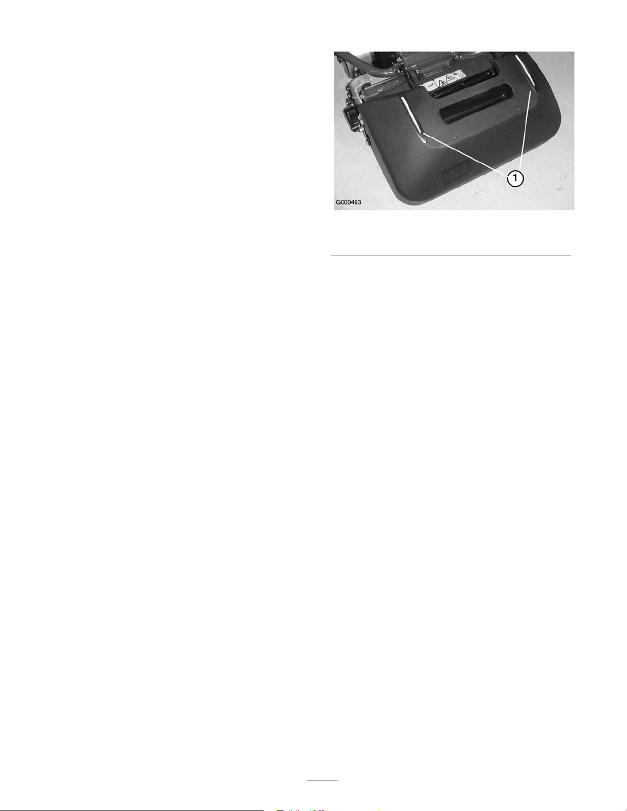
Figure 17
1. Alignment stripes
Mowing Operation
Proper use of the mac hine pro vides the smoothest turf
cutting a v ailable .
Important: Grass clippings act as a lubricant
when mo wing . Ex cessi v e operation of the cutting
unit with the a bsence of g rass clippings can
dama ge the cutting unit.
Prior to Mowing
Be sure the mo w er is carefully adjusted and is set ev enly
on both sides of the reel. Improper mo w er adjustment
is magnified in the appearance of the clipped turf .
R emo v e all foreign objects from turf prior to mo wing .
Mak e sure ev er y one , especially c hildren and pets , are
clear of the w ork area.
Method of Mowing
T he g reens should be mo w ed in a straight bac k and
for th direction across the g reen. A v oid circular mo wing
or tur ning the mo w er on g reens areas since scuffing
ma y occur . T ur ning the mo w er should be done off the
g reen b y raising the cutting reel (pushing the handle
do wn) and tur ning on the traction dr um. Mo wing
should be done at a nor mal w alking pace . F ast speeds
sa v es v er y little time and will result in an inferior
mo wing job .
Control Operation
T o operate the controls while mo wing:
1. Star t the engine , set the throttle at reduced speed,
push do wn on handle to raise cutting unit, mo v e
traction lev er to Eng ag ed position and transpor t
mo w er onto collar of g reen ( Figure 18 ).
2. Mo v e traction lev er to Diseng ag ed position and
Eng ag e reel dri v e lev er ( Figure 18 ).
T o assist in maintaining a straight line across the g reen
and to k ee p the mac hine an equal distance from the
edg e of the previous cut, use the alignment stripes on
the bask et ( Figure 17 ).
17
Page 18
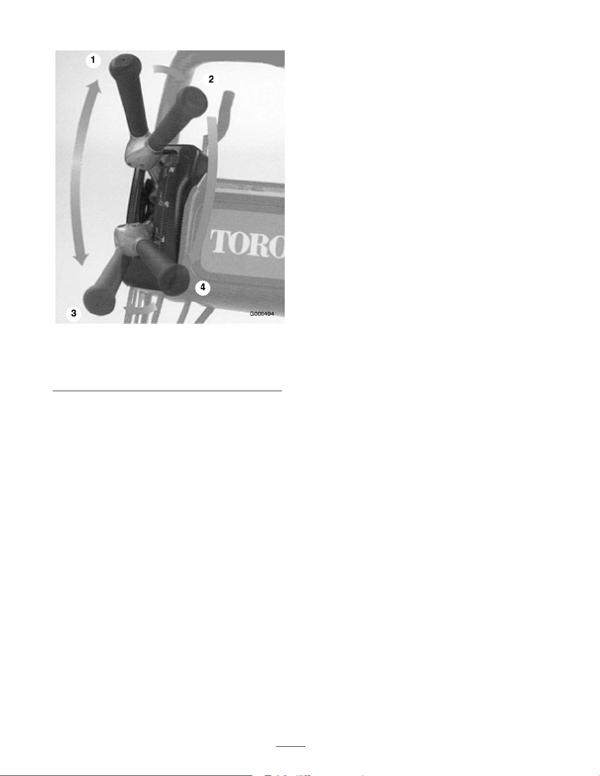
Figure 18
1. Traction drive -neutral 3. Traction drive-engaged
2. Traction drive neutral &
reel drive off
(transport)
4. Traction drive & reel drive
engaged
3. Mo v e traction lev er to Eng ag ed position, increase
throttle speed until the mo w er is tra v eling at the
desired g round speed, dri v e the mo w er out onto
the g reen area, lo w er the front of the mo w er do wn
and commence operation ( Figure 18 ).
After Mowing
1. Dri v e off g reen, mo v e reel dri v e and traction
control lev ers to Diseng ag e and stop the engine .
2. Empty the g rass catc her of clippings , install g rass
catc her and commence transpor t operation.
18
Page 19

Maintenance
Note: Deter mine the left and right sides of the mac hine from the nor mal operating position.
Recommended Maintenance Schedule(s)
Maintenance
Service Interval
After rst use
After the rst 25
operating hours
Before each use or
daily
Every 25 hours
Every 50 hours
Every 100 hours
Before storage
Every 2 years
Important: R efer to y our engine operator’ s man ual f or additional maintenance pr ocedur es.
Maintenance Procedure
• Change the engine oil.
• Clean the fuel lter.
• Change the transmission uid.
• Check the engine oil level.
• Clean the air cleaner (more often in dirty or dusty conditions).
• Change the engine oil.
• Clean the fuel lter.
• Check the transmission uid level.
• Clean or replace the paper air lter element (more often in dirty or
dusty conditions).
• Check the spark plug.
• Paint chipped surfaces.
• Replace the interlock switch.
• Change the transmission uid.
19
Page 20
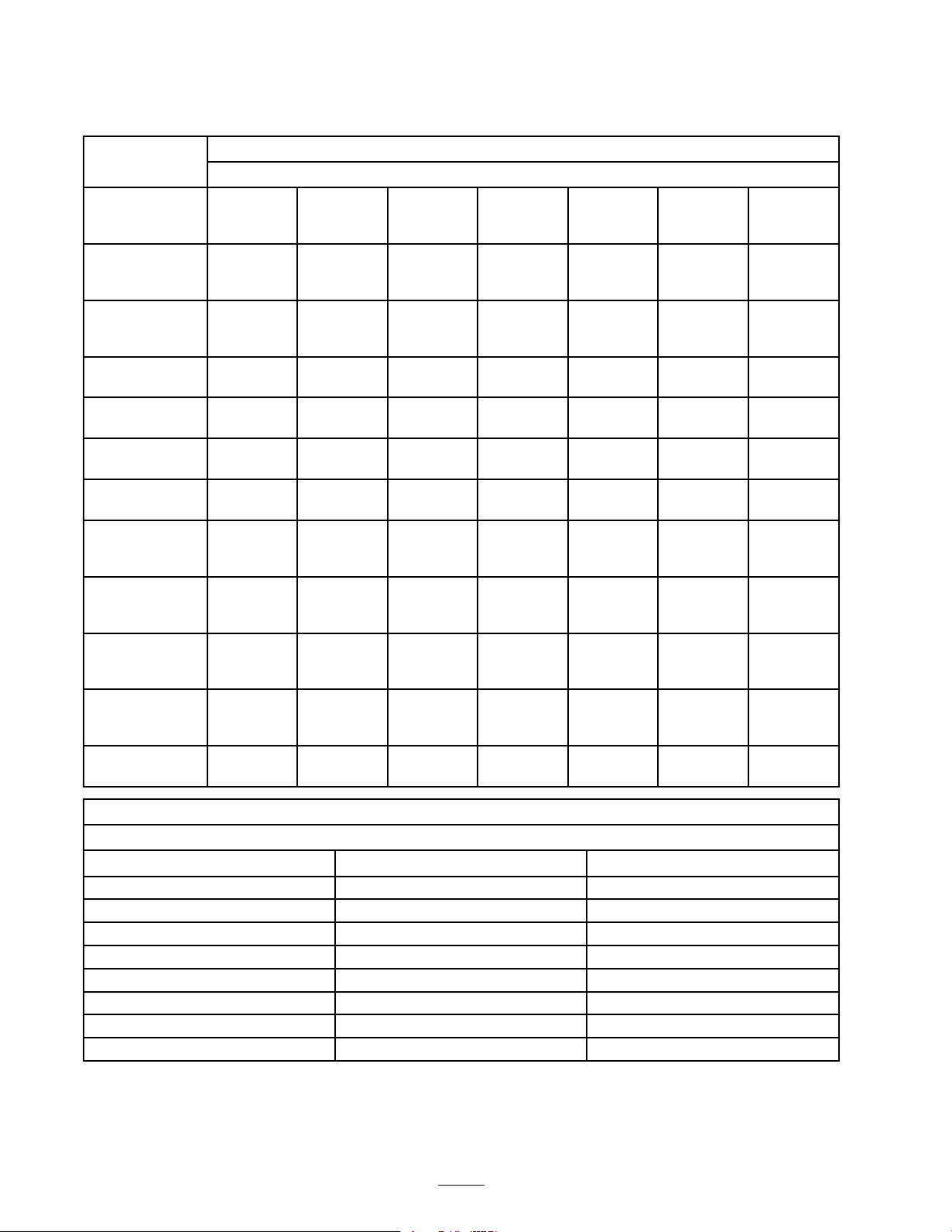
Daily Maintenance Checklist
Important: Duplicate this pa ge f or r outine use.
Maintenance
Check Item
Check the
safety interlock
operation.
Check the
parking brake
operation.
Check that pivot
joints operate
freely.
Check the fuel
level.
Check the engine
oil level.
Check the air
lter.
Clean the engine
cooling ns.
Check for
unusual engine
noises.
Check for
unusual
operating noises.
Check the
reel-to-bedknife
adjustment.
Check the
height-of-cut
adjustment.
Touch up
damaged paint.
For the week of:
Mon. Tues.
Wed. Thurs.
Fri.
Sat. Sun.
Notation for Areas of Concern
Inspection performed by:
Item Date
Information
20
Page 21
Engine Maintenance
Engine Oil
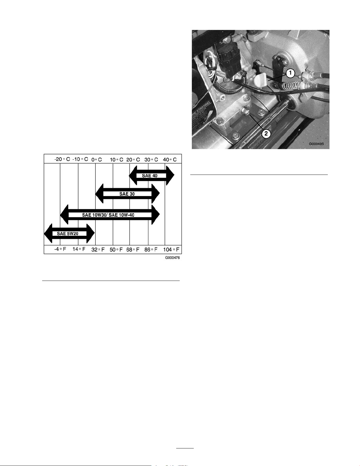
Chec k the engine oil lev el eac h time the mo w er is
used or after ev er y 8 operating hours . Chang e the
oil after the first 8 operating hours and ev er y 50
hours thereafter . More frequent oil c hang es are
required in dusty or dir ty conditions . T he crankcase
m ust be filled with appro ximately 20 fluid ounces of
proper viscosity oil before staring . T he engine uses
any high-quality oil ha ving the American P etroleum
Institute - APl - “ser vice classification" SF , SG , SH or
SJ . Oil viscosity - w eight - m ust be selected according
to ambient temperature . Figure 19 illustrates the
temperature/viscosity recommendations .
Figure 20
1. Oil level gauge 2. Drain plug
2. R emo v e oil lev el g aug e b y rotating it
countercloc kwise .
3. Wipe oil lev el g aug e clean and inser t it into filler
por t. Do not screw into por t. T hen remo v e
and c hec k lev el of oil. If lev el is lo w , add only
enough oil to raise lev el to bottom of filler opening .
R ec hec k lev el of oil. Do not o v erfill.
Figure 19
Note: Using m ulti-g rade oils (5W -20, 10W -30, and
10W -40) will increase oil consumption. Chec k the oil
lev el more frequently when using them.
Checking the Engine Oil Level
1. P osition mo w er so the engine is lev el and clean
around oil lev el g aug e ( Figure 20 ).
4. R einstall oil lev el g aug e and wipe up any spilled oil.
Changing the Engine Oil
1. Star t and r un engine for a few min utes to w ar m
the engine oil.
2. Place a drain pan at rear of mac hine under drain
plug ( Figure 20 ). R emo v e drain plug .
3. Push do wn on handle to tip mo w er and engine
bac kw ard, allo wing more oil to r un into drain pan.
4. Install drain plug and refill crankcase with proper
oil; refer to Chec king the Oil Lev el.
Servicing the Air Cleaner
Nor mally , clean air cleaner foam element after ev er y 25
operating hours . More frequent cleaning is required
when mo w er is operated in dusty or dir ty conditions .
1. Mak e sure wire is off spark plug .
2. R emo v e wing n uts securing air cleaner co v er to air
cleaner and remo v e co v er . Clean co v er thoroughly
( Figure 21 ).
21
Page 22
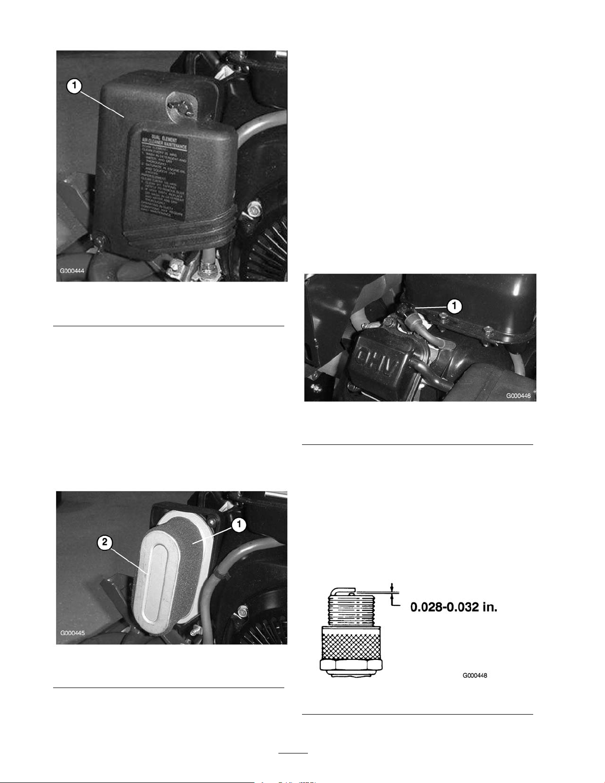
1. Air cleaner cover
4. W hen ser vicing foam element, c hec k condition of
paper element. Clean or re place ev er y 100 hours
or as required.
5. Install foam element, paper element, and air cleaner
co v er .
Important: Do not operate the engine
without the air cleaner element because
extr eme engine w ear and dama ge will lik el y
r esult.
Replacing the Spark Plug
Use an NGK BPR 5ES spark plug or equi v alent.
Cor rect air g ap is 0.028-0.032 in. R emo v e plug after
ev er y 100 operating hours and c hec k its condition.
1. Pull wire off spark plug ( Figure 23 ).
Figure 21
3. If foam element is dir ty , remo v e it from paper
element ( Figure 22 ). Clean thoroughly .
A. W ash foam element in a solution of liquid soap
and w ar m w ater . Squeeze to remo v e dir t, but
do not twist because foam ma y tear .
B . Dr y b y wrapping in a clean rag . Squeeze rag
and foam element to dr y .
C . Saturate element with clean engine oil. Squeeze
element to remo v e ex cess oil and to distribute
oil thoroughly . An oil damp element is
desirable .
Figure 23
1. Spark plug wire
2. Clean around spark plug and remo v e plug from
cylinder head.
Important: R eplace a crack ed, f ouled, or
dir ty spar k plug . Do not sand blast, scrape,
or clean electr odes because engine dama ged
could r esult fr om g rit entering the cylinder .
3. Set air g ap at 0.028-0.032 in. ( Figure 24 ). Install
cor rectly g apped spark plug and tighten fir mly to
17 ft.-lb .
Figure 22
1. Foam element 2. Paper element
Figure 24
22
Page 23
Fuel System
Maintenance
Cleaning the Fuel Filter
Initially , clean fuel filter after the first 25 hours of
operation; thereafter clean after ev er y 50 hours
operation.
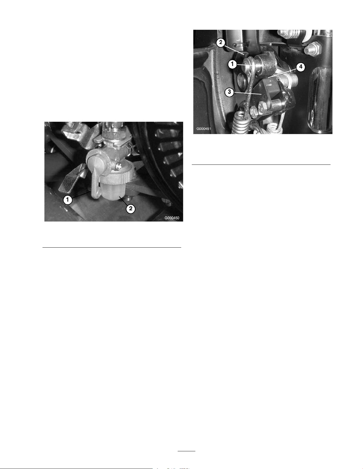
1. Close fuel shut off v alv e and unscrew bo wl from
filter body ( Figure 25 ).
Figure 25
1. Shut-off valve 2. Bowl
2. Clean bo wl and filter in clean g asoline and install.
Figure 26
1. Traction lever 3. Interlock switch
2. Neutral stop
3. Loosen interloc k switc h mounting fasteners
( Figure 26 ).
4. Place a .032" thic k shim betw een the traction lev er
and the interloc k switc h ( Figure 26 ).
5. Tighten interloc k switc h mounting fasteners .
R ec hec k g ap . T he traction lev er m ust not contact
the switc h.
6. Eng ag e traction lev er and v erify that the switc h
loses contin uity . R e place if required.
Important: R eplace inter lock s witch ev er y
2 y ear s.
4. .032" Gap
Electrical System
Maintenance
Servicing the Interlock
Switch
Use the follo wing procedure should the switc h need
adjustment or re placement.
1. Mak e sure the engine is off and traction lev er is
Diseng ag ed.
2. Eng ag e traction lev er until it contacts neutral stop
( Figure 26 ).
Drive System
Maintenance
Checking the Transmission
Fluid Level
T he transmission is filled at the factor y with
appro ximately 94 fluid ounces of Mobil Dexron lll
automatic transmission fluid. Chec k fluid lev el before
the engine is first star ted and ev er y 50 hours thereafter .
Note: T he seals used in the transmission are inter nally
lubricated with g rease . During initial operation of
mo w er , slight w ee ping of g rease from these seals will
occur . Wipe off ex cess g rease .
Important: Use onl y Mobil Dexr on lll or
equi v alent transmission fluids. Other fluids could
cause system dama ge.
1. Place the mo w er on its dr ums on a lev el surface .
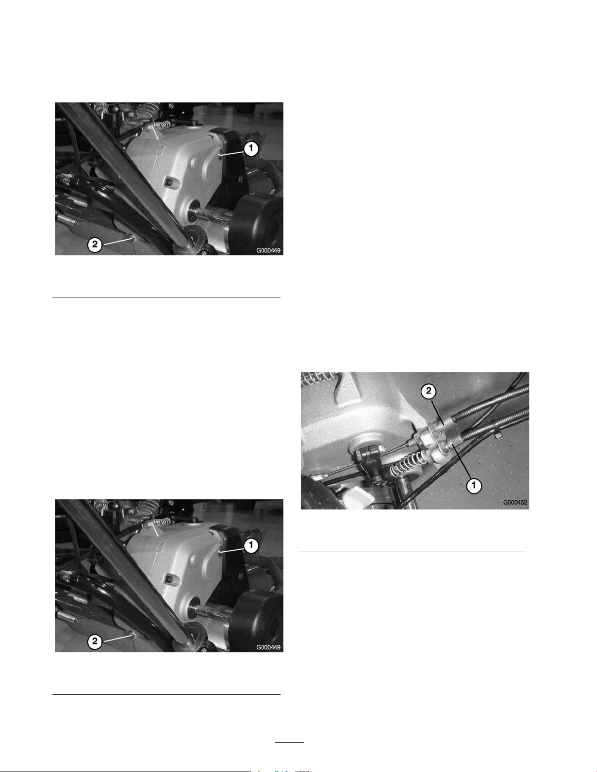
2. R emo v e the c hec k/fill plug from the right-hand
side of the transmission ( Figure 27 ).
23
Page 24
T he oil lev el should come to the bottom of the fill
hole . If it does not, add enough of the proper oil
type until the lev el reac hes the bottom of the fill
hole .
Figure 27
1. Check/ll plug 2. Drain plug
3. Install the plug .
Changing the Transmission
Fluid
3. Push do wn on the handle and tip the mac hine bac k.
R emo v e the c hec k/fill plug from the right-hand
side of the transmission ( Figure 28 ).
4. W hen the fluid is drained, install the drain plug .
5. Place the mo w er on its dr ums on a lev el surface .
6. Fill the transmission with appro ximately 94 fluid
ounces of the proper type of transmission fluid
until the lev el reac hes the bottom of the c hec k/fill
hole; refer to Chec king the T ransmission Fluid.
7. Install the c hec k/fill plug .
Brake Maintenance
Adjusting the
Service/Parking Brake
If ser vice/park brak e slips when operated, an
adjustment is required.
1. Mo v e ser vice/parking brak e lev er to Off position.
2. T o increase cable tension, loosen front cable jam
n ut and tighten bac k cable jam n ut ( Figure 29 )
until a force of 6-9 lb . is required to eng ag e brak e .
F orce to be measured at lev er knob . Do not o v er
adjust, or brak e band ma y drag .
Chang e the transmission fluid after the first 25 hours
of operation and ev er y 2 years thereafter .
Important: Use onl y Mobil Dexr on lll or
equi v alent transmission fluids. Other fluids could
cause system dama ge.
1. Place a drain pan at the rear of the mac hine .
2. R emo v e the drain plug from the rear of the
transmission ( Figure 28 ).
Figure 28
1. Check/ll plug 2. Drain plug
Figure 29
1. Traction cable 2. Service/parking brake cable
Belt Maintenance
Adjusting the Belts
Mak e sure belts are properly tensioned to assure proper
operation of the mac hine and unnecessar y w ear . Chec k
belts frequently .
Reel Drive Belt (Reel)
1. R emo v e the belt co v er mounting fasteners and belt
co v er to expose belt ( Figure 30 ).
24
Page 25
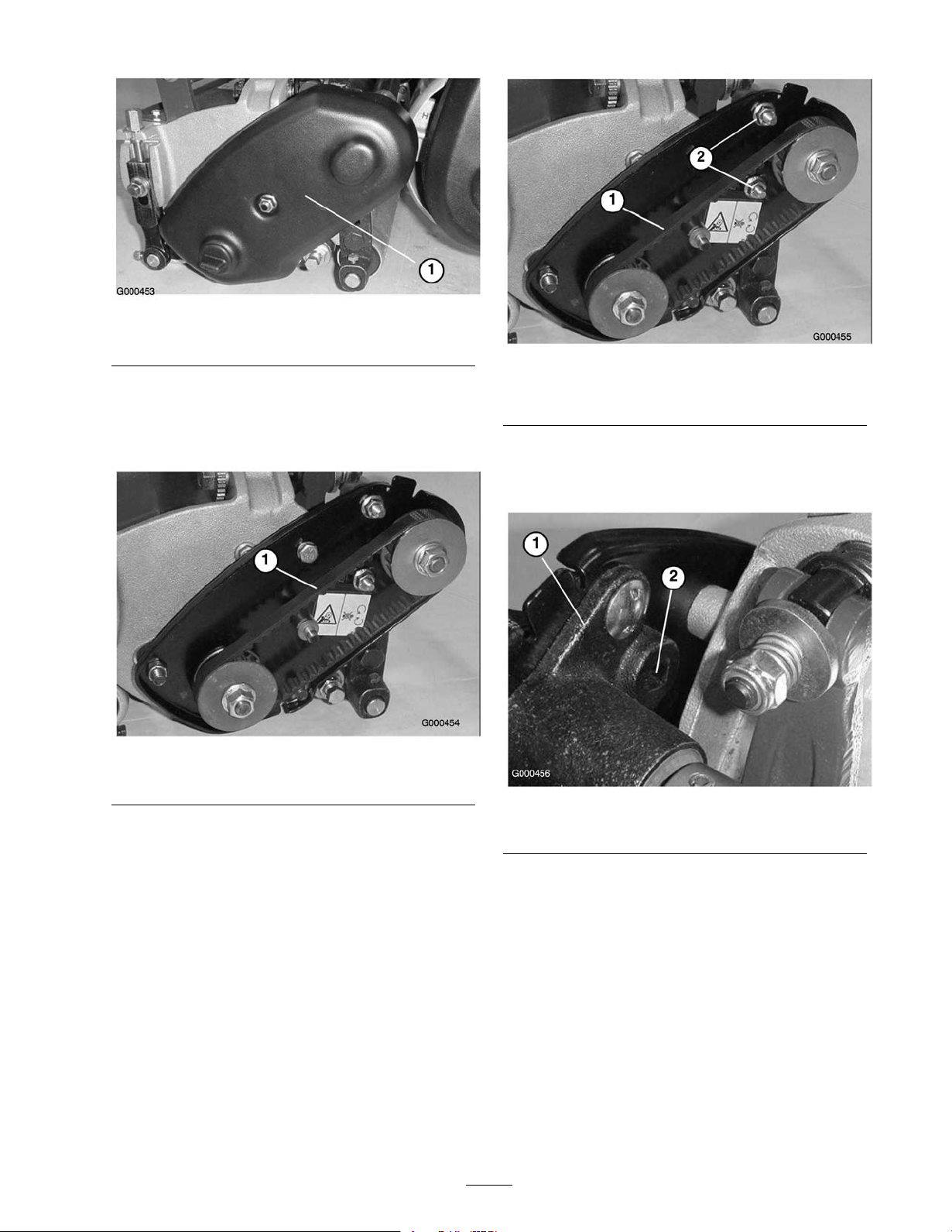
Figure 30
1. Belt cover
2. Chec k tension b y de pressing belt ( Figure 31 ) at
mid span of pulleys with 4 ± 1 lb . of force . Belt
should deflect 1/4 in. If deflection is incor rect,
proceed to next ste p .
Figure 31
1. Reel drive belt
3. T o adjust belt tension:
Figure 32
1. Reel drive belt 2. Bearing housing mounting
nuts
B . Using a 3/8 in. dri v e tor que wrenc h, rotate the
bearing housing with 35-40 in.-lb . of tor que to
set belt tension ( Figure 33 )
Figure 33
1. Bearing housing 2. 3/8" Torque wrench here
A. Loosen the bearing housing mounting n uts
( Figure 32 ).
C . Tighten the bearing housing mounting n uts
( Figure 32 ). Do not o v er -tension belt.
D . Install belt co v er .
Reel Drive Belt (Transmission coupler)
1. R emo v e the belt co v er mounting fasteners and belt
co v er to expose belt ( Figure 34 ).
25
Page 26
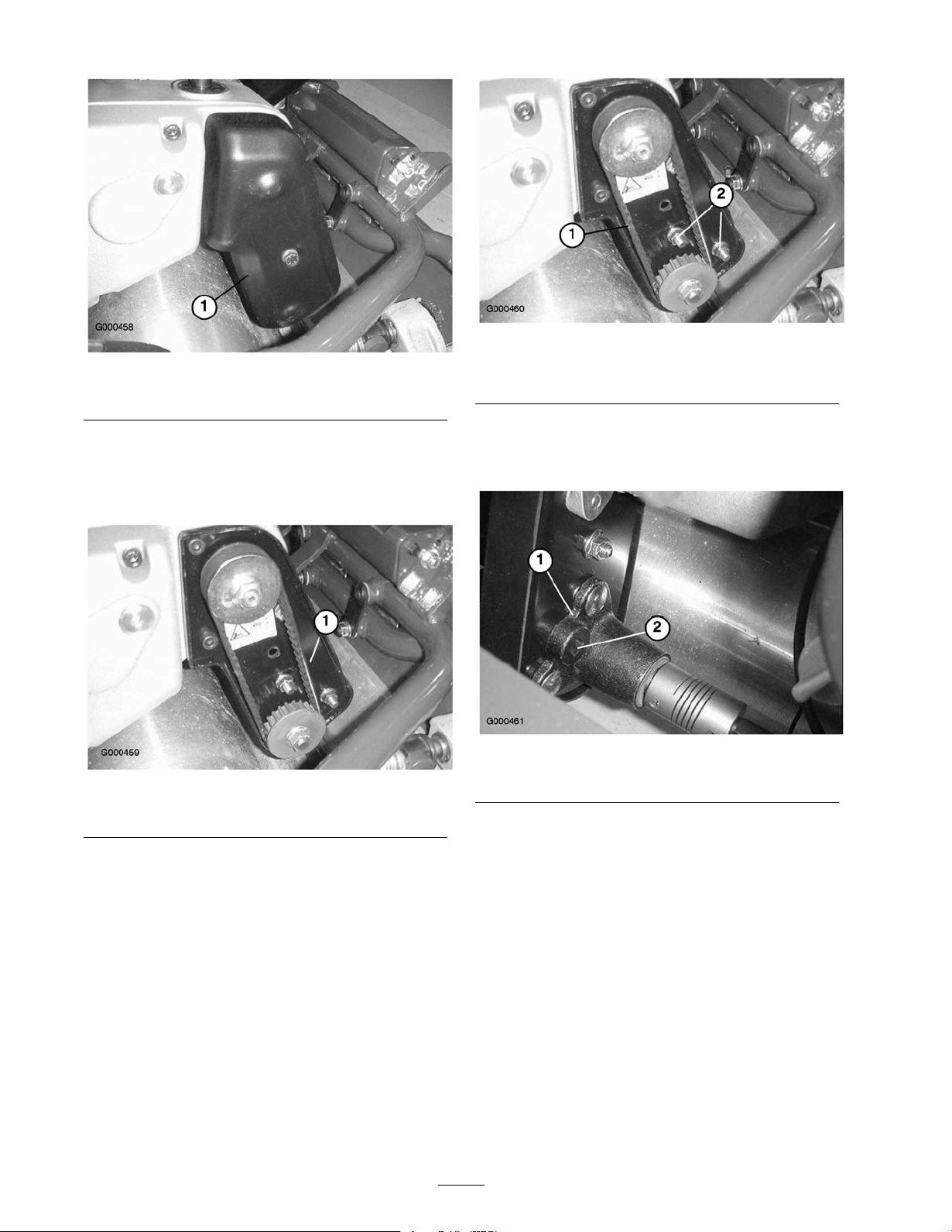
Figure 34
1. Belt cover
2. Chec k tension b y de pressing belt ( Figure 35 ) at
mid span of pulleys with 4 ± 1 lb . of force . Belt
should deflect 1/4 in. If deflection is incor rect,
proceed to next ste p .
Figure 35
1. Reel drive belt
3. T o adjust belt tension:
A. Loosen the bearing housing mounting n uts
( Figure 36 ).
Figure 36
1. Reel drive belt 2. Bearing housing mounting
nuts
B . Using a 3/8 in. dri v e tor que wrenc h, rotate the
bearing housing with 35-40 in.-lb . of tor que to
set belt tension ( Figure 37 ).
Figure 37
1. Bearing housing 2. 3/8" Torque wrench here
C . Tighten the bearing housing mounting n uts
( Figure 36 ). Do not o v er -tension belt.
D . Install belt co v er .
Traction Drive Belt
1. R emo v e belt co v er mounting fasteners and belt
co v er to expose belt ( Figure 38 ).
26
Page 27
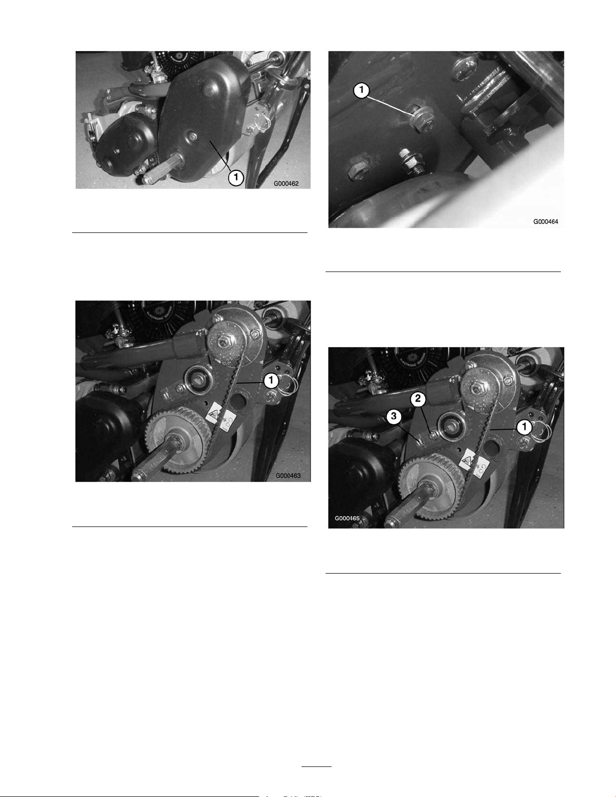
1. Traction drive belt cover
Figure 38
2. Chec k tension b y de pressing belt ( Figure 39 ) at
mid span of pulleys with 4 ± 1 lb . of force . Belt
should deflect 1/4 in. If deflection is incor rect,
proceed to next ste p .
Figure 39
1. Traction drive belt
Figure 40
1. Idler bracket capscrew
B . Using a 3/8 in. dri v e tor que wrenc h, rotate
the idler brac k et with 35-40 in.-lb . of tor que
to set belt tension ( Figure 41 ). Tighten the
idler brac k et mounting capscrew . Do not
o v er -tension belt.
3. T o adjust belt tension:
A. On bac k side of side plate , loosen the capscrew
securing the idler brac k et to the side plate
( Figure 40 ).
Figure 41
1. Traction drive belt 2. Torque here
C . Install belt co v er .
Controls System
Maintenance
Adjusting the Traction
Control
If traction control does not eng ag e or it slips during
operation, an adjustment is required.
27
Page 28
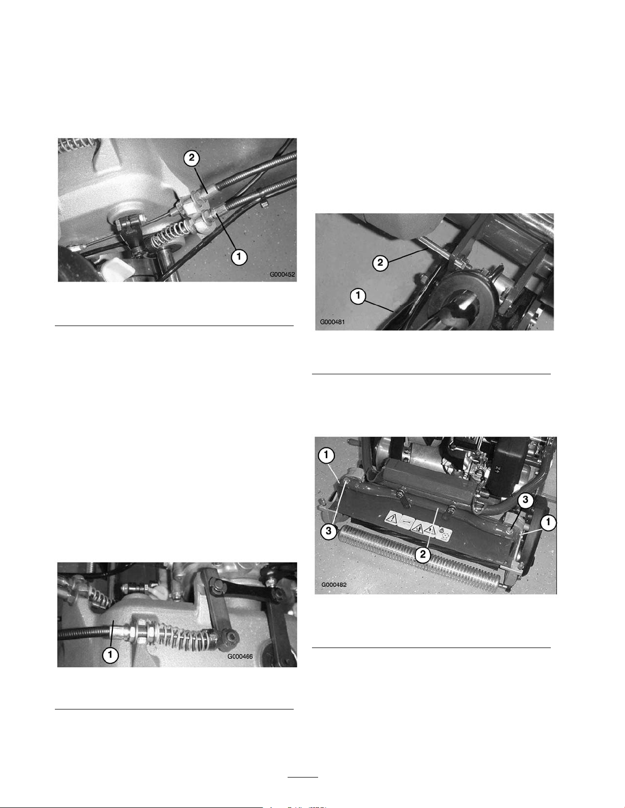
1. Mo v e traction control to Diseng ag ed position.
2. T o increase cable tension, loosen front cable jam
n ut and tighten bac k cable jam n ut ( Figure 42 )
until a force of 12-16 lb . is required to eng ag e
traction control.
Measure the force at the control knob .
Figure 42
1. Traction cable 2. Service/parking brake cable
Cutting Unit
Maintenance
Separating the Cutting Unit
from the Traction Unit
1. Place the mo w er on its dr ums on a lev el surface .
2. Lo w er kic k stand. Inser t a 1/4" dia. pin or
equi v alent into frame hole abo v e kic k stand
mounting bolt ( Figure 44 ).
3. Tighten front cable jam n ut.
4. Chec k control operation.
Adjusting the Reel Control
If reel control does not eng ag e or it slips during
operation, an adjustment is required.
1. Mak e sure traction control is properly adjusted;
refer to Adjusting the T raction Control, pag e .
2. T o increase cable tension, loosen front cable jam
n ut and tighten bac k cable jam n ut ( Figure 43 )
(located on top of g ear bo x) until the reel cable
force adds 7 to 10 lbs . of additional handle force
measured at the control knob .
Note: If traction control handle force is 12 lbs .,
the combined traction and reel force should be 19
to 22 lbs .
Figure 44
1. Kick stand 2. 1/4" Pin
3. R emo v e g rass bask et.
4. R emo v e (2) capscrews securing cutting unit pi v ot
ar ms to traction unit frame tube ( Figure 45 ).
Figure 45
1. Cutting unit pivot arms
2. Traction unit frame tube
3. Capscrews
Figure 43
1. Reel control cable
3. Tighten front cable jam n ut.
4. Chec k control operation.
5. R otate pi v ot ar ms forw ard ( Figure 45 ) and rest
traction unit on restrained kic kstand.
6. Pull cutting unit forw ard about 2 in. (51 mm) and
then to the right to diseng ag e the transmission
coupling ( Figure 46 ).
28
Page 29
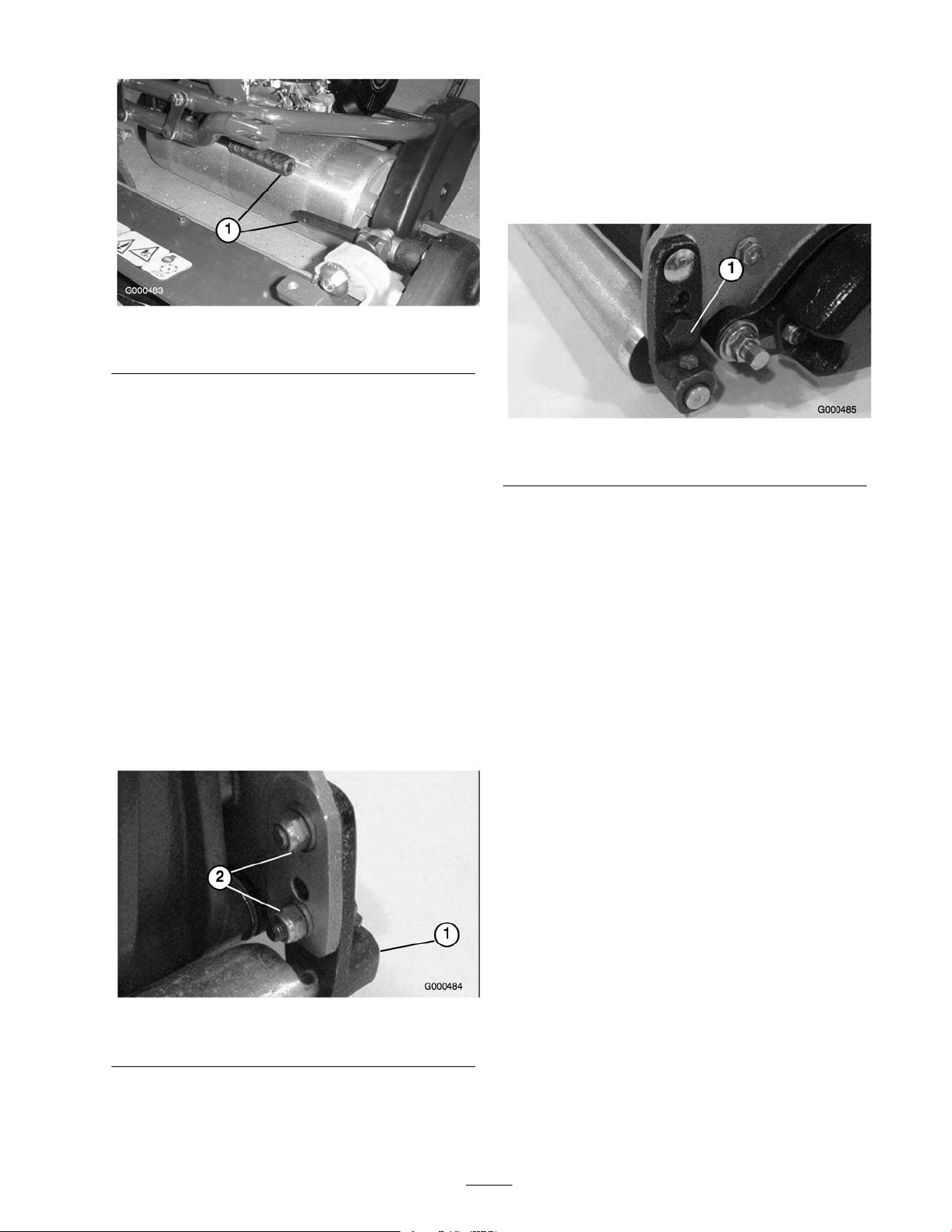
Figure 46
1. Transmission coupling
7. R ev erse procedure to install cutting unit.
T his mounting bolt has an offset, whic h when
rotated, acts as an eccentric (cam) to raise or lo w er
the roller . T here is an I.D . dot whic h denotes the
offset of the bolt. Dot indicates in whic h direction
right end of roller mo v es when bolt is tur ned and
should alw a ys be in the rear half of the arc as
sho wn in Figure 48 .
Leveling the Rear Roller to
the Reel
1. P osition cutting unit on a flat, lev el surface
preferably a precision g round surface plate .
2. Place a 1/4 in. (6.4 mm) or thic k er plate under the
reel blades and ag ainst front edg e of bedknife .
Note: Be sure the plate co v ers the full length of
the reel blades and three blades contact.
3. Fir mly press do wn on cutting unit and maintain
pressure on rear roller . T r y inser ting a piece of
paper under eac h end of the roller . If the g ap is
g reater than the piece of paper , on either end, an
adjustment ma y be required, proceed to ste p 4 .
4. Loosen loc kn uts securing right rear roller brac k et
to cutting unit side plate ( Figure 47 ).
Figure 48
1. Eccentric bolt
Note: If additional adjustment is required, re place
the screw on the left-hand brac k et with another
eccentric bolt, P ar t No . 105-3833. Ensure both
rear roller brac k ets are in the same hole .
6. T o v erify if roller is lev el, tr y inser ting a piece of
paper under eac h end of roller .
7. W hen roller is lev el, tighten n uts securely .
Adjusting the Bedknife to
the Reel
Bedknife to reel adjustment is accomplished b y
loosening or tightening bedbar adjusting screws ,
located on top of mo w er .
1. P osition mac hine on a flat, lev el w ork surface .
2. Mak e sure reel contact is remo v ed b y tur ning
bedbar adjusting screws countercloc kwise
( Figure 49 ).
Figure 47
1. Right rear roller bracket 2. Locknuts
5. W hile holding reel securely on plate and
maintaining pressure on rear roller , rotate lo w er
right roller mounting bolt ( Figure 48 ).
29
Page 30
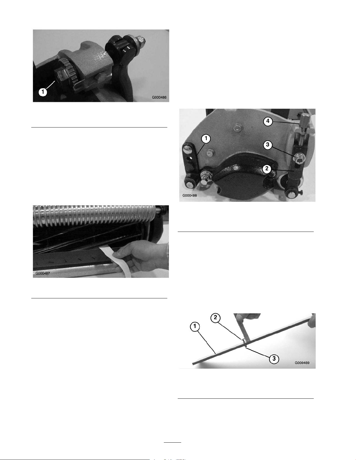
Figure 49
1. Bedbar adjusting screw
3. Tilt mo w er on bac k to expose bedknife and reel.
4. At one end of reel, inser t a long strip of newspaper
betw een reel and bedknife ( Figure 50 ). W hile
slo wly rotating reel forw ard, tur n bedbar adjusting
screw cloc kwise (on same end of reel) ( Figure 49 ),
one clic k at a time , until paper is pinc hed lightly ,
when inser ted from the front, parallel to the
bedknife . A slight drag will be noted as the paper
is pulled.
Adjusting the Height of Cut
1. Adjust rear roller brac k ets ( Figure 51 ) to upper
or lo w er position de pending on desired height of
cut rang e .
• T he upper position (factor y setting) is used
when height of cut settings rang e from 1/16
to 5/32".
• T he lo w er position is used when height of cut
settings rang e from 1/8" to 19/64".
Figure 50
Note: Eac h time adjusting screw is rotated one
clic k cloc kwise , bedknife mo v es .0007 in. closer to
reel. Do not o v er tighten the adjusting screws .
5. Chec k for light contact at other end of reel using
paper and adjust as required.
6. After adjustment is accomplished, c hec k to see if
reel can pinc h paper when inser ted from the front
and cut paper when inser ted at a right angle to the
bedknife ( Figure 50 ). It should be possible to cut
paper with minim um contact betw een the bedknife
and the reel blades . Should ex cessi v e reel drag
be evident it will be either necessar y to bac klap
or reg rind the cutting unit to ac hiev e the shar p
edg es needed for precision cutting (see T oro reel
shar pening man ual).
Figure 51
1. Rear roller bracket 3. Locknut
2. Height-of-cut arm 4. Adjusting screw
2. V erify that rear roller is lev el and that bedknife
to reel contact is cor rect. Tip mo w er on bac k to
expose front and rear rollers and bedknife .
3. Loosen loc kn uts securing height-of-cut ar ms to
cutting unit side plates ( Figure 51 ).
4. Loosen n ut on g aug e bar ( Figure 52 ) and set
adjusting screw to desired height-of-cut. Distance
betw een bottom of screw head and face of bar is
height-of-cut.
Figure 52
1. Gauge bar
2. Height adjusting screw
3. Nut
5. Hook screw head on cutting edg e of bedknife and
rest rear end of bar on rear roller ( Figure 53 ).
30
Page 31
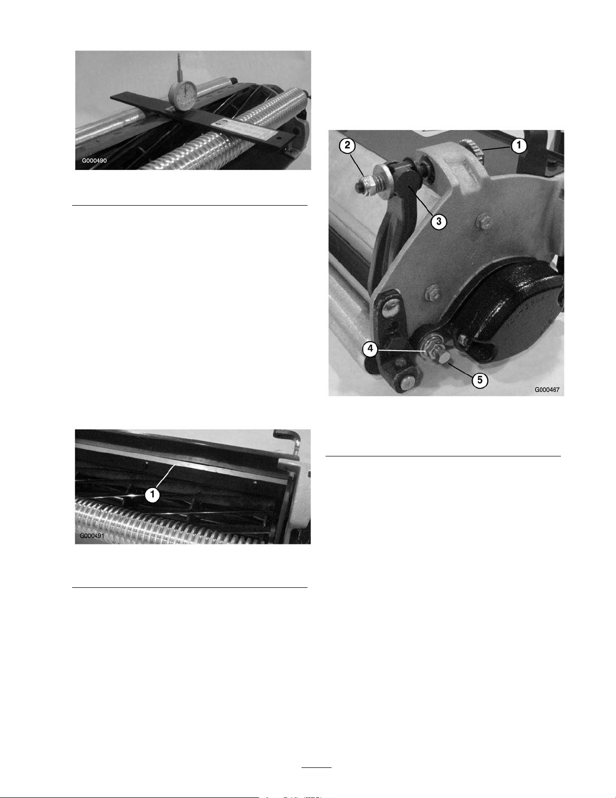
Figure 53
6. R otate adjusting screw until roller contacts front of
g aug e bar . Adjust both ends of roller until entire
roller is parallel to the bedknife .
Important: W hen set pr oper l y , the r ear and
fr ont r oller s will contact the gauge bar and the
scr ew will be sn ug a gainst the bedknife. T his
ensur es that the height-of-cut is identical at
both ends of the bedknife.
7. Tighten n uts to secure adjustment.
Servicing the Bedbar
Removing the Bedbar
1. T ur n bedbar adjuster screw , countercloc kwise , to
bac k bedknife a w a y from reel ( Figure 55 ).
Adjusting the Cut-Off Bar
Adjust cut-off bar to assure clippings are cleanly
disc harg ed from the reel area:
1. Loosen screws securing top bar ( Figure 54 ) to
cutting unit.
Figure 54
1. Cut-off bar
2. Inser t .060 inc h feeler g aug e betw een top of reel
and bar and tighten screws . Ensure bar and reel are
equal distance apar t across complete reel.
Note: T he bar is adjustable to compensate for
c hang es in turf conditions . T he bar should be
adjusted closer to reel when turf is extremely dr y .
By contrast, adjust bar fur ther a w a y from reel when
turf conditions are w et. T he bar should be parallel
to reel to ensure optim um perfor mance and should
be adjusted whenev er reel is shar pened on a reel
g rinder .
Figure 55
1. Bedbar adjusting screw
2. Spring tension nut
3. Bedbar
4. Jam nut
5. Bedbar bolt
2. Bac k out the spring tension n ut, until the w asher is
no long er tensioned ag ainst the bedbar ( Figure 55 ).
3. On eac h side of the mac hine , loosen the jam n ut
securing the bedbar bolt ( Figure 55 ).
4. R emo v e eac h bedbar bolt allo wing bedbar to be
pulled do wnw ard and remo v ed from mac hine .
Account for 2 nylon and 2 stamped steel w ashers
on eac h end of bedbar ( Figure 55 ).
Assembling the Bedbar
1. Install bedbar , positioning mounting ears betw een
w asher and bedbar adjuster .
2. Secure bedbar to eac h side plate with bedbar bolts
(jam n uts on bolts) and 8 w ashers . A nylon w asher
is to be positioned on eac h side of side plate boss .
Place a steel w asher outside eac h of the nylon
w ashers . T or que bolts to 240-320 in.-lb .
3. Tighten the jam n ut until the end pla y is remo v ed
from the outside thr ust w ashers . Do not
o v er tighten.
31
Page 32
Note: It is acce ptable that the inside thr ust
w ashers on the cutting unit ma y remain loose .
4. Tighten spring tension n ut until spring is collapsed,
then bac k off 1/2 tur n.
5. Adjust bedbar; refer to Adjusting the Bedknife to
the R eel.
Backlapping the Reel
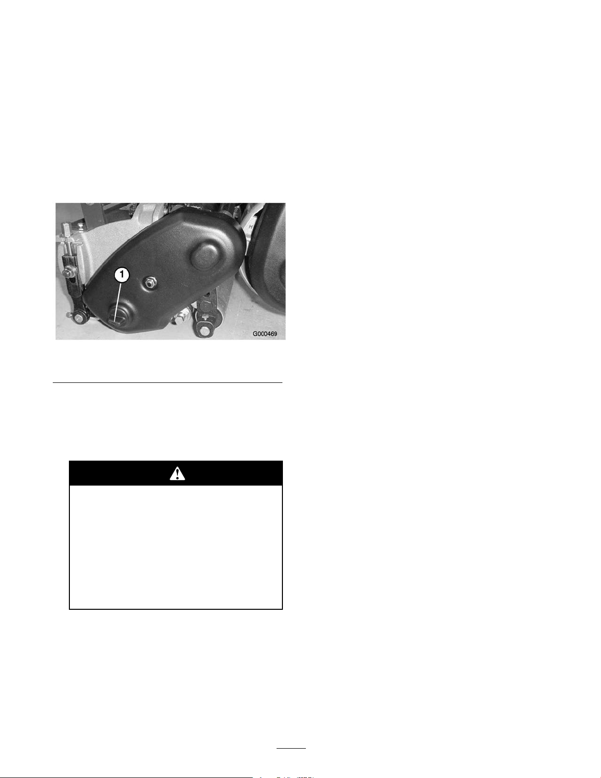
1. R emo v e plug from the reel dri v e co v er on the left
side of reel assembly ( Figure 56 )
Figure 56
1. Reel drive cover plug
2. Inser t a 18 mm soc k et onto hex flang e n ut on left
end of reel shaft.
3. Bac klap according to procedure in T oro Shar pening
R eel and R otar y Mo w ers Man ual, F or m No . 80-300
PT .
Contact with the r eel or other mo ving par ts
can r esult in per sonal injur y .
• Stay a w ay fr om the r eel while
backlapping .
• Nev er use a shor t handled paint br ush f or
backlapping . P ar t No. 29-9100 Handle
assembl y complete or indi vidual par ts
ar e a v aila ble fr om y our local Authoriz ed
T or o Distributor .
Note: F or a better cutting edg e , r un a file across
the front face of the bedknife when the lapping
operation is completed. T his will remo v e any bur rs
or rough edg es that ma y ha v e built up on the
cutting edg e .
4. R einstall plug when bac klap operation is completed.
32
Page 33

Storage
1. R emo v e g rass clippings , dir t, and g rime from the
exter nal par ts of the entire mac hine , especially the
engine . Clean dir t and c haff from the outside of
the engine’ s cylinder head fins and blo w er housing .
Important: Y ou can w ash the machine with
mild detergent and w ater . Do not pr essur e
w ash the machine. A v oid ex cessi v e use of
w ater , especiall y near the shift lev er plate, and
engine.
2. F or long-ter m storag e (more than 90 da ys) add
stabilizer/conditioner additi v e to fuel in the tank.
A. R un the engine to distribute conditioned fuel
through the fuel system (5 min utes).
B . Either stop engine , allo w it to cool, and drain
the fuel tank, or operate the engine until it
stops .
C . R estar t the engine and r un it until it stops .
R e peat, on Chok e , until the engine will not
restar t.
D . Dispose of fuel properly . R ecycle as per local
codes .
Note: Do not store stabilizer/conditioned
g asoline o v er 90 da ys .
3. Chec k and tighten all bolts , n uts , and screws . R e pair
or re place any par t that is damag ed or defecti v e .
4. P aint all scratc hed or bare metal surfaces . P aint is
a v ailable from y our A uthorized Ser vice Dealer .
5. Store the mac hine in a clean, dr y g arag e or storag e
area. Co v er the mac hine to protect it and k ee p it
clean.
33
Page 34

Notes:
Page 35

Notes:
Page 36

The Toro General Commercial Products Warranty
A Two-Year Limited Warranty
Conditions and Products Covered
The Toro Company and its afliate, Toro Warranty Company,
pursuant to an agreement between them, jointly warrant your
Toro Commercial Product (“Product") to be free from defects
in materials or workmanship for two years or 1500 operational
hours*, whichever occurs rst. Where a warrantable condition
exists, we will repair the Product at no cost to you including
diagnosis, labor, parts, and transportation. This warranty
begins on the date the Product is delivered to the original retail
purchaser.
* P r o d u c t e q u i p p e d w i t h h o u r m e t e r
Instructions for Obtaining Warranty Service
You are responsible for notifying the Commercial Products
Distributor or Authorized Commercial Products Dealer from
whom you purchased the Product as soon as you believe a
warrantable condition exists.
If you need help locating a Commercial Products Distributor
or Authorized Dealer, or if you have questions regarding your
warranty rights or responsibilities, you may contact us at:
Toro Commercial Products Service Department
Toro Warranty Company
8111 Lyndale Avenue South
Bloomington, MN 55420-1196
952-888-8801 or 800-982-2740
E-mail: [email protected]
Owner Responsibilities
As the Product owner, you are responsible for required
maintenance and adjustments stated in your operator’s manual.
Failure to perform required maintenance and adjustments can be
grounds for disallowing a warranty claim.
Items and Conditions Not Covered
Not all product failures or malfunctions that occur during the
warranty period are defects in materials or workmanship. This
express warranty does not cover the following:
• Product failures which result from the use of non-Toro
replacement parts, or from installation and use of add-on,
modied, or unapproved accessories
• Product failures which result from failure to perform required
maintenance and/or adjustments
• Product failures which result from operating the Product in
an abusive, negligent or reckless manner
• Parts subject to consumption through use unless found to be
defective. Examples of parts which are consumed, or used
up, during normal Product operation include, but are not
limited to, blades, reels, bedknives, tines, spark plugs, castor
wheels, tires, lters, belts, and certain sprayer components
such as diaphragms, nozzles, and check valves, etc.
• Failures caused by outside inuence. Items considered to be
outside inuence include, but are not limited to, weather,
storage practices, contamination, use of unapproved
coolants, lubricants, additives, or chemicals, etc.
• Normal “wear and tear" items. Normal “wear and tear"
includes, but is not limited to, damage to seats due to wear
or abrasion, worn painted surfaces, scratched decals or
windows, etc.
Parts
Parts scheduled for replacement as required maintenance are
warranted for the period of time up to the scheduled replacement
time for that part.
Parts replaced under this warranty become the property of
Toro. Toro will make the nal decision whether to repair any
existing part or assembly or replace it. Toro may use factory
remanufactured parts rather than new parts for some warranty
repairs.
General Conditions
Repair by an Authorized Toro Distributor or Dealer is your sole
remedy under this warranty.
Neither The Toro Company nor Toro Warranty Company
is liable for indirect, incidental or consequential
damages in connection with the use of the Toro
Products covered by this warranty, including any cost or
expense of providing substitute equipment or service
during reasonable periods of malfunction or non-use
pending completion of repairs under this warranty.
Except for the Emissions warranty referenced below,
if applicable, there is no other express warranty. All
implied warranties of merchantability and tness for
use are limited to the duration of this express warranty.
Some states do not allow exclusions of incidental or consequential
damages, or limitations on how long an implied warranty lasts,
so the above exclusions and limitations may not apply to you.
This warranty gives you specic legal rights, and you may also
have other rights which vary from state to state.
Note regarding engine warranty: The Emissions Control System
on your Product may be covered by a separate warranty meeting
requirements established by the U.S. Environmental Protection
Agency (EPA) and/or the California Air Resources Board (CARB).
The hour limitations set forth above do not apply to the Emissions
Control System Warranty. Refer to the Engine Emission Control
Warranty Statement printed in your operator’s manual or
contained in the engine manufacturer’s documentation for
details.
Countries Other than the United States or Canada
Customers who have purchased Toro products exported from the United States or Canada should contact their Toro Distributor
(Dealer) to obtain guarantee policies for your country, province, or state. If for any reason you are dissatised with your Distributor’s
service or have difculty obtaining guarantee information, contact the Toro importer. If all other remedies fail, you may contact us
at Toro Warranty Company.
374-0031 Rev C
 Loading...