

Toro Greensmaster 1021, Greensmaster 1026, Greensmaster 1018, Greensmaster 04830, Greensmaster 04840 Operator's Manual
...Page 1
FormNo.3433-327RevB
Greensmaster
®
1018,1021,or
1026Mower
ModelNo.04820—SerialNo.400000000andUp
ModelNo.04830—SerialNo.400000000andUp
ModelNo.04840—SerialNo.400000000andUp
Registeratwww.T oro.com.
OriginalInstructions(EN)
*3433-327*B
Page 2
ThisproductcomplieswithallrelevantEuropean
directives;fordetails,pleaseseetheseparateproduct
specicDeclarationofConformity(DOC)sheet.
ItisaviolationofCaliforniaPublicResourceCode
Section4442or4443touseoroperatetheengineon
anyforest-covered,brush-covered,orgrass-covered
landunlesstheengineisequippedwithaspark
arrester,asdenedinSection4442,maintainedin
effectiveworkingorder,ortheengineisconstructed,
equipped,andmaintainedforthepreventionofre.
Theenclosedengineowner'smanualissupplied
forinformationregardingtheUSEnvironmental
ProtectionAgency(EPA)andtheCaliforniaEmission
ControlRegulationofemissionsystems,maintenance,
andwarranty.Replacementsmaybeorderedthrough
theenginemanufacturer.
Operatingthismachine1,500m(5,000ft)above
sealevelrequiresahigh-altitudejet.Refertoyour
Hondaengineowner’smanual.
WARNING
Wheneveryouneedservice,genuineToroparts,or
additionalinformation,contactanAuthorizedService
DealerorToroCustomerServiceandhavethemodel
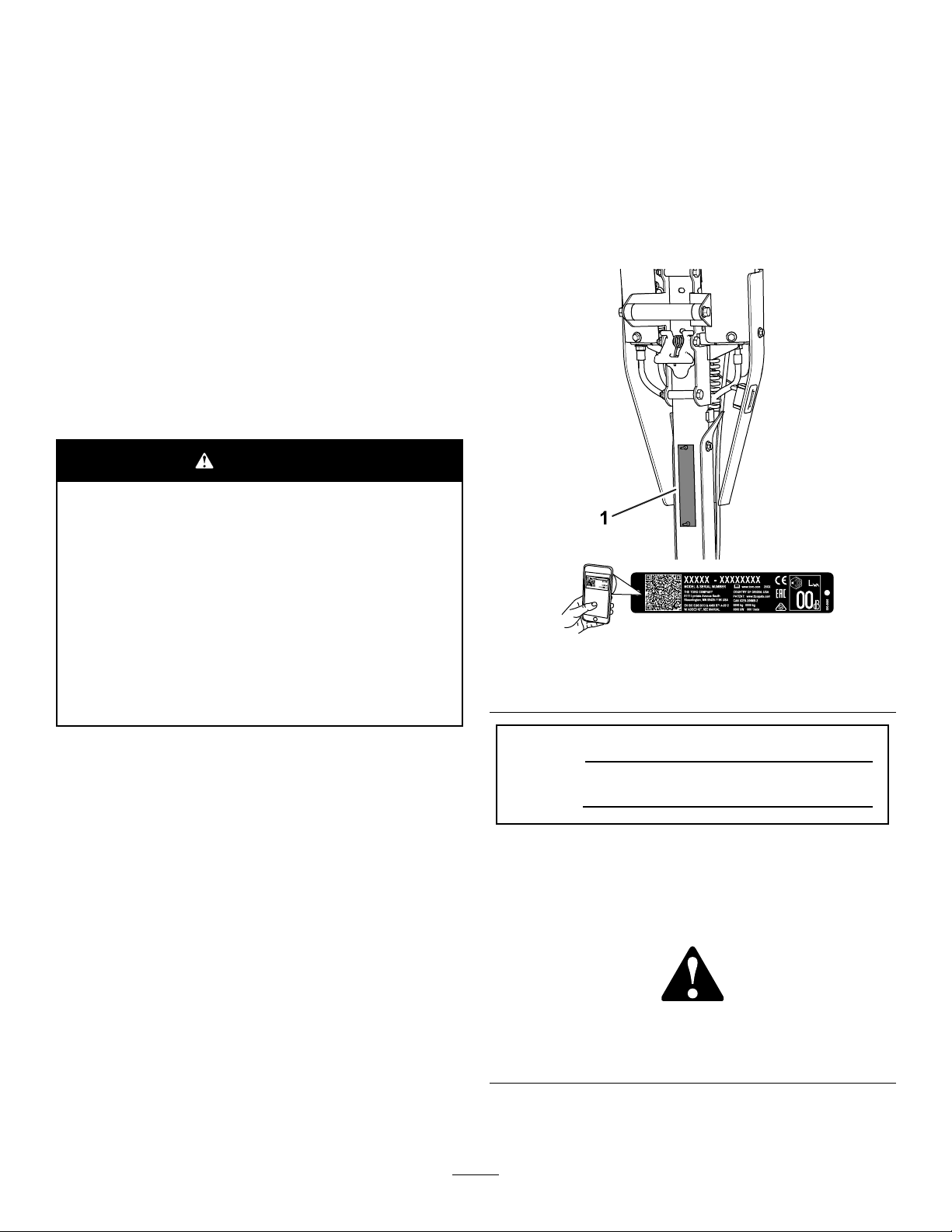
andserialnumbersofyourproductready.Figure1
identiesthelocationofthemodelandserialnumbers
ontheproduct.Writethenumbersinthespace
provided.
Important:Withyourmobiledevice,youcan
scantheQRcode(ifequipped)ontheserial
numberdecaltoaccesswarranty,parts,andother
productinformation.
CALIFORNIA
Proposition65Warning
Theengineexhaustfromthisproduct
containschemicalsknowntotheStateof
Californiatocausecancer,birthdefects,
orotherreproductiveharm.
Useofthisproductmaycauseexposure
tochemicalsknowntotheStateof
Californiatocausecancer,birthdefects,
orotherreproductiveharm.
Introduction
Thismachineisawalk-behind,reel-bladelawnmower
intendedtobeusedbyprofessional,hiredoperators
incommercialapplications.Itisprimarilydesigned
forcuttinggrassonwell-maintainedturf.Usingthis
productforpurposesotherthanitsintendedusecould
provedangeroustoyouandbystanders.
g271512
Figure1
1.Modelandserialnumberlocation
ModelNo.
SerialNo.
Thismanualidentiespotentialhazardsandhas
safetymessagesidentiedbythesafety-alertsymbol
(Figure2),whichsignalsahazardthatmaycause
seriousinjuryordeathifyoudonotfollowthe
recommendedprecautions.
Readthisinformationcarefullytolearnhowtooperate
andmaintainyourproductproperlyandtoavoid
injuryandproductdamage.Youareresponsiblefor
operatingtheproductproperlyandsafely .
Visitwww.Toro.comforproductsafetyandoperation
trainingmaterials,accessoryinformation,helpnding
adealer,ortoregisteryourproduct.
©2019—TheToro®Company
8111LyndaleAvenueSouth
Bloomington,MN55420
Safety-alertsymbol
Thismanualuses2wordstohighlightinformation.
Importantcallsattentiontospecialmechanical
2
g000502
Figure2
Contactusatwww.Toro.com.
PrintedintheUSA
AllRightsReserved
Page 3

informationandNoteemphasizesgeneralinformation
worthyofspecialattention.
Contents
Safety.......................................................................4
GeneralSafety...................................................4
SafetyandInstructionalDecals..........................4
Setup........................................................................6
1AdjustingandInstallingtheCutting
Unit.................................................................6
2InstallingtheTransportWheelShafts...............6
3InstallingtheTransportWheels........................7
4InstallingtheGrassBasket..............................8
ProductOverview.....................................................8
Controls.............................................................9
Specications...................................................11
Attachments/Accessories..................................11
BeforeOperation.................................................12
BeforeOperationSafety...................................12
PerformingDailyMaintenance..........................12
CheckingtheEngine-OilLevel..........................12
FuelSpecications...........................................12
FillingtheFuelTank..........................................13
AdjustingtheClipRate.....................................13
AdjustingtheReelSpeed.................................13
AdjustingtheTraction-DrumPosition................14
AdjustingtheHandleHeight.............................14
TransportingtheMachinetoaJob
Site................................................................14
RemovingtheTransportWheels.......................15
UsingtheChokeLever.....................................15
OpeningandClosingtheFuel-Shutoff
Valve.............................................................16
DuringOperation.................................................16
DuringOperationSafety...................................16
StartingtheEngine...........................................17
OperatingTips..................................................18
ShuttingOfftheEngine.....................................19
AfterOperation....................................................19
AfterOperationSafety......................................19
OperatingtheControlsafterMowing.................19
TransportingtheMachine.................................19
InstallingtheTransportWheels.........................19
EngagingorDisengagingthe
Transmission................................................20
Maintenance...........................................................21
MaintenanceSafety..........................................21
RecommendedMaintenanceSchedule(s)...........21
DailyMaintenanceChecklist.............................22
Pre-MaintenanceProcedures..............................23
PreparingtheMachineforMaintenance............23
EngineMaintenance...........................................23
EngineSafety...................................................23
ServicingtheEngineOil....................................23
ServicingtheAirCleaner..................................24
ServicingtheSparkPlug...................................25
ControlsSystemMaintenance.............................26
AdjustingtheTractionCable.............................26
AdjustingtheService/ParkingBrake.................27
TighteningtheHandle-Isolation
Hardware......................................................28
CuttingUnitMaintenance.....................................28
BladeSafety.....................................................28
InstallingtheCuttingUnit..................................28
RemovingtheCuttingUnit................................29
BacklappingtheCuttingUnit.............................30
Storage...................................................................30
StorageSafety..................................................30
StoringtheMachine..........................................30
3
Page 4
Safety
Thismachinehasbeendesignedinaccordancewith
ENISO5395andANSIB71.4-2017.
GeneralSafety
Thisproductiscapableofamputatinghandsandfeet
andofthrowingobjects.
•Readandunderstandthecontentsofthis
Operator’sManualbeforestartingthemachine.
•Useyourfullattentionwhileoperatingthe
machine.Donotengageinanyactivitythat
causesdistractions;otherwise,injuryorproperty
damagemayoccur.
•Donotputyourhandsorfeetnearmoving
componentsofthemachine.
SafetyandInstructionalDecals
•Donotoperatethemachinewithoutallguards
andothersafetyprotectivedevicesinplaceand
functioningproperlyonthemachine.
•Keepbystandersandchildrenoutoftheoperating
area.Neverallowchildrentooperatethemachine.
•Shutofftheengine,removethekey(ifequipped),
andwaitforallmovementtostopbeforeyouleave
theoperator’sposition.Allowthemachinetocool
beforeadjusting,servicing,cleaning,orstoringit.
Improperlyusingormaintainingthismachinecan
resultininjury .T oreducethepotentialforinjury,
complywiththesesafetyinstructionsandalways
payattentiontothesafety-alertsymbol
meansCaution,Warning,orDanger—personalsafety
instruction.Failuretocomplywiththeseinstructions
mayresultinpersonalinjuryordeath.
,which
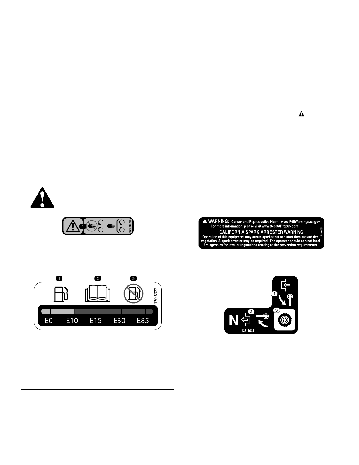
Safetydecalsandinstructionsareeasilyvisibletotheoperatorandarelocatednearanyarea
ofpotentialdanger.Replaceanydecalthatisdamagedormissing.
120-9570
1.Warning—stayawayfrommovingparts,keepallguards
andshieldsinplace.
130-8322
1.Useonlyfuelwithan
alcoholcontentbyvolume
under10%.
2.ReadtheOperator's
Manualformore
informationonfuel.
3.Donotusefuelwithan
alcoholcontentbyvolume
greaterthan10%.
decal120-9570
decal133-8062
133-8062
decal130-8322
138-1644
1.Rotatethehandleto
engage.
2.Withthemachineinthe
Neutralposition,rotatethe
handletodisengage.
3.Transmissioncontrol
decal138-1644
4
Page 5
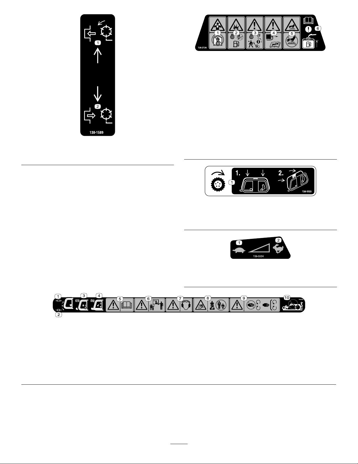
decal138-2138
138-2138
138-1589
1.Engagethereels.2.Disengagethereels.
1.Poisonousfumesor
toxicgases,asphyxiation
hazard—donotrunthe
4.Warning—disconnectthe
sparkplugwirebefore
performingmaintenance.
engineinanenclosed
space.
2.Explosionhazard—shut
offtheenginebefore
5.Hotsurfacehazard—do
nottouchthehotsurface.
addingfuel;nore,open
ames,orsmokingwhen
addingfuel.
decal138-1589
engineandclosethe
fuelshutoffvalvebefore
leavingthemachine.
3.Warning—shutoffthe
6.Attention—readthe
Operator’sManualfor
informationaboutlling
thefueltank.
decal138-5533
138-5533
1.Tractioncontrol—pressthetractioncontroldownthenpull
ittothehandle.
138-5534
1.Slow
2.Fast
138-5532
1.Pulluptoreleasethebrake.6.Warning—donotoperatethismachineunlessyouaretrained.
2.Pulldowntoapplythebrake.7.Warning—wearhearingprotection.
3.Parkingbrake—locked8.Thrownobjecthazard—keepbystandersaway.
4.Parkingbrake—unlocked
5.Warning—readtheOperator’sManual.
9.Warning—stayawayfrommovingparts;keepallguardsand
shieldsinplace.
10.Donottowthemachine.
decal138-5534
decal138-5532
5
Page 6
Setup
LooseParts
Usethechartbelowtoverifythatallpartshavebeenshipped.
ProcedureDescription
1
2
3
4
Cuttingunit(orderseparately;contact
yourauthorizedT orodistributor)
Coupler
Spring
Rightwheelshaft
Leftwheelshaft
TransportWheelKit(orderseparately;
contactyourauthorizedT orodistributor)
Grassbasket
Qty.
1
1
1
1
1
1
1Installthegrassbasket.
MediaandAdditionalParts
Description
Operator'sManual
EngineOwner'sManual
CerticateofCompliance
Note:Determinetheleftandrightsidesofthemachinefromthenormaloperatingposition.
Qty.
1
1
1
Readorviewtheitemsbeforeoperatingthemachine.
Use
Adjustandinstallthecuttingunittothe
machine.
Installthetransportwheelshafts(Model
04840only).
Installthetransportwheels(optional).
Use
1
AdjustingandInstallingthe
CuttingUnit
Partsneededforthisprocedure:
Cuttingunit(orderseparately;contactyourauthorized
1
Torodistributor)
1
Coupler
1
Spring
Procedure
1.Adjustthecuttingunittoyourdesiredsettings;
refertothecuttingunitOperator’sManual.
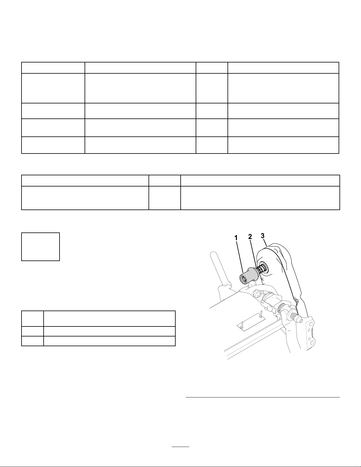
2.Installthecouplerandspringtothe
reel-drive-assemblyofthecuttingunit(Figure3).
Figure3
1.Coupler
2.Spring
3.Installthecuttingunittothemachine;referto
InstallingtheCuttingUnit(page28).
3.Reel-driveassembly
g304658
6
Page 7
2
3
InstallingtheTransport
WheelShafts
Model04840Only
Partsneededforthisprocedure:
1
Rightwheelshaft
1
Leftwheelshaft
Procedure
1.Applythread-lockingcompoundtothethreads
ofthewheelshafts.
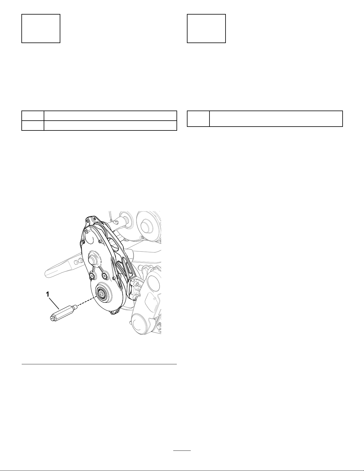
2.Threadtherightwheelshaftintothedrumdrive
assemblyontherightsideofthemachine.
Note:Therightwheelshaftismarkedwitha
“R”ontheshaftendandhasleft-handthreads.
InstallingtheTransport
Wheels
Optional
Partsneededforthisprocedure:
TransportWheelKit(orderseparately;contactyour
1
authorizedTorodistributor)
Procedure
Toinstallthetransportwheels,youmustrstacquire
theTransportWheelKit(ModelNo.04123).Contact
yourauthorizedTorodistributorforthiskit.
1.Installthetransportwheels;refertoInstalling
theTransportWheels(page19).
2.Ensurethatthetiresareinatedto83to103
kPa(12to15psi).
Figure4
1.Rightwheelshaft
3.Torquetheshaftto36to45N∙m(27to33ft-lb).
4.Repeatsteps1through3toinstalltheleftwheel
shafttotheleftsideofthemachine.
g284635
7
Page 8
4
InstallingtheGrassBasket
Partsneededforthisprocedure:
1
Grassbasket
Procedure
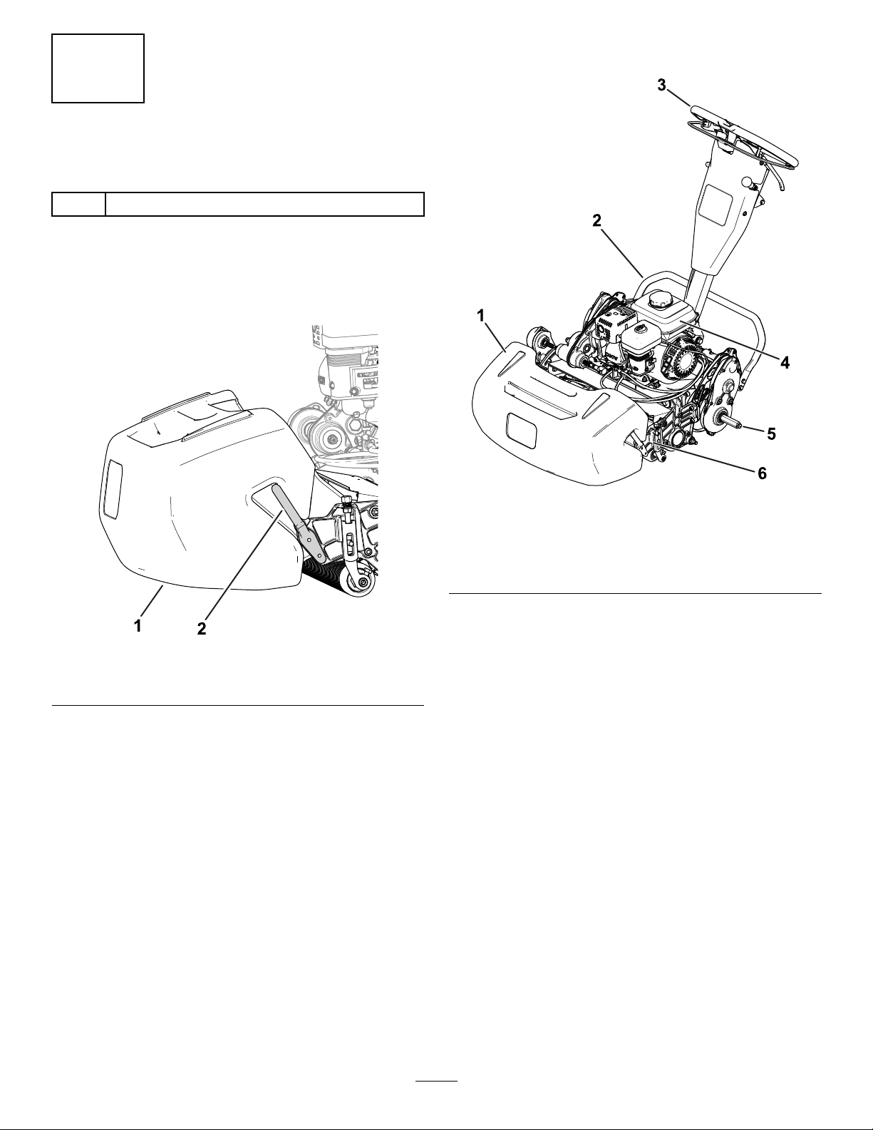
Graspthebasketbythetoplipandslideitontothe
basketmountingrods(Figure5).
ProductOverview
1.Grassbasket
Figure5
2.Basketmountingrod
g274957
Figure6
1.Grassbasket
2.Kickstand5.Transport-wheelaxle
3.Handle
g278331
4.Fueltank
6.Cuttingunit
8
Page 9
Controls
ClutchBail
Usetheclutchbail(Figure7)toengageordisengage
thetractiondrive.
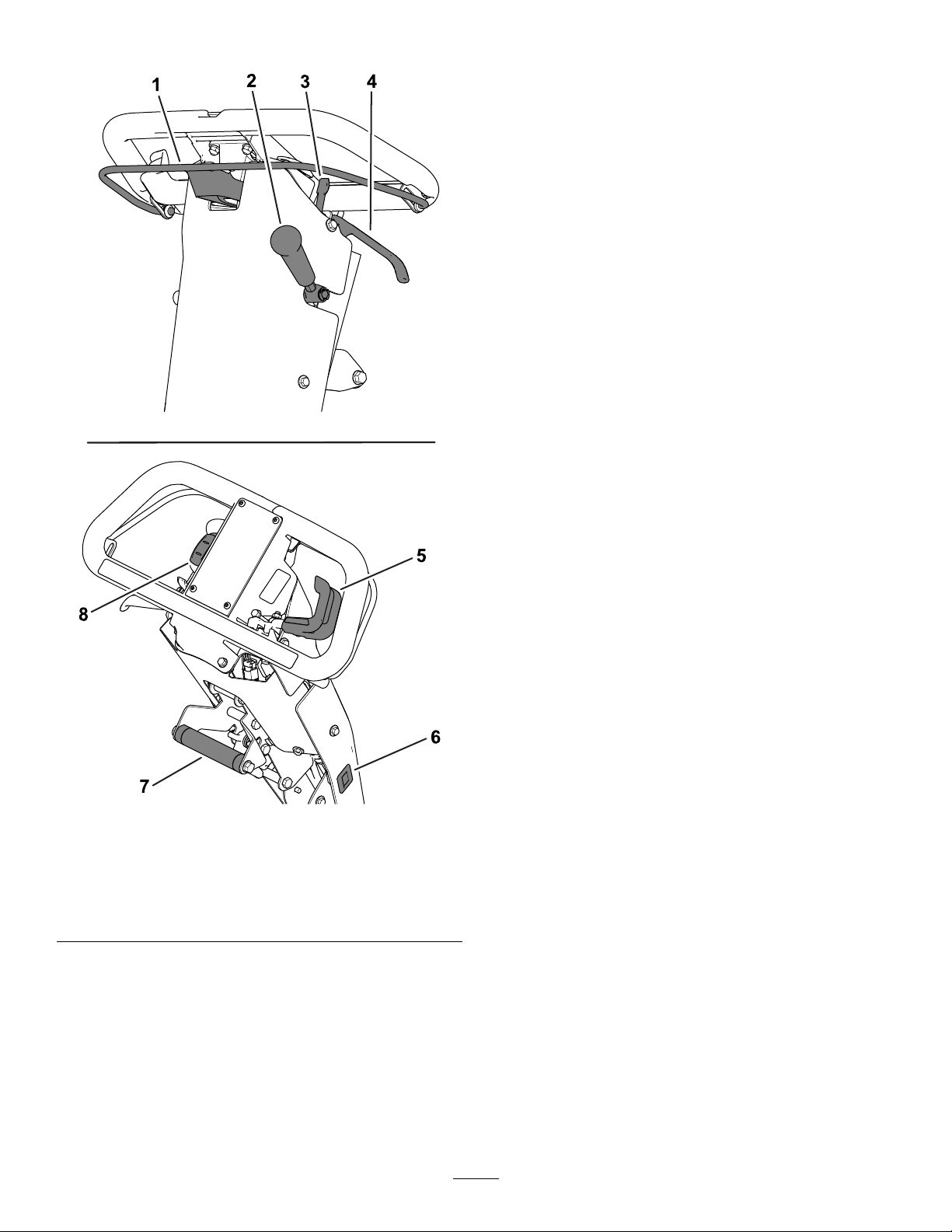
•Engagethetractiondrive:Pullupandholdthe
bartothehandle.
•Disengagethetractiondrive:Releasethebar.
ThrottleControl
Usethethrottlecontrol(Figure7)toadjusttheengine
speed.
•Increasetheenginespeed:Rotatetheleverup.
•Decreasetheenginespeed:Rotatethelever
down.
On/OffSwitch
Theswitch(Figure7)allowsyoutostartorshutoff
theengine.
•Starttheengine:Pushdownontheupperpart
oftheswitch.
•Shutofftheengine:Pushdownonthelowerpart
oftheswitch.
Figure7
1.Clutchbail
2.Cutting-unit-drivelever
3.Parking-brakelatch
4.Service-brakelever8.On/Offswitch
5.Throttlecontrol
6.Hourmeter
7.Lift-assisthandle
Service-BrakeLever
Usetheservicebrake(Figure7)tosloworstopthe
machine.Pullthelevertowardthehandletoengage
theservicebrake.
Parking-BrakeLatch
Usetheparking-brakelatch(Figure7)toengagethe
parkingbrakewhileyouareawayfromthemachine.
•Engagetheparkingbrake:Engageandholdthe
service-brakeleverandrotatetheparking-brake
g271082
latchtowardyou.
•Disengagetheparkingbrake:Pullthe
service-brakelevertowardthehandle.
Cutting-Unit-DriveLever
Usethecutting-unit-drivelever(Figure7)toengage
ordisengagethecuttingunitwhiletheclutchbailis
engaged.
•Engagethecuttingunit:Movetheleverdown.
•Disengagethecuttingunit:Movetheleverup.
HourMeter
Thehourmeter(Figure7)recordsthetotalnumberof
hoursthattheenginehasbeenrunning.Refertothe
meterforschedulingregularmaintenance.
9
Page 10
Lift-AssistHandle
Fuel-ShutoffValve
Usethelift-assisthandle(Figure7)tohelpwith
adjustingthehandleheightorraiseandlowerthe
kickstand.
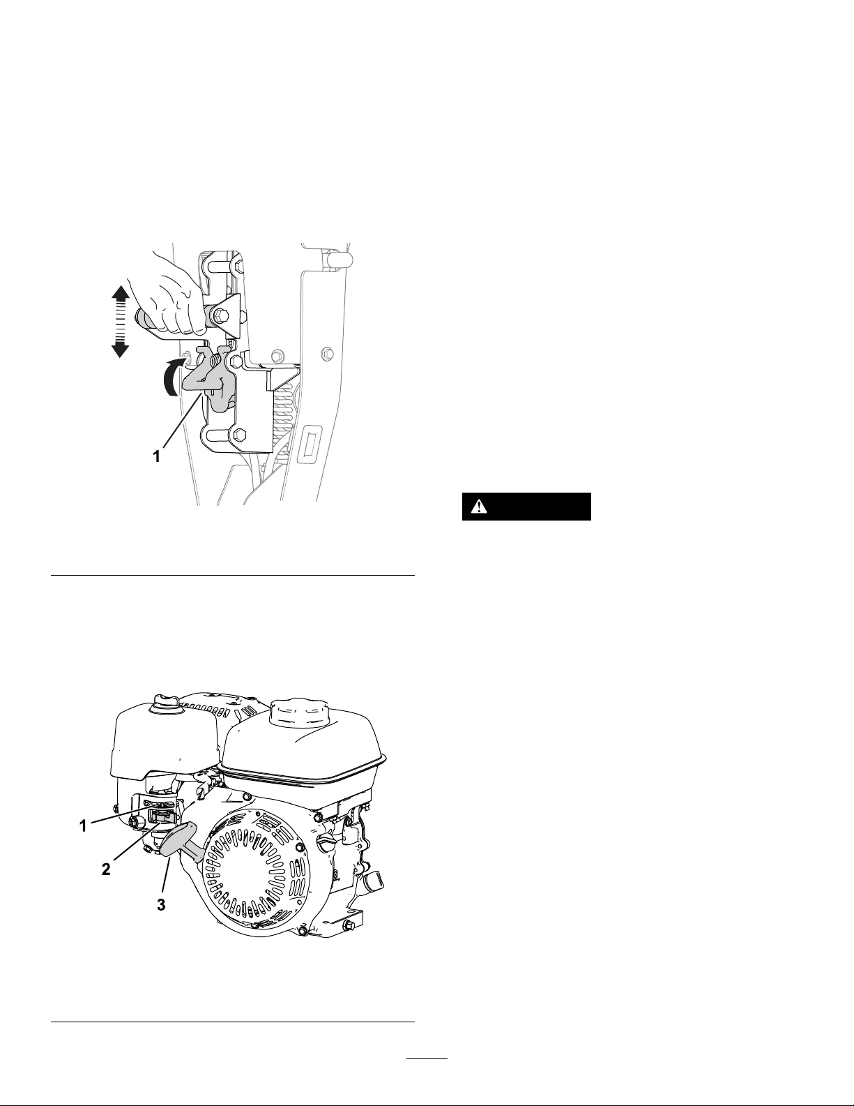
Handle-HeightAdjuster
Usethehandle-heightadjuster(Figure8)tomovethe
handleheighttoacomfortableoperatingposition.Pull
upontheadjusterandusethelift-assisthandleto
raiseorlowerthehandleheight.
Thefuel-shut-offvalveislocatedonthesideofthe
enginebelowthechokecontrol(Figure9).
Note:Closethefuel-shutoffvalvewhenthemachine
isnotusedforafewdays,duringtransporttoand
fromthejobsite,orwhenthemachineisparked
insideabuilding;refertoOpeningandClosingthe
Fuel-ShutoffValve(page16).
Recoil-StarterHandle
Pulltherecoil-starterhandle(Figure9)tostartthe
engine.
Kickstand
Thekickstand(Figure10)ismountedtotherearof
themachine.Usethekickstandwhenyouinstallor
removethetransportwheelsorthecuttingunit.
•TRANSPORT-WHEEL-SERVICEposition:
Tousethekickstandtoinstallthetransportwheels,
putyourfootonthekickstandwhilepullingupand
backonthelift-assisthandle(Figure10).
Figure8
1.Handle-heightadjuster
ChokeLever
Thechokelever(Figure9)islocatedontheleftfront
oftheengine.Usethelevertoaidinstartingacold
engine;refertoUsingtheChokeLever(page15).
g271081
CAUTION
Themachineisheavyandcancauseback
strainifliftedimproperly.
Putyourfootpressuredownonthe
kickstandanduseonlythelift-assist
handletoraisethemachine.Attemptingto
raisethemachineontothekickstandany
otherwaycancauseinjury.
•CUTTING-UNIT-SERVICEposition:
Topreventthemachinefromtippingbackward
whenremovingthecuttingunit,lowerthekickstand
andinsertapinorboltthroughthechassisholeon
therightsideofthemachine(Figure11).
1.Chokelever
2.Fuel-shutoffvalve
g265059
Figure9
3.Recoil-starterhandle
10
Page 11
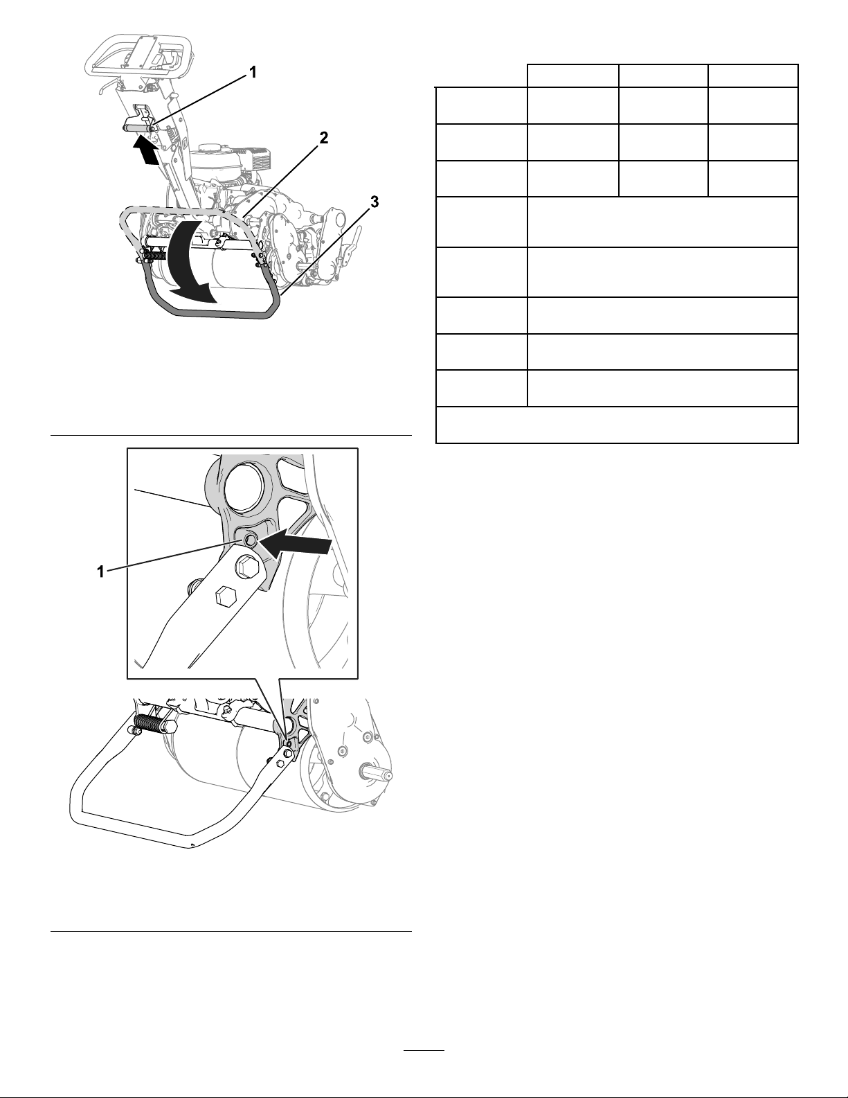
1.Lift-assisthandle
2.Kickstand—STORAGE
position
Figure10
3.Kickstand—TRANSPORT-WHEEL
SERVICEposition
Specications
Model04820Model04830Model04840
Width
Dryweight*95kg(210lb)
Widthofcut
Heightofcut
Clip
Engine
g273507
speed
Mowing
speed
Transport
speed
*Tractionunitonly.RefertothecuttingunitOperator’s
Manualfortheweightofeachcuttingunit.
84cm(33
inches)
46cm(18
inches)
Dependentontraction-drumposition[referto
AdjustingtheTraction-DrumPosition(page
14)]anduseofHighHeight-of-CutKit.
Dependentonreelspeedandreel-drive-pulley
position;refertoAdjustingtheClip
Lowidle:1,900±100rpm;Highidle:
3.2km/h(2mph)to5.6km/h(3.5mph)
91cm(36
inches)
100kg(220
lb)
53cm(21
inches)
Rate(page13).
3,450±100rpm
8.5km/h(5.3mph)
104cm(41
inches)
107kg(235
lb)
66cm(26
inches)
Figure11
Attachments/Accessories
AselectionofT oroapprovedattachmentsand
accessoriesisavailableforusewiththemachine
toenhanceandexpanditscapabilities.Contact
yourAuthorizedServiceDealerorauthorizedT oro
distributororgotowww.Toro.comforalistofall
approvedattachmentsandaccessories.
Toensureoptimumperformanceandcontinuedsafety
certicationofthemachine,useonlygenuineT oro
replacementpartsandaccessories.Replacement
partsandaccessoriesmadebyothermanufacturers
couldbedangerous,andsuchusecouldvoidthe
productwarranty.
g278594
1.Chassishole2.Kickstand—CUTTING-UNIT
SERVICEposition
11
Page 12

Operation
containersontheground,awayfromthevehicle
beforelling.
Note:Determinetheleftandrightsidesofthe
machinefromthenormaloperatingposition.
BeforeOperation
BeforeOperationSafety
GeneralSafety
•Neverallowchildrenoruntrainedpeopleto
operateorservicethemachine.Localregulations
mayrestricttheageoftheoperator.Theowner
isresponsiblefortrainingalloperatorsand
mechanics.
•Becomefamiliarwiththesafeoperationofthe
equipment,operatorcontrols,andsafetysigns.
•Shutofftheengine,removethekey(ifequipped),
andwaitforallmovementtostopbeforeyouleave
theoperator’sposition.Allowthemachinetocool
beforeadjusting,servicing,cleaning,orstoringit.
•Removeequipmentfromthetruckortrailerand
refuelitontheground.Ifthisisnotpossible,refuel
suchequipmentwithaportablecontainerrather
thanfromafuel-dispensernozzle.
•Keepthenozzleincontactwiththerimofthefuel
tankorcontaineroperatingatalltimesuntilfueling
iscomplete.
PerformingDaily
Maintenance
Performthedailymaintenanceprocedures;referto
DailyMaintenanceChecklist(page22).
CheckingtheEngine-Oil
Level
Checktheengine-oillevelbeforeeachuseorevery
8operatinghours,refertoCheckingtheEngine-Oil
Level(page23).
•Knowhowtostopthemachineandshutoffthe
machinequickly.
•Checkthatoperator-presencecontrols,safety
switches,andsafetyprotectivedevicesare
attachedandfunctioningproperly.Donotoperate
themachineunlesstheyarefunctioningproperly .
•Inspecttheareawhereyouwillusethemachine
andremoveallobjectsthatthemachinecould
throw.
FuelSafety
•Useextremecareinhandlingfuel.Itisammable
anditsvaporsareexplosive.
•Extinguishallcigarettes,cigars,pipes,andother
sourcesofignition.
•Useonlyanapprovedfuelcontainer.
•Donotremovethefuelcaporaddfueltothetank
whiletheengineisrunningorhot.
•Donotaddordrainfuelinanenclosedspace.
•Donotstorethemachineorfuelcontainerwhere
thereisanopename,spark,orpilotlight,such
asonawaterheaterorotherappliance.
•Ifyouspillfuel,donotattempttostarttheengine;
avoidcreatingasourceofignitionuntilthefuel
vaporshavedissipated.
FuelSpecications
Fueltankcapacity:2.0L(0.59USgallons)
Recommendedfuel:Unleadedgasolinewithan
octaneratingof87orhigher((R+M)/2ratingmethod)
Ethanol:Gasolinewithupto10%ethanol(gasohol)
or15%MTBE(methyltertiarybutylether)byvolume
isacceptable.EthanolandMTBEarenotthesame.
Gasolinewith15%ethanol(E15)byvolumeisnot
approvedforuse.
•Neverusegasolinethatcontainsmorethan
10%ethanolbyvolume,suchasE15(contains
15%ethanol),E20(contains20%ethanol),orE85
(containsupto85%ethanol).
•Donotusegasolinecontainingmethanol.
•Donotstorefueleitherinthefueltankorfuel
containersoverthewinterunlessyouuseafuel
stabilizer.
•Donotaddoiltogasoline.
•Forbestresults,useonlyclean,fresh(lessthan
30daysold)fuel.
•Usingunapprovedgasolinemaycause
performanceproblemsand/orenginedamage,
whichmaynotbecoveredunderthewarranty.
•Donotllcontainersinsideavehicleoronatruck
ortrailerbedwithaplasticliner.Alwaysplace
12
Page 13
FillingtheFuelTank
AdjustingtheClipRate
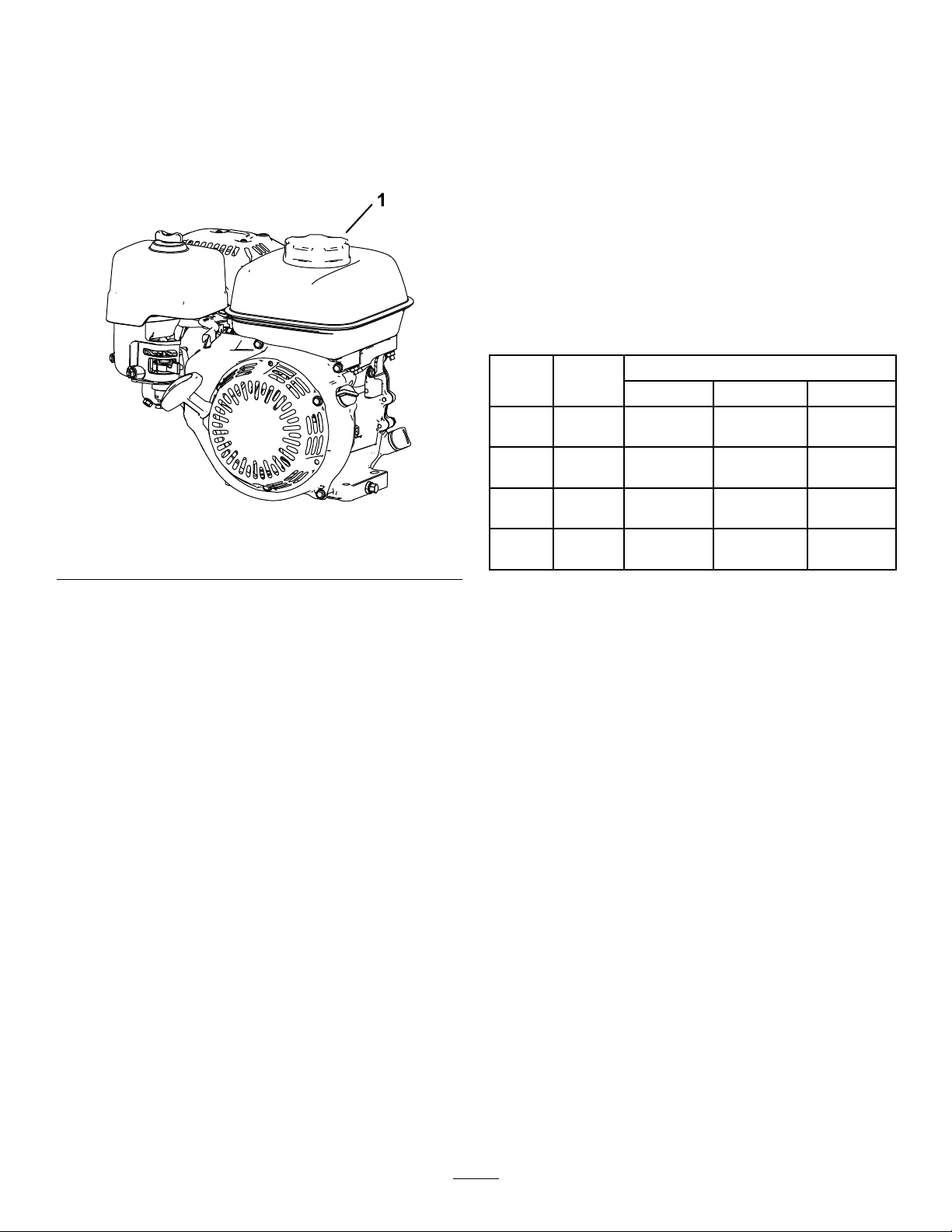
1.Cleanaroundthefuel-tankcapandremovethe
capfromthetank(Figure12).Fillthefueltank
tothebottomofthetank-neckopening;referto
yourengineOperator’sManual.
Important:Donotoverllthetankwithfuel.
Figure12
1.Fuel-tankcap
Thecliprateisdeterminedbythefollowingmachine
settings:
•Reelspeed:Youcanadjustthereelspeedtoa
highorlowsetting;refertoAdjustingtheReel
Speed(page13).
•Reel-drive-pulleyposition:Youcansetthe
reel-drivepulleysin2positions;refertoyour
cuttingunitOperator’sManual.
Todeterminethereelspeedandreel-drive-pulley
positionfortheappropriateclip,refertothefollowing
table:
ClipRate
Reel
Speed
LowLow7.3mm
LowHigh8.7mm
g265976
HighLow5.9mm
HighHigh5.0mm
Belt
Position
8-blade11-blade14-blade
(0.286inch)
(0.241inch)
(0.233inch)
(0.196inch)
CuttingUnit
(0.208inch)
(0.175inch)
(0.169inch)
(0.142inch)
5.3mm
4.4mm
4.3mm
3.6mm
4.2mm
(0.164inch)
3.5mm
(0.137inch)
3.4mm
(0.133inch)
2.8mm
(0.112inch)
2.Installthefuel-tankcapandwipeupanyspilled
fuel.
AdjustingtheReelSpeed
Usethereel-speed-controlknob(Figure13)toadjust
thereelspeed.
•Highreelspeed:Rotatetheknobsothatthe“H”
ontheknobisdirectedtowardthefrontofthe
machine.
•Lowreelspeed:Rotatetheknobsothatthe“L”
ontheknobisdirectedtowardthefrontofthe
machine.
13
Page 14
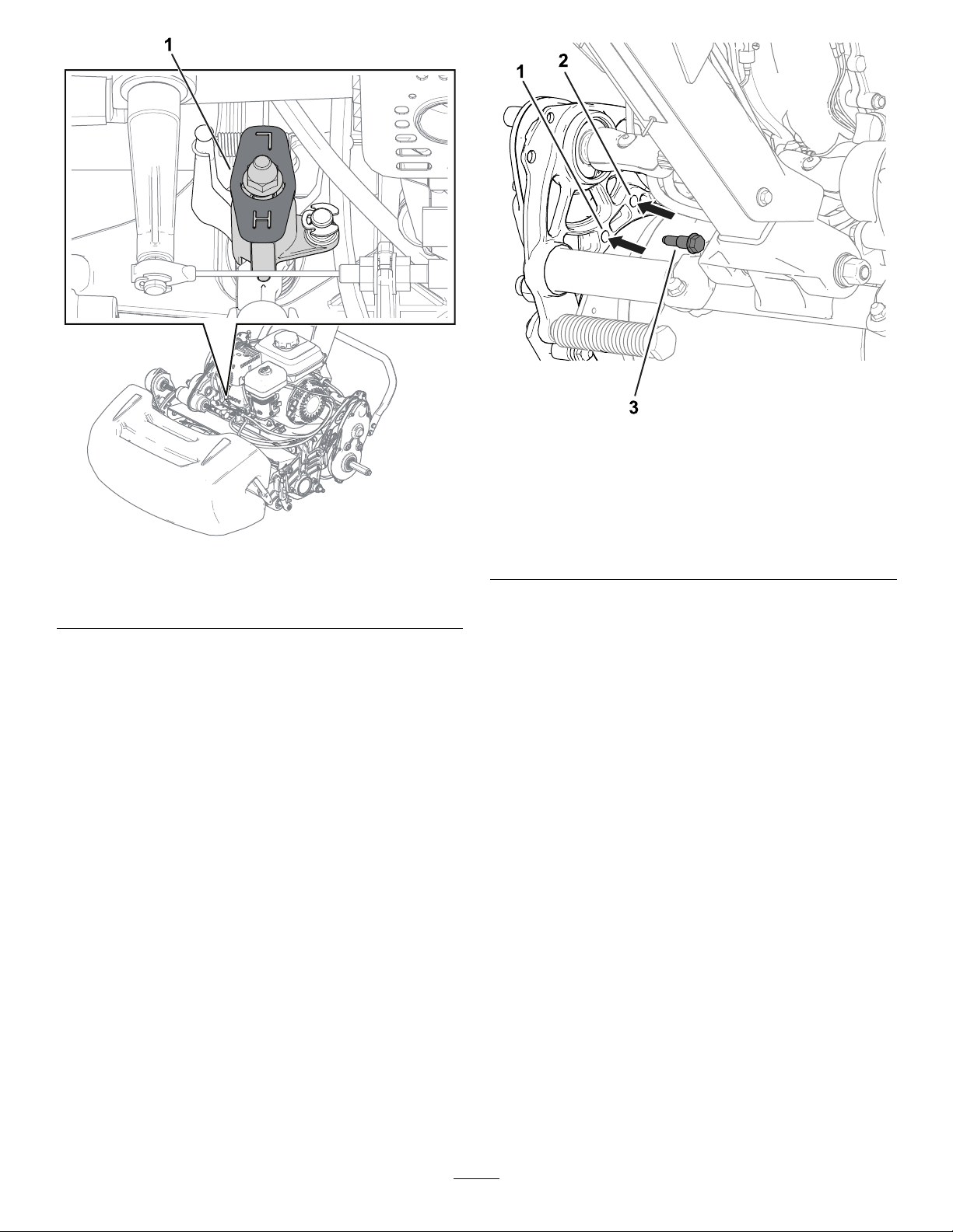
Figure14
Leftsideofthemachineshown
g277026
Figure13
1.Reel-speed-controlknob(showninthehigh-reel-speed
position)
Adjustingthe
Traction-DrumPosition
Thetractiondrumcanbeadjustedto2positions:
•LOWposition:Usethispositionformowingata
lowerheightofcut(e.g.,mowingagolf-course
green).
•HIGHposition:Usethispositionformowingata
higherheightofcut(e.g.,mowingagolf-course
teebox).
1.MovethekickstandtotheCUTTING-UNITSERVICE
position;refertoKickstand(page10).
2.Removetheshoulderbolts(Figure14)oneach
sideofthemachinethatsecurethedrumdrive
housingtothechassis.
1.Insertshoulderbolthere
fortheLOWposition.
g275053
2.Insertshoulderbolthere
fortheHIGHposition.
3.Aligntheholesinthechassiswiththeholesin
thedrivehousing.
4.Usethepreviouslyremovedshoulderboltsto
securethedrivehousingtothechassis(Figure
14).
5.MovethekickstandtotheSTORAGEposition;
refertoKickstand(page10).
3.Shoulderbolt
AdjustingtheHandle
Height
Usethehandle-heightadjustertoadjustthehandle
heighttoacomfortableoperatingposition;referto
Handle-HeightAdjuster(page10).
TransportingtheMachine
toaJobSite
TransportingtheMachineUsing
TransportWheels
Usethetransportwheelstotransportthemachinea
shorterdistance.
1.Installthetransportwheels;refertoInstalling
theTransportWheels(page19).
14
Page 15
2.Ensurethatthetractionandreel-drivecontrols
areintheNEUTRALposition.
3.Starttheengine;refertoStartingtheEngine
(page17).
4.SetthethrottlecontroltoSLOW,tipthefrontof
themachineup,graduallyengagethetraction
drive,andslowlyincreasetheenginespeed.
5.Adjustthethrottletooperatethemoweratthe
desiredgroundspeedandtransportthemachine
tothedesireddestination.
TransportingtheMachineUsinga
Trailer
Useatrailertotransportthemachineaconsiderable
distance.Usecautionwhileloadingandunloadingthe
machineontothetrailer.
1.Carefullydrivethemachineontothetrailer.
g274946
Figure15
2.Shutofftheengine,engagetheparkingbrake,
andturnthefuelvalvetotheOFFposition.
3.Useafull-widthrampforloadingthemachine
intoatrailerortruck.
4.Securelyfastenthemachinetothetrailer.
Note:Y oucanusetheT oroTransProtrailerto
transportthemachine.Forinstructionsonloadingthe
trailer,refertoyourtrailerOperator’sManual.
Important:Donotruntheenginewhile
transportingitonatrailerbecausedamagecan
occurtothemachine.
RemovingtheTransport
Wheels
1.Releasetheclutchbail,usethethrottlecontrolto
lowertheenginespeed,andshutofftheengine.
2.Movethekickstandtothe
TRANSPORT-WHEEL-SERVICEposition;referto
Kickstand(page10).
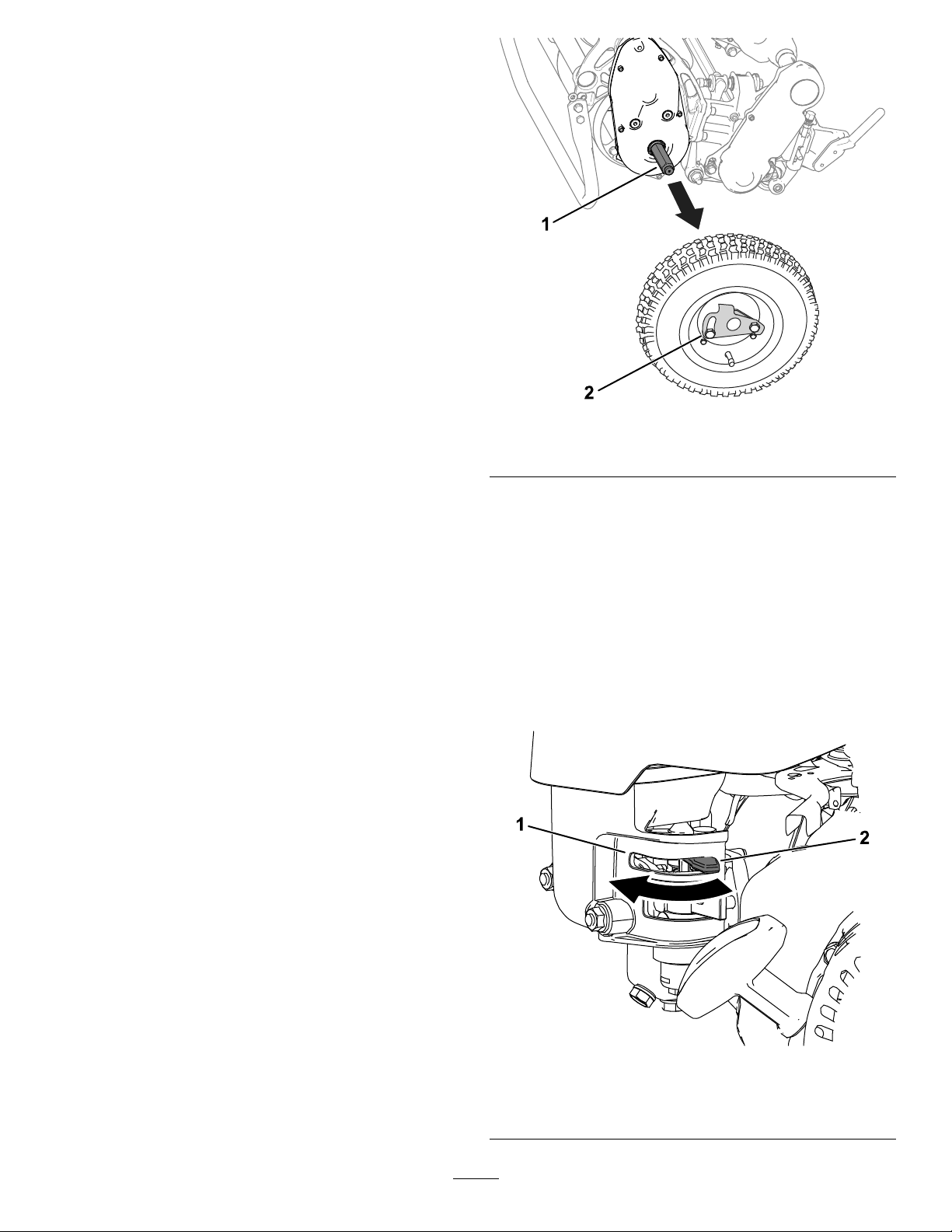
1.Axle2.Wheel-lockingclip
4.Carefullylowerthemachineoffofthekickstand
bypushingforwardslowlyorbyliftingthelower
handlesupport,allowingthekickstandtospring
backtotheSTORAGEposition;refertoKickstand
(page10).
UsingtheChokeLever
Usethechokelevertoaidinstartingacoldengine.
MovethelevertotheCHOKEpositionwhenstartinga
coldengine.Aftertheenginestarts,movethelever
totheRUNposition.
3.Removethetransportwheelsbypushingthe
wheel-lockingclipsoutoftheaxles(Figure15).
1.Chokelever—CHOKE
15
g273508
Figure16
position
2.Chokelever—RUN
position
Page 16
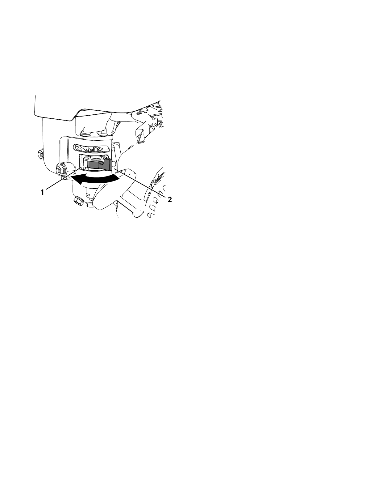
OpeningandClosingthe
Fuel-ShutoffValve
Controlfuelowtotheenginewiththefuel-shutoff
valveasfollows:
•T oopenthefuelvalve,turnthefuel-shutofflever
towardtherecoilstarterhandle(Figure17).
•T oshutthefuelvalve,turnthefuel-shutofflever
awayfromtherecoilstarterhandle(Figure17).
Figure17
1.Fuel-shutoff
lever—CLOSEDposition
2.Fuel-shutofflever—OPEN
position
DuringOperation
DuringOperationSafety
GeneralSafety
•Theowner/operatorcanpreventandisresponsible
foraccidentsthatmaycausepersonalinjuryor
propertydamage.
•Wearappropriateclothing,includingeye
protection;longpants;substantial,slip-resistant
footwear;andhearingprotection.Tiebacklong
hairanddonotwearlooseclothingorloose
jewelry.
•Donotoperatethemachinewhileill,tired,or
undertheinuenceofalcoholordrugs.
•Useyourfullattentionwhileoperatingthe
machine.Donotengageinanyactivitythat
causesdistractions;otherwise,injuryorproperty
damagemayoccur.
•Beforeyoustartthemachine,ensurethatalldrives
areinneutral,theparkingbrakeisengaged,and
youareintheoperatingposition.
•Keepbystandersandchildrenoutoftheoperating
area.Ifco-workersmustbepresent,usecaution
andensurethatthegrassbasketisinstalledon
themachine.
•Operatethemachineonlyingoodvisibilitytoavoid
holesorhiddenhazards.
•Donotoperatethemachinewhenthereistherisk
oflightning.
•Avoidmowingonwetgrass.Poorfootingcould
causeaslip-and-fallaccident.
•Keepyourhandsandfeetawayfromthecutting
unit.
•Lookbehindanddownbeforebackinguptobe
sureofaclearpath.
•Usecarewhenapproachingblindcorners,shrubs,
trees,orotherobjectsthatmayobscureyour
vision.
•Stopthecuttingunitwheneveryouarenotmowing.
•Disengagethedrivetothecuttingunitandshutoff
theenginebeforeadjustingtheheightofcut.
•Neverrunanengineinanareawhereexhaust
gassesareenclosed.
•Neverleavearunningmachineunattended.
g273576
•Beforeyouleavetheoperator’sposition,dothe
following:
–Parkthemachineonalevelsurface.
–Disengagethecuttingunit.
–Engagetheparkingbrake.
–Shutoffthemachineandremovethekey(if
equipped).
–Waitforallmovementtostop.
•Shutoffthemachinebeforeemptyingthebasket.
•Donottouchtheengine,mufer,orexhaustpipe
whiletheengineisrunningorsoonafterithas
shutoffbecausetheseareascouldbehotenough
tocauseburns.
•Shutoffthemachineanddisengagethedriveto
thecuttingunitinthefollowingsituations:
–Beforefueling
–Beforeclearingblockages
–Beforeremovingthegrassbasket
–Beforechecking,cleaning,ormaintainingthe
cuttingunit
–Afterstrikingaforeignobjectorifanabnormal
vibrationoccurs.Inspectthecuttingunitfor
damageandmakerepairsbeforestartingand
operatingthemachine
–Beforeleavingtheoperatingposition
•Useonlyaccessoriesandattachmentsapproved
byTheT oro®Company.
16
Page 17

SlopeSafety
•Slopesareamajorfactorrelatedtolossofcontrol
androlloveraccidents,whichcanresultinsevere
injuryordeath.Y ouareresponsibleforsafeslope
operation.Operatingthemachineonanyslope
requiresextracaution.Beforeusingthemachine
onaslope,dothefollowing:
–Reviewandunderstandtheslopeinstructions
inthemanualandonthemachine.
–Evaluatethesiteconditionsofthedayto
determineiftheslopeissafeformachine
operation.Usecommonsenseandgood
judgmentwhenperformingthisevaluation.
Changesintheterrain,suchasmoisture,can
quicklyaffecttheoperationofthemachineon
aslope.
•Operateacrossslopes,neverupanddown.Avoid
operationonexcessivelysteeporwetslopes.
Poorfootingcouldcauseaslip-and-fallaccident.
•Identifyhazardsatthebaseoftheslope.Do
notoperatethemachineneardrop-offs,ditches,
embankments,water,orotherhazards.The
machinecouldsuddenlyrolloverifawheelgoes
overtheedgeortheedgecollapses.Keepasafe
distancebetweenthemachineandanyhazard.
Useahandheldtooltooperateintheseareas.
1.Ensurethatthetraction-driveleverisinthe
neutralposition.
2.Ensurethatthefuel-shutoffvalveisopen;refer
toOpeningandClosingtheFuel-ShutoffValve
(page16)
3.MovetheOn/OffswitchtotheONposition.
4.Usethethrottlecontroltoincreasetheengine
speed.
5.Movethechokeleverhalfwaybetweenthe
CHOKEandRUNpositionswhenstartingacold
engine;refertoUsingtheChokeLever(page
15)
Note:Thechokemaynotberequiredwhen
startingawarmengine.
6.Pulltherecoil-starthandleoutuntilpositive
engagementresults,thenpullitvigorouslyto
starttheengine.
Important:Donotpulltherecoilropetoits
limitorletgoofthestarterhandlewhenthe
ropeispulledout;theropemaybreakorthe
recoilassemblymaybedamaged.
7.MovethechokelevertotheRUNpositionasthe
enginewarmsup.
•Avoidstarting,stopping,orturningthemachineon
slopes.Avoidmakingsuddenchangesinspeedor
direction;turnslowlyandgradually.
•Donotoperateamachineunderanyconditions
wheretraction,steeringorstabilityisinquestion.
Beawarethatoperatingthemachineonwet
grass,acrossslopesordownhillmaycausethe
machinetolosetraction.Lossoftractiontothe
drivewheelsmayresultinslidingandalossof
brakingandsteering.Themachinecanslideeven
ifthedrivewheelsarestopped.
•Removeormarkobstaclessuchasditches,holes,
ruts,bumps,rocks,orotherhiddenhazards.T all
grasscanhideobstacles.Uneventerraincould
overturnthemachine.
•Ifyoulosecontrolofthemachine,stepawayfrom
thedirectionoftravelofthemachine.
•Alwayskeepthemachineingearwhengoing
downslopes.Donotcoastdownhill(applicable
onlytogear-driveunits).
StartingtheEngine
Note:Forillustrationsanddescriptionsofthecontrols
referencedinthissection,refertoControls(page9).
Note:Ensurethatthespark-plugwireisinstalledon
thesparkplug.
17
Page 18
OperatingTips
Important:Grassclippingsactasalubricant
whenmowing.Operatingthecuttingunit
excessivelywithoutgrassclippingscandamage
thecuttingunit.
•Mowthegreensinastraightback-and-forth
directionacrossthegreen.
•Avoidcircularmowingorturningthemachineon
thegreensareastopreventscufng.
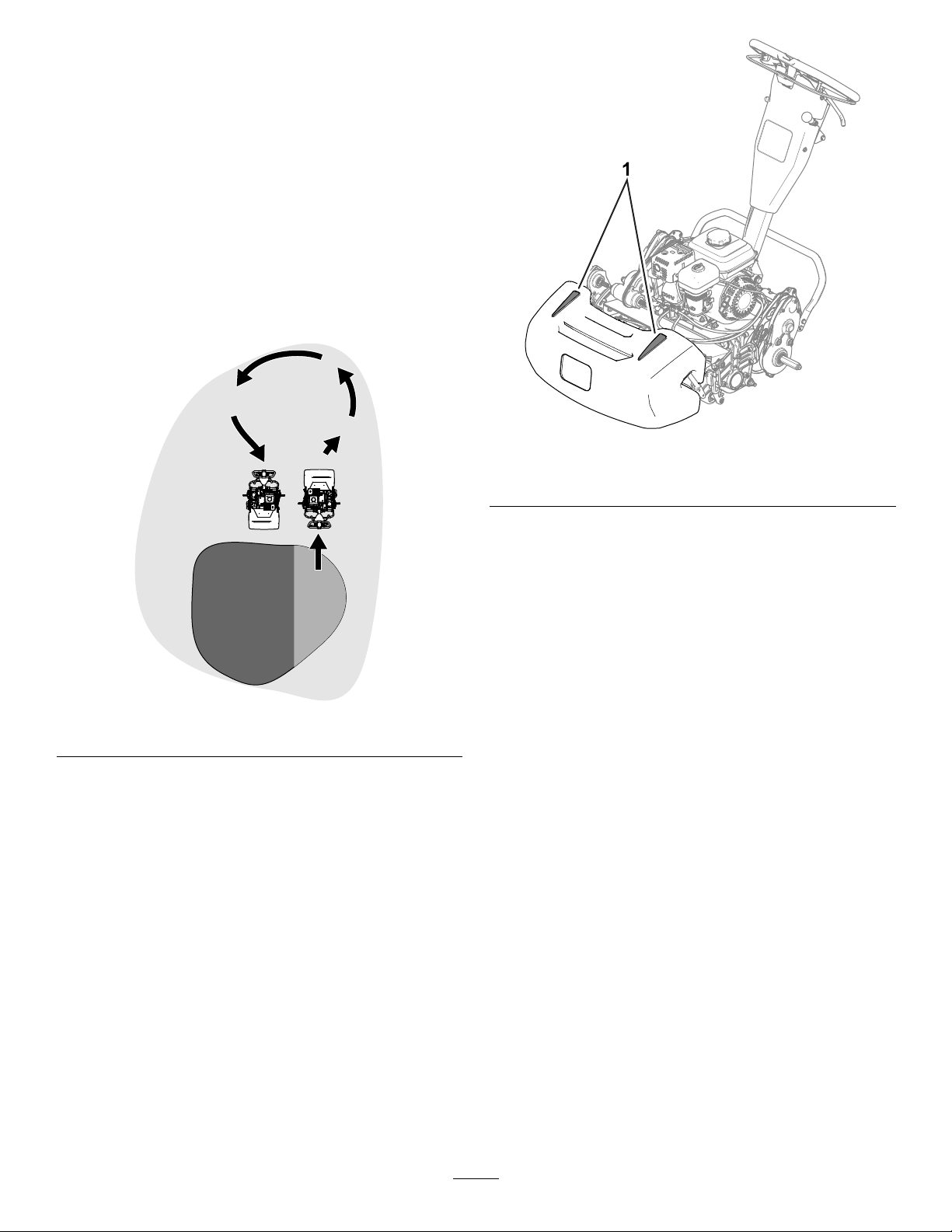
•Turnthemachineoffthegreenbyraisingthe
cuttingreel(pushingthehandledown)and
performingatear-shapedturnonthetractiondrum
(Figure18).
g272991
Figure19
1.Alignmentstripes
Figure18
•Mowatanormalwalkingpace.Fastspeedssaves
littletimeandresultsinaninferiormowingjob.
•T oassistinmaintainingastraightlineacross
thegreenandtokeepthemachineanequal
distancefromtheedgeofthepreviouscut,usethe
alignmentstripesonthebasket(Figure19).
OperatingtheMachineinLow
LightConditions
UsetheLEDLightKitwhenyouoperatethemachine
inlowlightconditions.ContactyourauthorizedToro
distributorforthiskit.
Important:Donotuseotherlightsystemswith
g271799
thismachine,astheywillnotoperateproperly
withtheengineACoutput.
OperatingtheControlswhile
Mowing
1.Starttheengine,setthethrottletoareduced
speed,pushdownonthehandletoraisethe
cuttingunit,andengagethetractiondriveto
transportthemachineontothecollarofthe
green.
2.Stopthemachineonthegreen.
3.Usethecutting-unit-drivelevertoengagethe
cuttingunit,increasethethrottlespeeduntil
themachineistravelingatthedesiredground
speed,engagethetractiondrivetomovethe
machineontothegreen,lowerthecuttingunitto
theground,andbeginmowing.
18
Page 19
ShuttingOfftheEngine
InstallingtheTransport
1.Releasetheclutchbail.
2.MovethethrottlecontroltotheSLOWposition.
3.MovetheOn/OffswitchtotheOFFposition.
4.Closethefuel-shutoffvalvebeforeyoustoreor
transportthemachine
AfterOperation
AfterOperationSafety
GeneralSafety
•Shutofftheengine,removethekey(ifequipped),
andwaitforallmovementtostopbeforeyouleave
theoperator’sposition.Allowthemachinetocool
beforeadjusting,servicing,cleaning,orstoringit.
•Cleangrassanddebrisfromthemachinetohelp
preventres.Cleanupoilorfuelspills.
•Allowthemachinetocoolbeforestoringthe
machineinanyenclosure.
•Donotstorethemachineorfuelcontainerwhere
thereisanopename,spark,orpilotlight,such
asonawaterheateroronotherappliances.
Wheels
1.Movethekickstandtothe
TRANSPORT-WHEEL-SERVICEposition;referto
Kickstand(page10)
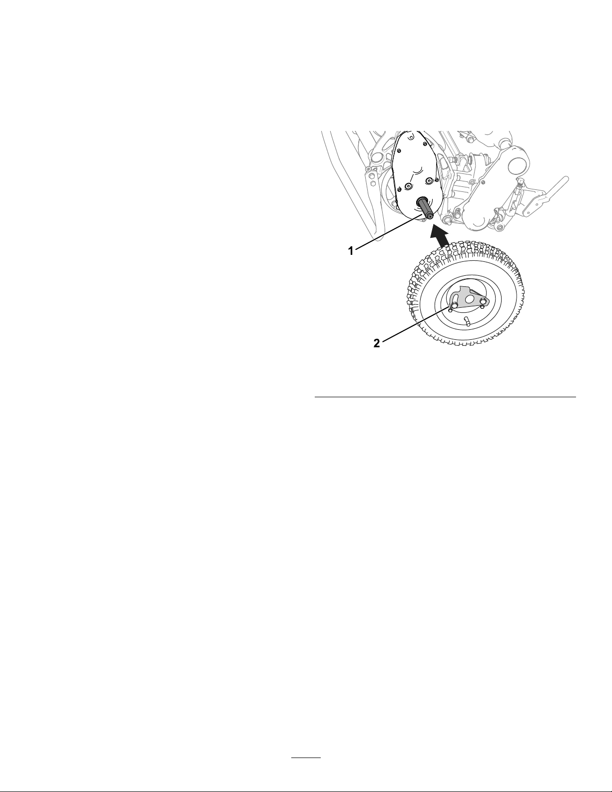
2.Slideawheelontoanaxle(Figure20).
g273510
Figure20
1.Axle2.Wheel-lockingclip
•Reducethethrottlesettingbeforeshuttingoff
theengineandturnoffthefuel-shutoffvalve(if
equipped)aftermowing.
OperatingtheControls
afterMowing
1.Drivethemachineoffofthegreen,pushdown
onthehandletoraisethecuttingunit,release
theclutchbail,disengagethecuttingunit,and
shutofftheengine.
2.Removethegrassbasketandemptythebasket
ofclippings.
3.Installthegrassbasketonthemachineand
transportthemachinetostorage.
TransportingtheMachine
Aftermowing,transportthemachineawayfromthe
jobsite;refertoTransportingtheMachineUsing
TransportWheels(page14)orTransportingthe
MachineUsingaTrailer(page15).
3.Pivotthewheel-lockingclip(Figure20)away
fromcenterofthewheel,allowingittoslide
fartherontotheaxle.
4.Rotatethewheelbackandforthuntilitslides
completelyontotheaxleandthelockingclipis
securedinthegrooveontheaxleshaft.
5.Repeattheprocedureontheoppositesideof
themachine.
6.Carefullylowerthemachineoffthekickstand.
19
Page 20
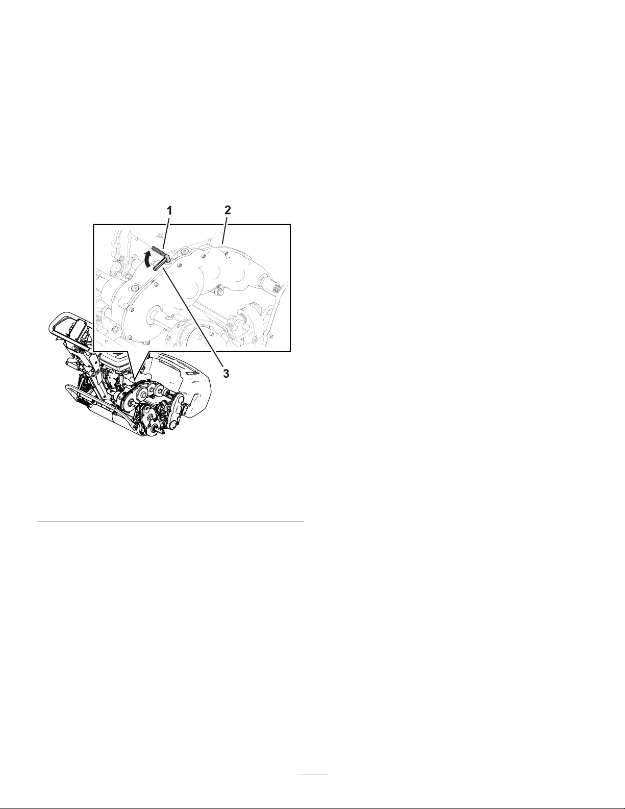
EngagingorDisengaging
theTransmission
Youcandisengagethedrumfromthetransmission
toallowthemachinetobemaneuvered.Disengage
thetransmissionwhenyouneedtomovethe
machinewithoutstartingtheengine(e.g.,performing
maintenanceinanenclosedarea).
Beforeyouoperatethemachine,ensurethatyou
engagethetransmission.
1.Locatethetraction-engagementleveronthe
transmissiongearbox(Figure18).
Figure21
1.Traction-engagement
lever—DISENGAGED
position
2.Transmissiongearbox
2.Performthefollowingsteptoengageor
disengagethetransmission:
3.Traction-engagement
lever—ENGAGEDposition
•Disengagethetransmission:Rotatethe
levertotheDISENGAGEDposition.
•Engagethetransmission:Rotatethelever
totheENGAGEDposition.
g272196
20
Page 21

Maintenance
WARNING
Failuretoproperlymaintainthemachinecouldresultinprematurefailureofmachinesystems
causingpossibleharmtoyouorbystanders.
Keepthemachinewellmaintainedandingoodworkingorderasindicatedintheseinstructions.
Note:Determinetheleftandrightsidesofthemachinefromthenormaloperatingposition.
Important:Donottipthemachineatananglegreaterthan25°.Tippingthemachinebeyond25°leads
tooilleakingintothecombustionchamberand/orfuelleakingoutofthefuel-tankcap.
Important:Refertoyourengineowner’smanualforadditionalmaintenanceprocedures.
MaintenanceSafety
•Beforeyouleavetheoperator’sposition,dothe
following:
–Parkthemachineonalevelsurface.
–Movethethrottletothelow-idleposition.
–Disengagethecuttingunit(s).
–Ensurethatthetractionisinneutral.
–Engagetheparkingbrake.
–Shutoffthemachineandremovethekey(if
equipped).
–Waitforallmovementtostop.
•Allowmachinecomponentstocoolbefore
performingmaintenance.
•Ifpossible,donotperformmaintenancewhilethe
machineisrunning.Keepawayfrommovingparts.
•Iftheenginemustberunningtoperforma
maintenanceadjustment,keepyourhands,feet,
RecommendedMaintenanceSchedule(s)
clothing,andanypartsofthebodyawayfromthe
cuttingunit,attachments,andanymovingparts.
Keepbystandersaway.
•Cleangrassanddebrisfromthecuttingunit,drive,
mufer,coolingscreen,andtheenginetohelp
preventres.Cleanupoilorfuelspills.
•Keepallpartsingoodworkingcondition.Replace
allworn,damaged,ormissingpartsanddecals.
Keepallhardwaretighttoensurethatthemachine
isinsafeworkingcondition.
•Checkthegrasscatchercomponentsfrequently
andreplacethemwhennecessary.
•T oensuresafe,optimalperformanceofthe
machine,useonlygenuineT ororeplacement
parts.Replacementpartsmadebyother
manufacturerscouldbedangerous,andsuchuse
couldvoidtheproductwarranty .
•Ifmajorrepairsareeverneededorifassistanceis
desired,contactanauthorizedT orodistributor.
MaintenanceService
Interval
Aftertherst20hours
Beforeeachuseordaily
Every50hours
Every100hours
Every300hours
MaintenanceProcedure
•Changetheengineoil.
•Tightenthehandle-isolationhardware.
•Checktheengine-oillevel.
•Inspecttheair-lterelements.
•Cleantheair-lterelements.
•Changetheengineoil.
•Inspectandadjustthesparkplug;replaceitifnecessary .
•Replacethepaperlterelement(Morefrequentlyindustyoperatingconditions).
•Replacethesparkplug.
21
Page 22

DailyMaintenanceChecklist
Important:Duplicatethispageforroutineuse.
Maintenance
CheckItem
Checkthe
brake-lock-lever
operation.
Checkthefuel
level.
Checkthe
engine-oillevel.
Checktheair
lter.
Cleantheengine
coolingns.
Checkfor
unusualengine
noises.
Checkfor
unusual
operatingnoises.
Checkthe
reel-to-bedknife
adjustment.
Checkthe
height-of-cut
adjustment.
Touchup
damagedpaint.
Cleanthe
machine.
Fortheweekof:
Mon.Tues.Wed.Thurs.Fri.
Sat.Sun.
NotationforAreasofConcern
Inspectionperformedby:
ItemDate
Information
22
Page 23
Pre-Maintenance
EngineMaintenance
Procedures
EngineSafety
PreparingtheMachinefor
Maintenance
WARNING
Whileyouaremaintainingoradjustingthe
machine,someonecouldstarttheengine.
Accidentallystartingtheenginecould
seriouslyinjureyouorotherbystanders.
Releasetheclutchbail,engagetheparking
brake,andpullthewireoffthesparkplug
beforeyoudoanymaintenance.Alsopush
thewireasidesoitdoesnotaccidentally
contactthesparkplug.
Performthefollowingbeforeservicing,cleaning,or
makinganyadjustmentstothemachine.
1.Parkthemachineonalevelsurface.
2.Shutofftheengine.
3.Engagetheparkingbrake.
•Donotchangethegovernorspeedoroverspeed
theengine.
•Runtheenginedryorremovethefuelwithahand
pump;neversiphonthefuel.Ifyoumustdrainthe
fueltank,doitoutdoors.
ServicingtheEngineOil
Fillthecrankcasewithapproximately0.56L(19
oz)oftheproperviscosityoilbeforestarting.The
engineusesahigh-qualityoilthathastheAmerican
PetroleumInstitute(API)serviceclassicationofSJor
higher.Selecttheproperoilviscosity(weight)based
ontheambienttemperature.Figure23illustratesthe
temperature/viscosityrecommendations.
4.Waitforallmovingpartstostopandallowthe
enginetocoolbeforeservicing,storing,or
makingrepairs.
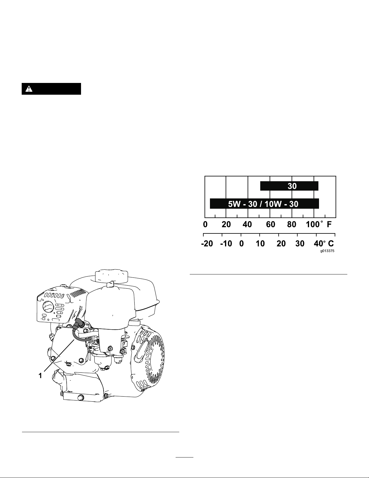
5.Disconnectthespark-plugwire(Figure22).
Figure22
1.Spark-plugwire
g013375
Figure23
Note:Multi-gradeoils(5W-20,10W-30and10W-40)
increaseoilconsumption.Checktheengine-oillevel
morefrequentlywhenyouusetheseoils.
CheckingtheEngine-OilLevel
ServiceInterval:Beforeeachuseordaily
Theidealtimetochecktheengine-oilleveliswhenthe
engineiscoolorbeforeyouhavestartedtheengine
fortheday.Ifyouhavealreadyrantheengine,allow
theoiltodrainbackdowntothesumpforatleast10
minutesbeforeyouchecktheengine-oillevel.
1.Shutofftheengineandwaitforallmovingparts
tostop;refertoShuttingOfftheEngine(page
19).
g265998
2.Positionthemachinesothattheengineislevel,
andcleantheareaaroundtheoil-lltube(Figure
24).
23
Page 24
ChangingtheEngineOil
ServiceInterval:Aftertherst20hours/Aftertherst
month(whichevercomesrst)
Every100hours/Every6months(whichever
comesrst)
WARNING
Oilmaybehotaftertheenginehasbeenrun,
andcontactwithhotoilcancausesevere
personalinjury.
Avoidcontactingthehotengineoilwhenyou
drainit.
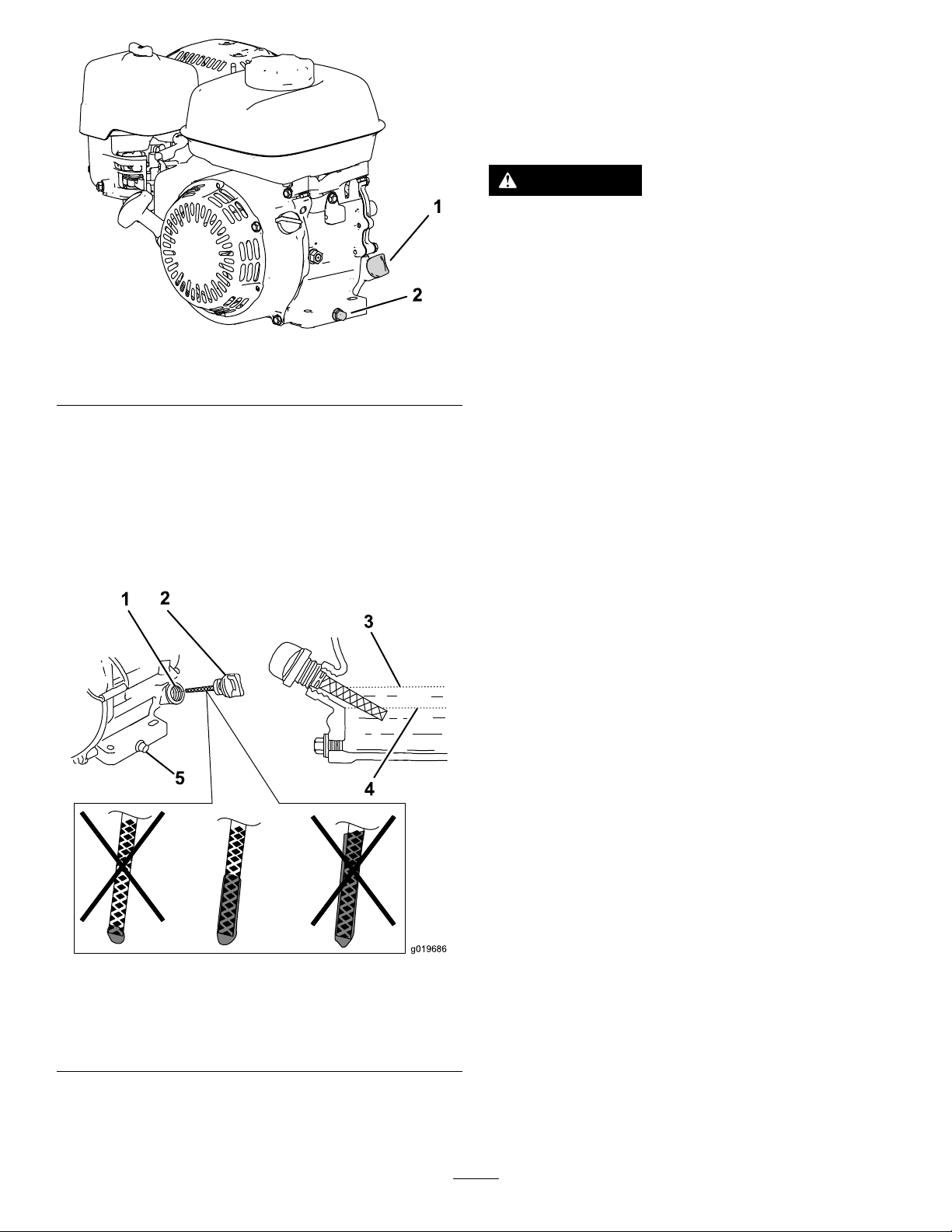
Figure24
1.Dipstick2.Drainplugandwasher
3.Removethedipstickbyrotatingit
counterclockwise.
4.Removethedipstickandwipetheendclean.
5.Insertthedipstickfullyintotheoil-lltube,but
donotthreaditin.
6.Removethedipstickandchecktheengine-oil
level(Figure25).
g266053
1.Shutofftheengineandwaitforallmovingparts
tostop;refertoShuttingOfftheEngine(page
19).
2.Placeapanunderthedrainplugtocatchtheoil.
3.Removethedrainplug,washer,anddipstick
(Figure24).
4.Positiontheenginesothattheoildrainsfrom
theengine.
5.Whentheoilhasdrainedcompletely,movethe
enginetoalevelpositionandinstallthedrain
plugandanewwasher.
Note:Disposeoftheusedoilatacertied
recyclingcenter.
6.Slowlypouroilintotheoil-llholeuntiltheoil
isatthecorrectlevel.
7.Ensurethattheoilisatthecorrectlevelonthe
dipstick;refertoCheckingtheEngine-OilLevel
(page23).
8.Threadthedipstickintotheoil-llhole.
9.Wipeupanyspilledoil.
10.Connectthewiretothesparkplug.
Figure25
1.Fillertube4.Lowerlimit
2.Dipstick5.Drainplug
3.Upperlimit
7.Iftheengine-oillevelisincorrect,addordrainoil
tocorrectthelevel;refertoChangingtheEngine
Oil(page24).
ServicingtheAirCleaner
ServiceInterval:Beforeeachuseordaily
Every50hours/Every3months(whichever
comesrst)
Every300hours/Yearly(whichevercomesrst)
g019686
Important:Donotoperatetheenginewithout
theairlterassembly;extremeenginedamage
willoccur.
1.Shutofftheengineandwaitforallmovingparts
tostop;refertoShuttingOfftheEngine(page
19).
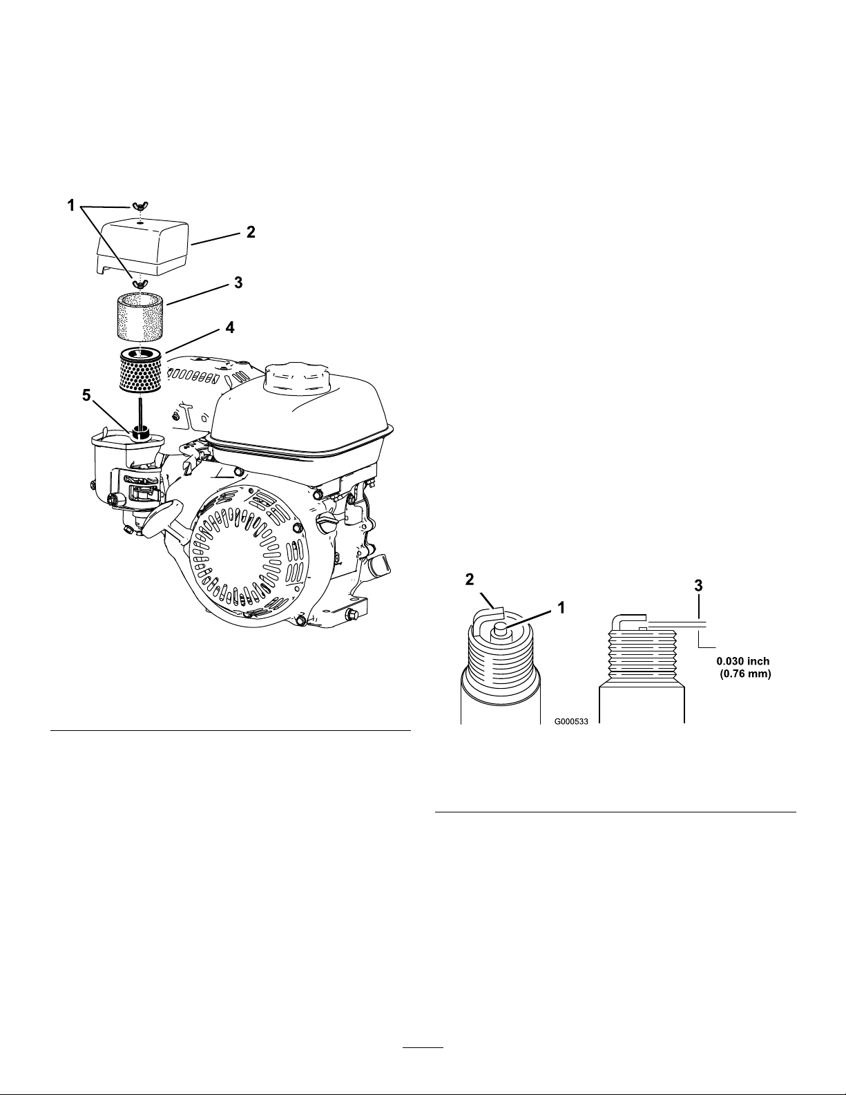
2.Removethewingnutsecuringtheair-cleaner
cover(Figure26).
3.Removetheair-cleanercover.
24
Page 25
Note:Ensurethatnodirtordebrisfromthe
air-cleanercoverfallintothebase.
Note:Ensurethatdirtanddebrisdonotenter
theairductleadingtothecarburetor.
4.Removethefoamandpaperelementsfromthe
base.
5.Removethefoamelementfromthepaper
element.
6.Inspectthefoamandpaperelements;replace
themiftheyaredamagedorexcessivelydirty.
11.Installtheair-cleanerelementsandensurethat
theyareproperlypositioned.Installthelower
wingnut.
12.Installthecoverandinstalltheupperwingnut
tosecureit.
ServicingtheSparkPlug
ServiceInterval:Every100hours/Every6months
(whichevercomesrst)
Every300hours/Yearly(whichevercomesrst)
UseanNGKBPR6ESsparkplugorequivalent.
1.Shutofftheengineandwaitforallmovingparts
tostop;refertoShuttingOfftheEngine(page
19).
2.Cleanaroundthesparkplug.
3.Removethesparkplugfromthecylinderhead.
Important:Replaceacracked,fouled,or
dirtysparkplug.Donotsandblast,scrape,
orcleantheelectrodesbecauseengine
damagecouldresultfromgritenteringthe
cylinder.
Figure26
1.Wingnut
2.Air-cleanercover
3.Foamelement
4.Paperlterelement
5.Gasketandairduct
7.Cleanthepaperelementbytappingitgentlyto
removethedirt.
Note:Donottrytobrushdirtoffthepaper
element;brushingforcesthedirtintothebers.
Replacetheelementiftappingitfailstoremove
thedirt.
8.Cleanthefoamelementinwarm,soapywater
orinanonammablesolvent.
Note:Donotusegasolinetocleanthefoam
elementbecauseitcouldcreateariskofreor
explosion.
9.Rinseanddrythefoamelementthoroughly .
10.Wipedirtfromthebaseandthecoverwitha
moistrag.
4.Setthegapontheplugto0.7to0.8mm(0.028
to0.031inch)
g265999
g000533
Figure27
1.Center-electrodeinsulator
2.Sideelectrode
3.Airgap
5.Carefullyinstallthesparkplugbyhand(toavoid
crossthreading)untilitishandtight.
6.Tightenthesparkpluganadditional1/2turnif
itisnew;otherwise,tightenitanadditional1/8
to1/4turn.
Important:Aloosesparkplugcanbecome
veryhotandcandamagetheengine;
overtighteningasparkplugmaydamagethe
threadsinthecylinderhead.
7.Connectthewiretothesparkplug.
25
Page 26
ControlsSystem
Maintenance
AdjustingtheTraction
Cable
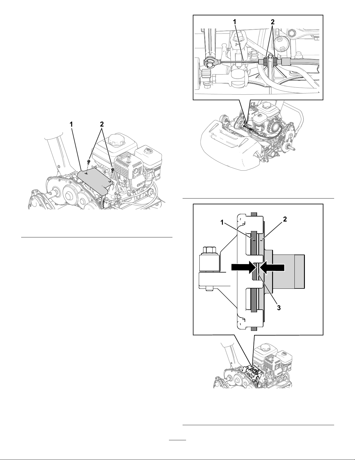
Adjustthetractioncabletoachieveagapof1.5mm
(0.06inch)betweenthefrictiondiscandthepressure
plate.
1.Accessthefrictiondiscandpressureplateby
removingtheclutchcover(Figure28).
g274532
Figure29
1.Tractioncable2.Jamnut
Figure28
1.Clutchcover
2.Loosenthejamnutsandadjustthetraction
cablesothata1.5mm(0.06inch)gapis
betweenthefrictiondiscandthepressureplate
(Figure29andFigure30).
2.Bolt
g274480
26
1.Frictiondisc
2.Pressureplate
g274479
Figure30
3.Gap—1.5mm(0.06inch)
Page 27
Adjustingthe
Service/ParkingBrake
Adjusttheservice/parkingbrakeifitslipsduring
operation.
1.Engagetheparkingbrake.
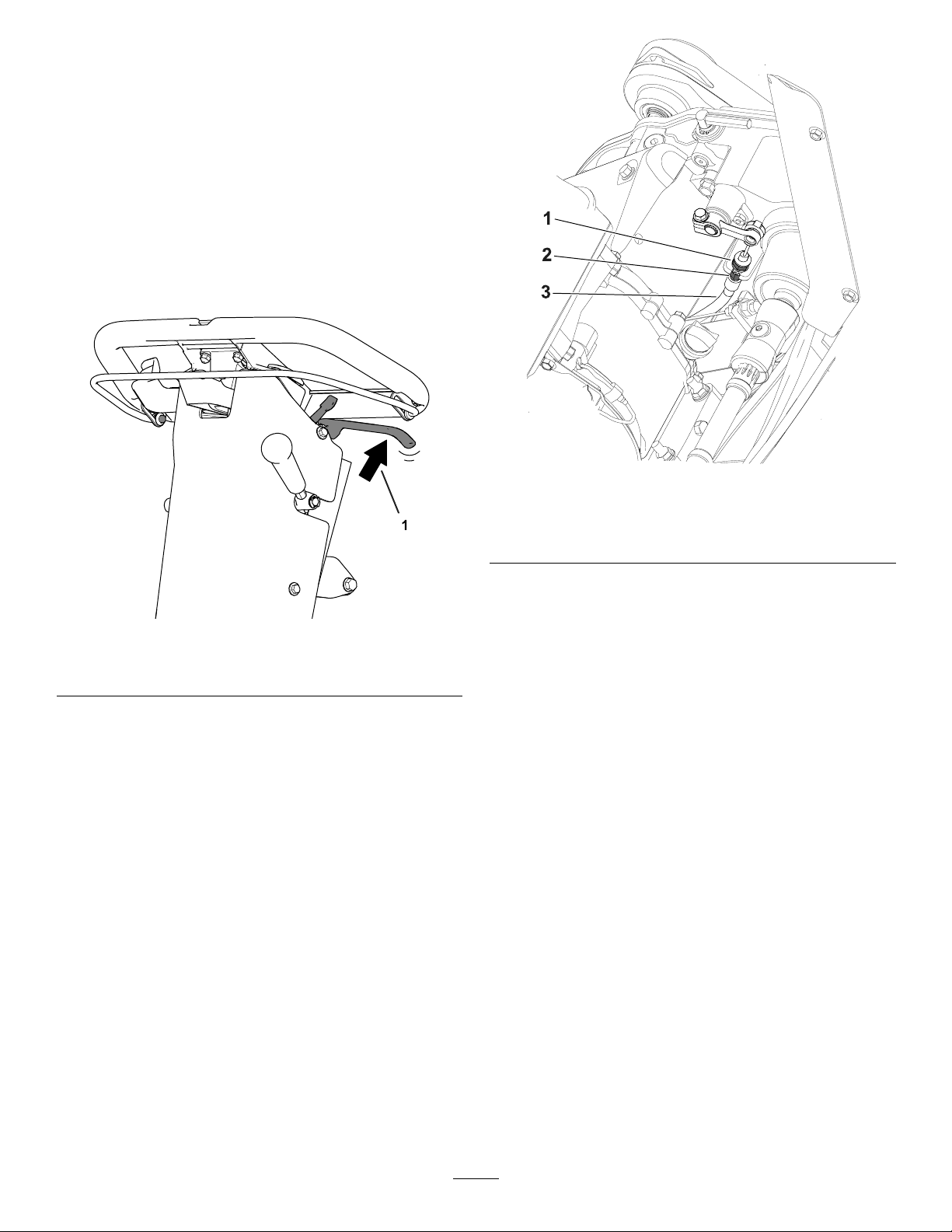
2.Usingaspringscale,applyaforceonthe
service-brakelever(Figure31).
Theparkingbrakeshouldreleasewhenyou
attainaforceof8to10kg(18to22lb).Ifthe
parkingbrakedoesnotreleasewithin8to10kg
(18to22lb)offorce,adjustthebrakecable.
g304662
Figure32
Figure31
1.Applyforcetoreleasetheparkingbrake.
3.Performthefollowingstepstoadjustthe
brake-cabletension:
•T oincreasethecabletension,loosenthe
front-cablejamnutandtightentherearjam
nut(Figure32).Repeatstep2andadjust
thetensionifnecessary .
•T odecreasethecabletension,loosenthe
rearjamnutandtightenthefront-cablejam
nut(Figure32).Repeatstep2andadjust
thetensionifnecessary .
1.Front-cablejamnut3.Brakecable
2.Rearjamnut
g304663
27
Page 28
Tighteningthe
Handle-IsolationHardware
ServiceInterval:Aftertherst20hours
1.Positionthemachineonalevelsurface.
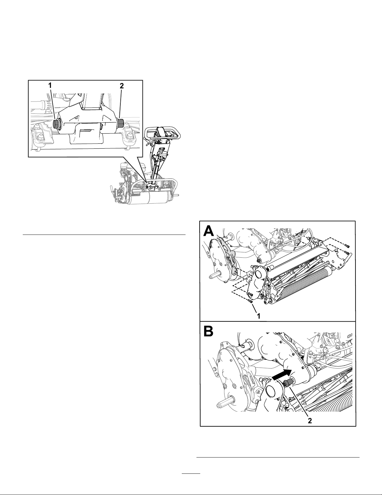
2.LoosentheboltandnutasshowninFigure33.
CuttingUnitMaintenance
BladeSafety
Usecarewhencheckingthecutting-unitreel.Wear
glovesandusecautionwhenservicingthereel.
Awornordamagedbladeorbedknifecanbreak,and
apiececouldbethrowntowardyouorbystanders,
resultinginseriouspersonalinjuryordeath.
•Inspectthebladesandbedknivesperiodicallyfor
excessivewearordamage.
•Usecarewhencheckingtheblades.Weargloves
andusecautionwhenservicingthem.Only
replaceorbacklapthebladesandbedknives;
neverstraightenorweldthem.
InstallingtheCuttingUnit
1.MovethekickstandtotheCUTTING-UNIT-SERVICE
position;refertoKickstand(page10).
2.Alignthecuttingunittotheframe.
Figure33
1.Bolt2.Nut
3.Pushthehandleasfarforwardaspossible.
4.Whilesupportingthehandle,torquetheboltand
nutthatyouloosenedinstep2to91to1 11Nm
(67to82ft-lb).
Note:Haveanassistanthelpyoutosupport
thehandleortorquethehardware.
5.Releasethehandle.
g289358
3.Use4socket-headscrewstosecurethecutting
unittotheframe(Figure34).
Figure34
1.Socket-headscrew2.Cutting-unit-drivecoupler
28
g304659
Page 29
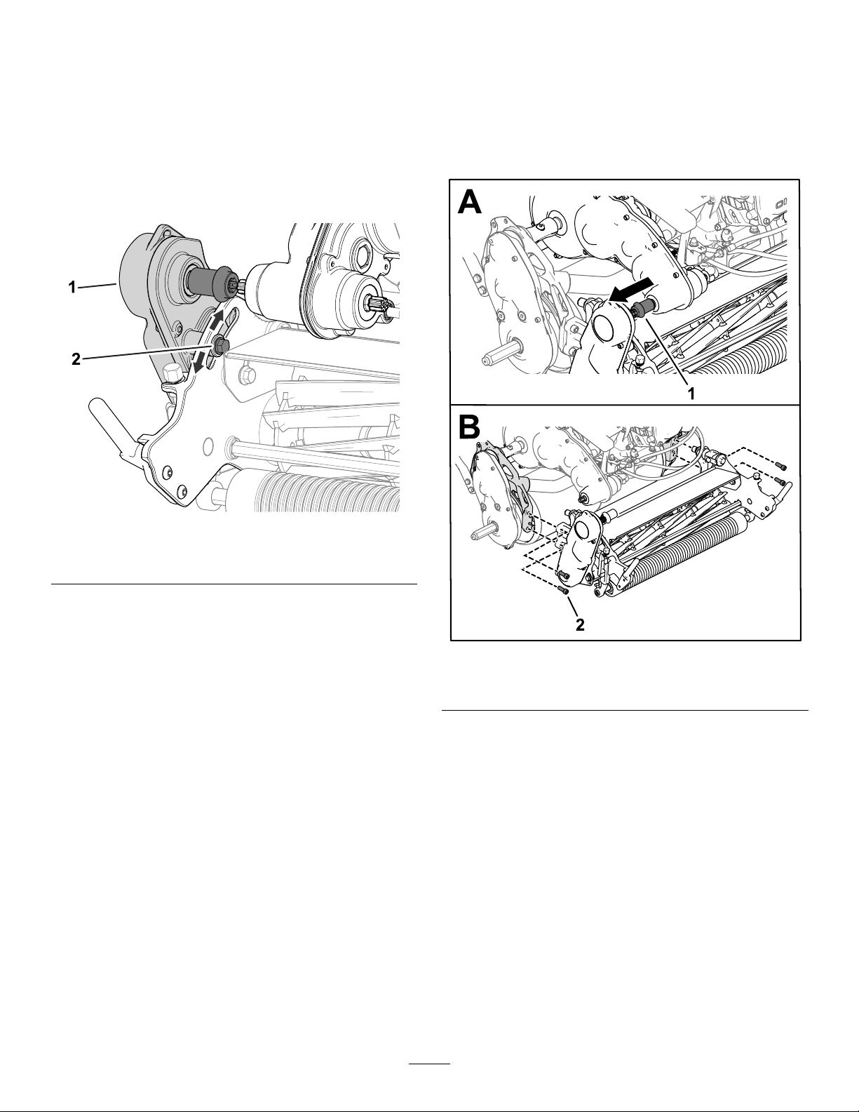
4.Slidethecutting-unit-drivecouplerontothe
transmissiondriveshaft(Figure34).
Thecouplershouldslideontothetransmission
driveshaftwithoutresistance.Ifthereis
resistance,ensurethatthereeldriveshaftand
thetransmissiondriveshaftarealigned.
Youcanadjustthereeldriveshaftpositionby
adjustingthereel-drive-assemblyposition:
A.LoosentheboltshowninFigure35.
RemovingtheCuttingUnit
1.MovethekickstandtotheCUTTING-UNIT-SERVICE
position;refertoKickstand(page10).
2.Removethegrassbasket(ifequipped).
3.Releasethecutting-unit-drivecouplerfromthe
transmissiondriveshaft(Figure36).
Figure35
1.Reel-driveassembly2.Bolt
B.Rotatethereel-driveassemblysothatthe
reeldriveshaftisproperlyalignedwiththe
transmissiondriveshaft.
C.Tightentheboltthatyoupreviously
loosened.
Ifresistancecontinues,adjusttheengineand
transmissionalignment;refertotheService
Manual.
5.Installthegrassbasket.
g304660
g304661
Figure36
1.Cutting-unit-drivecoupler2.Socket-headscrew
4.Removethesocket-headscrewsthatsecurethe
cuttingunittotheframe(Figure36).
5.Removethecuttingunitfromtheframe.
29
Page 30

BacklappingtheCutting
Unit
Tobacklapthecuttingunit,usetheAccessBacklap
Kit(ModelNo.139-4342)ortheBacklapKit(Model
No.04800);refertotheoperatinginstructionsinthe
kitInstallationInstructions.Contactyourauthorized
Torodistributortoacquireoneofthesekits.
Storage
StorageSafety
•Shutofftheengine,removethekey(ifequipped),
andwaitforallmovementtostopbeforeyouleave
theoperator’sposition.Allowthemachinetocool
beforeadjusting,servicing,cleaning,orstoringit.
•Donotstorethemachineorfuelcontainerwhere
thereisanopename,spark,orpilotlight,such
asonawaterheaterorotherappliance.
StoringtheMachine
1.Removeanygrassclippings,dirt,andgrime
fromtheexternalpartsoftheentiremachine,
especiallytheengine.Cleanthedirtandchaff
fromtheoutsideoftheenginecylinder-headns
andtheblowerhousing.
Important:Youcanwashthemachine
withmilddetergentandwater.Donot
pressure-washthemachine.Avoid
excessiveuseofwater,especiallynearthe
shift-leverplateandtheengine.
2.Forlong-termstorage(morethan30days)add
stabilizer/conditioneradditivetothefuelinthe
tank.
A.Runtheenginetodistributeconditionedfuel
throughthefuelsystemfor5minutes.
B.Eithershutofftheengine,allowittocool,
anddrainthefueltank,oroperatethe
engineuntilitshutsoff.
C.Starttheengineandrunituntilitshuts
off.Starttheengineagain,withthechoke
closed,untiltheenginedoesnotstart.
D.Disconnectthespark-plugwirefromthe
sparkplug.
E.Disposeofthefuelproperly .Recycleit
accordingtolocalcodes.
Note:Donotstorefuelcontaining
stabilizer/conditionerlongerthanthe
durationrecommendedbythefuel-stabilizer
manufacturer.
3.Checkandtightenallbolts,nuts,andscrews.
Repairorreplaceanypartthatiswornor
damaged.
4.Paintallscratchedorbaremetalsurfaces.Paint
isavailablefromyourauthorizedT orodistributor.
5.Storethemachineinaclean,drygarageor
storagearea.Coverthemachinetoprotectit
andkeepitclean.
30
Page 31

Notes:
Page 32

Notes:
Page 33

Notes:
Page 34

EEA/UKPrivacyNotice
Toro’sUseofYourPersonalInformation
TheT oroCompany(“T oro”)respectsyourprivacy .Whenyoupurchaseourproducts,wemaycollectcertainpersonalinformationaboutyou,eitherdirectly
fromyouorthroughyourlocalT orocompanyordealer.T orousesthisinformationtofullcontractualobligations-suchastoregisteryourwarranty ,
processyourwarrantyclaimortocontactyouintheeventofaproductrecall-andforlegitimatebusinesspurposes-suchastogaugecustomer
satisfaction,improveourproductsorprovideyouwithproductinformationwhichmaybeofinterest.Toromayshareyourinformationwithoursubsidiaries,
afliates,dealersorotherbusinesspartnersinconnectiontheseactivities.Wemayalsodisclosepersonalinformationwhenrequiredbylaworin
connectionwiththesale,purchaseormergerofabusiness.Wewillneversellyourpersonalinformationtoanyothercompanyformarketingpurposes.
RetentionofyourPersonalInformation
Torowillkeepyourpersonalinformationaslongasitisrelevantfortheabovepurposesandinaccordancewithlegalrequirements.Formoreinformation
[email protected].
Toro’sCommitmenttoSecurity
YourpersonalinformationmaybeprocessedintheUSoranothercountrywhichmayhavelessstrictdataprotectionlawsthanyourcountryofresidence.
Wheneverwetransferyourinformationoutsideofyourcountryofresidence,wewilltakelegallyrequiredstepstoensurethatappropriatesafeguardsare
inplacetoprotectyourinformationandtomakesureitistreatedsecurely.
AccessandCorrection
Youmayhavetherighttocorrectorreviewyourpersonaldata,orobjecttoorrestricttheprocessingofyourdata.Todoso,pleasecontactusbyemail
[email protected] orohashandledyourinformation,weencourageyoutoraisethisdirectlywithus.
PleasenotethatEuropeanresidentshavetherighttocomplaintoyourDataProtectionAuthority.
374-0282RevC
Page 35

TheToroWarranty
Two-Y earor1,500HoursLimitedWarranty
ConditionsandProductsCovered
TheToroCompanyanditsafliate,T oroWarrantyCompany,pursuant
toanagreementbetweenthem,jointlywarrantyourT oroCommercial
product(“Product”)tobefreefromdefectsinmaterialsorworkmanship
for2yearsor1,500operationalhours*,whicheveroccursrst.This
warrantyisapplicabletoallproductswiththeexceptionofAerators
(refertoseparatewarrantystatementsfortheseproducts).Wherea
warrantableconditionexists,wewillrepairtheProductatnocosttoyou
includingdiagnostics,labor,parts,andtransportation.Thiswarranty
beginsonthedatetheProductisdeliveredtotheoriginalretailpurchaser .
*Productequippedwithanhourmeter.
InstructionsforObtainingWarrantyService
YouareresponsiblefornotifyingtheCommercialProductsDistributoror
AuthorizedCommercialProductsDealerfromwhomyoupurchasedthe
Productassoonasyoubelieveawarrantableconditionexists.Ifyouneed
helplocatingaCommercialProductsDistributororAuthorizedDealer,or
ifyouhavequestionsregardingyourwarrantyrightsorresponsibilities,
youmaycontactusat:
ToroCommercialProductsServiceDepartment
ToroWarrantyCompany
811 1LyndaleAvenueSouth
Bloomington,MN55420-1196
952–888–8801or800–952–2740
E-mail:[email protected]
OwnerResponsibilities
Astheproductowner,youareresponsibleforrequiredmaintenanceand
adjustmentsstatedinyourOperator'sManual.Repairsforproductissues
causedbyfailuretoperformrequiredmaintenanceandadjustmentsarenot
coveredunderthiswarranty.
ItemsandConditionsNotCovered
Notallproductfailuresormalfunctionsthatoccurduringthewarranty
periodaredefectsinmaterialsorworkmanship.Thiswarrantydoesnot
coverthefollowing:
•Productfailureswhichresultfromtheuseofnon-T ororeplacement
parts,orfrominstallationanduseofadd-on,ormodiednon-Toro
brandedaccessoriesandproducts.
•Productfailureswhichresultfromfailuretoperformrecommended
maintenanceand/oradjustments.
•ProductfailureswhichresultfromoperatingtheProductinanabusive,
negligent,orrecklessmanner.
•Partsconsumedthroughusethatarenotdefective.Examplesofparts
whichareconsumed,orusedup,duringnormalProductoperation
include,butarenotlimitedto,brakepadsandlinings,clutchlinings,
blades,reels,rollersandbearings(sealedorgreasable),bedknives,
sparkplugs,castorwheelsandbearings,tires,lters,belts,andcertain
sprayercomponentssuchasdiaphragms,nozzles,andcheckvalves.
•Failurescausedbyoutsideinuence,including,butnotlimitedto,
weather,storagepractices,contamination,useofunapprovedfuels,
coolants,lubricants,additives,fertilizers,water ,orchemicals.
•Failureorperformanceissuesduetotheuseoffuels(e.g.gasoline,
diesel,orbiodiesel)thatdonotconformtotheirrespectiveindustry
standards.
•Normalnoise,vibration,wearandtear,anddeterioration.Normal
“wearandtear”includes,butisnotlimitedto,damagetoseatsdueto
wearorabrasion,wornpaintedsurfaces,scratcheddecalsorwindows.
Parts
Partsscheduledforreplacementasrequiredmaintenancearewarranted
fortheperiodoftimeuptothescheduledreplacementtimeforthatpart.
Partsreplacedunderthiswarrantyarecoveredforthedurationofthe
originalproductwarrantyandbecomethepropertyofT oro.T orowillmake
thenaldecisionwhethertorepairanyexistingpartorassemblyorreplace
it.T oromayuseremanufacturedpartsforwarrantyrepairs.
DeepCycleandLithium-IonBatteryWarranty
DeepcycleandLithium-Ionbatterieshaveaspeciedtotalnumber
ofkilowatt-hourstheycandeliverduringtheirlifetime.Operating,
recharging,andmaintenancetechniquescanextendorreducetotal
batterylife.Asthebatteriesinthisproductareconsumed,theamount
ofusefulworkbetweenchargingintervalswillslowlydecreaseuntilthe
batteryiscompletelywornout.Replacementofwornoutbatteries,
duetonormalconsumption,istheresponsibilityoftheproductowner.
Note:(Lithium-Ionbatteryonly):Pro-ratedafter2years.Refertothe
batterywarrantyforadditionalinformation.
LifetimeCrankshaftWarranty(ProStripe02657Model
Only)
TheProstripewhichisttedwithagenuineT oroFrictionDiscand
Crank-SafeBladeBrakeClutch(integratedBladeBrakeClutch(BBC)+
FrictionDiscassembly)asoriginalequipmentandusedbytheoriginal
purchaserinaccordancewithrecommendedoperatingandmaintenance
procedures,arecoveredbyaLifetimeWarrantyagainstenginecrankshaft
bending.Machinesttedwithfrictionwashers,BladeBrakeClutch(BBC)
unitsandothersuchdevicesarenotcoveredbytheLifetimeCrankshaft
Warranty.
MaintenanceisatOwner’sExpense
Enginetune-up,lubrication,cleaningandpolishing,replacementoflters,
coolant,andcompletingrecommendedmaintenancearesomeofthe
normalservicesT oroproductsrequirethatareattheowner’sexpense.
GeneralConditions
RepairbyanAuthorizedToroDistributororDealerisyoursoleremedy
underthiswarranty.
NeitherTheToroCompanynorToroWarrantyCompanyisliablefor
indirect,incidentalorconsequentialdamagesinconnectionwiththe
useoftheToroProductscoveredbythiswarranty,includingany
costorexpenseofprovidingsubstituteequipmentorserviceduring
reasonableperiodsofmalfunctionornon-usependingcompletion
ofrepairsunderthiswarranty.ExceptfortheEmissionswarranty
referencedbelow,ifapplicable,thereisnootherexpresswarranty.All
impliedwarrantiesofmerchantabilityandtnessforusearelimitedto
thedurationofthisexpresswarranty.
Somestatesdonotallowexclusionsofincidentalorconsequential
damages,orlimitationsonhowlonganimpliedwarrantylasts,sotheabove
exclusionsandlimitationsmaynotapplytoyou.Thiswarrantygivesyou
speciclegalrights,andyoumayalsohaveotherrightswhichvaryfrom
statetostate.
NoteRegardingEmissionsWarranty
TheEmissionsControlSystemonyourProductmaybecoveredby
aseparatewarrantymeetingrequirementsestablishedbytheU.S.
EnvironmentalProtectionAgency(EP A)and/ortheCaliforniaAirResources
Board(CARB).Thehourlimitationssetforthabovedonotapplytothe
EmissionsControlSystemWarranty.RefertotheEngineEmissionControl
WarrantyStatementsuppliedwithyourproductorcontainedintheengine
manufacturer’sdocumentation.
CountriesOtherthantheUnitedStatesorCanada
CustomerswhohavepurchasedT oroproductsexportedfromtheUnitedStatesorCanadashouldcontacttheirT oroDistributor(Dealer)toobtain
guaranteepoliciesforyourcountry ,province,orstate.IfforanyreasonyouaredissatisedwithyourDistributor'sserviceorhavedifcultyobtaining
guaranteeinformation,contactyourAuthorizedToroServiceCenter .
374-0253RevF
Page 36

CaliforniaProposition65WarningInformation
Whatisthiswarning?
Youmayseeaproductforsalethathasawarninglabellikethefollowing:
WARNING:CancerandReproductiveHarm—www.p65Warnings.ca.gov.
WhatisProp65?
Prop65appliestoanycompanyoperatinginCalifornia,sellingproductsinCalifornia,ormanufacturingproductsthatmaybesoldinorbroughtinto
California.ItmandatesthattheGovernorofCaliforniamaintainandpublishalistofchemicalsknowntocausecancer,birthdefects,and/orother
reproductiveharm.Thelist,whichisupdatedannually,includeshundredsofchemicalsfoundinmanyeverydayitems.ThepurposeofProp65isto
informthepublicaboutexposuretothesechemicals.
Prop65doesnotbanthesaleofproductscontainingthesechemicalsbutinsteadrequireswarningsonanyproduct,productpackaging,orliteraturewith
theproduct.Moreover,aProp65warningdoesnotmeanthataproductisinviolationofanyproductsafetystandardsorrequirements.Infact,the
CaliforniagovernmenthasclariedthataProp65warning“isnotthesameasaregulatorydecisionthataproductis‘safe’or‘unsafe.’”Manyofthese
chemicalshavebeenusedineverydayproductsforyearswithoutdocumentedharm.Formoreinformation,gotohttps://oag.ca.gov/prop65/faqs-view-all
AProp65warningmeansthatacompanyhaseither(1)evaluatedtheexposureandhasconcludedthatitexceedsthe“nosignicantrisklevel”;or(2)
haschosentoprovideawarningbasedonitsunderstandingaboutthepresenceofalistedchemicalwithoutattemptingtoevaluatetheexposure.
Doesthislawapplyeverywhere?
Prop65warningsarerequiredunderCalifornialawonly.ThesewarningsareseenthroughoutCaliforniainawiderangeofsettings,includingbutnot
limitedtorestaurants,grocerystores,hotels,schools,andhospitals,andonawidevarietyofproducts.Additionally,someonlineandmailorder
retailersprovideProp65warningsontheirwebsitesorincatalogs.
.
HowdotheCaliforniawarningscomparetofederallimits?
Prop65standardsareoftenmorestringentthanfederalandinternationalstandards.TherearevarioussubstancesthatrequireaProp65warning
atlevelsthatarefarlowerthanfederalactionlimits.Forexample,theProp65standardforwarningsforleadis0.5μg/day,whichiswellbelow
thefederalandinternationalstandards.
Whydon’tallsimilarproductscarrythewarning?
•ProductssoldinCaliforniarequireProp65labellingwhilesimilarproductssoldelsewheredonot.
•AcompanyinvolvedinaProp65lawsuitreachingasettlementmayberequiredtouseProp65warningsforitsproducts,butothercompanies
makingsimilarproductsmayhavenosuchrequirement.
•TheenforcementofProp65isinconsistent.
•CompaniesmayelectnottoprovidewarningsbecausetheyconcludethattheyarenotrequiredtodosounderProp65;alackofwarningsfora
productdoesnotmeanthattheproductisfreeoflistedchemicalsatsimilarlevels.
WhydoesToroincludethiswarning?
Torohaschosentoprovideconsumerswithasmuchinformationaspossiblesothattheycanmakeinformeddecisionsabouttheproductstheybuyand
use.T oroprovideswarningsincertaincasesbasedonitsknowledgeofthepresenceofoneormorelistedchemicalswithoutevaluatingthelevelof
exposure,asnotallthelistedchemicalsprovideexposurelimitrequirements.WhiletheexposurefromT oroproductsmaybenegligibleorwellwithinthe
“nosignicantrisk”range,outofanabundanceofcaution,T orohaselectedtoprovidetheProp65warnings.Moreover ,ifTorodoesnotprovidethese
warnings,itcouldbesuedbytheStateofCaliforniaorbyprivatepartiesseekingtoenforceProp65andsubjecttosubstantialpenalties.
RevA
 Loading...