

Page 1
FormNo.3371-939RevB
GrandStand
®
Mower
With122cmTURBOFORCE
®
CuttingUnit
ModelNo.74568TE—SerialNo.312000001andUp
g015545
ToregisteryourproductordownloadanOperator'sManualorPartsCatalogatnocharge,gotowww.T oro.com.OriginalInstructions(EN)
Page 2
ThisproductcomplieswithallrelevantEuropean
directives,fordetailspleaseseetheseparateproduct
specicDeclarationofConformity(DOC)sheet.
ThissparkignitionsystemcomplieswithCanadian
ICES-002.
WARNING
Removingstandardoriginalequipmentpartsand
accessoriesmayalterthewarranty,traction,and
safetyofthemachine.FailuretouseoriginalToro
partscouldcauseseriousinjuryordeath.Making
unauthorizedchangestotheengine,fuelorventing
system,mayviolateregulations.
Replaceallpartsincluding,butnotlimitedto,tires,
belts,blades,andfuelsystemcomponentswith
originalT oroparts.
Introduction
Thisrotary-blade,ridinglawnmowerisintended
tobeusedbyprofessional,hiredoperatorsor
residentialhomeowners.Itisdesignedprimarily
forcuttinggrassonwell-maintainedlawnson
residentialorcommercialproperties.Itisnot
designedforcuttingbrushorforagriculturaluses.
Readthisinformationcarefullytolearnhowtooperate
andmaintainyourproductproperlyandtoavoidinjury
andproductdamage.Youareresponsibleforoperating
theproductproperlyandsafely.
YoumaycontactTorodirectlyatwww .T oro.comfor
productandaccessoryinformation,helpndingadealer,
ortoregisteryourproduct.
Wheneveryouneedservice,genuineToroparts,
oradditionalinformation,contactanAuthorized
ServiceDealerorToroCustomerServiceandhave
themodelandserialnumbersofyourproductready .
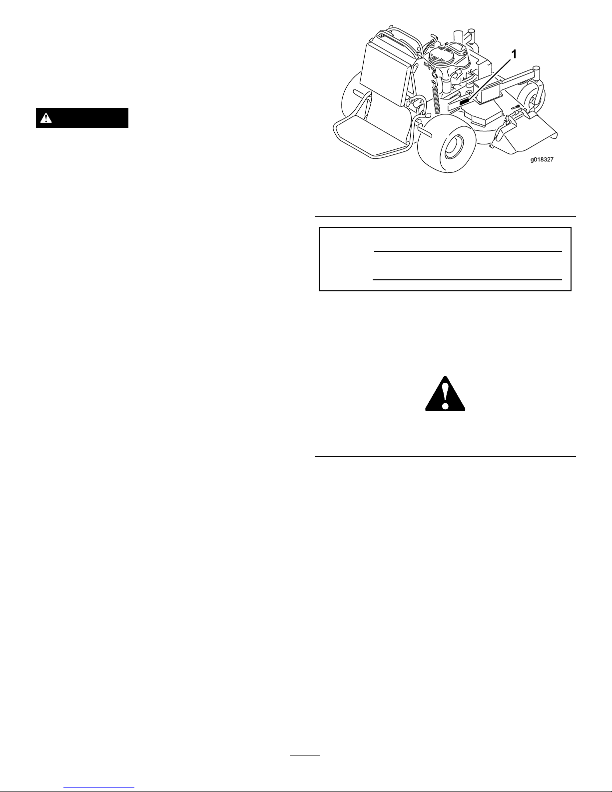
Figure1identiesthelocationofthemodelandserial
numbersontheproduct.Writethenumbersinthe
spaceprovided.
g018327
Figure1
1.Locationofthemodelandserialnumbers
ModelNo.
SerialNo.
Thismanualidentiespotentialhazardsandhassafety
messagesidentiedbythesafetyalertsymbol(
Figure2),
whichsignalsahazardthatmaycauseseriousinjury
ordeathifyoudonotfollowtherecommended
precautions.
Figure2
1.Safetyalertsymbol
Thismanualusestwootherwordstohighlight
information.Importantcallsattentiontospecial
mechanicalinformationandNoteemphasizesgeneral
informationworthyofspecialattention.
©2012—TheT oro®Company
8111LyndaleAvenueSouth
Bloomington,MN55420
2
Contactusatwww.Toro.com.
PrintedintheUSA.
AllRightsReserved
Page 3

Contents
Introduction.................................................................2
Safety...........................................................................4
GeneralLawnMowerSafety.................................4
ToroMowerSafety...............................................5
SoundPressure.....................................................6
SoundPower........................................................6
VibrationLevel.....................................................6
SlopeIndicator.....................................................7
SafetyandInstructionalDecals.............................8
ProductOverview......................................................13
Controls.............................................................13
Specications.....................................................14
Operation...................................................................15
AddingFuel.......................................................15
CheckingtheEngineOilLevel............................16
BreakingInaNewMachine................................16
ThinkSafetyFirst...............................................16
OperatingtheParkingBrake...............................16
OperatingtheMowerBladeControlSwitch
(PTO)............................................................17
OperatingtheThrottle.......................................17
OperatingtheChoke..........................................17
OperatingtheIgnitionSwitch.............................18
UsingtheFuelShut-OffValve............................18
StartingandStoppingtheEngine........................18
TheSafetyInterlockSystem................................20
OperatingthePlatform......................................21
DrivingForwardorBackward.............................21
StoppingtheMachine.........................................22
UsingtheRotationIndicator...............................23
PushingtheMachinebyHand.............................23
TransportingMachines.......................................23
LoadingMachines..............................................24
SideDischargingorMulchingtheGrass..............25
AdjustingtheHeight-of-Cut...............................25
AdjustingtheFlowBafe...................................25
PositioningtheFlowBafe.................................26
UsingtheMid-SizeWeight..................................26
Maintenance...............................................................28
RecommendedMaintenanceSchedule(s)................28
PremaintenanceProcedures....................................29
RaisingtheMowerforAccess.............................29
ReleasetheCushionforRearAccess...................30
Lubrication.............................................................31
HowtoGrease...................................................31
LubricatingtheMachine.....................................31
GreasingtheFrontCasterPivots.........................31
LubricateCasterWheelHubs.............................32
EngineMaintenance...............................................33
ServicingtheAirCleaner....................................33
ServicingtheEngineOil.....................................33
ServicingtheSparkPlug.....................................36
FuelSystemMaintenance.......................................37
DrainingtheFuelTank.......................................37
ServicingtheFuelFilter......................................38
ElectricalSystemMaintenance................................38
ServicingtheBattery...........................................38
ServicingtheFuses.............................................40
DriveSystemMaintenance.....................................40
AdjustingtheTracking.......................................40
CheckingtheTirePressure.................................42
AdjustingtheCasterPivotBearing......................42
ServicingtheCasterWheelandBearings.............42
AdjustingtheElectricClutch..............................43
CoolingSystemMaintenance..................................44
CleaningtheAirIntakeScreen............................44
CleaningtheCoolingSystem...............................44
BrakeMaintenance.................................................44
ServicingtheBrake.............................................44
BeltMaintenance....................................................46
ReplacingtheMowerDeckBelt..........................46
ReplacingthePumpDriveBelt...........................47
ControlsSystemMaintenance.................................48
AdjustingtheMotionControlHandle
Positions........................................................48
HydraulicSystemMaintenance...............................50
ServicingtheHydraulicSystem...........................50
MowerDeckMaintenance......................................53
ServicingtheCuttingBlades...............................53
CorrectingtheMowerQualityofCut..................55
ReplacingtheGrassDeector.............................57
Cleaning.................................................................58
CleaningUndertheMower.................................58
WasteDisposal...................................................58
Storage.......................................................................59
CleaningandStorage..........................................59
Troubleshooting.........................................................60
Schematics.................................................................62
3
Page 4

Safety
Improperlyusingormaintainingthismowercan
resultininjury.T oreducethepotentialforinjury,
complywiththesesafetyinstructions.
Torodesignedandtestedthismowerforreasonablysafe
service;however,failuretocomplywiththefollowing
instructionsmayresultinpersonalinjury.
Toensuremaximumsafety,bestperformance,and
togainknowledgeoftheproduct,itisessential
thatyouandanyotheroperatorofthemowerread
andunderstandthecontentsofthismanualbefore
theengineiseverstarted.Payparticularattention
tothesafetyalertsymbol(
Figure2)whichmeans
Caution,Warning,orDanger—“personalsafety
instruction.”Readandunderstandtheinstruction
becauseithastodowithsafety .Failuretocomply
withtheinstructionmayresultinpersonalinjury.
GeneralLawnMowerSafety
Thefollowinginstructionshavebeenadaptedfromthe
standardEN836:1997.
Thiscuttingmachineiscapableofamputatinghands
andfeetandthrowingobjects.Failuretoobservethe
followingsafetyinstructionscouldresultinserious
injuryordeath.
Training
•Readtheinstructionscarefully.Befamiliarwiththe
controlsandtheproperuseoftheequipment.
•Neverallowchildrenorpeopleunfamiliarwiththese
instructionstousethemower.Localregulationscan
restricttheageoftheoperator.
•Keepinmindthattheoperatororuserisresponsible
foraccidentsorhazardsoccurringtootherpeopleor
theirproperty.
•Understandexplanationsforallpictogramsusedon
themowerorintheinstructions.
•Donotcarrypassengers.
•Alloperatorsshouldseekandobtainprofessional
andpracticalinstruction.
•Usecareandconcentrationwhenworkingwith
machines.
•Thecontrolofamachineonaslopewillnotbe
regainedbytheapplicationofthebrake.
Themainreasonsforlossofcontrolare:
–insufcientwheelgrip
–beingdriventoofast
–inadequatebraking
–thetypeofmachineisunsuitableforit'stask
–lackofawarenessoftheeffectofground
conditions,especiallyslopes
–incorrectloaddistribution
Gasoline
WARNING-Gasolineishighlyammable.Takethe
followingprecautions.
•Storefuelincontainersspecicallydesignedforthis
purpose.
•Refueloutdoorsonlyanddonotsmokewhile
refueling.
•Addfuelbeforestartingtheengine.Neverremove
thecapofthefueltankoraddgasolinewhilethe
engineisrunningorwhentheengineishot.
•Ifgasolineisspilled,donotattempttostartthe
enginebutmovethemowerawayfromtheareaof
spillageandavoidcreatinganysourceofignition
untilgasolinevaporshavedissipated.
•Replaceallfueltankandcontainercapssecurely.
Preparation
•Whilemowing,alwayswearsubstantialfootwearand
longtrousers.Donotoperatetheequipmentwhen
barefootorwearingopensandals.
•Thoroughlyinspecttheareawheretheequipmentis
tobeusedandremoveallstones,sticks,wires,bones
andotherforeignobjects.
•Beforeusing,alwaysvisuallyinspecttoseethat
guards,andsafetydevices,suchasdeectorsand/or
grasscatchers,areinplaceandworkingcorrectly.
•Beforeusing,alwaysvisuallyinspecttoseethatthe
blades,bladeboltsandcutterassemblyarenotworn
ordamaged.Replacewornordamagedbladesand
boltsinsetstopreservebalance.
Starting
•Disengageallbladeanddriveclutchesandshiftinto
neutralbeforestartingtheengine.
•Starttheengineorswitchonthemotorcarefully
accordingtoinstructionsandwithfeetwellaway
fromtheblade(s)andnotinfrontofthedischarge
chute.
Operation
•Lightningcancausesevereinjuryordeath.If
lightningisseenorthunderisheardinthearea,do
notoperatethemachine;seekshelter.
4
Page 5

•Nevermowwhilepeople,especiallychildren,orpets
arenearby .
•Mowonlyindaylightoringoodarticiallight.
•Avoidoperatingthelawnmowerinwetgrass,where
feasible.
•Stayalertforholesintheterrainandotherhidden
hazards.
•Neverdirectdischargeofmaterialtowards
bystanders.
•Donotputhandsorfeetnearorunderrotatingparts.
Keepclearofthedischargeopeningatalltimes.
•Useextremecautionwhenreversingorpullinga
pedestriancontrolledlawnmowertowardsyou.
•Walk,neverrun.
•Slopes:
–Donotmowexcessivelysteepslopes.Donot
mowslopesgreaterthan20degrees.
–Exerciseextremecautionwhenonslopes.
–Mowacrossthefaceofslopes,neverupand
downandexerciseextremecautionwhen
changingdirectiononslopes.
–Alwaysbesureofyourfootingonslopes.
•Uselowthrottlesettingswhenengagingthe
traction-clutch,especiallyinhighgears.Reduce
speedonslopesandinsharpturnstoprevent
overturningorlossofcontrol.
•Stopthebladewhencrossingsurfacesotherthan
grassandwhentransportingthelawnmowertoand
fromtheareatobemowed.
•Donotoperatetheengineinaconnedspacewhere
dangerouscarbonmonoxidefumescancollect.
•Stoptheengine
–wheneveryouleavethelawnmower.
–beforerefueling.
–beforeremovingthegrasscatcher.
•Stoptheengineanddisconnectthespark-plugwire
orturnoffandremovethekey.
–beforeclearingblockagesoruncloggingchute.
–beforechecking,cleaningorworkingonthelawn
mower.
–afterstrikingaforeignobject,inspectthelawn
mowerfordamageandmakerepairsbefore
restartingandoperatingthelawnmower.
–iflawnmowerstartstovibrateabnormally(check
immediately).
•Watchoutfortrafcwhencrossingornearroadways.
•Beforeleavingtheoperator'sposition
–disengagethepowertake-offandlowerthe
attachments.
–changeintoneutralandsettheparkingbrake.
–stoptheengineandremovethekey.
MaintenanceandStorage
•Keepallnuts,boltsandscrewstighttobesurethe
equipmentisinsafeworkingcondition.
•Donotusepressurecleaningequipmentonmachine.
•Neverstoretheequipmentwithgasolineinthetank
andinsideabuildingwherefumescanreachanopen
ameorspark.
•Allowtheenginetocoolbeforestoringinany
enclosure.
•Toreducetherehazard,keeptheengine,silencer,
batterycompartmentandgasolinestoragefreeof
grass,leaves,orexcessivegrease.
•Checkgrasscatchercomponentsandthedischarge
guardfrequentlyandreplacewithmanufacturer's
recommendedparts,whennecessary.
•Replacewornordamagedpartsforsafety .
•Replacefaultysilencers.
•Ifthefueltankhastobedrained,dothisoutdoors.
•Donotchangetheenginegovernorsettingsor
overspeedtheengine.Operatinganengineat
excessivespeedcanincreasethehazardofpersonal
injury.
•Onmultibladedlawnmowers,takecareasrotating
oneblademaycauseotherstorotate.
•Becarefulduringadjustmentofthelawnmowerto
prevententrapmentofthengersbetweenmoving
bladesandxedpartsofthelawnmower.
•Toensurethebestperformanceandsafety ,
purchaseonlygenuineT ororeplacementparts
andaccessories.Donotuse
will t
partsand
accessories;theymaycauseasafetyhazard.
ToroMowerSafety
Thefollowinglistcontainssafetyinformationspecic
toToroproductsandothersafetyinformationyoumust
know .
Thisproductiscapableofamputatinghandsand
feetandthrowingobjects.Alwaysfollowallsafety
instructionstoavoidseriousinjuryordeath.
Thisproductisdesignedforcuttingandrecyclinggrass
or,whenequippedwithagrassbagger,forcatchingcut
grass.Anyuseforpurposesotherthanthesecould
provedangeroustouserandbystanders.
5
Page 6

GeneralOperation
•Besuretheareaisclearofotherpeoplebefore
mowing.Stopthemachineifanyoneentersthearea.
•Donottouchequipmentorattachmentpartswhich
maybehotfromoperation.Allowtocoolbefore
attemptingtomaintain,adjustorservice.
•UseonlyToroapprovedattachments.Warrantymay
bevoidedifusedwithunapprovedattachments.
•Checkcarefullyforoverheadclearances(i.e.
branches,doorways,electricalwires)beforeoperating
underanyobjectsanddonotcontactthem.
•Slowdownbeforemakingturnsanduseextra
caution.
•Usecautionwhenridingtheplatformovercurbs,
rocks,roots,orotherobstructions.
•Lookbehindanddownbeforebackinguptobesure
ofaclearpath.Useextracarewhenoperationin
reverse.
•Neverjerkthecontrols;useasteadymotion.
•Donotcarrypassengers.
SlopeOperation
Allslopesandrampsrequireextracaution.Ifyoufeel
uneasyonaslope,donotmowit.
•Removeobstaclessuchasrocks,treelimbs,etc.from
themowingarea.
•Watchforholes,rutsorbumps.Tallgrasscanhide
obstacles.
•Usecautionneardrop-offs,ditches,orembankments.
Themachinecouldsuddenlyturnoverifawheel
goesovertheedgeofaclifforditch,orifanedge
cavesin.
•Useextracarewithgrasscatchersorother
attachments.Thesecanchangethestabilityofthe
machine.
•Keepallmovementonslopesslowandgradual.Do
notmakesuddenchangesinspeedordirection.
•Mowslopessidetoside.
Service
•Neverstorethemachineorfuelcontainerinside
wherethereisanopename,suchasnearawater
heaterorfurnace.
•Keepnutsandboltstight,especiallytheblade
attachmentbolts.Keepequipmentingood
condition.
•Nevertamperwithsafetydevices.Checksafety
systemsforproperoperationbeforeeachuse.
•Useonlygenuinereplacementpartstoensurethat
originalstandardsaremaintained.
•Checkbrakeoperationfrequently.Adjustandservice
asrequired.
SoundPressure
Thisunithasasoundpressurelevelattheoperator’s
earof93dBA,whichincludesanUncertaintyValue(K)
of1dBA.
Thesoundpressurelevelwasdeterminedaccordingto
theproceduresoutlinedinEN836.
SoundPower
Thisunithasaguaranteedsoundpowerlevelof105
dBA,whichincludesanUncertaintyValue(K)of1dBA.
Thesoundpowerlevelwasdeterminedaccordingtothe
proceduresoutlinedinISO11094.
VibrationLevel
Hand-Arm
Measuredvibrationlevelforrighthand=1.1m/s
2
Measuredvibrationlevelforlefthand=0.8m/s
2
UncertaintyValue(K)=0.6m/s
2
Measuredvaluesweredeterminedaccordingtothe
proceduresoutlinedinEN836.
WholeBody
Measuredvibrationlevel=0.74m/s
2
UncertaintyValue(K)=0.37m/s
2
Measuredvaluesweredeterminedaccordingtothe
proceduresoutlinedinEN836.
6
Page 7
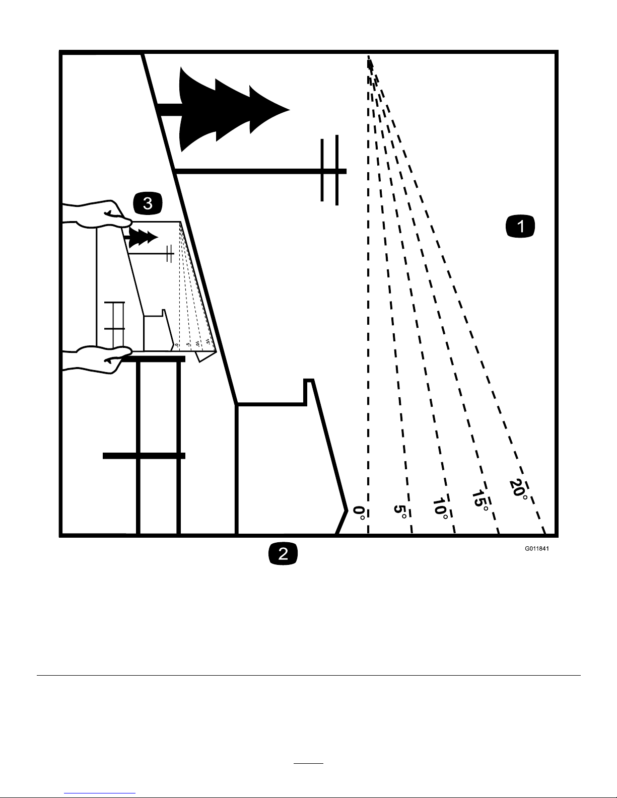
SlopeIndicator
G011841
Figure3
Thispagemaybecopiedforpersonaluse.
1.Themaximumslopeyoucansafelyoperatethemachineonis20degrees.Usetheslopecharttodeterminethedegreeofslope
ofhillsbeforeoperating.Donotoperatethismachineonaslopegreaterthan20degrees.Foldalongtheappropriateline
tomatchtherecommendedslope.
2.Alignthisedgewithaverticalsurface,atree,building,fencepole,etc.
3.Exampleofhowtocompareslopewithfoldededge.
7
Page 8
SafetyandInstructional
Decals
Safetydecalsandinstructionsareeasilyvisibletotheoperatorandarelocatednearanyareaof
potentialdanger.Replaceanydecalthatisdamagedorlost.
93-7010
1.Thrownobjecthazard—keepbystandersasafedistance
fromthemachine.
2.Thrownobjecthazard,mower—keepthedeectorinplace.
3.Cutting/dismembermentofhandorfoot—stayawayfrom
movingparts.
93-7818
1.Warning—readtheOperator'sManualforinstructionson
torquingthebladebolt/nutto115-149N-m(85-110ft-lb).
106-5517
1.Warning–DoNottouchthehotsurface.
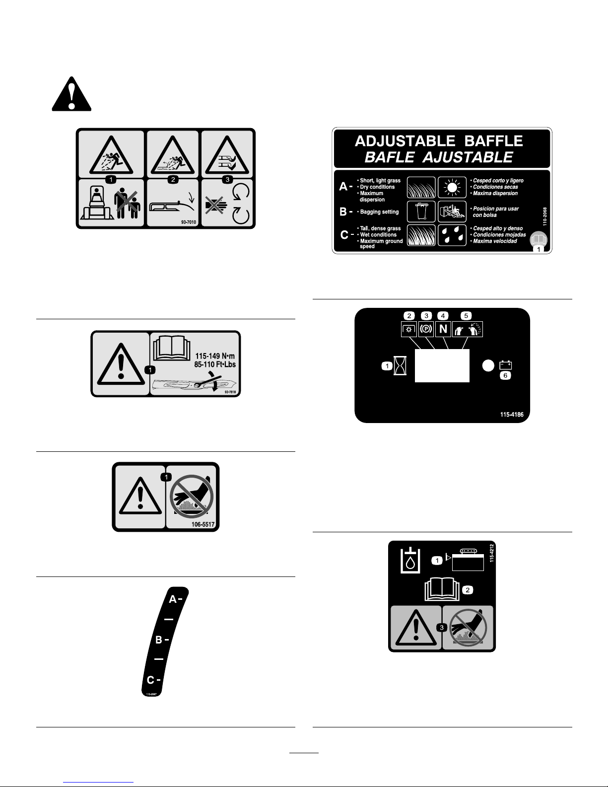
110-2067
110-2068
1.ReadtheOperator'sManual.
115-4186
1.Interval
2.PowerT ake-off(PTO)
3.Parkingbrake
4.Neutral
5.Operatorpresenceswitch
6.Battery
115-4212
1.Hydraulicoillevel3.Warning—donottouchthe
hotsurface.
2.ReadtheOperator's
Manual.
8
Page 9
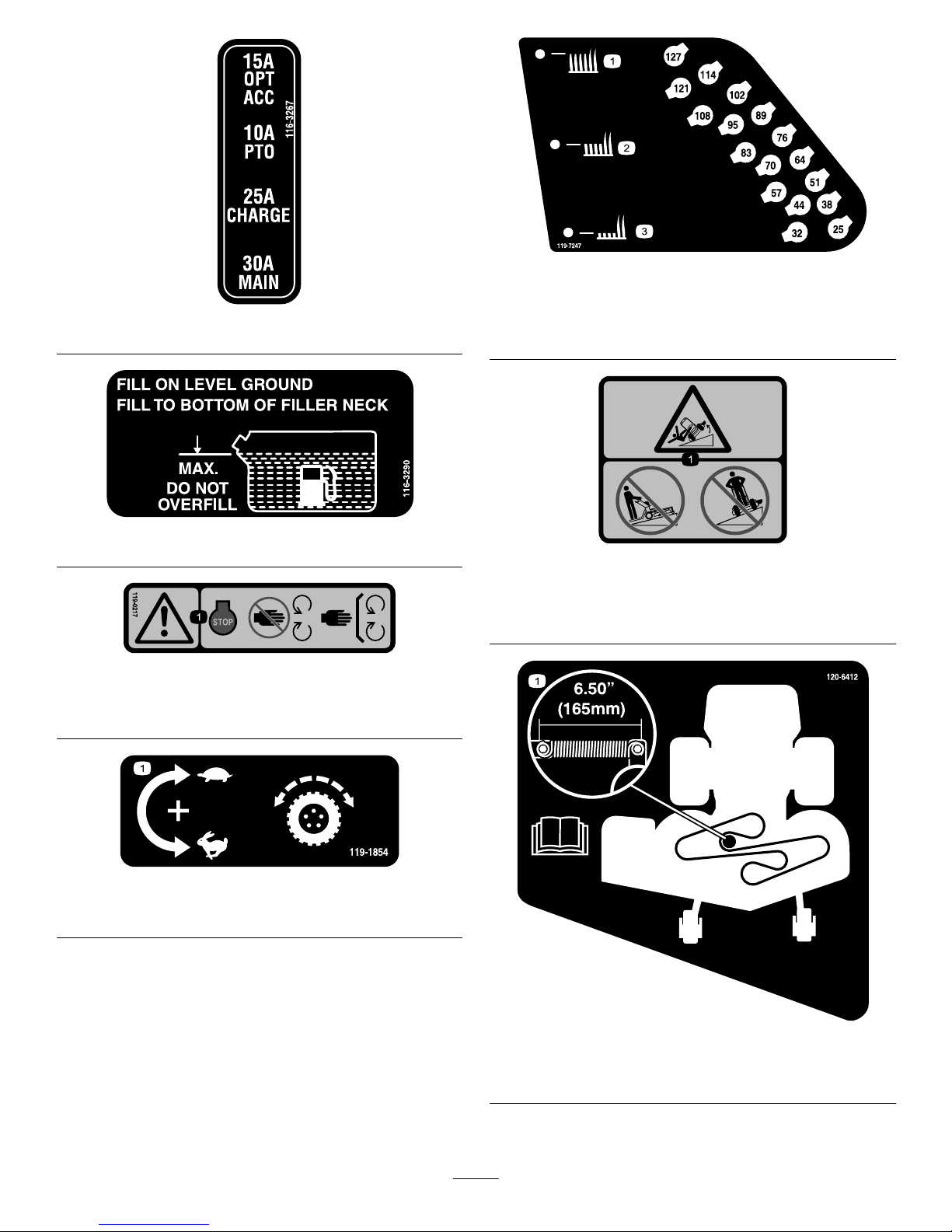
116–3267
116-3290
119-0217
1.Warning—stoptheengine;stayawayfrommovingparts;
keepallguardsandshieldsinplace.
119-1854
1.Adjustmentknobfortractiondrivespeed.
119-7247
1.Heightofcut(HOC)—high3.Heightofcut(HOC)—low
2.Heightofcut
(HOC)—medium
119-8663
>10∞
>20∞
119–8663
1.Tippinghazard—donotmowupordownslopesgreater
than10degrees;donotmowacrossslopesgreaterthan
20degrees.
120-6412
1.Belttensionadjustment;readtheOperator'sManualfor
moreinformation.
9
Page 10
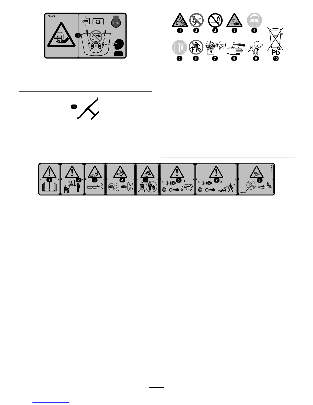
120-6424
1.Cutting/dismembermenthazard,hand—disengagethe
powertake-off(PTO),stoptheengineandwatchforall
movingpartstostop.
Manufacturer'sMark
1.Indicatesthebladeisidentiedasapartfromtheoriginal
machinemanufacturer.
BatterySymbols
Someorallofthesesymbolsareonyourbattery
1.Explosionhazard
6.Keepbystandersasafe
distancefromthebattery.
2.Nore,opename,or
smoking.
7.Weareyeprotection;
explosivegasescan
causeblindnessandother
injuries
3.Causticliquid/chemical
burnhazard
8.Batteryacidcancause
blindnessorsevereburns.
4.Weareyeprotection9.Flusheyesimmediately
withwaterandgetmedical
helpfast.
5.ReadtheOperator's
Manual.
10.Containslead;donot
discard.
117–3626
1.Warning—readtheOperator'sManual.5.Thrownobjecthazard—keepbystandersasafedistancefrom
themachine.
2.Warning—donotoperatethismachineunlessyouaretrained.6.Warning—engagetheparkingbrake,stoptheengine
andremovethesparkplugwirebeforeperformingany
maintenanceonthemachine.
3.Thrownobjecthazard—keepdeectorinplace.
7.Warning—engagetheparkingbrakeandstoptheengine
beforeleavingthemachine.
4.Cutting,dismembermenthazardofhandorfoot—stayaway
frommovingpartsandkeepallguardsandshieldsinplace.
8.Slidingandlossofcontrolhazard—donotoperatethe
machineneardrop-offsorwater;keepasafedistancefrom
drop-offs.
10
Page 11
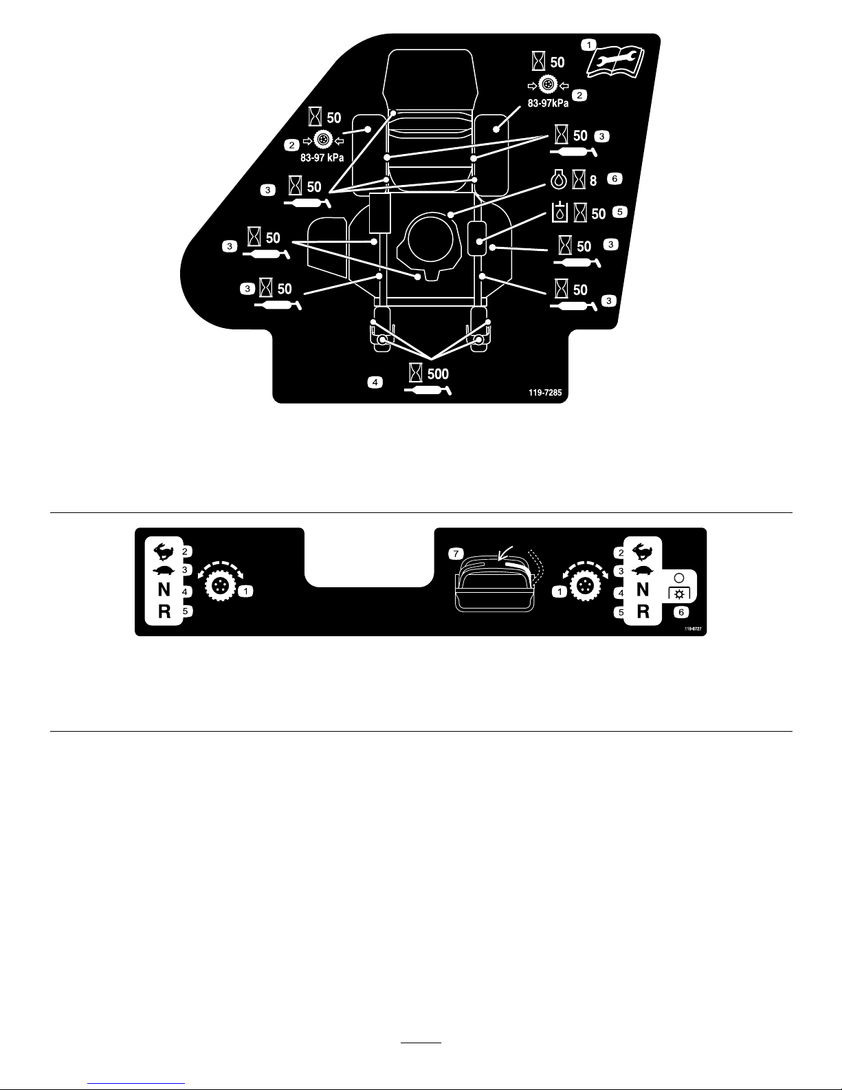
119-7285
1.ReadtheOperator'sManualbefore
performinganymaintenance.
3.Lubricateevery50hours
5.Checkthehydraulicoilevery50hours
2.Checkthedrivewheeltirepressure
every50hours
4.Lubricatethecasterwheelevery500
hours
6.Checktheengineoilevery8hours
119-8727
1.Tractioncontrol
3.Slow
5.Reverse
7.Operatorpresenceswitch
2.Fast4.Neutral
6.PowerT ake-off
(PTO)—disengage
11
Page 12

120-6464
1.Parkingbrake—engage
3.PowerT ake-off
(PTO)—engage
5.Enginespeed
7.Continuousvariablesetting
2.Parkingbrake—disengage
4.PowerT ake-off
(PTO)—disengage
6.Fast
8.Slow
12
Page 13
ProductOverview
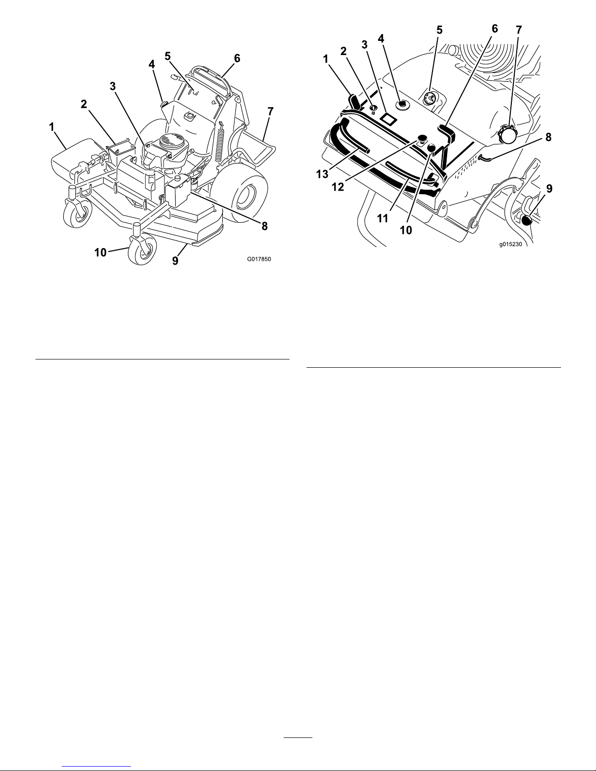
G017850
Figure4
1.Sidedischargechute6.Controllevers
2.Battery
7.Platform(downposition)
3.Engine8.Hydraulictank
4.Fueltank9.Mowerdeck
5.Controls
10.Frontcasterwheel
Controls
Becomefamiliarwithallthecontrols(Figure5)before
youstarttheengineandoperatethemachine.
g015230
3
4
5
6
7
8
9
10
11
12
13
Figure5
1.Parkingbrakelever
8.Height-of-cutpin
2.Choke9.Platformlatch
3.Hourmeter10.Throttlecontrol
4.Ignitionswitch11.Rightmotioncontrollever
5.Fuelgauge
12.Bladecontrolswitch(PTO)
6.Height-of-cutlever13.Leftmotioncontrollever
7.Fuelcap
HourMeter
Thehourmeterrecordsthenumberofhourstheengine
hasoperated.Itoperateswhentheengineisrunning.
Usethesetimesforschedulingregularmaintenance
(Figure6).
FuelGauge
Thefuelgaugeislocatedonthetop,middleofthetank
(Figure5).
SafetyInterlockIndicators
Therearesymbolsonthehourmeterandindicatewith
ablacktrianglethattheinterlockcomponentisinthe
correctposition(Figure6).
BatteryIndicatorLight
IftheignitionkeyisturnedtotheOnpositionforafew
seconds,thebatteryvoltagewillbedisplayedinthearea
wherethehoursarenormallydisplayed.
Thebatterylightturnsonwhentheignitionisturned
onandwhenthechargeisbelowthecorrectoperating
level(Figure6).
13
Page 14
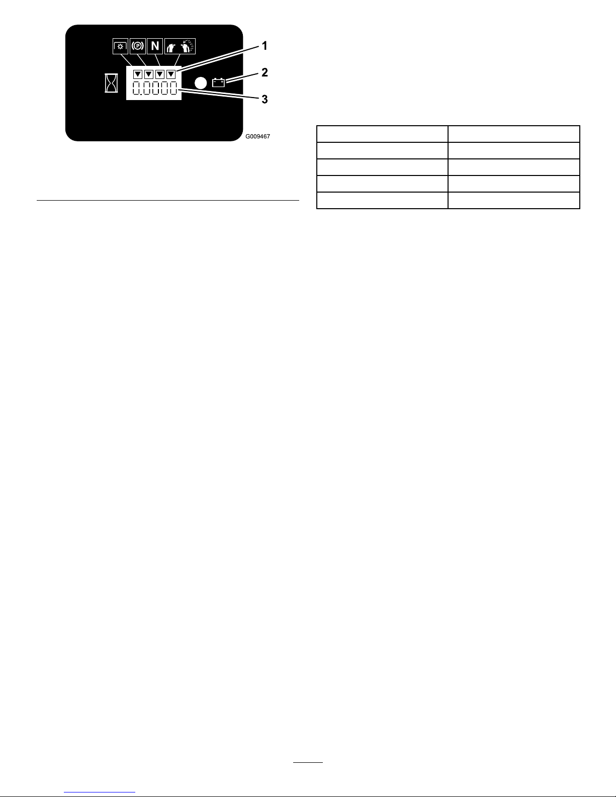
Figure6
1.Safetyinterlocksymbols
3.Hourmeter
2.Batterylight
ThrottleControl
ThethrottlecontrolisvariablebetweenFastandSlow.
Choke
Usethechoketostartacoldengine.
BladeControlSwitch(PTO)
Thebladecontrolswitch(PTO)isusedtoengage
theelectricclutchtodrivethemowerbladeswiththe
rightsidemotioncontrolleverinthecenter,un-locked
position.Pulltheswitchuptoengagethebladesand
release.Todisengagetheblades,pushthebladecontrol
switch(PTO)downormoveorreleasetherightside
motioncontrolleverintotheneutrallockposition.
IgnitionSwitch
Thisswitchisusedtostartthemowerengineandhas
threepositions:Off,RunandStart.
MotionControlLevers
Themotioncontrolleversareusedtodrivethemachine
forward,reverse,andturneitherdirection.
FuelShut-offValve
Closethefuelshut-offvalve(locatedbehindtheoperator
cushionontherighthandsideofthefueltank)when
transportingorstoringthemower.
Attachments/Accessories
AselectionofToroapprovedattachmentsand
accessoriesareavailableforusewiththemachineto
enhanceandexpanditscapabilities.Contactyour
AuthorizedServiceDealerorDistributororgoto
www.Toro.comforalistofallapprovedattachments
andaccessories.
Specications
Note:Specicationsanddesignaresubjecttochange
withoutnotice.
Widthwithdeectordown63.5inches(161.3cm)
Lengthwithplatformdown74inches(188cm)
Lengthwithplatformup58inches(147.3cm)
Height
48inches(121.9cm)
Weight
881(399.6kg)
14
Page 15

Operation
Note:Determinetheleftandrightsidesofthe
machinefromthenormaloperatingposition.
AddingFuel
•Forbestresults,useonlyclean,fresh,unleaded
gasolinewithanoctaneratingof87orhigher
((R+M)/2ratingmethod).
•Oxygenatedfuelwithupto10%ethanolor15%
MTBEbyvolumeisacceptable.
•DoNotuseethanolblendsofgasoline(suchasE15
orE85)withmorethan10%ethanolbyvolume.
Performanceproblemsand/orenginedamagemay
resultwhichmaynotbecoveredunderwarranty.
•DoNotusegasolinecontainingmethanol.
•DoNotstorefueleitherinthefueltankorfuel
containersoverthewinterunlessafuelstabilizeris
used.
•DoNotaddoiltogasoline.
DANGER
Incertainconditions,gasolineisextremely
ammableandhighlyexplosive.Areorexplosion
fromgasolinecanburnyouandothersandcan
damageproperty.
•Fillthefueltankoutdoorsonlevelground,in
anopenarea,whentheengineiscold.Wipeup
anygasolinethatspills.
•Neverllthefueltankinsideanenclosedtrailer.
•Donotllthefueltankcompletelyfull.Fill
thefueltanktothebottomofthellerneck.
Theemptyspaceinthetankallowsgasolineto
expand.Overllingmayresultinfuelleakage
ordamagetotheengineoremissionsystem(if
equipped).
•Neversmokewhenhandlinggasoline,andstay
awayfromanopenameorwheregasoline
fumesmaybeignitedbyaspark.
•Storegasolineinanapprovedcontainerand
keepitoutofthereachofchildren.Neverbuy
morethana30-daysupplyofgasoline.
•Donotoperatewithoutentireexhaustsystem
inplaceandinproperworkingcondition.
DANGER
Incertainconditionsduringfueling,static
electricitycanbereleasedcausingasparkwhich
canignitethegasolinevapors.Areorexplosion
fromgasolinecanburnyouandothersandcan
damageproperty.
•Alwaysplacegasolinecontainersontheground
awayfromyourvehiclebeforelling.
•Donotllgasolinecontainersinsideavehicle
oronatruckortrailerbedbecauseinterior
carpetsorplastictruckbedlinersmayinsulate
thecontainerandslowthelossofanystatic
charge.
•Whenpractical,removegas-powered
equipmentfromthetruckortrailerandrefuel
theequipmentwithitswheelsontheground.
•Ifthisisnotpossible,thenrefuelsuch
equipmentonatruckortrailerfromaportable
container,ratherthanfromagasolinedispenser
nozzle.
•Ifagasolinedispensernozzlemustbeused,
keepthenozzleincontactwiththerimofthe
fueltankorcontaineropeningatalltimesuntil
fuelingiscomplete.
WARNING
Gasolineisharmfulorfatalifswallowed.
Long-termexposuretovaporscancauseserious
injuryandillness.
•Avoidprolongedbreathingofvapors.
•Keepfaceawayfromnozzleandgastankor
conditioneropening .
•Keepgasawayfromeyesandskin.
UsingStabilizer/Conditioner
Useafuelstabilizer/conditionerinthemachineto
providethefollowingbenets:
•Keepsgasolinefreshduringstorageof90daysor
less.Forlongerstorageitisrecommendedthatthe
fueltankbedrained.
•Cleanstheenginewhileitruns
•Eliminatesgum-likevarnishbuildupinthefuel
system,whichcauseshardstarting
Important:Donotusefueladditives
containingmethanolorethanol.
Addthecorrectamountofgasstabilizer/conditioner
tothegas.
15
Page 16
Note:Afuelstabilizer/conditionerismost
effectivewhenmixedwithfreshgasoline.To
minimizethechanceofvarnishdepositsinthefuel
system,usefuelstabilizeratalltimes.
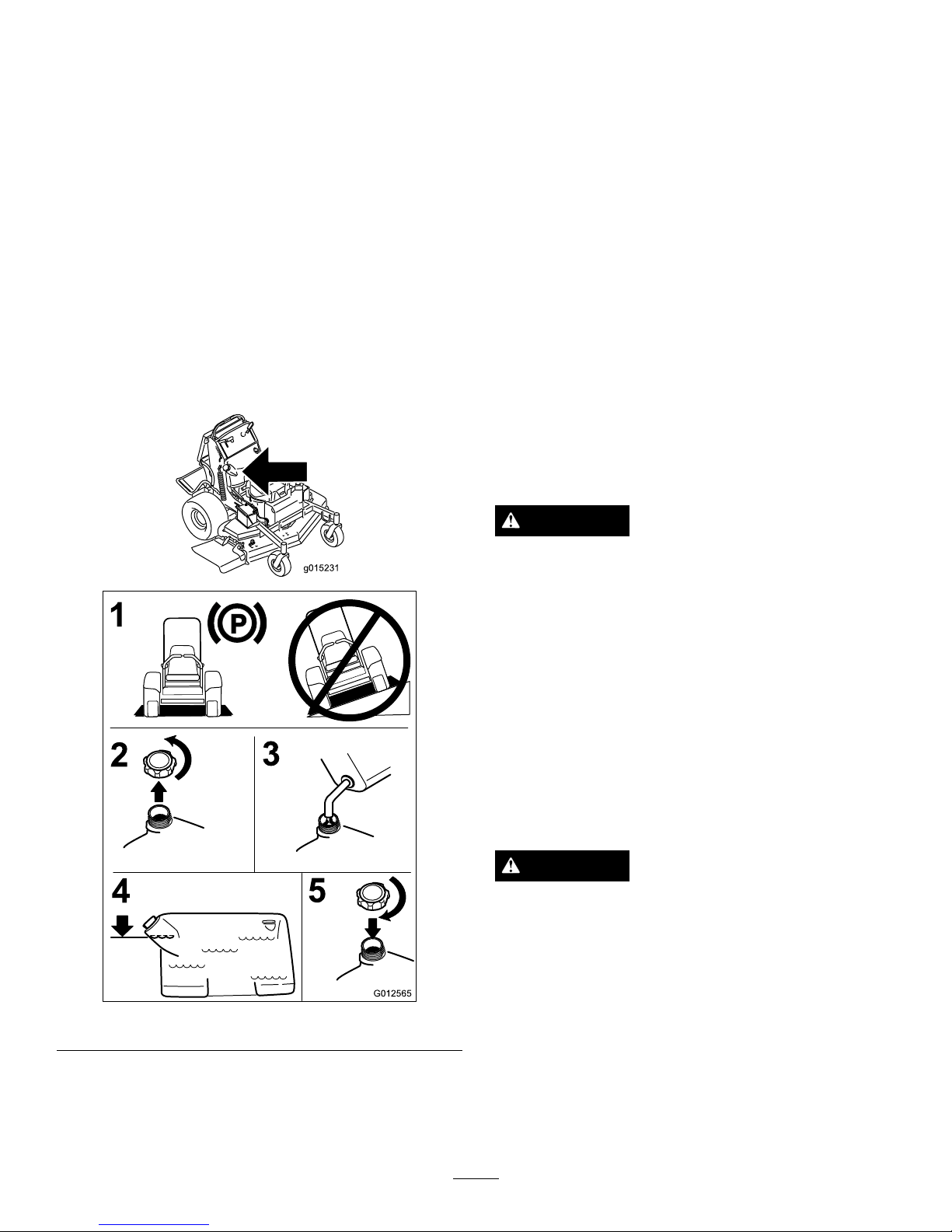
FillingtheFuelTank
Note:Donotllthefueltankcompletelyfull.Fillthe
fueltanktothebottomofthellerneck.Theempty
spaceinthetankallowsthegasolinetoexpand.
1.Parkthemachineonlevelground.
2.Shuttheengineoffandsettheparkingbrake.
3.Cleanaroundthefueltankcap.
4.Fillthefueltanktothebottomofthellerneck.
Ensurethereisemptyspaceinthetanktoallowthe
gasolinetoexpand
Figure7.
g015231
2
4
3
G012565
1
5
Figure7
CheckingtheEngineOilLevel
Beforeyoustarttheengineandusethemachine,check
theoillevelintheenginecrankcase;refertoChecking
OilLevelinEngineMaintenance.
BreakingInaNewMachine
Newenginestaketimetodevelopfullpower.Mower
decksanddrivesystemshavehigherfrictionwhennew,
placingadditionalloadontheengine.Allow40to50
hoursofbreak-intimefornewmachinestodevelopfull
powerandbestperformance.
ThinkSafetyFirst
Carefullyreadallthesafetyinstructionsanddecalsin
thesafetysection.Knowingthisinformationcould
helpyouoranybystandersavoidinjury.
Theuseofprotectiveequipmentforeyes,hearing,feet
andheadisrecommended.
CAUTION
Thismachineproducessoundlevelsinexcessof
85dBAattheoperator'searandcancausehearing
lossthroughextendedperiodsofexposure.
Wearhearingprotectionwhenoperatingthis
machine.
OperatingtheParkingBrake
Alwayssettheparkingbrakewhenyoustopthe
machineorleaveitunattended.Beforeeachuse,check
theparkingbrakeforproperoperation.
Iftheparkingbrakedoesnotholdsecurely,adjustit.
RefertoServicingtheParkingBrake.
CAUTION
Childrenorbystandersmaybeinjuredifthey
moveorattempttooperatethemachinewhileit
isunattended.
Alwaysremovetheignitionkeyandsettheparking
brakewhenleavingthemachineunattended,even
ifjustforafewminutes.
SettingtheParkingBrake
Pulltheparkingbrakeleverrearwardandoverinto
engagedposition(
Figure8).
16
Page 17
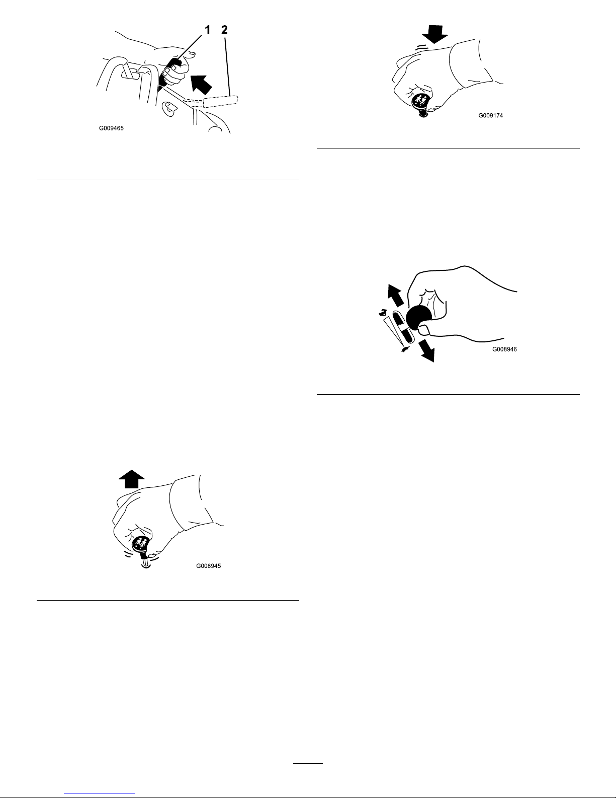
Figure8
1.Parkingbrakeengaged2.Parkingbrakereleased
ReleasingtheParkingBrake
Pullthebrakeleverbackandoverintotheslotand
pushtheparkingbrakeleverforward.
OperatingtheMowerBlade
ControlSwitch(PTO)
Thebladecontrolswitch(PTO)isusedinconjunction
withtherightsidemotioncontrollevertoengageand
disengagethemowerblades.
EngagingtheMowerBlades(PTO)
1.Toengagethemowerblades,movetherightside
motioncontrollevertothecenter,un-locked
position.
2.Pullthebladecontrolswitch(PTO)upandrelease
itwhileholdingdowntherightsidemotioncontrol
leverinthecenter,un-lockedposition.
G008945
Figure9
DisengagingtheMowerBlades(PTO)
Thefollowingaretwooptionsfordisengagingthe
mowerblades.
•Pushthebladecontrolswitch(PTO)downtothe
offposition.
•Movethemotioncontrolleverstoneutralandmove
therightsidemotioncontrolleverintotheneutral
lockposition.
G009174
Figure10
OperatingtheThrottle
ThethrottlecontrolcanbemovedbetweenFastand
Slowpositions(Figure11).
Alwaysusethefastpositionwhenturningonthe
mowerdeckwiththebladecontrolswitch(PTO).
G008946
Figure11
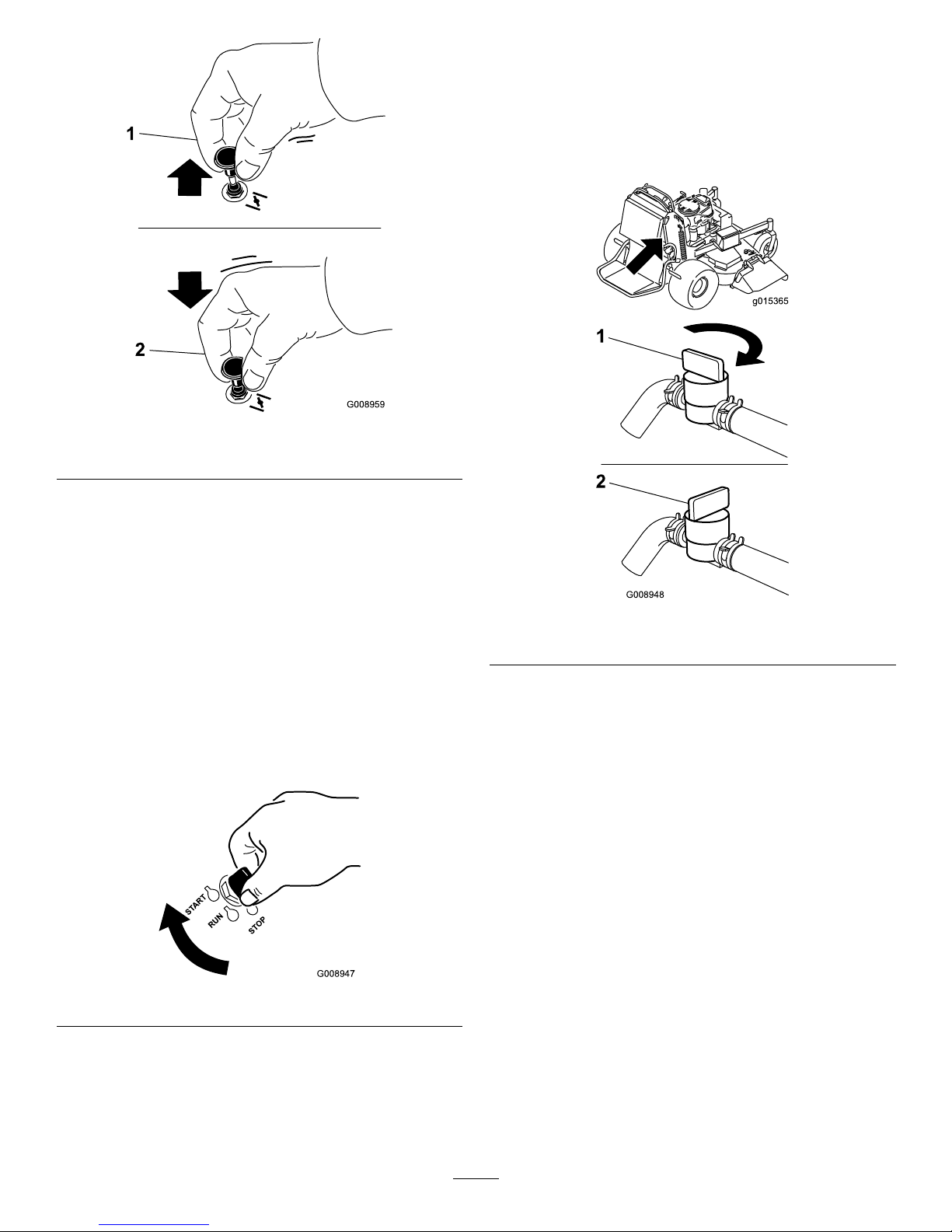
OperatingtheChoke
Usethechoketostartacoldengine.
1.Iftheengineiscold,usethechoketostartthe
engine.
2.Pulluponthechokeknobtoengagethechoke
beforeusingtheignitionswitch(
Figure12).
3.Pushdownonthechoketodisengagethechoke
aftertheenginehasstarted(Figure12).
17
Page 18
G008959
1
2
Figure12
1.On2.Off
OperatingtheIgnitionSwitch
1.TurntheignitionkeytotheStartposition
(Figure13).Whentheenginesstarts,releasethekey.
Important:Donotengagestarterformore
than5secondsatatime.Iftheenginefails
tostartallowa15secondcool-downperiod
betweenattempts.Failuretofollowthese
instructionscanburnoutthestartermotor.
Note:Additionalstartingcyclesmayberequired
whenstartingtheengineforthersttimeafterthe
fuelsystemhasbeenwithoutfuelcompletely .
START
RUN
STOP
G008947
Figure13
2.Turntheignitionkeytostoptostoptheengine.
UsingtheFuelShut-OffValve
Closethefuelshut-offvalvefortransport,maintenance,
andstorage(Figure14).
Ensurethefuelshut-offvalveisopenwhenstarting
theengine.
g015365
G008948
1
2
Figure14
1.On2.Off
StartingandStoppingthe
Engine
StartingtheEngine
1.Connectthewirestothesparkplugs.
2.Openthefuelvalve.
3.Movetherightmotioncontrollevertoneutral
lockedposition.
4.Settheparkingbrake;refertoSettingtheParking
Brake.
5.Movethebladecontrolswitch(PTO)totheOff
position.
6.MovethethrottlelevermidwaybetweentheSlow
andFastpositions.
Note:Awarmorhotenginemaynotrequire
choking.
18
Page 19
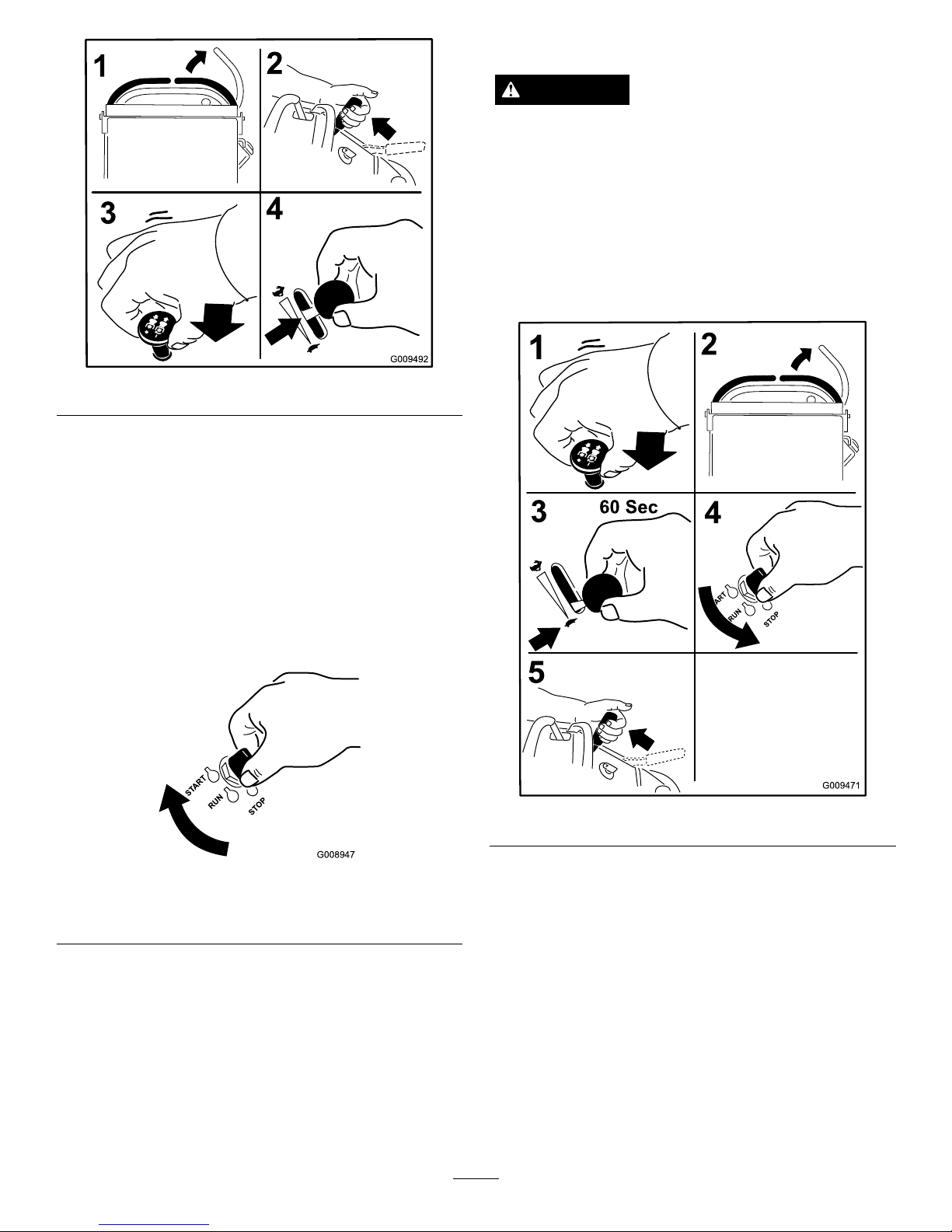
Figure15
7.TurntheignitionkeytotheStartposition
(Figure13).Whentheenginesstarts,releasethekey.
Important:Donotengagestarterformore
than5secondsatatime.Iftheenginefails
tostartallowa15secondcool-downperiod
betweenattempts.Failuretofollowthese
instructionscanburnoutthestartermotor.
Note:Additionalstartingcyclesmayberequired
whenstartingtheengineforthersttimeafterthe
fuelsystemhasbeenwithoutfuelcompletely .
START
RUN
STOP
G008947
Figure16
1.Off3.Start
2.Run
StoppingtheEngine
CAUTION
Childrenorbystandersmaybeinjuredifthey
moveorattempttooperatethetractorwhileitis
unattended.
Alwaysremovetheignitionkeyandsettheparking
brakewhenleavingthemachineunattended,even
ifjustforafewminutes.
Lettheengineidleatslowthrottle(turtle)for60
secondsbeforeturningtheignitionswitchoff.
Figure17
Important:Makesurefuelshutoffvalveisclosed
beforetransportingorstoringthemachine,asfuel
leakagemayoccur.Beforestoringthemachine,
pullwireoffsparkplug(s)topreventpossibilityof
accidentalstarting.
19
Page 20
TheSafetyInterlockSystem
CAUTION
Ifsafetyinterlockswitchesaredisconnectedor
damagedthemachinecouldoperateunexpectedly
causingpersonalinjury.
•Donottamperwiththeinterlockswitches.
•Checktheoperationoftheinterlockswitches
dailyandreplaceanydamagedswitchesbefore
operatingthemachine.
UnderstandingtheSafetyInterlock
System
Thesafetyinterlocksystemisdesignedtopreventthe
mowerbladesfromrotatingunless:
•Therightsidemotioncontrolleverismovedtothe
center,un-lockedposition.
•Thebladecontrolswitch(PTO)ispulledon.
Thesafetyinterlocksystemisdesignedtostopthe
mowerbladesifyoumoveorreleasetherightside
motioncontrolleverintotheneutrallockposition.
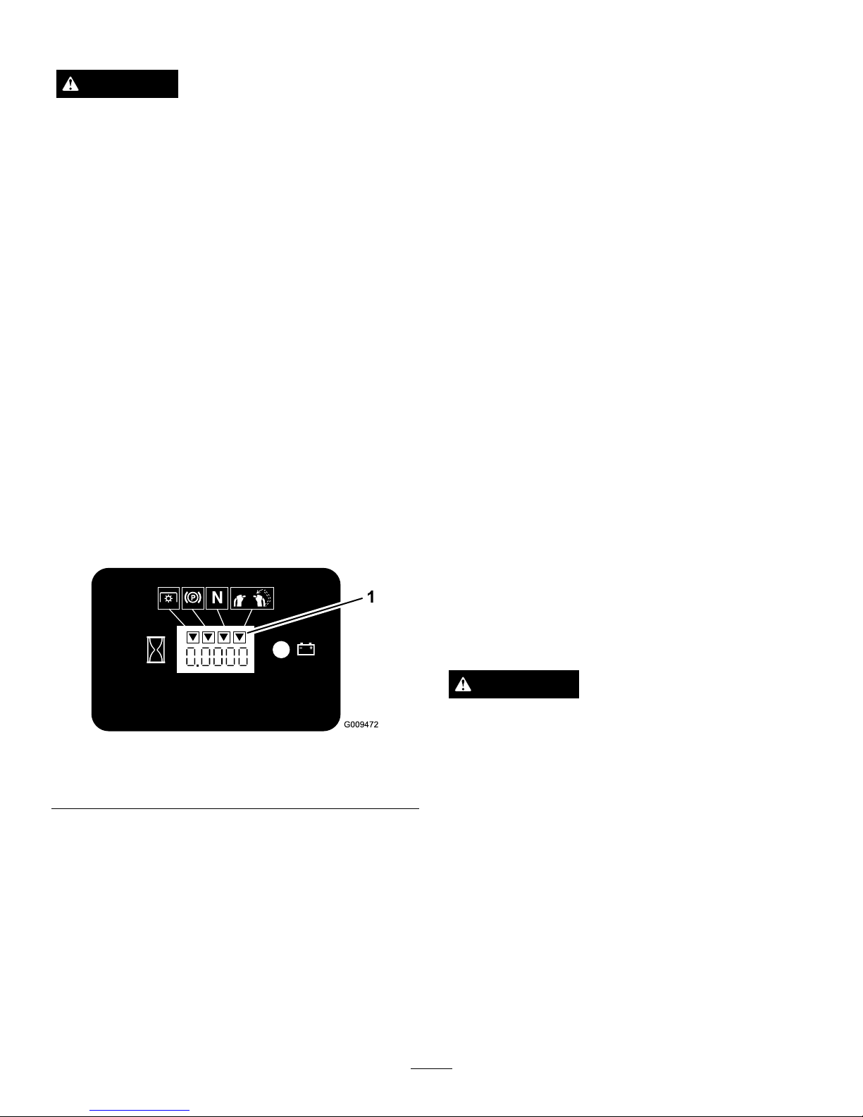
Thehourmeterhassymbolstonotifytheuserwhen
theinterlockcomponentisinthecorrectposition.
Whenthecomponentisinthecorrectposition,a
trianglewilllightupinthecorrespondingsquare.
Figure18
1.Triangleslightupwhentheinterlockcomponentsareinthe
correctposition
TestingtheSafetyInterlockSystem
ServiceInterval:Beforeeachuseordaily
Testthesafetyinterlocksystembeforeyouusethe
machineeachtime.
Note:Ifthesafetysystemdoesnotoperateas
describedbelow,haveanAuthorizedServiceDealer
repairthesafetysystemimmediately .
1.Starttheengine;refertoStartingandStoppingthe
Engine.
2.Settheparkingbrake.
3.Movetherightsidemotioncontrollevertothe
center,un-lockedposition.Thebladesshould
notrotate.
4.Movethemotioncontrolleversforward.The
engineshouldkill.
5.Starttheengineandreleasetheparkingbrake.
6.Movetherightsidemotioncontrollevertothe
center,un-lockedposition.
7.Continueholdingtherightsidemotioncontrollever
inthecenter,un-lockedpositionandpulluponthe
bladecontrolswitch(PTO)andrelease.Theclutch
shouldengageandthemowerbladesbeginrotating.
8.Moveorreleasetherightsidemotioncontrollever
intotheneutrallockposition.Thebladesshould
stoprotatingandtheenginecontinuestorun.
9.Pushthebladecontrolswitchdownandmove
therightsidemotioncontrollevertothecenter,
un-lockedposition.
10.Continueholdingtherightsidemotioncontrollever
inthecenter,un-lockedpositionandpulluponthe
bladecontrolswitch(PTO)andrelease.Theclutch
shouldengageandthemowerbladesbeginrotating.
11.Pushthebladecontrolswitch(PTO)downtothe
offposition.Thebladesshouldstoprotating.
12.Withtheenginerunning,pullupthebladecontrol
switch(PTO)andreleasewithoutholdingright
sidemotioncontrollevertothecenter,un-locked
position.Thebladesshouldnotrotate.
WARNING
Theoperatorplatformisheavyandmaycause
injurywhenloweringandraisingtheoperator
platform.Theplatformmaysuddenlydropifnot
supportedwhenthelatchpinispulledout.
•Donotputhandsorngersintheplatform
pivotareawhenloweringorraisingtheoperator
platform.
•Makesuretheplatformissupportedwhenthe
latchpinispulledout.
•Makesurethelatchsecurestheplatformwhen
foldingitintheupposition.Pushittight
againstthecushionforthelatchpintolock
intoplace.
•Keepbystandersawaywhenraisingorlowering
theplatform.
20
Page 21
OperatingthePlatform
Themachinecanbeusedwiththeplatformintheup
ordownposition.Itistheoperator'spreferenceon
whichpositiontouse.
OperatingtheMachinewiththe
PlatformUp
Operatingthemachinewiththeplatformupis
recommendedwhen:
•Mowingneardrop-off's
•Mowingsmallareaswherethemachineistoolong
•Areaswithlowoverhangingbranchesorobstacles
•Loadingthemachinefortransport
•Drivingupslopes
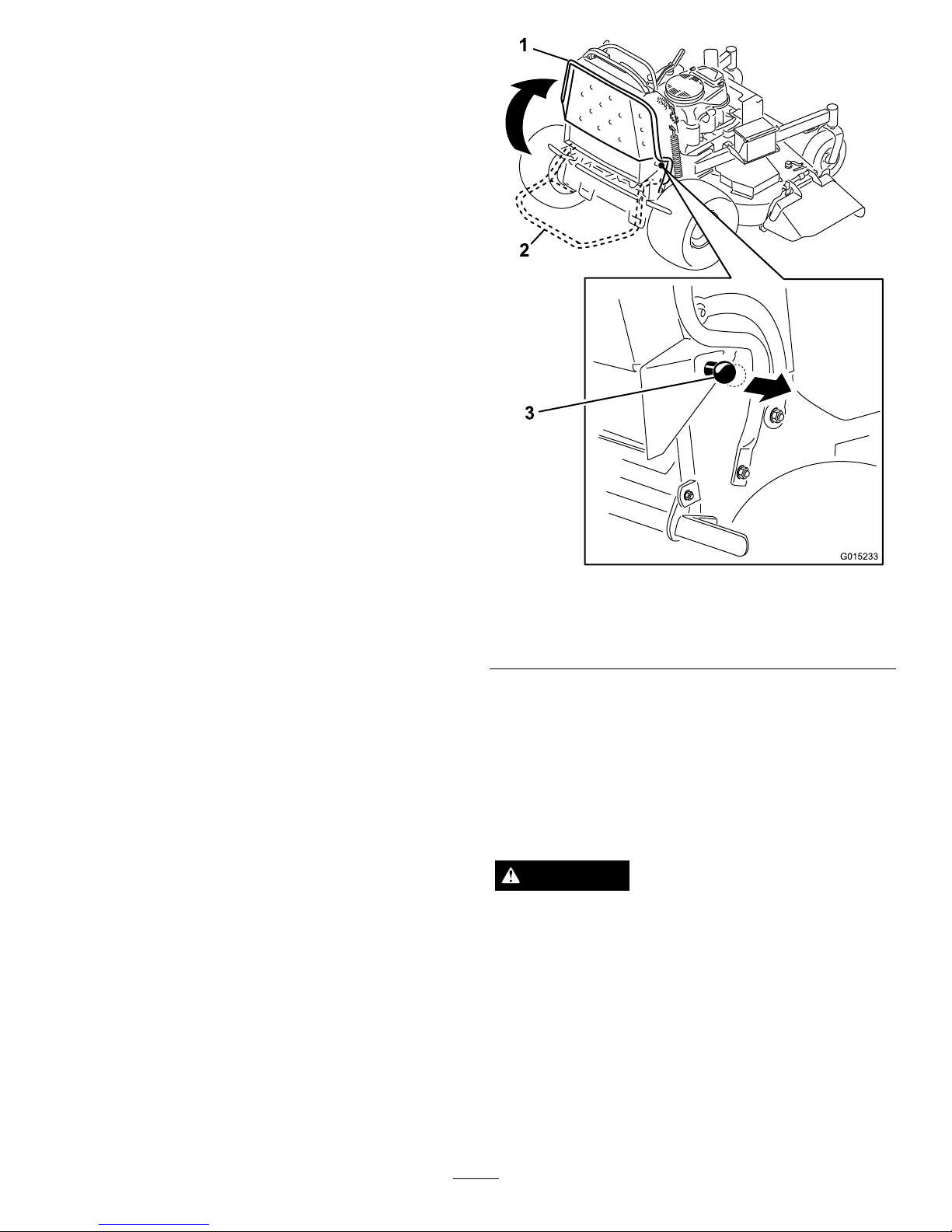
Toraisetheplatform,pullthebackoftheplatformup
sothelatchpinandknoblockitintoplace.Pushittight
againstthecushionforthelatchpintolockintoplace.
OperatingtheMachinewiththe
PlatformDown
Operatingthemachinewiththeplatformdownis
recommendedwhen:
•Mowingmostareas
•Drivingacrossslopes
•Drivingdownslopes
Tolowertheplatform,pushtheplatformforward
againstthecushiontoreleasepressureonthelatchpin
andthenpulltheknoboutandlowertheplatform.
G015233
Figure19
1.Platformup
3.Pulltheknobouttorelease
theplatform
2.Platformdown
DrivingForwardorBackward
Thethrottlecontrolregulatestheenginespeedas
measuredinrpm(revolutionsperminute).Place
thethrottlecontrolinthefastpositionforbest
performance.Alwaysoperateinthefullthrottle
positionwhenmowing.
CAUTION
Machinecanspinveryrapidly.Operatormaylose
controlofmachineandcausepersonalinjuryor
damagetomachine.
Slowthemachinedownbeforemakingsharpturns.
DrivingForward
1.Releasetheparkingbrake;refertoReleasingthe
ParkingBrakeinOperation.
2.Movetherightsidemotioncontrollevertothe
center,un-lockedposition.
21
Page 22

G015234
4
5
1
2
3
3 4
Figure20
1.Frontreferencebar
4.Rightcontrollever
2.Leftcontrollever
5.Rightcontrolleverinthe
neutrallockposition
3.Rearreferencebar
3.Togoforward,movethespeedcontrollevertothe
desiredspeed.
4.Slowlypushthemotioncontrolleversforward
(
Figure21).
Note:Theenginewillkillifamotioncontrollever
ismovedwiththeparkingbrakeengaged.
Thefartheryoumovethemotioncontrolleversin
eitherdirection,thefasterthemachinewillmovein
thatdirection.
Tostop,pullthemotioncontrolleversbacktothe
neutralposition.
Figure21
DrivingBackward
1.Movetherightsidemotioncontrollevertothe
center,un-lockedposition.
2.Slowlypullthemotioncontrolleversrearward
(
Figure22).
Figure22
StoppingtheMachine
Tostopthemachine,movethemotioncontrolleversto
neutral,movetherightsidemotioncontrolleverinto
theneutrallockposition,disengagethepowertakeoff
(PTO),andturntheignitionkeytooff.
22
Page 23

Settheparkingbrakewhenyouleavethemachine;refer
toSettingtheParkingBrakeinOperation.Remember
toremovethekeyfromtheignitionswitch.
CAUTION
Childrenorbystandersmaybeinjuredifthey
moveorattempttooperatethetractorwhileitis
unattended.
Alwaysremovetheignitionkeyandsettheparking
brakewhenleavingthemachineunattended,even
ifjustforafewminutes.
UsingtheRotationIndicator
Theslotsinthetopofthebeltcoversallowthe
operatortoverifyifthebladeshavestoppedrotating
afterdisengagingthepowertake-off(PTO)switch.
Disengagethepowertake-off(PTO)switch,stopthe
engine,removethekey ,andwaitforallmovingpartsto
stopbeforeleavingtheoperatingposition.
G015493
1
1 2
1
Figure23
52inchmowerdeckshown
1.RotationIndicator-slotsin
thetopofthebeltcover
2.Sidedischargechute
PushingtheMachinebyHand
Theby-passvalvesallowthemachinetobepushedby
handwithouttheenginerunning.
Important:Alwayspushthemachinebyhand.
Nevertowthemachinebecausehydraulicdamage
mayoccur.
ToPushtheMachine
1.DisengagethePTO,movethemotioncontrollevers
totheneutrallockedpositionandsettheparking
brake.
2.Opentheby-passvalveonbothpumpsbyturning
themcounterclockwise1to2turns.Thisallows
hydraulicuidtoby-passthepumpsandthewheels
toturn(
Figure24).
Note:Rotatetheby-passvalvesamaximumof2
turnssothevalvedoesnotcomeoutofthebody
causinguidtorunout.
Figure24
1.Pumpby-passvalve
3.Releasetheparkingbrake.
4.Pushthemachinetothedesiredlocation.
5.Settheparkingbrake.
6.Closetheby-passvalves,butdonotovertighten
them.Torqueto110to130in-lb(12to15N-m).
Important:Donotstartoroperatethemachine
withtheby-passvalvesopen.Damageto
systemmayoccur.
TransportingMachines
Useaheavy-dutytrailerortrucktotransportthe
machine.Ensurethatthetrailerortruckhasall
necessarybrakes,lighting,andmarkingasrequiredby
law .Pleasecarefullyreadallthesafetyinstructions.
Knowingthisinformationcouldhelpyou,yourfamily,
petsorbystandersavoidinjury.
Totransportthemachine:
1.Raisetheplatformofthemachinebeforedrivingup
ontothetrailerortruck.
23
Page 24

2.Ifusingatrailer,connectittothetowingvehicle
andconnectthesafetychains.
3.Ifapplicable,connectthetrailerbrakes.
4.Loadthemachineontothetrailerortruck.
5.Stoptheengine,removethekey,setthebrake,and
closethefuelvalve.
6.Usethemetaltiedownloopsonthemachineto
securelyfastenthemachinetothetrailerortruck
withstraps,chains,cable,orropes(
Figure25).
G015235
Figure25
1.Tractionunittiedownloop
LoadingMachines
Useextremecautionwhenloadingunitsontrailersor
trucks.Onefullwidthrampthatiswideenoughto
extendbeyondthereartiresisrecommendedinsteadof
individualrampsforeachsideoftheunit(Figure26).
Theplatformwhendownandlockedintoposition,
extendsbackbetweentherearwheelsandservesasa
stopfortippingbackward.Havingafullwidthramp
providesasurfacefortheplatformtocontactifthe
unitstartstotipbackward.Withtheplatformup,afull
widthrampprovidesasurfacetowalkonbehindthe
unit.Theoperatorshoulddetermineifitisbesttohave
theplatformupordownwhenloading,dependingon
conditions.Ifitisnotpossibletouseonefullwidth
ramp,useenoughindividualrampstosimulateafull
widthcontinuousramp.
Therampshouldbelongenoughsothattheangles
donotexceed20degrees(
Figure26).Asteeperangle
maycausemowercomponentstogetcaughtastheunit
movesfromramptotrailerortruck.Steeperangles
mayalsocausetheunittotipbackward.Ifloadingon
ornearaslope,positionthetrailerortrucksoitison
thedownsideoftheslopeandtherampextendsupthe
slope.Thiswillminimizetherampangle.Thetraileror
truckshouldbeaslevelaspossible.
Important:DoNotattempttoturntheunitwhile
ontheramp;youmaylosecontrolanddriveoff
theside.
Avoidsuddenaccelerationwhendrivinguparampand
suddendecelerationwhenbackingdownaramp.Both
maneuverscancausetheunittotipbackward.
WARNING
Loadingaunitontoatrailerortruckincreasesthe
possibilityofbackwardtip-overandcouldcause
seriousinjuryordeath.
•Useextremecautionwhenoperatingauniton
aramp.
•Useonlyasingle,fullwidthramp;DoNotuse
individualrampsforeachsideoftheunit.
•Ifindividualrampsmustbeused,useenough
rampstocreateanunbrokenrampsurface
widerthantheunit.
•Donotexceeda20degreeanglebetweenramp
andgroundorbetweenrampandtraileror
truck.
•Avoidsuddenaccelerationwhiledrivingunitup
aramptoavoidtippingbackward.
•Avoidsuddendecelerationwhilebackingunit
downaramptoavoidtippingbackward.
Figure26
1.Trailer3.Notgreaterthan
20degrees
2.Fullwidthramp4.Fullwidthramp—sideview
24
Page 25

SideDischargingorMulching
theGrass
Thismowerhasahingedgrassdeectorthatdisperses
clippingstothesideanddowntowardtheturf.
DANGER
Withoutthegrassdeector,dischargecover,or
completegrasscatcherassemblymountedin
place,youandothersareexposedtobladecontact
andthrowndebris.Contactwithrotatingmower
blade(s)andthrowndebriswillcauseinjuryor
death.
•Neverremovethegrassdeectorfromthe
mowerbecausethegrassdeectorroutes
materialdowntowardtheturf.Ifthe
grassdeectoriseverdamaged,replaceit
immediately.
•Neverputyourhandsorfeetunderthemower.
•Nevertrytocleardischargeareaormower
bladesunlessyoureleasethebailandthepower
takeoff(PTO)isoff.Rotatetheignitionkeyto
Off.Alsoremovethekeyandpullthewire(s)
offthesparkplug(s).
AdjustingtheHeight-of-Cut
Theheight-of-cutcanbeadjustedfrom1to5inches
(25to127mm)in1/4inch(6mm)increments.
1.Movetheheight-of-cutlevertothetransport
position(allthewayup).
2.Selectaholeintheheight-of-cutbracket
correspondingtotheheight-of-cutdesiredand,
insertthepin(
Figure27).
3.Lowertheheight-of-cutlevertothepin(Figure27).
Figure27
1.Height-of-cutholes3.Height-of-cutlever
2.Height-of-cutpin
AdjustingtheFlowBafe
Themowerdischargeowcanbeadjustedfordifferent
typesofmowingconditions.Positionthecamlockand
bafetogivethebestqualityofcut.
1.DisengagethePTO,movethemotioncontrollevers
totheneutrallockedpositionandsettheparking
brake.
2.Stoptheengine,removethekey ,andwaitforall
movingpartstostopbeforeleavingtheoperating
position.
3.Toadjustthebafe,loosenthenut(
Figure28).
4.Adjustthebafeandnutintheslottothedesired
dischargeowandtightenthenut.
g012676
1 2
Figure28
1.Slot
2.Nut
25
Page 26

PositioningtheFlowBafe
Thefollowingguresareonlyrecommendationsfor
use.Adjustmentswillvarybygrasstype,moisture
content,andheightofgrass.
Note:Iftheenginepowerdrawsdownandthemower
groundspeedisthesame,openupthebafe.
PositionA
Thisisthefullrearposition(seeFigure29).The
suggesteduseforthispositionisafollows.
•Useforshort,lightgrassmowingconditions.
•Useindryconditions.
•Forsmallergrassclippings.
•Propelsgrassclippingsfartherawayfromthe
mower.
G012677
Figure29
PositionB
Usethispositionwhenbagging(Figure30).
G012678
Figure30
PositionC
Thisisthefullopenposition.Thesuggestedusefor
thispositionisasfollows(Figure31).
•Useintall,densegrassmowingconditions.
•Useinwetconditions.
•Lowerstheenginepowerconsumption.
•Allowsincreasedgroundspeedinheavyconditions.
G012679
Figure31
UsingtheMid-SizeWeight
•Weightsareinstalledtoimprovehandling,balance
andimproveperformance.Weightscanbeaddedor
removedtocreateoptimizedperformanceunder
differentmowingconditionsandforoperator
preference.
•Itisrecommendedthatweightsbeaddedor
removedoneatatimeuntilthedesiredhandingand
balanceisachieved.
26
Page 27

Note:ContactanAuthorizedServiceDealertoorder
aW eightKit.
WARNING
Excessiveweightchangescaneffecthandlingand
operationofthemachine.Thiscouldcauseserious
injurytoyouorbystanders.
Makeweightchangesissmallincrementsonly.
Evaluatethemoweraftereachweightchangeto
ensurethemachinecanbeoperatedsafely.
27
Page 28

Maintenance
Note:Determinetheleftandrightsidesofthemachinefromthenormaloperatingposition.
RecommendedMaintenanceSchedule(s)
MaintenanceService
Interval
MaintenanceProcedure
Aftertherst8hours
•Changetheengineoil.
•Checkthehydraulicuidlevel.
•Changethehydrauliclter.
Beforeeachuseordaily
•Checkthesafetyinterlocksystem.
•Checktheengineoillevel.
•Cleantheairintakescreen.
•Checkthebrakes.
•Inspecttheblades.
•Cleanthemowerdeck.
Every25hours
•Cleanfoamaircleanerelement.
Every50hours
•Greasetheliftlinkage(moreoftenindirtyordustyconditions).
•Greasethemowerdeckspindles(moreoftenindirtyordustyconditions).
•Checkthepaperaircleanerelement.
•Checkthetirepressure.
•Checkthehydraulicuidlevel.
Every100hours
•Changetheengineoil.(moreoftenindirtyordustyconditions)
•Check,cleanandregapthesparkplug.
•Checkthebattery.
•Checktheelectricclutch.
•Checkandcleanenginecoolingnsandshrouds.
•Checkthemowerdeckbelt.
•Checkthepumpdrivebelt.
•Checkthehydraulichoses.
Every200hours
•Replacethepaperaircleanerelement.
•Changetheengineoillter.
Every250hours
•ChangethehydrauliclterandhydraulicoilwhenusingMobil®1oil.
Every500hours
•Adjustthecasterpivotbearing.
•ChangethehydrauliclterandhydraulicoilwhenusingT oro®HYPR-OIL™500
hydraulicoil.
Beforestorage
•Paintchippedsurfaces.
•Performallmaintenanceprocedureslistedabovebeforestorage.
Yearly
•Greasethefrontcasterpivots(moreoftenindirtyordustyconditions).
•Lubricatethecasterwheelhubs
•Replacethefuellter.
Important:Refertoyour
Engine Operator's Man ual
foradditionalmaintenanceprocedures.
CAUTION
Ifyouleavethekeyintheignitionswitch,someonecouldaccidentlystarttheengineandseriouslyinjure
youorotherbystanders.
Removethekeyfromtheignitionanddisconnectthesparkplugwiresfromthesparkplugsbeforeyoudo
anymaintenance.Setthewiresasidesothattheydonotaccidentallycontactthesparkplugs.
28
Page 29

Premaintenance
Procedures
RaisingtheMowerforAccess
Thefrontofthemowercanberaisedandsupportedon
itsbackforaccessunderthemachineformaintenance.
1.Raisetheplatform.RefertoOperatingthePlatform
inOperation.
2.Removethebattery.
Figure32
1.Wingnut4.Positivebatterycable
2.Batterycover5.Battery
3.Negativebatterycable
3.Drainthefuelfromthefueltank.RefertoDraining
theFuelTankinMaintenance.
4.Removethecapofthehydraulictankandplace
apieceofplasticovertheopeningandinstallthe
hydrauliccap.Thiswillsealthehydraulictankand
preventitfromleakingout.
g015408
1
2
3
Figure33
1.Cap
3.Hydraulictank
2.Pieceofplastic
5.Withtwopeople,raisethefrontofthemowersoit
restsonthedrivetiresandtheplatformintheup
position.
6.Performanymaintenanceonthemachine.
7.Withtwopeople,lowerthefrontofthemowerto
theground.
8.Removetheplasticunderthehydraulictankcap.
9.Installthebatteryforthemachine.
29
Page 30

Figure34
1.Removebattery
2.Withtwopeople,liftthe
frontendofthemower
(ensuretheplatformisup)
ReleasetheCushionforRear
Access
Thecushioncanbereleasedforrearaccesstothe
machineformaintenanceoradjustment.
1.Lowertheplatform.
2.Removethehairpincotterpinsoneachsideofthe
cushion.
3.Slidethelargewasherswithplasticbushingstothe
inside.
4.Removethecushionandlowerittotheplatform.
5.Performanymaintenanceoradjustmentonthe
machine.
6.Raisethecushionandslideitontothepinsonboth
sidesofthemachine(
Figure35).
7.Slidethelargewashersplasticbushingsintothe
cushionbracketandsecurethemwithahairpin
cotterpin(Figure35).
Figure35
1.Plasticbushingwithlarge
washer
3.Hairpincotterpin
2.Cushionbracketwithkey
hole
30
Page 31

Lubrication
GreasewithNo.2generalpurposelithiumbaseor
molybdenumbasegrease.
HowtoGrease
1.DisengagethePTOandsettheparkingbrake.
2.Stoptheengine,removethekey ,andwaitforall
movingpartstostopbeforeleavingtheoperating
position.
3.Cleanthegreasettingswitharag.Makesureto
scrapeanypaintoffthefrontofthetting(s).
4.Connectagreaseguntothetting.Pumpgrease
intothettingsuntilgreasebeginstooozeoutof
thebearings.
5.Wipeupanyexcessgrease.
LubricatingtheMachine
ServiceInterval:Every50hours—Greasethelift
linkage(moreoftenindirtyordusty
conditions).
Every50hours—Greasethemower
deckspindles(moreoftenindirtyor
dustyconditions).
Usethefollowinggraphicsforlocatingthegreasepoints.
Figure36
G015236
Figure37
g015589
Figure38
GreasingtheFrontCaster
Pivots
ServiceInterval:Yearly
Lubricatethefrontcasterpivotsonceayear.
1.Removethedustcapandadjustthecasterpivots.
Keepthedustcapoffuntilgreasingisdone.Referto
AdjustingtheCasterPivotBearinginMaintenance
Section.
2.Removethehexplug.Threadagreasezerkintothe
hole.
3.Pumpgreaseintothezerkuntilitoozesoutaround
thetopbearing.
4.Removethegreasezerkinthehole.Installthehex
plugandcap.
31
Page 32

LubricateCasterWheelHubs
ServiceInterval:Yearly
1.Stoptheengine,waitforallmovingpartstostop,
andremovethekey.Engagetheparkingbrake.
Figure39
1.Sealguard2.Spacernutwithwrench
ats
2.Removethecasterwheelfromthecasterforks.
3.Removethesealguardsfromthewheelhub.
4.Removeoneofthespacernutsfromtheaxle
assemblyinthecasterwheel.Notethatthread
lockingadhesivehasbeenappliedtolockthespacer
nutstotheaxle.Removetheaxle(withtheother
spacernutstillassembledtoit)fromthewheel
assembly.
5.Pryoutseals,andinspectbearingsforwearor
damageandreplaceifnecessary.
6.Packthebearingswithageneral-purposegrease.
7.Insertonebearing,onenewsealintothewheel.
Note:Thesealsmustbereplaced.
8.Iftheaxleassemblyhashadbothspacernuts
removed(orbrokenloose),applyathreadlocking
adhesivetoonespacernutandthreadontotheaxle
withthewrenchatsfacingoutward.DoNotthread
spacernutallofthewayontotheendoftheaxle.
Leaveapproximately1/8inch(3mm)fromtheouter
surfaceofthespacernuttotheendoftheaxleinside
thenut.
9.Inserttheassemblednutandaxleintothewheelon
thesideofthewheelwiththenewsealandbearing.
10.Withtheopenendofthewheelfacingup,ll
theareainsidethewheelaroundtheaxlefullof
general-purposegrease.
11.Insertthesecondbearingandnewsealintothe
wheel.
12.Applyathreadlockingadhesivetothe2ndspacer
nutandthreadontotheaxlewiththewrenchats
facingoutward.
13.Torquethenutto75-80in-lb(8-9N-m),loosen,
thenre-torqueto20-25in-lb(2-3N-m).Makesure
axledoesnotextendbeyondeithernut.
14.Reinstallthesealguardsoverthewheelhuband
insertwheelintocasterfork.Reinstallcasterbolt
andtightennutfully .
Important:Topreventsealandbearingdamage,
checkthebearingadjustmentoften.Spinthecaster
tire.Thetireshouldnotspinfreely(morethan1or
2revolutions)orhaveanysideplay .Ifthewheel
spinsfreely,adjusttorqueonspacernutuntilthere
isaslightamountofdrag.Reapplythreadlocking
adhesive.
32
Page 33

EngineMaintenance
ServicingtheAirCleaner
ServiceInterval/Specication
Inspectthefoamandpaperelementsandreplacethem
iftheyaredamagedorexcessivelydirty.
Note:Servicetheaircleanermorefrequently(every
fewoperatinghours)iftheoperatingconditionsare
extremelydustyorsandy .
Important:Donotoilthefoamorpaperelement.
RemovingtheFoamandPaper
Elements
1.DisengagethePTOandsettheparkingbrake.
2.Stoptheengine,removethekey ,andwaitforall
movingpartstostopbeforeleavingtheoperating
position.
3.Cleanaroundtheaircleanertopreventdirt
fromgettingintotheengineandcausingdamage
(
Figure40).
4.Unscrewthecoverknobsandremovetheaircleaner
cover(Figure40).
5.Unscrewthehoseclampandremovetheaircleaner
assembly(
Figure40).
6.Carefullypullthefoamelementoffthepaper
element(Figure40).
Figure40
1.Cover
3.Paperelement
2.Hoseclamp4.Foamelement
CleaningtheFoamAirCleanerElement
ServiceInterval:Every25hours
1.Washthefoamelementinliquidsoapandwarm
water.Whentheelementisclean,rinseitthoroughly.
2.Drytheelementbysqueezingitinacleancloth.
Important:Replacethefoamelementifitis
tornorworn.
ServicingthePaperAirCleaner
Element
ServiceInterval:Every50hours—Checkthepaperair
cleanerelement.
Every200hours—Replacethepaper
aircleanerelement.
1.Donotcleanthepaperlter,replaceit(
Figure40).
2.Inspecttheelementfortears,anoilylm,ordamage
totherubberseal.
3.Replacethepaperelementifitisdamaged.
InstallingtheFoamandPaperElements
Important:Topreventenginedamage,always
operatetheenginewiththecompletefoamand
paperaircleanerassemblyinstalled.
1.Carefullyslidethefoamelementontothepaperair
cleanerelement(
Figure40).
2.Placetheaircleanerassemblyontotheaircleaner
baseorhoseandsecureit(
Figure40).
3.Placetheaircleanercoverintopositionandtighten
thecoverknob(Figure40).
ServicingtheEngineOil
ServiceInterval:Beforeeachuseordaily—Checkthe
engineoillevel.
Aftertherst8hours—Changethe
engineoil.
Every100hours—Changetheengine
oil.(moreoftenindirtyordusty
conditions)
Every200hours—Changetheengine
oillter.
Note:Changetheoilmorefrequentlywhenthe
operatingconditionsareextremelydustyorsandy.
33
Page 34

Note:Therearedifferentoilcapacitiesforthedifferent
modelslistedinthismanual.Ensurethecorrectamount
ofoilisused.
Important:Remembertoadd80%oftheoiland
thengraduallyllittothefullmarkonthedipstick.
OilType:Detergentoil(APIserviceSF ,SG,SH,SJ
orSL)
CrankcaseCapacity:58ounces(1.7liter)withthelter
removed;51ounces(1.5liter)withoutthelterremoved
Viscosity:Refertothetablebelow
Figure41
CheckingtheEngineOilLevel
Note:Checktheoilwhentheengineiscold.
WARNING
Contactwithhotsurfacesmaycausepersonal
injury.
Keephands,feet,face,clothingandotherbody
partsawaythemuferandotherhotsurfaces.
Important:Donotoverllthecrankcasewithoil
becausedamagetotheenginemayresult.Donot
runenginewithoilbelowthelowmarkbecausethe
enginemaybedamaged.
1.DisengagethePTO,movethemotioncontrollevers
totheneutrallockedpositionandsettheparking
brake.
2.Stoptheengine,removethekey ,andwaitforall
movingpartstostopbeforeleavingtheoperating
position(Figure42).
g015238
G008792
1
2
5
6
7
3
9
10
4
8
Figure42
ChangingtheEngineOil
Note:Disposeoftheusedoilatarecyclingcenter.
1.Parkthemachinesothatthedrainsideisslightly
lowerthantheoppositesidetoassuretheoildrains
completely.
2.DisengagethePTO,movethemotioncontrollevers
totheneutrallockedpositionandsettheparking
brake.
34
Page 35

3.Stoptheengine,removethekey ,andwaitforall
movingpartstostopbeforeleavingtheoperating
position(Figure43).
g015238
Figure43
4.Slowlypourapproximately80%ofthespeciedoil
intothellertubeandslowlyaddtheadditionaloil
tobringittotheFullmark(
Figure44).
G008796
2
3
4
5
6
1
Figure44
ChangingtheEngineOilFilter
Note:Changetheengineoilltermorefrequently
whenoperatingconditionsareextremelydustyorsandy.
1.Draintheoilfromtheengine;refertoChangingthe
EngineOil.
2.Placearagundertheoilltertosoakupanyspilled
oil.
Important:Spilledoilmaydrainunderthe
engineandontotheclutch.Oilspilledonthe
clutchmaydamagetheclutch,causetheblades
tostopslowlywhentheclutchisswitchedoff
andcausetheclutchtoslipwhentheclutchis
switchedon.Wipeupanyspilledoil.
3.Changetheengineoillter(
Figure45).
35
Page 36

g015238
G012845
3/4
2
3
4
5
6
1
Figure45
Note:Ensuretheoilltergaskettouchestheengine
andthenanextra3/4turniscompleted.
4.Fillthecrankcasewiththepropertypeofnewoil;
refertoChangingtheOil.
ServicingtheSparkPlug
ServiceInterval:Every100hours
Makesuretheairgapbetweenthecenterandside
electrodesiscorrectbeforeinstallingthesparkplug.
Useasparkplugwrenchforremovingandinstalling
thesparkplug(s)andagappingtool/feelergaugeto
checkandadjusttheairgap.Installanewsparkplug(s)
ifnecessary.
Type:NGK
®
BPR4ESorequivalent
AirGap:0.030inch(0.75mm)
RemovingtheSparkPlug
1.DisengagethePTO,movethemotioncontrollevers
totheneutrallockedpositionandsettheparking
brake.
2.Stoptheengine,removethekey ,andwaitforall
movingpartstostopbeforeleavingtheoperating
position.
g015238
Figure46
CheckingtheSparkPlug
Important:Nevercleanthesparkplug(s).Always
replacethesparkplug(s)whenithas:ablack
coating,wornelectrodes,anoilylm,orcracks.
Ifyouseelightbrownorgrayontheinsulator,the
engineisoperatingproperly.Ablackcoatingonthe
insulatorusuallymeanstheaircleanerisdirty.
Setthegapto0.030inches(0.75mm).
G008794
1
2
Figure47
36
Page 37

InstallingtheSparkPlug
Tightenthesparkplug(s)to16ft.-lb(22N-m).
3
2
1
G015200
Figure48
FuelSystem
Maintenance
DrainingtheFuelTank
Note:Thereisnootherrecommendedwaytodrain
fuelfromthetank,otherthanusingasyphonpump.A
syphonpumpcanbepurchasedatahardwarestore.
DANGER
Incertainconditions,gasolineisextremely
ammableandhighlyexplosive.Areorexplosion
fromgasolinecanburnyouandothersandcan
damageproperty.
•Draingasolinefromthefueltankwhenthe
engineiscold.Dothisoutdoorsinanopenarea.
Wipeupanygasolinethatspills.
•Neversmokewhendraininggasoline,andstay
awayfromanopenameorwhereasparkmay
ignitethegasolinefumes.
1.Parkthemachineonalevelsurface.Disengagethe
powertakeoff(PTO),settheparkingbrake,turnthe
ignitionkeytoOffandremovethekey .
2.Cleanaroundthefuelcaptopreventdebrisfrom
gettingintothefueltank(
Figure50).
3.Removethefuelcap.
4.Insertasyphonpumpintothefueltank.
5.Usingthesyphonpump,drainthefuelintoaclean
gascan(
Figure49).
6.Wipeupanyspilledfuel.
g015239
Figure49
1.Fuelcap
37
Page 38

ServicingtheFuelFilter
ReplacingtheFuelFilter
ServiceInterval:Yearly
Neverinstalladirtylterifitisremovedfromthefuel
line.
Note:Notehowthefuellterisinstalledinorderto
installthenewltercorrectly.
Note:Wipeupanyspilledfuel.
1.DisengagethePTOandsettheparkingbrake.
2.Stoptheengine,removethekey ,andwaitforall
movingpartstostopbeforeleavingtheoperating
position.
3.Closefuelshut-offvalve(behindtheoperator
cushion).
4.Squeezetheendsofthehoseclampstogetherand
slidethemawayfromthelter(
Figure50).
Figure50
1.Hoseclamp3.Filter
2.Fuelline
5.Removethelterfromthefuellines.
6.Installanewlterandmovethehoseclampsclose
tothelter.
7.Openthefuelshut-offvalve.
8.Checkforfuelleaksandrepairifneeded.
9.Wipeupanyspilledfuel.
ElectricalSystem
Maintenance
ServicingtheBattery
ServiceInterval:Every100hours
Alwayskeepthebatterycleanandfullycharged.Use
apapertoweltocleanthebatterycase.Ifthebattery
terminalsarecorroded,cleanthemwithasolutionof
fourpartswaterandonepartbakingsoda.Applyalight
coatingofgreasetothebatteryterminalstoprevent
corrosion.
Voltage:12V
WARNING
CALIFORNIA
Proposition65Warning
Batteryposts,terminals,andrelated
accessoriescontainleadandleadcompounds,
chemicalsknowntotheStateofCalifornia
tocausecancerandreproductiveharm.
Washhandsafterhandling.
DANGER
Batteryelectrolytecontainssulfuricacidwhichisa
deadlypoisonandcausessevereburns.
Donotdrinkelectrolyteandavoidcontactwith
skin,eyesorclothing.Wearsafetyglassestoshield
youreyesandrubberglovestoprotectyourhands.
RemovingtheBattery
WARNING
Batteryterminalsormetaltoolscouldshortagainst
metalmachinecomponentscausingsparks.Sparks
cancausethebatterygassestoexplode,resulting
inpersonalinjury.
•Whenremovingorinstallingthebattery ,donot
allowthebatteryterminalstotouchanymetal
partsofthemachine.
•Donotallowmetaltoolstoshortbetween
thebatteryterminalsandmetalpartsofthe
machine.
38
Page 39

WARNING
Incorrectbatterycableroutingcoulddamagethe
machineandcablescausingsparks.Sparkscan
causethebatterygassestoexplode,resultingin
personalinjury.
•AlwaysDisconnectthenegative(black)battery
cablebeforedisconnectingthepositive(red)
cable.
•AlwaysReconnectthepositive(red)battery
cablebeforereconnectingthenegative(black)
cable.
1.DisengagethePTOandsettheparkingbrake.
2.Stoptheengine,removethekey ,andwaitforall
movingpartstostopbeforeleavingtheoperating
position.
3.Lifttheblackrubbercoveronthenegativecable.
Disconnectthenegativebatterycablefromthe
negative(-)batteryterminal(
Figure51).
4.Slidetheredterminalbootoffthepositive(red)
batteryterminal.Thenremovethepositive(red)
batterycable(
Figure51).
5.Removethebatteryholddownplate(Figure51)and
removethebattery.
InstallingtheBattery
1.Placethebatteryontothemachine(Figure51).
2.Securethebatterywiththeholddownplate,j-bolts,
andlocknuts.
3.First,installthepositive(red)batterycableto
positive(+)batteryterminalwithanut,washerand
bolt(
Figure51).Slidetherubbercoveroverthepost.
4.Theninstallthenegativebatterycableandground
wiretothenegative(-)batteryterminalwithanut,
washerandbolt(
Figure51).Slidetherubbercover
overthepost.
Figure51
1.Wingnut4.Positivebatterycable
2.Batterycover5.Battery
3.Negativebatterycable
ChargingtheBattery
WARNING
Chargingthebatteryproducesgassesthatcan
explode.
Neversmokenearthebatteryandkeepsparksand
amesawayfrombattery.
Important:Alwayskeepthebatteryfullycharged
(1.265specicgravity).Thisisespeciallyimportant
topreventbatterydamagewhenthetemperatureis
below32°F(0°C).
1.Removethebatteryfromthechassis;referto
RemovingtheBattery.
2.Checktheelectrolytelevel;refertoCheckingthe
ElectrolyteLevel.
3.Makesurethellercapsareinstalledinbattery.
Chargebatteryfor1hourat25to30ampsor6
hoursat4to6amps.
4.Whenthebatteryisfullycharged,unplugthecharger
fromtheelectricaloutlet,thendisconnectthe
chargerleadsfromthebatteryposts(
Figure52).
5.Installthebatteryontothemachineandconnectthe
batterycables,refertoInstallingtheBattery.
39
Page 40

Note:Donotrunthemachinewiththebattery
disconnected,electricaldamagemayoccur.
Figure52
1.PositiveBatteryPost
3.Red(+)ChargerLead
2.NegativeBatteryPost
4.Black(-)ChargerLead
ServicingtheFuses
Theelectricalsystemisprotectedbyfuses.Itrequires
nomaintenance.Ifafuseblows,checkthecomponent
orcircuitforamalfunctionorshort.
1.Releasethecushionfromtherearofthemachine.
2.Pulloutonthefusetoremoveorreplaceit
(Figure53).
3.Installthecoverunderthecusion.
Note:Ensurethecorrectsizefuseisinstallwiththe
correctwirecolorasshowninFigure53.
g015401
1
Figure53
1.Controls
DriveSystem
Maintenance
AdjustingtheTracking
Note:Determinetheleftandrightsidesofthemachine
fromthenormaloperatingposition.
1.Pushbothcontrolleversforwardthesamedistance.
2.Checkifthemachinepullstooneside.Ifitdoes,
stopthemachineandsettheparkingbrake.
3.Releasethecushionfromtherearofthemachine.
4.Liftandremovethecablelocksecuringthecable
adjustingnuts(
Figure55).
5.Rotatetherightcableadjustmenttopositionthe
rightmotioncontrolinthecenterofthecontrol
panelneutrallockslot(
Figure55).
g015241
Figure54
1.Leftmotioncontrollever
3.Neutrallockedposition
2.Rightmotioncontrollever4.Alignthecontrollevers
fronttoback
6.Rotatetheleftcableadjustmenttomatchtheleft
wheelspeedtothepreviouslysetrightwheelspeed.
Adjustinquarter-turnincrementsuntilthemachine
tracksstraight.
Note:Onlyadjusttheleftcabletomatchtheleft
wheelspeedtotherightwheelspeed.Donotadjust
therightwheelspeedasthiswillpositiontheright
motioncontrolleveroutofthecenterforthecontrol
panelneutrallockslot.
40
Page 41

3
g017848
Figure55
1.Leftcableadjustment
3.Rightcableadjustment
2.Cablelock
7.Checkforpropertracking.
Note:Ifthemachinewillnotstartafteradjusting
thetracking,makesureproximityswitchtargetaligns
withboltattachedtomotioncontrollever.Referto
AdjustingtheProximitySwitch(page41).
8.Repeatthecableadjustmentuntilthetrackingis
correct.
9.Checkthatthemachinedoesnotcreepfromneutral
withtheparkbrakesdisengaged.
Important:DoNotrotatethelinkagetoofar,as
thismaycausethemachinetocreepinneutral.
10.Installthecablelockontothecableadjustingnutsto
securetheadjustment(
Figure55).
AdjustingtheProximitySwitch
Usethisprocedureifthemachinewillnotstartafter
adjustingthetracking.
1.Checkandensuretheboltattachedtothemotion
controlleveralignswiththeproximityswitchtarget
(
Figure56).
2.Ifneeded,loosentheboltsandadjusttheproximity
switchuntilthetargetalignswithboltattachedtothe
motioncontrollever(Figure56).
3.Checkthedistanceofthebolttotheproximity
switch.Itneedstobebetween0.050and0.090
inches(1.27to2.29mm)(Figure56).
4.Ifadjustmentisneeded,loosenthejamnutand
adjustthebolttothecorrectdistance.Tightenthe
jamnutafteradjustingthebolt(Figure56).
5.Testthesafetyinterlocksystembeforeoperation.
G015609
1 6
2 3 4
4
2
5
6
Figure56
1.Proximityswitchtarget4.Boltattachedtothemotion
controllever
2.Proximityswitch5.Distancebetween0.050
and0.090inches(1.27to
2.29mm)isneeded
3.Boltsandnuts6.Jamnut
41
Page 42

CheckingtheTirePressure
ServiceInterval:Every50hours/Monthly(whichever
comesrst)
Maintaintheairpressureinthereartiresat12-14psi
(83-97kPa).Uneventirepressurecancauseanuneven
cut.
Note:Thefronttiresaresemi-pneumatictiresanddo
notrequireairpressuremaintenance.
Figure57
AdjustingtheCasterPivot
Bearing
ServiceInterval:Every500hours/Yearly(whichever
comesrst)
1.Disengagethebladecontrolswitch(PTO),movethe
motioncontrolleverstotheneutrallockedposition
andsettheparkingbrake.
2.Stoptheengine,removethekey ,andwaitforall
movingpartstostopbeforeleavingtheoperating
position.
3.Removethedustcapfromcasterandtightenlock
nut(
Figure58).
4.Tightenthelocknutuntilthespringwashersareat
andthenbackoffa1/4turntoproperlysetthe
pre-loadonthebearings(
Figure58).
Important:Makesurespringwashersare
installedcorrectlyasshowninFigure58.
5.Installthedustcap(Figure58).
Figure58
1.SpringWashers3.DustCap
2.LockNut
ServicingtheCasterWheel
andBearings
Thecasterwheelsrotateonarollerbearingsupportedby
aspannerbushing.Ifthebearingiskeptwelllubricated,
wearwillbeminimal.Failuretokeepthebearingwell
lubricatedwillcauserapidwear.Awobblycasterwheel
usuallyindicatesawornbearing.
1.Removethelocknutandwheelboltholdingthe
casterwheeltothecasterfork(
Figure59).
42
Page 43

Figure59
1.Locknut
4.SpannerBushing
2.WheelBolt5.RollerBearing
3.Bushing
2.Removeonebushing,thenpullthespannerbushing
androllerbearingoutofthewheelhub(Figure59).
3.Removetheotherbushingfromthewheelhub
andcleananygreaseanddirtfromthewheelhub
(Figure59).
4.Inspecttherollerbearing,bushings,spannerbushing
andinsideofthewheelhubforwear.Replaceany
defectiveorwornparts(
Figure59).
5.Toassemble,placeonebushingintothewheelhub.
Greasetherollerbearingandspannerbushingand
slidethemintothewheelhub.Placethesecond
bushingintothewheelhub(Figure59).
6.Installthecasterwheelintothecasterforkand
securewiththewheelboltandlocknut.Tightenthe
locknutuntilthespannerbushingbottomsagainst
theinsideofthecasterforks(Figure59).
7.Greasethettingonthecasterwheel.
AdjustingtheElectricClutch
ServiceInterval:Every100hours—Checktheelectric
clutch.
Theclutchisadjustabletoensureproperengagement
andproperbraking.
1.Inserta0.015–0.021inch(0.381-0.533mm)feeler
gaugethroughoneinspectionslotinthesideofthe
assembly.Makesureitisbetweenthearmatureand
therotorfrictionsurfaces.
Thegapneedstobeatleast.015inches(0.381mm)
andnotmorethan.021inches(0.533mm).
2.Ifadjustmentisneeded,usea.015inches(0.381
mm)feelergaugetoseteachofthethreeadjustment
slotpositions.Tightenthelocknutsuntilthere
isslightbindingonthefeelergaugebutitcanbe
movedeasilywithintheairgap(Figure60).
3.Repeatthisfortheremainingslots.
4.Checkeachslotagainandmakeslightadjustments
untilthefeelergaugebetweentherotorandarmature
withveryslightcontactbetweenthem.
Figure60
1.Adjustingnut3.Feelergauge
2.Slot
43
Page 44

CoolingSystem
Maintenance
CleaningtheAirIntakeScreen
ServiceInterval:Beforeeachuseordaily
Beforeeachuseremoveanybuild-upofgrass,dirt
orotherdebrisfromthecylinderandcylinderhead
coolingns,airintakescreenonywheelend,and
carburetor-governorleversandlinkage.Thiswillhelp
insureadequatecoolingandcorrectenginespeedand
willreducethepossibilityofoverheatingandmechanical
damagetotheengine.
CleaningtheCoolingSystem
ServiceInterval:Every100hours—Checkandclean
enginecoolingnsandshrouds.
1.DisengagethePTOandsettheparkingbrake.
2.Stoptheengine,removethekey ,andwaitforall
movingpartstostopbeforeleavingtheoperating
position.
3.Removetheairintakescreenandfanhousing
(
Figure61).
4.Cleanthedebrisandgrassfromtheengineparts.
5.Installairintakescreen,recoilstarterandfanhousing
(
Figure61).
2
g015409
1
Figure61
1.Guardandengineair
intakescreen
2.Fanhousing
BrakeMaintenance
ServicingtheBrake
Beforeeachuse,checkbrakesonbothalevelsurface
andslope.
Alwayssettheparkingbrakewhenyoustopthemachine
orleaveitunattended.Iftheparkingbrakedoesnot
holdsecurely,anadjustmentisrequired.
CheckingtheParkingBrake
ServiceInterval:Beforeeachuseordaily
1.Parkthemachineonalevelsurface,disengagethe
PTO.
2.Stoptheengine,removethekey ,andwaitforall
movingpartstostopbeforeleavingtheoperating
position.
3.Releasethebrake.Thebrakebarsshouldliftoff
thetiresandthehandlevershouldtravelforwardto
theendoftheslotinthecontrolpanel.Adjustthe
brakeifneeded.
4.Engagethebrakeleveruntilthebrakebarsrst
contactthetire(
Figure62).
5.Measurethegapfromthefrontofthehandlever
totheendoftheslotinthecontrolpanelwhenthe
brakebarcontactsthetire.Thismeasurementneeds
tobe3/4inch(19mm).Adjustthebrakeifneeded
(
Figure62).
44
Page 45

1
2
3
4
5
6
g015240
Figure62
1.Handlever
4.Frontofslot
2.Frontofhandlever
5.Brakebar
3.3/4inch(19mm)gap
6.Brakebarjusttouching
thetire
AdjustingtheBrakes
Iftheparkingbrakedoesnotholdsecurely,an
adjustmentisrequired.
1.Checkthebrakebeforeyouadjustit;referto
CheckingtheBrakes.
2.Parkthemachineonalevelsurface,disengagethe
PTO,andsettheparkingbrake.
3.Stoptheengine,removethekey ,andwaitforall
movingpartstostopbeforeleavingtheoperating
position.
4.Releasetheparkingbrake;refertoReleasingthe
ParkingBrakeOperation.
5.Toadjustthebrake,removethehairpincotter
andclevispinfromthelowerbrakeleverandyoke
(
Figure63).
6.Loosenthejamnut(
Figure63).
7.Rotatetheyoke.Totightenthebrake,rotatethe
yokeup.T oloosenthebrake,rotatetheyokedown
(
Figure63).
8.Securetheyoketolowerbrakeleverwiththehairpin
cotterpinandclevispin(Figure63).
9.Tightenthejamnut(Figure63).
10.Checkthebrakeoperationagain;refertoChecking
theBrake.
g015371
1
2
3
4
5 6
Figure63
1.JamNut4.Hairpincotterpin
2.Yoke5.Flatwasher
3.Clevispin
6.Lowerbrakelever
11.Afterthebrakeisadjusted,theleverswitchneeds
tobechecked.
12.Checkthegapbetweenthebrakeleverandtheface
oftheswitchasshownin
Figure64.Thegapneeds
tobean1/8inch(3mm)withthebrakeengaged.
13.Ifneeded,loosenthescrewsholdingtheswitchand
adjusttheswitch.
45
Page 46

g015393
1
2
3
3
5
2
4
1
Figure64
1.1/8inch(3mm)gap
neededbetweenswitch
andbrakelever
4.Switchbutton
2.Brakelever
5.Faceoftheswitch
3.Switch
BeltMaintenance
ReplacingtheMowerDeck
Belt
ServiceInterval:Every100hours—Checkthemower
deckbelt.
Squealingwhenthebeltisrotating,bladesslippingwhen
cuttinggrass,frayedbeltedges,burnmarksandcracks
aresignsofaworndeckbelt.Replacethedeckbeltif
anyoftheseconditionsareevident.
Important:Thefastenersonthecoversofthis
machinearedesignedtoremainonthecoverafter
removal.Loosenallofthefastenersoneachcovera
fewturnssothatthecoverisloosebutstillattached,
thengobackandloosenthemuntilthecover
comesfree.Thiswillpreventyoufromaccidentally
strippingtheboltsfreeoftheretainers.
1.DisengagethePTOandsettheparkingbrake.
2.Stoptheengine,removethekey ,andwaitforall
movingpartstostopbeforeleavingtheoperating
position.
3.Loosentheboltsandremovethebeltcoverswiththe
boltsattachedtothem.
4.Loosenthefrontidlerpulleybylooseningthenut.
5.Removethewornmowerbelt(
Figure65).
6.Installthenewmowerbeltaroundthedeckpulleys
andclutchpulley(Figure65).
7.Usingaratchetintheidlerarm,tightentheidler
pulleyuntilthespringisstretched6-1/2inches(165
mm)fromhooktohook(
Figure65).
8.Tightenthefrontidlerpulleybytighteningthenut.
9.Installthebeltcoversontothecuttingunitand
securethebolts.
46
Page 47

G015595
Figure65
1.6-1/2inches(165mm)
fromhooktohook
4.Ratchet
2.Spring5.Squareholeforratchet
3.Springloadedidler
6.Nut
ReplacingthePumpDriveBelt
ServiceInterval:Every100hours—Checkthepump
drivebelt.
1.DisengagethePTOandsettheparkingbrake.
2.Stoptheengine,removethekey ,andwaitforall
movingpartstostopbeforeleavingtheoperating
position.
3.Removethemowerdeckbelt.
4.Tiltthemachineonit'sback.Referto
Pre-Maintenanceatthebeginningofthe
MaintenanceSection.
5.Removetheshoulderbolt,nutandwasherfromthe
enginedeckandconnectedtothespring(Figure66).
G015402
1
2
3
5
4
6
Figure66
1.Hydraulicpumps
4.Clutchretainer
2.Idlerpulley5.Pumpdrivebelt
3.Clutchpulley6.Shoulderbolt,nutand
washerconnectedtothe
enginedeck
6.Removethepumpdrivebelt(Figure66).
7.Installthenewbeltaroundclutchandthetwopump
pulleys.
8.Installthespringontotheshoulderboltandwasher
andconnectittotheenginedeckwiththenut
(Figure66).
9.Lowerthemachinetotheoperatingposition.
RefertoPre-Maintenanceatthebeginningofthe
MaintenanceSection.
10.Installthemowerdeckbelt.
47
Page 48

ControlsSystem
Maintenance
AdjustingtheMotionControl
HandlePositions
AdjustingtheRightSideMotionControl
Lever
Ifthemotioncontrolleversdonotalignhorizontally,
adjusttherightsidemotioncontrollever.
Note:Adjustthehorizontalalignmentbeforethefront
tobackalignment.
1.DisengagethePTO,movetherightsidemotion
controllevertotheneutralpositionandsetthe
parkingbrake.
2.Stoptheengine,removethekey ,andwaitforall
movingpartstostopbeforeleavingtheoperating
position.
3.Pushtherightmotioncontrolleverdownoutof
lockedneutralposition(
Figure67).
4.Checkifitalignshorizontallywiththeleftmotion
controllever(
Figure67).
Figure67
1.Leftmotioncontrollever3.Checkthehorizontal
alignmenthere
2.Rightmotioncontrollever
inneutrallockedposition
4.Rightmotioncontrollever
5.Toadjusttherightmotioncontrolleverhorizontally,
thecamneedstobeadjusted.
6.Releasethecushionfromtherearofthemachine.
7.Loosenthenutandboltholdingthecam(Figure68).
8.Adjustthecamuntilitalignswiththeleftmotion
controlleverandtightenthenutandboltforthe
cam.
g015372
Figure68
1.Switchscrews
3.Nutandbolt
2.Cam
9.Afterthecamisadjusted,theleverswitchneedsto
bechecked.
10.Checkthegapbetweenthecontrolleverandswitch
asshownin
Figure69.Thegapneedstobean1/8
inch(3mm)withtherightmotioncontrolleverin
theneutral,unlockedposition.
11.Ifneeded,loosenthescrewsholdingtheswitchand
adjusttheswitch(Figure68andFigure69).
48
Page 49

g015373
1 2 3
2
Figure69
1.Switch
3.Rightmotioncontrollever
intheneutralunlocked
position
2.1/8inch(3mm)
12.Tightentheswitchscrews.
AdjustingtheNeutralPositionforthe
MotionControlLevers
Important:Ensurethetrackingofthemoweris
correctafteradjustingthemotioncontrollevers.
Adjustingthetrackingandaligningthemotion
controlleversfronttobackisthesameprocedure
(
Figure70).
Note:Adjustthehorizontalalignmentbeforethefront
tobackalignment.
Ifthemotioncontrolleversdonotalignfronttoback,
ortherightsidecontrolleverdoesnotmoveeasilyinto
theneutrallockposition,adjustmentisrequired.
1.Afterthehorizontalalignmentisnished,checkthe
fronttobackalignment(
Figure70).
g015241
Figure70
1.Leftmotioncontrollever
3.Neutrallockedposition
2.Rightmotioncontrollever4.Alignthecontrollevers
fronttoback
2.Liftandremovethecablelocksecuringthecable
adjustingnuts(Figure71).
3.Rotatetherightcableadjustmenttoplacetheright
motioncontrolleverinthecenteroftheneutrallock
slotinthecontrolpanel.
4.Rotatetheleftcableadjustmenttoplacetheleft
motioncontrolleveralignmentequalwiththe
rightmotioncontrollever.Thiswillprovidean
approximateequaltrackingoftheleftwheelspeed
totherightwheelspeed.
5.Checkforpropertracking.RefertoAdjustingthe
TrackingintheMaintenanceSection.
6.Installthecablelockontothecableadjustingnutsto
securetheadjustment(
Figure71).
49
Page 50

3
g017848
Figure71
1.Leftcableadjustment
3.Rightcableadjustment
2.Cablelock
HydraulicSystem
Maintenance
ServicingtheHydraulic
System
HydraulicOilType:Toro
®
HYPR-OIL
™
500
hydraulicoilorMobil
®
115W-50syntheticmotoroil.
HydraulicSystemOilCapacity:67oz.(2.0l)
Important:Useoilspecied.Otheruidscould
causesystemdamage.
CheckingtheHydraulicFluid
ServiceInterval:Aftertherst8hours
Every50hours
Note:Therearetwowaysofcheckingthehydraulicoil.
Oneiswhentheoiliswarmandoneiswhentheoilis
cold.Thebafeinsidethetankhastwolevelsdepending
iftheoiliswarmorcold.
1.Positionmachineonalevelsurface.
2.Disengagethepowertakeoff(PTO)andshutoff
theengine.
3.Waitforallmovingpartstostopbeforeleavingthe
operatingpositionandthensettheparkingbrake.
4.Cleanareaaroundcapandllerneckofhydraulic
tank(
Figure72).
G012005
4 1 3
2
Figure72
1.Cap3.Colduidlevel-full
2.Bafe4.Hotuidlevel-full
5.Removecapfromllerneck.Lookinsidetocheck
theuidlevelinthereservoir.(
Figure72).
6.Adduidtothereservoiruntilitreachesthecold
levelofthebafe.
50
Page 51

7.Runthemachineatlowidlefor15minutestoallow
anyairtopurgeoutofthesystemandwarmuid.
RefertoStartingandStoppingtheEngine.
8.Rechecktheuidlevelwhiletheuidiswarm.If
required,adduidtothereservoiruntilitisbetween
thehotlevelandthecoldlevel.
Note:Theuidlevelshouldbetothetopofthehot
levelofthebafe,whentheuidiswarm(
Figure72).
9.Installcaponllerneck.
WARNING
Hydraulicuidescapingunderpressurecan
penetrateskinandcauseinjury.
•Ifhydraulicuidisinjectedintotheskin
itmustbesurgicallyremovedwithinafew
hoursbyadoctorfamiliarwiththistypeof
injury.Gangrenemayresultifthisisnot
done.
•Keepbodyandhandsawayfrompinhole
leaksornozzlesthatejecthighpressure
hydraulicuid.
•Usecardboardorpapertondhydraulic
leaks.
•Safelyrelieveallpressureinthehydraulic
systembeforeperforminganyworkonthe
hydraulicsystem.
•Makesureallhydraulicuidhosesand
linesareingoodconditionandallhydraulic
connectionsandttingsaretightbefore
applyingpressuretohydraulicsystem.
ReplacingtheHydraulicFluid
ServiceInterval:Every250hours—Changethe
hydrauliclterandhydraulicoilwhen
usingMobil
®
1oil.
Every500hours/Y early(whichever
comesrst)—Changethehydraulic
lterandhydraulicoilwhenusing
Toro
®
HYPR-OIL
™
500hydraulic
oil.
Note:Changethehydraulicuidmorefrequentlyin
severeconditionsorinahotoperatingclimate.
WARNING
Hothydraulicuidcancausesevereburns.
Allowthehydraulicuidtocoolbeforeperforming
anymaintenancetothehydraulicsystem.
1.DisengagethePTOandsettheparkingbrake.
2.Stoptheengineandwaitforallmovingpartstostop
beforeleavingtheoperatingposition.
3.Removehydraulicreservoircap.
4.Locatethefronthydraulichoseunderthehydraulic
tankandplacedrainpanunderthetank(
Figure73).
5.Loosenthehoseclampandmoveitdownthehose.
6.Removethefronthydraulichoseandallowtheuid
torunoutofthetank.
g015242
1
3 2
Figure73
1.Hydraulictank3.Fronthydraulichose
2.Hydrauliclter
7.Changethehydrauliclter.RefertoReplacingthe
HydraulicFilter.
8.Connectthehydraulichoseunderthetank.
9.Adduidtothetankuntilitreachesthecoldbafe
ofthetank.
Important:Useoilspeciedorequivalent.
Otheruidscouldcausesystemdamage.
10.Installthehydraulictankcap.
11.Startengineandletrunforabouttwominutesto
purgeairfromthesystem.Stoptheengineand
checkforleaks.Ifoneorbothwheelswillnotdrive,
refertoBleedingHydraulicSystem.
12.Checktheleveloftheuidandadduid,ifrequired.
Donotoverll.
51
Page 52

ReplacingtheHydraulicFilter
ServiceInterval:Aftertherst8hours
WARNING
Hothydraulicuidcancausesevereburns.
Allowthehydraulicuidtocoolbeforeperforming
anymaintenancetothehydraulicsystem.
1.DisengagethePTOandsettheparkingbrake.
2.Stoptheengineandwaitforallmovingpartstostop
beforeleavingtheoperatingposition.
Important:Donotsubstituteautomotiveoil
lterorseverehydraulicsystemdamagemay
result.
3.Locatethelterandplacedrainpanunderlter
(
Figure74).
g015243
1
2
Figure74
1.Hydraulictank
2.Hydrauliclter
4.Removetheoldlterandwipethelteradapter
gasketsurfaceclean(Figure75).
5.Applyathincoathydraulicuidtotherubbergasket
onthereplacementlter.
6.Installreplacementhydrauliclterontothelter
adapter.Turntheoillterclockwiseuntiltherubber
gasketcontactsthelteradapter,thentightenthe
lteranadditional1/2turn(
Figure75).
Figure75
1.Hydrauliclter
3.Adapter
2.Gasket
7.Cleanupanyspilleduid.
8.Checktheuidinthereservoir,adduidtothetank
untilitreachesthecoldbafeofthetank.
Important:Useoilspeciedorequivalent.
Otheruidscouldcausesystemdamage.
9.Startengineandletrunforabouttwominutesto
purgeairfromthesystem.Stoptheengineand
checkforleaks.Ifoneorbothwheelswillnotdrive,
refertoBleedingHydraulicSystem.
10.Rechecklevelandadduid,ifrequired.Donot
overll.
BleedingtheHydraulicSystem
Thetractionsystemisselfbleeding,however,itmaybe
necessarytobleedthesystemifuidischangedorafter
workisperformedonthesystem.
1.DisengagethePTOandsettheparkingbrake.
2.Stoptheengineandwaitforallmovingpartstostop
beforeleavingtheoperatingposition.
3.Raisetherearofthemachineupontojackstands
highenoughtoraisethedrivewheelsofftheground.
4.Starttheengineandmovethethrottlecontroltoidle
position.
Ifthedrivewheeldoesnotrotate,itispossibleto
assistthepurgingofthesystembycarefullyrotating
thetireintheforwarddirection.
5.Checkthehydraulicuidlevelasitdropsadduid
asrequiredtomaintaintheproperlevel.
6.Repeatthisprocedurefortheoppositewheel.
7.Thoroughlycleantheareaaroundeachofthecharge
pumphousings.
52
Page 53

CheckingtheHydraulicLines
ServiceInterval:Every100hours
Checkhydraulichosesandhosesforleaks,loosettings,
kinkedhoses,loosemountingsupports,wear,weather
andchemicaldeterioration.Makenecessaryrepairs
beforeoperating.
Note:Keepareasaroundhydraulicsystemcleanfrom
grassanddebrisbuildup.
Note:Extendedoperatingtimeathightemperatures
inahotclimatemayleadtodeteriorationofhosesand
seals.Inspectmorefrequentlyinahotclimateand
changehydraulicoilandltermorefrequently.
WARNING
Hydraulicuidescapingunderpressurecan
penetrateskinandcauseinjury.
•Ifhydraulicuidisinjectedintotheskinit
mustbesurgicallyremovedwithinafewhours
byadoctorfamiliarwiththistypeofinjury.
Gangrenemayresultifthisisnotdone.
•Keepbodyandhandsawayfrompinholeleaks
ornozzlesthatejecthighpressurehydraulic
uid.
•Usecardboardorpapertondhydraulicleaks.
•Safelyrelieveallpressureinthehydraulicsystem
beforeperforminganyworkonthehydraulic
system.
•Makesureallhydraulicuidhosesandhosesare
ingoodconditionandallhydraulicconnections
andttingsaretightbeforeapplyingpressureto
hydraulicsystem.
MowerDeck
Maintenance
ServicingtheCuttingBlades
Toensureasuperiorqualityofcut,keeptheblades
sharp.Forconvenientsharpeningandreplacement,you
maywanttokeepextrabladesonhand.
WARNING
Awornordamagedbladecanbreak,andapiece
ofthebladecouldbethrownintotheoperator's
orbystander'sarea,resultinginseriouspersonal
injuryordeath.
•Inspectthebladesperiodicallyforwearor
damage.
•Replaceawornordamagedblade.
BeforeInspectingorServicingthe
Blades
Parkthemachineonalevelsurface,disengagetheblades
andsettheparkingbrake.Turntheignitionkeytooff.
Removethekeyanddisconnectthesparkplugwires
fromthesparkplugs.
InspectingtheBlades
ServiceInterval:Beforeeachuseordaily
1.Inspectthecuttingedges(
Figure76).Iftheedges
arenotsharporhavenicks,removeandsharpenthe
blades.RefertoSharpeningtheBlades.
2.Inspecttheblades,especiallythecurvedarea.Ifyou
noticeanycracks,wear,oraslotforminginthisarea
immediatelyinstallanewblades(
Figure76).
Figure76
1.CuttingEdge3.Wear/slotForming
2.CurvedArea4.Crack
53
Page 54

CheckingforBentBlades
1.DisengagethePTO,movethemotioncontrollevers
totheneutrallockedpositionandsettheparking
brake.
2.Stoptheengine,removethekey ,andwaitforall
movingpartstostopbeforeleavingtheoperating
position.
3.Rotatethebladesuntiltheendsfaceforwardand
backward.Measurefromalevelsurfacetothe
cuttingedge,positionA,oftheblades(Figure77).
Notethisdimension.
Figure77
1.Measureherefromblade
tohardsurface
2.PositionA
4.Rotatetheoppositeendsofthebladesforward.
Measurefromalevelsurfacetothecuttingedgeof
thebladesatthesamepositionasinstep3above.
5.Thedifferencebetweenthedimensionsobtainedin
steps3and4mustnotexceed1/8inch(3mm).If
thisdimensionexceeds1/8inch(3mm),theblade
isbentandmustbereplaced;refertoRemovingthe
BladesandInstallingtheBlades.
WARNING
Abladethatisbentordamagedcouldbreak
apartandcouldseriouslyinjureorkillyouor
bystanders.
•Alwaysreplacebentordamagedbladewith
anewblade.
•Neverleorcreatesharpnotchesinthe
edgesorsurfacesofblade.
RemovingtheBlades
Bladesmustbereplacedifasolidobjectishit,ifthe
bladeisoutofbalanceorisbent.Toensureoptimum
performanceandcontinuedsafetyconformanceof
themachine,usegenuineTororeplacementblades.
Replacementbladesmadebyothermanufacturersmay
resultinnon-conformancewithsafetystandards.
1.Holdthebladeendusingaragorthickly-padded
glove.
2.Removethebladebolt,curvedwasher,andblade
fromthespindleshaft(
Figure78).
Figure78
1.SailAreaofBlade3.Curvedwasher
2.Blade4.BladeBolt
SharpeningtheBlades
1.Usealetosharpenthecuttingedgeatbothends
oftheblade(Figure79).Maintaintheoriginalangle.
Thebladeretainsitsbalanceifthesameamountof
materialisremovedfrombothcuttingedges.
Figure79
1.Sharpenatoriginalangle
2.Checkthebalanceofthebladebyputtingitona
bladebalancer(Figure80).Ifthebladestaysina
horizontalposition,thebladeisbalancedandcanbe
used.Ifthebladeisnotbalanced,lesomemetaloff
theendofthesailareaonly(Figure78).Repeatthis
procedureuntilthebladeisbalanced.
54
Page 55

Figure80
1.Blade2.Balancer
InstallingtheBlades
1.Installthebladeontothespindleshaft(Figure81).
Important:Thecurvedpartoftheblademust
bepointingupwardtowardtheinsideofthe
mowertoensurepropercutting.
2.Installthespringdiskandbladebolt.Thespring
diskconemustbeinstalledtowardthebolthead
(
Figure81).T orquethebladeboltto85-110ft-lb
(115-150N-m).
Figure81
1.SailAreaofBlade
4.BladeBolt
2.Blade
5.ConeTowardsBoltHead
3.SpringDisk
CorrectingtheMowerQuality
ofCut
Ifonedeckbladecutslowerthantheother,correctas
follows.
Note:Tireairpressureiscriticalintheseprocedures.
Makesurethereartireshavecorrectpressure.
1.DisengagethePTOandsettheparkingbrake.
2.Stoptheengine,removethekey ,andwaitforall
movingpartstostopbeforeleavingtheoperating
position.Disconnectthesparkplugwire(s)fromthe
sparkplug(s).
3.Adjustthetirepressureinthereartiresto12-14psi
(83-97kPa).
4.Checkthatthebladesandspindleshaftsarenotbent.
RefertoCheckingforBentBlades.
5.Settheheight-of-cuttothe3inch(7.6cm)position.
RefertoAdjustingtheHeight-Of-CutinOperation.
6.Performthestepsinthefollowingproceduresin
order.
CheckingtheMowerDeckSide-to-Side
Height
1.Adjustthereartirepressure.
2.Ensurethebladesarenotbent.RefertoChecking
forBentBlades.
3.Positionthebladesside-to-side.MeasureatBand
Clocationsfromalevelsurfacetothecuttingedge
ofbladetips(
Figure82).
Figure82
1.Measurefromalevel
surface
2.MeasurebladeatpointsB
andC
4.ThedifferencebetweenmeasurementsBandC
shouldbenomorethan1/4inch(6mm).IIfitis
notcorrect,proceedtoChangingtheMowerDeck
Side-to-SideHeight.
ChangingtheMowerDeckSide-to-Side
Height
Changingtheside-to-sideheightisdonebyadjustingthe
reartirepressureandU-platesonthesideoftheengine
deck.
1.Changethereartirepressure.Dothistothe
correspondingsidethatneedsadjustment.
55
Page 56

2.LocatetheU-platesonthesideoftheenginedeck
(Figure83).
3.LoosentheU-plateononesideandadjustitupor
downtomakethedifferencebetweenmeasurements
BandCnomorethana1/4inch(6mm)(
Figure83).
4.ProceedtoCheckingtheMowerDeckFront-to-Rear
Pitch.
G015244
Figure83
1.U-plate2.Nutsandbolts
CheckingtheMowerDeckFront-to-Rear
Pitch
1.Adjustthetirepressureinthereartiresto
specications.
2.Positiononebladefront-to-rear.MeasureatAandB
locationsfromalevelsurfacetothecuttingedgeof
thebladetips(
Figure84).
3.Themowerbladeshouldbea1/4inch(6mm)lower
infrontatAthanintherearatB.Rotatebladesand
repeatforotherblades.Ifitisnotcorrect,proceed
toChangingtheDeckFront-to-RearPitch.
Figure84
1.MeasurebladeatpointsA
andB
2.Measurefromalevel
surface
ChangingtheMowerDeck
Front-to-RearPitch
Changingthefront-to-rearpitchisdonebyadjustingthe
frontheight-of-cutposts.
1.Place3piecesof2x4woodunderthemowerdeck
asshowninFigure85.Standthe2x4'sonthe4inch
part.
G015245
Figure85
1.2x4pieceofwoodundermowerdeck
2.Loosenboththefrontandrearnutsonthe
adjustmentrods(Figure86).
3.Theweightofthemowerdeckmustberestingonall
threeofthe2x4's(Figure86).Thebacklipofthe
mowerdeckisbuilta1/4inch(6mm)lowerthanthe
frontlipofthemowerdeck.
4.Tightenboththefrontandrearnuts.
56
Page 57

5.Checkthefront-to-rearpitchofthecuttingunit.
6.Ifthedimensionsarenotcorrect,adjustthefront
andrearnutsoneithersidetogetthecorrect
front-to-rearpitch(
Figure86).
G015246
Figure86
1.Adjustmentrods3.Frontnuts
2.Rearnuts
MatchingHeightofCut
1.Checkthereartirepressure.
2.Settheheight-of-cuttothe3inch(7.6cm)position.
RefertoAdjustingtheHeight-Of-CutinOperation.
3.Withthemachineonlevelsurface,positiononeblade
front-to-rear.MeasureatAandfromlevelsurfaceto
thecuttingedgeofthebladetips(
Figure87).
Figure87
1.Measurefromalevel
surface
2.MeasurebladeatpointA
4.Themeasurementshouldbe3inch(7.6cm).
5.Ifitdoesnotmeasurecorrectly,locatethe
height-of-cutrodontherightsideofthemachine
(Figure88).
6.Adjusttheadjustmentboltuntilthebladetipsmatch
3inches(7.6cm)(
Figure88).
g015336
1
2
Figure88
1.Height-of-cutrod
2.Adjustmentbolt
ReplacingtheGrassDeector
WARNING
Anuncovereddischargeopeningcouldallowthe
lawnmowertothrowobjectsintheoperator'sor
bystander'sdirectionandresultinseriousinjury.
Also,contactwiththebladecouldoccur.
Neveroperatethelawnmowerunlessyouinstalla
coverplate,amulchplate,grassdeectororbagger.
57
Page 58

1.Removethelocknut,bolt,springandspacerholding
thedeectortothepivotbrackets(Figure89).
Removedamagedorworngrassdeector.
g015594
1
6 2
4
7
3
5
Figure89
1.Bolt
5.Springinstalled
2.Spacer6.GrassDeector
3.Locknut
7.Jhookendofspring
4.Spring
2.Placespacerandspringontograssdeector.Place
oneJendofspringbehinddeckedge.
Note:MakesureoneJendofspringisinstalled
behinddeckedgebeforeinstallingtheboltasshown
inFigure89.
3.Installboltandnut.PlaceoneJhookendofspring
aroundgrassdeector(
Figure89).
Important:Thegrassdeectormustbeable
torotate.Liftthedeectoruptothefullopen
positionandensurethatitrotatesintothefull
downposition.
Cleaning
CleaningUndertheMower
ServiceInterval:Beforeeachuseordaily
Removethegrassbuildupunderthemowerdaily.
1.DisengagethePTO,movethemotioncontrollevers
totheneutrallockedpositionandsettheparking
brake.
2.Stoptheengine,removethekey ,andwaitforall
movingpartstostopbeforeleavingtheoperating
position.
3.Raisethefrontofthemachineandusejackstandsto
supportthemower.
WasteDisposal
Engineoil,batteries,hydraulicoil,andenginecoolant
arepollutantstotheenvironment.Disposeofthese
accordingtoyourstateandlocalregulations.
58
Page 59

Storage
CleaningandStorage
1.Disengagethepowertakeoff(PTO),settheparking
brake,andturntheignitionkeytooff.Removethe
key.
2.Removegrassclippings,dirt,andgrimefromthe
externalpartsoftheentiremachine,especiallythe
engine.Cleandirtandchafffromtheoutsideofthe
engine'scylinderheadnsandblowerhousing.
Important:Youcanwashthemachinewith
milddetergentandwater.Donotpressurewash
themachine.Avoidexcessiveuseofwater,
especiallynearthedrivesystemandengine.
Pressurewashingcanforcedirtandwaterinto
criticalparts,suchasspindlebearingsand
electricalswitches.
3.Checkthebrake;refertoServicingtheBrakein
Maintenance.
4.Servicetheaircleaner;refertoServicingtheAir
CleanerinMaintenance.
5.Greasethemachine;refertoGreasingand
LubricationinMaintenance.
6.Changetheengineoil;refertoServicingtheEngine
inMaintenance.
7.Checkthetirepressure;refertoCheckingtheTire
PressureinMaintenance.
8.Forlong-termstorage:
A.Addstabilizer/conditioneradditivetofuelinthe
tank.
B.Runenginetodistributeconditionedfuelthrough
thefuelsystem(5minutes).
C.Stopengine,allowtocoolanddrainthefueltank;
refertoServicingtheFuelTankinMaintenance,
oroperateengineuntilitstops.
D.Restartengineandrununtilitstops.Repeat,on
Chokeuntilenginewillnotrestart.
E.Disposeoffuelproperly.Recycleasperlocal
codes.
Note:Donotstorestabilizer/conditioned
gasolineover90days.
9.Removethesparkplug(s)andcheckitscondition;
refertoServicingtheSparkPluginMaintenance.
Withthesparkplug(s)removedfromtheengine,
pourtwotablespoonsofengineoilintothespark
plughole.Nowusethestartertocranktheengine
anddistributetheoilinsidethecylinder.Installthe
sparkplug(s).Donotinstallthewireonthespark
plug(s).
10.Checkandtightenallbolts,nuts,andscrews.Repair
orreplaceanypartthatisdamagedordefective.
11.Paintallscratchedorbaremetalsurfaces.Paintis
availablefromyourAuthorizedServiceDealer.
12.Storethemachineinaclean,drygarageorstorage
area.Removethekeyfromtheignitionswitchand
keepitinamemorableplace.Coverthemachineto
protectitandkeepitclean.
59
Page 60

Troubleshooting
Problem
PossibleCauseCorrectiveAction
1.Fueltankisempty.
1.Fillfueltankwithgasoline.
2.Chokeisnoton.
2.Movethechokelevertochokeposition.
3.Sparkplugwireislooseor
disconnected.
3.Installwireonsparkplug.
4.Sparkplugispitted,fouled,orthegap
isincorrect.
4.Installanew,correctlygappedspark
plug.
5.Aircleanerisdirty.
5.Servicetheaircleanerelement.
6.Dirtinthefuellter.6.Replacethefuellter.
7.Dirt,water,orstalefuelisinthefuel
system.
7.ContactanAuthorizedServiceDealer.
Enginewillnotstart,startshard,orfails
tokeeprunning.
8.Thegapbetweenthesafetyinterlock
switchesisnotcorrect.
8.ContactanAuthorizedServiceDealer.
1.Engineloadisexcessive.1.Reducethegroundspeed.
2.Aircleanerisdirty.
2.Servicetheaircleaner.
3.Oillevelinthecrankcaseislow.
3.Addoiltothecrankcase.
4.Coolingnsandairpassagesunder
theengineblowerhousingareplugged.
4.Removetheobstructionfromthe
coolingnsandairpassages.
5.Sparkplugispitted,fouled,orthegap
isincorrect.
5.Installanew,correctlygappedspark
plug.
6.Ventholeinthefuelcapisplugged.6.Cleanorreplacethefuelcap.
7.Dirtinthefuellter.7.Replacethefuellter.
Enginelosespower.
8.Dirt,water,orstalefuelisinthefuel
system.
8.ContactanAuthorizedServiceDealer.
1.Engineloadisexcessive.1.Reducethegroundspeed.
2.Oillevelinthecrankcaseislow.
2.Addoiltothecrankcase.
Engineoverheats.
3.Coolingnsandairpassagesunder
theengineblowerhousingareplugged.
3.Removetheobstructionfromthe
coolingnsandairpassages.
1.Hydraulicoilreservoirlow.1.Addhydraulicoiltothereservoir .
2.Airinthehydraulicsystem.2.Bleedtheairoutthehydraulicsystem.
3.Pumpdrivebeltslipping.3.Replacethepumpdrivebelt.
4.Pumpdrivebeltidlerspringmissing.4.Replacethepumpdrivebeltidler
spring.
Machinedoesnotdrive.
5.Pumpby-passvalvesareopen.5.Tightentheby-passvalves.Torqueto
110to130in-lb(12to15N-m).
1.Cuttingblade(s)is/arebentor
unbalanced.
1.Installnewcuttingblade(s).
2.Blademountingboltisloose.2.Tightentheblademountingbolt.
3.Enginemountingboltsareloose.3.Tightentheenginemountingbolts.
4.Looseenginepulley,idlerpulley ,or
bladepulley .
4.Tightentheappropriatepulley.
5.Enginepulleyisdamaged.
5.ContactanAuthorizedServiceDealer.
Abnormalvibration.
6.Bladespindleisbent.
6.ContactanAuthorizedServiceDealer.
1.Blade(s)notsharp.1.Sharpentheblade(s).
2.Cuttingblade(s)is/arebent.2.Installnewcuttingblade(s).
3.Mowerdeckisnotlevel.3.Levelthemowerdeckside-to-side
position.
4.Mowerdeckpitchiswrong.
4.Adjustthefront-to-rearpitch.
5.Undersideofmowerdeckisdirty.5.Cleantheundersideofthemower
deck.
6.Tirepressureisnotcorrect.6.Adjustthetirepressure.
Unevencuttingheight.
7.Bladespindlebent.
7.ContactanAuthorizedServiceDealer.
60
Page 61

Problem
PossibleCauseCorrectiveAction
1.Pumpdrivebeltisworn,looseor
broken.
1.Checkthebelttension.
2.Pumpdrivebeltisoffpulley.
2.Installdrivebeltandcheckadjusting
shaftsandbeltguidesforcorrect
position.
3.Mowerdeckbeltisworn,looseor
broken.
3.Installnewdeckbelt.
4.Mowerdeckbeltisoffpulley.
4.Installdeckpulleyandchecktheidler
pulley,idlerarmandspringforcorrect
positionandfunction.
5.Brokenormissingidlerspring.5.Replacethespring.
6.Electricclutchoutofadjustment.
6.Adjusttheclutchairgap.
7.Clutchconnectororwiredamaged.7.ContactanAuthorizedServiceDealer.
8.Damagedelectricclutch.
8.ContactanAuthorizedServiceDealer.
9.Safetyinterlocksystempreventsblade
rotation.
9.ContactanAuthorizedServiceDealer.
Bladesdonotrotate.
10.PTOswitchisfaulty.10.ContactanAuthorizedServiceDealer .
61
Page 62

Schematics
HydraulicSchematic(Rev.A)
62
Page 63

G015606
ElectricalSchematic(Rev.A)
63
Page 64

Notes:
64
Page 65

Notes:
65
Page 66

EuropeanPrivacyNotice
TheInformationT oroCollects
ToroWarrantyCompany(T oro)respectsyourprivacy .Inordertoprocessyourwarrantyclaimandcontactyouintheeventofaproductrecall,weaskyou
tosharecertainpersonalinformationwithus,eitherdirectlyorthroughyourlocalT orocompanyordealer.
TheTorowarrantysystemishostedonserverslocatedwithintheUnitedStateswhereprivacylawmaynotprovidethesameprotectionasapplies
inyourcountry.
BYSHARINGYOURPERSONALINFORMATIONWITHUS,YOUARECONSENTINGTOTHEPROCESSINGOFYOURPERSONALINFORMATION
ASDESCRIBEDINTHISPRIVACYNOTICE.
TheWayT oroUsesInformation
Toromayuseyourpersonalinformationtoprocesswarrantyclaims,tocontactyouintheeventofaproductrecallandforanyotherpurposewhichwetell
youabout.T oromayshareyourinformationwithT oro'safliates,dealersorotherbusinesspartnersinconnectionwithanyoftheseactivities.Wewillnot
sellyourpersonalinformationtoanyothercompany .Wereservetherighttodisclosepersonalinformationinordertocomplywithapplicablelawsand
withrequestsbytheappropriateauthorities,tooperateoursystemsproperlyorforourownprotectionorthatofotherusers.
RetentionofyourPersonalInformation
Wewillkeepyourpersonalinformationaslongasweneeditforthepurposesforwhichitwasoriginallycollectedorforotherlegitimatepurposes
(suchasregulatorycompliance),orasrequiredbyapplicablelaw.
Toro'sCommitmenttoSecurityofY ourPersonalInformation
Wetakereasonableprecautionsinordertoprotectthesecurityofyourpersonalinformation.Wealsotakestepstomaintaintheaccuracyandcurrent
statusofpersonalinformation.
AccessandCorrectionofyourPersonalInformation
Ifyouwouldliketorevieworcorrectyourpersonalinformation,pleasecontactusbyemailatlegal@toro.com.
374-0282RevB
Page 67

IntlDistList
Distributor:
Country:
PhoneNumber:
AtlantisSuveSulamaSisstemleriLt
Turkey902163448674
BalamaPrimaEngineeringEquip.HongKong85221552163
B-RayCorporation
Korea82325512076
CascoSalesCompany
PuertoRico7877888383
CeresS.A.CostaRica
5062391 138
CSSCTurfEquipment(pvt)Ltd.SriLanka
94112746100
CyrilJohnston&Co.
NorthernIreland442890813121
EquiverMexico525553995444
FemcoS.A.Guatemala
5024423277
G.Y .K.CompanyLtd.
Japan81726325861
GeomechanikiofAthensGreece
30109350054
GuandongGoldenStarChina
862087651338
HakoGroundandGardenSweden
4635100000
HakoGroundandGarden
Norway4722907760
HayterLimited(U.K.)
UnitedKingdom441279723444
HydroturfInt.CoDubai
UnitedArabEmirates97143479479
HydroturfEgyptLLC
Egypt2025194308
IbeaS.P.A.
Italy390331853611
IrriamcPortugal351212388260
IrrigationProductsInt'lPvtLtd.India862283960789
JeanHeybroekb.v .Netherlands3130639461 1
MaquiverS.A.Colombia
5712364079
MaruyamaMfg.Co.Inc.
Japan81332522285
MetraKft
Hungary3613263880
Mountelda.s.CzechRepublic
420255704220
MunditolS.A.
Argentina541148219999
OslingerTurfEquipmentSA
Ecuador59342396970
OyHakoGroundandGardenAb
Finland35898700733
ParklandProductsLtd.NewZealand6433493760
Prochaska&Cie
Austria4312785100
RTCohen2004Ltd.
Israel97298617979
Riversa
Spain
34952837500
ScSvendCarlsenA/S
Denmark4566109200
SolvertS.A.S.
France33130817700
SpyprosStavrinidesLimitedCyprus
35722434131
SurgeSystemsIndiaLimited
India911292299901
T-MarktLogisticsLtd.Hungary3626525500
ToroAustraliaAustralia61395807355
ToroEuropeNVBelgium3214562960
374-0269RevC
Page 68

Landscape
Contractor
Equipment(LCE)
TheToroTotalWarranty
ConditionsandProductsCovered
TheToroCompanyanditsafliate,ToroWarrantyCompany,pursuantto
anagreementbetweenthem,jointlypromisetotheoriginalpurchaser
torepairtheToroProductslistedbelowifdefectiveinmaterialsor
workmanship.
Thefollowingtimeperiodsapplyfromthedateofpurchasebytheoriginal
owner:
ProductsWarrantyPeriod
53cmMowers–Residentialuse
1
2years
53cmMowers–Commercialuse
1year
Mid-SizeWalk-BehindMowers
2years
•Engine2years
2
GrandStand
®
Mowers
5yearsor1,200hours
3
•KawaskiEngine2years
•KohlerEFIEngine3years
•Frame
Lifetime(originalowneronly)
4
ZMaster
®
2000SeriesMowers
4yearsor500hours
3
•Engine2years
2
•Frame
Lifetime(originalowneronly)
4
ZMaster
®
3000SeriesMowers
5yearsor1,200hours
3
•Engine2years
2
•Frame
Lifetime(originalowneronly)
4
ZMaster
®
5000and6000Series
Mowers
5yearsor1,200hours
3
•KawaskiEngine2years
2
•KohlerEngine2years
2
•KohlerEFIEngine3years
2
•Frame
Lifetime(originalowneronly)
4
ZMaster
®
7000SeriesMowers
4yearsor1,200hours
3
•Engine2years
2
•Frame
Lifetime(originalowneronly)
4
AllMowers
•Battery2years
•Attachments2years
1
Residentialusemeansuseoftheproductonthesamelotasyourhome.Useatmorethanone
locationisconsideredcommercialuseandthecommercialwarrantywouldapply.
2
SomeenginesusedonT oroLCEProductsarewarrantedbytheenginemanufacturer.
3
Whicheveroccursrst.
4
LifetimeFrameWarranty-Ifthemainframe,consistingofthepartsweldedtogethertoformthe
tractorstructurethatothercomponentssuchastheenginearesecuredto,cracksorbreaksin
normaluse,itwillberepairedorreplacedunderwarrantyatnocostforpartsandlabor .Frame
failureduetomisuseorabuseandfailureorrepairrequiredduetorustorcorrosionarenotcovered.
Thiswarrantyincludesthecostofpartsandlabor,butyoumustpay
transportationcosts.
InstructionsforObtainingWarrantyService
IfyouthinkthatyourT oroProductcontainsadefectinmaterialsor
workmanship,followthisprocedure:
1.Contactyoursellertoarrangeserviceoftheproduct.Ifforanyreason
itisimpossibleforyoutocontactyourseller,youmaycontactany
ToroAuthorizedDistributortoarrangeservice.
2.Bringtheproductandyourproofofpurchase(salesreceipt)tothe
ServiceDealer.
3.IfforanyreasonyouaredissatisedwiththeServiceDealer’s
analysisorwiththeassistanceprovided,contactusat:
RLCCustomerCareDepartment
ToroWarrantyCompany
811 1LyndaleAvenueSouth
Bloomington,MN55420-1196
001-952-948-4650
SeeattachedDistributorList.
OwnerResponsibilities
YoumustmaintainyourT oroProductbyfollowingthemaintenance
proceduresdescribedintheOperator'sManual.Suchroutine
maintenance,whetherperformedbyadealerorbyyou,isatyourexpense.
ItemsandConditionsNotCovered
Thereisnootherexpresswarrantyexceptforspecialemission
systemandenginewarrantycoverageonsomeproducts.
Thisexpresswarrantydoesnotcoverthefollowing:
•Costofregularmaintenanceserviceorwearparts,suchaslters,
fuel,lubricants,tune-upparts,bladesharpening,brakeandclutch
adjustments.
•Anyproductorpartwhichhasbeenalteredormisusedandrequires
replacementorrepairduetonormalwear,accidents,orlackof
propermaintenance.
•Repairsnecessaryduetoimproperfuel,contaminantsinthefuel
system,orfailuretoproperlypreparethefuelsystempriortoany
periodofnon-useoverthreemonths.
•Allrepairscoveredbythesewarrantiesmustbeperformedbyan
AuthorizedToroServiceDealerusingT oroapprovedreplacement
parts.
GeneralConditions
Thepurchaseriscoveredbythenationallawsofeachcountry.Therights
towhichthepurchaserisentitledwiththesupportoftheselawsarenot
restrictedbythiswarranty.
374-0272RevB
 Loading...