

Toro 74536TE GrandStand, GrandStand 74534, GrandStand 79534, GrandStand 74536 Operator's Manual
FormNo.3400-624RevA
g020526
GrandStand
®
Mower
With91cmor102cmTURBOFORCE
CuttingUnit
ModelNo.74534TE—SerialNo.316000001andUp
ModelNo.74536TE—SerialNo.316000001andUp
®
Registeratwww.T oro.com.
OriginalInstructions(EN)
*3400-624*A
WARNING
g020527
1
CALIFORNIA
Proposition65Warning
Thisproductcontainsachemicalorchemicals
knowntotheStateofCaliforniatocausecancer,
birthdefects,orreproductiveharm.
Theengineexhaustfromthisproduct
containschemicalsknowntotheStateof
Californiatocausecancer,birthdefects,
orotherreproductiveharm.
ThisproductcomplieswithallrelevantEuropeandirectives;
fordetails,pleaseseetheseparateproductspecicDeclaration
ofConformity(DOC)sheet.
ThissparkignitionsystemcomplieswithCanadianICES-002
ItisaviolationofCaliforniaPublicResourceCode
Section4442or4443touseoroperatetheengineonany
forest-covered,brush-covered,orgrass-coveredlandunless
theengineisequippedwithasparkarrester,asdenedin
Section4442,maintainedineffectiveworkingorderorthe
engineisconstructed,equipped,andmaintainedforthe
preventionofre.
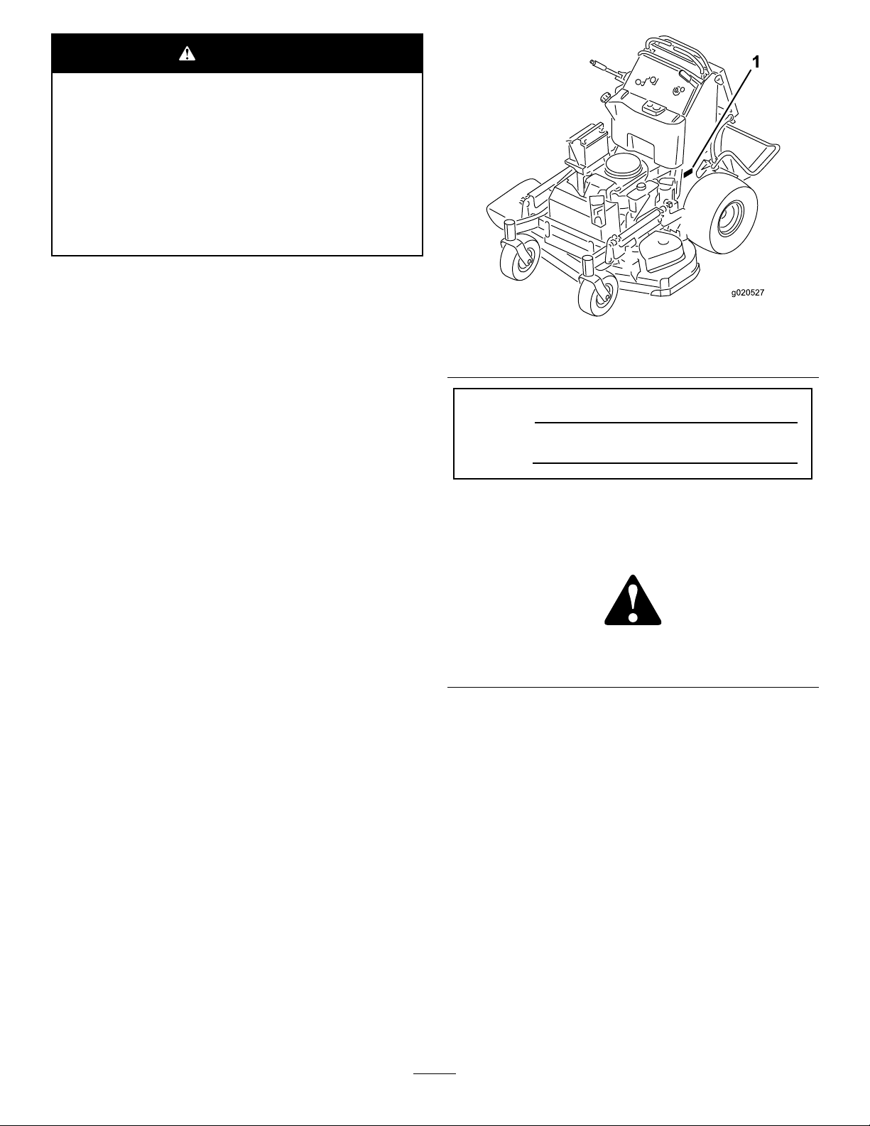
Figure1
1.Locationofthemodelandserialnumbers
ModelNo.
SerialNo.
Introduction
Thisrotary-blade,stand-onlawnmowerisintendedtobeused
byprofessional,hiredoperatorsorresidentialhomeowners.
Itisdesignedprimarilyforcuttinggrassonwell-maintained
lawnsonresidentialorcommercialproperties.Itisnot
designedforcuttingbrushorforagriculturaluses.
Readthisinformationcarefullytolearnhowtooperateand
maintainyourproductproperlyandtoavoidinjuryand
productdamage.Youareresponsibleforoperatingthe
productproperlyandsafely.
YoumaycontactT orodirectlyatwww .Toro.comforproduct
safetyandoperationtrainingmaterials,accessoryinformation,
helpndingadealer,ortoregisteryourproduct.
Wheneveryouneedservice,genuineToroparts,oradditional
information,contactanAuthorizedServiceDealerorToro
CustomerServiceandhavethemodelandserialnumbersof
yourproductready.Figure1identiesthelocationofthe
modelandserialnumbersontheproduct.Writethenumbers
inthespaceprovided.
Thismanualidentiespotentialhazardsandhassafety
messagesidentiedbythesafety-alertsymbol(Figure2),
whichsignalsahazardthatmaycauseseriousinjuryordeath
ifyoudonotfollowtherecommendedprecautions.
Figure2
1.Safety-alertsymbol
Thismanualuses2wordstohighlightinformation.
Importantcallsattentiontospecialmechanicalinformation
andNoteemphasizesgeneralinformationworthyofspecial
attention.
©2015—TheToro®Company
8111LyndaleAvenueSouth
Bloomington,MN55420
Contactusatwww.Toro.com.
2
PrintedintheUSA
AllRightsReserved

Contents
Safety...........................................................................4
SafeOperatingPractices...........................................4
ToroMowerSafety..................................................5
SoundPressure.......................................................6
SoundPower..........................................................6
VibrationLevelforModel74534TE...........................6
VibrationLevelforModel74536TE...........................6
SlopeIndicator.......................................................7
SafetyandInstructionalDecals.................................8
ProductOverview.........................................................13
Controls...............................................................13
Specications........................................................14
Operation....................................................................15
ThinkSafetyFirst...................................................15
AddingFuel...........................................................15
CheckingtheEngine-OilLevel.................................16
BreakinginaNewMachine......................................16
OperatingtheParkingBrake....................................16
OperatingtheMower-Blade-ControlSwitch
(PTO)...............................................................17
OperatingtheThrottle............................................17
OperatingtheChoke..............................................18
OperatingtheIgnitionSwitch..................................18
UsingtheFuel-ShutoffValve...................................19
StartingandStoppingtheEngine..............................19
UsingtheSafety-InterlockSystem.............................20
OperatingthePlatform...........................................21
DrivingForwardorBackward..................................22
StoppingtheMachine.............................................23
PushingtheMachinebyHand..................................23
TransportingtheMachine........................................24
LoadingtheMachine..............................................24
SideDischargingorMulchingtheGrass.....................26
AdjustingtheHeightofCut.....................................26
AdjustingtheFlowBafe........................................26
PositioningtheFlowBafe......................................27
UsingCounterweights.............................................28
Maintenance.................................................................29
RecommendedMaintenanceSchedule(s)......................29
PremaintenanceProcedures........................................30
RaisingtheMowerforAccess...................................30
ReleasingtheCushionforRearAccess.......................31
Lubrication...............................................................32
LubricatingtheMachine..........................................32
GreasingtheFrontCasterPivots..............................32
LubricatingtheCaster-WheelHubs...........................33
EngineMaintenance..................................................34
ServicingtheAirCleaner.........................................34
ServicingtheEngineOil..........................................35
ServicingtheSparkPlug..........................................37
CheckingtheSparkArrester.....................................38
FuelSystemMaintenance...........................................38
DrainingtheFuelTank...........................................38
ServicingtheFuelFilter...........................................39
ElectricalSystemMaintenance....................................39
ServicingtheBattery...............................................39
ServicingtheFuses.................................................41
DriveSystemMaintenance.........................................41
AdjustingtheTracking...........................................41
CheckingtheTirePressure......................................43
AdjustingtheCaster-PivotBearing............................43
AdjustingtheElectricClutch....................................44
CoolingSystemMaintenance......................................44
CleaningtheAir-IntakeScreen.................................44
CleaningtheCoolingSystem....................................44
BrakeMaintenance....................................................45
ServicingtheBrake.................................................45
BeltMaintenance......................................................46
CheckingtheBelts..................................................46
ReplacingtheMower-DeckBelt...............................46
ReplacingtheMower-DeckBelts..............................47
ReplacingthePump-DriveBelt................................48
ControlsSystemMaintenance.....................................49
AdjustingtheMotion-ControlHandle
Positions............................................................49
HydraulicSystemMaintenance....................................51
ServicingtheHydraulicSystem.................................51
MowerDeckMaintenance...........................................54
ServicingtheCuttingBlades.....................................54
LevelingtheMowerDeck........................................56
ReplacingtheGrassDeector..................................60
Cleaning...................................................................60
CleaningundertheMower.......................................60
DisposingofWaste.................................................60
Storage........................................................................61
CleaningandStorage..............................................61
Troubleshooting...........................................................62
Schematics...................................................................64
3

Safety
ThismachinehasbeendesignedinaccordancewithENISO
5395:2013.
Operation
•Lightningcancausesevereinjuryordeath.Iflightning
isseen,orthunderisheardinthearea,donotoperate
themachine;seekshelter.
Improperuseormaintenancebytheoperatororownercan
resultininjury.Toreducethepotentialforinjury,comply
withthesesafetyinstructionsandalwayspayattentiontothe
safetyalertsymbol,whichmeansCaution,Warning,or
Danger—personalsafetyinstruction.Failuretocomplywith
theinstructionmayresultinpersonalinjuryordeath.
SafeOperatingPractices
Training
•ReadtheOperator'sManualandothertrainingmaterial.
•Iftheoperator(s)ormechanic(s)cannotreadthemanual
language,itistheowner'sresponsibilitytoexplainthis
materialtothem.
•Becomefamiliarwiththesafeoperationoftheequipment,
operatorcontrols,andsafetysigns.
•Alloperatorsandmechanicsshouldbetrained.The
ownerisresponsiblefortrainingtheusers.
•Neverletchildrenoruntrainedpeopleoperateorservice
theequipment.Localregulationsmayrestricttheageof
theoperator.
•Theowner/usercanpreventandisresponsiblefor
accidentsorinjuriesoccurringtopeople,ordamageto
property.
Preparation
•Evaluatetheterraintodeterminewhataccessoriesand
attachmentsareneededtoproperlyandsafelyperform
thejob.Onlyuseaccessoriesandattachmentsapproved
bythemanufacturer.
•Wearappropriateclothing;includingsafetyglasses,long
pants,substantial,slip-resistantfootwear,gloves,and
hearingprotection.Tiebacklonghairanddonotwear
jewelry.
•Inspecttheareawheretheequipmentisused,andremove
allobjectsthatcanbethrownbythemachine.
•Useextracarewhenhandlingfuels.Theyareammable
andvaporsareexplosive.
–Useonlyanapprovedcontainer.
–Donotremovethefuelcaporaddfuelwiththe
enginerunning.Allowtheenginetocoolbefore
refueling.Donotsmokenearthemachinewhenthe
engineisrunning.
–Donotrefuelordrainthemachineindoors.
•Checkthattheoperator'spresencecontrols,safety
switches,andshieldsareattachedandfunctioning
properly.Donotoperatethemachineunlesstheyare
functioningproperly.
•Donotrunanengineinanenclosedarea.
•Operateonlyinwell-litareas,keepingawayfromholes
andhiddenhazards.
•Ensurethatalldrivesareinneutralandthattheparking
brakeisengagedbeforestartingengine.Starttheengine
onlyfromtheoperator’sposition.
•Makesurethatyouhavegoodfootingwhileusingthis
machine,especiallywhenbackingup.Reducedfooting
couldcauseslipping.
•Slowdownanduseextracareonhillsides.Besureto
travelsidetosideonhillsides.Turfconditionscanaffect
thestabilityofthemachine.Usecautionwhileoperating
neardrop-offs.
•Slowdownandusecautionwhenmakingturnsandwhen
changingdirectionsonslopes.
•Donotraisethemowerdeckwiththebladesrunning.
•DonotoperatethemachinewithoutthePTOshieldor
otherguardssecurelyinplace.Besurethatallinterlocks
areattached,adjustedproperly,andfunctioningproperly.
•Donotoperatewiththedischargedeectorraised,
removedoraltered,unlessyouareusingagrasscatcher.
•Donotchangetheenginegovernorsettingoroverspeed
theengine.
•Stoponlevelground,disengagedrives,engagethe
parkingbrake(ifprovided),shutofftheenginebefore
leavingtheoperator'spositionforanyreason,including
emptyingthecatchersoruncloggingthechute.
•Stopequipmentandinspectthebladesafterstriking
objectsorifanabnormalvibrationoccurs.Makethe
necessaryrepairsbeforeresumingoperations.
•Keepyourhandsandfeetawayfromthecuttingunit.
•Lookbehindanddownbeforebackinguptoensurea
clearpath.
•Keeppetsandbystandersawayfromanoperating
machine.
•Slowdownandusecautionwhenmakingturnsand
crossingroadsandsidewalks.Stopthebladesifyouare
notmowing.
•Beawareofthemower-dischargedirectionanddonot
pointitatanyone.
•Donotoperatethemowerundertheinuenceofalcohol
ordrugs.
•Usecarewhenloadingorunloadingthemachineinto
orfromatrailerortruck.
•Usecarewhenapproachingblindcorners,shrubs,trees,
orotherobjectsthatmayobscurevision.
4

SafeHandlingofFuels
•Toavoidpersonalinjuryorpropertydamage,use
extremecareinhandlinggasoline.Gasolineisextremely
ammableandthevaporsareexplosive.
•Extinguishallcigarettes,cigars,pipes,andothersources
ofignition.
•Useonlyanapprovedfuelcontainer.
•Donotremovethefuelcaporaddfuelwiththeengine
running.
•Allowtheenginetocoolbeforefueling.
•Donotfuelthemachineindoors.
•Donotstorethemachineorfuelcontainerwherethere
isanopename,spark,orpilotlight,suchasonawater
heateroronotherappliances.
•Donotllcontainersinsideavehicle,onatruck,orona
trailerbedwithaplasticliner.Alwaysplacecontainerson
thegroundawayfromyourvehiclebeforelling.
•Removeequipmentfromthetruckortrailerandfuelit
ontheground.Ifthisisnotpossible,thenaddfuelwith
suchequipmentasaportablecontainerratherthanfrom
afuel-dispensernozzle.
•Keepthenozzleincontactwiththerimofthefueltank
orcontaineropeningatalltimesuntilfuelingiscomplete.
•Donotuseanozzlelock-opendevice.
•Ifyouspillfuelonclothing,changeyourclothing
immediately.
•Donotoverllthefueltank.Replacethefuelcapand
tightensecurely.
•Keephandsandfeetawayfrommovingparts.Ifpossible,
donotmakeadjustmentswiththeenginerunning.
•Keepallpartsingoodworkingconditionandallhardware
tightened.Replaceallwornordamageddecals.
Hauling
•Usecarewhenloadingorunloadingthemachineintoa
traileroratruck.
•Usefull-widthrampsforloadingmachineintoatrailer
oratruck.
•Tiethemachinedownsecurelyusingstraps,chains,cable,
orropes.Bothfrontandrearstrapsshouldbedirected
downandoutwardfromthemachine.
ToroMowerSafety
ThefollowinglistcontainssafetyinformationspecictoToro
productsandothersafetyinformationyoumustknow .
Thisproductiscapableofamputatinghandsandfeet,and
throwingobjects.Alwaysfollowallsafetyinstructionsto
avoidseriousinjuryordeath.
Thisproductisdesignedforcuttingandrecyclinggrass,or,
whenequippedwithagrassbagger,forcatchingcutgrass.
Anyuseforpurposesotherthanthesecouldprovedangerous
totheuserandbystanders.
GeneralOperation
MaintenanceandStorage
•Disengagedrives,settheparkingbrake,stoptheengine,
andremovethekeyordisconnectspark-plugwire.Wait
forallmovementtostopbeforeadjusting,cleaning,or
repairing.
•Parkthemachineonalevelsurface.
•Cleangrassanddebrisfromthecuttingunit,drives,
mufers,andenginetohelppreventres.
•Cleanupoilorfuelspills.
•Lettheenginecoolbeforestoringthemachine.
•Donotstorefuelnearamesordrainfuelindoors.
•Donotallowuntrainedpersonneltoservicethemachine.
•Usejackstandstosupportcomponentswhenrequired.
•Carefullyreleasepressurefromcomponentswithstored
energy.
•Disconnectthebatteryorremovethespark-plugwire
beforemakinganyrepairs.Disconnectthenegative
terminalrstandthepositiveterminallast.Connectthe
positiveterminalrstandnegativelast.
•Usecarewhencheckingtheblades.Wraptheblade(s)
orwearthicklypaddedgloves,andusecautionwhen
servicingthem.Onlyreplaceblades;donotstraighten
orweldthem.
•Besurethattheareaisclearofbystandersbeforemowing.
Stopthemachineifanyoneentersthearea.
•Donottouchequipmentorattachmentpartswhichmay
behotfromoperation.Allowallofthepartstocool
beforeattemptingtomaintain,adjust,orservicethe
machine.
•UseonlyToro-approvedattachments.W arrantymaybe
voidedifusedwithanyunapprovedattachments.
•Checkcarefullyforoverheadclearances(i.e.branches,
doorways,electricalwires,etc.)beforeoperatingunder
anyobjects,anddonotcontactthem.
•Slowdownbeforemakingturnsanduseextracaution.
•Usecautionwhenridingtheplatformovercurbs,rocks,
roots,orotherobstructions.
•Lookbehindanddownbeforebackinguptoensurea
clearpath.Useextracarewhenoperatinginreverse.
•Donotjerkthecontrols;useasteadymotion.
•Whenloadingorunloadingthemachine,useone
full-widthrampthatiswideenoughtoextendbeyond
thewidthofthemachine.
•Donotcarrypassengers.
•Donotcarryequipmentonthemachine.
5

SlopeOperation
SoundPower
Allslopesandrampsrequireextracaution.Ifyoufeeluneasy
onaslope,donotmowit.
•Removeobstaclessuchasrocks,treelimbs,etc.fromthe
mowingarea.
•Watchforholes,rutsorbumps.Tallgrasscanhide
obstacles.
•Usecautionneardrop-offs,ditches,orembankments.
Themachinecouldsuddenlyturnoverifawheelgoes
overtheedgeofaclifforditch,orifanedgecavesin.
•Useextracarewithgrasscatchersorotherattachments.
Thesecanchangethestabilityofthemachine.
•Keepallmovementonslopesslowandgradual.
•Donotmakesuddenchangesinspeedordirection.
•Mowslopessidetoside.
•Donotmowslopesgreaterthan15degrees.
Service
•Donotstorethemachineorafuelcontainerinsidewhere
thereisanopename,suchasnearawaterheateror
furnace.
•Keepthenutsandboltstight,especiallythe
blade-attachmentbolts.
•Neverremoveortamperwithsafetydevices.Checktheir
properoperationregularly.Neverdoanythingtointerfere
withtheintendedfunctionofasafetydeviceortoreduce
theprotectionprovidedbyasafetydevice.
Model74534TEhasaguaranteedsoundpowerlevelof100
dBA,whichincludesanUncertaintyValue(K)of1dBA.
Model74536TEhasaguaranteedsoundpowerlevelof100
dBA,whichincludesanUncertaintyValue(K)of1dBA.
Thesoundpowerlevelwasdeterminedaccordingtothe
proceduresoutlinedinISO11094.
VibrationLevelforModel 74534TE
Hand-Arm
Measuredvibrationlevelforrighthand=0.8m/s
Measuredvibrationlevelforlefthand=0.6m/s
UncertaintyValue(K)=0.4m/s
Measuredvaluesweredeterminedaccordingtotheprocedures
outlinedinENISO5395:2013.
WholeBody
Measuredvibrationlevel=0.79m/s
UncertaintyValue(K)=0.39m/s
Measuredvaluesweredeterminedaccordingtotheprocedures
outlinedinENISO5395:2013.
2
2
2
2
2
VibrationLevelforModel
•Tobestprotectyourinvestmentandmaintainoptimal
performanceofyourToroequipment,countonToro
genuineparts.Whenitcomestoreliability,Torodelivers
replacementpartsdesignedtotheexactengineering
specicationsofourequipment.Forpeaceofmind,insist
onTorogenuineparts.
•Checkbrakeoperationfrequently.Adjustandserviceas
required.
SoundPressure
Model74534TEhasasoundpressurelevelattheoperator’s
earof88dBA,whichincludesanUncertaintyValue(K)of
1dBA.
Model74536TEhasasoundpressurelevelattheoperator’s
earof86dBA,whichincludesanUncertaintyValue(K)of
1dBA.
Thesoundpressurelevelwasdeterminedaccordingtothe
proceduresoutlinedinENISO5395:2013.
74536TE
Hand-Arm
Measuredvibrationlevelforrighthand=1.1m/s
Measuredvibrationlevelforlefthand=1.1m/s
UncertaintyValue(K)=0.6m/s
Measuredvaluesweredeterminedaccordingtotheprocedures
outlinedinENISO5395:2013.
WholeBody
Measuredvibrationlevel=0.79m/s
UncertaintyValue(K)=0.39m/s
Measuredvaluesweredeterminedaccordingtotheprocedures
outlinedinENISO5395:2013.
2
2
2
2
2
6
SlopeIndicator
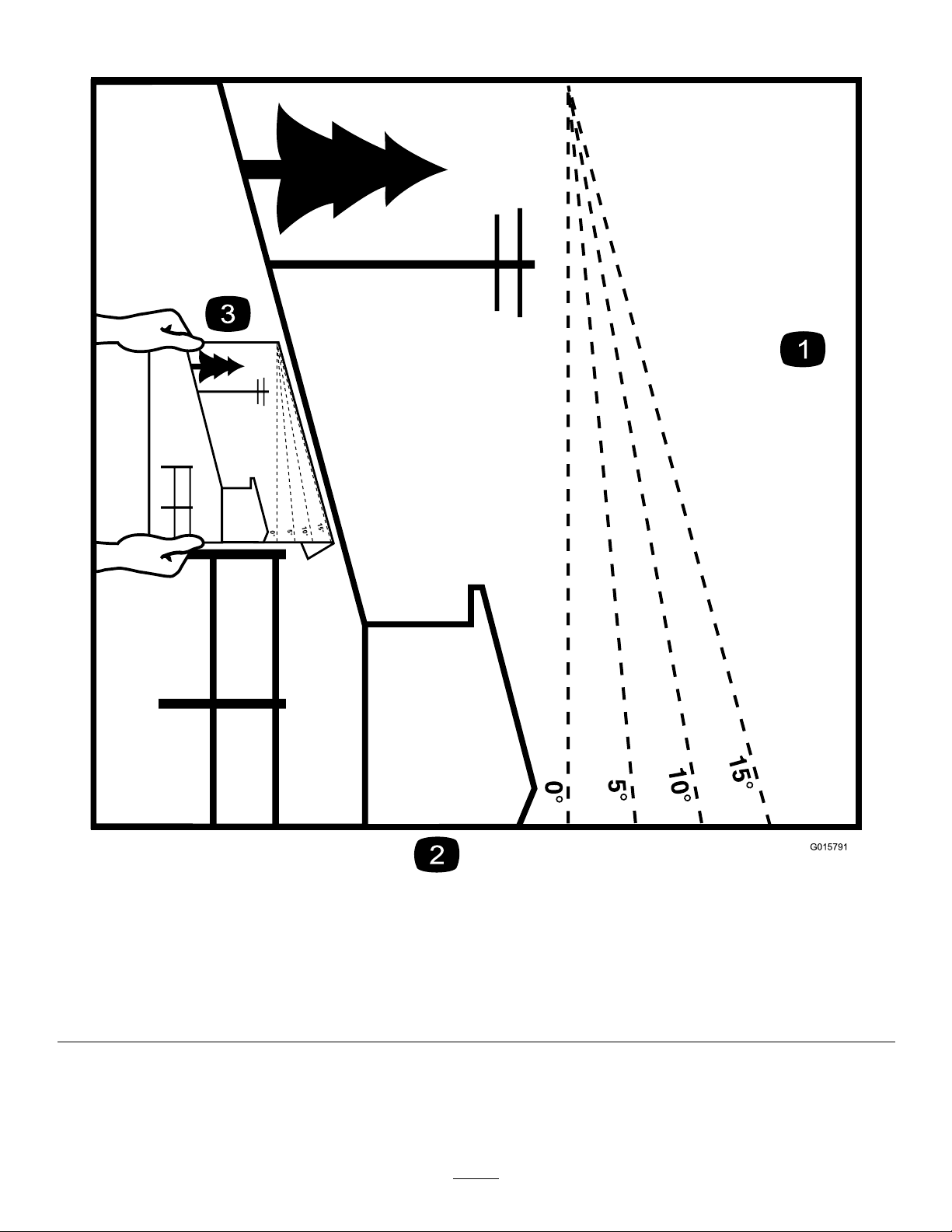
G015791
Figure3
Thispagemaybecopiedforpersonaluse.
1.Themaximumslopeyoucansafelyoperatethemachineonis15degrees.Usetheslopecharttodeterminethedegreeofslope
ofhillsbeforeoperating.Donotoperatethismachineonaslopegreaterthan15degrees.Foldalongtheappropriateline
tomatchtherecommendedslope.
2.Alignthisedgewithaverticalsurface,atree,building,fencepole,etc.
3.Exampleofhowtocompareslopewithfoldededge.
7
SafetyandInstructionalDecals
Safetydecalsandinstructionsareeasilyvisibletotheoperatorandarelocatednearanyareaofpotential
danger.Replaceanydecalthatisdamagedorlost.
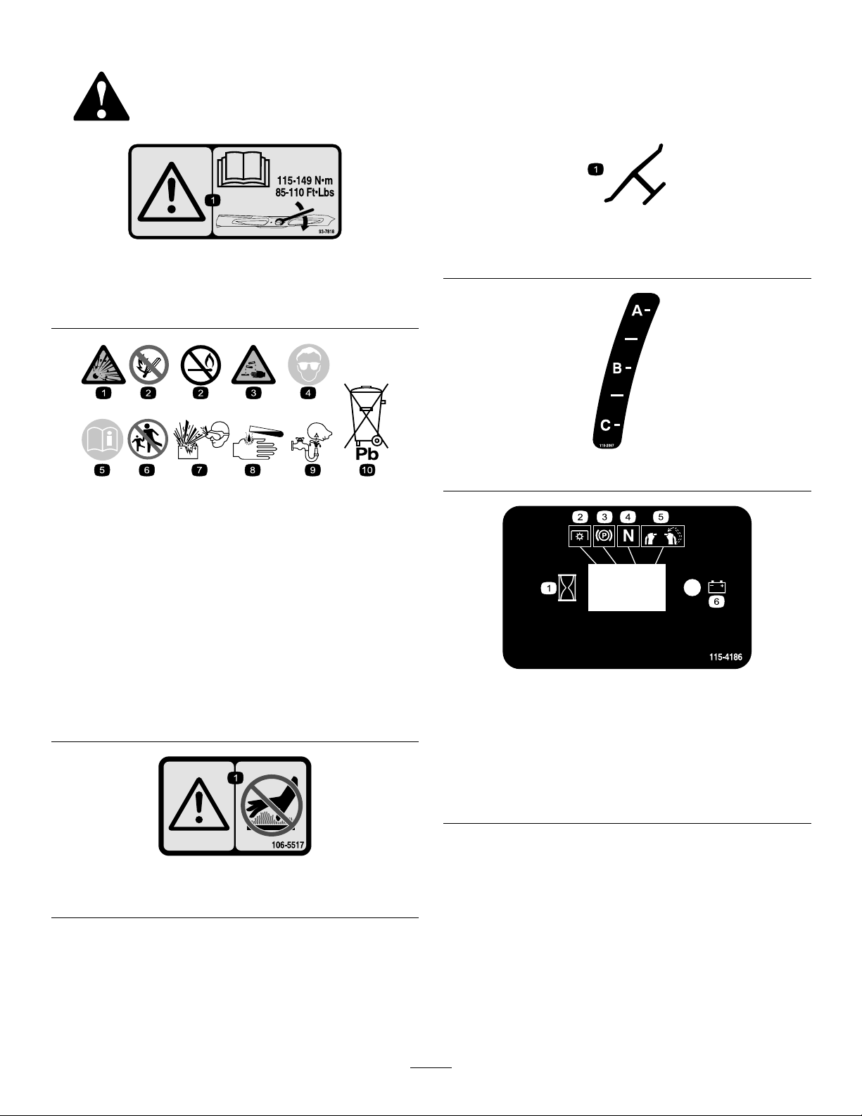
Manufacturer'sMark
93-7818
1.Warning—readtheOperator'sManualforinstructionson
torquingthebladebolt/nutto1 15to149N∙m(85to110
ft-lb).
BatterySymbols
Someorallofthesesymbolsareonyourbattery
1.Explosionhazard
2.Nore,opename,or
smoking.
3.Causticliquid/chemical
burnhazard
4.Weareyeprotection.9.Flusheyesimmediately
5.ReadtheOperator's
Manual.
6.Keepbystandersasafe
distancefromthebattery.
7.Weareyeprotection;
explosivegasescan
causeblindnessandother
injuries.
8.Batteryacidcancause
blindnessorsevereburns.
withwaterandgetmedical
helpfast.
10.Containslead;donot
discard.
1.Indicatesthebladeisidentiedasapartfromtheoriginal
machinemanufacturer.
110-2067
115-4186
1.Interval
2.Powertakeoff(PTO)
3.Parkingbrake
4.Neutral
5.Operator-presenceswitch
6.Battery
1.Warning—donottouchthehotsurface.
106-5517
8
115-4212
1.Hydraulicoillevel3.Warning—donottouchthe
hotsurface.
2.ReadtheOperator's
Manual.
116-3290
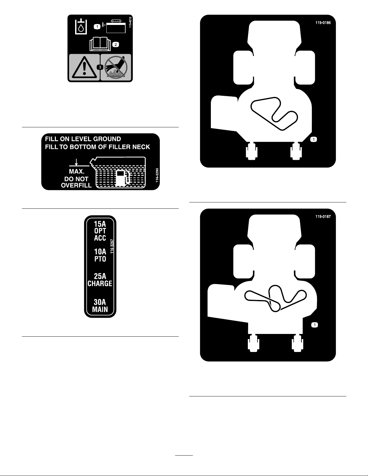
119-0186
Modelswith91cmDecksOnly
1.Beltrouting
116-3267
119-0187
Modelswith102cmDecksOnly
1.Beltrouting
9
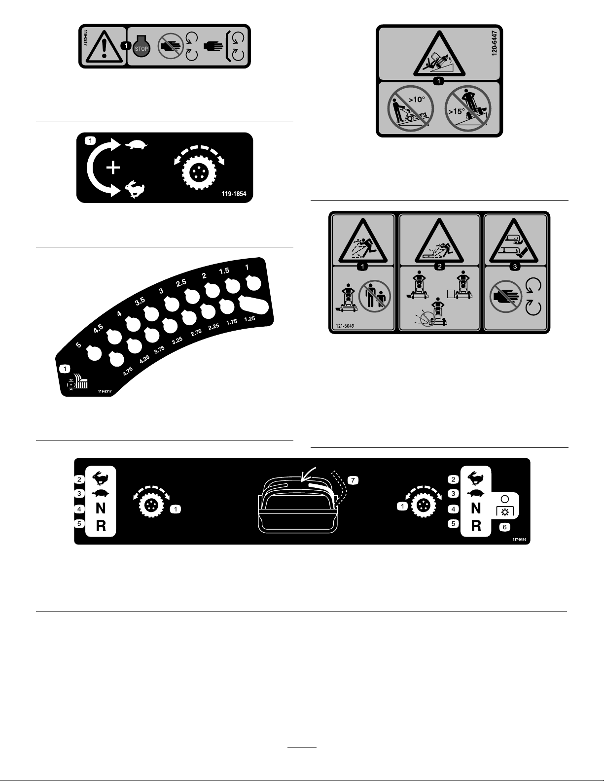
119-0217
1.Warning—stoptheengine;stayawayfrommovingparts;
keepallguardsandshieldsinplace.
119-1854
1.Adjustmentknobfortractiondrivespeed
120-6447
1.Tippinghazard—donotmowupanddownslopesgreater
than10degrees;donotmowacrossslopesgreaterthan
15degrees.
121-6049
119-2317
1.Heightofcut(inches)
1.Tractioncontrol
2.Fast4.Neutral
1.Thrownobject
hazard—keepbystanders
awayfromthemachine.
2.Thrownobjecthazard,
mower—donotoperate
themowerwithguardsor
shieldsremoved.
3.Cutting/dismemberment
hazardofhandorfoot,
mowerblade—keephands
awayfrommovingparts.
117-0454
3.Slow
5.Reverse
6.Powertakeoff
(PTO)—disengage
7.Operator-presenceswitch
10
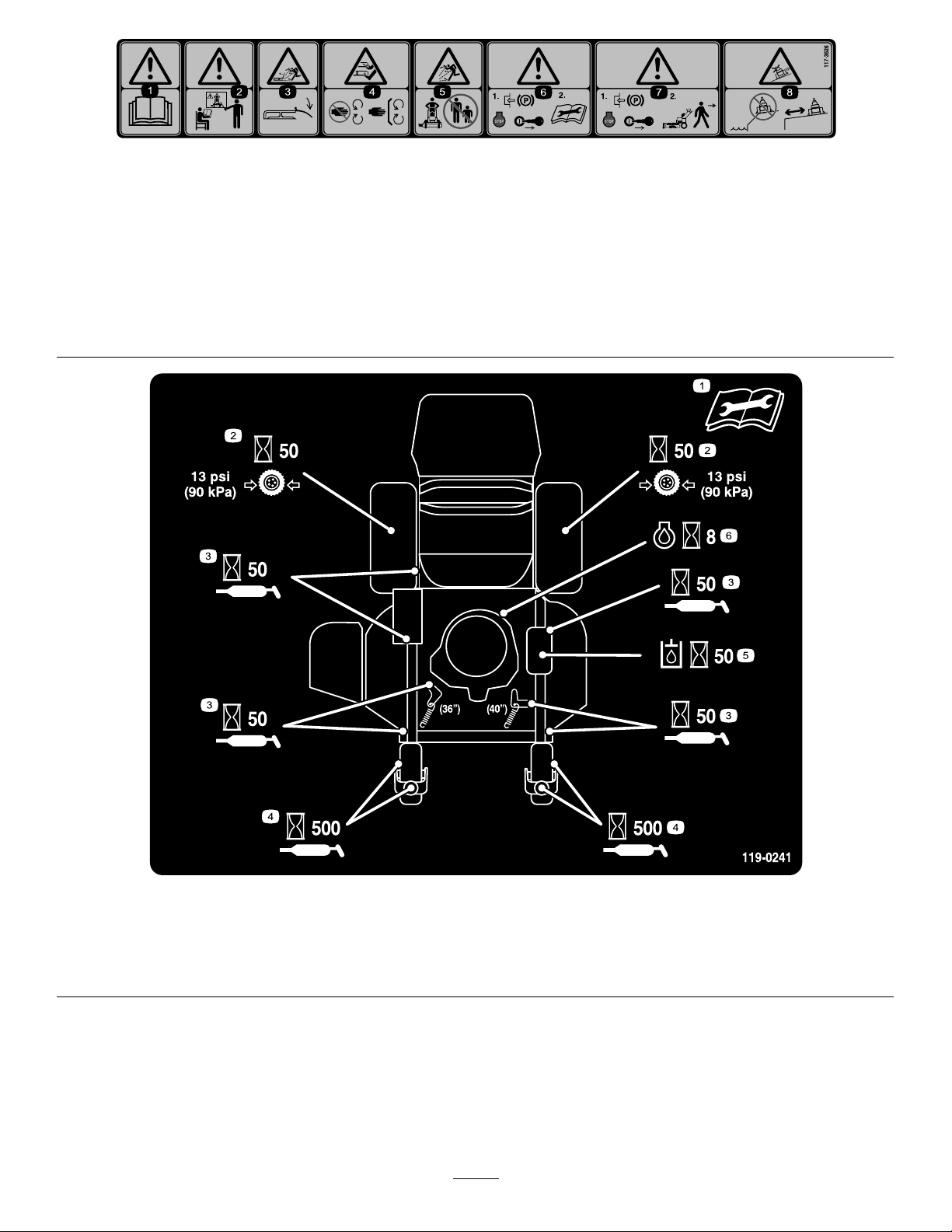
117-3626
1.Warning—readtheOperator'sManual.5.Thrownobjecthazard—keepbystandersasafedistancefrom
2.Warning—donotoperatethismachineunlessyouaretrained.6.Warning—engagetheparkingbrake,stoptheengine
3.Thrownobjecthazard—keepdeectorinplace.
4.Cutting,dismembermenthazardofhandorfoot—stayaway
frommovingpartsandkeepallguardsandshieldsinplace.
themachine.
andremovethesparkplugwirebeforeperformingany
maintenanceonthemachine.
7.Warning—engagetheparkingbrakeandstoptheengine
beforeleavingthemachine.
8.Slidingandlossofcontrolhazard—donotoperatethe
machineneardrop-offsorwater;keepasafedistancefrom
drop-offs.
1.ReadtheOperator'sManualbefore
performinganymaintenance.
2.Checkthedrivewheeltirepressure
every50hours.
119-0241
3.Lubricateevery50hours.
4.Lubricatethecasterwheelevery500
hours.
11
5.Checkthehydraulicoilevery50hours.
6.Checktheengineoilevery8hours.

0
00
00
125-4679
1.Parkingbrake—disengaged5.Enginespeed
2.Parkingbrake—engaged
3.PTO—engaged7.Continuous-variablesetting
4.PTO—disengaged
6.Slow
8.Fast
12
ProductOverview
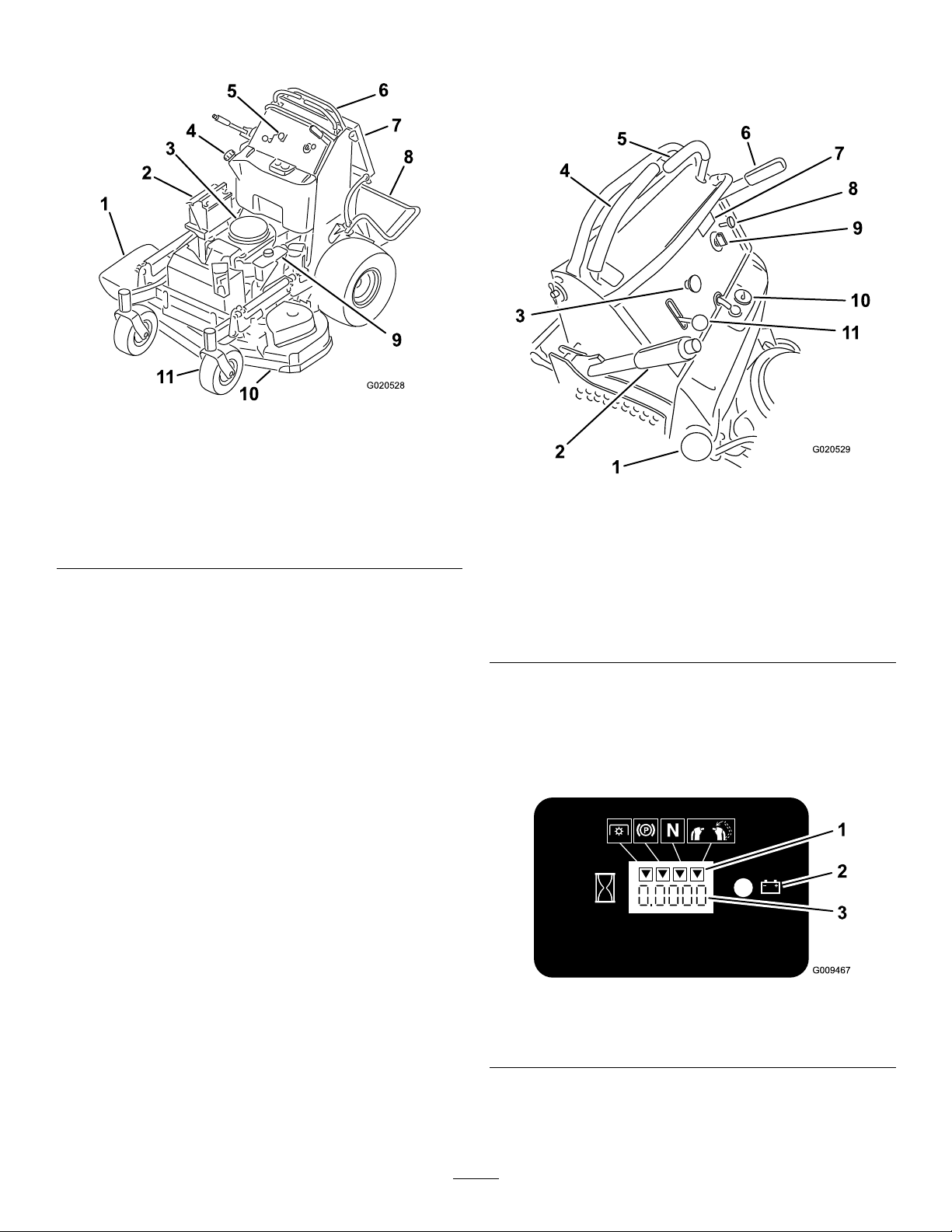
G020528
7
8
9
10
11
1
7
2
8
3
9
4
10
5
11
6
G020529
Figure4
1.Side-dischargechute7.Operatorcushion
2.Battery
3.Engine9.Hydraulictank
4.Fueltank10.Mowerdeck
5.Controls
6.Motion-controllevers
8.Platform(downposition)
11.Frontcasterwheel
Controls
Becomefamiliarwithallthecontrols(Figure5)beforeyou
starttheengineandoperatethemachine.
Figure5
1.Fuelcap7.Hourmeter
2.Height-of-cutlever8.Choke
3.Blade-controlswitch
(PTO)
4.Rightmotion-controllever10.Fuelgauge
5.Leftmotion-controllever
6.Parking-brakelever
9.Ignitionswitch
11.Throttlecontrol
HourMeter
Thehourmeterrecordsthenumberofhourstheenginehas
operated.Itoperateswhentheengineisrunning.Usethese
timesforschedulingregularmaintenance(Figure6).
1.Safety-interlocksymbols
2.Batterylight
Figure6
3.Hourmeter
13

FuelGauge
Attachments/Accessories
Thefuelgaugeislocatedonthetop,middleofthetank
(Figure5).
Safety-interlockIndicators
Therearesymbolsonthehourmeterandindicatewitha
blacktrianglethattheinterlockcomponentisinthecorrect
position(Figure6).
Battery-indicatorLight
IftheignitionkeyisturnedtotheONpositionforafew
seconds,thebatteryvoltagebedisplaysintheareawherethe
hoursarenormallydisplayed.
Thebatterylightturnsonwhentheignitionisturnedonand
whenthechargeisbelowthecorrectoperatinglevel(Figure
6).
ThrottleControl
ThethrottlecontrolisvariablebetweentheFASTandSLOW
positions.
AselectionofToroapprovedattachmentsandaccessoriesis
availableforusewiththemachinetoenhanceandexpand
itscapabilities.ContactyourAuthorizedServiceDealeror
Distributororgotowww .Toro.comforalistofallapproved
attachmentsandaccessories.
Specications
Note:Specicationsanddesignaresubjecttochange
withoutnotice.
Model74534TE
Cuttingwidth91cm(36inches)
Widthwithdeectordown131cm(52inches)
Lengthwithplatformdown188cm(74inches)
Lengthwithplatformup155cm(61inches)
Height
Weight
Model74536TE
122cm(48inches)
343kg(756lb)
Choke
Usethechoketostartacoldengine.
Blade-ControlSwitch(PTO)
Usetheblade-controlswitch(PTO)toengagetheelectric
clutchtodrivethemowerbladeswitheithermotion-control
leverinthecenter,unlockedposition(Figure5).Pullthe
switchuptoengagethebladesandrelease.Todisengagethe
blades,pushtheblade-controlswitch(PTO)down,ormove
orreleasethemotion-controlleversintotheNEUTRAL-LOCK
position.
IgnitionSwitch
Usetheignitionswitchtostartthemowerengine(Figure5).
Theswitchhas3positions:OFF,RUN,andSTART.
Motion-controlLevers
Themotion-controlleversareusedtodrivethemachine
forward,reverse,andturneitherdirection.
Cuttingwidth102cm(40inches)
Widthwithdeectordown142cm(56inches)
Lengthwithplatformdown178cm(70inches)
Lengthwithplatformup145cm(57inches)
Height
Weight
122cm(48inches)
351kg(773lb)
Fuel-ShutoffValve
Closethefuel-shutoffvalve(locatedbehindtheoperator
cushionontherighthandsideoffueltank)whentransporting
orstoringthemower.
14
Operation
G009027
1
2
ThinkSafetyFirst
Carefullyreadallthesafetyinstructionsanddecalsinthe
safetysection.Knowingthisinformationcouldhelpyouor
bystandersavoidinjury.
CAUTION
Thismachineproducessoundlevelsinexcessof
85dBAattheoperator'searandcancausehearing
lossfromextendedperiodsofexposure.
Wearhearingprotectionwhenoperatingthis
machine.
DANGER
Incertainconditions,gasolineisextremely
ammableandhighlyexplosive.Areorexplosion
fromgasolinecanburnyouandothersandcan
damageproperty.
•Fillthefueltankoutdoors,inanopenarea,
whentheengineiscold.Wipeupanygasoline
thatspills.
•Neverllthefueltankinsideanenclosedtrailer.
•Donotllthefueltankcompletelyfull.Add
gasolinetothefueltankuntilthelevelis6to13
mm(1/4to1/2inch)belowthebottomofthe
llerneck.Thisemptyspaceinthetankallows
gasolinetoexpand.
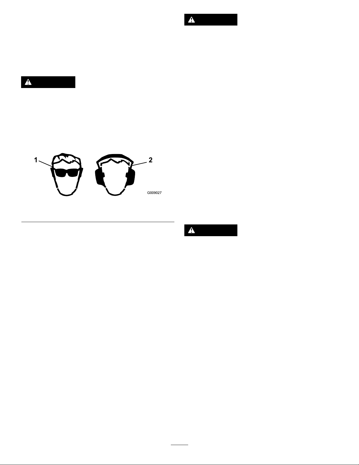
Useprotectiveequipmentforyoureyes,ears,andfeet.
Figure7
1.Wearsafetyglasses.
2.Wearhearingprotection.
AddingFuel
•Forbestresults,useonlyclean,fresh(lessthan30days
old),unleadedgasolinewithanoctaneratingof87or
higher((R+M)/2ratingmethod).
•Ethanol:Gasolinewithupto10%ethanol(gasohol)
or15%MTBE(methyltertiarybutylether)byvolume
isacceptable.EthanolandMTBEarenotthesame.
Gasolinewith15%ethanol(E15)byvolumeisnot
approvedforuse.Neverusegasolinethatcontains
morethan10%ethanolbyvolume,suchasE15
(contains15%ethanol),E20(contains20%ethanol),or
E85(containsupto85%ethanol).Usingunapproved
gasolinemaycauseperformanceproblemsand/orengine
damagewhichmaynotbecoveredunderwarranty.
•Donotusegasolinecontainingmethanol.
•Donotstorefueleitherinthefueltankorfuelcontainers
overthewinterunlessyouuseafuelstabilizer.
•Donotaddoiltogasoline.
•Neversmokewhenhandlinggasoline,andstay
awayfromanopenameorwheregasoline
fumesmaybeignitedbyaspark.
•Storegasolineinanapprovedcontainerand
keepitoutofthereachofchildren.Neverbuy
morethana30-daysupplyofgasoline.
•Donotoperatewithoutentireexhaustsystemin
placeandinproperworkingcondition.
DANGER
Incertainconditionsduringfueling,static
electricitycanbereleasedcausingaspark,which
canignitethegasolinevapors.Areorexplosion
fromgasolinecanburnyouandothersandcan
damageproperty.
•Alwaysplacegasolinecontainersontheground
awayfromyourvehiclebeforelling.
•Donotllgasolinecontainersinsideavehicleor
onatruckortrailerbedbecauseinteriorcarpets
orplastictruckbedlinersmayinsulatethe
containerandslowthelossofanystaticcharge.
•Whenpractical,removegas-poweredequipment
fromthetruckortrailerandrefueltheequipment
withitswheelsontheground.
•Ifthisisnotpossible,thenrefuelsuch
equipmentonatruckortrailerfromaportable
containerratherthanfromagasoline-dispenser
nozzle.
•Ifyoumustuseagasoline-dispensernozzle
mustbeused,keepthenozzleincontactwith
therimofthefueltankorcontaineropeningat
alltimesuntilfuelingiscomplete.
15

WARNING
BreakinginaNewMachine
Gasolineisharmfulorfatalifswallowed.Long-term
exposuretovaporscancauseseriousinjuryand
illness.
•Avoidprolongedbreathingofvapors.
•Keepfaceawayfromnozzleandgastankor
conditionerbottleopening.
•Avoidcontactwithskin;washoffspillswith
soapandwater.
UsingStabilizer/Conditioner
Useafuelstabilizer/conditionerinthemachinetoprovide
thefollowingbenets:
•Keepsgasolinefreshduringstorageof90daysorless.
Forlongerstorage,drainthefueltank.
•Cleanstheenginewhileitruns
•Eliminatesgum-likevarnishbuildupinthefuelsystem,
whichcauseshardstarting
Important:Donotusefueladditivescontaining
methanolorethanol.
Addthecorrectamountofgasstabilizer/conditionerto
thegas.
Note:Afuelstabilizer/conditionerismosteffective
whenmixedwithfreshgasoline.Tominimizethechance
ofvarnishdepositsinthefuelsystem,usefuelstabilizer
atalltimes.
Newenginestaketimetodevelopfullpower.Mowerdecks
anddrivesystemshavehigherfrictionwhennew,placing
additionalloadontheengine.Allow40to50hoursof
break-intimefornewmachinestodevelopfullpowerand
bestperformance.
OperatingtheParkingBrake
Alwayssettheparkingbrakewhenyoustopthemachineor
leaveitunattended.Beforeeachuse,checktheparkingbrake
forproperoperation.
Iftheparkingbrakedoesnotholdsecurely,adjustit;referto
AdjustingtheBrakes(page46).
CAUTION
Childrenorbystandersmaybeinjuredifthey
moveorattempttooperatethemachinewhileitis
unattended.
Alwaysremovetheignitionkeyandsettheparking
brakewhenleavingthemachineunattended.
SettingtheParkingBrake
Pulltheparking-brakeleverrearwardintotheENGAGED
position(Figure8).
FillingtheFuelT ank
1.Parkthemachineonlevelground.
2.Shuttheengineoffandsettheparkingbrake.
3.Cleanaroundthefuel-tankcapandremovethecap.
4.Fillthefueltanktothebottomofthellerneck.
Note:Donotllthefueltankcompletelyfull.The
emptyspaceinthetankallowsthegasolinetoexpand.
5.Installthefuel-tankcapsecurely.Wipeupanygasoline
thatmayhavespilled.
CheckingtheEngine-OilLevel
Beforeyoustarttheengineandusethemachine,check
theoillevelintheenginecrankcase;refertoCheckingthe
Engine-OilLevel(page35).
Figure8
1.Parkingbrakeengaged2.Parkingbrakereleased
ReleasingtheParkingBrake
Pushtheparking-brakeleverforward(Figure8).
16
Operatingthe
g012781
g012782
g012895
G008946
Mower-Blade-ControlSwitch
(PTO)
Theblade-controlswitch(PTO)isusedinconjunctionwith
therightmotion-controllevertoengageanddisengagethe
mowerblades.
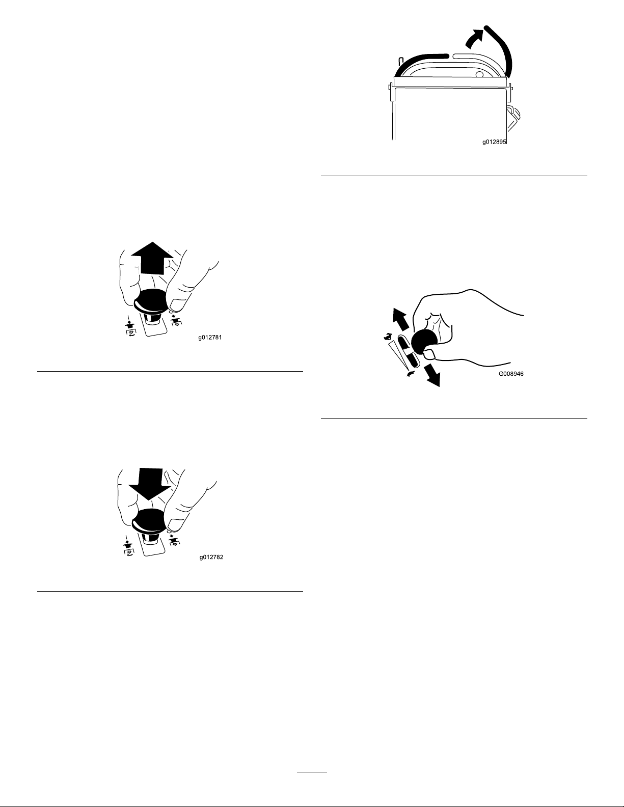
EngagingtheMowerBlades(PTO)
1.Toengagethemowerblades,movetheright
motion-controllevertothecenter,unlockedposition.
2.Pulltheblade-controlswitch(PTO)upandreleaseit
whileholdingdowntherightmotion-controlleverin
thecenter,unlockedposition.
Figure9
DisengagingtheMowerBlades(PTO)
Thefollowingare2optionsfordisengagingthemowerblades:
•Pushtheblade-controlswitch(PTO)downtotheOFF
position(Figure10).
Figure11
OperatingtheThrottle
ThethrottlecontrolmovesbetweenFASTandSLOWpositions
(Figure12).
AlwaysusetheFASTpositionwhenengagingthemower
bladeswiththeblade-controlswitch(PTO).
Figure12
Figure10
•Movethemotion-controlleverstoNEUTRALandmove
therightmotion-controlleverintotheNEUTRAL-LOCK
position(Figure11).
17
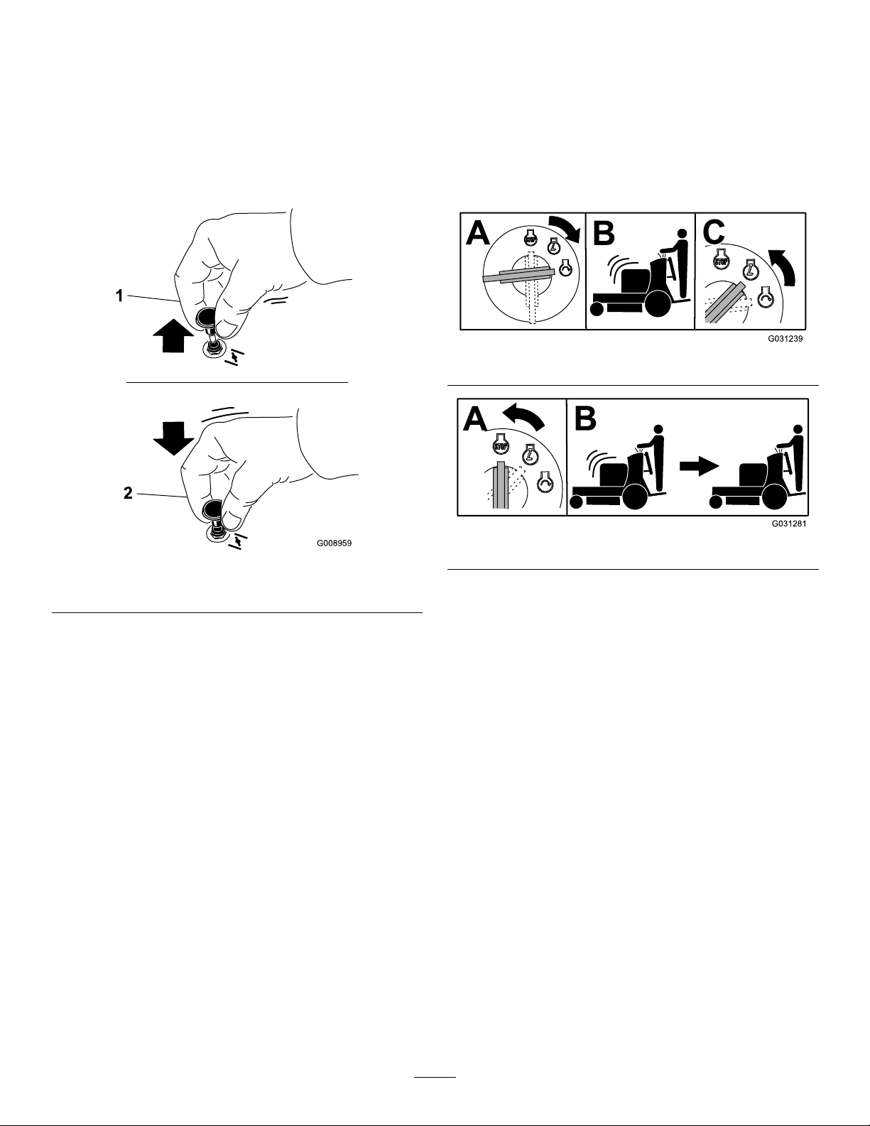
OperatingtheChoke
G008959
1
2
OperatingtheIgnitionSwitch
Usethechoketostartacoldengine.
1.Iftheengineiscold,usethechoketostarttheengine.
2.Pulluponthechokeknobtoengagethechokebefore
usingtheignitionswitch(Figure13).
3.Pushdownonthechokeknobtodisengagethechoke
aftertheenginehasstarted(Figure13).
Important:Donotengagethestarterformorethan
5secondsatatime.Iftheenginefailstostart,wait
15secondsbetweenattempts.Failuretofollowthese
instructionscanburnoutthestartermotor.
Note:Youmayneedtorepeatthecycleforstartingthe
enginewhenyoustartitforthersttimeafteryouhavelled
acompletelyemptyfuelsystemwithfuel.
Figure14
Figure15
Figure13
1.Onposition2.Offposition
18
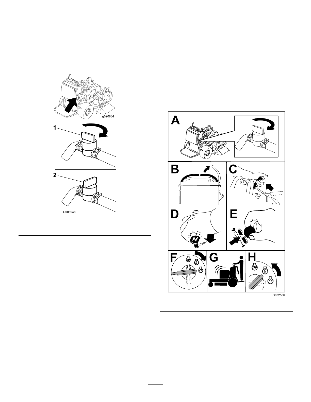
UsingtheFuel-ShutoffValve
g020864
G008948
1
2
StartingandStoppingthe
Thefuel-shutoffvalveislocatedbehindtherightsideofthe
operatorcushion.
Closethefuel-shutoffvalvefortransport,maintenance,and
storage(Figure16).
Ensurethatthefuel-shutoffvalveisopenwhenstartingthe
engine.
Engine
StartingtheEngine
Important:Donotengagethestarterformorethan
5secondsatatime.Iftheenginefailstostart,wait
15secondsbetweenattempts.Failuretofollowthese
instructionscanburnoutthestartermotor.
Note:Awarmorhotenginemaynotrequirechoking.
Note:Youmayneedtorepeatthecycleforstartingthe
enginewhenyoustartitforthersttimeafteryouhavelled
acompletelyemptyfuelsystemwithfuel.
Figure16
1.Onposition2.Offpositon
Figure17
19
StoppingtheEngine
UsingtheSafety-Interlock
CAUTION
Childrenorbystandersmaybeinjuredifthey
moveorattempttooperatethetractorwhileitis
unattended.
Alwaysremovetheignitionkeyandsettheparking
brakewhenleavingthemachineunattended,even
ifjustforafewminutes.
System
CAUTION
Ifthesafety-interlockswitchesaredisconnectedor
damaged,themachinecouldoperateunexpectedly,
causingpersonalinjury.
•Donottamperwiththeinterlockswitches.
•Checktheoperationoftheinterlockswitches
dailyandreplaceanydamagedswitchesbefore
operatingthemachine.
UnderstandingtheSafety-Interlock
System
Thesafety-interlocksystemisdesignedtopreventthemower
bladesfromrotatingunless1ofthefollowingoccur:
•Youmovetherightmotion-controllevertothecenter,
unlockedposition.
•Theblade-controlswitch(PTO)isengaged.
Thesafety-interlocksystemisdesignedtostopthemower
bladesifyoumoveorreleasetherightmotion-control
leverintotheNEUTRAL-LOCKposition.
Figure18
Important:Makesurethatthefuel-shutoffvalveis
closedbeforetransportingorstoringthemachine,as
fuelleakagemayoccur.Beforestoringthemachine,pull
wireoffsparkplug(s)topreventpossibilityofaccidental
starting.
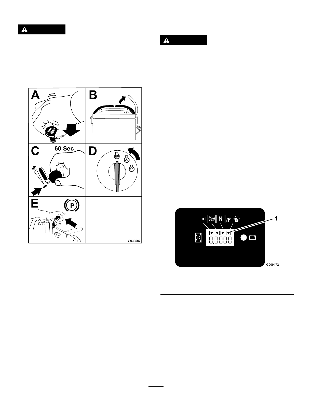
Thehourmeterhassymbolstonotifyyouwhenthe
interlockcomponentisinthecorrectposition.Whenthe
componentisinthecorrectposition,atrianglelightsup
inthecorrespondingsquare.
Figure19
1.Triangleslightupwhentheinterlockcomponentsareinthe
correctposition.
TestingtheSafety-InterlockSystem
ServiceInterval:Beforeeachuseordaily
Testthesafety-interlocksystembeforeyouusethemachine
eachtime.
Note:Ifthesafetysystemdoesnotoperateasdescribed
below,haveanAuthorizedServiceDealerrepairthesafety
systemimmediately.
1.Starttheengine;refertoStartingtheEngine(page19).
2.Settheparkingbrake.
20

3.Movetherightmotion-controllevertothecenter,
unlockedposition.
Note:Thebladesshouldnotrotate.
4.Movethemotion-controlleversforward.
OperatingthePlatform
Youcanusethemachinewiththeplatformintheupordown
position.Itisyourpreferenceonwhichpositiontouse.
Note:Theengineshouldstoprunning.
5.Starttheengineandreleasetheparkingbrake.
6.Movetherightmotion-controllevertothecenter,
unlockedposition.
7.Continueholdingtherightmotion-controlleverinthe
center,unlockedposition,pulluptheblade-control
switch(PTO),andrelease.
Note:Theclutchshouldengageandthemower
bladesshouldrotate.
8.Moveorreleasetherightmotion-controlleverintothe
neutral-lockposition.
Note:Thebladesshouldstoprotatingandtheengine
shouldcontinuetorun.
9.Pushtheblade-controlswitchdownandmovetheright
motion-controllevertothecenter,unlockedposition.
10.Continueholdingtherightmotion-controlleverinthe
center,unlockedposition,pullupontheblade-control
switch(PTO),andrelease.
Note:Theclutchshouldengageandthemower
bladesshouldrotate.
11.Pushtheblade-controlswitch(PTO)downtotheOFF
position.
OperatingtheMachinewiththe
PlatformUp
Operatethemachinewiththeplatformupforthefollowing
conditions:
•Mowingneardrop-offs
•Mowingsmallareaswherethemachineistoolarge
•Areaswithlow ,over-hangingbranchesorobstacles
•Loadingthemachinefortransport
•Drivingupslopes
Toraisetheplatform,pullthebackoftheplatformupsothat
thelatchpinandknoblockitintoplace.Pushittightagainst
thecushionforthelatchpintolockitintoplace.
OperatingtheMachinewiththe
PlatformDown
Operatethemachinewiththeplatformdownforthe
followingconditions:
•Mowingmostareas
•Drivingacrossslopes
•Drivingdownslopes
Note:Thebladesshouldstoprotating.
12.Withtheenginerunning,pulluptheblade-control
switch(PTO)andreleaseitwithoutholdingright
motion-controllevertothecenter,unlockedposition.
Note:Thebladesshouldnotrotate.
WARNING
Theoperatorplatformisheavyandmaycause
injurywhenloweringandraisingtheoperator
platform.Carefullylowerorraisetheoperator
platform,assuddenlydroppingitcouldinjureyou.
•Donotputyourhandsorngersinthe
platform-pivotareawhenloweringorraisingthe
operatorplatform.
•Makesurethattheplatformissupportedwhen
youpullthelatchpinout.
•Makesurethatthelatchsecurestheplatform
whenfoldingitup.Pushittightagainstthe
cushionforthelatchpintolockintoplace.
•Keepbystandersawaywhenraisingorlowering
theplatform.
Tolowertheplatform,pushtheplatformforwardagainstthe
cushiontoreleasepressureonthelatchpin,pulltheknob
out,andlowertheplatform(Figure20).
21

g020804
1.Platformup
G020531
4
5
1
2
3
2 4
2.Platformdown
Figure20
3.Pulltheknobouttorelease
theplatform.
1.Frontreferencebar
2.Leftcontrollever
3.Rearreferencebar
Figure21
4.Rightcontrollever
5.Rightcontrolleverinthe
NEUTRAL-LOCKposition
DrivingForwardorBackward
Thethrottlecontrolregulatestheenginespeedasmeasured
inrpm(revolutionsperminute).Placethethrottlecontrolin
theFASTpositionforbestperformance.Alwaysoperatein
thefull-throttlepositionwhenmowing.
CAUTION
Themachinecanspinveryrapidly,andyoumay
losecontrolofmachine,causingpersonalinjuryto
youanddamagetomachine.
Slowthemachinedownbeforemakingsharpturns.
DrivingForward
1.Releasetheparkingbrake;refertoReleasingthe
ParkingBrake(page16).
2.Movetherightmotion-controllevertothecenter,
unlockedposition.
3.Togoforward,movethespeed-controllevertothe
desiredspeed.
4.Slowlypushthemotion-controlleversforward(Figure
22).
Note:Theenginestopsifyoumoveamotion-control
leverwiththeparkingbrakeengaged.
Note:Thefartheryoumovethemotion-controllevers
ineitherdirection,thefasterthemachinemovesinthat
direction.
Note:Tostop,pullthemotion-controlleversback
totheNEUTRALposition.
22

StoppingtheMachine
Tostopthemachine,movethemotion-controlleversto
NEUTRAL,movetherightmotion-controlleverintothe
NEUTRAL-LOCKposition,disengagethepowertakeoff
(PTO),andturntheignitionkeytotheOFFposition.
Settheparkingbrakewhenyouleavethemachine;referto
SettingtheParkingBrake(page16).Removethekeyfrom
theignitionswitch.
CAUTION
Childrenorbystandersmaybeinjurediftheymove
orattempttooperatethemachine.
Alwaysremovetheignitionkeyandsettheparking
brakewhenleavingthemachineunattended.
PushingtheMachinebyHand
Figure22
DrivingBackward
1.Movetherightmotion-controllevertothecenter,
unlockedposition.
2.Slowlypullthemotion-controlleversrearward(Figure
23).
Thebypassvalvesallowthemachinetobepushedbyhand
withouttheenginerunning.
Important:Alwayspushthemachinebyhand.Never
towthemachine,becausehydraulicdamagemayoccur.
1.DisengagethePTO,movethemotion-controllevers
totheNEUTRAL-LOCKEDposition,andsettheparking
brake.
2.Lowerthemowerdecktothelowestheightofcut
(HOC).
Note:Thisallowsaccesstothebypassvalves.
3.Openthebypassvalveonbothpumpsbyturningthem
counterclockwise1to2turns(Figure24).
Note:Thisallowshydraulicuidtobypassthepumps
andthewheelstoturn.
Note:Rotatethebypassvalvesamaximumof2
turnssothatthevalvedoesnotcomeoutofthebody,
causinguidtorunout.
Figure23
23

g020805
1.Tractionunittie-downloop
Figure25
Figure24
1.Pump-bypassvalve
4.Releasetheparkingbrake.
5.Pushthemachinetothedesiredlocation.
6.Settheparkingbrake.
7.Closethebypassvalvesbutdonotovertightenthem.
8.Torquethevalvesto12to15N∙m(110to130in-lb).
Important:Donotstartoroperatethemachine
withthebypassvalvesopen.Damagetosystem
mayoccur.
TransportingtheMachine
Useaheavy-dutytrailerortrucktotransportthemachine.
Ensurethatthetrailerortruckhasallnecessarybrakes,
lighting,andmarkingasrequiredbylaw .Pleasecarefullyread
allthesafetyinstructions.
1.Raisetheplatformofthemachinebeforedrivingup
ontothetrailerortruck.
2.Ifusingatrailer,connectittothetowingvehicleand
connectthesafetychains.
3.Ifapplicable,connectthetrailerbrakes.
4.Loadthemachineontothetrailerortruck.
5.Shutofftheengine,removethekey,setthebrake,and
closethefuelvalve.
LoadingtheMachine
Useextremecautionwhenloadingorunloadingmachines
ontoatraileroratruck.Useafull-widthrampthatiswider
thanthemachineforthisprocedure.Backthemachineupthe
rampandwalkitforwarddowntheramp(Figure26).
Figure26
1.Backthemachineupthe
ramp.
Important:Donotusenarrowindividualrampsfor
eachsideofthemachine.
Ensurethattherampislongenoughsothattheanglewith
thegrounddoesnotexceed15degrees(Figure27).Onat
ground,thisrequiresaramptobeatleast4timesaslongas
theheightofthetrailerortruckbedtotheground.Asteeper
anglemaycausemowercomponentstogetcaughtasthe
machinemovesfromtheramptothetrailerortruck.Steeper
anglesmayalsocausethemachinetotiporlosecontrol.If
youareloadingthemachineonornearaslope,positionthe
trailerortrucksothatitisonthedownsideoftheslopeand
therampextendsuptheslope.Thisminimizestheramp
angle.
2.Walkthemachinedown
theramp.
6.Usethemetaltie-downloopsonthemachineto
securelyfastenthemachinetothetrailerortruckwith
straps,chains,cable,orropes(Figure25).
24

WARNING
g027996
5
1
2
6
Loadingamachineontoatrailerortruckincreases
thepossibilityoftip-overandcouldcauseserious
injuryordeath.
•Useextremecautionwhenoperatingamachine
onaramp.
•Useonlyafull-widthramp;donotuseindividual
rampsforeachsideofthemachine.
•Donotexceeda15-degreeanglebetweenthe
rampandthegroundorbetweentherampand
thetrailerortruck.
•Ensurethelengthoframpisatleast4timesas
longastheheightofthetrailerortruckbedto
theground.Thiswillensurethatrampangle
doesnotexceed15degreesonatground.
•Backthemachineuprampsandwalkitforward
downramps.
•Avoidsuddenaccelerationordecelerationwhile
drivingthemachineonaramp,asthiscould
causealossofcontroloratip-oversituation.
Figure27
1.Full-widthrampinstowed
position
2.Sideviewoffull-width
rampinloadingposition
3.Notgreaterthan
15degrees
4.Rampisatleast4times
aslongastheheightof
thetrailerortruckbedto
theground
5.H=heightofthetraileror
truckbedtotheground
6.Trailer
25

SideDischargingorMulching
g020532
3
1
2
g012676
1 2
theGrass
Thismowerhasahingedgrassdeectorthatdisperses
clippingstothesideanddowntowardtheturf.
DANGER
Withoutthegrassdeector,dischargecover,or
completegrasscatcherassemblymountedin
place,youandothersareexposedtobladecontact
andthrowndebris.Contactwithrotatingmower
blade(s)andthrowndebriscauseinjuryordeath.
•Donotremovethegrassdeectorfrom
themower,becausethegrassdeector
routesmaterialdowntowardtheturf.Ifthe
grassdeectoriseverdamaged,replaceit
immediately.
•Neverputyourhandsorfeetunderthemower.
•Nevertrytoclearthedischargeareaormower
bladesunlessyoureleasethebailandthepower
takeoff(PTO)isoff.Rotatetheignitionkey
totheOFFposition.Alsoremovethekeyand
disconnectthewire(s)offthesparkplug(s).
AdjustingtheHeightofCut
Theheightofcutcanbeadjustedfrom25to127mm(1to5
inches)in6mm(1/4inch)increments.
1.Movetheheight-of-cutlevertothetransportposition
(allthewayup).
2.Rotatethepin90degreesandremoveitfromthe
height-of-cutbracket.
3.Selectaholeintheheight-of-cutbracketcorresponding
totheheight-of-cutdesiredandinsertthepin(Figure
28).
Figure28
1.Height-of-cutholes3.Height-of-cutlever
2.Height-of-cutpin
AdjustingtheFlowBafe
Youcanadjustthemower-dischargeowfordifferenttypes
ofmowingconditions.Positionthecamlockandbafeto
providethebestqualityofcut.
1.DisengagethePTO,movethemotion-controlleversto
theNEUTRAL-LOCKposition,andsettheparkingbrake.
2.Shutofftheengine,removethekey ,andwaitforall
movingpartstostopbeforeleavingtheoperating
position.
3.Toadjustthebafe,loosenthenut(Figure29).
4.Adjustthebafeandnutintheslottothedesired
dischargeowandtightenthenut.
4.Pushthebuttonontopandlowertheheight-of-cut
levertothepin(Figure28).
Figure29
1.Slot
2.Nut
26

PositioningtheFlowBafe
G012677
G012678
G012679
Thefollowingguresareonlyforrecommendeduse.
Adjustmentsvarybygrasstype,moisturecontent,andthe
heightofthegrass.
Note:Iftheenginepowerdrawsdown,andthemower
groundspeedisthesame,openupthebafe.
PositionA
Thisisthefull,rearposition(seeFigure30).Usethisposition
forthefollowing:
•Inshort,lightgrassmowingconditions
•Indryconditions
•Smallergrassclippings
PositionB
Usethispositionwhenbagging(Figure31).
•Propelsgrassclippingsfartherawayfromthemower
Figure30
Figure31
PositionC
Thisisthefull,openposition(Figure32).Useforthis
positionforthefollowing:
•Intall,densegrassmowingconditions
•Inwetconditions
•Lowerstheengine-powerconsumption
•Allowsincreasedgroundspeedinheavyconditions
Figure32
27

UsingCounterweights
•Installweightstoimprovehandling,balanceandimprove
performance.
•Youcanaddorremoveweightstocreateoptimized
performanceunderdifferentmowingconditionsandfor
yourpreference.
•Addorremove1atatimeuntilyouachievethedesired
handingandbalance.
Note:ContactanAuthorizedServiceDealertoordera
WeightKit.
WARNING
Excessiveweightchangescanaffectthehandling
andoperationofthemachine.Thiscouldcause
seriousinjurytoyouorbystanders.
•Makeweightchangesinsmallincrementsonly.
•Evaluatethemoweraftereachweightchangeto
ensurethemachinecanbeoperatedsafely.
28

Maintenance
Note:Determinetheleftandrightsidesofthemachinefromthenormaloperatingposition.
RecommendedMaintenanceSchedule(s)
MaintenanceService
Interval
Aftertherst8hours
Beforeeachuseordaily
Every25hours
Every50hours
Every100hours
MaintenanceProcedure
•Changetheengineoil.
•Checkthehydraulicuidlevel.
•Changethehydrauliclter.
•Checkthesafety-interlocksystem.
•Checktheengine-oillevel.
•Cleantheair-intakescreen.
•Checkthebrakes.
•Inspecttheblades.
•Cleanthemowerdeck.
•Cleanfoamair-cleanerelement.
•Greasethemower-deckidlerarms(moreoftenindirtyordustyconditions).
•Greasetheliftlinkage(moreoftenindirtyordustyconditions).
•Cleanthepaperair-cleanerelement.
•Checkthesparkarrester(ifequipped).
•Checkthetirepressure.
•Checkthehydraulicuidlevel.
•Changetheengineoil(moreoftenindirtyordustyconditions).
•Check,cleanandgapthesparkplug.
•Checkthebattery.
•Checktheelectricclutch.
•Checkandcleanenginecoolingnsandshrouds.
•Checkthepump-drivebelt.
•Checkthemower-deckbelt(s).
•Checkthepump-drivebelt.
•Checkthehydraulichoses.
Every200hours
Every250hours
Every300hours
Every500hours
Beforestorage
Yearly
•Replacethepaperair-cleanerelement.
•Changetheengine-oillter(moreoftenindirtyordustyconditions).
•ChangethehydraulicuidwhenusingMobil®1oil.
•Checkandadjustthevalveclearance.SeeanAuthorizedServiceDealer.
•Adjustthecaster-pivotbearing.
•ChangethehydraulicuidwhenusingT oro®HYPR-OIL™500hydraulicuid.
•Changethehydrauliclter.
•Paintchippedsurfaces.
•Performallmaintenanceprocedureslistedabovebeforestorage.
•Greasethefrontcasterpivots(moreoftenindirtyordustyconditions).
•Lubricatethecaster-wheelhubs.
•Replacethefuellter.
Important:Refertoyourengineowner’smanualforadditionalmaintenanceprocedures.
CAUTION
Ifyouleavethekeyintheignitionswitch,someonecouldaccidentlystarttheengineandseriouslyinjure
youorotherbystanders.
Removethekeyfromtheignitionanddisconnectthespark-plugwiresfromthesparkplugsbeforeyoudo
anymaintenance.Setthewiresasidesothattheydonotaccidentallycontactthesparkplugs.
29

Premaintenance
Procedures
RaisingtheMowerforAccess
Youcanraisethefrontofthemowerandsupportitonits
backforaccessunderthemachineformaintenance.
1.Raisetheplatform;refertoOperatingthePlatform
(page21).
2.Removethebattery;refertoRemovingtheBattery
(page39).
Figure34
Figure33
1.Wingnut
2.Batterycover5.Battery
3.Negative(–)batterycable
3.Drainthefuelfromthefueltank;refertoDraining
theFuelTank(page38).
4.Removethecapofthehydraulictankandplaceapiece
ofplasticovertheopeningandinstallthehydrauliccap.
Note:Thissealsthehydraulictankandpreventsit
fromleakingout.
4.Positive(+)batterycable
1.Cap
2.Pieceofplastic
5.With2people,raisethefrontofthemowersothat
itrestsonthedrivetiresandtheplatformintheup
position.
6.Performanymaintenanceonthemachine.
7.With2people,lowerthefrontofthemowertothe
ground.
8.Removetheplasticunderthehydraulic-tankcap.
9.Installthebatteryforthemachine.
3.Hydraulictank
30

ReleasingtheCushionfor RearAccess
Youcanreleasethecushionforrearaccesstothemachinefor
maintenanceoradjustment.
1.Lowertheplatform.
2.Removethehairpincottersoneachsideofthecushion.
3.Slidethelargewasherswithplasticbushingstothe
inside.
4.Removethecushionandlowerittotheplatform.
5.Performanymaintenanceoradjustmentonthe
machine.
6.Raisethecushionandslideitontothepinsonboth
sidesofthemachine(Figure36).
7.Slidethelargewasherswithplasticbushingsintothe
cushionbracketandsecurethemwithahairpin-cotter
pin(Figure36).
1.Removebattery
Figure35
2.With2people,liftthefront
endofthemower(ensure
thattheplatformisup).
Figure36
31

Lubrication
GreasewithNo.2lithiumormolybdenumgrease.
LubricatingtheMachine
ServiceInterval:Every50hours—Greasethemower-deck
idlerarms(moreoftenindirtyordusty
conditions).
Every50hours—Greasetheliftlinkage(moreoften
indirtyordustyconditions).
1.DisengagethePTOandsettheparkingbrake.
2.Shutofftheengine,removethekey ,andwaitforall
movingpartstostopbeforeleavingtheoperating
position.
3.Cleanthegreasettingswitharag.
Note:Makesuretoscrapeanypaintoffthefrontof
thetting(s).
4.Connectagreaseguntothetting.
5.Pumpgreaseintothettingsuntilgreasebeginsto
oozeoutofthebearings.
Figure38
102cmMowerDeck
6.Wipeupanyexcessgrease.
Usethefollowinggraphicsforlocatingthegreasepoints.
Figure37
91cmMowerDeck
Figure39
GreasingtheFrontCaster Pivots
ServiceInterval:Y early
1.Removethedustcapandadjustthecasterpivots;refer
toAdjustingtheCaster-PivotBearing(page43).
Note:Keepthedustcapoffuntilgreasingisdone.
2.Removethehexplug.
3.Threadagreasettingintothehole.
4.Pumpgreaseintothettinguntilitoozesoutaround
thetopbearing.
5.Removethegreasettinginthehole.
6.Installthehexplugandcap.
32

LubricatingtheCaster-Wheel Hubs
ServiceInterval:Y early
1.Shutofftheengine,waitforallmovingpartstostop,
engagetheparkingbrake,andremovethekey .
Figure40
13.Torquethenutto8to9N∙m(71to80in-lb),loosenit,
thentorqueitto2to3N∙m(20to25in-lb).
Note:Makesurethattheaxledoesnotextendbeyond
eithernut.
14.Installthesealguardsoverthewheelhubandinsertthe
wheelintothecasterfork.
15.Installthecasterboltandtightenthenutfully.
Important:Topreventsealandbearingdamage,check
thebearingadjustmentoftenbyspinningthecaster
tire.Thetireshouldnotspinfreely(morethan1or2
revolutions)orhaveanysideplay.Ifthewheelspins
freely,adjustthetorqueonthespacernutuntilthereisa
slightamountofdragandapplythread-lockingadhesive.
1.Sealguard2.Spacernutwithwrench
2.Removethecasterwheelfromthecasterforks.
3.Removethesealguardsfromthewheelhub.
4.Removeaspacernutfromtheaxleassemblyinthe
casterwheel.
Note:Thread-lockingadhesivehasbeenappliedto
lockthespacernutstotheaxle.Removetheaxle(with
theotherspacernutstillassembledtoit)fromthe
wheelassembly.
5.Pryoutthesealsandinspectbearingsforwearor
damage,andreplaceifnecessary.
6.Packthebearingswithageneral-purposegrease.
7.Insert1bearingand1sealintothewheel.
Note:Replacetheseals.
8.Iftheaxleassemblyhashadbothspacernutsremoved
(orbrokenloose),applyathread-lockingadhesiveto1
spacernutandthreaditontotheaxlewiththewrench
atsfacingoutward.
Note:Donotthreadthespacernutallthewayonto
theendoftheaxle.Leaveapproximately3mm(1/8
inch)fromtheoutersurfaceofthespacernuttothe
endoftheaxleinsidethenut.
9.Inserttheassemblednutandaxleintothewheelonthe
sideofthewheelwiththenewsealandbearing.
10.Withtheopenendofthewheelfacingup,llthearea
insidethewheelaroundtheaxlefullofgeneral-purpose
grease.
11.Insertthesecondbearingandthenewsealintothe
wheel.
12.Applyathread-lockingadhesivetothesecondspacer
nutandthreaditontotheaxlewiththewrenchats
facingoutward.
ats
33

EngineMaintenance
CleaningtheFoamAir-CleanerElement
ServiceInterval:Every25hours
ServicingtheAirCleaner
ServiceInterval:Every300hours
ServiceInterval/Specication
Inspectthefoamandpaperelementsandreplacethemifthey
aredamagedorexcessivelydirty.
Note:Servicetheaircleanermorefrequently(everyfew
operatinghours)iftheoperatingconditionsareextremely
dustyorsandy .
Important:Donotoilthefoamorpaperelement.
RemovingtheFoamandPaper
Elements
1.DisengagethePTOandsettheparkingbrake.
2.Shutofftheengine,removethekey ,andwaitforall
movingpartstostopbeforeleavingtheoperating
position.
3.Cleanaroundtheaircleanertopreventdirtfrom
gettingintotheengineandcausingdamage(Figure41).
4.Loosenthecoverknobsandremovetheair-cleaner
cover(Figure41).
5.Loosenthehoseclampandremovetheair-cleaner
assembly(Figure41).
6.Carefullypullthefoamelementoffthepaperelement
(Figure41).
1.Washthefoamelementinliquidsoapandwarmwater.
Whentheelementisclean,rinseitthoroughly.
2.Drytheelementbysqueezingitinacleancloth.
Important:Replacethefoamelementifitistorn
orworn.
ServicingthePaperAir-Cleaner
Element
ServiceInterval:Every50hours—Cleanthepaper
air-cleanerelement.
Every200hours—Replacethepaperair-cleaner
element.
1.Cleanthepaperelementbytappinggentlytoremove
dust.
Note:Ifitisverydirty,replacethepaperelementwith
anewone(Figure41).
2.Inspecttheelementfortears,anoilylm,ordamageto
therubberseal.
InstallingtheFoamandPaperElements
Important:T opreventenginedamage,alwaysoperate
theenginewiththecompletefoamandpaperair-cleaner
assemblyinstalled.
1.Carefullyslidethefoamelementontothepaper
air-cleanerelement(Figure41).
2.Placetheair-cleanerassemblyontothebaseoftheair
cleanerorhoseandsecureit(Figure41).
Figure41
1.Cover
2.Hoseclamp4.Foamelement
3.Paperelement
3.Placetheair-cleanercoverintopositionandtighten
thecoverknob(Figure41).
34

ServicingtheEngineOil
g020534
B
A
C
D
E
G027659
F
G
H
I J
ServiceInterval:Beforeeachuseordaily—Checkthe
engine-oillevel.
Aftertherst8hours—Changetheengineoil.
Every100hours—Changetheengineoil(moreoften
indirtyordustyconditions).
Every200hours—Changetheengine-oillter(more
oftenindirtyordustyconditions).
Note:Therearedifferentoilcapacitiesforthedifferent
modelslistedinthismanual.Ensurethatthecorrectamount
ofoilisused.
Important:Add80%oftheoilandthengraduallyllit
totheFullmarkonthedipstick.
OilType:Detergentoil(APIserviceSF,SG,SH,SJorSL)
EngineOilCapacity:1.7L(58oz)withthelterremoved;
1.5L(51oz)withoutthelterremoved
Viscosity:Refertothetablebelow:
2.Shutofftheengine,removethekey ,andwaitforall
movingpartstostopbeforeleavingtheoperating
position(Figure43).
Figure42
CheckingtheEngine-OilLevel
Note:Checktheoilwhentheengineiscold.
WARNING
Contactwithhotsurfacesmaycausepersonal
injury.
Keephands,feet,face,clothingandotherbody
partsawaythemuferandotherhotsurfaces.
Important:Donotoverllthecrankcasewithoil
becausedamagetotheenginemayresult.Donotrun
enginewithoilbelowthelowmarkbecausetheengine
maybedamaged.
1.DisengagethePTO,movethemotion-controlleversto
theNEUTRAL-LOCKposition,andsettheparkingbrake.
Figure43
35

ChangingtheEngineOil
g020534
B
A
C
D
E
F
g027660
Note:Disposeoftheusedoilatarecyclingcenter.
1.Parkthemachinesothatthedrainsideisslightly
lowerthantheoppositesidetoassuretheoildrains
completely.
2.DisengagethePTO,movethemotion-controlleversto
theNEUTRAL-LOCKpositionandsettheparkingbrake.
3.Shutofftheengine,removethekey ,andwaitforall
movingpartstostopbeforeleavingtheoperating
position(Figure44).
4.ChangetheengineoilasshowninFigure44.
Figure45
Figure44
5.Slowlypourapproximately80%ofthespeciedoil
intothellertubeandslowlyaddtheadditionaloilto
bringittotheFullmark(Figure45).
ChangingtheEngine-OilFilter
Note:Changetheengine-oilltermorefrequentlywhen
operatingconditionsareextremelydustyorsandy.
1.Draintheoilfromtheengine;refertoChangingthe
EngineOil(page36).
2.Placearagundertheoilltertosoakupanyspilledoil.
Important:Spilledoilmaydrainundertheengine
andontotheclutch.Oilspilledontheclutchmay
damagetheclutch,causethebladestostopslowly
whentheclutchisintheOFFposition,andcause
theclutchtoslipwhentheclutchisswitchedto
theONposition.Wipeupanyspilledoil.
3.Changetheengine-oillter(Figure46).
36

g020534
B
A
C D
E
F
3/4
g027477
RemovingtheSparkPlug
B
A
g027478
B
A
g027479
1.DisengagethePTO,movethemotion-controlleversto
theNEUTRAL-LOCKposition,andsettheparkingbrake.
2.Shutofftheengine,removethekey ,andwaitforall
movingpartstostopbeforeleavingtheoperating
position.
3.RemovethesparkplugasshowninFigure47.
4.Fillthecrankcasewiththepropertypeofnewoil;refer
ServicingtheSparkPlug
ServiceInterval:Every100hours
Makesurethattheairgapbetweenthecenterandside
electrodesiscorrectbeforeinstallingthesparkplug.
Note:Ensurethattheoil-ltergaskettouchesthe
engineandthenanextra3/4turniscompleted.
toChangingtheEngineOil(page36).
Figure46
Figure47
CheckingtheSparkPlug
Important:Donotcleanthesparkplug(s).Always
replacethesparkplug(s)whenithasablackcoating,
wornelectrodes,anoilylm,orcracks.
Ifyouseelightbrownorgrayontheinsulator,theengineis
operatingproperly .Ablackcoatingontheinsulatorusually
meanstheaircleanerisdirty.
Setthegapto0.75mm(0.03inch).
Figure48
Useasparkplugwrenchforremovingandinstallingthespark
plug(s)andagappingtool/feelergaugetocheckandadjust
theairgap.Installanewsparkplug(s)ifnecessary.
TypeforallEngines:NGK
AirGap:0.75mm(0.03inch)
®
BPR4ESorequivalent
37

InstallingtheSparkPlug
B
A
16 ft-lb
22 N-m
g027661
C
D
g020861
FuelSystem
Maintenance
DrainingtheFuelTank
Note:Theonlyrecommendedwaytodrainfuelfromthe
tankistouseasyphonpump.Asyphonpumpcanbe
purchasedatahardwarestore.
DANGER
Incertainconditions,gasolineisextremely
ammableandhighlyexplosive.Areorexplosion
fromgasolinecanburnyouandothersandcan
damageproperty.
Figure49
CheckingtheSparkArrester
IfEquipped
ServiceInterval:Every50hours
WARNING
Hotexhaust-systemcomponentsmayignite
gasolinevaporsevenafteryoushutofftheengine.
Hotparticlesexhaustedduringengineoperation
mayigniteammablematerials,resultingin
personalinjuryorpropertydamage.
Donotrefuelorruntheengineunlessthespark
arresterisinstalled.
1.Shutofftheengine,waitforallmovingpartstostop,
engagetheparkingbrake,andremovethekey .
•Draingasolinefromthefueltankwhenthe
engineiscold.Dothisoutdoorsinanopenarea.
Wipeupanygasolinethatspills.
•Neversmokewhendraininggasoline,andstay
awayfromanopename,orwhereasparkmay
ignitethegasolinefumes.
1.Parkthemachineonalevelsurface,disengagethe
powertakeoff(PTO),settheparkingbrake,turnthe
ignitionkeytotheOFFposition,andremovethekey.
2.Cleanaroundthefuelcaptopreventdebrisfrom
gettingintothefueltank(Figure51).
3.Removethefuelcap.
4.Insertasyphonpumpintothefueltank.
5.Usingthesyphonpump,drainthefuelintoacleangas
can(Figure50).
6.Wipeupanyspilledfuel.
2.Waitforthemufertocool.
3.Ifyouseeanybreaksinthescreenorwelds,replace
thearrester.
4.Ifthescreenisplugged,removethearrester,shake
looseparticlesoutofthearrester,andcleanthe
screenwithawirebrush(soakthescreeninsolvent
ifnecessary).
5.Installthearresterontheexhaustoutlet.
Figure50
1.Fuelcap
38

ServicingtheFuelFilter
G008963
12
3
ElectricalSystem
ReplacingtheFuelFilter
ServiceInterval:Y early
Neverinstalladirtylterifitisremovedfromthefuelline.
Note:Wipeupanyspilledfuel.
1.DisengagethePTOandsettheparkingbrake.
2.Shutofftheengine,removethekey ,andwaitforall
movingpartstostopbeforeleavingtheoperating
position.
3.Closefuel-shutoffvalve.
4.Squeezetheendsofthehoseclampstogetherandslide
themawayfromthelter(Figure51).
Maintenance
ServicingtheBattery
ServiceInterval:Every100hours
Alwayskeepthebatterycleanandfullycharged.Useapaper
toweltocleanthebatterycase.Ifthebatteryterminalsare
corroded,cleanthemwithasolutionoffourpartswaterand
onepartbakingsoda.Applyalightcoatingofgreasetothe
batteryterminalstopreventcorrosion.
Voltage:12V
WARNING
CALIFORNIA
Proposition65Warning
Batteryposts,terminals,andrelated
accessoriescontainleadandleadcompounds,
chemicalsknowntotheStateofCalifornia
tocausecancerandreproductiveharm.
Washhandsafterhandling.
Figure51
1.Fuellter
2.Hoseclamp
5.Removethelterfromthefuellines.
6.Installanewlterandmovethehoseclampscloseto
thelter.
7.Openthefuel-shutoffvalve.
8.Checkforfuelleaksandrepairifneeded.
9.Wipeupanyspilledfuel.
3.Fuelline
DANGER
Batteryelectrolytecontainssulfuricacidwhichisa
deadlypoisonandcausessevereburns.
Donotdrinkelectrolyteandavoidcontactwith
skin,eyesorclothing.Wearsafetyglassestoshield
youreyesandrubberglovestoprotectyourhands.
RemovingtheBattery
WARNING
Batteryterminalsormetaltoolscouldshortagainst
metalmachinecomponentscausingsparks.Sparks
cancausethebatterygassestoexplode,resulting
inpersonalinjury.
•Whenremovingorinstallingthebattery,donot
allowthebatteryterminalstotouchanymetal
partsofthemachine.
•Donotallowmetaltoolstoshortbetween
thebatteryterminalsandmetalpartsofthe
machine.
39

WARNING
g013199
1
2 3 4
5
6
Incorrectbatterycableroutingcoulddamagethe
machineandcablescausingsparks.Sparkscan
causethebatterygassestoexplode,resultingin
personalinjury.
•Alwaysdisconnectthenegative(black)battery
cablebeforedisconnectingthepositive(red)
cable.
•Alwaysconnectthepositive(red)batterycable
beforereconnectingthenegative(black)cable.
1.DisengagethePTOandsettheparkingbrake.
2.Shutofftheengine,removethekey ,andwaitforall
movingpartstostopbeforeleavingtheoperating
position.
3.Disconnectthenegativebatterycablefromthenegative
(-)batteryterminal(Figure52).
4.Slidetheredterminalbootoffthepositive(red)battery
terminal.
5.Removethepositive(red)batterycable(Figure52).
6.Removethebatteryhold-downplateandremovethe
battery(Figure52).
InstallingtheBattery
1.Placethebatteryontothemachine(Figure52).
2.Securethebatterywiththehold-downplate,the
J-bolts,andthelocknuts.
3.Installthepositive(red)batterycabletopositive(+)
batteryterminalwithanut,awasher,andabolt(Figure
52).
1.Wingnut
2.Batterycover5.Battery
3.Negative(–)batterycable
ChargingtheBattery
Figure52
4.Positive(+)batterycable
6.Thebatterycablescross
wheninstalledcorrectly.
WARNING
4.Slidetherubbercoveroverthepost.
5.Installthenegativebatterycableandgroundwireto
thenegative(-)batteryterminalwithanut,awasher,
andabolt(Figure52).
Note:Thebatterycablescrossovereachotherwhen
theyarecorrectlyinstalled(Figure52).
Chargingthebatteryproducesgassesthatcan
explode.
Neversmokenearthebatteryandkeepsparksand
amesawayfrombattery.
Important:Alwayskeepthebatteryfullycharged
(1.265specicgravity)topreventbatterydamagewhen
thetemperatureisbelow0°C(32°F).
1.Removethebatteryfromthechassis;refertoRemoving
theBattery(page39).
2.Checktheelectrolytelevel.
3.Ensurethatthellercapsareinstalledonthebattery.
4.Chargethebatteryfor1hourat25to30Aor6hours
at4to6A.
5.Whenthebatteryisfullycharged,unplugthecharger
fromtheelectricaloutlet,anddisconnectthecharger
leadsfromthebatteryposts(Figure53).
40

6.Installthebatteryontothemachineandconnectthe
g015241
batterycables;refertoInstallingtheBattery(page40).
DriveSystem
Note:Donotrunthemachinewiththebattery
disconnected;electricaldamagemayoccur.
Figure53
1.Positivebatterypost
2.Negativebatterypost
3.Red(+)chargerlead
4.Black(-)chargerlead
ServicingtheFuses
Theelectricalsystemisprotectedbyfuses.Itrequiresno
maintenance.Ifafuseblows,checkthecomponentorcircuit
foramalfunctionorshort.
Maintenance
AdjustingtheTracking
Note:Determinetheleftandrightsidesofthemachine
fromthenormaloperatingposition.
1.Pushbothcontrolleversforwardthesamedistance.
2.Checkifthemachinepullstooneside.
Note:Ifitdoes,stopthemachineandsettheparking
brake.
3.Releasethecushionfromtherearofthemachine.
4.Rotatetherightcableadjustmenttopositiontheright
motion-controlleverinthecenterofthecontrol-panel
neutral-lockslot(Figure56).
1.Releasetheoperatorcushionfromtherearofthe
machine.
2.Pulloutonthefusetoremoveandreplaceit(Figure
54).
3.Installtheoperatorcushion.
Figure54
1.Optionalaccessory
fuse—15A
2.Power-takeoff(PTO)
fuse—10A
3.Chargefuse—25A
4.Mainfuse—30A
Figure55
1.Leftmotion-controllever
2.Rightmotion-controllever4.Alignthecontrollevers
3.Neutral-lockposition
fronttoback.
5.Rotatetheleftcableadjustmenttomatchtheleftwheel
speedtothepreviouslysetrightwheelspeed.
6.Adjustinquarter-turnincrementsuntilthemachine
tracksstraight.
Note:Onlyadjusttheleftcabletomatchthe
leftwheelspeedtotherightwheelspeed.Donot
adjusttherightwheelspeedasthispositionsthe
rightmotion-controlleveroutofthecenterforthe
control-panelneutral-lockslot.
41

3
g017848
Figure56
G015609
1 6
2 3 4
4
2
5
6
6.Testthesafety-interlocksystembeforeoperation.
1.Leftcableadjustment
2.Cablelock
3.Rightcableadjustment
7.Checkforpropertracking.
Note:Ifthemachinedoesnotstartafteradjustingthe
tracking,makesurethattheproximityswitchtarget
alignswiththeboltattachedtothemotion-control
lever;refertoAdjustingtheProximitySwitch(page42).
8.Repeatthecableadjustmentuntilthetrackingis
correct.
9.Checkthatthemachinedoesnotcreepfromneutral
withtheparkbrakesdisengaged.
Important:Donotrotatethelinkagetoofar,asthis
maycausethemachinetocreepinneutral.
AdjustingtheProximitySwitch
Usethisprocedureifthemachinedoesnotstartafter
adjustingthetracking.
1.Ensurethattheboltattachedtothemotion-control
leveralignswiththeproximity-switchtarget(Figure57).
Figure57
1.Proximity-switchtarget4.Boltattachedtothe
2.Proximityswitch
3.Boltsandnuts6.Jamnut
motion-controllever
5.0.51to1.02mm(0.02to
0.04inches)
2.Ifneeded,loosentheboltsandadjusttheproximity
switchuntilthetargetalignswiththeboltattachedto
themotion-controllever(Figure57).
3.Checkthedistanceofthebolttotheproximityswitch;
itneedstobebetween0.51to1.02mm(0.02to0.04
inches)asshowninFigure57.
4.Ifadjustmentisneeded,loosenthejamnutandadjust
thebolttothecorrectdistance.
5.Tightenthejamnutafteradjustingthebolt(Figure57).
42

CheckingtheTirePressure
AdjustingtheCaster-Pivot
ServiceInterval:Every50hours/Monthly(whichever
comesrst)
Maintaintheairpressureinthereartiresat83to97kPa(12
to14psi).
Important:Uneventirepressurecancauseanuneven
cut.
Note:Thefronttiresaresemi-pneumatictiresanddonot
requireair-pressuremaintenance.
Figure58
Bearing
ServiceInterval:Every500hours/Yearly(whichevercomes
rst)
1.Disengagetheblade-controlswitch(PTO),movethe
motion-controlleverstotheNEUTRAL-LOCKposition,
andsettheparkingbrake.
2.Shutofftheengine,removethekey ,andwaitforall
movingpartstostopbeforeleavingtheoperating
position.
3.Removethedustcapfromthecasterandtightenthe
locknut(Figure59).
4.Tightenthelocknutuntilthespringwashersareat,
andthenbackoffa1/4turntoproperlysetthepreload
onthebearings(Figure59).
Important:Makesurethatthespringwashersare
installedcorrectlyasshowninFigure59.
5.Installthedustcap(Figure59).
Figure59
1.Springwashers
2.Locknut
43
3.Dustcap
AdjustingtheElectricClutch
g017626
1
2
3
4
5
CoolingSystem
ServiceInterval:Every100hours—Checktheelectric
clutch.
Theclutchisadjustabletoensureproperengagementand
properbraking.
1.Inserta0.4to0.5mm(0.01to0.02inch)feelergauge
throughaninspectionslotinthesideoftheassembly .
Note:Makesurethatitisbetweenthearmatureand
therotorfrictionsurfaces.
Note:Thegapneedstobeatleast0.4mm(0.02
inches)andnotmorethan0.5mm(0.02inches).
2.Ifadjustmentisneeded,usea0.4mm(0.02inches)
feelergaugetoseteachofthe3adjustment-slot
positions.
3.Tightenthelocknutsuntilthereisslightbindingon
thefeelergaugebutitcanbemovedeasilywithinthe
airgap(Figure60).
4.Repeatthisfortheremainingslots.
5.Checkeachslotagainandmakeslightadjustmentsuntil
thefeelergaugeisbetweentherotorandarmaturewith
veryslightcontactbetweenthem.
Maintenance
CleaningtheAir-IntakeScreen
ServiceInterval:Beforeeachuseordaily
Beforeeachuse,removeanybuildupofgrass,dirt,or
otherdebrisfromthecylinderandcylinder-headcooling
ns,air-intakescreenontheywheelend,andthe
carburetor-governorleversandlinkage.Thishelpsensurethat
adequatecoolingandcorrectenginespeed,andreducesthe
possibilityofoverheatingormechanicaldamagetotheengine.
CleaningtheCoolingSystem
ServiceInterval:Every100hours—Checkandcleanengine
coolingnsandshrouds.
1.DisengagethePTOandsettheparkingbrake.
2.Shutofftheengine,removethekey ,andwaitforall
movingpartstostopbeforeleavingtheoperating
position.
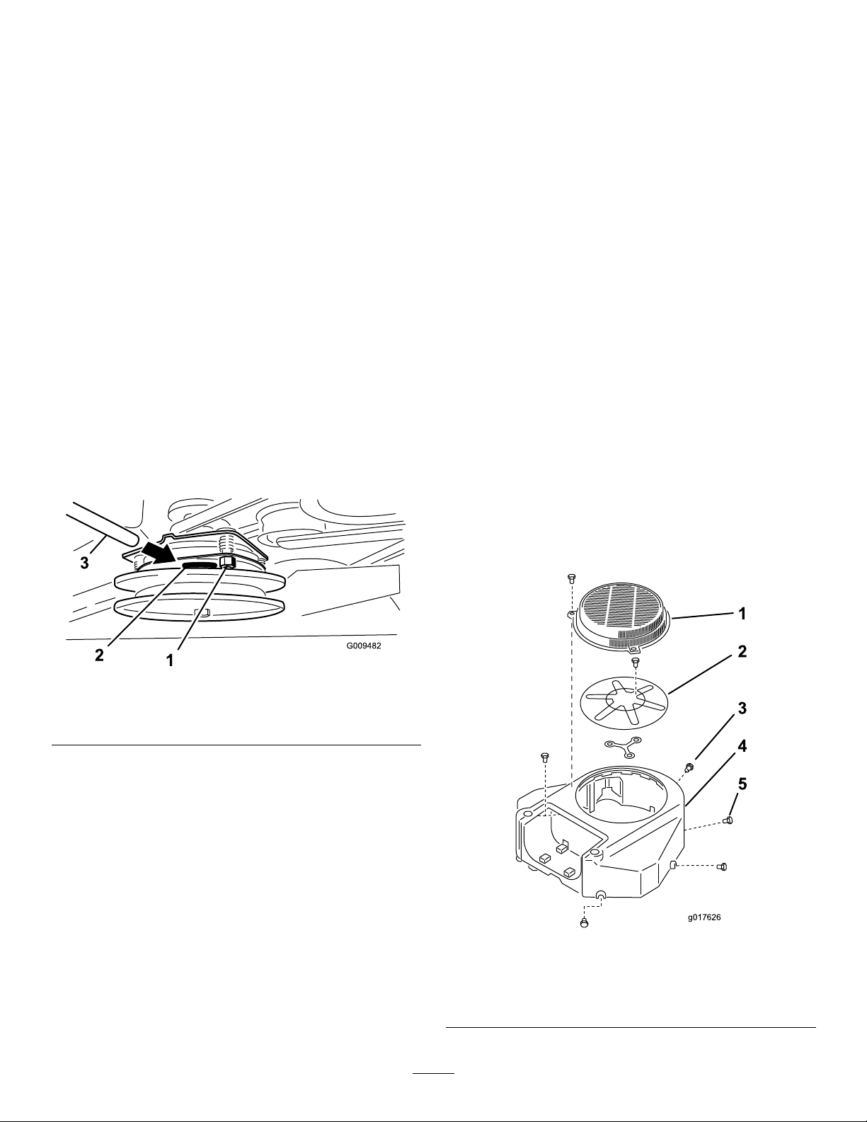
3.Removetheair-intakescreenandthefanhousing
(Figure61).
Figure60
1.Adjustingnut3.Feelergauge
2.Slot
4.Cleanthedebrisandgrassfromtheengineparts.
5.Installtheair-intakescreenandfanhousing(Figure61).
1.Guard
2.Engineair-intakescreen
3.Bolt
44
Figure61
4.Fanhousing
5.Screw

BrakeMaintenance
G021 180
4
ServicingtheBrake
Beforeeachuse,checkthebrakesonbothalevelsurfaceand
slope.
Alwayssettheparkingbrakewhenyoustopthemachine
orleaveitunattended.Iftheparkingbrakedoesnothold
securely,adjustit.
CheckingtheParkingBrake
ServiceInterval:Beforeeachuseordaily
Important:Ensurethatthemowerisonalevelsurface
whencheckingandadjustingthebrake.
1.Parkthemachineonalevelsurfaceanddisengagethe
PTO.
2.Shutofftheengine,removethekey ,andwaitforall
movingpartstostopbeforeleavingtheoperating
position.
3.Releasetheparkingbrake;refertoReleasingthe
ParkingBrake(page16).
4.Checkthetirepressure;refertoCheckingtheTire
Pressure(page43).
5.Withthebrakereleased,measurethedistancebetween
thebrakebarandthetireoneachside.
6.Usingthesidewiththesmallestclearance,ensurethat
thedistanceisbetween3and6mm(1/8and1/4
inches)asshowninFigure62);refertoAdjustingthe
Brakes(page46)whenadjustmentisneeded.
Figure62
1.Tire
2.Brakebar4.Measurethesmallest
3.Clearancebetween3and
6mm(1/8and1/4inches)
clearancebetweenthebar
andtire.
45

AdjustingtheBrakes
g013291
4
Ifthegapbetweenthebrakebarandtireisnotcorrect,adjust
thebrake.
1.Parkthemachineonalevelsurfaceanddisengagethe
PTO,andsettheparkingbrake.
2.Shutofftheengine,removethekey ,andwaitforall
movingpartstostopbeforeleavingtheoperating
position.
3.Releasetheparkingbrake;refertoReleasingthe
ParkingBrake(page16).
4.Toadjustthebrake,removetheclevispinandhairpin
cotterfromthelower-brakeleverandyoke(Figure63).
5.Adjusttheyoke(Figure62).
Note:Thedistancebetweenthebrakebarandthetire
needsbebetween3and6mm(1/8and1/4inches).
BeltMaintenance
CheckingtheBelts
ServiceInterval:Every100hours—Checkthepump-drive
belt.
Every100hours—Checkthemower-deckbelt(s).
Checkbeltsforcracks,frayededges,burnmarks,wear,signs
ofoverheatingoranyotherdamage.
Thesignsofawornmowerbeltaresquealingwhilethebelt
isrotating,bladesslippingwhileyouarecuttinggrass,frayed
beltedges,burnmarks,andcracks.Replacethemowerbeltif
youdetectanyofthesesigns.
ReplacingtheMower-Deck
Note:Totightenthebrake,rotatetheyokeup.To
loosenthebrake,rotatetheyokedown.
6.Checkthebrakeoperationagain;refertoCheckingthe
ParkingBrake(page45).
7.Securetheyoketothelower-brakeleverwiththeclevis
pinandhairpincotter(Figure63).
Belt
ForModelswitha91cmDeck
Important:Thefastenersonthecoversofthismachine
aredesignedtoremainonthecoverafterremoval.
Loosenallofthefastenersoneachcoverafewturns
sothatthecoverisloosebutstillattached,thengo
backandloosenthemuntilthecovercomesfree.This
preventsyoufromaccidentallystrippingtheboltsfree
oftheretainers.
1.DisengagethePTOandsettheparkingbrake.
2.Shutofftheengine,removethekey ,andwaitforall
movingpartstostopbeforeleavingtheoperating
position.
3.Loosentheboltsandremovetherightbeltcoverwith
theboltattachedtoit.
4.Removethespringfromtheanchorpostonthe
idler-pulleyarm(Figure64).
5.Removethewornmowerbelt(Figure64).
6.Installthenewmowerbeltaroundtheclutchpulley ,the
deckpulleys,andtheidlerpulley(Figure64).
7.Installthespringontotheanchorpostonthe
Figure63
1.Yoke3.Lower-brakelever
2.Clevispin
4.Hairpincotter
idler-pulleyarm(Figure64).
8.Installthebeltcoverontothemowerdeckandsecure
thebolt.
46

Figure64
1.Belt
2.Spring-loadedidlerpulley
3.Spring
ReplacingtheMower-Deck Belts
ForModelswitha102cmDeck
Important:Thefastenersonthecoversofthismachine
aredesignedtoremainonthecoverafterremoval.
Loosenallofthefastenersoneachcoverafewturns
sothatthecoverisloosebutstillattached,thengo
backandloosenthemuntilthecovercomesfree.This
preventsyoufromaccidentallystrippingtheboltsfree
oftheretainers.
ReplacingtheRightMower-DeckBelt
1.DisengagethePTOandsettheparkingbrake.
2.Shutofftheengine,removethekey ,andwaitforall
movingpartstostopbeforeleavingtheoperating
position.
3.Loosentheboltsandremovethebeltcoverswiththe
boltsattachedtothem.
4.Removethespringfromtheanchorpostonthe
idler-pulleyarm(Figure65).
5.Removethewornmowerbelt(Figure65).
6.Installthenewmowerbeltaroundthedeckpulleysand
idlerpulley(Figure65).
Figure65
1.Belt
2.Spring
3.Spring-loadedidlerpulley
ReplacingtheLeftMower-DeckBelt
1.DisengagethePTOandsettheparkingbrake.
2.Shutofftheengine,removethekey ,andwaitforall
movingpartstostopbeforeleavingtheoperating
position.
3.Loosentheboltsandremovethebeltcoverswiththe
boltsattachedtothem.
4.Toremovetheleftmowerbelt,therightmowerbelt
needstoberemovedrst;refertoReplacingtheRight
Mower-DeckBelt(page47).
5.Removethespringfromtheanchorpostonthe
idler-pulleyarm(Figure66).
6.Removethewornmowerbelt(Figure66).
7.Installthenewmowerbeltaroundthedeckpulleys,the
clutchpulley,andtheidlerpulley(Figure66).
8.Installthespringontotheanchorpost(Figure66).
9.Installtherightmowerbelt;refertoReplacingthe
RightMower-DeckBelt(page47).
10.Installthebeltcoversontothemowerdeckandsecure
thebolts.
7.Installthespringontotheanchorpostonthe
idler-pulleyarm(Figure65).
8.Installthebeltcoversontothemowerdeckandsecure
thebolts.
47

Figure66
G015402
1
2
3
5
4
6
1.Belt
2.Spring-loadedidlerpulley
3.Spring
ReplacingthePump-DriveBelt
ServiceInterval:Every100hours—Checkthepump-drive
belt.
1.DisengagethePTOandsettheparkingbrake.
2.Shutofftheengine,removethekey ,andwaitforall
movingpartstostopbeforeleavingtheoperating
position.
3.Removethemower-deckbelt.
4.Tiltthemachine;refertoRaisingtheMowerforAccess
(page30).
5.Removetheshoulderbolt,thenut,andthewasher
fromtheenginedeckandconnectedspring(Figure67).
Figure67
1.Hydraulicpumps
2.Idlerpulley5.Pump-drivebelt
3.Clutchpulley6.Shoulderbolt,nut,and
4.Clutchretainer
washer
6.Removethepump-drivebelt(Figure67).
7.Installthenewbeltaroundtheclutchandthe2pump
pulleys.
8.Installthespringontotheshoulderboltandwasher,
andconnectittotheenginedeckwiththenut(Figure
67).
9.Lowerthemachinetotheoperatingposition.
10.Installthemower-deckbelt.
48

ControlsSystem
Maintenance
AdjustingtheMotion-Control HandlePositions
AdjustingtheRightMotion-Control
Lever
Ifthemotion-controlleversdonotalignhorizontally ,adjust
therightmotion-controllever.
Note:Adjustthehorizontalalignmentbeforethefrontto
backalignment.
1.DisengagethePTO,movetherightmotion-control
levertotheNEUTRALposition,andsettheparking
brake.
2.Shutofftheengine,removethekey ,andwaitforall
movingpartstostopbeforeleavingtheoperating
position.
3.Pushtherightmotion-controlleverdownoutofthe
NEUTRAL-LOCKposition(Figure68).
Figure69
1.Cam
7.Adjustthecamuntilitalignswiththeleft
motion-controlleverandtightenthenutforthecam.
2.Nut
4.Checkiftherightmotion-controlleveraligns
horizontallywiththeleftmotion-controllever(Figure
68).
Figure68
1.Leftmotion-controllever3.Checkthehorizontal
2.Rightmotion-controllever
intheNEUTRAL-LOCK
position
Note:Toadjusttherightmotion-controllever
horizontally,adjustthecam.
5.Releasethecushionfromtherearofthemachine.
6.Loosenthenutholdingthecam(Figure69).
alignmenthere.
4.Rightmotion-controllever
Note:Movingthecamclockwise(inthevertical
position)lowersthehandle,whilemovingit
counterclockwise(intheverticalposition)raisesthe
handle.
Important:Ensurethattheatportionofthe
camdoesnotgoaboveaverticalposition(rightor
left),oryoumaycausedamagetotheswitch.
AdjustingtheNeutralPositionforthe
Motion-ControlLevers
Important:Ensurethatthetrackingofthemower
iscorrectafteradjustingthemotion-controllevers.
Adjustingthetrackingandaligningthemotion-control
leversfronttobackisthesameprocedure(Figure70).
Note:Adjustthehorizontalalignmentbeforethefrontto
backalignment.
Ifthemotion-controlleversdonotalignfronttoback,or
therightsidecontrolleverdoesnotmoveeasilyintothe
NEUTRAL-LOCKposition,adjustmentisrequired.
1.Afteryounishthehorizontalalignment,check
thefront-to-backalignmentbyslightlypushingthe
motion-controlleversforwardtotakeupanyslackin
thelinkageforthecontrollevers(Figure70).
49

G012706
1
2
3
4
Figure70
3
g017848
1.Leftmotion-controllever
2.Rightmotion-controllever4.Alignthecontrollevers
3.Neutral-lockedposition
fronttoback
2.Ensurethattherightmotion-controllevermoveseasily
intotheNEUTRAL-LOCKposition.
Note:Turnthecableadjustmentclockwiseto
movethemotion-controlhandleforward.Turn
thecableadjustmentcounterclockwisetomovethe
motion-controlhandlerearward.
3.Rotatethecableadjustmentontherightsidewhen
adjustmentisneeded.
Note:Adjustthecableadjustmentinquarter-turn
increments.
4.Aftertherightmotion-controllevermoveseasily
intotheNEUTRAL-LOCKposition,adjusttheleft
motion-controllevertoalignitwiththeright
motion-controllever.
5.Checkforpropertracking;refertoAdjustingthe
Tracking(page41).
6.Installthecablelockontothecable-adjustingnutsto
securetheadjustment(Figure71).
1.Leftcableadjustment
2.Cablelock
Figure71
3.Rightcableadjustment
50

HydraulicSystem
G012005
4 1 3
2
Note:Ifrequired,adduidtothereservoiruntilitis
betweenthehotlevelandthecoldlevel.
Maintenance
ServicingtheHydraulic System
HydraulicFluidType:Toro
uidorMobil
HydraulicSystemFluidCapacity:2.0L(67oz)
Important:Usethespeciedoilorequivalent.Other
uidscouldcausesystemdamage.
®
115W -50syntheticmotoroil.
®
HYPR-OIL
CheckingtheHydraulicFluid
ServiceInterval:Aftertherst8hours
Every50hours
Note:Thebafeinsidethetankhas2levelsdependingif
theoiliswarmorcold.
1.Positionthemachineonalevelsurface.
2.Disengagethepowertakeoff(PTO)andshutoffthe
engine.
3.Waitforallmovingpartstostopbeforeleavingthe
operatingpositionandsettheparkingbrake.
4.Cleantheareaaroundthecapandthellerneckofthe
hydraulictank(Figure72).
™
500hydraulic
Note:Theuidlevelshouldbebelowthehotlevelof
thebafewhentheuidiswarm(Figure72).
9.Installthecaponthellerneck.
WARNING
Hydraulicuidescapingunderpressurecan
penetrateskinandcauseinjury.
•Ifhydraulicuidisinjectedintotheskin,
itmustbesurgicallyremovedwithinafew
hoursbyadoctorfamiliarwiththistype
ofinjury.Gangrenemayresultifthisis
notdone.
•Keepyourbodyandhandsawayfrom
pinholeleaksornozzlesthateject
high-pressurehydraulicuid.
•Usecardboardorpapertondhydraulic
leaks.
•Safelyrelieveallpressureinthehydraulic
systembeforeperforminganyworkonthe
hydraulicsystem.
•Makesurethatallhydraulic-uidhoses
areingoodcondition,andallthatthe
hydraulicconnectionsandttingsare
tightbeforeapplyingpressuretohydraulic
system.
Figure72
1.Cap3.Colduidlevel—full
2.Bafe4.Hotuidlevel—full
5.Removethecapfromthellerneck(Figure72).
Note:Lookinsidetochecktheuidlevelinthe
reservoir.
6.Adduidtothereservoiruntilitreachesthecoldlevel
ofthebafe.
7.Runthemachineatlowidlefor15minutestoallow
anyairtopurgeoutofthesystemandwarmtheuid;
refertoStartingandStoppingtheEngine(page19).
8.Checktheuidlevelwhiletheuidiswarm.
ReplacingtheHydraulicFluid
ServiceInterval:Every250hours—Changethehydraulic
uidwhenusingMobil
Every500hours—Changethehydraulicuidwhen
usingToro
®
HYPR-OIL
™
500hydraulicuid.
®
1oil.
WARNING
Hothydraulicuidcancausesevereburns.
Allowthehydraulicuidtocoolbeforeperforming
anymaintenancetothehydraulicsystem.
1.DisengagethePTOandsettheparkingbrake.
2.Shutofftheengineandwaitforallmovingpartsto
stopbeforeleavingtheoperatingposition.
3.Removehydraulicreservoircap.
4.Locatethefronthydraulichoseunderthehydraulic
tankandplaceadrainpanunderthetank(Figure73).
5.Loosenthehoseclampandmoveitdownthehose.
6.Removethefronthydraulichoseandallowtheuidto
runoutofthetank.
51

ReplacingtheHydraulicFilter
ServiceInterval:Aftertherst8hours
Every500hours/Yearly(whichevercomesrst)
WARNING
Hothydraulicuidcancausesevereburns.
Allowthehydraulicuidtocoolbeforeperforming
anymaintenancetothehydraulicsystem.
Figure73
1.Hydraulictank3.Fronthydraulichose
2.Hydrauliclter
7.Changethehydrauliclter;refertoReplacingthe
HydraulicFilter(page52).
8.Connectthehydraulichoseunderthetank.
9.Adduidtothetankuntilitreachesthecoldbafe
ofthetank.
Important:Usethespeciedoilorequivalent.
Otheruidscouldcausesystemdamage.
10.Installthehydraulic-tankcap.
11.Startengineandletrunforabout2minutestopurge
airfromthesystem.
12.Shutofftheengineandcheckforleaks.
Note:Ifoneorbothwheelsdonotdrive,referto
BleedingtheHydraulicSystem(page53).
13.Checktheleveloftheuidandadduid,ifrequired.
1.DisengagethePTOandsettheparkingbrake.
2.Shutofftheengineandwaitforallmovingpartsto
stopbeforeleavingtheoperatingposition.
Important:Donotsubstituteautomotiveoillter,
orseverehydraulicsystemdamagemayresult.
3.Locatethelterandplaceadrainpanunderthelter
(Figure74).
Figure74
1.Hydraulictank
2.Hydrauliclter
Important:Donotoverll.
4.Removetheoldlterandwipethelter-adaptergasket
surfaceclean(Figure75).
5.Applyathincoatofhydraulicuidtotherubbergasket
onthereplacementlter.
6.Installreplacementhydrauliclterontothelter
adapter.
7.Turntheoillterclockwiseuntiltherubbergasket
contactsthelteradapterandtightenthelteran
additional1/2turn(Figure75).
52

Figure75
1.Hydrauliclter
2.Gasket
3.Adapter
8.Cleanupanyspilleduid.
9.Checktheuidinthereservoirandadduidtothe
tankuntilitreachesthecoldbafeofthetank.
Important:Usethespeciedoilorequivalent.
Otheruidscouldcausesystemdamage.
CheckingtheHydraulicHoses
ServiceInterval:Every100hours
Checkthehydraulichosesforleaks,loosettings,kinks,loose
mountingsupports,wear,generalweathering,andchemical
deterioration.Makeanynecessaryrepairsbeforeoperating.
Note:Keepareasaroundthehydraulicsystemcleanfrom
grassanddebrisbuildup.
Note:Extendedoperatingtimeathightemperaturesinahot
climatemayleadtodeteriorationofhosesandseals.Inspect
morefrequentlyinahotclimate,andchangethehydraulic
uidandltermorefrequently.
10.Starttheengineandletitrunforabout2minutesto
purgeairfromthesystem.
11.Shutofftheengineandcheckforleaks.
Note:Ifoneorbothwheelsdonotdrive,referto
BleedingtheHydraulicSystem(page53).
12.Checktheuidlevelandadduid,ifrequired.
Important:Donotoverll.
BleedingtheHydraulicSystem
Thetractionsystemisself-bleeding,however,itmaybe
necessarytobleedthesystemifuidischangedorafterwork
isperformedonthesystem.
1.DisengagethePTOandsettheparkingbrake.
2.Shutofftheengineandwaitforallmovingpartsto
stopbeforeleavingtheoperatingposition.
3.Raisetherearofthemachineontojackstandshigh
enoughtoraisethedrivewheelsofftheground.
4.Starttheengineandmovethethrottlecontroltothe
idleposition.
Note:Ifthedrivewheeldoesnotrotate,itispossible
toassistthepurgingofthesystembycarefullyrotating
thetireintheforwarddirection.
5.Checkthehydraulicuidlevelasitdrops,andadduid
asrequiredtomaintaintheproperlevel.
6.Repeatthisprocedurefortheoppositewheel.
53

MowerDeck Maintenance
ServicingtheCuttingBlades
Toensureasuperiorqualityofcut,keepthebladessharp.
Forconvenientsharpeningandreplacement,youmaywant
tokeepextrabladesonhand.
WARNING
Awornordamagedbladecanbreak,andapiece
ofthebladecouldbethrownatyouorbystanders,
resultinginseriouspersonalinjuryordeath.
•Inspectthebladesperiodicallyforwearor
damage.
•Replaceawornordamagedblade.
BeforeInspectingorServicingthe
Blades
CheckingforBentBlades
1.DisengagethePTO,movethemotion-controlleversto
theNEUTRAL-LOCKposition,andsettheparkingbrake.
2.Shutofftheengine,removethekey ,andwaitforall
movingpartstostopbeforeleavingtheoperating
position.
3.Rotatethebladesuntiltheendsfaceforwardand
backward.
4.Measurefromalevelsurfacetothecuttingedge,
positionA,oftheblades(Figure77).
Parkthemachineonalevelsurface,disengagethebladesand
settheparkingbrake.TurntheignitionkeytoOFF.Remove
thekey,anddisconnectthesparkplugwiresfromthespark
plugs.
InspectingtheBlades
ServiceInterval:Beforeeachuseordaily
1.Inspectthecuttingedges(Figure76).
2.Iftheedgesarenotsharporhavenicks,removeand
sharpentheblade;refertoSharpeningtheBlades(page
55).
3.Inspecttheblades,especiallyinthecurvedarea.
4.Ifyounoticeanycracks,wear,oraslotforminginthis
area,immediatelyinstallanewblade(Figure76).
Figure77
1.Measureherefromblade
tohardsurface
5.Rotatetheoppositeendsofthebladesforward.
6.Measurefromalevelsurfacetothecuttingedgeofthe
bladesatthesamepositionasinstep4above.
Note:Thedifferencebetweenthedimensions
obtainedinsteps4and5mustnotexceed3mm
(1/8inch).
Note:Ifthisdimensionexceeds3mm(1/8inch),
replacetheblade.
2.PositionA
WARNING
Abladethatisbentordamagedcould
breakapartandcouldcriticallyinjureyouor
bystanders.
Figure76
1.Cuttingedge3.Wear/slotforming
2.Curvedarea4.Crack
•Alwaysreplaceabentordamagedblade
withanewblade.
•Donotleorcreatesharpnotchesinthe
edgesorsurfacesoftheblade.
54

RemovingtheBlades
Replacethebladesiftheyhitasolidobject,ifabladeisoutof
balance,orifabladeisbent.Toensureoptimumperformance
andcontinuedsafetyconformanceofthemachine,use
genuineT ororeplacementblades.Replacementbladesmade
byothermanufacturersmayresultinnonconformancewith
safetystandards.
1.Holdthebladeendusingaragorathicklypadded
glove.
2.Removethebladebolt,thecurvedwasher,andthe
bladefromthespindleshaft(Figure78).
2.Checkthebalanceofthebladebyputtingitonablade
balancer(Figure80).
Note:Ifthebladestaysinahorizontalposition,the
bladeisbalanced.
Figure80
1.Blade2.Balancer
3.Ifthebladeisnotbalanced,lesomemetalofftheend
ofthesailareaonly(Figure78).
4.Repeatthisprocedureuntilthebladeisbalanced.
InstallingtheBlades
1.Installthebladeontothespindleshaft(Figure81).
Important:Thecurvedpartoftheblademustbe
pointingupwardtowardtheinsideofthemowerto
ensurepropercutting .
Figure78
1.Sailareaoftheblade3.Curvedwasher
2.Blade4.Bladebolt
SharpeningtheBlades
1.Usealetosharpenthecuttingedgeatbothendsof
theblade(Figure79).
Note:Maintaintheoriginalangle.
Note:Thebladeretainsbalanceifthesameamount
ofmaterialisremovedfrombothcuttingedges.
2.Installthespringdiskandbladebolt(Figure81).
Note:Thespring-diskconemustbeinstalledtoward
thebolthead(Figure81).
3.Torquethebladeboltto115to150N∙m(85to
110ft-lb).
1.Sharpenattheoriginalangle
Figure79
Figure81
1.Sailareaoftheblade3.Springdisk
2.Blade4.Bladebolt
55

LevelingtheMowerDeck
1
2
3
2
4
g020801
5
6
7
88
9
PreparingtheMachine
1.Positionthemachineonaatsurface.
2.DisengagethePTO,movethemotion-controlleversto
theNEUTRAL-LOCKposition,andsettheparkingbrake.
3.Shutofftheengine,removethekey ,andwaitforall
movingpartstostopbeforeleavingtheoperating
position.
4.Checkthetirepressureofbothdrivetires;referto
CheckingtheTirePressure(page43).
5.Lowerthemowerdecktothe76mm(3inch)
height-of-cutposition.
Note:Theactualcuttingheightwillnotbeadjusted
untilthedeckhasbeenleveled;refertoMatchingthe
HeightofCut(page59).
6.Checkthedistancebetweentheswivels,measuringat
thecenteroftheswivels(center-to-centerlength)on
eachthreadedrod(Figure82).
Note:Ensurethatthelengthis49.5cm(19-1/2
inches)for91cm(36inch)mowerdecksand43.7cm
(17-3/16inches)for102cm(40inch)mowerdecks.
7.Loosenthejamnutsatthefrontswivel.
8.Usingthejamnuts,adjustthelengthofthethreaded
rodtoachievethecorrectdistance.
9.Tightenthejamnutsatthefrontswivel.
Figure82
1.Measurehereatthe
centeroftheswivels
(center-to-centerlength).
2.Swiveljamnuts
3.Frontswivel8.Yoke
4.Frontchain9.Upperchainbolt
5.Rearchain
6.Adjustmentbolt
7.Jamnut
10.Checkthedistancebetweentheyokeandthedeck
hangerarmateachyoke.
Note:Thisdistanceneedstobe11mm(7/16inch)as
showninFigure83.
11.Ifadjustmentisneeded,loosentheupperchainbolt
(Figure82).
12.Loosenthejamnutandadjusttheadjustmentboltto
achievethecorrectdistanceasshowninFigure83.
13.Tightenthejamnutandtheupperchainbolt.
56

5
1
2
3
4
g020807
Figure83
g020858
C
D
1.Adjustmentbolt4.Deckhangerarm
2.Jamnut5.Thedistanceneedstobe
11mm(7/16inch).
3.Yoke
AdjustingtheRightSideFront-to-Rear
MowerDeckPitch
1.Positiontherightbladefront-to-rear(Figure84).
2.MeasuretherightbladeattheClocation,fromalevel
surfacetothecuttingedgeofthebladetip,andrecord
thismeasurement(Figure84).
3.MeasuretherightbladeattheDlocation,fromalevel
surfacetothecuttingedgeofthebladetip,andrecord
thismeasurement(Figure84).
Note:Themowerbladeshouldbea6to10mm
(1/4to3/8inch)loweratpositionCthanatposition
D(Figure84).Ifitisnotcorrect,proceedtothe
followingsteps.
4.Loosenthejamnutsattherightandleftfrontswivels.
5.Usingtherightjamnuts,adjustthelengthoftheright
threadedrodtoachievethe6to10mm(1/4to3/8
inch)front-to-rearpitch.
6.Tightenthejamnutsattherightandleftfrontswivels.
Figure84
1.Measureherefromblade
tohardsurface.
2.MeasureatCandD.
57

MatchingtheRearoftheMowerDeck
g020859
B
D
g020860
C
A
LevelingtheFrontoftheMowerDeck
1.Positiontheleftandrightbladesfront-to-rear.
2.MeasuretheleftbladeattheBlocation,fromalevel
surfacetothecuttingedgeofthebladetip,andrecord
thismeasurement(Figure85).
3.MeasuretherightbladeattheDlocation,fromalevel
surfacetothecuttingedgeofthebladetip,andrecord
thismeasurement(Figure85).
Note:ThemeasurementatpositionBneedstobe
within3mm(1/8inch)ofthemeasurementatposition
D.(Figure85).Ifitisnotcorrect,proceedtothe
followingsteps.
4.Loosenthejamnutsattheleftfrontswivel.
5.Usingtheleftjamnuts,adjustthelengthoftheleft
handthreadedroduntillocationBmatcheslocationD.
6.Tightenthejamnutsattheleftfrontswivel.
1.Positiontheleftandrightbladesfront-to-rear.
2.Inspectthefrontchainsandensurethateachchain
hastension.
Note:Ifeitherchainisloose,adjustthethreadedrod
withtheloosechaintoachievetensiononthatchain.
3.MeasuretheleftbladeattheAlocation,fromalevel
surfacetothecuttingedgeofthebladetip,andrecord
thismeasurement(Figure86).
4.MeasuretherightbladeattheClocation,fromalevel
surfacetothecuttingedgeofthebladetip,andrecord
thismeasurement(Figure86).
Note:ThemeasurementbetweenlocationAandC
needstobewithin3mm(1/8inch).Ifitisnotcorrect,
proceedtothefollowingsteps.
5.Loosentheupperchainbolts(Figure82).
6.Loosenthejamnutsoneachyoke.
7.Adjusttheadjustmentboltsintheyokes,atlocationsA
andC,toachievethecorrectheight.
8.Tightenthejamnutsandupperchainbolts.
1.Measureherefromblade
tohardsurface
Figure85
2.MeasureatBandD
1.Measureherefromblade
tohardsurface.
Figure86
2.MeasureatAandC.
58

MatchingtheHeightofCut
g020808
1 2 3 1
g020703
1
4 3 2
AdjustingtheCompressionSpring
1.Lowerthemowertothe76mm(3inches)height-of-cut
position.
2.Positiontherightbladefront-to-rear.
3.MeasuretherightbladeatlocationC,fromalevel
surfacetothecuttingedgeofthebladetip,andrecord
thismeasurement(Figure86).
Note:ThemeasurementatlocationCneedstobe
withinan3mm(1/8inch)ofthe76mm(3inches)
height-of-cutsetting.Ifitisnotcorrect,proceedto
thefollowingsteps.
4.Loosenthejamnutsatbothendsoftheturnbuckle
(Figure87).
Note:Theendoftheturnbucklewiththegroove
machinedinithasleftthreads(Figure87).
5.Adjusttheturnbuckletoraiseorlowerthedeckheight
toachieve76mm(3inches)atlocationC.
6.Tightenthejamnutsatbothendsoftheturnbuckle.
7.Checkandensurethatthemower-deckliftleverlatches
intothetransportposition.
Note:Ifitdoesnotlatchintothetransportposition,
adjusttheturnbuckleuntilitlatchesintothetransport
position.
Note:Adjustingthecompressionspringaltershowmuch
thedeckoatsandhowmucheffortittakestoliftthedeck
whenusingtheheight-of-cuthandle.
•Morespringcompressionreducesthehandleliftforce
requiredandcausesthedecktooatmore.
•Lessspringcompressionincreasesthehandleliftforce
requiredandcausesthedecktooatless.
1.Raisethedeck-liftleverandlockitintothetransport
position.
2.Checkthelengthofthecompressionspring.
Note:Nominallengthis28.2cm(11-1/8inches)for
91cm(36inch)mowerdecksand25.7cm(10-1/8
inches)for102cm(40inch)mowerdecks(Figure88).
3.Adjustthisdistance,bylooseningthespring-jamnut
andturningthenutinfrontofeachspring(Figure88).
4.Lockthenutintopositionbytighteningthespring-jam
nut(Figure88).
8.Tightenthejamnuts.
1.Jamnut
2.Turnbuckle
Figure87
3.Grooveindicatingleft
Figure88
1.25.7cm(10-1/8inch)for
102cm(40inch)mower
decksand28.2cm(11-1/8
inch)for91cm(36inch)
mowerdecks
2.Springjamnut4.Compressionspring
threads
3.Frontnut
59

ReplacingtheGrassDeector
g015594
1
6 2
4
7
3
5
Cleaning
WARNING
Anuncovereddischargeopeningcouldallowthe
machinetothrowobjectsintheoperator'sor
bystander'sdirectionandresultinseriousinjury.
Also,contactwiththebladecouldoccur.
Donotoperatethemachineunlessyouinstall
acoverplate,amulchplate,grassdeector,or
bagger.
1.Removethelocknut,bolt,spring,andspacerholding
thedeectortothepivotbrackets(Figure89).
CleaningundertheMower
ServiceInterval:Beforeeachuseordaily
Removethegrassbuildupunderthemowerdaily.
1.DisengagethePTO,movethemotion-controlleversto
theNEUTRAL-LOCKpositionandsettheparkingbrake.
2.Shutofftheengine,removethekey ,andwaitforall
movingpartstostopbeforeleavingtheoperating
position.
3.Raisethefrontofthemachineandusejackstandsto
supportthemower.
DisposingofWaste
Engineoil,batteries,hydraulicuid,andenginecoolantare
pollutantstotheenvironment.Disposeoftheseaccordingto
yourstateandlocalregulations.
Figure89
1.Bolt
2.Spacer6.Grassdeector
3.Locknut
4.Spring
2.Removethedamagedorworngrassdeector.
3.Placethespacerandthespringontothegrassdeector.
4.Place1J-hookendofthespringbehindthedeckedge.
Note:Makesurethat1J-hookendofspringis
installedbehinddeckedgebeforeinstallingtheboltas
showninFigure89.
5.Installtheboltandthenut.
6.Place1J-hookendofthespringaroundthegrass
deector(Figure89).
Important:Thegrassdeectormustbeable
torotate.Liftthedeectoruptothefullopen
position,andensurethatitrotatesintothefull
downposition.
5.Spring(installed)
7.J-hookendofthespring
60

Storage
CleaningandStorage
1.Disengagethepowertakeoff(PTO),settheparking
brake,turntheignitionkeytooff,andremovethekey.
2.Removegrassclippings,dirt,andgrimefromthe
externalpartsoftheentiremachine,especiallythe
engine.
Important:Y oucanwashthemachinewithamild
detergentandwater.Donotpressurewashthe
machine.Avoidexcessiveuseofwater,especially
nearthedrivesystemandengine.Pressure
washingcanforcedirtandwaterintocriticalparts,
suchasspindlebearingsandelectricalswitches.
3.Checkthebrake;refertoServicingtheBrake(page45).
4.Servicetheaircleaner;refertoServicingtheAir
Cleaner(page34).
5.Greasethemachine;refertoLubrication(page32).
6.Changetheengineoil;refertoChangingtheEngine
Oil(page36).
7.Checkthetirepressure;refertoCheckingtheTire
Pressure(page43).
8.Forlong-termstorage:
A.Addstabilizer/conditioneradditivetofuelinthe
tank.
B.Runenginetodistributeconditionedfuelthrough
thefuelsystem(5minutes).
C.Stopengine,allowtocoolanddrainthefueltank;
refertoDrainingtheFuelTank(page38),or
operateengineuntilitstops.
D.Restartengineandrununtilitstops.Repeat,on
Chokeuntilenginewillnotrestart.
E.Disposeoffuelproperly.Recycleasperlocal
codes.
Note:Donotstoregasolinewith
stabilizer/conditionerover90days.
9.Removethesparkplug(s)andcheckitscondition;refer
toServicingtheSparkPlug(page37).Withthespark
plug(s)removedfromtheengine,pourtwotablespoons
ofengineoilintothesparkplughole.Nowusethe
startertocranktheengineanddistributetheoilinside
thecylinder.Installthesparkplug(s).Donotinstallthe
wireonthesparkplug(s).
10.Checkandtightenallbolts,nuts,andscrews.Repairor
replaceanypartthatisdamagedordefective.
11.Paintallscratchedorbaremetalsurfaces.Paintis
availablefromyourAuthorizedServiceDealer.
12.Storethemachineinaclean,drygarageorstoragearea.
Removethekeyfromtheignitionswitchandkeepit
inamemorableplace.Coverthemachinetoprotect
itandkeepitclean.
61

Troubleshooting
Problem
Theenginedoesnotstart,startshard,or
failstokeeprunning.
Theenginelosespower.
PossibleCauseCorrectiveAction
1.Thefueltankisemptyortheshutoff
valveisclosed.
2.Thechokeisnoton.
3.Asparkplugwireislooseor
disconnected.
4.Asparkplugispitted,fouled,orthe
gapisincorrect.
5.Theaircleanerisdirty.
6.Dirtisinthefuellter.6.Replacethefuellter.
7.Dirt,water,orstalefuelisinthefuel
system.
8.Thegapbetweenthesafety-interlock
switchesisnotcorrect.
1.Theengineloadisexcessive.1.Reducethegroundspeed.
2.Theaircleanerisdirty.
3.Theoillevelinthecrankcaseislow.3.Addoiltothecrankcase.
4.Thecoolingnsandairpassages
undertheengineblowerhousingare
plugged.
5.Asparkplugispitted,fouled,orthe
gapisincorrect.
6.Theventholeinthefuelcapisplugged.6.Cleanorreplacethefuelcap.
7.Dirtisinthefuellter.7.Replacethefuellter.
8.Dirt,water,orstalefuelisinthefuel
system.
1.Fillthefueltankwithgasolineand
openthevalve
2.MovethechokelevertotheCHOKE
position.
3.Installthewireonsparkplug.
4.Installanew,correctlygappedspark
plug.
5.Servicetheaircleanerelement.
7.ContactanAuthorizedServiceDealer.
8.ContactanAuthorizedServiceDealer.
2.Servicetheaircleanerelement.
4.Removetheobstructionfromthe
coolingnsandairpassages.
5.Installanew,correctlygappedspark
plug.
8.ContactanAuthorizedServiceDealer.
Theengineoverheats.
Themachinedoesnotdrive.
Thereisabnormalvibration.
1.Engineloadisexcessive.1.Reducethegroundspeed.
2.Oillevelinthecrankcaseislow.
3.Coolingnsandairpassagesunder
theengineblowerhousingareplugged.
1.Thehydraulic-oilreservoirislow.
2.Airisinthehydraulicsystem.2.Bleedtheairoutthehydraulicsystem.
3.Apump-drivebeltslips.3.Replacethepumpdrivebelt.
4.Apump-drivebeltidlerspringis
missing.
5.Pumpbypassvalvesareopen.5.Tightenthebypassvalves.T orqueto
1.Cuttingblade(s)is/arebentor
unbalanced.
2.Ablade-mountingboltisloose.2.Tightentheblademountingbolt.
3.Enginemountingboltsareloose.3.Tightentheenginemountingbolts.
4.Anenginepulley ,idlerpulley ,orblade
pulleyisloose.
5.Anenginepulleyisdamaged.
6.Abladespindleisbent.
2.Addoiltothecrankcase.
3.Removetheobstructionfromthe
coolingnsandairpassages.
1.Addhydraulicuidtothereservoir.
4.Replacethepumpdrivebeltidler
spring.
12to15N∙m(9to11ft-lb).
1.Installnewcuttingblade(s).
4.Tightentheappropriatepulley .
5.ContactanAuthorizedServiceDealer.
6.ContactanAuthorizedServiceDealer.
62

Problem
PossibleCauseCorrectiveAction
Thecuttingheightisuneven.
Thebladesdonotrotate.
1.Blade(s)arenotsharp.1.Sharpentheblade(s).
2.Cuttingblade(s)is/arebent.2.Installnewcuttingblade(s).
3.Themowerdeckisnotlevel.3.Levelthemowerdeckside-to-side
4.Themowerdeckpitchiswrong.
5.Theundersideofmowerdeckisdirty.5.Cleantheundersideofthemower
6.Thetirepressureisnotcorrect.6.Adjustthetirepressure.
7.Abladespindleisbent.
1.Apumpdrivebeltisworn,looseor
broken.
2.Apumpdrivebeltisoffpulley.
3.Amowerdeckbeltisworn,looseor
broken.
4.Amowerdeckbeltisoffpulley.
5.Anidlerspringisbrokenormissing.5.Replacethespring.
6.Theelectricclutchisoutofadjustment.
7.Theclutchconnectororwireis
damaged.
8.Theelectricclutchisdamaged.
9.Thesafety-interlocksystemprevents
bladerotation.
10.ThePTOswitchisfaulty.10.ContactanAuthorizedServiceDealer.
position.
4.Adjustthefront-to-rearpitch.
deck.
7.ContactanAuthorizedServiceDealer.
1.Checkthebelttension.
2.Installdrivebeltandcheckadjusting
shaftsandbeltguidesforcorrect
position.
3.Installnewdeckbelt.
4.Installdeckpulleyandchecktheidler
pulley,idlerarmandspringforcorrect
positionandfunction.
6.Adjusttheclutchairgap.
7.ContactanAuthorizedServiceDealer.
8.ContactanAuthorizedServiceDealer.
9.ContactanAuthorizedServiceDealer.
63

Schematics
HydraulicSchematic(Rev .A)
64

G015606
ElectricalSchematic(Rev .A)
65

Notes:
66

InternationalDistributorList
Distributor:
AgrolancKft
AsianAmericanIndustrial(AAI)
B-RayCorporation
BrisaGoodsLLC
CascoSalesCompany
CeresS.A.CostaRica
CSSCTurfEquipment(pvt)Ltd.SriLanka
CyrilJohnston&Co.
CyrilJohnston&Co.RepublicofIreland
FatDragon
FemcoS.A.Guatemala
FIVEMANSNew-T echCo.,LtdChina
ForGarderOU
G.Y .K.CompanyLtd.
GeomechanikiofAthensGreece
GolfinternationalTurizm
HakoGroundandGardenSweden
HakoGroundandGarden
HayterLimited(U.K.)
HydroturfInt.CoDubai
HydroturfEgyptLLC
IrrimacPortugal351212388260T oroEuropeNVBelgium3214562960
IrrigationProductsInt'lPvtLtd.India00914424494387ValtechMorocco212537663636
JeanHeybroekb.v.Netherlands31306394611VictusEmakPoland48618238369
Country:
Hungary3627539640
HongKong85224977804
Korea82325512076
Mexico12104952417
PuertoRico7877888383
NorthernIreland442890813121
China
Estonia3723846060
Japan81726325861Riversa
Turkey902163365993
Norway4722907760
UnitedKingdom441279723444
UnitedArabEmirates97143479479T-MarktLogisticsLtd.Hungary3626525500
Egypt2025194308ToroAustraliaAustralia61395807355
PhoneNumber:Distributor:
MaquiverS.A.Colombia
MaruyamaMfg.Co.Inc.
Mountelda.s.CzechRepublic
Mountelda.s.Slovakia
5062391138
94112746100
442890813121ParklandProductsLtd.NewZealand6433493760
8861080841322
5024423277
86-10-63816136
30109350054
4635100000
MunditolS.A.
NormaGarden
OslingerTurfEquipmentSA
OyHakoGroundandGardenAb
Perfetto
PratoverdeSRL.
Prochaska&Cie
RTCohen2004Ltd.
LelyTurfcare
Lely(U.K.)Limited
SolvertS.A.S.
SpyprosStavrinidesLimitedCyprus
SurgeSystemsIndiaLimited
Country:
Japan81332522285
Argentina541 148219999
Russia749541 16120
Ecuador59342396970
Finland35898700733
Poland48618208416
Italy390499128128
Austria4312785100
Israel97298617979
Spain
Denmark4566109200
UnitedKingdom441480226800
France33130817700
India911292299901
PhoneNumber:
5712364079
420255704220
420255704220
34952837500
35722434131
EuropeanPrivacyNotice
TheInformationT oroCollects
ToroWarrantyCompany(T oro)respectsyourprivacy.Inordertoprocessyourwarrantyclaimandcontactyouintheeventofaproductrecall,weaskyou
tosharecertainpersonalinformationwithus,eitherdirectlyorthroughyourlocalT orocompanyordealer.
TheT orowarrantysystemishostedonserverslocatedwithintheUnitedStateswhereprivacylawmaynotprovidethesameprotectionasapplies
inyourcountry .
BYSHARINGYOURPERSONALINFORMATIONWITHUS,YOUARECONSENTINGTOTHEPROCESSINGOFYOURPERSONALINFORMATION
ASDESCRIBEDINTHISPRIV ACYNOTICE.
TheWayT oroUsesInformation
Toromayuseyourpersonalinformationtoprocesswarrantyclaims,tocontactyouintheeventofaproductrecallandforanyotherpurposewhichwetell
youabout.ToromayshareyourinformationwithT oro'safliates,dealersorotherbusinesspartnersinconnectionwithanyoftheseactivities.Wewillnot
sellyourpersonalinformationtoanyothercompany.Wereservetherighttodisclosepersonalinformationinordertocomplywithapplicablelawsand
withrequestsbytheappropriateauthorities,tooperateoursystemsproperlyorforourownprotectionorthatofotherusers.
RetentionofyourPersonalInformation
Wewillkeepyourpersonalinformationaslongasweneeditforthepurposesforwhichitwasoriginallycollectedorforotherlegitimatepurposes
(suchasregulatorycompliance),orasrequiredbyapplicablelaw .
Toro'sCommitmenttoSecurityofY ourPersonalInformation
Wetakereasonableprecautionsinordertoprotectthesecurityofyourpersonalinformation.Wealsotakestepstomaintaintheaccuracyandcurrent
statusofpersonalinformation.
AccessandCorrectionofyourPersonalInformation
Ifyouwouldliketorevieworcorrectyourpersonalinformation,pleasecontactusbyemailatlegal@toro.com.
AustralianConsumerLaw
AustraliancustomerswillnddetailsrelatingtotheAustralianConsumerLaweitherinsidetheboxoratyourlocalT oroDealer.
374-0269RevK

TheT oroWarranty
Landscape
Contractor
Equipment(LCE)
ConditionsandProductsCovered
TheT oroCompanyanditsafliate,ToroWarrantyCompany,pursuanttoan
agreementbetweenthem,jointlypromisetotheoriginalpurchasertorepair
theT oroProductslistedbelowifdefectiveinmaterialsorworkmanship.
Thefollowingtimeperiodsapplyfromthedateofpurchase:
ProductsWarrantyPeriod
WalkBehindMowers
53cmMowers–Residentialuse
53cmMowers–Commercialuse
76cmMowers–Residentialuse
76cmMowers–Commercialuse
Mid-SizeWalk-BehindMowers
•Engine2years
GrandStand
®
Mowers
•Engine2years
ZMaster
®
2000SeriesMowers
•Engine2years
ZMaster
®
3000SeriesMowers
•Engine2years
ZMaster
®
5000and6000Series
Mowers
•Engine2years
ZMaster
®
7000SeriesMowers
•Engine2years
AllMowers
•Battery2years
•Attachments2years
1
Residentialusemeansuseoftheproductonthesamelotasyourhome.Useatmorethanone
locationisconsideredcommercialuseandthecommercialwarrantywouldapply.
2
SomeenginesusedonT oroLCEProductsarewarrantedbytheenginemanufacturer .
3
Whicheveroccursrst.
Thiswarrantyincludesthecostofpartsandlabor,butyoumustpay
transportationcosts.
1
2years
1year
1
2years
1year
2years
5yearsor1,200hours
4yearsor500hours
5yearsor1,200hours
5yearsor1,200hours
5yearsor1,200hours
2
3
3
2
3
2
3
2
3
2
InstructionsforObtainingWarrantyService
IfyouthinkthatyourToroProductcontainsadefectinmaterialsor
workmanship,followthisprocedure:
1.Contactyoursellertoarrangeserviceoftheproduct.Ifforanyreason
itisimpossibleforyoutocontactyourseller,youmaycontactany
ToroAuthorizedDistributortoarrangeservice.
2.Bringtheproductandyourproofofpurchase(salesreceipt)tothe
ServiceDealer.
3.IfforanyreasonyouaredissatisedwiththeServiceDealer’s
analysisorwiththeassistanceprovided,contactusat:
ToroWarrantyCompany
811 1LyndaleAvenueSouth
Bloomington,MN55420-1196
001-952-948-4707
SeeattachedDistributorList.
OwnerResponsibilities
YoumustmaintainyourToroProductbyfollowingthemaintenance
proceduresdescribedintheOperator'sManual.Suchroutinemaintenance,
whetherperformedbyadealerorbyyou,isatyourexpense.
ItemsandConditionsNotCovered
Thereisnootherexpresswarrantyexceptforspecialemissionsystem
coverageandenginewarrantycoverageonsomeproducts.Thisexpress
warrantydoesnotcoverthefollowing:
•Costofregularmaintenanceserviceorparts,suchaslters,fuel,
lubricants,oilchanges,sparkplugs,airltersbladesharpeningorworn
blades,cable/linkageadjustments,orbrakeandclutchadjustments
•Componentsfailingduetonormalwear
•Anyproductorpartwhichhasbeenalteredormisusedorneglected
orrequiresreplacementorrepairduetoaccidentsorlackofproper
maintenance
•Pickupanddeliverycharges
•RepairsorattemptedrepairsbyanyoneotherthananAuthorizedT oro
ServiceDealer
•Repairsnecessaryduetofailuretofollowrecommendedfuel
procedure(consultOperator'sManualformoredetails)
–Removingcontaminantsfromthefuelsystemisnotcovered
–Useofoldfuel(morethanonemonthold)orfuelwhichcontains
morethan10%ethanolormorethat15%MTBE
–Failuretodrainthefuelsystempriortoanyperiodofnon-use
overonemonth
GeneralConditions
Thepurchaseriscoveredbythenationallawsofeachcountry.Therights
towhichthepurchaserisentitledwiththesupportoftheselawsarenot
restrictedbythiswarranty.
374-0272RevD
 Loading...