

Toro GrandStand 74504, GrandStand 74505, GrandStand 79504, GrandStand 79505 Operator's Manual
Page 1
FormNo.3403-282RevB
GrandStand
®
Mower
With48inor52inTURBOFORCE
Unit
ModelNo.74504—SerialNo.316000001andUp
ModelNo.74505—SerialNo.316000001andUp
ModelNo.79504—SerialNo.316000001andUp
ModelNo.79505—SerialNo.316000001andUp
®
Cutting
Registeratwww.T oro.com.
OriginalInstructions(EN)
*3403-282*B
Page 2
WARNING
CALIFORNIA
Proposition65Warning
Thisproductcontainsachemicalorchemicals
knowntotheStateofCaliforniatocausecancer,
birthdefects,orreproductiveharm.
Theengineexhaustfromthisproduct
containschemicalsknowntotheStateof
Californiatocausecancer,birthdefects,
orotherreproductiveharm.
ThissparkignitionsystemcomplieswithCanadianICES-002
ItisaviolationofCaliforniaPublicResourceCode
Section4442or4443touseoroperatetheengineonany
forest-covered,brush-covered,orgrass-coveredlandunless
theengineisequippedwithasparkarrester,asdenedin
Section4442,maintainedineffectiveworkingorderorthe
engineisconstructed,equipped,andmaintainedforthe
preventionofre.
YoumaycontactTorodirectlyatwww .Toro.comforproduct
safetyandoperationtrainingmaterials,accessoryinformation,
helpndingadealer,ortoregisteryourproduct.
Wheneveryouneedservice,genuineT oroparts,oradditional
information,contactanAuthorizedServiceDealerorToro
CustomerServiceandhavethemodelandserialnumbersof
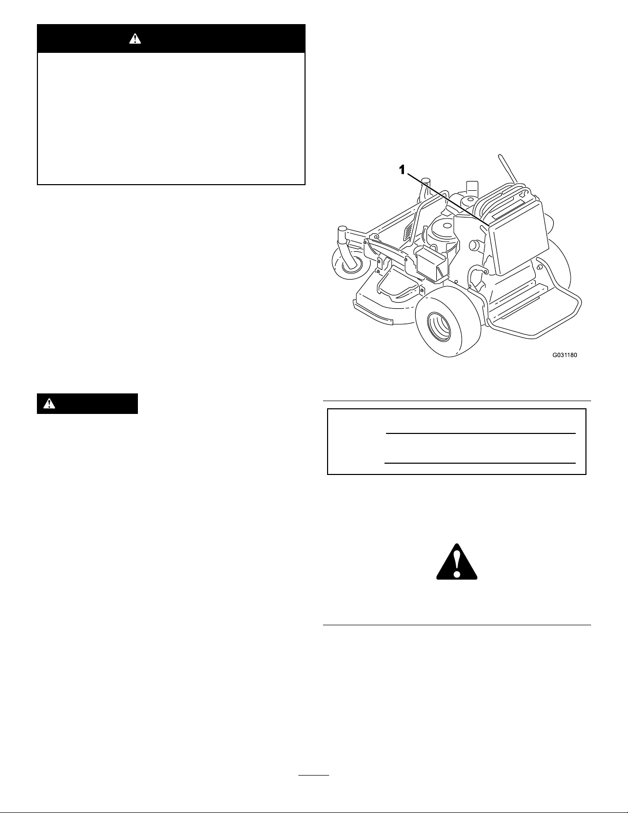
yourproductready.Figure1identiesthelocationofthe
modelandserialnumbersontheproduct.Writethenumbers
inthespaceprovided.
Theenclosed
informationregardingtheUSEnvironmentalProtection
Agency(EPA)andtheCaliforniaEmissionControl
Regulationofemissionsystems,maintenance,and
warranty.Replacementsmaybeorderedthroughthe
enginemanufacturer.
Engine Owner's Man ual
issuppliedfor
WARNING
Removingstandardoriginalequipmentpartsand
accessoriesmayalterthewarranty,traction,and
safetyofthemachine.FailuretouseoriginalT oro
partscouldcauseseriousinjuryordeath.Making
unauthorizedchangestotheengine,fuelorventing
system,mayviolateEPAandCARBregulations.
Replaceallpartsincluding,butnotlimitedto,tires,
belts,blades,andfuelsystemcomponentswith
originalToroparts.
Introduction
Figure1
1.Locationofthemodelandserialnumbers
ModelNo.
SerialNo.
Thismanualidentiespotentialhazardsandhassafety
messagesidentiedbythesafety-alertsymbol(Figure2),
whichsignalsahazardthatmaycauseseriousinjuryordeath
ifyoudonotfollowtherecommendedprecautions.
Figure2
1.Safety-alertsymbol
Thisrotaryblade,ride-onlawnmowerisintendedtobeused
byprofessional,hiredoperators,orresidentialhomeowners.
Itisdesignedprimarilyforcuttinggrassonwell-maintained
lawnsonresidentialorcommercialproperties.Itisnot
designedforcuttingbrushorforagriculturaluses.
Readthisinformationcarefullytolearnhowtooperateand
maintainyourproductproperlyandtoavoidinjuryand
productdamage.Youareresponsibleforoperatingthe
productproperlyandsafely.
©2016—TheToro®Company
8111LyndaleAvenueSouth
Bloomington,MN55420
Thismanualuses2wordstohighlightinformation.
Importantcallsattentiontospecialmechanicalinformation
andNoteemphasizesgeneralinformationworthyofspecial
attention.
Contactusatwww.Toro.com.
2
PrintedintheUSA
AllRightsReserved
Page 3

Contents
Safety...........................................................................4
SafeOperatingPractices...........................................4
ToroMowerSafety..................................................6
SlopeIndicator.......................................................7
SafetyandInstructionalDecals.................................8
ProductOverview.........................................................12
Controls...............................................................12
Specications........................................................13
Operation....................................................................14
ThinkSafetyFirst...................................................14
AddingFuel...........................................................14
CheckingtheEngine-OilLevel.................................15
BreakinginaNewMachine......................................15
OperatingtheParkingBrake....................................15
OperatingtheMower-Blade-ControlSwitch
(PTO)...............................................................16
OperatingtheThrottle............................................16
OperatingtheChoke..............................................16
OperatingtheIgnitionSwitch..................................17
UsingtheFuel-ShutoffValve...................................17
StartingandShuttingofftheEngine..........................18
TheSafety-InterlockSystem....................................19
OperatingthePlatform...........................................19
DrivingForwardorBackward..................................20
StoppingtheMachine.............................................21
PushingtheMachinebyHand..................................22
TransportingtheMachine........................................22
LoadingtheMachine..............................................22
SideDischargingorMulchingtheGrass.....................24
AdjustingtheHeight-of-Cut....................................24
AdjustingtheFlowBafe........................................25
PositioningtheFlowBafe......................................25
UsingtheMid-SizeWeight.......................................26
Maintenance.................................................................27
RecommendedMaintenanceSchedule(s)......................27
PremaintenanceProcedures........................................28
ReleasingtheCushionforRearAccess.......................28
Lubrication...............................................................28
GreasingtheT orsionIdler.......................................28
GreasingtheFrontCasterPivots..............................29
GreasingtheCaster-WheelHubs..............................29
EngineMaintenance..................................................30
ServicingtheAirCleaner.........................................30
ServicingtheEngineOil..........................................31
ServicingtheSparkPlug..........................................33
CheckingtheSparkArrester.....................................34
FuelSystemMaintenance...........................................35
DrainingtheFuelTank...........................................35
RemovingtheFuelTank..........................................35
ServicingtheFuelFilter..........................................36
ElectricalSystemMaintenance....................................36
ServicingtheBattery...............................................36
ServicingtheFuses.................................................38
DriveSystemMaintenance.........................................39
AdjustingtheTracking............................................39
CheckingtheTirePressure......................................39
AdjustingtheCaster-PivotBearing............................40
ServicingtheCasterWheelsandBearings...................40
UsingtheClutchShim............................................41
CheckingtheWheel-LugNuts..................................42
CheckingtheWheel-HubNuts.................................42
CoolingSystemMaintenance......................................43
CleaningtheAir-IntakeScreen.................................43
CleaningtheCoolingSystem....................................43
BrakeMaintenance....................................................43
ServicingtheBrake.................................................43
BeltMaintenance......................................................44
ReplacingtheMower-DeckBelt...............................44
ReplacingtheTransmissionBelt..............................44
ControlsSystemMaintenance.....................................45
AdjustingtheMotion-ControlLevers........................45
HydraulicSystemMaintenance....................................46
ServicingtheHydraulicSystem.................................46
MowerDeckMaintenance...........................................48
ServicingtheCuttingBlades.....................................48
CorrectingtheMowerQualityofCut........................50
AdjustingtheDeck-LiftSpring.................................53
ReplacingtheGrassDeector..................................53
Cleaning...................................................................54
CleaningundertheMower.......................................54
DisposingoftheWaste............................................54
Storage........................................................................54
CleaningandStorage..............................................54
Troubleshooting...........................................................56
Schematics...................................................................58
3
Page 4

Safety
Improperuseormaintenancebytheoperatororowner
canresultininjury.Toreducethepotentialforinjury,
complywiththesesafetyinstructions,andpayattentionto
thesafetyalertsymbol,whichmeansCaution,Warning,or
Danger—personalsafetyinstruction.Failuretocomplywith
theinstructionsmayresultinpersonalinjuryordeath.
Thismachinewasmanufacturedaccordingtotheappropriate
regulatorystandardsineffectatthetimeofmanufacture.
Modifyingthismachineinanywaymaycauseittobeoutof
compliancewiththosestandardsandwiththeinstructionsin
thisOperator’ sManual.Modicationstothismachineshould
onlybemadebyeitherthemanufactureroranAuthorized
ToroDealer.
Thisproductiscapableofamputatinghandsandfeet.Follow
allsafetyinstructionstoavoidseriousinjuryordeath.
Theowner/usercanpreventandisresponsibleforaccidents
orinjuriesoccurringtopeople,ordamagetoproperty.
Theadditionofattachmentsmadebyothermanufacturers
thatdonotmeetAmericanNationalStandardsInstitute
certicationmaycausenoncomplianceofthismachine.
SafeOperatingPractices
ThefollowinginstructionsarefromANSIstandard
B71.4-2012.
Training
•ReadtheOperator'sManualandothertrainingmaterial.If
theoperator(s)ormechanic(s)cannotreadthemanual
language,itistheowner'sresponsibilitytoexplainthis
materialtothem.
•Becomefamiliarwiththesafeoperationoftheequipment,
operatorcontrols,andsafetysigns.
•Alloperatorsandmechanicsshouldbetrained.The
ownerisresponsiblefortrainingtheusers.
•Neverletchildrenoruntrainedpeopleoperateorservice
theequipment.Localregulationsmayrestricttheageof
theoperator.
•Theowner/usercanpreventandisresponsiblefor
accidentsorinjuriesoccurringtohimselforherself,other
people,ordamagetoproperty.
Preparation
•Evaluatetheterraintodeterminewhataccessoriesand
attachmentsyouneedtoproperlyandsafelyperformthe
job.Useonlyaccessoriesandattachmentsapprovedby
themanufacturer.
•Wearappropriateclothing;includingsafetyglasses,long
pants,substantialslip-resistantfootwear,gloves,and
hearingprotection.Tiebacklonghair.Donotwear
jewelry.
•Inspecttheareawhereyouwillusetheequipmentand
ensurethatallobjectsareremovedfromtheareabefore
use.
•Useextracarewhenhandlingfuels.Theyareammable
andvaporsareexplosive.
–Useonlyanapprovedcontainer.
–Donotremovethefuelcaporaddfuelwiththe
enginerunning.Allowtheenginetocoolbefore
refueling.Donotsmokenearthemachinewhenthe
engineisrunning.
–Donotrefuelordrainthemachineindoors.
•Checkthattheoperator'spresencecontrols,safety
switches,andshieldsareattachedandfunctioning
properly.Donotoperatethemachineunlesstheyare
functioningproperly.
Operation
•Lightningcancausesevereinjuryordeath.Iflightning
isseen,orthunderisheardinthearea,donotoperate
themachine;seekshelter.
•Donotrunanengineinanenclosedarea.
•Operateonlyinwell-litareas,keepingawayfromholes
andhiddenhazards.
•Ensurethatalldrivesareinneutralandthattheparking
brakeisengagedbeforestartingengine.Starttheengine
onlyfromtheoperator’ sposition.
•Makesurethatyouhavegoodfootingwhileusingthis
machine,especiallywhenbackingup.Reducedfooting
couldcauseslipping.
•Slowdownanduseextracareonhillsides.Besureto
travelsidetosideonhillsides.Turfconditionscanaffect
thestabilityofthemachine.Usecautionwhileoperating
neardrop-offs.
•Slowdownandusecautionwhenmakingturnsandwhen
changingdirectionsonslopes.
•Donotraisethemowerdeckwiththebladesrunning.
•DonotoperatethemachinewithoutthePTOshieldor
otherguardssecurelyinplace.Besurethatallinterlocks
areattached,adjustedproperly,andfunctioningproperly.
•Donotoperatewiththedischargedeectorraised,
removedoraltered,unlessyouareusingagrasscatcher.
•Donotchangetheenginegovernorsettingoroverspeed
theengine.
4
Page 5

•Stoponlevelground,disengagedrives,engagethe
parkingbrake,shutofftheenginebeforeleavingthe
operator'spositionforanyreason,includingemptyingthe
catchersoruncloggingthechute.
•Stopequipmentandinspectthebladesafterstriking
objectsorifanabnormalvibrationoccurs.Makethe
necessaryrepairsbeforeresumingoperations.
•Keepyourhandsandfeetawayfromthecuttingunit.
•Lookbehindanddownbeforebackinguptoensurea
clearpath.
•Keeppetsandbystandersawayfromanoperating
machine.
•Slowdownandusecautionwhenmakingturnsand
crossingroadsandsidewalks.Stopthebladesifyouare
notmowing.
•Beawareofthemower-dischargedirectionanddonot
pointitatanyone.
•Donotoperatethemachinewhiletired,ill,orunderthe
inuenceofalcoholordrugs.
•Usecarewhenloadingorunloadingthemachineinto
orfromatrailerortruck.
Hauling
•Usecarewhenloadingorunloadingthemachineintoa
traileroratruck.
•Usefull-widthrampsforloadingmachineintoatrailer
oratruck.
•Tiethemachinedownsecurelyusingstraps,chains,cable,
orropes.Bothfrontandrearstrapsshouldbedirected
downandoutwardfromthemachine.
•Usecarewhenapproachingblindcorners,shrubs,trees,
orotherobjectsthatmayobscurevision.
MaintenanceandStorage
•Disengagedrives,settheparkingbrake,shutoffthe
engine,andremovethekeyordisconnectspark-plugwire.
Waitforallmovementtostopbeforeadjusting,cleaning,
orrepairing.
•Cleangrassanddebrisfromthecuttingunit,drives,
mufers,andenginetohelppreventres.
•Cleanupoilorfuelspills.
•Lettheenginecoolbeforestoringthemachine.
•Donotstorefuelnearamesordrainthefuelindoors.
•Donotallowuntrainedpersonneltoservicethemachine.
•Usejackstandstosupportcomponentswhenrequired.
•Carefullyreleasepressurefromcomponentswithstored
energy.
•Disconnectthebatteryorremovethespark-plugwire
beforemakinganyrepairs.Disconnectthenegative
terminalrstandthepositiveterminallast.Connectthe
positiveterminalrstandnegativelast.
•Usecarewhencheckingtheblades.Wraptheblade(s)or
weargloves,andusecautionwhenservicingthem.Only
replaceblades;donotstraightenorweldthem.
•Keephandsandfeetawayfrommovingparts.Ifpossible,
donotmakeadjustmentswiththeenginerunning.
•Keepallpartsingoodworkingconditionandallhardware
tightened.Replaceallwornordamageddecals.
5
Page 6

ToroMowerSafety
SlopeOperation
ThefollowinglistcontainssafetyinformationspecictoToro
productsandothersafetyinformationthatyoumustknow.
Thisproductiscapableofamputatinghandsandfeetand
ofthrowingobjects.Alwaysfollowallsafetyinstructionsto
avoidseriousinjuryordeath.
Thisproductisdesignedforcuttingandrecyclinggrass,or,
whenequippedwithagrassbagger,forcatchingcutgrass.
Anyuseforpurposesotherthanthesecouldprovedangerous
totheuserandbystanders.
GeneralOperation
•Besurethattheareaisclearofbystandersbeforemowing.
Stopthemachineifanyoneentersthearea.
•Donottouchequipmentorattachmentpartswhichmay
behotfromoperation.Allowallofthepartstocool
beforeattemptingtomaintain,adjust,orservicethe
machine.
•UseonlyToro-approvedattachments.W arrantymaybe
voidedifusedwithanyunapprovedattachments.
•Checkcarefullyforoverheadclearances(i.e.,branches,
doorways,electricalwires,etc.)beforeoperatingunder
anyobjects,anddonotcontactthem.
•Slowdownbeforemakingturnsanduseextracaution.
Allslopesandrampsrequireextracaution.Ifyoufeeluneasy
onaslope,donotmowit.
•Removeobstaclessuchasrocks,treelimbs,etc.fromthe
mowingarea.
•Watchforholes,rutsorbumps.Tallgrasscanhide
obstacles.
•Usecautionneardrop-offs,ditches,orembankments.
Themachinecouldsuddenlyturnoverifawheelgoes
overtheedgeofaclifforditch,orifanedgecavesin.
•Useextracarewithgrasscatchersorotherattachments.
Thesecanchangethestabilityofthemachine.
•Keepallmovementonslopesslowandgradual.
•Donotmakesuddenchangesinspeedordirection.
•Mowslopessidetoside.
•Donotmowslopesgreaterthan20degrees.
Service
•Donotstorethemachineorafuelcontainerinsidewhere
thereisanopename,suchasnearawaterheateror
furnace.
•Keepthenutsandboltstight,especiallythe
blade-attachmentbolts.
•Usecautionwhenridingtheplatformovercurbs,rocks,
roots,orotherobstructions.
•Lookbehindanddownbeforebackinguptoensurea
clearpath.Useextracarewhenoperatingthemachine
inreverse.
•Donotjerkthecontrols;useasteadymotion.
•Whenloadingorunloadingthemachine,useone
full-widthrampthatiswideenoughtoextendbeyond
thewidthofthemachine.
•Donotcarrypassengers.
•Donotcarryequipmentonthemachine.
•Neverremoveortamperwithsafetydevices.Checktheir
properoperationregularly.Neverdoanythingtointerfere
withtheintendedfunctionofasafetydeviceortoreduce
theprotectionprovidedbyasafetydevice.
•Tobestprotectyourinvestmentandmaintainoptimal
performanceofyourToroequipment,countonToro
genuineparts.Whenitcomestoreliability,Torodelivers
replacementpartsdesignedtotheexactengineering
specicationsofourequipment.Forpeaceofmind,insist
onTorogenuineparts.
•Checktheoperationofthebrakesfrequently.Adjustand
servicethemasrequired.
6
Page 7
SlopeIndicator
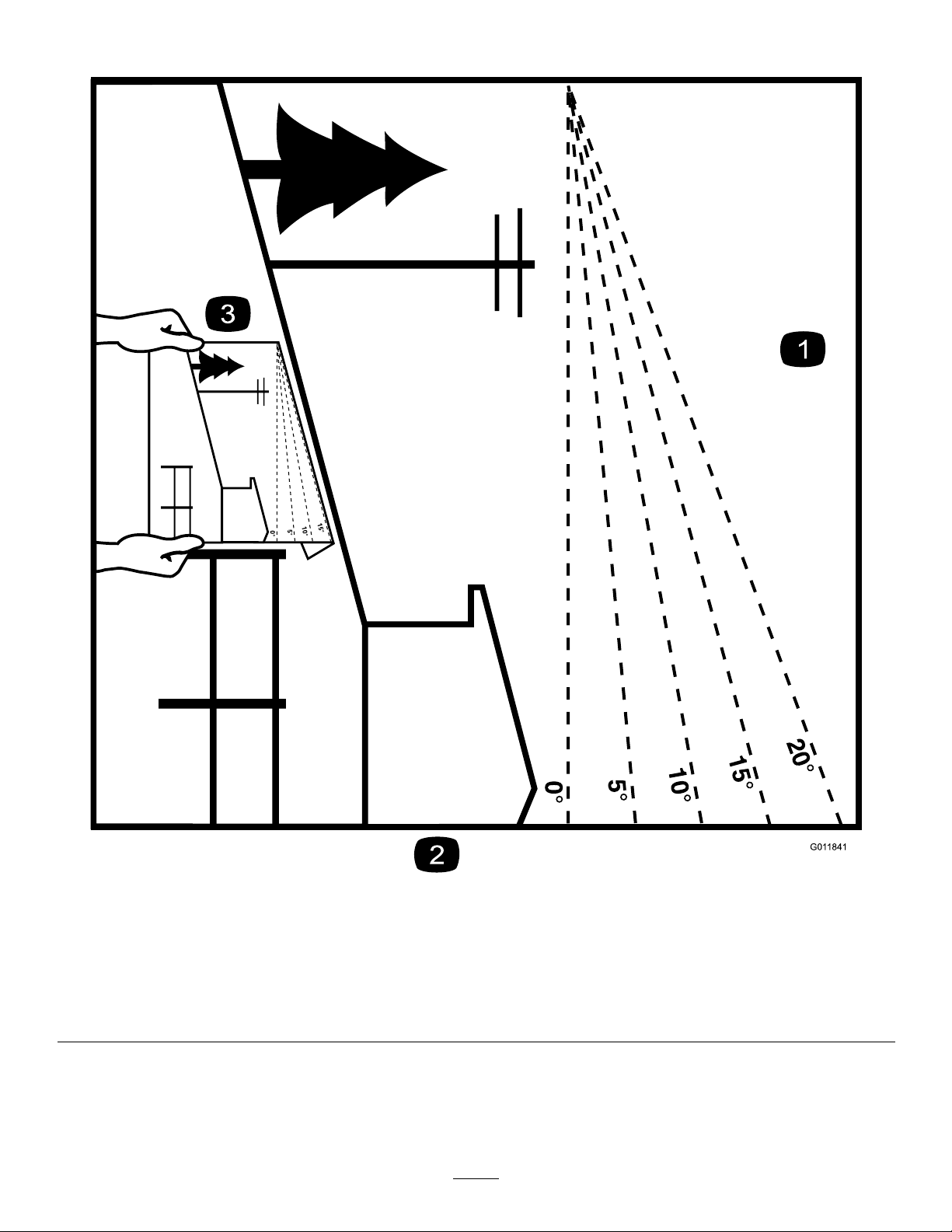
G011841
Figure3
Thispagemaybecopiedforpersonaluse.
1.Themaximumslopeyoucansafelyoperatethemachineonis20degrees.Usetheslopecharttodeterminethedegreeofslope
ofhillsbeforeoperating.Donotoperatethismachineonaslopegreaterthan20degrees.Foldalongtheappropriateline
tomatchtherecommendedslope.
2.Alignthisedgewithaverticalsurface,atree,building,fencepole,etc.
3.Exampleofhowtocompareslopewithfoldededge
7
Page 8
SafetyandInstructionalDecals
Safetydecalsandinstructionsareeasilyvisibletotheoperatorandarelocatednearanyareaofpotential
danger.Replaceanydecalthatisdamagedorlost.
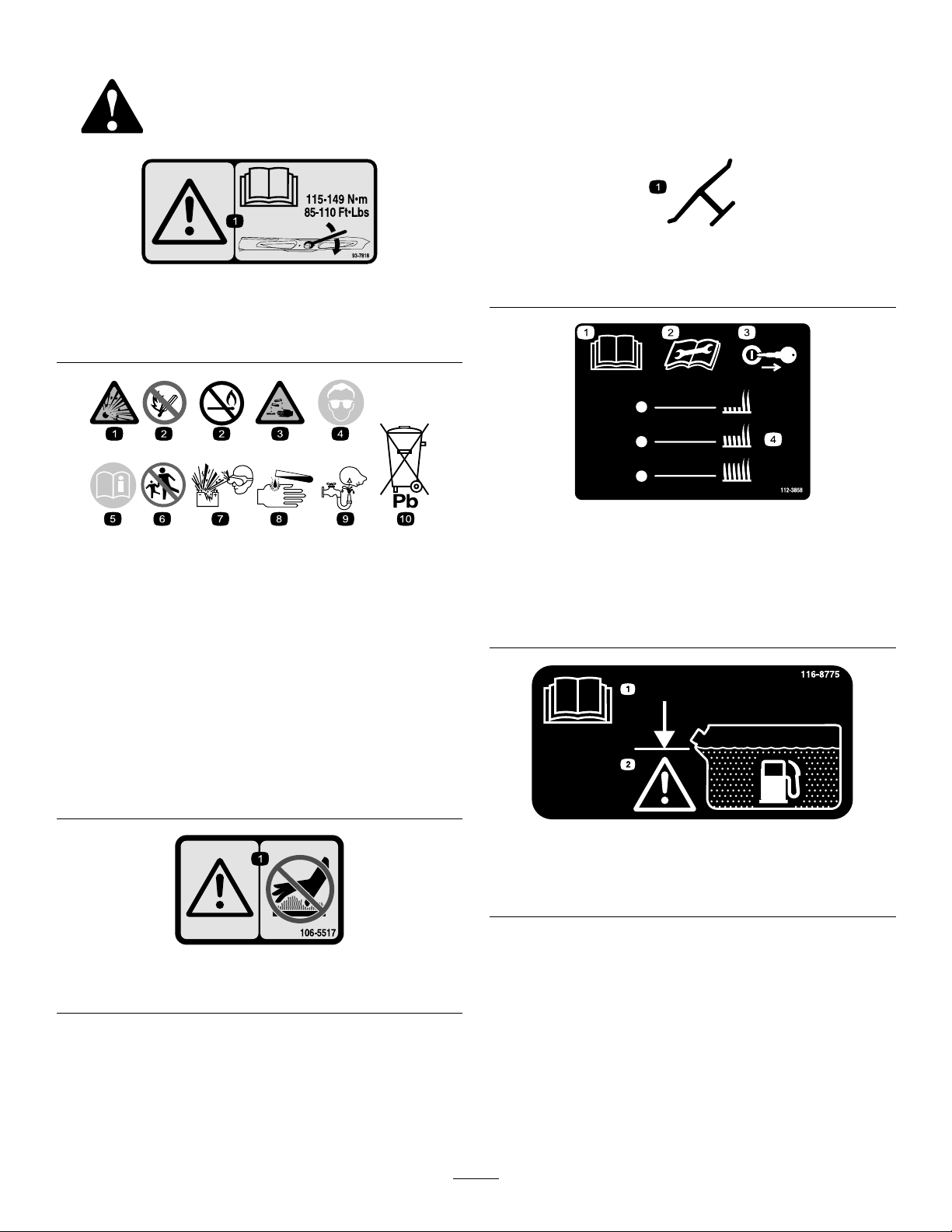
Manufacturer'sMark
93-7818
1.Warning—readtheOperator'sManualforinstructionson
torquingthebladebolt/nutto1 15to149N∙m(85to110
ft-lb).
BatterySymbols
Someorallofthesesymbolsareonyourbattery
1.Explosionhazard
2.Nore,opename,or
smoking.
3.Causticliquid/chemical
burnhazard
4.Weareyeprotection.9.Flusheyesimmediately
5.ReadtheOperator's
Manual.
6.Keepbystandersasafe
distancefromthebattery.
7.Weareyeprotection;
explosivegasescan
causeblindnessandother
injuries.
8.Batteryacidcancause
blindnessorsevereburns.
withwaterandgetmedical
helpfast.
10.Containslead;donot
discard.
1.Indicatesthebladeisidentiedasapartfromtheoriginal
machinemanufacturer.
112-3858
1.ReadtheOperator's
Manual.
2.Readtheinstructions
beforeservicingor
performingmaintenance.
3.Removetheignitionkey
beforeadjustingtheheight
ofcut.
4.Height-of-cutsettings.
1.Warning—donottouchthehotsurface.
116-8775
1.ReadtheOperator’s
Manual.
2.Filltobottomofllerneck;
warning—donotoverll
thetank.
106-5517
8
Page 9
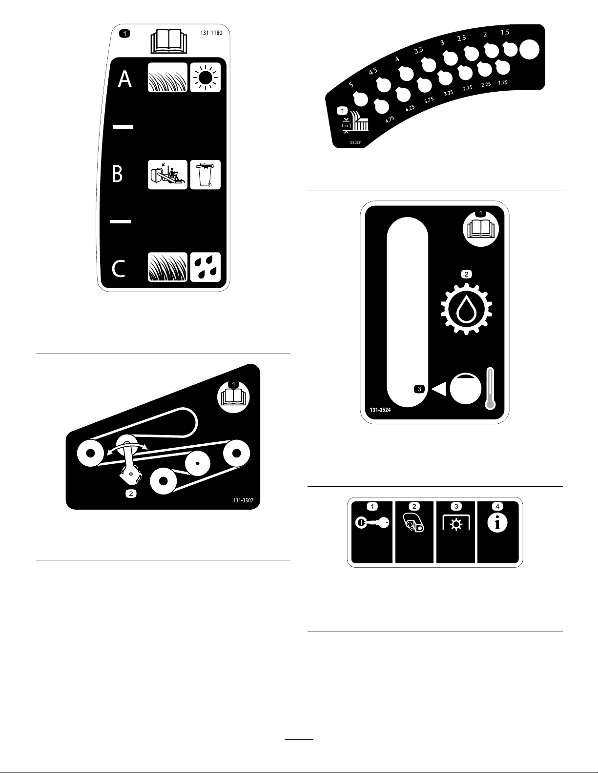
131-1180
131-3528
15A 15A 10A
7.5A
1.ReadtheOperator'sManual.(A)Short,lightgrass;dry
conditions;maximumdispersion;(B)Baggingsetting;(C)
Tall,densegrass;wetconditions;maximumgroundspeed
131-3521
1.Height-of-cut
131-3524
1.ReadtheOperator's
Manual.
1.ReadtheOperator's
Manual.
2.Transmissionoil
3.Oillevel
131-3507
2.Belttensioner
131-3528
1.Ignition—15A
2.Accessoryport—15A
3.Powertakeoff(PTO)—10
A
4.Infocenter—7.5A
9
Page 10
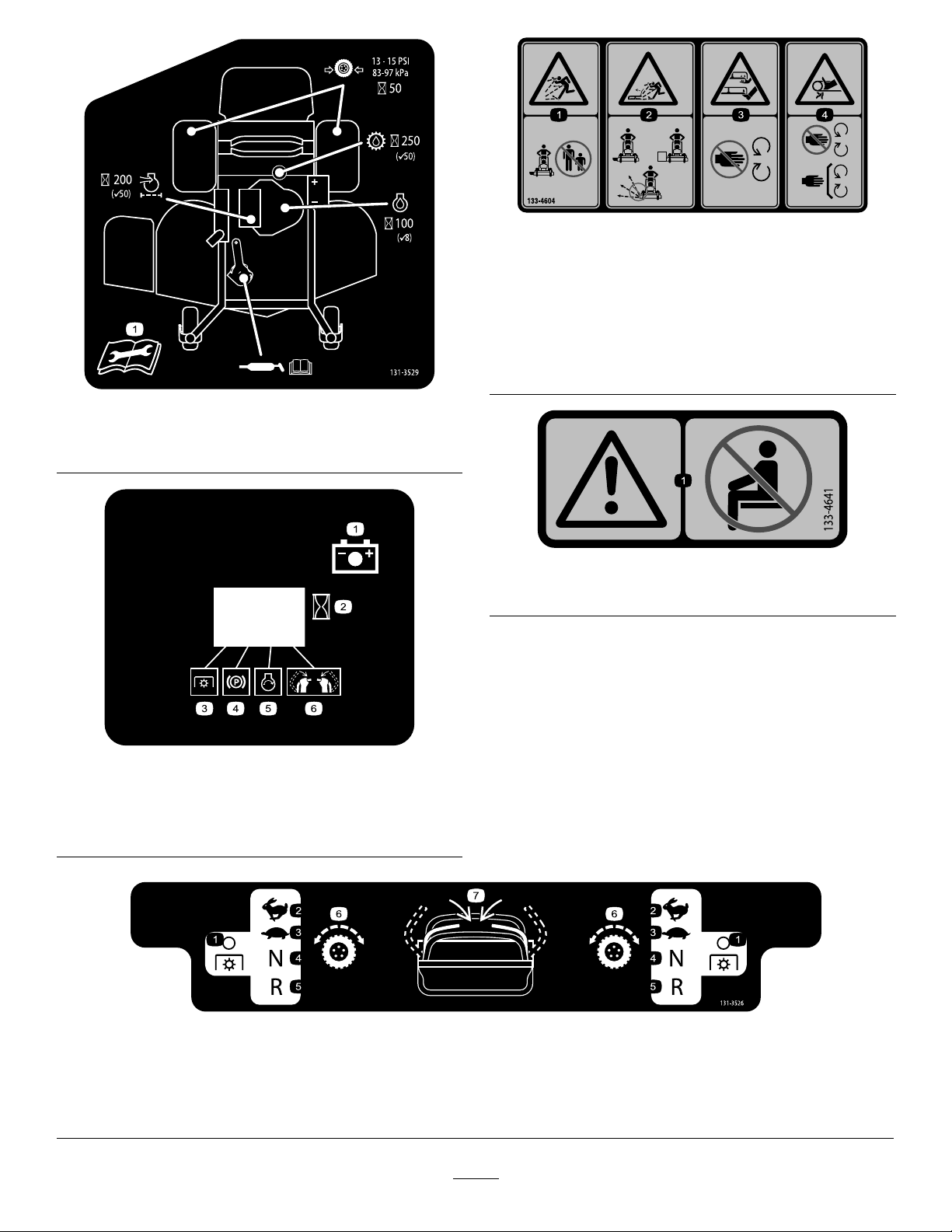
133-4604
131-3529
1.ReadtheOperator'sManualformoreinformationon
maintenanceintervalsandprocedures.
1.Thrownobject
hazard—keepbystanders
awayfromthemachine.
2.Thrownobjecthazard,
openbafe—onlyoperate
themachinewithabafe
oragrasscollector.
1.Warning—donotcarryanypassengers.
3.Severinghazardofhand
orfoot—keepawayfrom
movingparts.
4.Entanglement
hazard—keepaway
frommovingparts;keep
allguardsandshieldsin
place.
133-4641
131-3536
1.Battery4.Parkingbrake
2.Time5.Engine—start
3.Powertakeoff(PTO)
6.Engagethehandlebars.
131-3526
1.Powertakeoff(PTO)—disengaged
2.Fast6.Tractiondrive
3.Slow
4.Neutral
5.Reverse
7.Engagethehandles.
10
Page 11
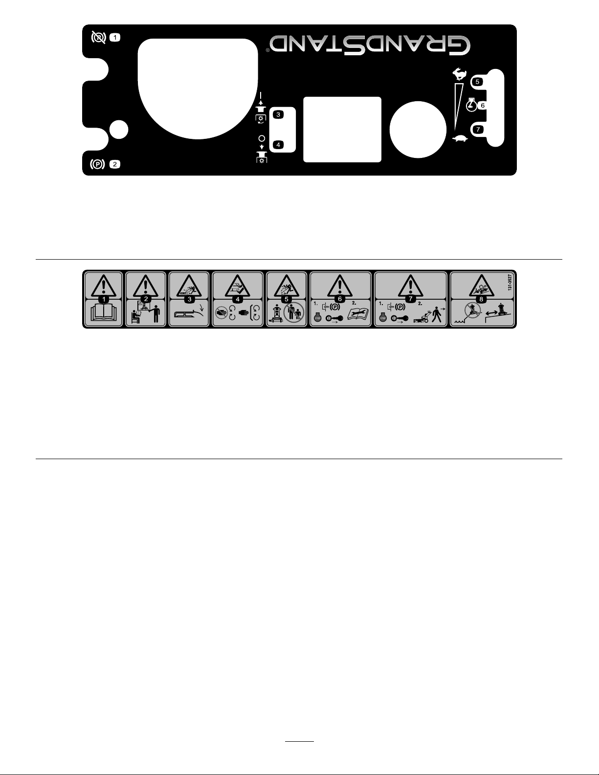
131-3525
1.Disengagetheparkingbrake.5.Fast
2.Engagetheparkingbrake.6.Engine—speed
3.EngagethePTO.7.Slow
4.DisengagethePTO.
131-3527
1.Warning—readtheOperator'sManual.5.Thrownobjecthazard—keepbystandersawayfromthe
2.Warning—receivetrainingbeforeoperatingthemachine.6.Warning—1)Engagetheparkingbrake,shutofftheengine,
3.Thrownobjecthazard—keepthedeectorloweredduring
operation.
4.Cutting/severinghazardofhandorfoot—keepawayfrom
movingparts;keepallguardsandshieldsinplace.
machine.
andremovethekeyfromtheignition;2)ReadtheOperator's
Manualbeforeservicingorperformingmaintenance.
7.Warning—engagetheparkingbrake,shutofftheengine,and
removethekeyfromtheignitionbeforeleavingthemachine.
8.Tippinghazard—donotoperateneardrop-offsornearwater.
11
Page 12
ProductOverview
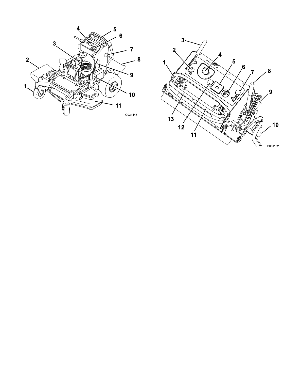
Figure4
1.Frontcasterwheel7.Fueltank
2.Side-dischargechute8.Platform(downposition)
3.Engine
4.Controls
5.Controllevers
6.Hydraulictank
9.Fuel-shutoffvalve
10.Battery
11.Mowerdeck
Controls
Becomefamiliarwithallthecontrols(Figure5)beforeyou
starttheengineandoperatethemachine.
Figure5
1.Fuelcap
2.Choke9.Height-of-cutpin
3.Parking-brakelever
4.Hydraulic-tankcap11.Rightmotion-controllever
5.Hourmeter12.Blade-controlswitch
6.Ignitionswitch
7.Throttlecontrol
8.Height-of-cutlever
10.Platformlatch
(PTO)
13.Leftmotion-controllever
HourMeter
Thehourmeterrecordsthenumberofhourstheenginehas
operated.Itoperateswhentheengineisrunning.Usethese
timesforschedulingregularmaintenance(Figure5).
Safety-InterlockIndicators
Symbolsonthehourmeterindicatewithablacktrianglethat
theinterlockcomponentisinthecorrectposition(Figure5).
Battery-IndicatorLight
IftheignitionkeyisturnedtotheONpositionforafew
seconds,thebatteryvoltagedisplaysintheareawherethe
hoursarenormallydisplayed.
Thebatterylightturnsonwhentheignitionisturnedonand
whenthechargeisbelowthecorrectoperatinglevel(Figure
5).
ThrottleControl
ThethrottlecontrolisvariablebetweentheFASTandSLOW
positions(Figure5).
12
Page 13

Choke
Specications
Usethechoketostartacoldengine(Figure5).
Blade-ControlSwitch(PTO)
Usetheblade-controlswitch(PTO)toengageanddisengage
themowerblades(Figure5).
IgnitionSwitch
Usetheignitionswitchtostartthemowerengine(Figure5).
Theswitchhas3positions:OFF,RUN,andSTART.
Motion-ControlLevers
Themotion-controlleversareusedtodrivethemachine
forwardandreverseandtoturneitherdirection(Figure5).
Fuel-ShutoffValve
Closethefuel-shutoffvalve(locatedontheleftsideofthe
fueltank)whentransportingorstoringthemower(Figure4).
Attachments/Accessories
AselectionofToroapprovedattachmentsandaccessoriesis
availableforusewiththemachinetoenhanceandexpand
itscapabilities.ContactyourAuthorizedServiceDealeror
Distributororgotowww .Toro.comforalistofallapproved
attachmentsandaccessories.
Note:Specicationsanddesignaresubjecttochange
withoutnotice.
48-inchMowers
Widthwithdeectordown163cm(64inches)
Widthwithdeectorraised127cm(50inches)
Lengthwithplatformdown191cm(75inches)
Lengthwithplatformup155cm(61inches)
Height
Weight
122cm(48inches)
408kg(899lb)
52-inchMowers
Widthwithdeectordown173cm(68inches)
Widthwithdeectorraised137cm(54inches)
Lengthwithplatformdown191cm(75inches)
Lengthwithplatformup155cm(61inches)
Height
Weight
122cm(48inches)
412kg(908lb)
13
Page 14

Operation
G009027
1
2
Note:Determinetheleftandrightsidesofthemachine
fromthenormaloperatingposition.
DANGER
Incertainconditions,gasolineisextremely
ammableandhighlyexplosive.Areorexplosion
fromgasolinecanburnyouandothersandcan
damageproperty.
ThinkSafetyFirst
Carefullyreadallthesafetyinstructionsanddecalsinthe
safetysection.Knowingthisinformationcouldhelpyouor
bystandersavoidinjury.
CAUTION
Thismachineproducessoundlevelsinexcessof
85dBAattheoperator'searandcancausehearing
lossfromextendedperiodsofexposure.
Wearhearingprotectionwhenoperatingthis
machine.
•Fillthefueltankoutdoors,inanopenarea,
whentheengineiscold.Wipeupanygasoline
thatspills.
•Neverllthefueltankinsideanenclosedtrailer.
•Donotllthefueltankcompletelyfull.Add
gasolinetothefueltankuntilthelevelis6to13
mm(1/4to1/2inch)belowthebottomofthe
llerneck.Thisemptyspaceinthetankallows
gasolinetoexpand.
•Neversmokewhenhandlinggasoline,andstay
awayfromanopenameorwheregasoline
fumesmaybeignitedbyaspark.
Useprotectiveequipmentforyoureyes,ears,andfeet.
•Storegasolineinanapprovedcontainerand
keepitoutofthereachofchildren.Neverbuy
morethana30-daysupplyofgasoline.
•Donotoperatewithoutentireexhaustsystemin
placeandinproperworkingcondition.
Figure6
1.Weareyeprotection.2.Wearhearingprotection.
DANGER
Incertainconditionsduringfueling,static
electricitycanbereleasedcausingaspark,which
canignitethegasolinevapors.Areorexplosion
AddingFuel
•Forbestresults,useonlyclean,fresh(lessthan30days
old),unleadedgasolinewithanoctaneratingof87or
higher((R+M)/2ratingmethod).
•Ethanol:Gasolinewithupto10%ethanol(gasohol)
or15%MTBE(methyltertiarybutylether)byvolume
isacceptable.EthanolandMTBEarenotthesame.
Gasolinewith15%ethanol(E15)byvolumeisnot
approvedforuse.Neverusegasolinethatcontains
morethan10%ethanolbyvolume,suchasE15
(contains15%ethanol),E20(contains20%ethanol),or
E85(containsupto85%ethanol).Usingunapproved
gasolinemaycauseperformanceproblemsand/orengine
damagewhichmaynotbecoveredunderwarranty.
•Donotusegasolinecontainingmethanol.
•Donotstorefueleitherinthefueltankorfuelcontainers
overthewinterunlessyouuseafuelstabilizer.
•Donotaddoiltogasoline.
fromgasolinecanburnyouandothersandcan
damageproperty.
•Alwaysplacegasolinecontainersontheground
awayfromyourvehiclebeforelling.
•Donotllgasolinecontainersinsideavehicleor
onatruckortrailerbedbecauseinteriorcarpets
orplastictruckbedlinersmayinsulatethe
containerandslowthelossofanystaticcharge.
•Whenpractical,removegas-poweredequipment
fromthetruckortrailerandrefueltheequipment
withitswheelsontheground.
•Ifthisisnotpossible,thenrefuelsuch
equipmentonatruckortrailerfromaportable
containerratherthanfromagasoline-dispenser
nozzle.
•Ifyoumustuseagasoline-dispensernozzle
mustbeused,keepthenozzleincontactwith
therimofthefueltankorcontaineropeningat
alltimesuntilfuelingiscomplete.
14
Page 15
WARNING
BreakinginaNewMachine
Gasolineisharmfulorfatalifswallowed.Long-term
exposuretovaporscancauseseriousinjuryand
illness.
•Avoidprolongedbreathingofvapors.
•Keepfaceawayfromnozzleandgastankor
conditionerbottleopening.
•Avoidcontactwithskin;washoffspillswith
soapandwater.
UsingStabilizer/Conditioner
Useafuelstabilizer/conditionerinthemachinetoprovide
thefollowingbenets:
•Keepsgasolinefreshduringstorageof90daysorless.
Forlongerstorage,drainthefueltank.
•Cleanstheenginewhileitruns
•Eliminatesgum-likevarnishbuildupinthefuelsystem,
whichcauseshardstarting
Important:Donotusefueladditivescontaining
methanolorethanol.
Addthecorrectamountofgasstabilizer/conditionerto
thegas.
Note:Afuelstabilizer/conditionerismosteffective
whenmixedwithfreshgasoline.Tominimizethechance
ofvarnishdepositsinthefuelsystem,usefuelstabilizer
atalltimes.
Newenginestaketimetodevelopfullpower.Mowerdecks
anddrivesystemshavehigherfrictionwhennew,placing
additionalloadontheengine.Allow40to50hoursof
break-intimefornewmachinestodevelopfullpowerand
bestperformance.
OperatingtheParkingBrake
Alwayssettheparkingbrakewhenyoustopthemachineor
leaveitunattended.Beforeeachuse,checktheparkingbrake
forproperoperation.
Iftheparkingbrakedoesnotholdsecurely,adjustit;referto
AdjustingtheBrakes(page43).
CAUTION
Childrenorbystandersmaybeinjuredifthey
moveorattempttooperatethemachinewhileitis
unattended.
Alwaysremovetheignitionkeyandsettheparking
brakewhenleavingthemachineunattended.
SettingtheParkingBrake
Pulltheparking-brakeleverrearwardintotheENGAGED
position(Figure7).
FillingtheFuelTank
1.Shuttheengineoffandsettheparkingbrake.
2.Cleanaroundthefuel-tankcapandremovethecap.
3.Addunleadedregulargasolinetothefueltank,until
thelevelis6to13mm(1/4to1/2inch)belowthe
bottomofthellerneck.
Note:Thisspaceinthetankallowsthegasolineto
expand.Donotllthefueltankcompletelyfull.
4.Installthefuel-tankcapsecurely.Wipeupanygasoline
thatmayhavespilled.
CheckingtheEngine-OilLevel
Beforeyoustarttheengineandusethemachine,check
theoillevelintheenginecrankcase;refertoCheckingthe
Engine-OilLevel(page31).
Figure7
1.Parkingbrake—engaged2.Parkingbrake—released
ReleasingtheParkingBrake
Pushtheparking-brakeleverforward(Figure7).
15
Page 16
Operatingthe
G009174
G008946
G008959
1
2
OperatingtheThrottle
Mower-Blade-ControlSwitch
(PTO)
Usetheblade-controlswitch(PTO)inconjunctionwiththe
motion-controlleverstoengageanddisengagethemower
blades.
EngagingtheMowerBlades(PTO)
Figure8
ThethrottlecontrolmovesbetweenFASTandSLOWpositions
(Figure11).
AlwaysusetheFASTpositionwhenengagingthemower
bladeswiththeblade-controlswitch(PTO).
Figure11
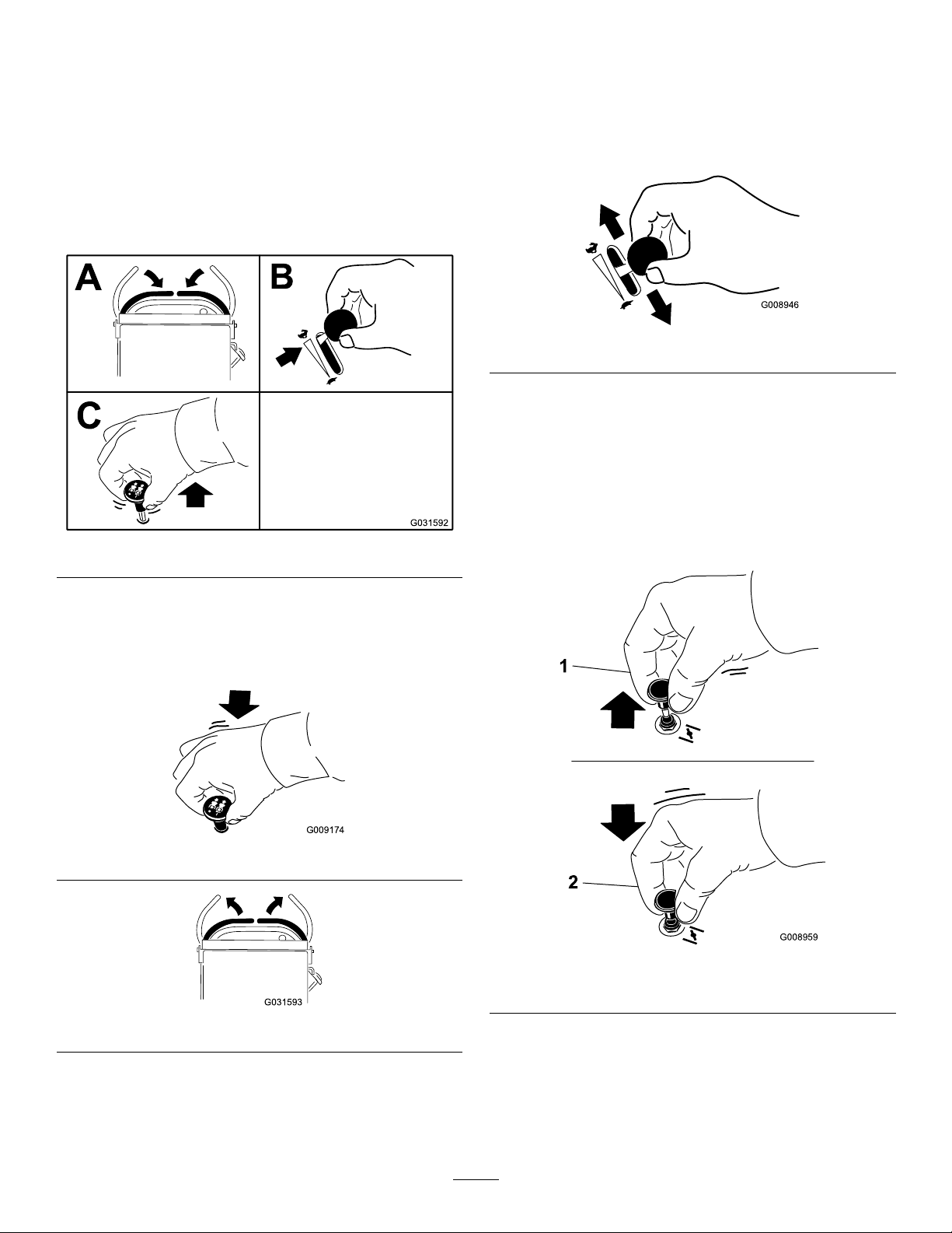
OperatingtheChoke
Usethechoketostartacoldengine.
1.Pullupthechokeknobtoengagethechokebefore
usingtheignitionswitch(Figure12).
2.Pushdownthechokeknobtodisengagethechoke
aftertheenginehasstarted(Figure12).
DisengagingtheMowerBlades(PTO)
Figure9andFigure10show2waystodisengagethemower
blades.
Figure9
1.Onposition2.Offposition
Figure10
Figure12
16
Page 17
OperatingtheIgnitionSwitch
UsingtheFuel-ShutoffValve
Important:Donotengagethestarterformorethan
5secondsatatime.Iftheenginefailstostart,wait
15secondsbetweenattempts.Failuretofollowthese
instructionscanburnoutthestartermotor.
Note:Youmayneedtorepeatthecycleforstartingthe
enginewhenyoustartitforthersttimeafteryouhavelled
acompletelyemptyfuelsystemwithfuel.
Figure13
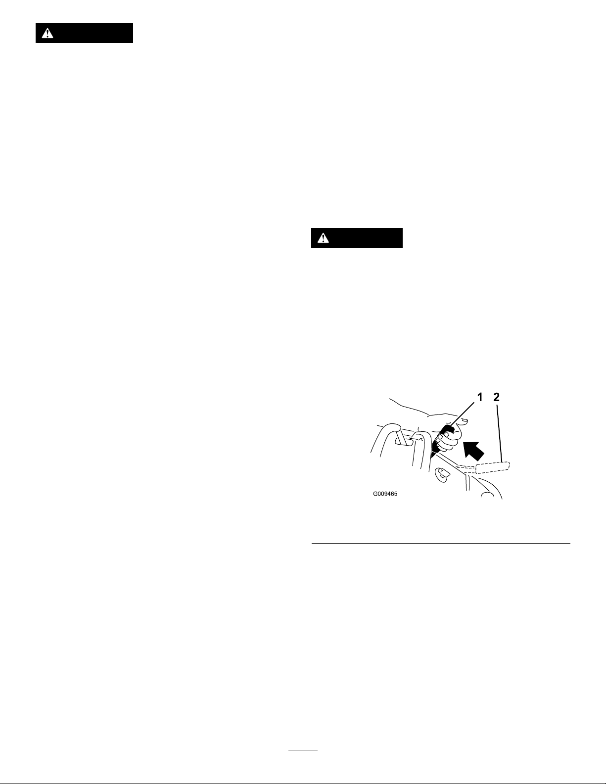
Closethefuel-shutoffvalvefortransport,maintenance,and
storage(Figure15).
Ensurethatthefuel-shutoffvalveisopenwhenstartingthe
engine.
Figure14
Figure15
1.ONposition2.OFFposition
17
Page 18
StartingandShuttingoffthe
ShuttingofftheEngine
Engine
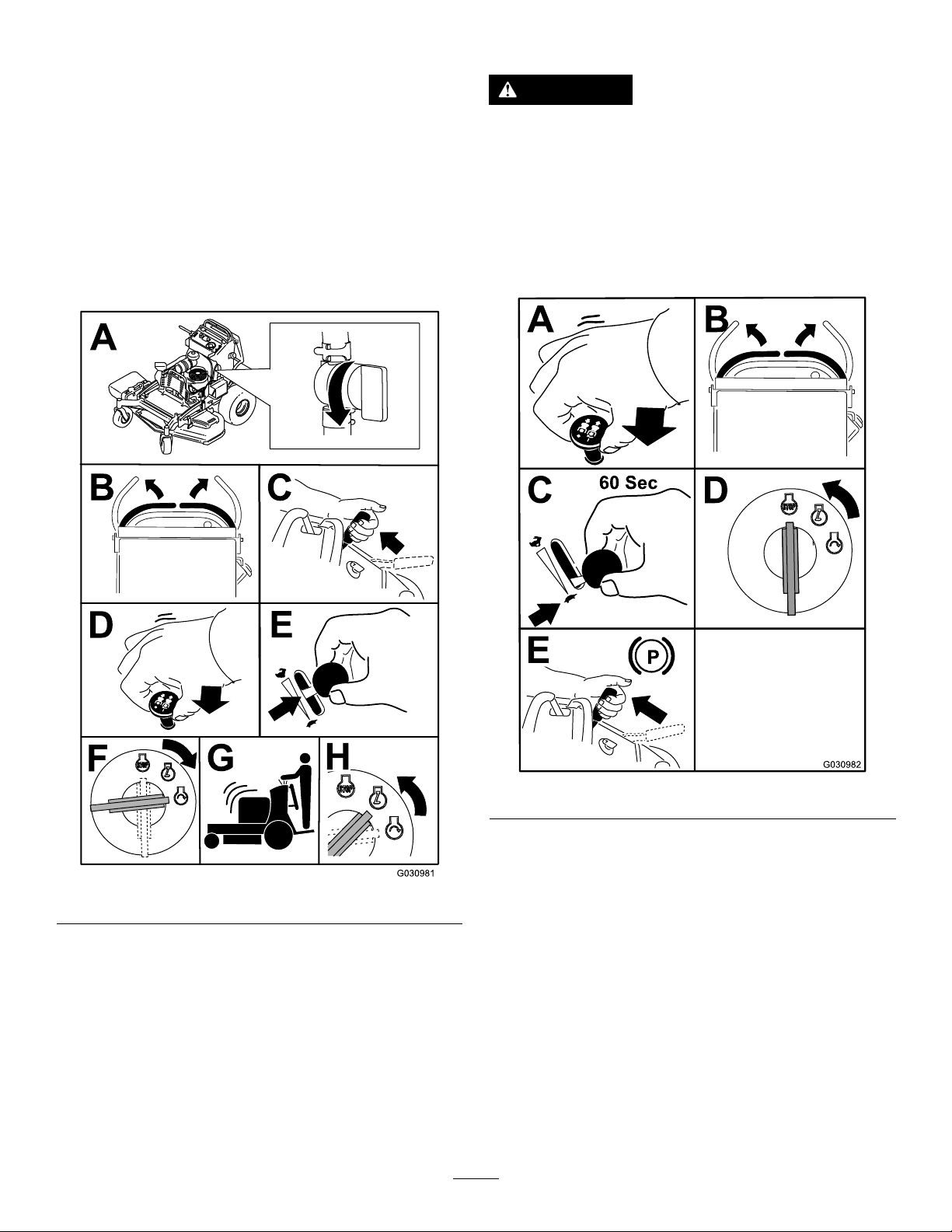
StartingtheEngine
Important:Donotengagethestarterformorethan
5secondsatatime.Iftheenginefailstostart,wait
15secondsbetweenattempts.Failuretofollowthese
instructionscanburnoutthestartermotor.
Note:Youmayneedtorepeatthecycleforstartingthe
enginewhenyoustartitforthersttimeafteryouhavelled
acompletelyemptyfuelsystemwithfuel.
CAUTION
Childrenorbystandersmaybeinjuredifthey
moveorattempttooperatethemachinewhileitis
unattended.
Alwaysremovetheignitionkeyandsettheparking
brakewhenleavingthemachineunattended.
Lettheengineidleatslowthrottle(turtle)for60seconds
beforeturningtheignitionswitchoff.
Figure16
Figure17
Important:Makesurethatthefuel-shutoffvalveis
closedbeforetransportingorstoringthemachine
topreventafuelleak.Beforestoringthemachine,
disconnectthesparkplug(s)topreventthepossibility
ofaccidentalstarting.
18
Page 19

TheSafety-InterlockSystem
Note:Thebladesshouldnotrotateandtheengine
shouldstoprunning.
CAUTION
Ifthesafety-interlockswitchesaredisconnectedor
damaged,themachinecouldoperateunexpectedly,
causingpersonalinjury.
•Donottamperwiththeinterlockswitches.
•Checktheoperationoftheinterlockswitches
dailyandreplaceanydamagedswitchesbefore
operatingthemachine.
UnderstandingtheSafety-Interlock
System
Thesafety-interlocksystemisdesignedtopreventthemower
bladesfromrotatingunlessyoudo1ofthefollowing:
•Moveeithermotion-controllevertothecenter,unlocked
position.
•Pulltheblade-controlswitch(PTO)totheONposition.
Thesafety-interlocksystemisdesignedtostopthemower
bladesifyoumoveorreleasebothmotion-controllevers
intotheNEUTRAL-LOCKposition.
Thehourmeterhassymbolstonotifytheuserwheneach
interlockcomponentisinthecorrectposition.Whenthe
componentisinthecorrectposition,atrianglelightsup
inthecorrespondingsquare(Figure18).
3.Starttheengineandreleasetheparkingbrake.
4.Moveeithermotion-controllevertothecenter,
unlockedposition.
5.Continueholdingthemotion-controlleverinthe
center,unlockedposition,pullupontheblade-control
switch(PTO),andreleasetheswitch.
Note:Theclutchshouldengageandthemower
bladesrotate.
6.Moveorreleasethemotion-controlleversintothe
NEUTRAL-LOCKposition.
Note:Thebladesshouldstoprotatingandtheengine
shouldcontinuetorun.
7.Pushtheblade-controlswitchdownandmoveeither
motion-controllevertothecenter,unlockedposition.
8.Continueholdingthemotion-controlleverinthe
center,unlockedposition,pullupontheblade-control
switch(PTO),andreleasetheswitch.
Note:Theclutchshouldengageandthemower
bladesshouldrotate.
9.Pushtheblade-controlswitch(PTO)downtotheOFF
position.
Note:Thebladesshouldstoprotating.
Figure18
1.Triangleslightupwhentheinterlockcomponentsareinthe
correctposition.
TestingtheSafety-InterlockSystem
ServiceInterval:Beforeeachuseordaily
Testthesafety-interlocksystembeforeyouusethemachine
eachtime.
Note:Ifthesafetysystemdoesnotoperateasdescribed
below,haveanAuthorizedServiceDealerrepairthesafety
systemimmediately.
1.Starttheengine;refertoStartingtheEngine(page18).
2.Movethemotion-controlleverstothecenter,unlocked
position.
10.Withtheenginerunning,pulluptheblade-control
switch(PTO)andreleaseitwithoutholdingeither
motion-controllevertothecenter,unlockedposition.
Note:Thebladesshouldnotrotate.
WARNING
Theoperatorplatformisheavyandmaycause
injurywhenloweringandraisingtheoperator
platform.Carefullylowerorraisetheoperator
platform,assuddenlydroppingitcouldinjureyou.
•Donotputyourhandsorngersinthe
platform-pivotareawhenloweringorraisingthe
operatorplatform.
•Makesurethattheplatformissupportedwhen
youpullthelatchpinout.
•Makesurethatthelatchsecurestheplatform
whenfoldingitup.Pushittightagainstthe
cushionforthelatchpintolockintoplace.
•Keepbystandersawaywhenraisingorlowering
theplatform.
OperatingthePlatform
Youcanusethemachinewiththeplatformintheupordown
position.Itisyourpreferenceonwhichpositiontouse.
19
Page 20

OperatingtheMachinewiththe
PlatformUp
Operatethemachinewiththeplatformupunderthe
followingconditions:
•Mowingneardrop-offs
DrivingForwardorBackward
Thethrottlecontrolregulatestheenginespeedasmeasured
inrpm(revolutionsperminute).Placethethrottlecontrolin
theFASTpositionforbestperformance.Alwaysoperatethe
machineintheFULL-THROTTLEpositionwhenmowing.
•Mowingsmallareaswherethemachineistoolarge
•Areaswithlow ,over-hangingbranchesorobstacles
•Loadingthemachinefortransport
•Drivingupslopes
Toraisetheplatform,pullthebackoftheplatformupsothat
thelatchpinandknoblockitintoplace.Pushittightagainst
thecushionforthelatchpintolockitintoplace.
OperatingtheMachinewiththe
PlatformDown
Operatethemachinewiththeplatformdownunderthe
followingconditions:
•Mowingmostareas
•Drivingacrossslopes
•Drivingdownslopes
Tolowertheplatform,pushtheplatformforwardagainstthe
cushiontoreleasepressureonthelatchpin,thenpullthe
knoboutandlowertheplatform(Figure19).
CAUTION
Themachinecanspinveryrapidly,andyoumay
losecontrolofmachine,causingpersonalinjuryto
youanddamagetomachine.
Slowthemachinedownbeforemakingsharpturns.
DrivingForward
1.Releasetheparkingbrake;refertoReleasingthe
ParkingBrake(page15).
2.Movethemotion-controlleverstothecenter,unlocked
position.
1.Platformup
2.Platformdown
Figure19
3.Pulltheknobouttorelease
theplatform.
Figure20
1.Frontreferencebar
2.Leftcontrollever
3.Rearreferencebar6.Leftcontrolleverinthe
3.Slowlypushthemotion-controlleversforward(Figure
21).
Note:Theenginestopsifyoumoveamotion-control
leverwhiletheparkingbrakeisengaged.
Note:Thefartheryoumovethemotion-controllevers
ineitherdirection,thefasterthemachinemovesinthat
direction.
Note:Tostopthemachine,pullthemotion-control
leversbacktotheNEUTRALposition.
20
4.Rightcontrollever
5.Rightcontrolleverinthe
NEUTRAL-LOCKposition
NEUTRAL-LOCKposition
Page 21

Figure21
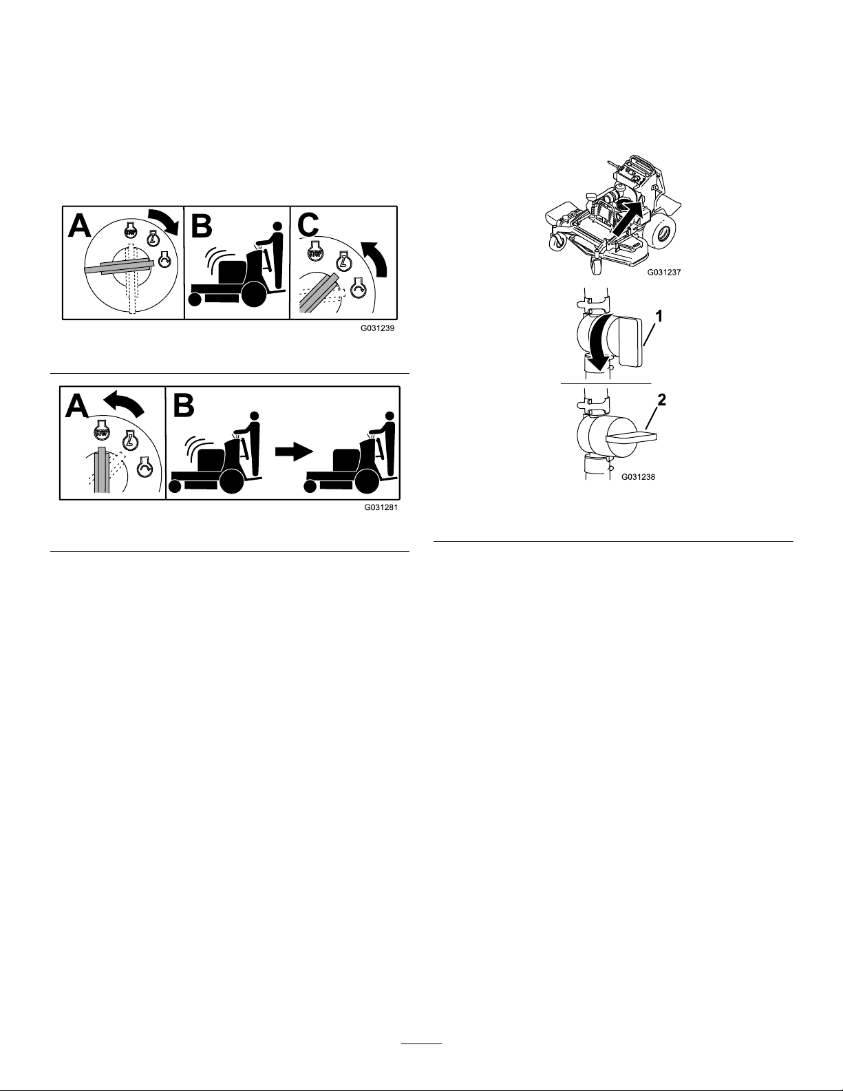
StoppingtheMachine
Tostopthemachine,movethemotion-controllevers
toneutral,movebothmotion-controlleversintothe
NEUTRAL-LOCKposition,disengagethepowertakeoff
(PTO),andturntheignitionkeytotheOFFposition.
Settheparkingbrakewhenyouleavethemachine;referto
SettingtheParkingBrake(page15).
Note:Remembertoremovethekeyfromtheignitionswitch.
CAUTION
Childrenorbystandersmaybeinjurediftheymove
orattempttooperatethemachine.
Alwaysremovetheignitionkeyandsettheparking
brakewhenleavingthemachineunattended.
DrivingBackward
1.Movebothmotion-controlleverstothecenter,
unlockedposition.
2.Slowlypullthemotion-controlleversrearward(Figure
22).
Figure22
21
Page 22

PushingtheMachinebyHand
TransportingtheMachine
Thebypassvalvesallowyoutopushthemachinebyhand
withouttheenginerunning.
Important:Alwayspushthemachinebyhand.Donot
towthemachine,becausehydraulicdamagemayoccur.
Important:Donotstartoroperatethemachinewith
thebypassvalvesopen.Damagetosystemmayoccur.
Useaheavy-dutytrailerortrucktotransportthemachine.
Ensurethatthetrailerortruckhasallthenecessarybrakes,
lighting,andmarkingasrequiredbylaw .Pleasecarefullyread
allthesafetyinstructions.
1.Raisetheplatformofthemachinebeforedrivingonto
thetrailerortruck.
2.Ifusingatrailer,connectittothetowingvehicleand
connectthesafetychains.
3.Ifapplicable,connectthetrailerbrakes.
4.Loadthemachineontothetrailerortruck.
5.Shutofftheengine,removethekey,setthebrake,and
closethefuelvalve.
6.Usethemetaltie-downloopsonthemachineto
securelyfastenthemachinetothetrailerortruckwith
straps,chains,cable,orropes(Figure24).
Figure23
Figure24
1.Tractionunittie-downloop
LoadingtheMachine
Useextremecautionwhenloadingorunloadingmachines
ontoatraileroratruck.Useafull-widthrampthatiswider
thanthemachineforthisprocedure.Backthemachineupthe
rampandwalkitforwarddowntheramp(Figure25).
Figure25
1.Backthemachineupthe
ramp.
2.Walkthemachinedown
theramp.
22
Page 23

Important:Donotusenarrowindividualrampsfor
g027996
5
1
2
6
eachsideofthemachine.
Ensurethattherampislongenoughsothattheanglewith
thegrounddoesnotexceed15degrees(Figure26).Onat
ground,thisrequiresaramptobeatleast4timesaslongas
theheightofthetrailerortruckbedtotheground.Asteeper
anglemaycausemowercomponentstogetcaughtasthe
machinemovesfromtheramptothetrailerortruck.Steeper
anglesmayalsocausethemachinetotiporlosecontrol.If
youareloadingthemachineonornearaslope,positionthe
trailerortrucksothatitisonthedownsideoftheslopeand
therampextendsuptheslope.Thiswillminimizetheramp
angle.
WARNING
Loadingamachineontoatrailerortruckincreases
thepossibilityoftip-overandcouldcauseserious
injuryordeath.
•Useextremecautionwhenoperatingamachine
onaramp.
•Useonlyafull-widthramp;donotuseindividual
rampsforeachsideofthemachine.
•Donotexceeda15-degreeanglebetweenthe
rampandthegroundorbetweentherampand
thetrailerortruck.
•Ensurethatthelengthoftherampisatleast4
timesaslongastheheightofthetrailerortruck
bedtotheground.Thiswillensurethatthe
rampangledoesnotexceed15degreesonat
ground.
•Backthemachineuptherampandwalkit
forwarddowntheramp.
•Avoidsuddenaccelerationordecelerationwhile
drivingthemachineonaramp,asthiscould
causealossofcontroloratip-oversituation.
1.Full-widthrampinstowed
position
2.Sideviewoffull-width
rampinloadingposition
3.Notgreaterthan
15degrees
Figure26
4.Therampisatleast4
timesaslongastheheight
ofthetrailerortruckbed
totheground
5.H=heightofthetraileror
truckbedtotheground
6.Trailer
23
Page 24

SideDischargingorMulching
AdjustingtheHeight-of-Cut
theGrass
Thismowerhasahingedgrassdeectorthatdisperses
clippingstothesideanddowntowardtheturf.
DANGER
Withoutthegrassdeector,dischargecover,or
completegrasscatcherassemblymountedin
place,youandothersareexposedtobladecontact
andthrowndebris.Contactwithrotatingmower
blade(s)andthrowndebriscauseinjuryordeath.
•Donotremovethegrassdeectorfrom
themower,becausethegrassdeector
routesmaterialdowntowardtheturf.Ifthe
grassdeectoriseverdamaged,replaceit
immediately.
•Neverputyourhandsorfeetunderthemower.
•Nevertrytoclearthedischargeareaormower
bladesunlessyoureleasethebailandthepower
takeoff(PTO)isoff.Rotatetheignitionkey
totheOFFposition.Alsoremovethekeyand
disconnectthewire(s)offthesparkplug(s).
Theheight-of-cutcanbeadjustedfrom38to127mm(1-1/2
to5inches)in6mm(1/4inch)increments.
Note:Usingaheight-of-cutunder51mm(2inches)increases
thewearonthemower-deckbelt.Useaheight-of-cutthatis
greaterthan51mm(2inches)wheneverpossible.
Figure27
24
Page 25

AdjustingtheFlowBafe
g012676
1 2
G012677
PositioningtheFlowBafe
Youcanadjustthemower-dischargeowfordifferenttypes
ofmowingconditions.Positionthecamlockandbafeto
providethebestqualityofcut.
1.DisengagethePTO,movethemotion-controlleversto
theNEUTRAL-LOCKposition,andsettheparkingbrake.
2.Shutofftheengine,removethekey ,andwaitforall
movingpartstostopbeforeleavingtheoperating
position.
3.Toadjustthebafe,loosenthenut(Figure28).
4.Adjustthebafeandnutintheslottothedesired
dischargeowandtightenthenut.
Thefollowingguresareonlyforrecommendeduse.
Adjustmentsvarybygrasstype,moisturecontent,andthe
heightofthegrass.
Note:Iftheenginepowerdrawsdown,andthemower
groundspeedisthesame,openupthebafe.
PositionA
Thisisthefull,rearposition(seeFigure29).Usethisposition
forthefollowing:
•Inshort,lightgrassmowingconditions
•Indryconditions
•Smallergrassclippings
•Propelsgrassclippingsfartherawayfromthemower
Figure28
1.Slot
2.Nut
Figure29
25
Page 26

PositionB
G012678
G012679
Usethispositionwhenbagging(Figure30).
UsingtheMid-SizeWeight
•Installweightstoimprovebalance.Youcanaddor
removeweightstocreateoptimizedperformanceunder
differentmowingconditionsandforyourpreference.
•Addorremoveweights1atatimeuntilyouachievethe
desiredhandlingandbalance.
Note:ContactanAuthorizedServiceDealertoordera
WeightKit.
WARNING
Excessiveweightchangescanaffectthehandling
andoperationofthemachine.Thiscouldcause
seriousinjurytoyouorbystanders.
•Makeweightchangesinsmallincrementsonly.
Figure30
PositionC
Thisisthefull,openposition(Figure31).Useforthis
positionforthefollowing:
•Intall,densegrassmowingconditions
•Inwetconditions
•Lowerstheengine-powerconsumption
•Allowsincreasedgroundspeedinheavyconditions
•Evaluatethatyoucanoperatethemowerafter
eachweightchangesafely.
Figure31
26
Page 27

Maintenance
Note:Determinetheleftandrightsidesofthemachinefromthenormaloperatingposition.
RecommendedMaintenanceSchedule(s)
MaintenanceService
Interval
Aftertherst8hours
Aftertherst50hours
Aftertherst100hours
Beforeeachuseordaily
Every50hours
Every100hours
Every200hours
Every250hours
MaintenanceProcedure
•Changetheengineoil.
•Checkthehydraulic-uidlevel.
•Changethehydraulicltersandhydraulicuid.
•Checkthewheel-lugnuts.
•Checkthewheel-hubnuts.
•Checkthesafety-interlocksystem.
•Checktheengine-oillevel.
•Cleantheair-intakescreen.
•Checkthebrakes.
•Inspecttheblades.
•Cleanthemowerdeck.
•Checkthesparkarrester(ifequipped).
•Checkthetirepressure.
•Changetheengineoil(moreoftenindirtyordustyconditions).
•Check,cleanandgapthesparkplug.
•Checkthebattery .
•Checkandcleantheenginecoolingnsandshrouds.
•Checkthemower-deckbelt.
•Changetheengine-oillter.
•Replacetheprimaryairlter.
•Checkthesecondaryairlter.
Every300hours
Every500hours
Every800hours
Every1,000hours
Beforestorage
Yearly
•Checkandadjustthevalveclearance.SeeanAuthorizedServiceDealer.
•Replacethesecondaryairlter.
•Adjustthecaster-pivotbearing.
•Checkthewheel-hubnuts.
•Checkthehydraulic-uidlevel.
•Changethehydraulicltersandhydraulicuid.
•Replacethefuellter.
•Replacethetransmissionbelt.
•Paintchippedsurfaces.
•Performallmaintenanceprocedureslistedabovebeforestorage.
•Greasethetorsionidler.
•Greasethefrontcasterpivots(moreoftenindirtyordustyconditions).
•Greasethecaster-wheelhubs.
Important:Refertoyourengineowner’smanualforadditionalmaintenanceprocedures.
CAUTION
Ifyouleavethekeyintheignitionswitch,someonecouldaccidentlystarttheengineandseriouslyinjure
youorotherbystanders.
Removethekeyfromtheignitionanddisconnectthespark-plugwiresfromthesparkplugsbeforeyoudo
anymaintenance.Setthewiresasidesothattheydonotaccidentallycontactthesparkplugs.
27
Page 28

Premaintenance
Lubrication
Procedures
ReleasingtheCushionfor RearAccess
Youcanreleasethecushionforrearaccesstothemachinefor
maintenanceoradjustment.
1.Lowertheplatform.
2.Loosenthetwistknobsoneachsideofthemachine
(Figure32).
Figure32
1.Twistknob
2.Cushion
1.DisengagethePTOandsettheparkingbrake.
2.Shutofftheengine,removethekey ,andwaitforall
movingpartstostopbeforeleavingtheoperating
position.
3.Cleanthegreasettingswitharag.
Note:Makesuretoscrapeanypaintoffthefrontof
thetting(s).
4.Connectagreaseguntothetting.
5.Pumpgreaseintothettingsuntilgreasebeginsto
oozeoutofthebearings.
6.Wipeupanyexcessgrease.
GreasingtheTorsionIdler
ServiceInterval:Yearly
Greasethetorsionidleronthemowerdeckusing
high-temperaturegreaseatthegreasettingshowninFigure
33.
Important:Onlyusehigh-temperaturegrease.
3.Removethecushionandlowerittotheplatform.
4.Performanymaintenanceoradjustmentonthe
machine.
5.Raisethecushion,andslideitontothepinsonboth
sidesofthemachine.
6.Tightenthetwistknobs.
Figure33
1.Greasetting
28
Page 29

GreasingtheFrontCaster Pivots
ServiceInterval:Yearly
1.Removethedustcapandadjustthecasterpivots;refer
toAdjustingtheCaster-PivotBearing(page40).
Note:Keepthedustcapoffuntilyouhavenished
greasingthecasterpivots.
2.Removethehexplug.
3.Threadagreasettingintothehole.
4.Pumpgreaseintothettinguntilitoozesoutaround
thetopbearing.
5.Removethegreasettingfromthehole.
6.Installthehexpluganddustcap.
GreasingtheCaster-Wheel
8.Ifbothspacernutsintheaxleassemblyhavebeen
removed(orbrokenloose),applyathread-locking
adhesiveto1spacernut,threadingitontotheaxlewith
thewrenchatsfacingoutward.
Note:Donotthreadspacernutallofthewayonto
theendoftheaxle.Leaveapproximately3mm(1/8
inch)fromtheoutersurfaceofthespacernuttothe
endoftheaxleinsidethenut.
9.Inserttheassemblednutandaxleintothewheelonthe
sideofthewheelwiththenewsealandbearing.
10.Withtheopenendofthewheelfacingup,llthearea
insidethewheelaroundtheaxlefullofgeneral-purpose
grease.
11.Insertthesecondbearingandthenewsealintothe
wheel.
12.Applyathread-lockingadhesivetothesecondspacer
nut,threadingitontotheaxlewiththewrenchats
facingoutward.
Hubs
ServiceInterval:Yearly
1.Shutofftheengine,waitforallmovingpartstostop,
engagetheparkingbrake,andremovethekey .
2.Removethecasterwheelfromthecasterforks.
3.Removethesealguardsfromthewheelhub(Figure34).
Figure34
1.Sealguard2.Spacernutwithwrench
ats
13.Torquethenutto8to9N∙m(71to80in-lb),loosenit,
thentorqueitto2to3N∙m(20to25in-lb).
Note:Makesurethataxledoesnotextendbeyond
eithernut.
14.Installthesealguardsoverthewheelhubandinsert
wheelintocasterfork.
15.Installthecasterboltandtightenthenutfully.
Important:Topreventsealandbearingdamage,check
thebearingadjustmentoftenbyspinningthecaster
tire.Thetireshouldnotspinfreely(morethan1or2
revolutions)orhaveanysideplay.Ifthewheelspins
freely,adjustthetorqueonthespacernutuntilthere
isaslightamountofdrag,andapplythread-locking
adhesive.
4.Remove1spacernutfromtheaxleassemblyinthe
casterwheel.
Note:Thread-lockingadhesivehasbeenappliedto
lockthespacernutstotheaxle.Removetheaxle(with
theotherspacernutstillassembledtoit)fromthe
wheelassembly.
5.Pryouttheseals,inspectbearingsforwearordamage,
andreplacethemifnecessary.
6.Packthebearingswithageneral-purposegrease.
7.Insert1bearingand1newsealintothewheel.
Note:Youmustreplacetheseals.
29
Page 30

EngineMaintenance
g026970
ServicingtheAirCleaner
ServiceInterval:Every300hours
Every250hours—Replacetheprimaryairlter.
Every250hours—Checkthesecondaryairlter.
Every500hours—Replacethesecondaryairlter.
Note:Servicetheaircleanermorefrequentlyifoperating
conditionsareextremelydustyorsandy.
Figure35
RemovingtheFilters
1.DisengagethePTO,movethemotion-controlleversto
theNEUTRAL-LOCKposition,andsettheparkingbrake.
2.Shutofftheengine,removethekey ,andwaitforall
movingpartstostopbeforeleavingtheoperating
position.
3.Pushdowntoreleasetheretainingclampsontheair
cleanerandpulltheair-cleanercoverofftheair-cleaner
body(Figure35).
4.Cleantheinsideoftheair-cleanercoverwith
compressedair.
5.Gentlyslidetheprimarylteroutoftheair-cleaner
body(Figure35).
Note:Avoidknockingthelterintothesideofthe
body.
6.Removethesecondarylteronlyifyouintendto
replaceit.
Important:Neverattempttocleanthesecondary
lter.Ifthesecondarylterisdirty,thenthe
primarylterisdamagedandyoushouldreplace
bothlters.
7.Inspecttheprimarylterfordamagebylookinginto
thelterwhileshiningabrightlightontheoutsideof
thelter.
1.Air-cleanerclamps
2.Air-cleanercover
3.Primaryairlter
4.Secondaryairlter
ServicingthePrimaryFilter
1.Inspecttheelementfortears,anoilylm,ordamageto
therubberseal.
2.Replacethepaperelementifitisdamaged.
Note:Donotcleanthepaperelement.
ServicingtheSecondaryFilter
Donotcleanthesecondarylter,replaceit.
Important:Donotattempttocleanthesecondarylter.
Ifthesecondarylterisdirty,thentheprimarylteris
damagedandyoushouldreplacebothlters.
InstallingtheFilters
Important:T opreventenginedamage,alwaysoperate
theenginewithbothairltersandthecoverinstalled.
1.Ifinstallingnewlters,checkeachlterforshipping
damage.
Note:Donotuseadamagedlter.
Note:Holesinthelterappearasbrightspots.
Note:Discardthelterifitisdamaged.
2.Ifthesecondarylterisbeingreplaced,carefullyslide
itintothelterbody(Figure35).
3.Carefullyslidetheprimarylteroverthesecondary
lter(Figure35).
4.Ensurethatitisfullyseatedbypushingontheouter
rimofthelterwhileinstallingit.
Important:Donotpressonthesoftinsidearea
ofthelter.
5.Installtheair-cleanercoverwiththebreathercapdown,
androtatesothattheretainingclampslockthecover
inplace(Figure35).
30
Page 31

ServicingtheEngineOil
B
A
C
D
E
G027659
F
G
H
I J
ServiceInterval:Beforeeachuseordaily—Checkthe
engine-oillevel.
Aftertherst8hours
Every100hours—Changetheengineoil(moreoften
indirtyordustyconditions).
Every200hours—Changetheengine-oillter.
Note:Therearedifferentoilcapacitiesforthedifferent
modelslistedinthismanual.Ensurethatyouusethecorrect
amountofoil.
Important:Remembertoadd80%oftheoil,andthen
graduallyllittotheFullmarkonthedipstick.
OilType::Detergentoil(APIserviceSF,SG,SH,SJorSL)
EngineOilCapacity:2.1L(71oz)withthelterremoved;
1.8L(61oz)withoutthelterremoved
Viscosity:Refertothetablebelow .
3.Checktheengine-oillevelasshowninFigure37.
Figure36
CheckingtheEngine-OilLevel
Note:Checktheoilwhentheengineiscold.
WARNING
Contactwithhotsurfacesmaycausepersonal
injury.
Keephands,feet,face,clothingandotherbody
partsawaythemuferandotherhotsurfaces.
Important:Donotruntheenginewiththeoillevel
abovetheFullmarkorbelowthelowmark.Otherwise,
doingsomaydamagetheengine.
1.DisengagethePTO,movethemotion-controlleversto
theNEUTRAL-LOCKposition,andsettheparkingbrake.
2.Shutofftheengine,removethekey ,andwaitforall
movingpartstostopbeforeleavingtheoperating
position(Figure37).
Figure37
31
Page 32

ChangingtheEngineOil
B
A
C
D
E
F
g027660
Note:Disposeoftheusedoilatarecyclingcenter.
1.Parkthemachinesothatthedrainsideisslightlylower
thantheoppositesidetoensurethattheoildrains
completely.
2.DisengagethePTO,movethemotion-controlleversto
theNEUTRAL-LOCKposition,andsettheparkingbrake.
3.Shutofftheengine,removethekey ,andwaitforall
movingpartstostopbeforeleavingtheoperating
position.
4.ChangetheengineoilasshowninFigure38.
Figure39
6.Starttheengineanddrivetoaatarea.
7.Checktheengineoillevel.
Figure38
5.Slowlypourapproximately80%ofthespeciedoil
intothellertube,andslowlyaddtheadditionaloilto
bringittotheFullmark(Figure39).
32
Page 33

ChangingtheEngine-OilFilter
B
A
C D
E
F
3/4
g027477
B
A
g027478
Note:Changetheengine-oilltermorefrequentlywhen
operatingconditionsareextremelydustyorsandy.
1.Draintheoilfromtheengine;refertoChangingthe
EngineOil(page32).
2.Placearagundertheoilltertosoakupanyspilledoil.
Important:Spilledoilmaydrainundertheengine
andontotheclutch.Oilspilledontheclutchmay
damagetheclutch,causethebladestostopslowly
whentheclutchisintheOFFposition,andcause
theclutchtoslipwhentheclutchisswitchedto
theONposition.Wipeupanyspilledoil.
3.Changetheengine-oillter(Figure40).
ServicingtheSparkPlug
ServiceInterval:Every100hours
Makesurethattheairgapbetweenthecenterandside
electrodesiscorrectbeforeinstallingthesparkplug.
Useasparkplugwrenchforremovingandinstallingthespark
plug(s)andagappingtool/feelergaugetocheckandadjust
theairgap.Installanewsparkplug(s)ifnecessary.
TypeforallEngines:NGK
AirGap:0.75mm(0.03inch)
RemovingtheSparkPlugs
1.DisengagethePTO,movethemotion-controlleversto
theNEUTRAL-LOCKposition,andsettheparkingbrake.
2.Shutofftheengine,removethekey ,andwaitforall
movingpartstostopbeforeleavingtheoperating
position.
3.RemovethesparkplugsasshowninFigure41.
®
BPR4ESorequivalent
4.Fillthecrankcasewiththepropertypeofnewoil;refer
Note:Ensurethattheoil-ltergaskettouchesthe
engine,thenrotatethelteranextra3/4turn.
toChangingtheEngineOil(page32).
Figure40
Figure41
33
Page 34

CheckingtheSparkPlug
B
A
g027479
B
A
16 ft-lb
22 N-m
g027661
C
D
CheckingtheSparkArrester
Important:Donotcleanthesparkplug(s).Always
replacethesparkplug(s)whenithasablackcoating,
wornelectrodes,anoilylm,orcracks.
Ifyouseelightbrownorgrayontheinsulator,theengineis
operatingproperly .Ablackcoatingontheinsulatorusually
meanstheaircleanerisdirty.
Setthegapto0.75mm(0.03inch).
Figure42
InstallingtheSparkPlug
IfEquipped
ServiceInterval:Every50hours
WARNING
Hotexhaust-systemcomponentsmayignite
gasolinevaporsevenafteryoushutofftheengine.
Hotparticlesexhaustedduringengineoperation
mayigniteammablematerials,resultingin
personalinjuryorpropertydamage.
Donotrefuelorruntheengineunlessthespark
arresterisinstalled.
1.Shutofftheengine,waitforallmovingpartstostop,
engagetheparkingbrake,andremovethekey .
2.Waitforthemufertocool.
3.Ifyouseeanybreaksinthescreenorwelds,replace
thearrester.
4.Ifthescreenisplugged,removethearrester,shake
looseparticlesoutofthearrester,andcleanthe
screenwithawirebrush(soakthescreeninsolvent
ifnecessary).
5.Installthearresterontheexhaustoutlet.
Figure43
34
Page 35

FuelSystem
Maintenance
DrainingtheFuelTank
Youcandrainthefueltankbyremovingitandpouringthe
fueloutofthellneck;refertoRemovingtheFuelTank
(page35).Youcanalsodrainthefueltankbyusingasiphon
inthefollowingprocedure.
DANGER
Incertainconditions,gasolineisextremely
ammableandhighlyexplosive.Areorexplosion
fromgasolinecanburnyouandothersandcan
damageproperty.
•Draingasolinefromthefueltankwhenthe
engineiscold.Dothisoutdoorsinanopenarea.
Wipeupanygasolinethatspills.
•Neversmokewhendraininggasoline,andstay
awayfromanopename,orwhereasparkmay
ignitethegasolinefumes.
Figure44
1.Fuelcap
RemovingtheFuelTank
1.Lowertheplatform.
2.Releasethecushion;refertoReleasingtheCushionfor
RearAccess(page28).
1.DisengagethePTO,movethemotion-controlleversto
theNEUTRAL-LOCKposition,andsettheparkingbrake.
2.Shutofftheengine,removethekey ,andwaitforall
movingpartstostopbeforeleavingtheoperating
position.
3.Cleanaroundthefuelcaptopreventdebrisfrom
gettingintothefueltank(Figure44).
4.Removethefuelcap.
5.Insertasyphonpumpintothefueltank.
6.Usingthesyphonpump,drainthefuelintoacleangas
can(Figure44).
7.Wipeupanyspilledfuel.
3.Removethecrossbracket.
Figure45
4.Removethefueltankandsetitontheoperator
platform.
Note:Ifyouwanttomovethefueltankfurtherfrom
themachine,removethefuelandventlinesfromthe
topofthetank.
35
Page 36

ServicingtheFuelFilter
B
A
C
D
g027518
ElectricalSystem
ReplacingtheFuelFilter
ServiceInterval:Every800hours/Y early(whichevercomes
rst)
Donotinstalladirtylterifitisremovedfromthefuelline.
Note:Wipeupanyspilledfuel.
1.DisengagethePTOandsettheparkingbrake.
2.Shutofftheengine,removethekey ,andwaitforall
movingpartstostopbeforeleavingtheoperating
position.
3.Closethefuel-shutoffvalve;refertoUsingthe
Fuel-ShutoffValve(page17).
4.ReplacethefuellterasshowninFigure46.
Maintenance
ServicingtheBattery
ServiceInterval:Every100hours
Alwayskeepthebatterycleanandfullycharged.Useapaper
toweltocleanthebatterycase.Ifthebatteryterminalsare
corroded,cleanthemwithasolutionof4partswaterand
1partbakingsoda.Applyalightcoatingofgreasetothe
batteryterminalstopreventcorrosion.
Voltage:12V
WARNING
CALIFORNIA
Proposition65W arning
Batteryposts,terminals,andrelated
accessoriescontainleadandleadcompounds,
chemicalsknowntotheStateofCalifornia
tocausecancerandreproductiveharm.
Washhandsafterhandling.
Figure46
DANGER
Donotdrinkelectrolyte,andavoidcontactwith
skin,eyesorclothing.Wearsafetyglassestoshield
youreyesandrubberglovestoprotectyourhands.
Batteryelectrolytecontainssulfuricacid,adeadly
poisonthatcausessevereburns.
RemovingtheBattery
WARNING
Batteryterminalsormetaltoolscouldshortagainst
metalmachinecomponents,causingsparks.Sparks
cancausethebatterygassestoexplode,resulting
inpersonalinjury.
•Whenremovingorinstallingthebattery,donot
allowthebatteryterminalstotouchanymetal
partsofthemachine.
•Donotallowmetaltoolstoshortbetween
thebatteryterminalsandmetalpartsofthe
machine.
36
Page 37

WARNING
Incorrectbattery-cableroutingcoulddamagethe
machineandcables,causingsparks.Sparkscan
causethebatterygassestoexplode,resultingin
personalinjury.
•Alwaysdisconnectthenegative(black)battery
cablebeforedisconnectingthepositive(red)
cable.
•Alwaysconnectthepositive(red)batterycable
beforeconnectingthenegative(black)cable.
1.DisengagethePTOandsettheparkingbrake.
2.Shutofftheengine,removethekey ,andwaitforall
movingpartstostopbeforeleavingtheoperating
position.
3.RemovethebatteryasshowninFigure47.
InstallingtheBattery
InstallthebatteryasshowninFigure48.
Figure47
Figure48
37
Page 38

ChargingtheBattery
ServicingtheFuses
WARNING
Chargingthebatteryproducesgassesthatcan
explode.
Neversmokenearthebatteryandkeepsparksand
amesawayfrombattery.
Important:Alwayskeepthebatteryfullycharged
(1.265specicgravity)topreventbatterydamagewhen
thetemperatureisbelow0°C(32°F).
1.Removethebatteryfromthechassis;refertoRemoving
theBattery(page36).
2.Checktheelectrolytelevel.
3.Ensurethatthellercapsareinstalledonthebattery.
4.Chargethebatteryfor1hourat25to30Aor6hours
at4to6A.
5.Whenthebatteryisfullycharged,unplugthecharger
fromtheelectricaloutlet,anddisconnectthecharger
leadsfromthebatteryposts(Figure49).
6.Installthebatteryontothemachineandconnectthe
batterycables;refertoInstallingtheBattery(page37).
Note:Donotrunthemachinewiththebattery
disconnected;electricaldamagemayoccur.
Theelectricalsystemisprotectedbyfusesandrequiresno
maintenance.Ifafuseblows,checkthecomponentorcircuit
foramalfunctionorshort.
1.Releasethecushionfromtherearofthemachine.
2.Pulloutthefusetoremoveorreplaceit(Figure50).
3.Installthecushiontotherearofthemachine.
Note:Ensurethatthecorrect-sizefuseisinstalled
Figure50.
Figure50
1.Ignitionfuse—15A3.Powertakeoff(PTO)
2.Accessory-portfuse—15
A
fuse—10A
4.Infocenterfuse—7.5A
1.Positivebatterypost
2.Negativebatterypost
Figure49
3.Red(+)chargerlead
4.Black(-)chargerlead
38
Page 39

DriveSystem
6.Checkthatthemachinedoesnotcreepfromthe
neutralpositionwiththeparkbrakesdisengaged.
Maintenance
AdjustingtheTracking
Note:Determinetheleftandrightsidesofthemachine
fromthenormaloperatingposition.
1.Pushbothcontrolleversforwardthesamedistance.
2.Checkifthemachinepullsto1side.
Note:Ifitdoes,stopthemachineandsettheparking
brake.
3.Releasethecushionfromtherearofthemachine;refer
toReleasingtheCushionforRearAccess(page28).
Note:Foreasieraccess,youcanalsoremovethefuel
tank;refertoRemovingtheFuelTank(page35).
4.Rotatetheleftcontrolrodinquarter-turnincrements
untilthemachinetracksstraight(Figure51).
Note:Ifthemachinepullstotheright,shortenthe
controlrodbyrotatingittotheright.Ifthemachine
pullstotheleft,lengthentherodbyrotatingittothe
left.
7.Installthefueltank,ifyouremovedit.
8.Installthecushion.
CheckingtheTirePressure
ServiceInterval:Every50hours/Monthly(whichever
comesrst)
Maintaintheairpressureinthereartiresat83to97kPa(12
to14psi).
Important:Uneventirepressurecancauseanuneven
cut.
Note:Thefronttiresaresemi-pneumatictiresanddonot
requireair-pressuremaintenance.
Note:Onlyadjusttheleftcontrolrodtomatchthe
leftwheelspeedtotherightwheelspeed.Donot
adjusttherightwheelspeed,asthispositionstheright
motion-controlleveroutofthecenterforthecontrol
panelneutral-lockslot.
Important:Donotrotatethecontrolrodtoofar,
asthismaycausethemachinetocreepinneutral.
Figure51
1.Rotatelefttolengthenthe
rod.
2.Leftcontrolrod
3.Rotaterighttoshortenthe
rod.
Figure52
5.Checkforpropertracking,andadjusttherodas
necessary.
Note:Ifyouareunabletoachievepropertrackingby
adjustingtheleftcontrolrod,contactyourAuthorized
ServiceDealer.
39
Page 40

AdjustingtheCaster-Pivot
ServicingtheCasterWheels
Bearing
ServiceInterval:Every500hours/Y early(whichevercomes
rst)
1.Disengagetheblade-controlswitch(PTO),movethe
motion-controlleverstotheNEUTRAL-LOCKposition,
andsettheparkingbrake.
2.Shutofftheengine,removethekey ,andwaitforall
movingpartstostopbeforeleavingtheoperating
position.
3.Removethedustcapfromthecasterandtightenthe
locknut(Figure53).
4.Tightenthelocknutuntilthespringwashersareat,
andthenbackoffa1/4turntoproperlysetthepreload
onthebearings(Figure53).
Important:Makesurethatthespringwashersare
installedcorrectlyasshowninFigure53.
5.Installthedustcap(Figure53).
andBearings
Thecasterwheelsrotateonarollerbearingsupportedbya
spannerbushing.Ifthebearingiskeptwelllubricated,wear
willbeminimal.Failuretokeepthebearingwelllubricated
causesrapidwear.Awobblycasterwheelusuallyindicatesa
wornbearing.
1.Removethelocknutandwheelboltholdingthecaster
wheeltothecasterfork(Figure54).
1.Springwashers
2.Locknut
Figure53
3.Dustcap
Figure54
1.Locknut
2.Wheelbolt5.Rollerbearing
3.Bushing
2.Remove1bushing,thenpullthespannerbushingand
rollerbearingoutofthewheelhub(Figure54).
3.Removetheotherbushingfromthewheelhuband
cleananygreaseanddirtfromthewheelhub(Figure
54).
4.Inspecttherollerbearing,bushings,spannerbushing
andtheinsideofthewheelhubforwear.
Note:Replaceanydamagedorwornparts(Figure54).
5.Place1bushingintothewheelhub(Figure54).
6.Greasetherollerbearingandspannerbushing,and
slidethemintothewheelhub(Figure54).
7.Placethesecondbushingintothewheelhub(Figure
54).
8.Installthecasterwheelintothecasterforkandsecure
itwiththewheelboltandlocknut(Figure54).
4.Spannerbushing
9.Tightenthelocknutuntilthespannerbushingbottoms
againsttheinsideofthecasterforks(Figure54).
10.Greasethettingonthecasterwheel.
40
Page 41

UsingtheClutchShim
Somelatermodelyearunitshavebeenbuiltwithclutchesthat
containabrakeshim.Whentheclutchbrakehasworntothe
pointwheretheclutchnolongerengagesconsistently ,you
canremovetheshimtoextendtheclutchlife.
Figure55
1.Armature5.Brakespacer
2.Fieldshell6.Regaptheshim.
3.Rotor7.Brakepole
4.Brake-mountingbolt
A.Loosenbothbrakemountingbolts1/2to1full
turnasshowninFigure57.
Note:Donotremovethebrakepolefromthe
eldshell/armature.Thebrakepolehasworn
tomatchthearmatureandneedstocontinueto
matchafteryouremovetheshimtoensurethe
properbraketorque.
Figure57
1.Brake-mountingbolt
B.Usingneedle-nosepliers,orbyhand,removethe
shim.
RemovingtheClutchShim
1.Shutofftheengine,waitforallmovingpartstostop,
andremovethekey.
2.Engagetheparkingbrakeandwaitformachinetocool
completely.
3.Usinganaircompressor,blowoutanydebrisunderthe
brakepoleandaroundthebrakespacers.
Figure56
4.Checktheconditionofthewire-harnessleads,
connectors,andterminals.Cleanorrepairthemas
necessary.
5.Verifythat12Vispresentattheclutchconnector
whentheyouengagetheblade-controlswitch(PTO).
6.Measurethegapbetweentherotorandarmature.If
thegapisgreaterthan1mm(0.04inch),proceedwith
thefollowingsteps:
Note:Donotdiscardtheshimuntilyouconrm
thattheclutchfunctionsproperly.
Figure58
1.Shim
C.Usingapneumaticline,blowoutanydebrisunder
thebrakepoleandaroundthebrakespacers.
D.Torqueeachbolt(M6x1)to12.3to13.7N∙m
(9.5to10.5ft-lb).
E.Usinga0.010inchthick-feelergauge,verifythat
agapispresentbetweentherotorandarmature
faceonbothsidesofthebrakepoleasshownin
Figure59andFigure60.
Note:Duetothewaytherotorandarmature
faceswear(peaksandvalleys),itissometimes
difculttomeasurethetruegap.
41
Page 42

CheckingtheWheel-LugNuts
ServiceInterval:Aftertherst100hours—Checkthe
wheel-lugnuts.
Checkandtorquethewheellugnutsto115to142N∙m(85
to105ft-lb).
1.Feelergauge
1.Feelergauge
Figure59
Figure60
•Ifthegapislessthan0.010inch,theninstall
theshimandrefertoTroubleshooting(page
56).
•Ifthegapissufcient,proceedtothesafety
checkinstepF.
CheckingtheWheel-HubNuts
ServiceInterval:Aftertherst100hours—Checkthe
wheel-hubnuts.
Every500hours—Checkthewheel-hubnuts.
Checkandtorquethewheelhubnutsto286to352N∙m(211
to260ft-lb).
F.Performthefollowingsafetycheck:
i.Sitontheseatandstarttheengine.
ii.Makesurethatthebladesdonotengage
whentheblade-controlswitch(PTO)
isintheOFFpositionandtheclutchis
disengaged.
Note:Iftheclutchdoesnot
disengage,installtheshim,andreferto
Troubleshooting(page56).
iii.Engageanddisengagetheblade-control
switch(PTO)10consecutivetimesto
ensurethattheclutchisfunctioning
properly.
Note:Iftheclutchdoesnotengage
properly,refertoTroubleshooting(page
56).
42
Page 43

CoolingSystem
Maintenance
BrakeMaintenance
ServicingtheBrake
CleaningtheAir-IntakeScreen
ServiceInterval:Beforeeachuseordaily
Beforeeachuse,removeanybuildupofgrass,dirt,or
otherdebrisfromthecylinderandcylinder-headcooling
ns,air-intakescreenontheywheelend,andthe
carburetor-governorleversandlinkage.Thishelpsensurethat
adequatecoolingandcorrectenginespeed,andreducesthe
possibilityofoverheatingormechanicaldamagetotheengine.
CleaningtheCoolingSystem
ServiceInterval:Every100hours—Checkandcleanthe
enginecoolingnsandshrouds.
1.DisengagethePTOandsettheparkingbrake.
2.Shutofftheengine,removethekey ,andwaitforall
movingpartstostopbeforeleavingtheoperating
position.
3.Removetheair-intakescreenandfanhousing(Figure
61).
4.Cleanthedebrisandgrassfromtheengineparts.
5.Installtheair-intakescreenandfanhousing(Figure61).
Beforeeachuse,checkthebrakesonalevelsurfaceandslope.
Alwayssettheparkingbrakewhenyoustopthemachineor
leaveitunattended.
Important:Iftheparkingbrakedoesnotholdsecurely,
adjustit.
CheckingtheParkingBrake
ServiceInterval:Beforeeachuseordaily
1.Parkthemachineonalevelsurfaceanddisengagethe
PTO.
2.Shutofftheengine,removethekey ,andwaitforall
movingpartstostopbeforeleavingtheoperating
position.
3.Releasethebrake.
4.Engagethebrakeleverandensurethatthemachine
doesnotmove.
5.Adjustthebrakeifneeded.
AdjustingtheBrakes
1.Removethefueltank;refertoRemovingtheFuelTank
(page35).
1.Guardandengine
air-intakescreen
Figure61
2.Loosentheboltonthecableclampontheleftsideof
themachine.
2.Fanhousing
Figure62
1.Cable
2.Cableclamp
3.Pulldownonthecablesuntiltheyaretaut.
4.Tightenthenut.
3.Boltandnut
5.Installthefueltank,crossbracket,andcushion.
43
Page 44

BeltMaintenance
ReplacingtheTransmission
Belt
ReplacingtheMower-Deck
Belt
ServiceInterval:Every100hours—Checkthemower-deck
belt.
Signsofawornbeltincludesqueakingwhenthebeltis
rotating,aslippingbladewhencuttinggrass,afrayedbelt
edge,burnmarks,andcracks.Replacethedeckbeltifanyof
theseconditionsareevident.
1.DisengagethePTOandsettheparkingbrake.
2.Shutofftheengine,removethekey ,andwaitforall
movingpartstostopbeforeleavingtheoperating
position.
3.ReplacethebeltasshowninFigure63.
ServiceInterval:Every1,000hours—Replacethe
transmissionbelt.
1.Removethefueltank;refertoRemovingtheFuelTank
(page35).
2.Removethehydraulic-reservoircap.
3.Locatethedrainplugsinthebottomofthetransmission
andplaceadrainpanundertheplug(Figure64).
Figure64
1.Drainplug
Figure63
4.Allowthehydraulicuidtodrainfromthemachine.
5.Removethelowerhydraulichose(Figure65).
Figure65
1.Lowerhydraulichose3.T ensionspring
2.Transmissionbelt
6.Removethetensionspring(Figure65).
CAUTION
Thespringisundertensionwheninstalled
andcancausepersonalinjury.
Wearsafetyglassesandbecarefulwhen
removingthespring.
44
Page 45

7.Removethedeckbeltfromtheclutchandclutchstop
(Figure65).
ControlsSystem
8.Installthenewbelt.
9.Installthetensionspringandlowerhydraulichose.
10.Installthedrainplugs.
11.Addhydraulicuidtothelllevel.
12.Installthehydraulic-reservoircap.
13.Runthemachinefor10minutesandverifythatthe
hydraulicuidisatthecorrectlevel.
Maintenance
AdjustingtheMotion-Control Levers
Ifthemotion-controlleversdonotalignhorizontally ,adjust
therightsidemotion-controllever.
1.DisengagethePTO,movethemotion-controlleversto
theneutralposition,andsettheparkingbrake.
2.Shutofftheengine,removethekey ,andwaitforall
movingpartstostopbeforeleavingtheoperating
position.
3.Pushthemotion-controlleversdownoutofthe
NEUTRAL-LOCKposition(Figure66).
4.Checkiftherightmotion-controlleveraligns
horizontallywiththeleftmotion-controllever(Figure
66).
Figure66
1.Leftmotion-controllever3.Checkthehorizontal
2.Rightmotion-controllever
intheNeutral-lockposition
5.Toadjustthemotion-controllevershorizontally,you
mustadjustthecam.
6.Releasethecushionfromtherearofthemachine.
7.Loosenthenutholdingthecam(Figure67).
alignmenthere
4.Rightmotion-controllever
45
Page 46

HydraulicSystem
Maintenance
ServicingtheHydraulic System
Figure67
1.Cam
8.Adjustthecamuntilitalignswiththeleft
motion-controlleverandtightenthenutforthecam.
Note:Movingthecamclockwise(inthevertical
position)lowersthehandle;movingthecam
counterclockwise(intheverticalposition)raisesthe
handle.
Important:Ensurethattheatportionofthe
camdoesnotgoaboveaverticalposition(rightor
left);otherwiseyoumaydamagetheswitch.
9.Repeatsteps3through8fortheleftmotion-control
lever.
2.Nut
HydraulicFluidType:Toro
oil
HydraulicSystemFluidCapacity:4.7L(5USqt)
Important:Usetheuidspecied.Otheruidscould
damagethesystem.
®
HYPR-OIL
™
500hydraulic
CheckingtheHydraulicFluid
ServiceInterval:Aftertherst8hours
Every500hours
Note:Checkthehydraulicuidlevelwhentheuidiscold.
1.Positionthemachineonalevelsurface.
2.Disengagethepowertakeoff(PTO)andshutoffthe
engine.
3.Waitforallmovingpartstostopandsettheparking
brakebeforeleavingtheoperatingposition.
4.Cleantheareaaroundthecapandthellerneckofthe
hydraulictank(Figure68).
Figure68
1.Hydraulic-tankcap2.Filllevel
5.Removethecapfromthellerneck(Figure68).
Note:Lookinsidetochecktheuidlevelinthe
reservoir.
6.Adduidtothereservoiruntilitreachesthelllevel.
7.Installthecaponthellerneck.
46
Page 47

WARNING
Hydraulicuidescapingunderpressurecan
penetrateskinandcauseinjury.
•Ifhydraulicuidisinjectedintotheskin,
itmustbesurgicallyremovedwithinafew
hoursbyadoctorfamiliarwiththistype
ofinjury.Gangrenemayresultifthisis
notdone.
•Keepyourbodyandhandsawayfrom
pinholeleaksornozzlesthateject
high-pressurehydraulicuid.
•Usecardboardorpapertondhydraulic
leaks.
•Safelyrelieveallpressureinthehydraulic
systembeforeperforminganyworkonthe
hydraulicsystem.
•Makesurethatallhydraulic-uidhoses
areingoodcondition,andallthatthe
hydraulicconnectionsandttingsaretight
beforeapplyingpressuretothehydraulic
system.
ReplacingtheHydraulicFluidand
Filters
ServiceInterval:Aftertherst50hours
Every500hours/Y early(whichevercomes
rst)—Changethehydraulicltersandhydraulicuid.
Changethehydraulicuidmorefrequentlyinsevere
conditionsorinahotoperatingclimate.Contactyour
AuthorizedServiceDealerforahydraulickittoreplacethe
hydrauliclters.
WARNING
Hothydraulicuidcancausesevereburns.
Allowthehydraulicuidtocoolbeforeperforming
anymaintenanceonthehydraulicsystem.
1.DisengagethePTOandsettheparkingbrake.
2.Shutofftheengineandwaitforallmovingpartsto
stopbeforeleavingtheoperatingposition.
3.Removethefueltank;refertoRemovingtheFuelTank
(page35).
4.Removethehydraulic-reservoircap.
5.Locatethedrainpluginthebottomofeach
transmissionandplaceadrainpanundertheplugs
(Figure69).
Figure69
1.Drainplug
6.Removethedrainplugs.
7.Allowthehydraulicuidtofullydrainfromthe
machine.
8.Removethehydraulicltercapandlterfromeach
transmission.
9.Installnewhydrauliclterswiththespringsidefacing
outandinstalltheltercaps.
10.Installthedrainplugs.
11.Loosentheventplugineachtransmissionsothatitis
looseandwobbles(Figure70).
47
2.Hydrauliclter
Page 48

Note:Thisallowsairtoescapethehydraulicsystem
asyouaddhydraulicuid.
Figure70
Lefttransmissionshown
1.Ventplug
MowerDeck Maintenance
ServicingtheCuttingBlades
Toensureasuperiorqualityofcut,keepthebladessharp.
Forconvenientsharpeningandreplacement,youmaywant
tokeepextrabladesonhand.
WARNING
Awornordamagedbladecanbreak,andapiece
ofthebladecouldbethrownatyouorbystanders,
resultinginseriouspersonalinjuryordeath.
•Inspectthebladesperiodicallyforwearor
damage.
12.Slowlyadduidtothehydraulictankuntilitstartsto
comeout1oftheventplugs.
Important:UsetheuidspeciedinServicing
theHydraulicSystem(page46)orequivalent.
Otheruidscouldcausesystemdamage.
Important:Monitorthelevelofuidinthe
hydraulictanksothatyoudonotoverllit.
13.Tightentheventplugs.
14.Installthehydraulic-tankcap.
15.Installthefueltank.
16.Starttheengineandletitrunforabout2minutesto
purgeairfromthesystem.
17.Shutofftheengineandcheckforleaks.
Note:If1orbothwheelsdonotdrive,referto
BleedingtheHydraulicSystem(page48).
BleedingtheHydraulicSystem
Thetractionsystemisself-bleeding,however,itmaybe
necessarytobleedthesystemifuidischangedorafterwork
isperformedonthesystem.
1.DisengagethePTOandsettheparkingbrake.
2.Shutofftheengineandwaitforallmovingpartsto
stopbeforeleavingtheoperatingposition.
3.Raisetherearofthemachineontojackstandshigh
enoughtoraisethedrivewheelsofftheground.
4.Starttheengineandmovethethrottlecontroltothe
idleposition.
Note:Ifthedrivewheeldoesnotrotate,itispossible
toassistthepurgingofthesystembycarefullyrotating
thetireintheforwarddirection.
5.Checkthehydraulicuidlevelasitdrops,andadduid
asrequiredtomaintaintheproperlevel.
6.Repeatthisprocedurefortheoppositewheel.
•Replaceawornordamagedblade.
BeforeInspectingorServicingthe
Blades
Parkthemachineonalevelsurface,disengagethebladesand
settheparkingbrake.TurntheignitionkeytoOFF.Remove
thekey,anddisconnectthesparkplugwiresfromthespark
plugs.
InspectingtheBlades
ServiceInterval:Beforeeachuseordaily
1.Inspectthecuttingedges(Figure71).
2.Iftheedgesarenotsharporhavenicks,removeand
sharpentheblade;refertoSharpeningtheBlades(page
49).
3.Inspecttheblades,especiallyinthecurvedarea.
4.Ifyounoticeanycracks,wear,oraslotforminginthis
area,immediatelyinstallanewblade(Figure71).
Figure71
1.Cuttingedge3.Wear/slotforming
2.Curvedarea4.Crack
48
Page 49

CheckingforBentBlades
RemovingtheBlades
1.DisengagethePTO,movethemotion-controlleversto
theNEUTRAL-LOCKposition,andsettheparkingbrake.
2.Shutofftheengine,removethekey ,andwaitforall
movingpartstostopbeforeleavingtheoperating
position.
3.Rotatethebladesuntiltheendsfaceforwardand
backward.
4.Measurefromalevelsurfacetothecuttingedge,
positionA,oftheblades(Figure72).
Replacethebladesiftheyhitasolidobject,ifabladeisoutof
balance,orifabladeisbent.Toensureoptimumperformance
andcontinuedsafetyconformanceofthemachine,use
genuineT ororeplacementblades.Replacementbladesmade
byothermanufacturersmayresultinnonconformancewith
safetystandards.
1.Holdthebladeendusingaragorathicklypadded
glove.
2.Removethebladebolt,thecurvedwasher,andthe
bladefromthespindleshaft(Figure73).
Figure72
1.Measureherefromblade
tohardsurface
5.Rotatetheoppositeendsofthebladesforward.
6.Measurefromalevelsurfacetothecuttingedgeofthe
bladesatthesamepositionasinstep4above.
Note:Thedifferencebetweenthedimensions
obtainedinsteps4and5mustnotexceed3mm
(1/8inch).
Note:Ifthisdimensionexceeds3mm(1/8inch),
replacetheblade.
2.PositionA
WARNING
Abladethatisbentordamagedcould
breakapartandcouldcriticallyinjureyouor
bystanders.
•Alwaysreplaceabentordamagedblade
withanewblade.
•Donotleorcreatesharpnotchesinthe
edgesorsurfacesoftheblade.
Figure73
1.Sailareaoftheblade3.Curvedwasher
2.Blade4.Bladebolt
SharpeningtheBlades
1.Usealetosharpenthecuttingedgeatbothendsof
theblade(Figure74).
Note:Maintaintheoriginalangle.
Note:Thebladeretainsbalanceifthesameamount
ofmaterialisremovedfrombothcuttingedges.
Figure74
1.Sharpenattheoriginalangle
49
Page 50

2.Checkthebalanceofthebladebyputtingitonablade
balancer(Figure75).
Note:Ifthebladestaysinahorizontalposition,the
bladeisbalanced.
CorrectingtheMowerQuality ofCut
Ifadeckbladecutslowerthantheother,correctitasfollows:
Note:Tireairpressureiscriticalintheseprocedures;make
surethatthereartireshavethecorrectpressure.
1.DisengagethePTOandsettheparkingbrake.
Figure75
1.Blade2.Balancer
3.Ifthebladeisnotbalanced,lesomemetalofftheend
ofthesailareaonly(Figure73).
4.Repeatthisprocedureuntilthebladeisbalanced.
InstallingtheBlades
1.Installthebladeontothespindleshaft(Figure76).
Important:Thecurvedpartoftheblademustbe
pointingupwardtowardtheinsideofthemowerto
ensurepropercutting.
2.Installthespringdiskandbladebolt(Figure76).
Note:Thespring-diskconemustbeinstalledtoward
thebolthead(Figure76).
3.Torquethebladeboltto115to150N∙m(85to
110ft-lb).
2.Shutofftheengine,removethekey ,andwaitforall
movingpartstostopbeforeleavingtheoperating
position.
3.Disconnectthespark-plugwire(s)fromthespark
plug(s).
4.Adjustthetirepressureinthereartiresto83to97kPa
(12to14psi).
5.Checkthatthebladesandspindleshaftsarenotbent;
refertoCheckingforBentBlades(page49).
6.Settheheight-of-cuttothe7.6cm(3inches)position;
refertoAdjustingtheHeight-of-Cut(page24).
CheckingtheMowerDeckSide-to-Side
Height
1.Adjusttherear-tirepressure.
2.Ensurethatthebladesarenotbent;refertoChecking
forBentBlades(page49).
3.Positionthebladesside-to-side.
4.MeasureattheBandClocationsfromalevelsurface
tothecuttingedgeofbladetips(Figure77).
Figure76
1.Sailareaoftheblade3.Springdisk
2.Blade4.Bladebolt
Figure77
1.Measurefromalevel
surface
5.ThedifferencebetweenmeasurementsBandCshould
benomorethan6mm(1/4inch).
Note:Ifitisnotcorrect,refertoLevelingtheMower
DeckfromSidetoSide(page51).
50
2.Measurethebladeat
pointsBandC
Page 51

LevelingtheMowerDeckfromSideto
Side
CheckingtheMowerDeckFront-to-Rear
Pitch
1.Loosenthesidenutandjamnutintheyokesyouwant
toadjust(Figure78).
Figure78
1.Topbolt
2.Jamnut5.Adjusttheseyokesto
3.Yoke6.Adjusttheseyokesto
4.Sidenut
adjusttherightsideofthe
mowerdeck.
adjusttheleftsideofthe
mowerdeck.
1.Adjustthetirepressureinthereartirestothecorrect
specications.
2.Position1bladefront-to-rear.MeasureatAandB
locationsfromalevelsurfacetothecuttingedgeof
thebladetips(Figure79).
Note:Themowerbladeshouldbe6mm(1/4inch)
lowerinfrontatAthanintherearatB.
3.Rotatethebladesandrepeatforotherblades.
2.Rotatethetopboltoftheyokestoadjusttheheightof
themowerdeck(Figure78).
Note:Rotatetheboltsclockwisetoraisethedeck;
rotatetheboltcounterclockwisetolowerit.
3.Tightenthejamnutsandsidebolts.
4.Checktheside-to-sideheight;refertoCheckingthe
MowerDeckSide-to-SideHeight(page50).
Figure79
1.Measurethebladeat
pointsAandB
2.Measurefromalevel
surface
4.Ifthefront-to-rearpitchisnotcorrect,refertoLeveling
theMowerDeckfromFronttoRear(page52).
51
Page 52

LevelingtheMowerDeckfromFrontto
Rear
1.Loosenthejamnutandsideboltintheyokesthatyou
wanttoadjust(Figure80).
Figure80
MatchingtheHeight-of-Cut
1.Checkthereartirepressure.
2.Settheheight-of-cuttothe7.6cm(3inches)position;
refertoAdjustingtheHeight-of-Cut(page24).
3.Withthemachineonlevelsurface,position1blade
front-to-rear.
4.MeasureatA,andfromalevelsurfacetothecutting
edgeofthebladetips(Figure81).
Note:Themeasurementshouldbe7.6cm(3inches).
1.Topbolt
2.Jamnut5.Adjusttheseyokesto
3.Yoke6.Adjusttheseyokesto
4.Sidenut
adjustthefrontsideofthe
mowerdeck.
adjusttherearsideofthe
mowerdeck.
2.Rotatethetopboltoftheyokestoadjusttheheightof
themowerdeck(Figure80).
Note:Rotatetheboltclockwisetoraisethedeck;
rotatetheboltcounterclockwisetolowerit.
3.Tightenthejamnutsandsidebolts.
4.Checkthefront-to-rearpitch;refertoCheckingthe
MowerDeckFront-to-RearPitch(page51).
Figure81
1.Measurefromalevel
surface
2.Measurethebladeatpoint
A
5.Ifthemeasurementisnotcorrect,locatethefront2
yokesonthemachine(Figure80).
6.Loosenthesideboltandjamnutoftheyokes.
7.Adjustthetopboltoftheyokesuntilthebladetips
match7.6cm(3inches).
8.Tightenthejamnutsandsidebolts.
52
Page 53

AdjustingtheDeck-LiftSpring
g015594
1
6 2
4
7
3
5
ReplacingtheGrassDeector
Note:Adjustingthedeck-liftspringaltershowmuchthe
deckoatsandhowmucheffortittakestoliftthedeckwhen
usingtheheight-of-cuthandle.
1.Raisethedeck-liftleverandlockitintotheTRANSPORT
position.
2.Checkthelengthbetweenthespringnutandtherear
sideoftheweldedmountbracket(Figure82).
3.Ensurethatthelengthisbetween47to50mm(1.8to
2inches)(Figure82).
4.Ifneeded,adjustthedistancebyadjustingthebolton
thefrontofthemountbracket(Figure82).
WARNING
Anuncovereddischargeopeningcouldallowthe
machinetothrowobjectsintheoperator'sor
bystander'sdirectionandresultinseriousinjury.
Also,contactwiththebladecouldoccur.
Donotoperatethemachineunlessyouinstall
acoverplate,amulchplate,grassdeector,or
bagger.
1.Removethelocknut,bolt,spring,andspacerholding
thedeectortothepivotbrackets(Figure83).
Figure82
1.Deck-liftspring
2.Springnut
3.Rearsideofthemount
bracket
4.Adjustmentbolt
5.Lengthisbetween47to
50mm(1.8to2inches).
5.Repeatthisprocedurefortheoppositedeck-liftspring.
Figure83
1.Bolt
2.Spacer6.Grassdeector
3.Locknut
4.Spring
5.Spring(installed)
7.J-hookendofthespring
2.Removethedamagedorworngrassdeector.
3.Placethespacerandthespringontothegrassdeector.
4.Place1J-hookendofthespringbehindthedeckedge.
Note:Makesurethat1J-hookendofspringis
installedbehinddeckedgebeforeinstallingtheboltas
showninFigure83.
5.Installtheboltandthenut.
6.Place1J-hookendofthespringaroundthegrass
deector(Figure83).
Important:Thegrassdeectormustbeable
torotate.Liftthedeectoruptothefullopen
position,andensurethatitrotatesintothefull
downposition.
53
Page 54

Cleaning
Storage
CleaningundertheMower
ServiceInterval:Beforeeachuseordaily
Removethegrassbuildupunderthemowerdaily.
1.DisengagethePTO,movethemotion-controlleversto
theNEUTRAL-LOCKpositionandsettheparkingbrake.
2.Shutofftheengine,removethekey ,andwaitforall
movingpartstostopbeforeleavingtheoperating
position.
3.Raisethefrontofthemachineandusejackstandsto
supportthemower.
DisposingoftheWaste
Engineoil,batteries,hydraulicuid,andenginecoolantare
pollutantstotheenvironment.Disposeoftheseaccordingto
yourstateandlocalregulations.
CleaningandStorage
1.Disengagethepowertakeoff(PTO),settheparking
brake,turntheignitionkeytooff,andremovethekey.
2.Removegrassclippings,dirt,andgrimefromthe
externalpartsoftheentiremachine,especiallythe
engine.
Important:Youcanwashthemachinewithamild
detergentandwater.Donotpressurewashthe
machine.Avoidexcessiveuseofwater,especially
nearthedrivesystemandengine.Pressure
washingcanforcedirtandwaterintocriticalparts,
suchasspindlebearingsandelectricalswitches.
3.Cleandirtandchafffromtheoutsideoftheengine
cylinderheadnsandblowerhousing.
4.Checkthebrake;refertoCheckingtheParkingBrake
(page43).
5.Servicetheaircleaner;refertoServicingtheAir
Cleaner(page30).
6.Greasethemachine;refertoLubrication(page28).
7.Changetheengineoil;refertoChangingtheEngine
Oil(page32).
8.Checkthetirepressure;refertoCheckingtheTire
Pressure(page39).
9.Forlong-termstorage:
A.Addstabilizer/conditioneradditivetofuelinthe
tank.
B.Runenginetodistributeconditionedfuelthrough
thefuelsystem(5minutes).
C.Shutofftheengine,allowtocoolanddrainthe
fueltank;refertoDrainingtheFuelTank(page
35),oroperateengineuntilitstops.
D.Startengineandrununtilitstops.Repeat,on
Chokeuntilenginedoesnotrestart.
E.Disposeoffuelproperly.Recycleasperlocal
codes.
Note:Donotstorestabilizer/conditioned
gasolineover90days.
10.Removethesparkplug(s)andcheckitscondition;refer
toServicingtheSparkPlug(page33).Withthespark
plug(s)removedfromtheengine,pourtwotablespoons
ofengineoilintothesparkplughole.Nowusethe
startertocranktheengineanddistributetheoilinside
thecylinder.Installthesparkplug(s).Donotinstallthe
wireonthesparkplug(s).
11.Checkandtightenallbolts,nuts,andscrews.Repairor
replaceanypartthatisdamagedordefective.
12.Paintallscratchedorbaremetalsurfaces.Paintis
availablefromyourAuthorizedServiceDealer.
54
Page 55

13.Storethemachineinaclean,drygarageorstoragearea.
Removethekeyfromtheignitionswitchandkeepit
inamemorableplace.Coverthemachinetoprotect
itandkeepitclean.
55
Page 56

Troubleshooting
Problem
Theenginedoesnotstart,startshard,or
failstokeeprunning.
Theenginelosespower.
PossibleCauseCorrectiveAction
1.Thefueltankisemptyortheshutoff
valveisclosed.
2.Thechokeisnoton.
3.Aspark-plugwireislooseor
disconnected.
4.Asparkplugispitted,fouled,orthe
gapisincorrect.
5.Theaircleanerisdirty.
6.Dirtisinthefuellter.6.Replacethefuellter.
7.Dirt,water,orstalefuelisinthefuel
system.
8.Thegapbetweenthesafety-interlock
switchesisnotcorrect.
1.Theengineloadisexcessive.1.Reducethegroundspeed.
2.Theaircleanerisdirty.
3.Theoillevelinthecrankcaseislow.3.Addoiltothecrankcase.
4.Thecoolingnsandairpassages
undertheengineblowerhousingare
plugged.
5.Asparkplugispitted,fouled,orthe
gapisincorrect.
6.Theventholeinthefuelcapisplugged.6.Cleanorreplacethefuelcap.
7.Dirtisinthefuellter.7.Replacethefuellter.
8.Dirt,water,orstalefuelisinthefuel
system.
1.Fillthefueltankwithgasolineand
openthevalve
2.MovethechokelevertotheCHOKE
position.
3.Installthewireonsparkplug.
4.Installanew,correctlygappedspark
plug.
5.Servicetheaircleanerelement.
7.ContactanAuthorizedServiceDealer.
8.ContactanAuthorizedServiceDealer.
2.Servicetheaircleanerelement.
4.Removetheobstructionfromthe
coolingnsandairpassages.
5.Installanew,correctlygappedspark
plug.
8.ContactanAuthorizedServiceDealer.
Theengineoverheats.
Themachinedoesnotdrive.
Thereisabnormalvibration.
1.Engineloadisexcessive.1.Reducethegroundspeed.
2.Oillevelinthecrankcaseislow.
3.Coolingnsandairpassagesunder
theengineblowerhousingareplugged.
1.Thehydraulic-oilreservoirislow.
2.Airisinthehydraulicsystem.2.Bleedtheairoutthehydraulicsystem.
3.Apump-drivebeltslips.3.Replacethepumpdrivebelt.
4.Apump-drivebeltidlerspringis
missing.
5.Pumpbypassvalvesareopen.5.Tightenthebypassvalves.T orqueto
1.Cuttingblade(s)is/arebentor
unbalanced.
2.Ablade-mountingboltisloose.2.Tightentheblademountingbolt.
3.Enginemountingboltsareloose.3.Tightentheenginemountingbolts.
4.Anenginepulley ,idlerpulley ,orblade
pulleyisloose.
5.Anenginepulleyisdamaged.
6.Abladespindleisbent.
2.Addoiltothecrankcase.
3.Removetheobstructionfromthe
coolingnsandairpassages.
1.Addhydraulicuidtothereservoir.
4.Replacethepumpdrivebeltidler
spring.
12to15N∙m(9to11ft-lb).
1.Installnewcuttingblade(s).
4.Tightentheappropriatepulley .
5.ContactanAuthorizedServiceDealer.
6.ContactanAuthorizedServiceDealer.
56
Page 57

Problem
PossibleCauseCorrectiveAction
Thecuttingheightisuneven.
Thebladesdonotrotate.
1.Blade(s)arenotsharp.1.Sharpentheblade(s).
2.Cuttingblade(s)is/arebent.2.Installnewcuttingblade(s).
3.Themowerdeckisnotlevel.3.Levelthemowerdeckside-to-side
4.Themowerdeckpitchiswrong.
5.Theundersideofmowerdeckisdirty .5.Cleantheundersideofthemower
6.Thetirepressureisnotcorrect.6.Adjustthetirepressure.
7.Abladespindleisbent.
1.Apumpdrivebeltisworn,looseor
broken.
2.Apumpdrivebeltisoffpulley.
3.Amowerdeckbeltisworn,looseor
broken.
4.Amowerdeckbeltisoffpulley.
5.Anidlerspringisbrokenormissing.5.Replacethespring.
6.Theelectricclutchisoutofadjustment.
7.Theclutchconnectororwireis
damaged.
8.Theelectricclutchisdamaged.
9.Thesafety-interlocksystemprevents
bladerotation.
10.ThePTOswitchisfaulty.10.ContactanAuthorizedServiceDealer.
position.
4.Adjustthefront-to-rearpitch.
deck.
7.ContactanAuthorizedServiceDealer.
1.Checkthebelttension.
2.Installdrivebeltandcheckadjusting
shaftsandbeltguidesforcorrect
position.
3.Installnewdeckbelt.
4.Installdeckpulleyandchecktheidler
pulley,idlerarmandspringforcorrect
positionandfunction.
6.Adjusttheclutchairgap.
7.ContactanAuthorizedServiceDealer.
8.ContactanAuthorizedServiceDealer.
9.ContactanAuthorizedServiceDealer.
Theclutchdoesnotengage.
1.Thefuseisblown.1.Replacethefuse.Checkthecoil
2.Thereislowvoltagesupplyatthe
clutch.
3.Thecoilisdamaged.3.Replacetheclutch.
4.Thereisinadequatecurrentsupply.4.Repairorreplacetheclutchlead
5.Therotor/armatureairgapistoolarge.
resistance,batterycharge,charging
system,andwiringconnections,and
replacecomponentsifnecessary.
2.Checkthecoilresistance,battery
charge,chargingsystem,andwiring
connectionsandreplacepartsif
necessary.
wireorelectricalsystem.Cleanthe
connectorcontacts.
5.Removetheshimorreplacetheclutch.
57
Page 58

Schematics
ElectricalSchematic(Rev .A)
58
Page 59

Notes:
59
Page 60

TheToroWarranty
ALimitedWarranty(seewarrantyperiodsbelow)Contractor
Landscape
Equipment
(LCE)
ConditionsandProductsCovered
TheToroCompanyanditsafliate,T oroWarrantyCompany,pursuanttoanagreement
betweenthem,jointlypromisetotheoriginalpurchasertorepairtheT oroProducts
listedbelowifdefectiveinmaterialsorworkmanship.
Thefollowingtimeperiodsapplyfromthedateofpurchase:
ProductsWarrantyPeriod
21in.Mowers2yearsResidentialUse
1yearCommercialUse
3
•Engines
Honda–2years
Kawasaki–3years
30in.Mowers2yearsResidentialUse
1yearCommercialUse
3
•Engines
Mid-SizeWalk-BehindMowers
3
•Engines
GrandStand
3
•Engines
®
ZMaster
•Engines
ZMaster
•Engines
ZMaster
•Engines
3
®
3
®
3
2000SeriesMowers
3000SeriesMowers
5000SeriesMowers
®
Mowers
Kawasaki–3years
2years
Kawasaki–3years
5yearsor1,200hours
3years
4yearsor500hours
3years
5yearsor1,200hours
3years
5yearsor1,200hours
KohlerCommand–2years
KohlerEFI–3years
®
ZMaster
•Engines
ZMaster
•Engines
ZMaster
•Engines
3
®
7000SeriesMowers
3
®
8000SeriesMowers
3
6000SeriesMowers
5yearsor1,200hours
Kawasaki–3years
5yearsor1,200hours
2years
2yearsor1,200hours
2years
AllMowers
•Battery90daysPartsandLabor
1yearPartsonly
•BeltsandTires90days
•Attachments1year
1
Residentialusemeansuseoftheproductonthesamelotasyourhome.Useatmorethanone
locationisconsideredcommercialuseandthecommercialwarrantywouldapply.
2
Whicheveroccursrst.
3
SomeenginesusedonToroProductsarewarrantedbytheenginemanufacturer.
1
1
2
2
2
2
2
2
2
InstructionsforObtainingWarrantyService
IfyouthinkthatyourT oroProductcontainsadefectinmaterialsorworkmanship,
followthisprocedure:
1.ContactanyAuthorizedT oroServiceDealertoarrangeserviceattheir
dealership.T olocateadealerconvenienttoyou,accessourwebsiteat
www.T oro.com.Youmayalsocallthenumberslistedinitem#3tousethe
24-hourT oroDealerlocatorsystem.
2.Bringtheproductandyourproofofpurchase(salesreceipt)totheService
Dealer.Thedealerwilldiagnosetheproblemanddetermineifitiscovered
underwarranty.
3.IfforanyreasonyouaredissatisedwiththeServiceDealer’sanalysisorwith
theassistanceprovided,contactusat:
ToroWarrantyCompany
811 1LyndaleAvenueSouth
Bloomington,MN55420-1 196
888-865-5676(U.S.Customers)
888-865-5691(Canadacustomers)
OwnerResponsibilities
YoumustmaintainyourT oroProductbyfollowingthemaintenanceprocedures
describedintheOperator'sManual.Suchroutinemaintenance,whetherperformedby
adealerorbyyou,isatyourexpense.
ItemsandConditionsNotCovered
Thereisnootherexpresswarrantyexceptforspecialemissionsystemcoverage
andenginewarrantycoverageonsomeproducts.Thisexpresswarrantydoesnot
coverthefollowing:
•Costofregularmaintenanceserviceorparts,suchaslters,fuel,lubricants,oil
changes,sparkplugs,airltersbladesharpeningorwornblades,cable/linkage
adjustments,orbrakeandclutchadjustments
•Componentsfailingduetonormalwear
•Anyproductorpartwhichhasbeenalteredormisusedorneglectedorrequires
replacementorrepairduetoaccidentsorlackofpropermaintenance
•Pickupanddeliverycharges
•RepairsorattemptedrepairsbyanyoneotherthananAuthorizedT oroService
Dealer
•Repairsnecessaryduetofailuretofollowrecommendedfuelprocedure(consult
Operator'sManualformoredetails)
–Removingcontaminantsfromthefuelsystemisnotcovered
–Useofoldfuel(morethanonemonthold)orfuelwhichcontainsmorethan
10%ethanolormorethat15%MTBE
–Failuretodrainthefuelsystempriortoanyperiodofnon-useoverone
month
GeneralConditions
AllrepairscoveredbythesewarrantiesmustbeperformedbyanAuthorizedT oro
ServiceDealerusingT oroapprovedreplacementparts.
NeitherTheToroCompanynorToroWarrantyCompanyisliableforindirect,
incidentalorconsequentialdamagesinconnectionwiththeuseoftheT oro
Productscoveredbythiswarranty ,includinganycostorexpenseofproviding
substituteequipmentorserviceduringreasonableperiodsofmalfunctionor
non-usependingcompletionofrepairsunderthiswarranty.
Allimpliedwarrantiesofmerchantability(thattheproductistforordinaryuse)
andtnessforuse(thattheproductistforaparticularpurpose)arelimitedto
thedurationoftheexpresswarranty.
Somestatesdonotallowexclusionsofincidentalorconsequentialdamages,
orlimitationsonhowlonganimpliedwarrantylasts,sotheaboveexclusions
andlimitationsmaynotapplytoyou.
Thiswarrantygivesyouspeciclegalrights,andyoumayalsohaveotherrights
whichvaryfromstatetostate.
CountriesOtherthantheUnitedStatesorCanada
CustomerswhohavepurchasedT oroproductsoutsidetheUnitedStatesorCanadashouldcontacttheirT oroDistributor(Dealer)toobtainguaranteepoliciesforyourcountry ,
province,orstate.IfforanyreasonyouaredissatisedwithyourDistributor'sserviceorhavedifcultyobtainingguaranteeinformation,contacttheToroimporter.Ifallother
remediesfail,youmaycontactusatT oroWarrantyCompany .
AustralianConsumerLaw:AustraliancustomerswillnddetailsrelatingtotheAustralianConsumerLaweitherinsidetheboxoratyourlocalT oroDealer.
374-0252RevH
 Loading...