

Page 1

Micro-Irrigation
Chemical Injection
®
azzei
M
Mazzei injectors offer an economical highly efficient means of injecting
gases and liquids, such as chlorine, fertilizers, and other agricultural
chemicals into a pressurized water system. Mazzei injectors use differential
pressure to create a low-pressure zone which draws the chemicals into a
pressurized water line.
Operation:
Mazzei injectors are venturi-type injectors:
When pressurized water enters the injector inlet, it is constricted toward the
injection chamber and changes into a high-velocity jet stream. The increase
in velocity through the injection chamber results in a decrease in pressure,
thereby enabling an additive material to be drawn through the suction port
and entrained into the water stream. As the jet stream is diffused toward the
injector outlet, its velocity is reduced and it is reconverted into pressure
energy (but at a pressure lower than injector inlet pressure).
Application:
• Agricultural irrigation systems using drip and/or sprinkler irrigation,
or any pressurized water system where a gas or liquid needs to be injected
njectors
I
Features and Benefits:
• Saves labor
• Safe to use as the chemicals are under vacuum, not pressure
• Ensures even distribution of chemicals
• No external power source is required in most systems
• Low maintenance - no moving parts
• Chemicals cannot be injected when the irrigation system is off
• Available in Polypropylene or PVDF (Kynar
resistant to most chemicals, including acids
• Available with NPT or BSPT threads
Why PVDF (Kynar)?
Kynar is extremely resistant to most agricultural chemicals: Sulfuric acid,
Nitric acid, Chlorine, and Gypsum (Gypsum is very abrasive). Polypropylene
is not recommended for the above materials.
®
) - Kynar is extremely
Page 2

Required Information for Liquid Injection Applications
The following information and calculations are required to determine the proper size and model of
Mazzei injector for liquid fertilizer injection. Below is a worksheet.
1. Determine total water flow (gpm or lpm): ______
2. Determine rate of injection required in (gph or l/min): ______
3. Determine pressure differential across injector:
a. System, or pump pressure at inlet to injector in (psi or Kg/cm2) ______
b. Pressure (back pressure) at outlet of injector in (psi or Kg/cm2) ______
2
c. Available pressure differential (3a – 3b) in (psi or Kg/cm
d. Percentage pressure differential [(3c/3a)x(100)] ______%
3.4. Determine installation method:
) ______
a. If the pressure differential (3d above) is 20% or greater, the injector can be
utilized without a booster pump. See “Typical Installations” page.
b. If the pressure differential (3d above) is less than 20%, the injector must be
installed in series with a booster pump. See “Typical Installations” page.
Injector Selection:
The injector performance tables in this
brochure list the motive flow values and suction
capacities for Mazzei®injectors under various
pressure conditions. Other applications exist
that are not covered in this brochure. Please
consult a Toro Micro Irrigation representative for
help with those inquires.
From the calculations above, use the
performance tables in the back of this brochure
to select an injector model that can exceed the
required injection (suction) rate. The total
water flow of the system must be greater than
the injector’s motive flow capacity (water flow
through the injector). The injector may be
installed in a “bypass” so that only the required
part of the total water flow passes through the
injector.
1. Locate the injector inlet pressure (psi or
Kg/cm2), step 3a above, which most
closely corresponds to your maximum
available water pressure.
2. Locate the injector outlet pressure (psi
or Kg/cm2), step 3b above,which most
closely corresponds to your system
pressure downstream of the injector
after installation.
3. Review the performance tables to
locate an injector model that has a
suction capacity that is greater than the
required suction capacity (gph or
l/min), step 2 above. Use a metering
valve or orifice assembly to obtain the
precise suction required.
Page 3
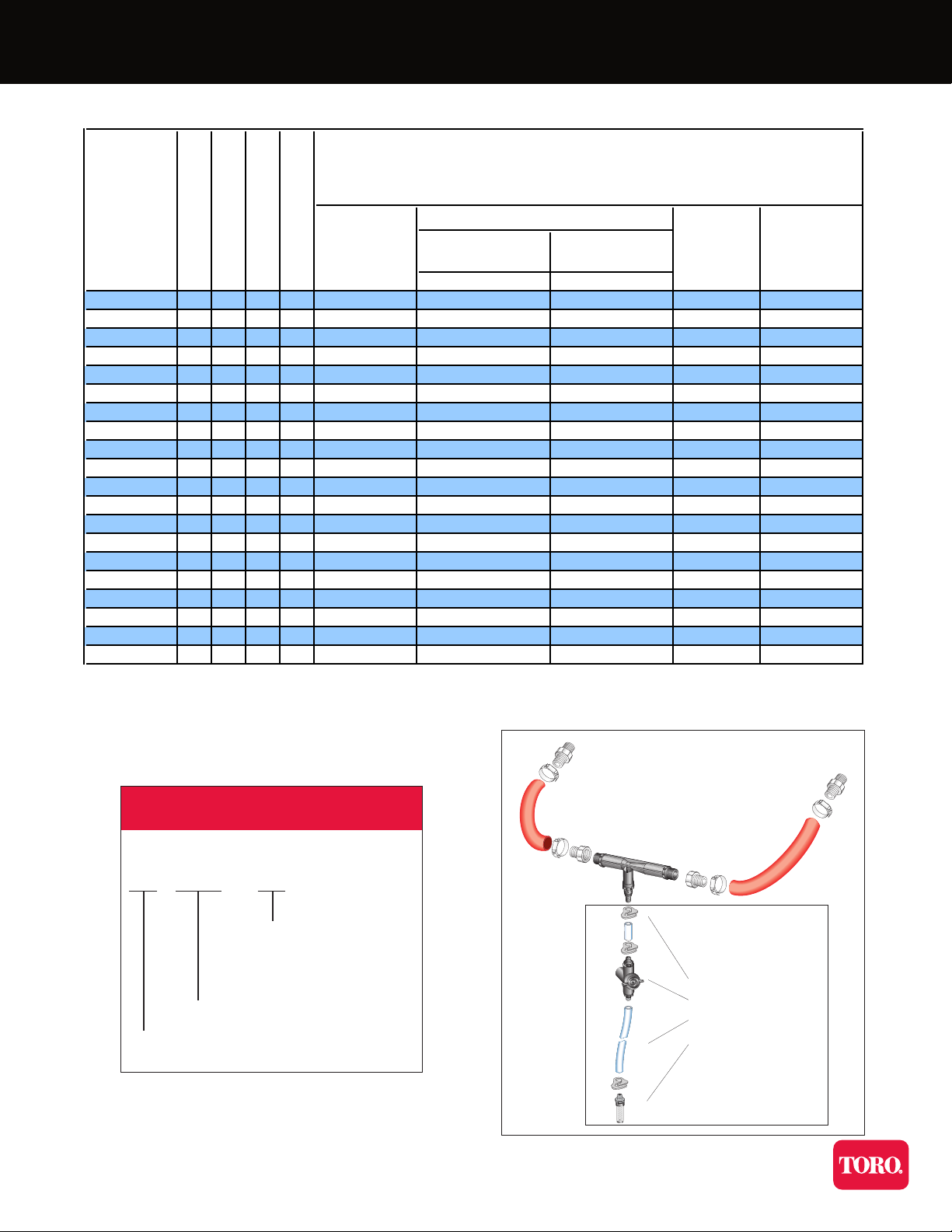
Injector Product Range
I
njector Injector Suction Bypass &
Model Size Line Kit Suction
Numbers In/Out Only Line Kit
MNPT or BSPT
gph lph
283 x x 1/2" 6.0 gph 22.7 lph K-184 K-184-A
287 x x 1/2" 8.3 gph 31.4 lph K-184 K-184-A
384 x x 1/2" 14.1 gph 53.4 lph K-184 K-184-A
384X x x 1/2" 33.9 gph 128.4 lph K-184 K-184-A
484 x x 1/2" 17.4 gph 65.9 lph K-184 K-184-A
584C x x 1/2" 25.6 gph 96.9 lph K-184 K-184-A
484A x x x 3/4" 17.4 gph 65.9 lph K-184 K-184-B
484X x x 3/4" 41.7 gph 157.8 lph K-184 K-184-B
584 x x x x 3/4" 25.6 gph 96.9 lph K-184 K-184-B
684 x x 3/4" 25.0 gph 95.0 lph K-184 K-184-B
878-02 x x x 1.0" 74.8 gph 283 lph K-183 K-181-A 02
885X-02 x x x x 1.0" 140 gph 530 lph K-183 K-181-A 02
1078-02 x x x x 1.0" 92.4 gph 350 lph K-183 K-181-A 02
1583A x x x x 1.5" 227 gph 860 lph K-183 K-183-A
1585X x x x 1.5" 323 gph 1222 lph K-183 K-183-A
1587 x x x 1.5" 261 gph 988 lph K-183 K-183-A
2081A x x x x 2.0" 631.0 gph 2388 lph K-282 K-282-A
2083X x x x 2.0" 1175.0 gph 4448 lph K-282 K-282-A
3090 x x 3.0" 1236 gph 4678 lph N/A N/A
4091 x x 4.0" 2820 gph 10673 lph N/A N/A
* Bypass and suction line kit combination is not available with BSPT threads for 1" and larger injectors
** 1/2" NPT threads are compatible with 1/2" BSPT threads
*** The 1" injectors ending with part number 02 have a new check valve design the same as the 1 1/2" injectors
NPT Polypropylene Black
NPT PVDF Black
Injector Models and Kit Assemblies
Maximum Suction Capacity
BSPT Polypropylene Green
BSPT PVDF Blue
@ 50 psi
@ 3.4 bars
Bypass and Suction Line Kit:
Specifying Information
AIV1583A-P (1.5" MNPT black poly injector)
XXX XXXXX - XXX
Example part number:
(blank) PVDF (Kynar®)
P Polypropylene black
PPG Polypropylene green
Injector model number
Suction Line Kit:
1. Tubing clamp
2. Metering Valve
3. Tubing (10FT.)
AIV NPT threads
AIC BSPT threads
4. Strainer
Note: Injector not
included in the kits
Page 4
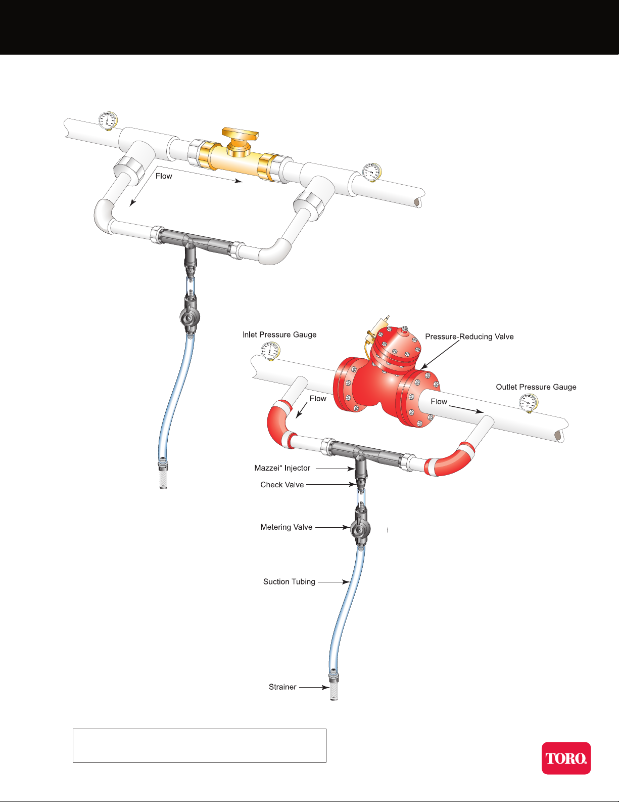
Typical Installations
Bypass installation
Note: Always consult state and local requirements
for backflow protection and chemical use
Injector installed around a
point of restriction such as a
regulator valve or gate valve
which creates a differential
pressure, thereby allowing the
injector to produce a vacuum.
Page 5

Typical Installations
Bypass with reduced pressure
differental requirement.
Chemical injection can be turned
on or off with a controller.
Injector installed across
the differential pressure
created by an existing
booster or supply pump
in the system. It is
plumbed from the
discharge side to the
intake side of the pump.
Booster pump installation
Page 6
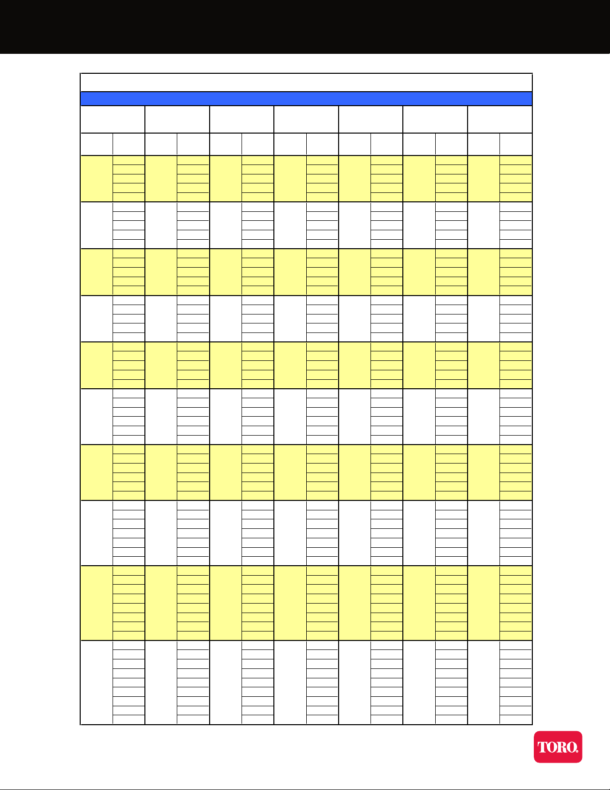
Performance Table
I
njector
Inlet
I
njector
Outlet
M
otive
Flow
G
PM
W
ater
Suction
G
PH
M
otive
Flow
G
PM
W
ater
Suction
G
PH
M
otive
Flow
G
PM
W
ater
Suction
G
PH
M
otive
Flow
G
PM
W
ater
Suction
G
PH
M
otive
Flow
G
PM
W
ater
Suction
G
PH
M
otive
Flow
G
PM
W
ater
Suction
G
PH
03.25.210.311.714.623.5
12.02.68.78.710.516.7
21.11.87.54.06.711.9
3 1.25.1 1.07.4
4
(
3.5)
(
3.5)
(
3.9) (2.9) (4.4) (3.5)
0
4.7 6.2 15.3 17.5 18.8 29.8
22.84.811.513.614.023.1
51.21.97.62.06.111.9
7 0.8 2.1 2.8 3.8
8
(
7.0)
(
7.7)
(
8.2) (6.6) (8.4) (7.5)
05.46.813.427.818.838.7
52.74.111.411.711.421.0
71.72.98.54.28.315.7
1
01.34.91.0
12
(10.5) (11.5)
(12.9) (9.6) (12.5) (9.6)
05.87.013.129.718.039.5
53.76.113.217.215.727.7
10 2.0 3.4 9.3 3.0 9.5 13.4
12 0.6 1.9 6.4 7.8 8.4
15
(15.0)
(16.0)
0.5
(16.5)
2.5
(12.4) (17.0)
1.0
(13.2)
05.97.814.233.117.939.6
54.86.914.322.417.332.1
10 2.6 4.4 12.7 11.2 13.8 22.0
15 0.7 2.3 6.7 7.4 9.9
20
(18.5)
(19.5)
(20.5) (15.0) (21.6)
1.0
(16.5)
06.08.014.233.917.239.8
55.87.914.424.717.038.1
10 3.8 5.6 13.9 17.3 16.6 28.8
15 2.4 3.6 10.7 7.0 11.3 17.0
20 0.8 1.7 4.5 7.1
25
(22.5)
(24.5)
(25.2) (18.0) (25.5) (19.8)
06.08.114.533.817.340.3
56.08.014.529.117.439.3
10 4.8 6.8 14.5 19.2 17.4 33.9
15 3.4 5.0 13.7 10.7 17.4 24.3
20 1.7 3.0 9.4 11.1 14.8
25
(26.0)
0.6
(27.0)
1.1
(28.6)
3.0
(20.8) (29.5)
4.0
(23.5)
06.08.114.234.017.140.8
56.08.114.231.617.738.7
10 5.5 7.4 14.0 24.1 17.7 38.5
15 4.2 6.3 14.0 14.3 17.7 29.9
20 2.6 4.3 12.6 3.6 15.2 20.7
25 1.2 2.7 7.5 11.4 6.5
30
(29.5)
(31.0)
0.3
(32.0)
2.0
(22.8) (33.3)
4.0
(26.1)
06.08.113.733.917.241.4
56.08.113.831.617.239.1
10 5.8 8.1 13.8 30.8 17.5 37.9
15 4.9 6.9 13.7 19.0 17.5 35.0
20 3.4 5.5 13.8 11.1 16.7 26.9
25 2.7 4.0 12.2 1.4 13.9 18.2
30 1.0 2.4 6.1 10.3
35
(33.5)
(35.0)
(36.1) (26.1) (36.8)
3.7
(29.6)
06.08.314.133.917.441.7
56.08.314.132.817.440.5
10 6.0 8.3 14.1 31.7 17.7 39.2
15 5.7 8.0 14.1 25.3 17.7 37.4
20 4.7 5.9 13.6 15.2 17.7 29.5
25 3.5 4.5 13.6 6.7 16.5 20.3
30 2.1 3.0 10.1 12.7 8.2
35 0.7 1.2 6.1 7.8
40
(37.0)
(39.0)
(39.6) (28.7) (41.0) (32.6)
1.21
.2
5
10
0
.170.290.70.7
0.24
0.32
** Numbers in parenthesis indicate the injector outlet pressure when suction stops (Zero Suction Point). **
1.7
2.1
1.7
50
45
25
30
35
15
Injector Performance Table
Water Suction Capacity • Injector Inlet Pressure 5-50 PSIG
Model 384X
Model 484
Model 484X
Model 283
Model 287
Model 384
O
perating Pressure
P
SIG
1
/2" & 3/4" Threads
1.0
1.0
1.2
1.9
1.9
20
40
0.35
0.41
2.1
0.32
0.51
1.4
1.4
2.4
2.4
0.28
1.2
0.42
2.7
0.39
0.65
1.7
1.7
2.9
2.9
0.58
1.6
1.6
3.2
0.43
0.75
2.0
2.0
3.4
3.4
0.70
2.7
2.1
2.1
3.6
3.2
3.6
0.48
0.85
2.2
2.2
3.8
3.8
0.46
0.81
3
/4" Threads
1
/2" Threads
1
/2" Threads
1
/2" Threads
1
/2" Threads
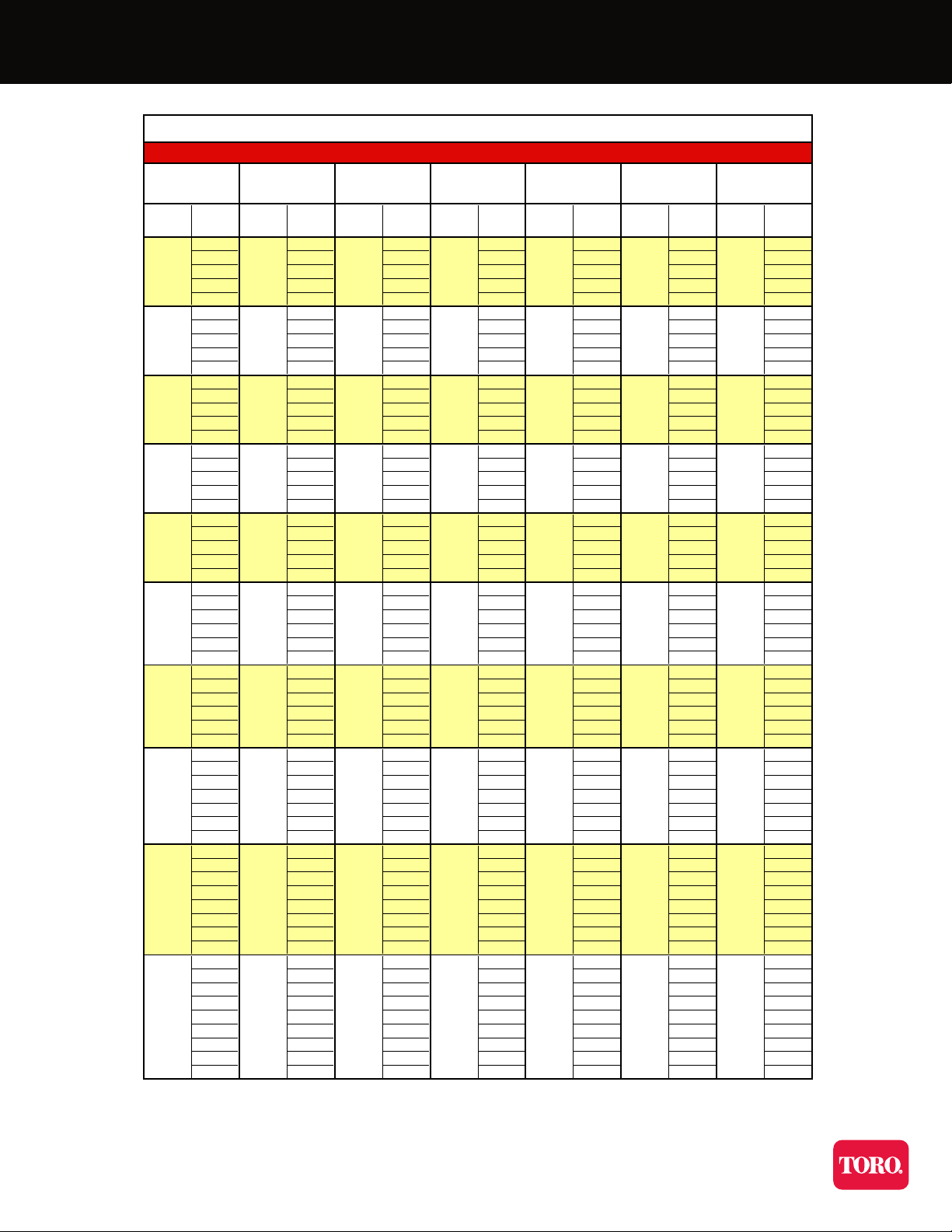
Page 7

Performance Table
I
njector
Inlet
I
njector
Outlet
M
otive
Flow
G
PM
W
ater
Suction
G
PH
M
otive
Flow
G
PM
W
ater
Suction
G
PH
M
otive
Flow
G
PM
W
ater
Suction
G
PH
M
otive
Flow
G
PM
W
ater
Suction
G
PH
M
otive
Flow
G
PM
W
ater
Suction
G
PH
M
otive
Flow
G
PM
W
ater
Suction
G
PH
029.227.462.978.1101.5135.8
128.920.336.162.646.484.5
228.513.823.842.722.253.3
325.46.67.315.52.7
4
(
4.4)
10.0
(
4.3)
5.6
(
4.0)
1.7
(
4.0) (4.0) (4.4)
0
28.3 27.2 93.8 115.9 105.8 219.9
228.227.362.090.875.7143.8
527.518.536.544.841.878.8
713.310.915.819.419.242.0
8
(
9.0)
11.0
(
8.5)
6.1
(
8.7)
3.7
(
7.5) (8.1)
4.4
(
8.6)
028.226.187.4135.3101.3225.2
527.926.162.183.279.9163.8
728.025.145.558.064.7124.4
1
014.012.923.619.234.386.5
12
(13.5)
11.0
(13.0)
7.0
(12.5)
7.2
(11.0) (13.1)
17.0
(13.0)
14.6
024.825.182.9141.998.2228.0
524.825.280.5117.495.4205.4
10 23.7 25.2 48.6 57.7 70.0 143.5
12 19.2 18.4 33.6 36.2 51.5 131.7
15
(18.0)
14.6
(16.5)
10.4
(16.5)
21.0
(14.0) (17.3)
30.3
(17.9)
66.2
025.224.882.3142.796.0226.8
525.224.981.3135.896.7226.4
10 25.1 24.9 73.2 96.5 89.4 193.9
15 20.8 24.4 45.3 38.4 68.2 148.1
20
(22.0)
12.2
(21.0)
5.2
(21.0)
20.1
(17.0) (21.9)
31.9
(22.1)
49.0
025.324.579.9144.194.4226.5
525.424.679.2140.794.5226.4
10 24.9 24.6 77.0 125.3 94.5 211.6
15 25.2 24.6 65.4 69.3 82.1 167.3
20 18.2 14.7 35.4 14.3 55.4 125.5
25
(27.0)
11.6
(26.0)
6.8
(26.1)
9.1
(20.5) (26.0)
17.9
(26.0)
18.3
025.524.779.4142.494.0226.7
525.524.679.4141.794.0226.5
10 25.4 24.7 77.5 135.7 94.0 224.2
15 25.3 24.8 74.5 106.7 91.9 205.7
20 21.9 24.9 52.3 54.2 74.1 164.8
25
(31.5)
16.5
(29.5)
12.9
(30.1)
30.3
(24.0) (30.0)
47.3
(29.4)
89.1
025.625.077.5141.093.2227.3
525.625.077.5141.193.2228.7
10 25.6 25.1 77.5 139.1 93.2 227.2
15 25.5 25.0 77.5 128.0 93.2 220.5
20 25.2 25.1 73.6 90.5 91.9 192.8
25 21.3 24.7 50.6 36.9 72.2 153.4
30
(35.5)
15.0
(35.0)
10.8
(34.4)
28.2
(27.0) (34.4)
42.7
(33.4)
81.5
025.925.079.6140.992.8227.9
526.025.079.6139.792.8228.3
10 26.0 25.0 79.6 139.2 92.8 228.0
15 25.9 25.1 79.6 134.8 92.8 223.5
20 25.7 25.1 78.8 112.1 93.9 212.4
25 23.6 25.1 67.0 74.5 86.9 174.9
30 19.4 20.6 44.2 23.2 66.2 113.1
35
(40.0)
13.5
(37.5)
8.4
(38.4)
22.0
(31.0) (38.7)
36.7
(37.5)
47.1
025.625.074.8139.692.4227.4
525.625.074.8140.592.4227.4
10 25.6 25.0 74.8 140.5 92.4 226.3
15 25.5 25.1 74.8 139.1 92.4 225.6
20 25.4 24.9 74.8 128.1 92.4 224.4
25 24.5 25.0 68.3 106.8 92.4 203.7
30 21.6 17.1 56.2 59.0 86.4 172.4
35 15.8 9.2 36.6 12.9 64.3 120.6
40
(45.0)
2.8
(42.0)
6.7
(42.3)
9.6
(36.0) (43.9)
35.0
(41.9)
40.5
5.5
9.3
1
" Threads
1
" Threads
5.1
8.6
9.0
8.7
1
" Threads
1
.5" Threads
14.5
28.4
21.5
** Numbers in parenthesis indicate the injector outlet pressure when suction stops (Zero Suction Point). **
32.2
6.6
11.1
11.6
11.3
11.0
10.7
6.3
10.5
17.3
33.9
5.9
9.9
10.3
10.1
15.5
30.3
9.7
9.4
7.1
11.0
8.0
3.6
4.7
7.8
8.2
3.65.51
0.7
3.0
5.0
5.2
5.0
7.7
15.2
Model 1078
Water Suction Capacity • Injector Inlet Pressure 5-50 PSIG
Model 1583A
12.2
24.0
Model 885X
3.53.76.1
6.3
15
13.4
26.3
16.4
6.2
9.5
18.6
4.2
7.0
7.3
10
Model 584
Model 684
2
.1
O
perating Pressure
P
SIG
1
/2" & 3/4" Threads
3
/4" Threads
Injector Performance Table
50
45
25
30
35
20
40
Model 878
5
Page 8

Performance Table
I
njector
I
nlet
I
njector
O
utlet
M
otive
Flow
G
PM
W
ater
Suction
G
PH
M
otive
Flow
G
PM
W
ater
Suction
G
PH
M
otive
Flow
G
PM
W
ater
Suction
G
PH
M
otive
Flow
G
PM
W
ater
Suction
G
PH
M
otive
Flow
G
PM
W
ater
Suction
G
PH
M
otive
Flow
G
PM
W
ater
Suction
G
PH
0123.5244.363045610502100
174.8102.96301589001500
226.391.5630 7561200
354.2215456840
4
(
3.5) (4.1) (4.5)
136
(
1.4) (4.0) (4.5)
360
0241.5269.763056114462820
2
155.9 249.1 630 154 1446 2820
543.4103.7468 8701860
758.3149396780
8
(
6.5) (8.7)
14.4
(
9.0)
30
(
2.4) (8.5) (8.8)
240
0262.0270.663167114342820
5157.7184.7623 14282820
786.6154.2576 10442280
10 98.6 213 552 720
12
(9.4) (13.5)
38.0
(13.3)
77
(3.7) (13.5)
300
(13.1)
360
0308.6267.163175714162820
5231.9265.763123714162820
10 120.2 174.6 468 1170 2700
12 39.3 142.0 299 792 1800
15
(12.7) (17.0)
88.0
(17.5)
152
(5.7) (17.0)
432
(17.5)
720
0324.6265.263181213442820
5275.5264.963142913442820
10 204.5 229.6 627 1356 2820
15 50.5 156.8 404 930 1980
20
(15.4) (22.1)
55.1
(22.3)
134
(7.1) (21.5)
114
(21.7)
420
0323.1263.563184913082820
5299.7261.563178013082820
10 251.2 268.3 631 1308 2820
15 137.5 200.4 511 1284 2580
20 164.8 341 576 1380
25
(19.3) (25.6)
33.4
(26.0)
62
(8.8) (25.5) (26.0)
240
0326.3285.763185312902820
5318.1284.763167012902820
10 286.7 287.7 631 288 1266 2820
15 204.1 251.8 627 1266 2820
20 66.7 191.7 460 906 2640
25
(22.4) (29.0)
143.8
(30.5)
256
(10.4) (29.5)
396
(30.5)
1440
0324.3287.063189712542820
5321.3284.963192012542820
10 307.8 282.6 631 389 1254 2820
15 257.1 278.4 631 1254 2820
20 146.6 244.5 524 1110 2820
25 11.9 180.3 394 714 1860
30
(25.5) (33.2)
115.5
(33.5)
169
(11.6) (32.5)
228
(35.0)
900
0326.0259.863194812602820
5324.1259.263174912602820
10 318.1 260.4 631 486 1260 2820
15 287.2 257.1 631 1260 2820
20 210.2 256.9 607 1200 2820
25 106.9 225.9 508 960 2820
30 157.1 341 582 2400
35
(28.7) (38.3)
73.5
(38.0)
149
(13.4) (36.0) (38.9)
960
0323.0260.5631117512362820
5319.3259.7631127812362820
10 315.5 259.7 631 579 1236 2820
15 296.7 258.3 631 1236 2820
20 251.8 257.3 631 1236 2820
25 156.8 252.4 588 1194 2820
30 45.4 205.4 453 882 2640
35 137.2 300 498 1620
40
(32.4) (41.0)
75.1
(41.5)
115
(14.4) (40.5) (43.1)
360
242
416
32.2
53.1
103
33.9
56.0
108
28.6
28.4
46.8
91
402
30.3
50.09726.4
24.0
39.67721.8
26.3
43.38423.1
1701
5.225.04813.1108214
Water Suction Capacity • Injector Inlet Pressure 5-50 PSIG
M
odel
4091
171
307
M
odel
2083X
1
7.734
30.7598.418.9
153
272
27.7
202
24.4
360
216
382
M
odel
1587
1
0.7
15
187
21.5
35.4
68
M
odel
3090
7618.6
** Numbers in parenthesis indicate the injector outlet pressure when suction stops (Zero Suction Point). **
1
.5" Threads
2
" Threads
2
" Threads
3
" Threads
332
229
16.1
132
251
5
10
M
odel
1585X
O
perating Pressure
P
SIG
1
.5" Threads
Injector Performance Table
50
45
25
30
35
20
40
M
odel
2081
4
" Threads
Page 9
Performance Table – metric
Injector
Inlet
Injector
Outlet
Motive
Flow
l
/min.
Water
Suction
l
/min.
Motive
Flow
l
/min.
Water
Suction
l
/min.
Motive
Flow
l
/min.
Water
Suction
l
/min.
Motive
Flow
l
/min.
Water
Suction
l
/min.
Motive
Flow
l
/min.
Water
Suction
l
/min.
Motive
Flow
l
/min.
Water
Suction
l
/min.
0.00 0.20 0.33 0.65 0.74 0.92 1.48
0.07 0.13 0.16 0.55 0.55 0.66 1.05
0.14 0.07 0.11 0.47 0.25 0.42 0.75
0.21 0.08 0.32 0.06 0.46
0.28
(0.25)
(0.25) (0.27) (0.20) (0.31) (0.25)
0.00 0.30 0.39 0.97 1.11 1.18 1.88
0.14 0.18 0.30 0.73 0.86 0.88 1.46
0
.35 0.08 0.12 0.48 0.38 0.75
0.49 0.05 0.13 0.18 0.24
0
.56
(0.49)
(0.54) (0.58) (0.46) (0.59) (0.53)
0.00 0.34 0.43 0.84 1.75 1.18 2.44
0.35 0.17 0.26 0.72 0.74 0.72 1.32
0.49 0.11 0.18 0.53 0.26 0.52 0.99
0.70 0.08 0.31 0.06
0.84
(
0.74) (0.81) (0.91) (0.68) (0.88) (0.68)
0.00 0.37 0.44 0.82 1.87 1.14 2.49
0.35 0.23 0.38 0.83 1.08 0.99 1.74
0.70 0.13 0.21 0.58 0.19 0.60 0.84
0
.84 0.04 0.12 0.40 0.49 0.53
1.05
(1.06)
(1.13)
0.03
(1.16)
0.16
(0.87) (1.20)
0.06
(0.93)
0.00 0.37 0.49 0.89 2.09 1.13 2.50
0.35 0.30 0.44 0.90 1.41 1.09 2.03
0.70 0.16 0.28 0.80 0.71 0.87 1.39
1.05 0.04 0.15 0.42 0.47 0.63
1.41
(1.30)
(1.37) (1.44) (1.06) (1.52)
0.06
(1.16)
0.00 0.38 0.50 0.90 2.14 1.09 2.51
0.35 0.37 0.50 0.91 1.56 1.08 2.41
0.70 0.24 0.35 0.88 1.09 1.05 1.82
1.05 0.15 0.23 0.68 0.44 0.71 1.07
1.41 0.05 0.11 0.29 0.45
1.76
(1.58)
(1.72) (1.77) (1.27) (1.79) (1.39)
0.00 0.38 0.51 0.91 2.13 1.09 2.54
0.35 0.38 0.50 0.91 1.83 1.10 2.48
0.70 0.30 0.43 0.91 1.21 1.10 2.14
1.05 0.21 0.32 0.87 0.68 1.10 1.53
1.41 0.11 0.19 0.59 0.70 0.93
1.76
(1.83)
0.04
(1.90)
0.07
(2.01)
0.19
(1.46) (2.07)
0.25
(1.65)
0.00 0.38 0.51 0.89 2.14 1.08 2.57
0.35 0.38 0.51 0.89 1.99 1.12 2.44
0.70 0.35 0.47 0.88 1.52 1.12 2.43
1.05 0.26 0.40 0.88 0.90 1.12 1.89
1.41 0.16 0.27 0.80 0.22 0.96 1.31
1.76 0.08 0.17 0.47 0.72 0.41
2.11
(2.07)
(2.18)
0.02
(2.25)
0.13
(1.60) (2.34)
0.25
(1.84)
0.00 0.38 0.51 0.87 2.14 1.09 2.61
0.35 0.38 0.51 0.87 2.00 1.09 2.46
0.70 0.37 0.51 0.87 1.94 1.10 2.39
1.05 0.31 0.44 0.87 1.20 1.10 2.21
1.41 0.21 0.35 0.87 0.70 1.05 1.70
1.76 0.17 0.25 0.77 0.09 0.87 1.15
2.11 0.06 0.15 0.39 0.65
2.46
(2.36)
(2.46) (2.54) (1.84) (2.59)
0.23
(2.08)
0.00 0.38 0.52 0.89 2.14 1.10 2.63
0.35 0.38 0.52 0.89 2.07 1.10 2.55
0.70 0.38 0.52 0.89 2.00 1.12 2.47
1.05 0.36 0.50 0.89 1.60 1.12 2.36
1.41 0.30 0.37 0.86 0.96 1.12 1.86
1.76 0.22 0.28 0.86 0.42 1.04 1.28
2.11 0.13 0.19 0.64 0.80 0.52
2.46 0.04 0.08 0.38 0.49
2.81
(2.60)
(2.74) (2.78) (2.02) (2.88) (2.29)
** Numbers in parenthesis indicate the injector outlet pressure when suction stops (Zero Suction Point). **
13.55
13.55
1.82
3.22
8.48
8.48
14.27
14.27
1.74
3.07
8.06
8.06
11.96
12.76
12.76
2.65
7.12
11.96
7.12
2.84
7.61
7.61
5.37
2.20
6.59
6.02
1.93
5.37
6.02
9.01
4.66
11.05
10.11
11.05
9.01
7.83
10.11
7.83
2.46
6.59
1
.213.79
1.59
2.69
1.10
2.69
6
.403.79
1.41
2.81
1.32
1.55
1.48
1.21
1.63
0
.35
0.70
4.66
1.05
1.06
3.52
3.16
1.76
2.11
2.46
M
odel
283
0.64
0
.91
Injector Performance Table
Water Suction Capacity • Injector Inlet Pressure 0.35-3.52 Kg/cm
2
M
odel
384X
M
odel
484
M
odel
484X
M
odel
287
M
odel
384
Operating Pressure
Kg/cm
2
1/2" Threads
1/2" Threads
6
.40
4.50
4.50
1/2" Threads
1/2" Threads
1/2" & 3/4" Threads
3/4" Threads
Page 10

Performance Table – metric
Injector
I
nlet
Injector
O
utlet
Motive
Flow
l/min.
Water
Suction
l/min.
Motive
Flow
l/min.
Water
Suction
l/min.
Motive
Flow
l/min.
Water
Suction
l/min.
Motive
Flow
l/min.
Water
Suction
l/min.
Motive
Flow
l/min.
Water
Suction
l/min.
Motive
Flow
l/min.
Water
Suction
l/min.
0.00 1.84 1.73 3.97 4.92 6.40 8.57
0.07 1.82 1.28 2.28 3.95 2.93 5.33
0.14 1.80 0.87 1.50 2.69 1.40 3.36
0.21 1.60 0.42 0.46 0.98 0.17
0.28
(0.31)
0.63
(0.30)
0.35
(0.28)
0.11
(0.28) (0.28) (0.31)
0
.00 1.78 1.72 5.92 7.31 6.67 13.87
0
.14 1.78 1.72 3.91 5.73 4.78 9.07
0.35 1.73 1.17 2.30 2.82 2.64 4.97
0.49 0.84 0.69 1.00 1.22 1.21 2.65
0
.56
(
0.63)
0
.69
(
0.60)
0
.38
(
0.61)
0
.23
(
0.53) (0.57)
0
.28
(
0.61)
0.00 1.78 1.65 5.51 8.54 6.39 14.21
0.35 1.76 1.65 3.92 5.25 5.04 10.33
0.49 1.77 1.58 2.87 3.66 4.08 7.85
0.70 0.88 0.81 1.49 1.21 2.16 5.46
0.84
(
0.95)
0.70
(
0.91)
0.44
(
0.88)
0.45
(
0.77) (0.92)
1.07
(
0.91)
0.92
0.00 1.57 1.59 5.23 8.95 6.20 14.39
0.35 1.57 1.59 5.08 7.40 6.02 12.96
0.70 1.50 1.59 3.07 3.64 4.42 9.06
0
.84 1.21 1.16 2.12 2.28 3.25 8.31
1.05
(1.27)
0.92
(1.16)
0.66
(1.16)
1.33
(0.98) (1.22)
1.91
(1.26)
4.18
0.00 1.59 1.57 5.19 9.00 6.05 14.31
0.35 1.59 1.57 5.13 8.56 6.10 14.28
0.70 1.59 1.57 4.62 6.09 5.64 12.23
1.05 1.31 1.54 2.86 2.42 4.30 9.34
1.41
(1.55)
0.77
(1.48)
0.33
(1.48)
1.27
(1.20) (1.54)
2.01
(1.55)
3.09
0.00 1.60 1.55 5.04 9.09 5.95 14.29
0.35 1.60 1.55 5.00 8.88 5.96 14.28
0.70 1.57 1.55 4.86 7.90 5.96 13.35
1.05 1.59 1.55 4.12 4.37 5.18 10.55
1.41 1.15 0.93 2.23 0.91 3.50 7.92
1.76
(1.90)
0.73
(1.83)
0.43
(1.84) (1.44) (1.83)
1.13
(1.83)
1.15
0.00 1.61 1.56 5.01 8.98 5.93 14.30
0.35 1.61 1.55 5.01 8.94 5.93 14.29
0.70 1.60 1.56 4.89 8.56 5.93 14.14
1.05 1.59 1.56 4.70 6.73 5.80 12.98
1.41 1.38 1.57 3.30 3.42 4.68 10.40
1.76
(2.22)
1.04
(2.07)
0.82
(2.12)
1.91
(1.69) (2.11)
2.98
(2.07)
5.62
0.00 1.62 1.57 4.89 8.89 5.88 14.34
0.35 1.61 1.58 4.89 8.90 5.88 14.43
0.70 1.62 1.59 4.89 8.77 5.88 14.33
1.05 1.61 1.58 4.89 8.08 5.88 13.91
1.41 1.59 1.58 4.64 5.71 5.79 12.17
1.76 1.35 1.56 3.19 2.33 4.56 9.68
2.11
(2.50)
0.95
(2.46)
0.68
(2.42)
1.78
(1.90) (2.42)
2.69
(2.35)
5.14
0.00 1.63 1.58 5.02 8.89 5.86 14.38
0.35 1.64 1.58 5.02 8.81 5.86 14.40
0.70 1.64 1.58 5.02 8.78 5.86 14.38
1.05 1.63 1.58 5.02 8.51 5.86 14.10
1.41 1.62 1.58 4.97 7.07 5.92 13.40
1.76 1.49 1.59 4.23 4.70 5.48 11.03
2.11 1.22 1.30 2.79 1.46 4.18 7.13
2.46
(2.81)
0.85
(2.64)
0.53
(2.70)
1.39
(2.18) (2.72)
2.32
(2.64)
2.97
0.00 1.61 1.58 4.72 8.81 5.83 14.35
0.35 1.61 1.58 4.72 8.86 5.83 14.35
0.70 1.61 1.58 4.72 8.86 5.83 14.28
1.05 1.61 1.58 4.72 8.77 5.83 14.23
1.41 1.60 1.57 4.72 8.08 5.83 14.16
1.76 1.54 1.57 4.31 6.73 5.83 12.85
2.11 1.36 1.08 3.54 3.72 5.45 10.88
2.46 0.99 0.58 2.31 0.82 4.06 7.61
2.81
(3.16)
0.18
(2.95)
0.42
(2.97)
0.60
(2.53) (3.09)
2.21
(2.95)
2.55
Injector Performance Table
M
odel
885X
M
odel
684
M
odel
878
Water Suction Capacity • Injector Inlet Pressure 0.35-3.52 Kg/cm
2
50.76
13.25
13.82
3/4" Threads
1" Threads
1" Threads
13.70
1" Threads
3.52
3.16
1.76
2.11
2.46
1.41
2.81
1.05
99.5
62.19
23.35
35.88
70.3
46.33
90.8
26.99
41.45
81.2
1
9.0829.3057.4
M
odel
1078
M
odel
1583A
13.47
20.74
40.6
1.5" Threads
0.70
M
odel
584
7.91
Operating Pressure
Kg/cm
2
1
1.20
1/2" & 3/4" Threads
0.35
1
8.7719.57
19.38
32.48
33.88
15.82
26.53
27.67
22.97
23.96
33.04
17.68
29.67
30.92
30.17
22.37
37.51
39.10
38.15
20.93
35.09
36.56
35.69
41.48
40.46
54.84
107.4
58.63
114.8
** Numbers in parenthesis indicate the injector outlet pressure when suction stops (Zero Suction Point). **
121.8
25.02
41.94
43.72
42.66
65.56
128.4
23.73
39.78
Page 11

Performance Table – metric
Injector
Inlet
Injector
Outlet
Motive
Flow
l/min.
Water
Suction
l/min.
Motive
Flow
l/min.
Water
Suction
l/min.
Motive
Flow
l/min.
Water
Suction
l/min.
Motive
Flow
l/min.
Water
Suction
l/min.
Motive
Flow
l/min.
Water
Suction
l/min.
Motive
Flow
l/min.
Water
Suction
l/min.
0.00 7.8 15.4 39.7 28.8 66.2 132.5
0.07 4.7 6.5 39.7 10.0 56.8 94.6
0.14 1.7 5.8 39.7 47.7 75.7
0
.21 3.4 13.5 28.8 53.0
0.28
(
0.25) (0.29) (0.32)
8.6
(
0.10) (0.28) (0.32)
22.7
0
.00 15.2 17.0 39.7 35.4 91.2 177.9
0.14 9.8 15.7 39.7 9.7 91.2 177.9
0
.35 2.7 6.5 29.5 54.9 117.3
0.49 3.7 9.4 25.0 49.2
0.56
(
0.46) (0.61)
0.9
(
0.63)
1.9
(
0.17) (0.60) (0.62)
15.1
0.00 16.5 17.1 39.8 42.4 90.5 177.9
0.35 10.0 11.7 39.3 90.1 177.9
0.49 5.5 9.7 36.4 65.9 143.8
0.70 6.2 13.4 34.8 45.4
0.84
(0.66) (0.95)
2.4
(0.94)
4.8
(0.26) (0.95)
18.9
(0.92)
22.7
0.00 19.5 16.8 39.8 47.8 89.3 177.9
0
.35 14.6 16.8 39.8 14.9 89.3 177.9
0.70 7.6 11.0 29.5 73.8 170.3
0.84 2.5 9.0 18.8 50.0 113.6
1.05
(0.89) (1.20)
5.5
(1.23)
9.6
(0.40) (1.20)
27.3
(1.23)
45.4
0.00 20.5 16.7 39.8 51.2 84.8 177.9
0.35 17.4 16.7 39.8 27.1 84.8 177.9
0.70 12.9 14.5 39.5 85.5 177.9
1.05 3.2 9.9 25.5 58.7 124.9
1.41
(1.08) (1.55)
3.5
(1.57)
8.5
(0.50) (1.51)
7.2
(1.53)
26.5
0.00 20.4 16.6 39.8 53.6 82.5 177.9
0.35 18.9 16.5 39.8 49.2 82.5 177.9
0.70 15.8 16.9 39.8 82.5 177.9
1.05 8.7 12.6 32.3 81.0 162.8
1.41 10.4 21.5 36.3 87.1
1.76
(1.36) (1.80)
2.1
(1.83)
3.9
(0.62) (1.79) (1.83)
15.1
0.00 20.6 18.0 39.8 53.8 81.4 177.9
0.35 20.1 18.0 39.8 42.3 81.4 177.9
0.70 18.1 18.1 39.8 18.2 79.9 177.9
1.05 12.9 15.9 39.5 79.9 177.9
1.41 4.2 12.1 29.0 57.2 166.5
1.76
(1.58) (2.04)
9.1
(2.14)
16.1
(0.73) (2.07)
25.0
(2.14)
90.8
0.00 20.5 18.1 39.8 56.6 79.1 177.9
0.35 20.3 18.0 39.8 58.0 79.1 177.9
0.70 19.4 17.8 39.8 24.5 79.1 177.9
1.05 16.2 17.6 39.8 79.1 177.9
1.41 9.2 15.4 33.0 70.0 177.9
1.76 0.8 11.4 24.9 45.0 117.3
2.11
(1.79) (2.33)
7.3
(2.36)
10.7
(0.82) (2.29)
14.4
(2.46)
56.8
0.00 20.6 16.4 39.8 59.8 79.5 177.9
0.35 20.4 16.4 39.8 47.2 79.5 177.9
0.70 20.1 16.4 39.8 30.6 79.5 177.9
1.05 18.1 16.2 39.8 79.5 177.9
1.41 13.3 16.2 38.3 75.7 177.9
1.76 6.7 14.3 32.0 60.6 177.9
2.11 9.9 21.5 36.7 151.4
2.46
(2.02) (2.69)
4.6
(2.67)
9.4
(0.94) (2.53) (2.74)
60.6
0.00 20.4 16.4 39.8 74.1 78.0 177.9
0.35 20.1 16.4 39.8 80.6 78.0 177.9
0.70 19.9 16.4 39.8 36.5 78.0 177.9
1.05 18.7 16.3 39.8 78.0 177.9
1.41 15.9 16.2 39.8 78.0 177.9
1.76 9.9 15.9 37.1 75.3 177.9
2.11 2.9 13.0 28.6 55.6 166.5
2.46 8.7 18.9 31.4 102.2
2.81
(2.28) (2.88)
4.7
(2.92)
7.3
(1.01) (2.85) (3.03)
22.7
** Numbers in parenthesis indicate the injector outlet pressure when suction stops (Zero Suction Point). **
1522
128.4
211.8
410
108.3
916
1575
121.8
200.9
389
104.8
765
1363
818
1446
867
177.2
343
92.4
114.8
189.4
366
99.9
82.5
81.2
134.0
259
1.41
2.81
Model 2081
60.9
99.5
164.0
317
87.4
107.4
224
Injector Performance Table
1.05
130
500
950
643
57.4
94.7
183
49.6
3.52
3.16
1.76
2.11
2.46
708
1257
647
1
.5" Threads
2
" Threads
409
810
31.8
288
71.5
70.3
116.0
2
" Threads
1162
40.6
579
1030
90.8
149.7
290
0.35
0.70
3
" Threads
4
" Threads
Operating Pressure
Kg/cm
2
1
.5" Threads
67.0
Model 1587
Model 1585X
Water Suction Capacity • Injector Inlet Pressure 0.35-3.52 Kg/cm
2
Model 4091
Model 2083X
Model 3090
Page 12

Emission Devices
Micro VI PC Emitters Aqua-Traxx PC
Irrigation Controllers
Jr Max MC E Total Control
Control Valves
700 Series Valve 600 Series Valve Sentinel Valve
©2012 The Toro Company
Micro-Irrigation Business
1588 N. Marshall Avenue, El Cajon, CA 92020-1523, USA
Tel: +1(800) 333-8125 or +1 (619) 562-2950
Fax: +1 (800) 892-1822 or +1 (619) 258-9973
toro.com
ALT032 08/08
 Loading...