

Page 1
CCR™ 3650 GTS® Snowthrower
Model No. 38517 —Serial No. 270000001 and Up
Introduction
R ead this infor mation carefully to lear n ho w to operate and
maintain y our product properly and to a v oid injur y and
product damag e . Y ou are responsible for operating the
product properly and safely .
Form No. 3355-426 Rev A
Operator's Manual
Warning
CALIFORNIA
Pr oposition 65 W ar ning
T he engine exhaust fr om this pr oduct contains
chemicals kno wn to the State of Calif or nia to cause
cancer , bir th defects, or other r epr oducti v e har m.
Y ou ma y contact T oro directly at www .T oro .com for
product and accessor y infor mation, help finding a dealer ,
or to register y our product.
W henev er y ou need ser vice , g en uine T oro par ts , or
additional infor mation, contact an A uthorized Ser vice
Dealer or T oro Customer Ser vice and ha v e the model and
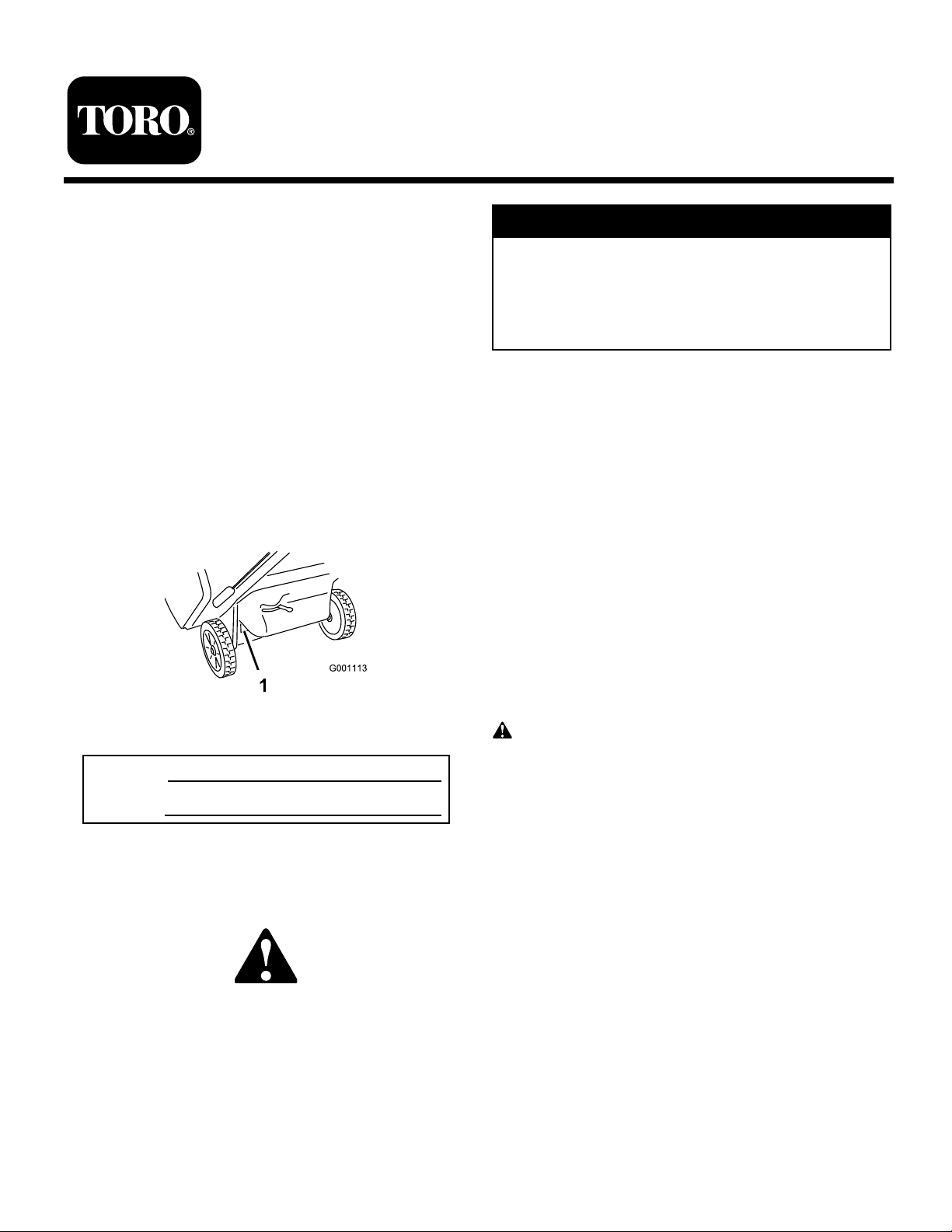
serial n umbers of y our product ready . Figure 1 identifies the
location of the model and serial n umbers on the product.
W rite the n umbers in the space pro vided.
Figure 1
1. Model and serial number location
Model No.
Serial No.
T his man ual identifies potential hazards and has safety
messag es identified b y the safety aler t symbol ( Figure 2 ),
whic h signals a hazard that ma y cause serious injur y or
death if y ou do not follo w the recommended precautions .
T his spark ignition system complies with Canadian
ICES-002
T he enclosed Engine Owner’ s Man ual is supplied
f or inf or mation r egarding the US En vir onmental
Pr otection Agency (EP A) and the Calif or nia Emission
Contr ol R egulation of emission systems, maintenance,
and w ar ranty . R eplacements may be order ed thr ough
the engine man uf actur er .
Safety
T his sno wthr o w er meets or ex ceeds the B71.3
specifications of the American National Standards
Institute in ef fect at the time of pr oduction.
R ead and under stand the contents of this man ual
bef or e the engine is ev er star ted.
T his is the safety aler t symbol. It is used to aler t y ou
to potential per sonal injur y hazards. Obey all safety
messa ges that f ollo w this symbol to a v oid possible
injur y or death.
Impr oper l y using or maintaining this sno wthr o w er
could r esult in injur y or death. T o r educe this potential,
compl y with the f ollo wing safety instr uctions.
T his sno w thro w er is capable of amputating hands and
feet and thro wing objects . F ailure to obser v e the follo wing
safety instr uctions could result in serious injur y .
Figure 2
1. Safety alert symbol
T his man ual uses 2 other w ords to highlight infor mation.
Impor tant calls attention to special mec hanical infor mation
and Note emphasizes g eneral infor mation w or th y of special
attention.
© 2006—The Toro® Company
8111 Lyndale Avenue South
Bloomington, MN 55420
Training
• R ead, understand and follo w all instr uctions on the
mac hine and in the man ual(s) before operating this unit.
Be thoroughly familiar with the controls and the proper
use of the equipment. Kno w ho w to stop the unit and
diseng ag e the controls quic kly .
• Nev er allo w c hildren to operate the equipment. Nev er
allo w adults to operate the equipment without proper
instr uction.
Register at www.Toro.com. Original Instructions (EN)
Printed in the USA
All Rights Reserved
Page 2

• K ee p the area of operation clear of all persons ,
par ticularly small c hildren.
• Ex ercise caution to a v oid slipping or falling, especially
when operating the sno w thro w er in rev erse .
Preparation
• T horoughly inspect the area where the equipment is to
be used and remo v e all door mats , sleds , boards , wires ,
and other foreign objects .
• Do not operate the equipment without w earing
adequate winter g ar ments . A v oid loose fitting clothing
that can g et caught in mo ving par ts . W ear footw ear that
will impro v e footing on slipper y surfaces .
• Handle fuel with care; it is highly flammable .
– Use an appro v ed fuel container .
– Nev er add fuel to a r unning engine or hot engine .
– Fill fuel tank outdoors with extreme care . Nev er fill
fuel tank indoors .
– Nev er fill containers inside a v ehicle or on a tr uc k
or trailer bed with a plastic liner . Alw a ys place
containers on the g round, a w a y from y our v ehicle ,
before filling .
– W hen practical, remo v e g as-po w ered equipment
from the tr uc k or trailer and refuel it on the g round.
If this is not possible , then refuel suc h equipment
on a trailer with a por table container , rather than
from a g asoline dispenser nozzle .
– K ee p the nozzle in contact with the rim of the fuel
tank or container opening at all times , until refueling
is complete . Do not use a nozzle loc k-open device .
– R e place g asoline cap securely and wipe up spilled
fuel.
– If fuel is spilled on clothing, c hang e clothing
immediately .
• Use extension cords and rece ptacles as specified b y the
man ufacturer for all units with electric star ting motors .
• Nev er attempt to mak e any adjustments while the engine
is r unning (ex ce pt when specifically recommended b y
man ufacturer).
• Alw a ys w ear safety glasses or eye shields during
operation or while perfor ming an adjustment or re pair
to protect eyes from foreign objects that ma y be thro wn
from the mac hine .
• Ex ercise extreme caution when operating on or crossing
g ra v el dri v es , w alks , or roads . Sta y aler t for hidden
hazards or traffic .
• After striking a foreign object, stop the engine , remo v e
the ignition k ey , thoroughly inspect the sno w thro w er
for any damag e , and re pair the damag e before restar ting
and operating the sno w thro w er .
• If the unit should star t to vibrate abnor mally , stop the
engine and c hec k immediately for the cause . Vibration
is g enerally a w ar ning of trouble .
• Stop the engine whenev er y ou lea v e the operating
position, before unclog ging the rotor blades or
disc harg e c hute , and when making any re pairs ,
adjustments or inspections .
• W hen cleaning, re pairing or inspecting the sno w
thro w er , stop the engine and mak e cer tain the rotor
blades and all mo ving par ts ha v e stopped. Disconnect
the spark plug wire and k ee p the wire a w a y from the
plug to prev ent someone from accidentally star ting the
engine .
• Do not r un the engine indoors , ex ce pt when star ting
the engine and for transpor ting the sno w thro w er in or
out of the building . Open the outside doors; exhaust
fumes are dang erous .
• Ex ercise extreme caution when operating on slopes .
• Nev er operate the sno w thro w er without proper guards ,
and other safety protecti v e devices in place and w orking .
• Nev er direct the disc harg e to w ard people or areas where
proper ty damag e can occur . K ee p c hildren and others
a w a y .
• Do not o v erload the mac hine capacity b y attempting to
clear sno w at too fast a rate .
• Nev er operate the mac hine at high transpor t speeds
on slipper y surfaces . Look behind and use care when
operating in rev erse .
• Diseng ag e po w er to the rotor blades when sno w
thro w er is transpor ted or not in use .
• Nev er operate the sno w thro w er without g ood visibility
or light. Alw a ys be sure of y our footing, and k ee p a fir m
hold on the handles . W alk; nev er r un.
• Nev er touc h a hot engine or m uffler .
Operation
• Do not put hands or feet near or under rotating par ts .
K ee p clear of the disc harg e opening at all times .
2
Page 3

Clearing a Clogged Discharge
Chute
Hand contact with the rotating rotor blades inside the
disc harg e c hute is the most common cause of injur y
associated with sno w thro w ers . Nev er use y our hand to
clean out the disc harg e c hute . T o clear the c hute:
• Shut the engine of f !
• W ait 10 seconds to be sure the rotor blades ha v e
stopped rotating .
• Alw a ys use a clean-out tool, not y our hands .
Maintenance and Storage
• Chec k all fasteners at frequent inter v als for proper
tightness to be sure the equipment is in safe w orking
condition.
• Nev er store the mac hine with fuel in the fuel tank inside
a building where ignition sources are present suc h as hot
w ater heaters , space heaters , or clothes dr yers . Allo w
the engine to cool before storing in any enclosure .
• Alw a ys refer to the Operator’ s Manual for impor tant
details if the sno w thro w er is to be stored for an
extended period.
• Do not touc h the engine while it is r unning or soon
after it has stopped because the engine ma y be hot
enough to cause a bur n.
• P erfor m only those maintenance instr uctions described
in this man ual. Before perfor ming any maintenance ,
ser vice , or adjustment, stop the engine , remo v e the
k ey , and disconnect the wire from the spark plug . If
major re pairs are ev er needed, contact y our A uthorized
Ser vice Dealer .
• Do not c hang e the g o v er nor settings on the engine .
• W hen storing the sno wthro w er for more than 30 da ys ,
drain the fuel from the fuel tank to prev ent a potential
hazard. Store fuel in an appro v ed fuel container .
R emo v e the k ey from the ignition switc h before storing
the sno wthro w er .
• Purc hase only g en uine T oro re placement par ts and
accessories .
• Maintain or re place safety and instr uction labels , as
necessar y .
• R un the mac hine a few min utes after thro wing sno w to
prev ent freeze-up of the rotor blades .
Toro Snowthrower Safety
T he follo wing list contains safety infor mation specific to
T oro products or other safety infor mation that y ou m ust
kno w .
• R otating r otor blades can injur e finger s or hands.
Sta y behind the handles and a w a y from the disc harg e
opening while operating the sno wthro w er . K eep y our
f ace, hands, feet, and an y other par t of y our body or
clothing a w ay fr om mo ving or r otating par ts.
• Before adjusting, cleaning, re pairing, and inspecting
the sno wthro w er , and before unclog ging the disc harg e
c hute , stop the engine, r emo v e the k ey , and w ait f or
all mo ving par ts to stop .
• Bef or e lea ving the operating position, stop the engine ,
remo v e the k ey , and w ait for all mo ving par ts to stop .
• If a shield, safety device , or decal is damag ed, illegible ,
or lost, re pair or re place it before beginning operation.
Also , tighten any loose fasteners .
• Do not smok e while handling g asoline .
• Do not use the sno wthro w er on a roof .
3
Page 4
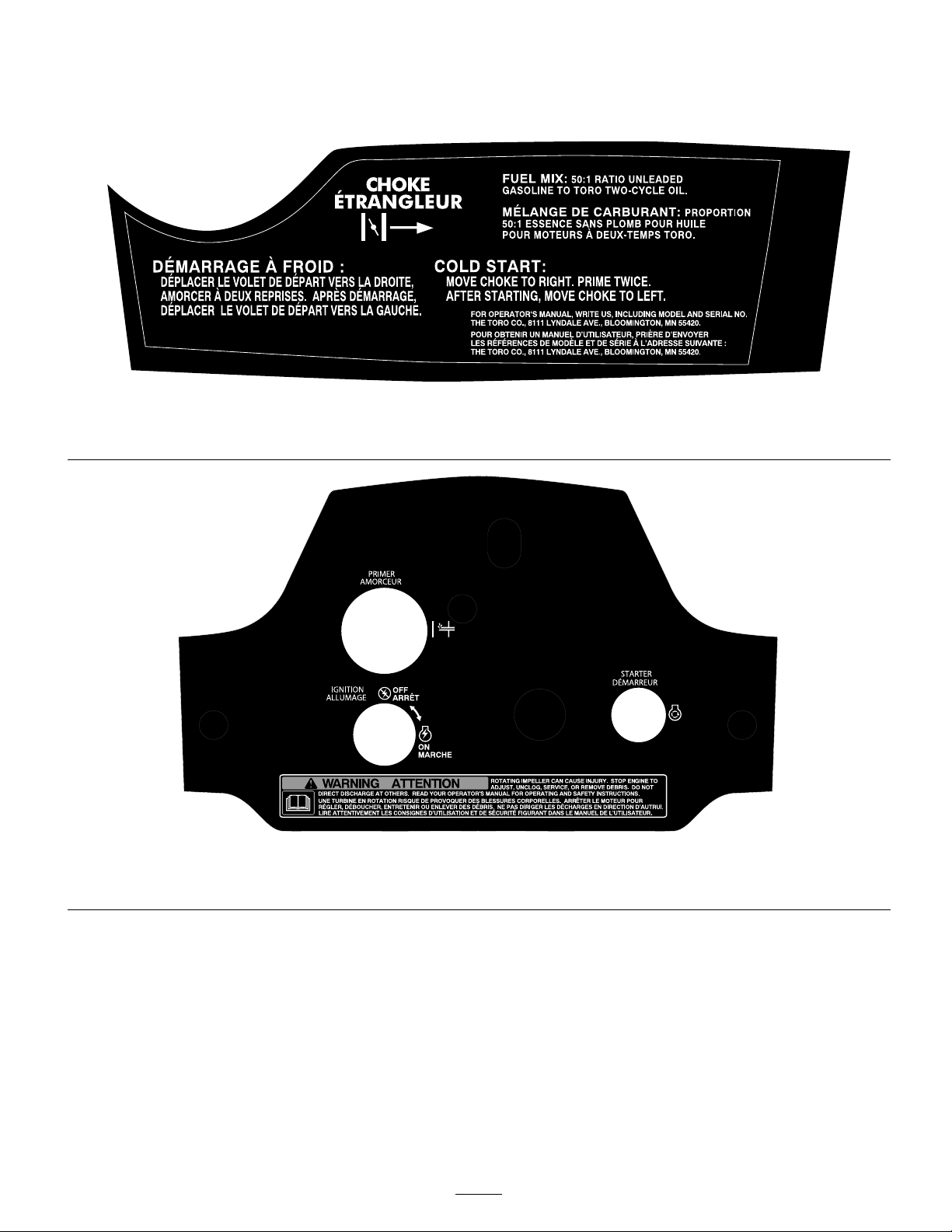
Safety and Instructional Decals
Important: Safety and instr uction decals ar e located near ar eas of potential danger . R eplace dama ged decals.
105-1978
Reorder part no. 108-7335
Reorder part no. 105-1955
105-1981
4
Page 5
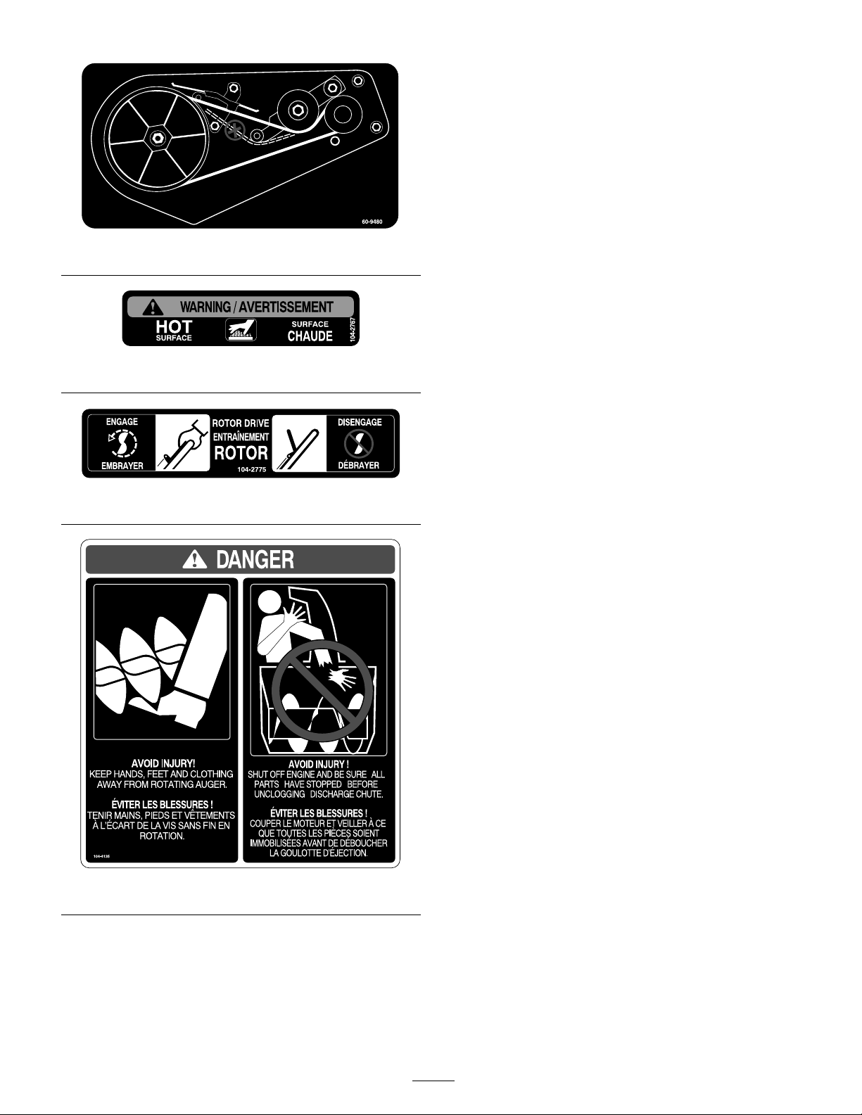
60-9480
104-2767
104-2775
104-4135
5
Page 6
Setup
Loose Parts
Use the chart below to verify that all parts have been shipped.
Step
Handle bolt
1.
2.
3.
Curved washer
Knob
Discharge chute
Phillips head screws
Washers
Locknuts
Chute crank and mounting plate
Bolts
Locknuts
Description
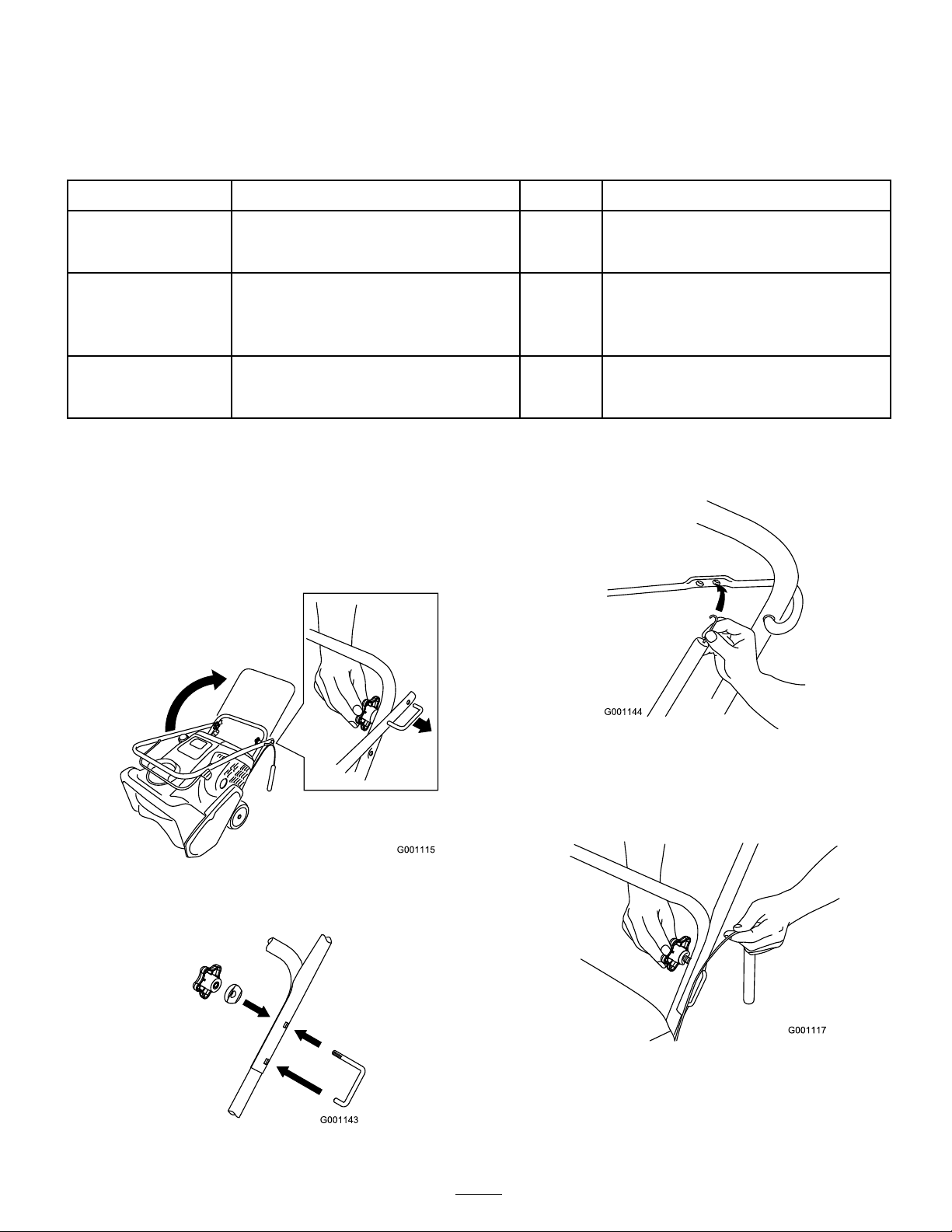
1. Installing the Handle
1. Cut the plastic tie that secures the control cable to the
handle .
Note: Hold the cable taut to ensure that it sta ys
connected at the bottom.
2. P osition the upper handle as sho wn ( Figure 3 ).
Qty.
1
1
1
1
3
3
3
1
2
2
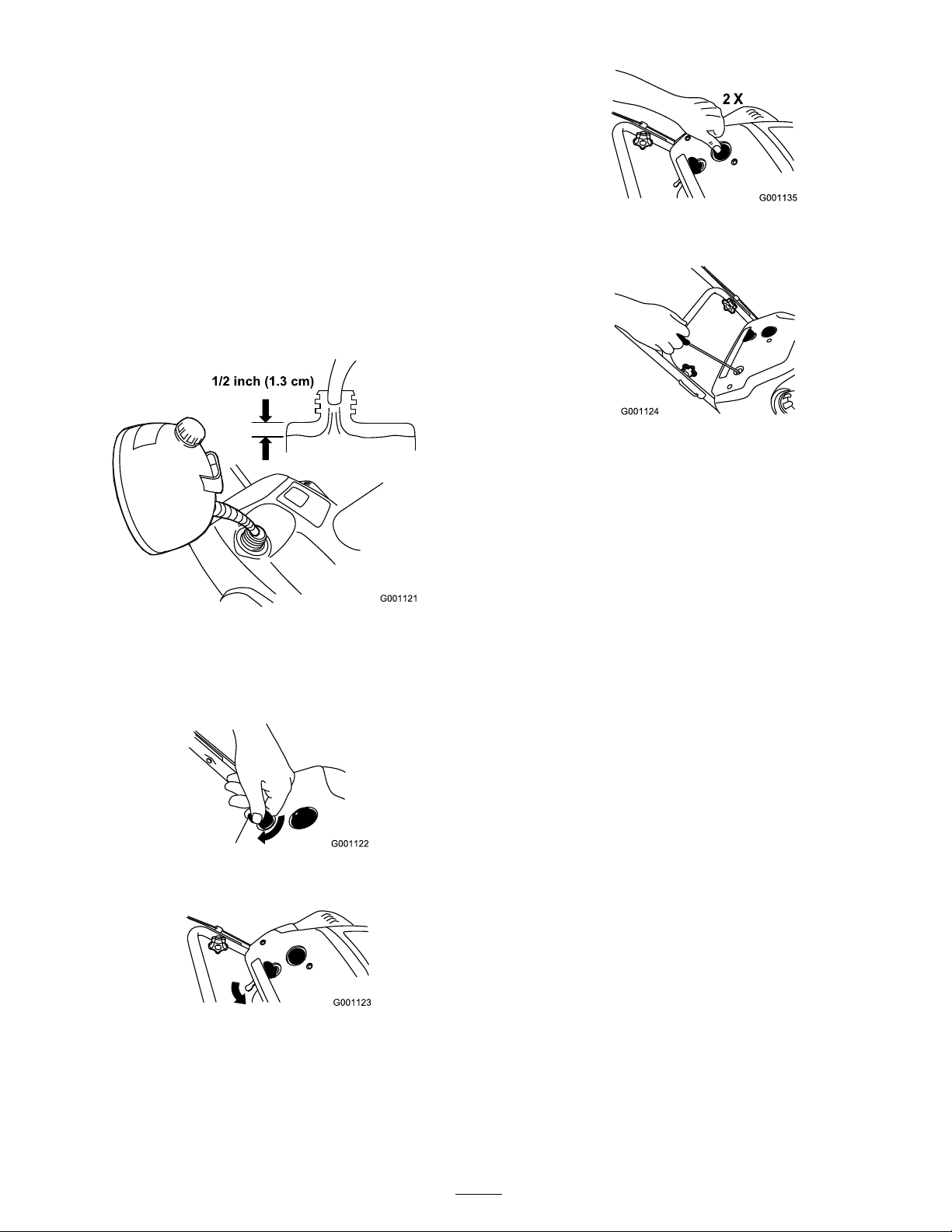
4. Hook the end of the control cable spring into the
bottom hole of the control bar ( Figure 5 ).
Install the handle.
Install the discharge chute.
Install the chute crank.
Use
Figure 3
3. Loosely install the handle bolts , cur v ed w ashers , and
knobs ( Figure 4 ).
Figure 4
Figure 5
5. Fully inser t the handle bolts ( Figure 6 ).
Important: Ensur e that y ou do not pinch the
contr ol ca ble ( Figur e 6 ).
Figure 6
6. Tighten the knobs until they are sn ug .
7. Adjust the control cable . R efer to Adjusting the Control
Cable .
6
Page 7

2. Installing the Discharge
3. Installing the Chute Crank
Chute
Install the disc harg e c hute as sho wn ( Figure 7 ).
Figure 7
1. Inser t the end of the c hute crank through the hole in
the shroud and align the mounting brac k et with the
holes in the lo w er handle ( Figure 8 ).
Figure 8
1. Chute crank 3. Mounting bracket
2. Hole in the shroud 4. Plastic bushing
2. Slo wly rotate the crank until the end of the c hute crank
fits into the hidden g ear opening and the disc harg e
c hute tur ns the crank.
Note: Ensure that the plastic bushing is fully inser ted
into the hole in the mounting brac k et ( Figure 8 ).
3. Secure the mounting brac k et to the handle with 2 bolts
and 2 loc kn uts .
7
Page 8

Product Overview
Operation
Note: Deter mine the left and right sides of the mac hine
from the nor mal operating position.
Gasoline is extr emel y flamma ble and explosi v e. A
fir e or explosion fr om gasoline can bur n y ou and
other s.
• T o pr ev ent a static charge fr om igniting the
gasoline, place the container and/or sno wthr o w er
on the g r ound bef or e filling , not in a v ehicle or
on an object.
Figure 9
1. Discharge chute 6. Knob
2. Chute crank
3. Control bar 8. Rotor blades
4. Handle 9. Fuel tank cap
5. Control panel
Figure 10
1. Key switch 3. Recoil start
2. Primer
7. Handle bolt (2)
4. Choke lever
• Fill the tank outdoor s when the engine is cold.
W ipe up spills.
• Do not handle gasoline when smoking or ar ound
an open flame or spar ks.
• Stor e gasoline in an appr o v ed fuel container , out
of the r each of childr en.
Mixing the Gasoline and Oil
T his sno wthro w er uses a 50:1 g asoline-to-oil mixture . Use
T or o 50:1 2-Cy cle Oil (Fuel Sta biliz er Added) or an
equi v alent high-g rade , NMMA TCW -cer tified tw o-cycle oil.
Important: T o pr ev ent engine dama ge, do not use
automoti v e oil (such as SAE 30 or 10W30) or fuel mix ed
at the wr ong gasoline-to-oil ratio.
1. P our a half US g allon (1.9 liters) of fresh, unleaded
g asoline into an appro v ed fuel container .
2. Add tw o-cycle oil to the g asoline according to the c har t
belo w ( Figure 11 ):
Figure 11
50:1 Gasoline-to-Oil Ratio Mixing Chart
Gasoline Oil
1 US gallon (3.8 liters) 2.6 ounces (80 ml)
2 US gallons (7.6 liters) 5.2 ounces (160 ml)
3. Install the cap on the fuel container .
8
Page 9
4. Shak e the container to mix the g asoline and oil
thoroughly .
5. Slo wly remo v e the cap and add the remaining amount
of g asoline .
Note: Do not mix g asoline and oil in the fuel tank. Oil
at room temperature mix es easier and more thoroughly
than cold oil. Oil belo w 32°F (0°C) requires additional
mixing
Filling the Fuel Tank
Fill the fuel tank with a fresh mixture of g asoline and oil
mix ed at the proper ratio ( Figure 12 ).
Figure 15
4. Pull the recoil star ter ( Figure 16 ).
Figure 16
5. With the engine r unning, mo v e the c hok e lev er to the
left slo wly .
Figure 12
Starting the Engine
1. T ur n the ignition k ey cloc kwise to the On position
( Figure 13 ).
Figure 13
2. Mo v e the c hok e lev er to the right ( Figure 14 ).
Figure 14
3. Fir mly push in the primer 2 times with y our thumb ,
holding the primer in for a second before releasing it
eac h time ( Figure 15 ).
9
Page 10

Stopping the Engine
Adjusting the Discharge Chute
T o stop the engine , tur n the ignition k ey countercloc kwise
to the Off position ( Figure 17 ).
Figure 17
Starting the Rotor Blades
T o star t the rotor blades , hold the control bar ag ainst the
handle ( Figure 18 ).
Figure 18
Stopping the Rotor Blades
T o stop the rotor blades , release the control bar ( Figure 19 ).
T o adjust the disc harg e c hute , rotate the c hute crank and
mo v e the c hute deflector handle as sho wn ( Figure 20 ).
Figure 20
1. Chute handle 2. Chute deector handle
Preventing Freeze-up after Use
• Let the engine r un for a few min utes to prev ent mo ving
par ts from freezing . Stop the engine , w ait for all
mo ving par ts to stop , and remo v e ice and sno w from
the sno wthro w er .
• With the engine off , pull the recoil star ter handle
sev eral times and push the electric star t button once
(if applicable) to prev ent the recoil and electric star ters
from freezing up .
Figure 19
Operating Tips
T he r otor blades can thr o w stones, toys, and other
f or eign objects and cause serious per sonal injur y to
the operator or to bystander s.
• K eep the ar ea to be clear ed fr ee of all objects that
the r otor blades could pick up and thr o w .
• K eep all childr en and pets a w ay fr om the ar ea
of operation.
• R emo v e the sno w as soon as possible after it falls .
• T o self-propel, raise the handle and tilt the sno wthro w er
slightly forw ard, lifting the wheels off the g round.
T he more y ou tilt the handle forw ard, the faster the
sno wthro w er self-propels .
• If the sno wthro w er does not propel itself forw ard on
slipper y surfaces or in hea vy sno w , push forw ard on
the handle , but allo w the sno wthro w er to w ork at its
o wn pace .
10
Page 11

• Ov erlap eac h sw ath to ensure complete sno w remo v al.
• Disc harg e the sno w do wnwind whenev er possible .
• In sno wy and cold conditions , some controls and
mo ving par ts ma y freeze . Do not use ex cessi v e force
when tr ying to operate frozen controls . If y ou ha v e
difficulty operating any control or par t, star t the engine
and let it r un for a few min utes .
Maintenance
Note: Deter mine the left and right sides of the mac hine from the nor mal operating position.
Recommended Maintenance Schedule(s)
Maintenance Service
Interval
After the rst operating
hour
Yearly
Yearly or before storage
Maintenance Procedure
• Check the control cable both initially and after the rst hour of operation; adjust it
if necessary.
• Check for loose fasteners and tighten them if necessary.
• Check the control cable and adjust it if necessary.
• Check for loose fasteners and tighten them if necessary.
• Have an Authorized Service Dealer inspect the spark plug and replace it if
necessary.
• Inspect the rotor blades and have an Authorized Service Dealer replace the rotor
blades and scraper if necessary.
• Have an Authorized Service Dealer inspect the drive belt and replace it if necessary.
• Prepare the snowthrower for storage.
Adjusting the Control Cable
Checking the Cable
Important: Check the contr ol ca ble f or pr oper
adjustment initiall y , after the fir st operating hour , and
then ann uall y ther eafter .
1. Mo v e the control bar bac k to w ard the handle to remo v e
the slac k in the cable .
2. Ensure that a 1/16 to 1/8 inc h (2 to 3 mm) g ap exists
betw een the control bar and the handle ( Figure 21 ).
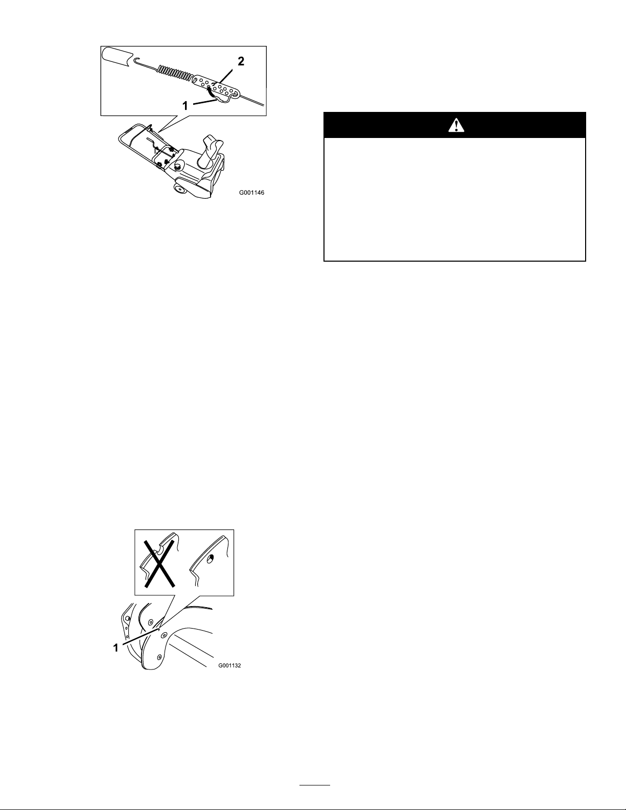
Adjusting the Cable
1. Unhook the end of the control cable spring from the
control bar ( Figure 22 ).
Figure 21
1. 1/16 to 1/8 inch (2 to 3 mm) gap
Note: T o adjust the cable , refer to Adjusting the Cable
belo w .
Important: T he contr ol ca ble must contain some
slack when y ou disenga ge the contr ol bar f or the
r otor blades to stop pr oper l y .
Figure 22
2. Mo v e the Z-fitting to a higher or lo w er hole in the
adjuster link as needed to obtain the 1/16 to 1/8 inc h
(2 to 3 mm) g ap betw een the control bar and the handle
( Figure 23 ).
11
Page 12
Storage
Storing the Snowthrower
• Gasoline fumes ar e highl y flamma ble, explosi v e,
and danger ous if inhaled. If y ou stor e the pr oduct
in an ar ea with an open flame, the gasoline fumes
may ignite and cause an explosion.
Figure 23
1. Z-tting 2. Adjuster link
Note: Mo ving the Z-fitting higher decreases the g ap
betw een the control bar and the handle; mo ving it lo w er
increases the g ap .
3. R e place the spring co v er and hook the end of the
control cable spring into the bottom hole of the control
bar .
4. Chec k the adjustment; refer to Chec king the Cable .
Note: After extended use , the dri v e belt ma y w ear and lose
its proper belt tension. If the dri v e belt slips (contin uously
squeals) under a hea vy load, increase the belt tension b y
inser ting the spring end into the top hole of the control
bar . T he belt ma y slip (squeal) in w et conditions; to dr y out
the dri v e system, star t the rotor and r un it without a load
for 30 seconds .
Inspecting the Rotor Blades
Before eac h season, inspect the rotor blades for w ear . W hen
a rotor blade edg e has w or n do wn to the w ear indicator
hole , ha v e an A uthorized Ser vice Dealer re place the rotor
blades and the scraper ( Figure 24 )
• Do not stor e the sno wthr o w er in a house (li ving
ar ea), basement, or an y other ar ea wher e ignition
sources may be pr esent, such as hot w ater and
space heater s, clothes dr y er s, fur naces, and other
lik e appliances.
Important: Do not use the chute handle to lift the
sno wthr o w er . T his can dama ge the chute handle.
1. Add a fuel stabilizer/conditioner to the fuel in the fuel
tank as directed.
Note: If y ou use T oro 50:1 2-Cycle Oil (Fuel
Stabilizer Added) , y ou do not need to add a fuel
stabilizer/conditioner .
2. R un the engine for 5 min utes to distribute the
conditioned fuel through the fuel system.
3. Stop the engine and allo w it to cool.
4. Use a hand pump to pump the fuel from the fuel tank
into an appro v ed fuel container , or r un the engine until
it stops .
5. Star t the engine and r un it until it stops .
6. Chok e or prime the engine , star t it a third time , and r un
the engine until it will not star t.
7. Slo wly pull the recoil star ter until y ou feel resistance due
to compression pressure , then stop .
Figure 24
1. Wear indicator hole
8. R elease the star ter tension g radually b y allo wing the
rope to g o bac k slo wly to prev ent the engine from
rev ersing due to compression pressure .
9. Dispose of un used fuel properly . R ecycle it according to
local codes , or use it in y our automobile .
Note: Do not store stabilized fuel for more than 90
da ys .
10. Tighten all loose screws , bolts , and loc kn uts . R e pair or
re place any damag ed par ts .
11. Clean the sno wthro w er thoroughly .
12. Co v er the sno wthro w er and store it in a clean, dr y place
out of the reac h of c hildren. Allo w the engine to cool
before storing it in any enclosure .
12
Page 13
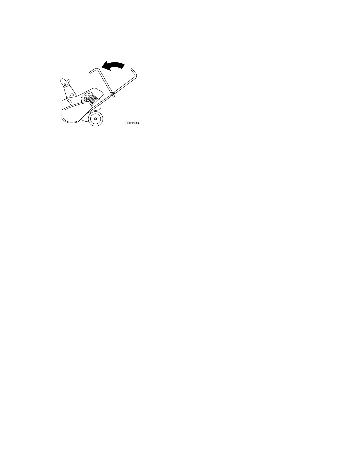
Folding the Handle
1. Loosen the knobs and pull out the handle bolts .
2. F old the upper handle forw ard ( Figure 25 ).
Figure 25
13
Page 14

Page 15

Page 16

Snow Commander
and
Power Curve
Single-stage
Snow Products
The Toro 5-Year GTS Starting Guarantee and
The Toro 2-Year Total Coverage Guarantee
A Full Warranty (Limited Warranty for Commercial Use)
Conditions and Products Covered under The Toro Starting Guarantee
The Toro Company and its afliate, Toro Warranty Company, guarantee that your Toro GTS (Guaranteed to Start) engine, when used for residential purposes*,
will start on the rst or second pull for ve (5) years from the date of purchase, if you provide the routine maintenance it requires, or we will x it free of charge.
This warranty covers the cost of parts and labor, but you must pay transportation costs. This warranty applies to all Snow Commander® and Power Curve®
single-stage Toro Snowthrowers. (Not Powerlite® models.)
Conditions and Products Covered under The Toro Total Coverage Guarantee
The Toro Company and its afliate, Toro Warranty Company, promise to repair any Toro Product used for residential purposes* if defective in materials or
workmanship or if it stops functioning due to the failure of a component for a period of two (2) years from the date of purchase.
This warranty covers the cost of parts and labor, but you must pay transportation costs. This warranty applies to all Snow Commander® and Power Curve®
single-stage Toro Snowthrowers. (Not Powerlite® models.)
Limited Warranty for Commercial Use
Gas-powered Toro Snowthrowers used for commercial, institutional, or rental use are warranted for 45 days against defects in materials or workmanship.
Components failing due to normal wear are not covered by this warranty. The Toro Starting Guarantee does not apply when the product is used commercially.
Items and Conditions Not Covered
There is no other express warranty. This express warranty does not cover the following:
• Cost of regular maintenance service or parts, such as lters, fuel, lubricants, oil changes, spark plugs, cable/linkage adjustments, or brake and clutch
adjustments
• Any product or part which has been altered or misused or required replacement or repair due to accidents or lack of proper maintenance
• Repairs necessary due to electrical supply irregularities or failure to properly prepare the snowthrower prior to any period of non-use over three months
• Pickup and delivery charges
• Operational misuse, neglect, or accidents
• Repairs or attempted repairs by anyone other than a Toro Service outlet
• Repairs or adjustments to correct starting difculties due to the following:
– failure to follow proper maintenance procedures
– snowthrower auger/paddles striking an object
– contaminants in the fuel system
– improper fuel or fuel/oil mixture (consult your Operator’s Manual if in doubt)
– failure to drain the fuel system prior to any period of non-use over three months
• Special operational conditions where starting may require more than two pulls:
– rst time starts after extended period of non-use over three months or seasonal storage
– improper starting procedures
If you are having difculty starting your unit, please check the Operator’s Manual to ensure that you are using the correct starting procedures. This can
save an unnecessary visit to a Service Dealer.
Owner Responsibilities
You must maintain your Toro Product by following the maintenance procedures described in the Operator’s Manual . Such routine maintenance, whether
performed by a dealer or by you, is at your expense.
Instructions for Obtaining Warranty Service
If you think that your Toro Product contains a defect in materials or workmanship, or if a normal, able-bodied adult can no longer start your product’s engine
in one or two pulls, follow this procedure:
1. Contact any Toro Authorized or Master Service Dealer to arrange service at their dealership. To locate a dealer convenient to you, refer to the Yellow Pages of
your telephone directory (look under Lawn Mowers ) or access our website at www.Toro.com. You may also call our Toro Customer Care Department toll free
at 866-336-5205 (U.S. customers) or 866-854-9033 (Canadian customers).
2. Bring the product and your proof of purchase (sales receipt) to the Service Dealer.
3. If for any reason you are dissatised with the Service Dealer’s analysis or with the assistance provided, contact us at: Customer Care Department, Consumer
Division, Toro Warranty Company, 8111 Lyndale Avenue South, Bloomington, MN 55420-1196.
General Conditions
All repairs covered by these warranties must be performed by an Authorized or Master Toro Service Dealer using Toro approved replacement parts. Repair by a
Toro Service Dealer is your sole remedy under these warranties.
Neither The Toro Company nor Toro Warranty Company is liable for indirect, incidental, or consequential damages in connection with the
use of the Toro Products covered by these warranties, including any cost or expense of providing substitute equipment or service during
reasonable periods of malfunction or non-use pending completion of repairs under these warranties.
Some states do not allow exclusions of incidental or consequential damages, or limitations on how long an implied warranty lasts, so the
above exclusions and limitations may not apply to you. This warranty gives you specic legal rights, and you may also have other rights
which vary from state to state.
Countries Other than the United States or Canada
Customers who have purchased Toro products exported from the United States or Canada should contact their Toro Distributor (Dealer) to obtain guarantee
policies for your country, province, or state. If for any reason you are dissatised with your Distributor’s service or have difculty obtaining guarantee information,
contact the Toro importer. If all other remedies fail, you may contact us at Toro Warranty Company.
* Residential purposes means use of the product on the same lot as your home. Use at more than one location is considered commercial use, and the commercial
use warranty would apply.
374-0059 Rev A
 Loading...