

Page 1

Product Data Sheet
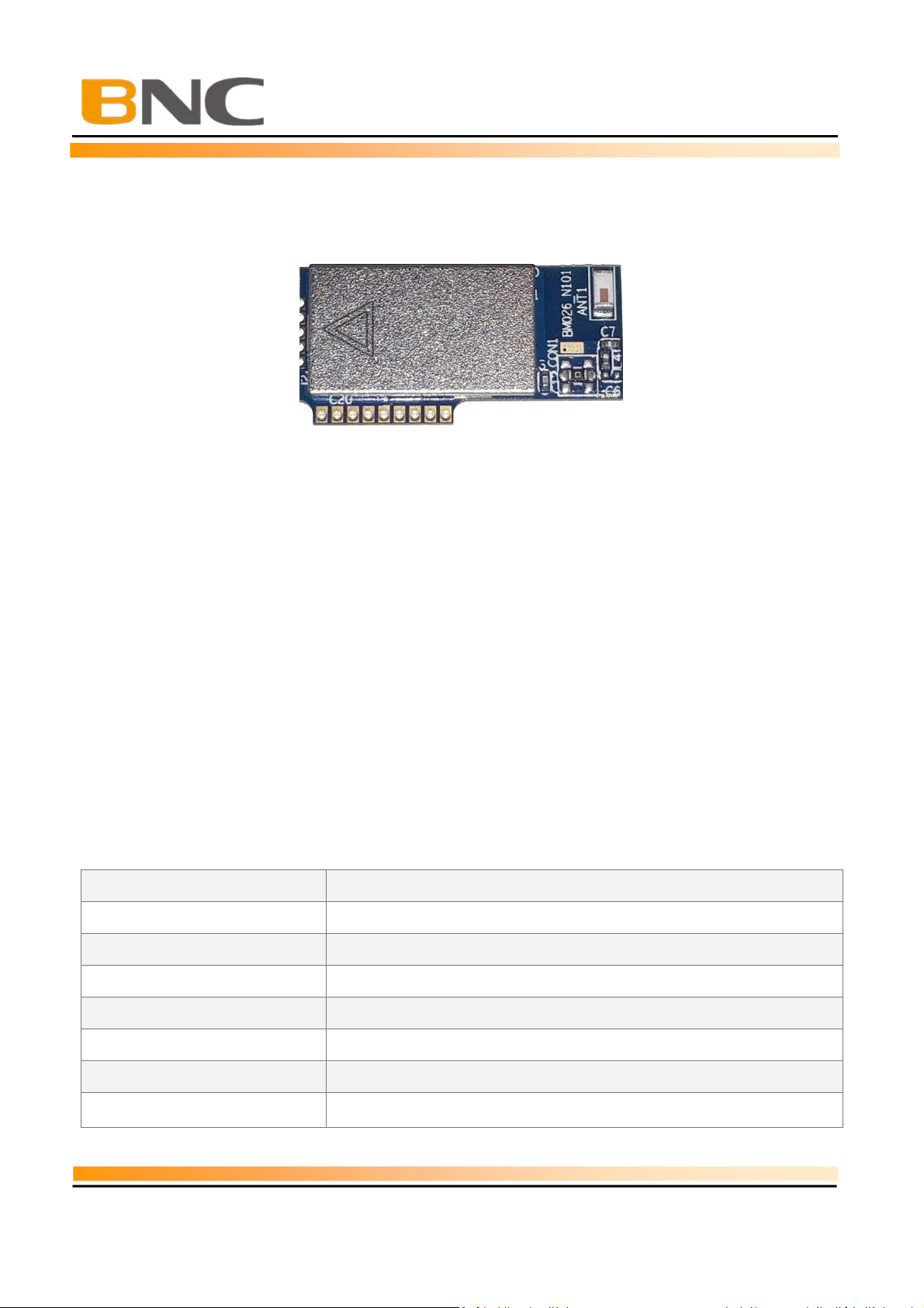
BM026
BM026
Bluetooth Low Energy Module
Datasheet
Version 1.3
Issued date: Aug 21, 2019
BLTC Network Corp
9F., No.127-2, Anxing Rd., Xindian Dist., New Taipei City, Taiwan
Phone : +886286663611
Mail :
sales@bltcnetwork.com.tw
- 1 -
Page 2

Product Data Sheet
Version : 1.1
- 2 -
10/08/2018
BM026
TABLE OF CONTENTS
Revision History ................................................................................. 4
1.
2.
3.
4.
6.
BNC BLE Module ........................................................................ 5
1.1 Introduction ..................................................................................... 5
1.2 Feature ................................................................................................ 5
Ordering Information .................................................................. 7
Pin Configurations ...................................................................... 8
3.1 Pin Assignments ............................................................................... 8
3.2 Pin Description ................................................................................. 9
Outline Drawing ........................................................................ 11
4.1 Board Dimensions (Unit: mm) ........................................................ 11
5. Host PCB Footprint (Unit: mm) ....................................................... 11
Electrical Characteristics ......................................................... 12
7.
8.
9.
Recommended Temperature Reflow Profile .......................... 13
7.1 Hand Soldering ............................................................................... 13
7.2 Rework ........................................................................................... 13
7.3 Cleaning ......................................................................................... 14
Application Notes ..................................................................... 15
8.1 Flash Use ........................................................................................ 15
8.2 Mounting ....................................................................................... 15
Compliance information ........................................................... 16
Page 3

Product Data Sheet
Version : 1.1
- 3 -
10/08/2018
BM026
9.1
Federal Communications Commission (FCC) Statement ..... 16
Page 4

Version : 1.1
- 4 -
10/08/2018
Product Data Sheet
BM026
Revision History
Revision Date Description
V1.0 2018/07/01 Initial release
V1.1 2018/10/08 Added ADC PIN
V1.2 2019/03/16 Modify spec
V1.3 2019/08/21
Added Certification information
Page 5
Version : 1.1
- 5 -
10/08/2018
Product Data Sheet
1. BNC BLE Module
BM026
1.1 Introduction
BM026
BM026 Bluetooth® module is a Telink’s 32Bit MCU SoC Bluetooth low energy products for
the Bluetooth Smart market. BM026 increases application code and data space for greater
application development flexibility. It is slim and light so the designers can have better
flexibilities for the product shapes.
The BM026 Bluetooth module compatible with Bluetooth standard and supports BLE
specification up to version 4.2.It supports profiles for health and fitness sensors, watches,
i-Beacon, It’s Also support BLE Mesh protocol for Smart Lighting ,Mesh Gateway ,IoT system
leave network topology application . It integrates BLE/15.4 2.4G RF Baseband controller,
antenna, The BM026P PA Version It integrates a high-efficiency PA IC ,It with 7dBm RF
Output Power for Long-distance applications. And it also provides UART /i2C/SPI interface,
programmable I/O,ADC etc.
1.2 Feature
Specification
Module Name BM026
Chips ID TLSR8269 F512ET32
Wireless Protocol BLE up to version 4.2
Transceiver Type 1TX x 1RX
Data Rate
Operating Frequency 2402MHz~2480MHz
Antenna Onboard Chips Antenna
Transmission Range >70M (open side)
1 Mbps and 2 Mbps LE Enhancement FIPD Version
Page 6
Version : 1.1
- 6 -
10/08/2018
Product Data Sheet
RF Output Power +7 dBm,
Power Consumption TX: 30~35mA / RX: 20
BM026
Interface Port
Processor Embedded 32 Bit MCU with clock Up to 48Mhz
Memory Build-in 512KB Program Flash ,16KB SRAM
Security Hardware AES-128 Encryption
Firmware Upgrade OTA (Over the Air) or SWS wire Port
Power Supply DC 1.9V~3.6V
Operating Environment -40 ~ +85°C(
Dimensions 27(L) x 13.5(W) x 2.5(H) mm(PCB 1.0mm)
Environmental standard RoHS-compliant and 100% lead (Pb)-free.
USB ,5 x PWM ,or 1 x I2C,1 x UART,5x GPIO, total 7 GPIOs
for Option Pin define
VT to
+125°C) , 0~95% RH
Page 7

Version : 1.1
- 7 -
10/08/2018
Product Data Sheet
2. Ordering Information
BM026XXX-X S S
Software Ttpe:
Hardware Type:
E = External RF Pin out Version
C = Onboard Chips Antenna Version
BM026
P9E = TLSR8269 Topr -40~85°C With PA Versions
P9V = TLSR8269 Topr -40~125°C With PA Versions
N9E = TLSR8269 Topr -40~85°C Versions
N9V = TLSR8269 Topr -40~125°C Versions
Page 8

Version : 1.1
- 8 -
10/08/2018
Product Data Sheet
3. Pin Configurations
3.1 Pin Assignments
BM026
BM026 Pin -Out
Page 9

Version : 1.1
- 9 -
10/08/2018
Product Data Sheet
Application
Type Code
3.2 Pin Description
P1 Pin Define
Pin No Pin name Type Description
BM026
1
3.3V
2
GND GND Ground
3 PWM3/C3 I/O
4 PWM2/C2 I/O
5 PWM1/A3 I/O
6 PWM5/B6 I/O
7 PWM4/B4 I/O
8 ADC1/B1 I/O
9 ADC2/B5 I/O
Power
PA Version Control Pin Define
Pin No Pin name Type Description
1
TX_EN/D2
2
RX_EN/C5 O PA IC RX Enable, GPIO_PC5
O
Mesh Lighting Application Table
Pin
Product type Single
1
3.3V
2
GND
3
PWM3/C3 Lum WW
4
PWM2/C2
5
PWM1/A3
6
PWM5/B6
7
PWM4/B4
ADC1/B1
8
ADC2/B5
9
3.3V 3.3V 3.3V 3.3V 3.3V
GND GND GND GND GND
On/Off
Rly hi Act
On/Off
DI_Lo Act
i-Detc i-Detc i-Detc i-Detc i-Detc
V-Detc V-Detc V-Detc V-Detc V-Detc
CW/WW
01 02 03 04 05
CW
Power Source
PWM3,GPIO_PC3,UART_RX
PWM2,GPIO_PC2,UART_TX
PWM1,GPIO_PA3(PB7), I2C_SCK(by soft)
PWM5,GPIO_PB6, I2C_SDA(by soft)
PWM4,GPIO_PB4
ADC1,GPIO_PB1
ADC1,GPIO_PB5
PA IC TX Enable, GPIO_PD2
LED Lighting
RGB/
RGB RGBW
R
WW WW
R
G G G
B B B
WW_CW
CW
R
P2 Pin Define
Pin No Pin name Type Description
1
3.3V
Power
Power Source
Page 10

Product Data Sheet
Version : 1.1
- 10 -
10/08/2018
BM026
2
SWS
I/O
GPIO_PB0,PWM2,Single Wire Slave
3
4 DM I/O
5 DP I/O
GND GND Ground
GPIO_PE2,USB Date Minus
GPIO_PE3,USB Date Positive
Page 11

Product Data Sheet
Version : 1.1
- 11 -
10/08/2018
4. Outline Drawing
4.1 Board Dimensions (Unit: mm)
BM026
Note:
*The P1 Slot All of Pin have 0.65mm hole design, It can use 1x9 1.27mm pith pin
header parts to connection host board
5. Host PCB Footprint (Unit: mm)
Note:
*When Use the BM026 Module to design product. Please Layout BM026 in the
upper right corner of the Host PCB, So as to ensure a good antenna efficiency.
*Demarcation specifies the “Host PCB copper keep-out area”
*The 6.5mm x 6.5mm area specifies copper keep-out component layer
Page 12

Product Data Sheet
Version : 1.1
- 12 -
10/08/2018
6. Electrical Characteristics
Absolute Maximum Ratings :
Symbol Parameters Maximum rating Unit
VDD Power Supply Voltage -0.3 to 3.9 V
Tstr Storage Temperature -65 to +150 °C
BM026
Tsld
VESD ESD protection (HBM) 2000 V
Soldering Temperature 260 °C
Operating Conditions
Supply Voltage VDD
I/O Supply Voltage
Temperature Range (ET Versions)
Temperature Range (VT Versions)
DC Electrical Characteristics
V
IL
Input Voltage Low VSS 0.3VDD V
V
IH
Input Voltage High 0.7VDD VDD V
V
OL
Output Voltage Low, (IO is 4~16mA) VSS 0.3 V
V
OH
Output Voltage High, (IO is 4~16mA) VDD VDD-0.3 V
Min. Typ. Max. Unit
1.9
3.3 3.6 V
-40
-40
3.3+/-10%
-
85
-
105
Min. Max. Unit
º
º
V
C
C
USB Electrical Characteristics
USB Output Signal Cross-over Voltage Vcrs 1.7 2.0 V
Current Consumption
(VDD = 3.3V, TA = 25°C, unless otherwise specified)
TX Current (Continuous Tx 0dbm )
RX Current (Continuous Rx Reception)
TX Current (with PA Tx 7dbm )
RX Current (With PA Rx Reception)
Suspend Mode Current
Min. Max. Unit
Min. Avg. Max. Unit
15
12
180~210
30
0.6
mA
mA
mA
mA
mA
Page 13

Product Data Sheet
Version : 1.1
- 13 -
10/08/2018
7. Recommended Temperature Reflow Profile
BM026
Maximum number of reflow cycles: 2
Opposite side reflow is prohibited due to the module’s weight. (i.e. you must not place the
module on the
bottom / underside of your PCB and reflow).
7.1 Hand Soldering
Hand soldering is possible. When using a soldering iron, follow IPC recommendations
(reference document IPC-7711).
7.2 Rework
Page 14

Version : 1.1
- 14 -
10/08/2018
Product Data Sheet
BM026
The module can be unsoldered from the host board. Use of a hot air rework tool should be
programmable and the solder joint and module should not exceed the maximum peak reflow
temperature of 250°C.
If temperature ramps exceed the reflow temperature profile, module and component
damage may occur due to thermal shock. Avoid overheating. Never attempt a rework on the
module itself, (e.g. replacing individual components).
7.3 Cleaning
In general, cleaning the populated modules is strongly discouraged. Residuals under the
module cannot be easily removed with any cleaning process. Use of “No Clean” soldering
paste is strongly recommended, as it does not require cleaning after the soldering process.
Page 15

Version : 1.1
- 15 -
10/08/2018
Product Data Sheet
BM026
8. Application Notes
8.1 Flash Use
The BM026 Module has been calibrated by RF before leaving the factory , That has
various ID and parameter information of the BM026 module need to be retained, Please
don’t use the “EraseF” button to erase the All Flash of the BM025 module
8.2 Mounting
BM026 has two sets of soldering pads, which allow it to be mounted both in horizontal
and vertical position. In some application, such as LED drivers, there are large
components which could affect the antenna performance greatly if the module is
mounted at the bottom of the device horizontally on the main PCB. Also, horizontally
mounted module has much larger footprint compared to vertically mounted module.
For such cases the module can be mounted in vertical position, either by soldering it to a
1x9 1.27 mm pitch 1-row pin header, or by soldering the module directly into a routed
slot on the main PCB.
When mounted in horizontal position there will have to be two keep-out areas; one for
the antenna area and one for the unused pads used for vertical assembly.
Page 16

Version : 1.1
- 16 -
10/08/2018
Product Data Sheet
9. Compliance information
Compliance Information
Radio USA FCC Part 15 Subpart C
BM026
FCC ID (BM026):
IC ID
Bluetooth (BQB) Bluetooth Product Listing
Declaration ID (DID) Not Ready
Model Number: BM026P9E-C SS
Environmental RoHS RoHS compilant
REACH REACH compilant
OF7-BTM002
3575A-BTM002
BM026P9V-C SS
9.1 Federal Communications Commission (FCC) Statement
Compliance Statement
This device complies with part 15 of the FCC Rules. Operation is subject to the following two
conditions:
(1)
This device may not cause harmful interference, and
(2)
this device must accept any interference received, including interference that may
cause undesired operation.
Warning
Any Changes or modifications not expressly approved by Toro Company could void the
user’s authority to operate the equipment.
Page 17

Version : 1.1
- 17 -
10/08/2018
Product Data Sheet
BM026
FCC Interference Statement
This equipment has been tested and found to comply with the limits for a Class B digital
device, pursuant to
Part 15 of the FCC Rules. These limits are designed to provide reasonable protection
against harmful interfer-ence in a residential installation.
This equipment generates, uses and can radiate radio frequency energy and, if not installed
and used in accordance with the instructions, may cause harmful interference to radio
communications.
However, there is no guarantee that interference will not occur in a particular installation. If
this equipment does cause harmful interference to radio or television reception, which can
be determined by turning the equipment off and on, the user is encouraged to try to correct
the interference by one of the following meas- ures:
•
Reorient or relocate the receiving antenna.
•
Increase the separation between the equipment and receiver.
•
Connect the equipment into an outlet on a circuit different from that to which the
receiver is connected.
•
Consult the dealer or an experienced radio/TV technician for help.
It is the host manufacturer’s responsibility to ensure continued compliance with FCC
requirements once the module has been installed in to the host product.
This transmitter must not be co-located or operating in conjunction with any other
antenna or transmitter.
Radiation Exposure Statement:
This equipment complies with FCC radiation exposure limits set forth for an uncontrolled
environment. This equipment should be installed and operated with minimum distance 20cm
between the radiator & your body.
Page 18

Version : 1.1
- 18 -
10/08/2018
Product Data Sheet
BM026
This device is intended only for OEM integrators under the
following conditions:
In accordance with FCC Part 15C and RSS-210, this module is listed as a Modular
Transmitter device.
Changes or modifications not expressly approved by the manufacturer could void the user’s
authority to operate the equipment.
The antenna of this transmitter must not be co-located or operating in conjunction with any
other antenna or transmitters within a host device, except in accordance with FCC
multitransmitter product approval procedures.
End Product Labeling
The outside of final products that contains this module device must display a label
referring to the enclosed module. This exterior label can use wording such as the
following: “Contains Transmitter Module FCC ID: [
[
OF7-BTM002
Additionally, there must be the following sentence on the device, unless it is too small to
carry it:
“This device complies with part 15 of the FCC Rules. Operation is subject to the following
two conditions:
(1)
This device may not cause harmful interference, and
(2)
this device must accept any interference received, including interference that may cause
undesired operation.”
].” Any similar wording that expresses the same meaning may be used.
OF7-BTM002
]” or “Contains FCC ID:
If the final product is to be sold in Canada, then this exterior label should use wording
such as the following: “Contains Transmitter Module IC: [
Manual Information To the End User
The following statements should be inside the user manual of the final products that contains
this module:
3575A-BTM002
]”
Page 19

Version : 1.1
- 19 -
10/08/2018
Product Data Sheet
BM026
Changes or modifications not expressly approved by the party responsible for compliance
could void the user’s authority to operate the equipment.
Canada:
Le présent appareil est conforme aux CNR d'Industrie Canada applicables aux appareils
radio exempts de licence. L'exploitation est autorisée aux deux conditions suivantes : (1)
l'appareil ne doit pas produire de brouillage, et (2) l'utilisateur de l'appareil doit accepter tout
brouillage radioélectrique subi, même si le brouillage est susceptible d'en compromettre le
fonctionnement.
This device complies with Industry Canada license-exempt RSS standard(s). Operation is
subject to the following two conditions: (1) this device may not cause interference, and (2)
this device must accept any interference, including interference that may cause undesired
operation of the device
 Loading...