

Page 1
Micro-Irrigation
1/2"
Vacuum
Breaker
1" & 2"
Continuous
Acting Air
Release
Valves
1"
Plastic
Air Vent
Air/Vacuum Valves
Air and vacuum control is essential to the safety,
longevity, efficiency, and performance of an
irrigation system. Air must be allowed to exit
pipelines 1) upon startup to prevent water
hammer, 2) during normal operation to prevent
the development of air pockets, and 3) air must be
allowed to enter pipelines and laterals at shut down
to prevent vacuum suction. Various types of valves
and vents are available to perform these functions.
Application:
Removal of Air from Pipelines
• Avoid Water Hammer: Air must be allowed
to escape pipelines at the same rate as water
enters the pipeline during system startup to
avoid dangerous water hammer from
occurring.
• Remove entrained or dissolved air:
Air that has accumulated at high points
during system operation must be allowed to
escape to avoid air pockets which restrict the
flow of water and can cause water hammer.
1" & 2"
Air
Release
and
Vacuum
Relief
Valves
2", 3" & 4" Aluminum Air Vents
Allow the Entry of Air into Pipelines
• Prevent Vacuum Suction in Pipelines:
Air must be allowed to re-enter main and
submain pipelines as water drains during
system shut down to prevent negative
suction from occurring and potential
collapse of the pipelines.
• Prevent Vacuum Suction in Laterals:
Laterals which are buried or submerged in
water may ingest dirty water and/or soil
through the emitters as a result of vacuum
suction if air is not allowed to enter the
laterals during system shut-down and
drainage.
Page 2
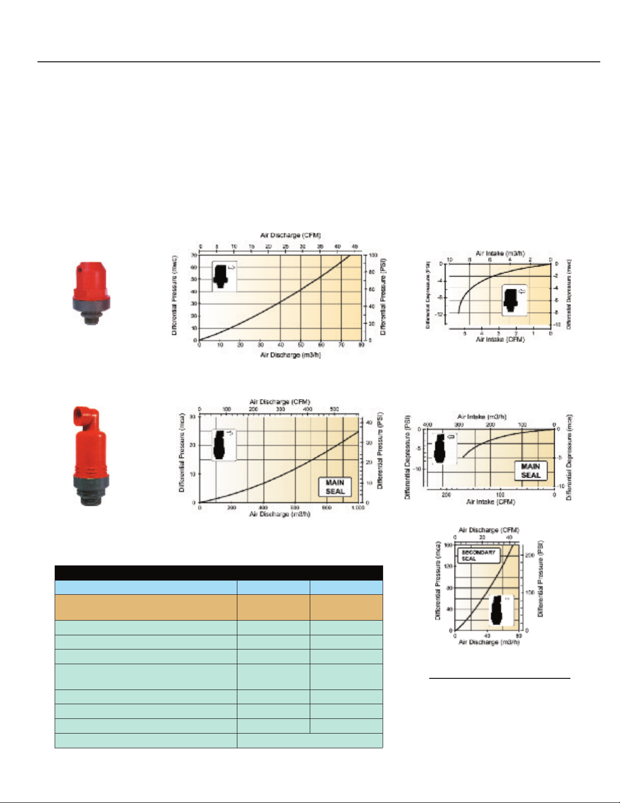
Continuous Acting Air Release Valves
1" & 2" Combination Large Volume Air Relief and Continuous Acting Air Release & Vacuum Relief Valve
• Install at highest points on filter and pump stations to provide both instantaneous and continuous
air relief
• Install on main manifolds every 1000 feet to introduce air into the irrigation system at shutdown to
prevent pipe collapse
• Install at highest point of slope to provide vacuum relief at system shutdown
Model #ARV-1-A
Model #ARV-2-KA
Specifications
Part Number ARV-1-A ARV-2-KA
Valve Type
Connection - male NPT (in) 1 2
Working Pressure (psi) 170 225
Sealing Pressure (psi) 3 3
Volume of air release without valve closing
and without the presence of water (CFM)
Release Air Volume @ 5 psi 8.8 CFM 140 CFM
Units per Box 20 8
Box Weight (lbs) 15 16
Packing Dimensions (in) 15" x 11" x 8"
Single Acting
Continuous
41.2 590
Dual Acting
Continuous
Unit Glossary:
CFM Cubic Feet per Minute
PSI Pounds per Square Inch
m3/h Cubic Meters per Hour
in Inches
1 Cubic Foot of Water = 7.48 Gallons
Page 3

Air Release and Vacuum Relief Valves
1" & 2" Air Release & Vacuum Relief Valves
• Install on manifolds to exhaust air at system start-up
• Install on manifolds to introduce air into the pipeline and provide vacuum relief after system shutdown
• Install downstream of valves to introduce air into the pipeline and provide vacuum relief after
valve shutdown
• Install at highest point of slope to introduce air into the pipeline and provide vacuum relief after
valve shutdown
Model #ARV-1-K
Model #ARV-2-K
Specifications
Part Number ARV-1-K ARV-2-K
Valve Type
Connection - male NPT (in) 1 2
Working Pressure (psi) 225 225
Sealing Pressure (psi) 3 3
Volume of air release without valve closing
and without the presence of water (CFM)
Release Air Volume @ 5 psi 26 CFM 260 CFM
Units Per Box 14 8
Box Weight (lbs) 12 14
Packing Dimensions (in) 15" x 11" x 8"
Air / Vacuum Relief
Non-Continuous
295 590
Page 4

Aluminum Air Vents
Application:
The Aluminum Air Vent series can be
used on gravity or higher pressure
systems, allowing for operation up to 150
psi on the 2" model and 100 psi on 3"
and 4" models. The float and precision ORing provide a tight seal at a very low
pressure, while the strong aluminum alloy
body and full baffle allow for maximum
vent capacity without premature closing.
Air Intake Flow Chart
Hg
Air Discharge Flow Chart
Features and Benefits:
• Cast Aluminum body
combines lightweight strength
and corrosion resistance
• Synthetic rubber O-ring
assures a positive seal even
with low head applications
• Simple design ensures troublefree performance
• Available in 2", 3", & 4"
Female NPT inlet
Specifications
Part Number ARV-2AV ARV-3AV ARV-4AV
Valve Type
Connection - female NPT (in) 2 3 4
Working Pressure (psi) Max. 150 Max. 100 Max. 100
Units per Box 25 10 4
*Conversion: 1 cubic foot of water = 7.48 gallons
Aluminum
Air Vent
Aluminum
Air Vent
Aluminum
Air Vent
Page 5

1/2" Vacuum Breaker
1-3/4" (43 mm)
1
" (25 mm)
20 40 60
80
100
– 0.4
– 0.2
– 0.1
– 0.3
1
/2" Vacuum Breaker (ARV)
)rab( e
r
usser
P
evitag
e
N
-7
-6
-5
-4
-3
-2
-1
0
1
-50 -40 -30 -20 -10 0 10 20 30 40
Vacuum Relief CFM Air Release
Pressure(psi)
Application:
The 1/2" Air & Vacuum Relief Valve (ARV) is
specifically designed to prevent soil ingestion
of emitters from back siphoning.
Closed Open
Model #YD-500-34
Features:
• Large Air Passage
• High resistance to chemicals
• Smooth, reliable operation
• Easy to handle and maintain
• Plastic construction
Specifications
Part Number YD-500-34
Valve Type 1/2" Vacuum Breaker
Connection - male NPT (in) 0.5
Working Pressure (psi) Max. 150
Temperature (°F) Max. 180
Units per Bag 10
Weight (lbs ; grams) 0.024 ; 11
• Buna-N Seal
Air Intake Flow Chart
ote: 1 bar = 14.5 psi
N
1" Plastic Air Vent
Application:
The 1" Plastic Air Vent provides instant air and vacuum
relief. The brightly colored cap allows for easy visibility
and is removable for easy maintenance.
Specifications
Model #ARV-BBK1
Part Number ARV-BBK1
Valve Type Plastic Air Vent
Connection - male NPT (in) 1
Sealing Pressure (psi) 80
Totally sealed from (psi) 5
Units per box 25
Box weight (lbs) 5
Performance Graph of ARV-BBK1
*Performance Data Tested and Verified at CIT, Fresno, California.
**Conversion: 1 cubic foot of water = 7.48 gallons
Page 6

Installation*
The simplest method for selecting the proper size of air/vacuum relief valves is called the
"four-to-one" rule. This rule specifies that the clear opening diameter of the air/vacuum
relief valve be no less than 1/4 the inner diameter of the pipe. Thus, for an 8-inch pipe,
the air/vacuum relief valve should have a clear opening diameter of no less than 2 inches.**
Air vents (vacuum relief) should be installed
1
2
3
4
downstream of all shut-off valves.
Air vents (vacuum relief) should ideally be installed
at or near all high points in manifolds (both inlet
and flushing manifolds).
Air vents (vacuum relief) can be damaged by
field equipment, so some designs consolidate
control valves and vacuum relief valves for
several blocks in one location.
Air vents must be installed so that they do not
become sources of contaminants for the drip
system. Most air vents open up if the system is not
operating, and dirt can fall into the pipelines.
Solutions include:
• High enough installation to prevent soil
particles from entering the manifolds
• Horizontal (rather than vertical)
positioning of some types of vacuum
relief valves. In particular, this deals with
the common use of various check valves
for vacuum relief. Those check valves
have typically been installed vertically.
Some growers use spring-loaded check
valves as dual vacuum/relief and
fertilizer injection ports, and the same
cautions apply.
On very steep ground, some systems have many air
5
* Source: Irrigation and Training Research Center (ITRC), BioResource and
Agricultural Engineering (BRAE) Dept., California Polytechnic State University (CalPoly)
** Source: Toro Micro-Irrigation Design Manual
vents along manifolds to break the vacuum quickly.
©2014 The Toro Company
Micro-Irrigation Business
1588 N. Marshall Avenue, El Cajon, CA 92020-1523, USA
Tel: +1(800) 333-8125 or +1 (619) 562-2950
Fax: +1 (800) 892-1822 or +1 (619) 258-9973
toro.com
ALT087 06/14
 Loading...