

Page 1
44” 2–Stage Snowthrower Kit
FORM NO. 3322–120
PART
NO. 99–6492
P
ART NO. TR99D6492
Loose
Note: Use the chart below to identify parts used for assembly.
DESCRIPTION QTY. USE
Lever assembly
Pivot bracket
Spring tension link
T
ension spring
Shoulder bolt
Bolt, 5/16 – 18 x 3/4”
Lock nut, 5/16 – 18
Installation Instructions
Description
This kit is designed for use on 2–stage snowthrowers,
Model No.79366 and Model No. 99470 used on
Garden tractors, to improve the drive belt tension.
Parts
1
1
1
1
1
1
2
1
Installation of kit
Read before installing
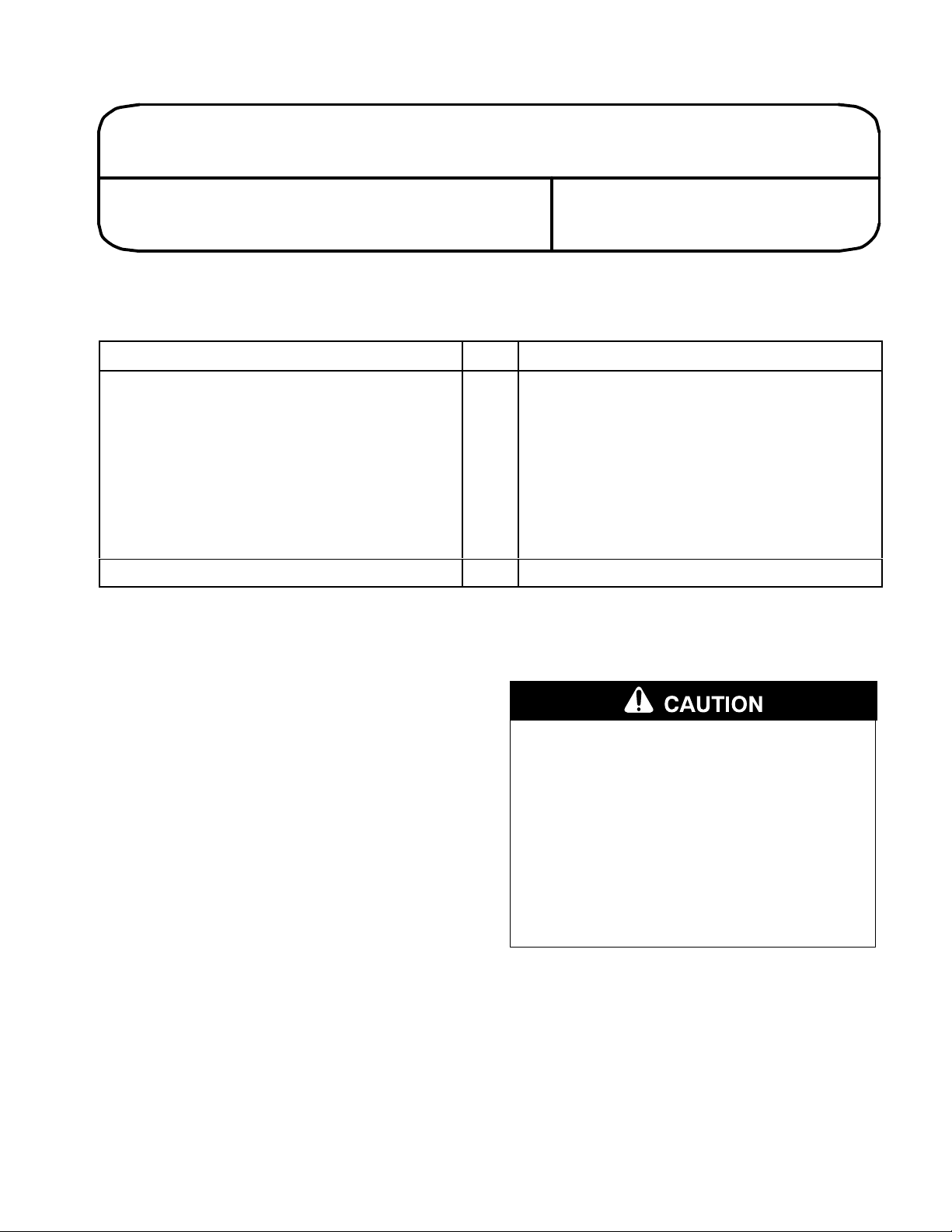
2. Remove the tension spring, shoulder bolt,
tension lever and spring tension link (Fig. 1) and
discard.
INSTALLATION
INSTRUCTIONS
Installation
1. Release the belt tension lever to relieve belt
tension if mounted to a tractor.
POTENTIAL HAZARD
• Spring is under tension.
WHAT CAN HAPPEN
• Stored spring energy can cause personal
injury when r
HOW TO AV
eleased rapidly
OID THE HAZARD
.
• Carefully unhook spring with a firm grip
and r
elease slowly
.
Page 2
2
2
1
m–4084
1
4
3
Figure 1
1. Tension
2. T
spring
ension lever
3.
Spring tension link
4.
Shoulder bolt
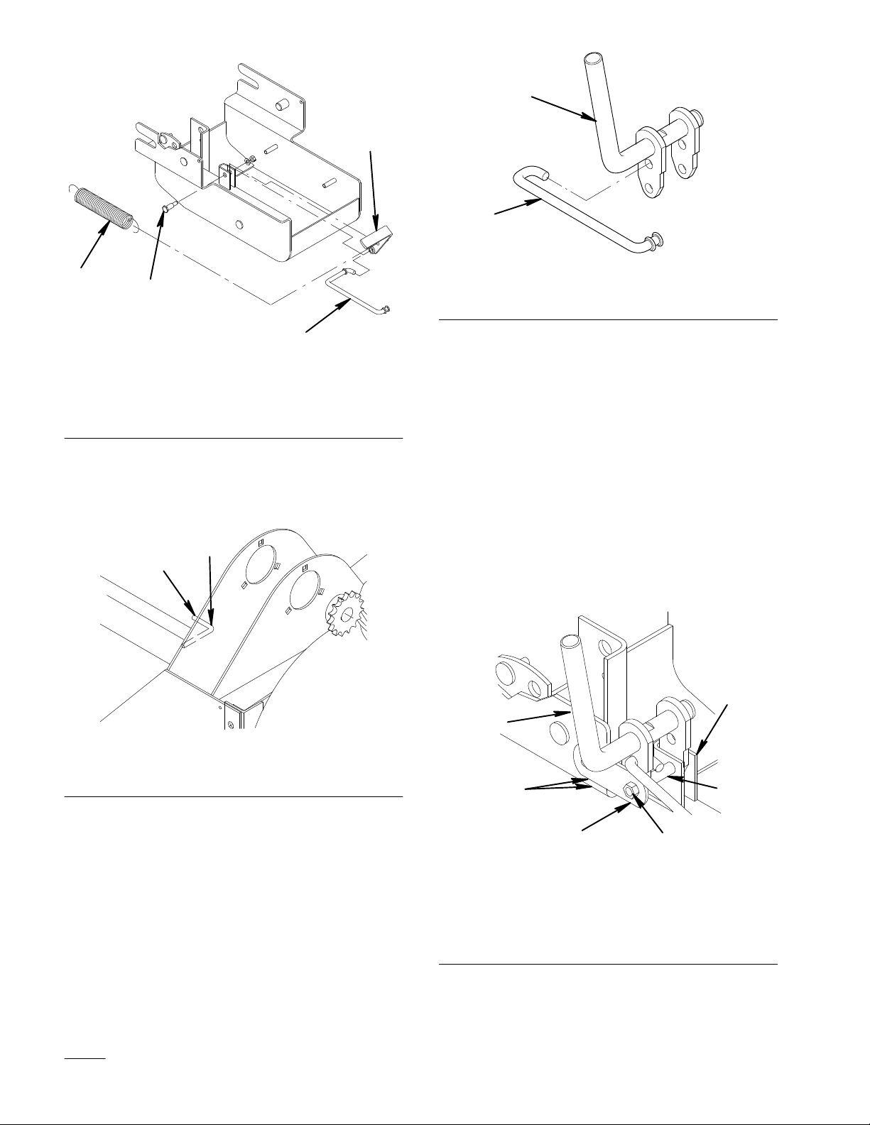
3. With a hacksaw or other suitable tool, cut the
belt guide off at the bend adjacent to the welded
leg (Fig. 2). Grind or file smooth after cutting.
2
1
Figure 3
1. Spring
tension link
2.
Lever assembly
5. Assemble the lever assembly to the pulley box
frame by inserting the leg furthest from the bend
into the frame where the old lever was located
(Fig. 4). Insert the shoulder bolt, with the head
to the inside through the pivot hole and on
through the hole in the second leg. Place the
pivot bracket over the threaded end. Install a
5/16” lock nut and tighten securely (Fig. 4).
6. Rotate the bracket so that the other end aligns
parallel with the bottom of the pulley box (Fig.
4). Clamp in place so that the lever assembly
shaft is aligned 90 degrees to the side of the
pulley box.
m–4083
Figure 2
1. Belt
guide
2. Cut–of
f point
4. Install the double bend end of the spring tension
link in the upper hole of the outer leg (adjacent
to bend) on the lever assembly so that the
extended part of the link is outward in the same
plane as the handle (Fig. 3).
2
1. Lever
2.
Frame bracket
3.
Align edges
1
3
assembly
4
Figure 4
4.
Pivot bracket
5.
5/16” lock nut
6.
Shoulder bolt
2
6
5
m–4087
Page 3
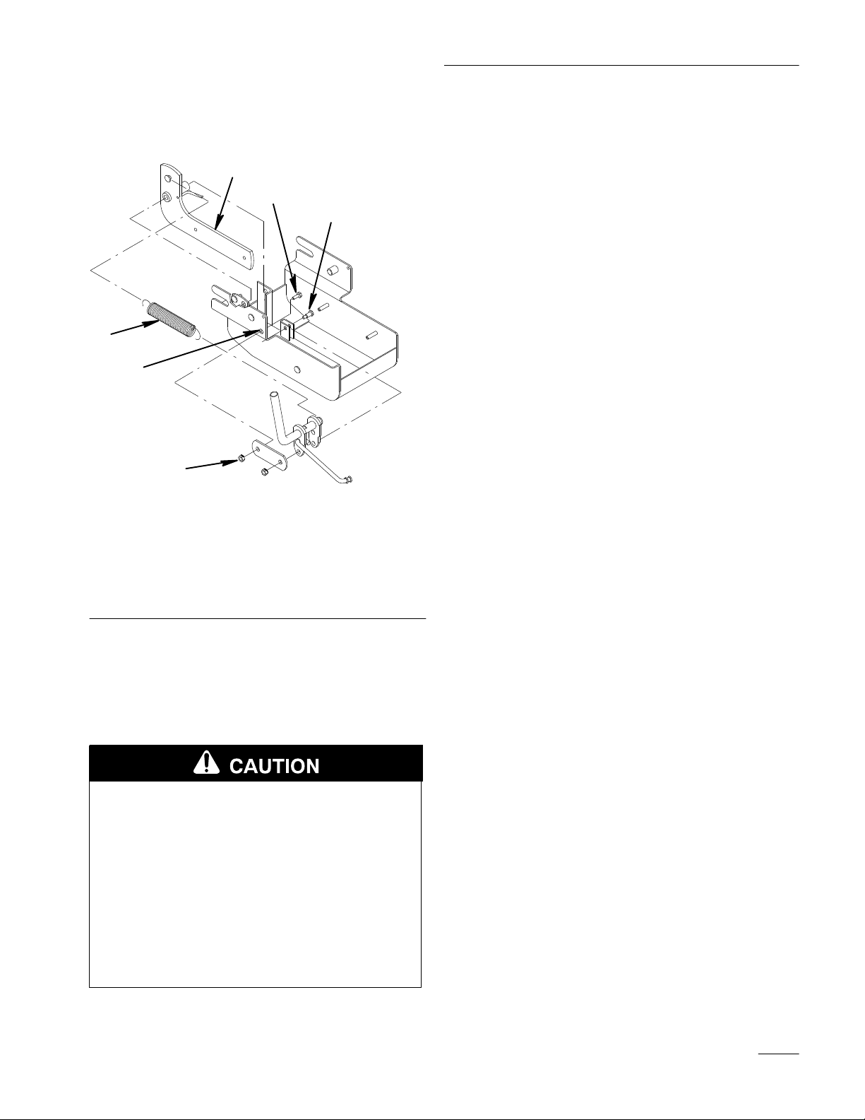
7. Using the hole in the pivot bracket as a template
drill a 11/32” hole in the pulley box leg (Fig. 5).
Insert the 5/16 x 3/4” bolt in this hole. Install a
5/16” nut and tighten securely (Fig. 5).
2
5
3
1
6
Installation Instructions
4
Figure 5
1. Tension
2.
3.
spring (6 7/8” lg.)
Pulley pivot arm
Shoulder bolt
4.
5/16” lock nut
5.
5/16 x 3/4” bolt
6. 1
1/32” drilled hole
8. Attach one end of the supplied new tension
spring (6 7/8” overall length) to the pulley pivot
arm with the open side of the spring hook down.
Attach other end of the spring to the groove in
the end of the lever assembly (Fig. 5).
POTENTIAL HAZARD
• Spring is under tension when installed.
WHAT CAN HAPPEN
• Stored spring energy can cause personal
injury.
m-4085
HOW TO AV
OID THE HAZARD
• Firmly grip the spring when extending and
hook carefully.
3
 Loading...