

Page 1
FORM NO. 3322-419
Enhancement Kit
Part No. 99–0297
Loose
Note: Use the chart below to identify parts for assembly.
DESCRIPTION QTY. USE
Remote Filter
Shear Bolt
Left Hand Bagger Baf
Right Hand Bagger Baf
Left Hand Discharge Baf
Right Hand Discharge Baf
Left Hand Recycler Baf
Right Hand Recycler Baf
Parts
fle
fle
fle
fle
fle
fle
1
1
1
1
1
1
1
1
Install Remote Filter Kit
Install Shear Bolt Kit
Install New Bagger Baf
Install New Discharge Baf
Install New Baf
fles for Recycler
INSTALLATION
INSTRUCTIONS
fles
fles
Retainer Nuts
Hex Head Screws
Washers
Idler Arm Pivot Bolt
Dampers 2
Hopper Back Plate
Washers 3
Rivets 4
Washer 1
The T
oro Company – 1998
Printed in USA
All Rights Reserved
14
14
14
1
2
Install New Retainer Nuts
Install Idler Arm Pivot Bolt
Install Dampers
Install Hopper Back Plate
Install new washer on hopper pegs
Install new rivets
Install W
asher on Blower Pulley for 25hp Units
Page 2
Installation Instructions
Installing
Remote Filter Kit
Refer to the enclosed kit and instructions for
installing this kit.
Installing
Shear Bolt Kit
Refer to the enclosed kit and instructions for
installing this kit.
Installing
Baffles
You will need to remove baffles in order to install all
retaining nuts. Which baffles you have to remove
depends if you are in recycling or bagging mode.
Stop the engine, set the parking brake and remove the
key.
Tilting the deck up will make it easier to install
baffles. See tilting deck on page 8.
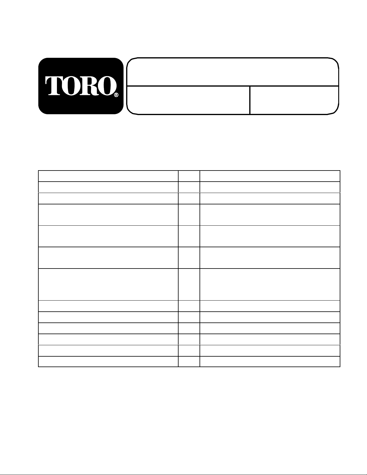
Installing New Discharge Baffles
The discharge baffles are used in the bagging mode.
When in bagging mode, you need to remove the old
baffles in order to install new baffles.
1. Locate the left and right discharge baffles.
Remove carriage bolts and lock nuts that attach
the baffles to the deck (Fig. 1).
2. Install new retainer nuts. See Installing New
Retainer Nuts on page 3.
3. Install new discharge baf
and hex head screws and existing carriage bolt
(Fig. 1).
Note: Remember to reuse the carriage bolt
(Item 6) on the discharge baffle
(Fig. 1).
2
fles using new washers
5
3
6
Stop the engine, set the parking brake and remove the
key.
Installing New Bagger Baffles
The bagger baffles are used in the bagging mode.
When in bagging mode, you need to remove the old
baffles in order to install new baffles.
1. Locate the left and right bagger baffles. Remove
carriage bolts and lock nuts that attach the
baffles to the deck (Fig. 1).
2. Install new retainer nuts. See Installing New
Retainer Nuts on page 3.
3. Install new bagger baf
and hex head screws (Fig. 1)
fles using new washers
5
3
1. Bagger
2.
Retainer Nut
3.
Hex Head Screw
baf
4
1
Figure 1
fle
4.
Discharge baf
5. W
asher (.344x.688)
6.
Carriage Bolt
m–4235
fle
2
Page 3
Installation Instructions
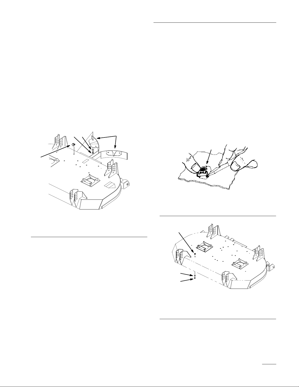
Installing New Baffles for Recycler
The recycler baffles are used in the recycling mode.
When in recycling mode, you need to remove the old
baffles in order to install new baffles.
1. Locate the left and right recycler baffles.
Remove carriage bolts and lock nuts that attach
the baffles to the deck (Fig. 2).
2. Install new retainer nuts. See Installing New
Retainer Nuts on page 3.
3. Install new recycler baf
and hex head screws (Fig. 2).
2
4
fles using new washers
3
1
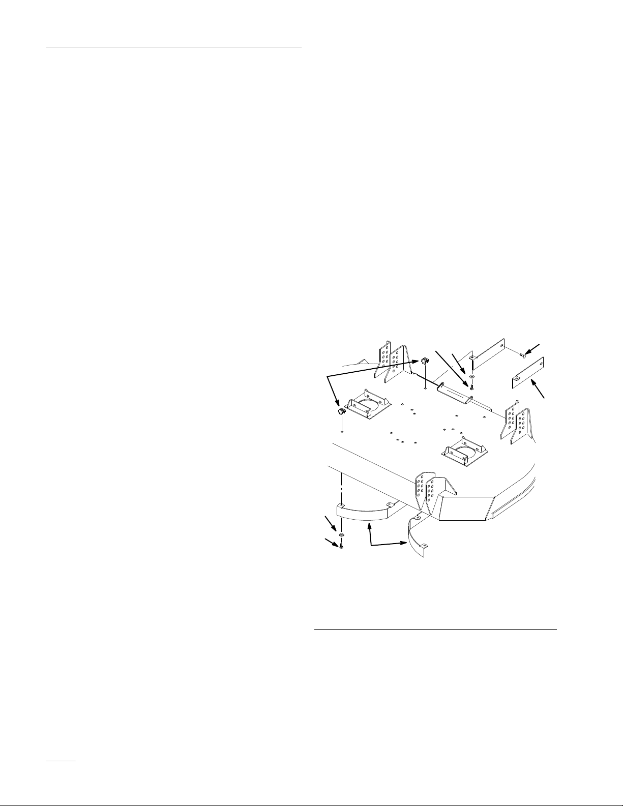
2. Remove baffles if not already done so.
3. On the top surface of the deck, install one
retaining leg into the the square opening of the
deck (Fig. 3 and 4).
4. Push a screw driver into the other leg and insert
retaining nut into square hole (Fig. 3).
5. Install baffles using hex head screws and
washers (Fig. 4).
6. Install all hex head screws and washers into
unused retainer nuts (Fig. 4).
7. When all of the retainer nuts are installed, then
reinstall footrest to deck frame.
1
Figure 2
1. Recycler baf
2.
Hex Head Screw
Installing
fle
3. W
asher (.344x.688)
4.
Retainer Nut
New Retainer Nuts
The retainer nuts in this kit will make the process of
changing between recycler and bagging modes
quicker and easier.
Note: All retaining nuts must be installed in
place of each lock nut used to fasten
baffles to deck.
Use baffles for a template to locate where retainer
nuts are used.
1. Retainer
1
2
3
1. Retainer
2. Washer
Nut
Nut
Figure 3
Figure
4
Hex Head Screw
3.
1. If your foot rest is bolted to the deck frame
remove it. If it is not, proceed to step 2.
3
Page 4

Installation Instructions
Installing
New Idler Arm Pivot
Bolt
The new bolt will prevent the spring to go past bolt or
center and loose tension on spring.
1. Stop the engine, set the parking brake and
remove the key.
2. Locate idler arm. Remove spring from idler arm.
(Fig. 5).
3. Remove bolt from pivot. Save all hardware
except for the bolt (Fig. 5).
4. Install new bolt and hardware (Fig. 5).
Note: Notice how the bolt is installed. The
head must be toward the inside of the
mower (Fig. 5).
5.
Reinstall spring.
Installing
New Dampers
The new dampers provide for less aggressive
operation. This is useful for uneven terrain and new
operators. The old dampers provide a more aggressive
operation and experienced operators may prefer them.
1. Stop the engine, set the parking brake and
remove the key.
2. Tilt seat forward. Dampers are located under seat
(Fig. 6).
3. Remove cotter pins, clevis pins, spacer and
damper (Fig. 6).
4. Install new damper and install with existing
cotter pins, clevis pins and spacer (Fig. 6).
Note: Notice the position of the spacer. It
must be toward the outside of the
machine.
5. Repeat for opposite damper.
7
6
4
3
1. Bolt
2. Washer
3. Locknut
Figure 5
4. Spring
5. Spacer
6. Idler
Arm Pivot
125
m–4237
Note: Old dampers can be reused if desired.
Dampers must be used in matching
pairs.
1
2
3
4
3
4
Figure 6
1. Spacer
2. Damper
3. Cotter
4.
Clevis Pin
Pin
m–4247
4
Page 5

Installation Instructions
Installing
New Collection Bin
Back Plate
The new plates will increase support for the latches.
1. Unlatch and open rear lid on grass collection bin.
2. Remove existing bolts, washers and latch
(Fig. 7).
Note: It may be necessary to remove the bin
flange in order to get proper access to
bolts and washers (Fig. 7).
3. Discard the washers and replace with back plate.
Tighten bolts, back plate and latch (Fig. 7).
4. Repeat for latch on other side of collection bin.
5 6 7
Installing
New W
asher on
Collection Bin Pegs
The new washers will increase support for the latch
pegs.
1. Unlatch and open rear lid on grass collection bin.
2. Remove existing bolt, washer and latch peg
(Fig. 8).
3.
Replace existing washer with new washer
Tighten bolt, washer and latch peg (Fig. 8).
4. Repeat for other two latch pegs on collection bin
(Fig. 8).
.
1. Bolt
2. Back
3. Latch
4.
Plate
Hex Head Screw
1
Figure 7
8 2 5
5. Spacer
6.
Bin Flange
7. Nut
8. W
asher (Discard)
3
4
M-4238
3
2
1. Latch
2. W
asher (.216x.750)
Peg
1
1 2 3
M-4239
Figure 8
3. Screw
5
Page 6

Installation Instructions
Installing
New Rivets on Grass
Collection Bin
Check to see if your metal chute is loose. If it is
loose, replace the rivets.
1. Remove any existing rivets from metal chute
(Fig. 9).
2. Install new rivets. (Fig. 9).
Note: You may have to repeat actuation of a
manual riveting tool until the mandrel
breaks and rivet is set.
1
3
1. Metal
2. Rivets
2
Chute
Figure 9
Collection Bin
3.
M–4240
6
Page 7

Installation Instructions
Installing
New W
asher on
Blower Pulley
Note: This procedure is for mowers with
25hp engines only.
1. Stop the engine, set the parking brake and
remove the key.
2. Push up and hold the spring loaded idler arm,
behind blower to relax pressure on blower belt,
and pin to engine frame (Fig. 11).
3. Remove belt (Fig. 11).
4. Loosen bolts that hold blower to frame (Fig. 10).
Note: It may be necessary to fully remove the
bolts.
5. Remove the bolt and washer on the blower
pulley (Fig. 11).
3
4
1. Screw
2. Washer
Figure 11
3. Belt
4. Spring
2
1
m-4242
Loaded Idler Arm
6. Discard washer and reinstall new washer and
bolt (Fig. 11).
1
2
Figure 10
1. Blower
assembly
2. Bolts
m-4232
7
Page 8

Installation Instructions
Tilting
the Mower
The mower can be tilted up for ease of service.
To Raise Mower
1. Turn engine off, set the parking brake and check
that PTO cover is down against deck (Fig. 12).
2. Lift on the mower carrier frame to release weight
on latch pin and pull out on latch pin to release
(Fig. 12). Lower rear of mower onto anti-scalp
rollers. Repeat on the other side.
3. Return the pins to the spring loaded (down)
position.
4
1
4. Standing in front of the mower, lift up and push
rearward on front to raise mower (Fig. 13).
5. Raise mower until it contacts stops and latch
pins snap into locked position.
1
m–3375
Figure 13
1. Mower
up
3
1. Parking
2. PTO cover
brake
2
Figure 12
3.
4. Notch–open
Latch pin
8
 Loading...