

Page 1
FORM NO. 3321-470
REMOTE OIL FILTER KIT
for OFZ TRACTION UNITS
PART NO. 99-0267
Loose Parts
Note: Use the chart below to identify parts used for assembly.
DESCRIPTION QTY. USE
Filter adapter
O–ring
1/2” NPTF fitting
Oil hose
Remote filter Plate
Bolt 5/16–18 x 1” (26 mm)
Locknut 5/16–18
1/4” NPTF nipple
Remote filter adapter
1
1
2
2
1
4
4
2
1
Install filter adapter and hoses
Install remote oil filter
INSTALLATION
INSTRUCTIONS
Oil filter
Cable tie
Parts Catalog 1 Save for ordering parts
1
1
Note: Coat all threads with pipe joint sealant
before assembly. Do not use teflon
tape.
1
Install Filter Adapter
1. Drain engine oil and remove existing oil filter
from engine. Refer to: traction unit Operator’s
Manual.
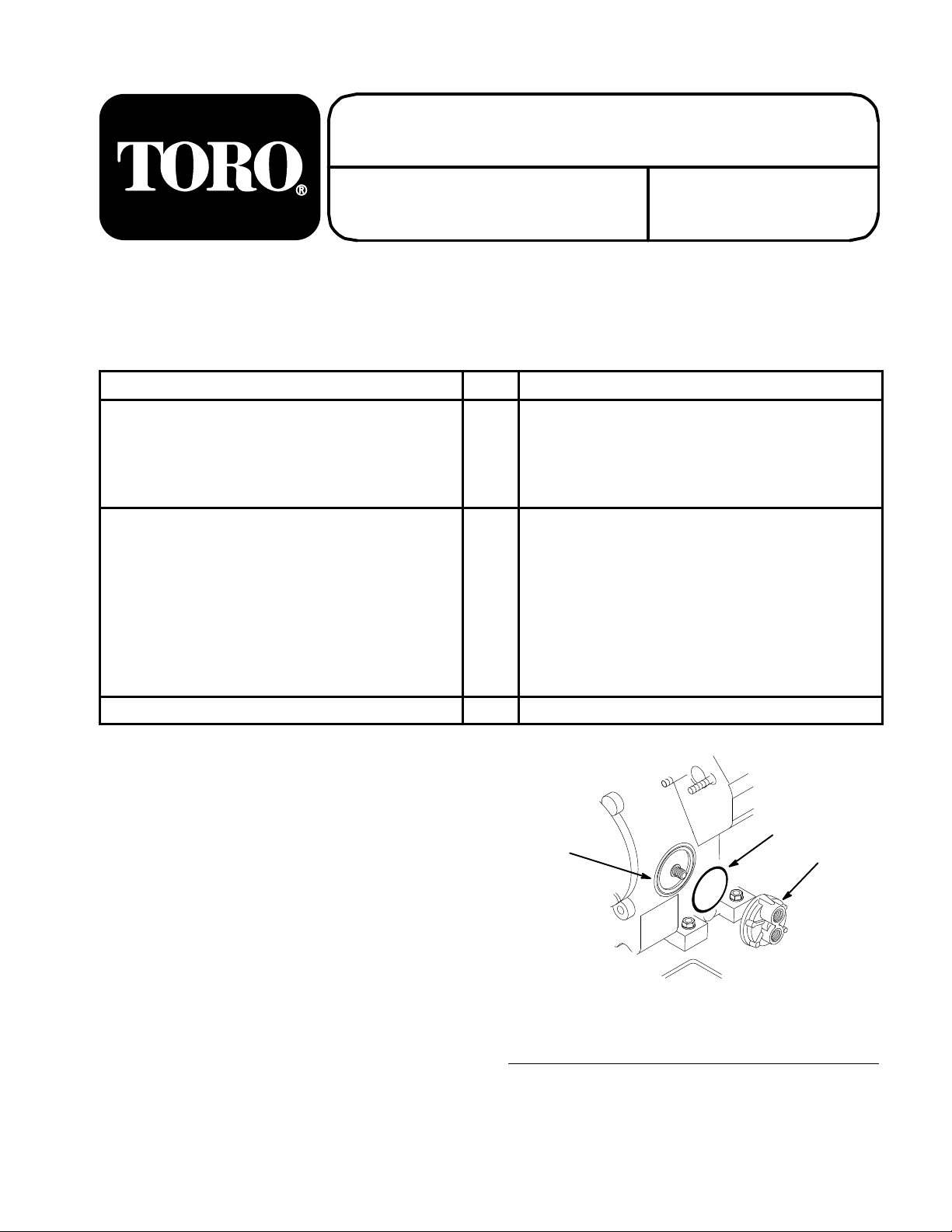
2. Clean engine oil filter mounting surface (Fig. 1).
3. Install O–ring into grove of filter adapter and
thread filter adapter onto engine oil filter
mounting until snug, then turn and additional
1/4 turn and orient as shown (Fig. 1).
1. Oil filter mounting
2. O–ring
2
3
m–3972
Figure 1
3. Filter adapter
Page 2
Install Oil Hoses
Install Remote Filter Adapter
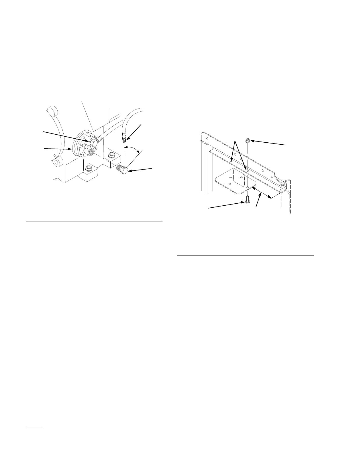
1. Thread 1/2” NPTF fittings into filter adapter.
2. Torque fittings to 90–130 in. lbs. (10–15 N•m)
ending between 12 and 3 o’clock as shown
(Fig. 2).
3. Thread fixed hose ends into 1/2” NPTF fitting
(Fig. 2).
4
5
1
1. Filter adapter
2. 1/2” NPTF fitting
3. Between 12-3 o’clock
Figure 2
4. Oil hose, fixed end
5. OUT port
3
m–3973
1. Measure back 6-1/2” (165 mm) from left frame
upright to front of plate. Center filter plate holes
on flange width and clamp plate in position
(Fig. 3).
2. Using filter plate as a guide, drill (2) 11/32”
(9 mm) mounting holes through bottom flange
of left side engine frame (Fig. 3).
3. Secure filter plate to bottom flange of engine
frame with (2) 5/16-18 x 1” (26 mm) bolts and
(2) 5/16-18 flange locknuts (Fig. 3).
2
4
2
3
1. 6-1/2” (165 mm)
2. Drill (2) 11/32’ (9 mm)
holes in left side engine
frame
1
Figure 3
3. Bolt 5/16-18 x 1” (26 mm)
4. flange locknut 5/16-18
m–3981
2
Page 3

4. Secure remote filter adapter to filter plate with
(2) 5/16-18 x 1” (26 mm) bolts and (2) 5/16-18
flange locknuts (Fig. 4).
11. Apply a thin coat of oil to filter rubber seal and
thread oil filter onto remote filter adapter until it
is snug, then turn an additional 1/2 turn (Fig. 4).
5. Thread (2) 1/4” NPTF fittings into remote filter
adapter.
Note: Engine damage may occur with
incorrect hose location.
6. Torque fittings to 65-80 in. lbs. (7-9 N
•m).
7. Select oil hose from filter adapter “OUT” port
(Fig. 2). Thread oil hose swivel end onto 1/4”
NPTF fitting of remote oil filter mount port “A”
(Fig. 4).
Note: Engine damage may occur with
incorrect hose location.
8. Thread remaining oil hose onto other fitting
(Fig. 4).
9. Torque hose swivel fittings to 65-80 in. lbs.
(7-9 N
•m).
10. Install cable tie around oil hoses and secure to
fuel pump inlet or hydraulic hoses to prevent
contact with blower belt or pulley.
12. Install drain plug and fill engine with oil. Refer
to: traction unit Operator’s Manual.
13. Run engine and check for oil leaks.
3
1
7
4
2
5
1. Remote filter adapter
2. Bolt 5/1618 x 1” (26 mm)
3. flange locknut 5/16-18
4. 1/4” NPTF fitting
Figure 4
5. Port A (outer)
6. Oil hose, swivel end
7. Oil filter
m–3974
6
3
Page 4

 Loading...