

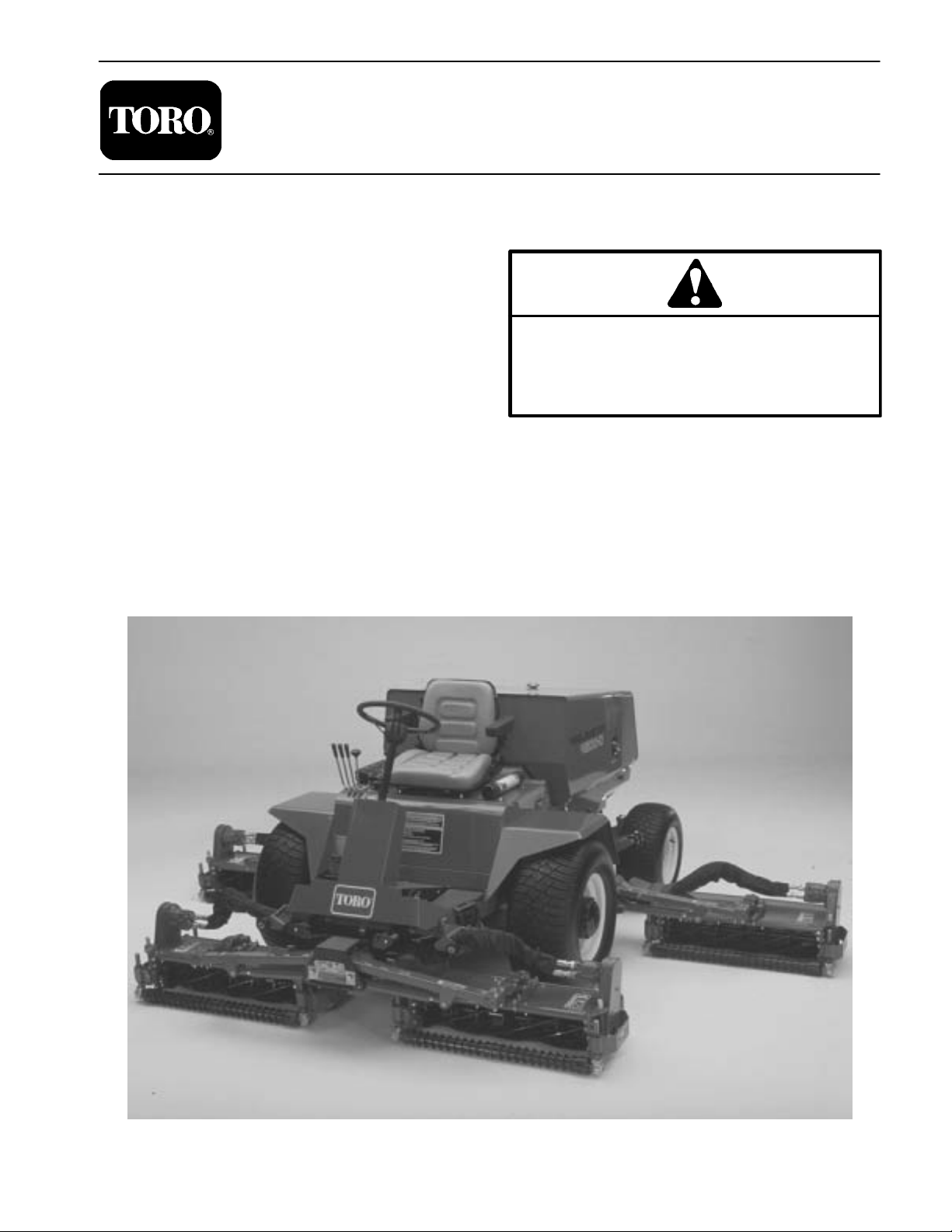
Page 1
Preface
The purpose of this publication is to provide the service
technician with information for troubleshooting, testing,
and repair of major systems and components on the
Reelmaster 4000–D.
REFER TO THE TRACTION UNIT AND CUTTING
UNIT OPERATOR’S MANUALS FOR OPERATING,
MAINTENANCE AND ADJUSTMENT INSTRUCTIONS. Space is provided in Chapter 2 of this book to
insert the Operator’s Manuals and Parts Catalogs for
your machine. Replacement Operator’s Manuals are
available by sending complete Model and Serial Number to:
PART NO. 98958SL, Rev. A
Service Manual
ReelmasterR 4000–D
This safety symbol means DANGER, WARNING,
or CAUTION, PERSONAL SAFETY INSTRUCTION. When you see this symbol, carefully read
the instructions that follow. Failure to obey the
instructions may result in personal injury.
NOTE: A NOTE will give general information about the
correct operation, maintenance, service, testing, or repair of the machine.
The Toro Company
8111 Lyndale Avenue South
Bloomington, MN 55420–1196
The Toro Company reserves the right to change product
specifications or this publication without notice.
IMPORTANT: The IMPORTANT notice will give important instructions which must be followed to prevent damage to systems or components on the
machine.
E The Toro Company – 1998, 2003
Page 2

Reelmaster 4000–D
Page 3

Table Of Contents
Chapter 1 – Safety
General Safety Instructions 1 – 1. . . . . . . . . . . . . . . . . .
Safety and Instruction Decals 1 – 4. . . . . . . . . . . . . . . .
Chapter 2 – Product Records and Manuals
Product Records 2 – 1. . . . . . . . . . . . . . . . . . . . . . . . . . .
Equivalents and Conversions 2 – 2. . . . . . . . . . . . . . . .
Torque Specifications 2 – 3. . . . . . . . . . . . . . . . . . . . . . .
Lubrication 2 – 7. . . . . . . . . . . . . . . . . . . . . . . . . . . . . . . .
Operation and Service History Reports 2 – 8. . . . . . . .
Chapter 3 – Kubota Diesel Engine
Introduction 3 – 2. . . . . . . . . . . . . . . . . . . . . . . . . . . . . . . .
Specifications 3 – 3. . . . . . . . . . . . . . . . . . . . . . . . . . . . . .
General Information 3 – 4. . . . . . . . . . . . . . . . . . . . . . . .
Adjustments 3 – 7. . . . . . . . . . . . . . . . . . . . . . . . . . . . . . .
Service and Repairs 3 – 8. . . . . . . . . . . . . . . . . . . . . . . .
KUBOTA WORKSHOP MANUAL, 03 SERIES,
DIESEL ENGINE
Chapter 4 – Hydraulic System
Specifications 4 – 2. . . . . . . . . . . . . . . . . . . . . . . . . . . . . .
General 4 – 3. . . . . . . . . . . . . . . . . . . . . . . . . . . . . . . . . . .
Hydraulic Schematic 4 – 8. . . . . . . . . . . . . . . . . . . . . . . .
Hydraulic Flow Diagrams 4 – 9. . . . . . . . . . . . . . . . . . . .
4WD Selector Valve Operation 4 – 24. . . . . . . . . . . . . .
Special Tools 4 – 26. . . . . . . . . . . . . . . . . . . . . . . . . . . . .
Troubleshooting 4 – 28. . . . . . . . . . . . . . . . . . . . . . . . . . .
Testing 4 – 30. . . . . . . . . . . . . . . . . . . . . . . . . . . . . . . . . . .
Service and Repairs 4 – 39. . . . . . . . . . . . . . . . . . . . . . .
Chapter 5 – Electrical System
Electrical Schematics and Diagrams 5 – 2. . . . . . . . . .
Special Tools 5 – 13. . . . . . . . . . . . . . . . . . . . . . . . . . . . .
Troubleshooting 5 – 14. . . . . . . . . . . . . . . . . . . . . . . . . . .
Electrical System Quick Checks 5 – 17. . . . . . . . . . . . .
Component Testing 5 – 18. . . . . . . . . . . . . . . . . . . . . . . .
Service and Repairs 5 – 29. . . . . . . . . . . . . . . . . . . . . . .
Chapter 6 – Axles and Brakes
Specifications 6 – 2. . . . . . . . . . . . . . . . . . . . . . . . . . . . . .
Adjustments 6 – 3. . . . . . . . . . . . . . . . . . . . . . . . . . . . . . .
Service and Repairs 6 – 5. . . . . . . . . . . . . . . . . . . . . . . .
SafetyProduct Records
and Manuals
Engine
Chapter 7 – Cutting Units
Specifications 7 – 2. . . . . . . . . . . . . . . . . . . . . . . . . . . . . .
Special Tools 7 – 3. . . . . . . . . . . . . . . . . . . . . . . . . . . . . .
Adjustments 7 – 4. . . . . . . . . . . . . . . . . . . . . . . . . . . . . . .
Service and Repairs 7 – 8. . . . . . . . . . . . . . . . . . . . . . . .
System
Hydraulic
System
Electrical
Brakes
Axles andCutting Units
Reelmaster 4000–D
Page 4

Reelmaster 4000–D
Page 5
Table of Contents
Chapter 1
Safety
GENERAL SAFETY INSTRUCTIONS 1. . . . . . . . . . . .
Before Operating 1. . . . . . . . . . . . . . . . . . . . . . . . . . . .
While Operating 2. . . . . . . . . . . . . . . . . . . . . . . . . . . .
Maintenance and Service 3. . . . . . . . . . . . . . . . . . . .
General Safety Instructions
The Reelmaster 4000–D was tested and certified by
TORO for compliance with the B71.4–1984 specifications of the American National Standards Institute for
riding mowers when rear tires are filled with calcium
chloride and two rear wheel weight kits. Although hazard control and accident prevention partially are dependent upon the design and configuration of the machine,
these factors are also dependent upon the awareness,
concern, and proper training of the personnel involved
in the operation, transport, maintenance, and storage of
the machine. Improper use or maintenance of the machine can result in injury or death.
Before Operating
1. Read and understand the contents of the traction
unit and cutting unit operator’s manuals before operating the machine. To get replacement manuals, send
complete model and serial number to:
The Toro Company
8111 Lyndale Avenue South
Minneapolis, MN 55420–1196
2. Never allow children to operate the machine or
adults to operate it without proper instruction.
3. Become familiar with the controls and know how to
stop the machine and engine quickly.
4. Keep all shields, safety devices and decals in place.
If a shield, safety device or decal is defective or damaged, repair or replace it before operating the machine.
SAFETY AND INSTRUCTION DECALS 4. . . . . . . . . .
WARNING
To reduce the potential for injury or death,
comply with the following safety instructions.
6. Wearing safety glasses, safety shoes, long pants
and a helmet is advisable and required by some local ordinances and insurance regulations.
7. Make sure the work area is clear of objects which
might be picked up and thrown by the reels.
8. Do not carry passengers on the machine. Keep everyone, especially children and pets, away from the
areas of operation.
9. Since diesel fuel is highly flammable, handle it carefully:
A. Use an approved fuel container.
B. Do not remove fuel tank cap while engine is hot
or running.
Safety
5. Always wear substantial shoes. Do not operate machine while wearing sandals, tennis shoes, sneakers or
when barefoot. Do not wear loose fitting clothing that
could get caught in moving parts and possibly cause
personal injury.
Reelmaster 4000–D
Page 1 – 1
C. Do not smoke while handling fuel.
D. Fill fuel tank outdoors and only to within an inch
(25 mm) from the top of the tank, not the filler neck.
Do not overfill.
E. Wipe up any spilled fuel.
Safety
Page 6

While Operating
10. Do not run engine in a confined area without adequate ventilation. Exhaust is hazardous and could be
deadly.
1 1. Sit on the seat when starting and operating the machine.
12. Check interlock switches daily for proper operation.
If a switch fails, replace it before operating the machine.
The interlock system is for your protection, so do not bypass it. Replace all interlock switches every two years.
13. This product may exceed noise levels of 85 dB(A)
at the operator position. Ear protectors are recommended for prolonged exposure to reduce the potential
of permanent hearing damage.
14. Before starting the engine each day, test lamps,
warning buzzer and signal lights to assure proper operation.
15. Pay attention when using the machine. To prevent
loss of control:
A. Mow only in daylight or when there is good artificial light.
B. Watch for holes or other hidden hazards.
C. Be extremely careful when operating close to
sand traps, ditches, creeks, steep hillsides or other
hazards.
D. Reduce speed when making sharp turns. Avoid
sudden stops and starts. Use ground speed limiter
lever to set pedal travel so excessive ground speed
will be avoided during mowing and transport.
17. Traverse slopes carefully. Do not start or stop suddenly when traveling uphill or downhill.
18. Operator must be skilled and trained in how to drive
on hillsides. Failure to use caution on slopes or hills may
cause loss of control and vehicle to tip or roll possibly resulting in personal injury or death.
19. When operating 4 wheel drive machine, always use
the seat belt and ROPS together and have seat pivot retaining pin installed.
20. If engine stalls or loses headway and cannot make
it to the top of a slope, do not turn machine around. Always back slowly straight down the slope.
21. Raise cutting units and latch them securely in transport position before driving from one work area to another.
22. Do not touch engine, muffler or exhaust pipe while
engine is running or soon after it is stopped. These areas
could be hot enough to cause burns.
23. If cutting unit strikes a solid object or vibrates abnormally, stop immediately, turn engine off, set parking
brake and wait for all motion to stop. Inspect for damage.
If reel or bedknife is damaged, repair or replace it before
operating. Do not attempt to free blocked cutting unit by
moving Mow/Backlap lever rapidly between FORWARD
and BACKLAP . Damage to hydraulic system may result.
Lever should easily return and hold in the STOP position.
24. Before getting off the seat:
A. Move traction pedal to neutral.
E. Look to the rear to assure no one is behind the
machine before backing up.
F . Watch for traffic when near or crossing roads. Always yield the right–of–way.
G. Reduce speed when driving downhill.
16. Keep hands, feet, andclothing away from moving
parts and the reels.
Safety
Page 1 – 2
B. Set parking brake.
C. Disengage cutting units and wait for reels to
stop.
D. Stop engine and remove key from switch.
E. Do not park on slopes unless wheels are
chocked or blocked.
25. The optional TORO tow bar is for emergency towing
only. Use only the special tow bar if it becomes necessary to tow machine. Use trailer for normal transport.
Reelmaster 4000–D
Page 7

Maintenance and Service
26. Before servicing or making adjustments, stop engine and remove key from the switch.
27. Assure entire machine is properly maintained and
in good operating condition. Frequently check all nuts,
bolts and screws.
28. Frequently check all hydraulic line connectors and
fittings. Assure all hydraulic hoses and lines are in good
condition before applying pressure to the system.
29. Keep body and hands away from pin hole leaks or
nozzles that eject high pressure hydraulic fluid. Use
cardboard or paper to find hydraulic leaks. Hydraulic
fluid escaping under pressure can penetrate skin and
cause injury. Fluid accidentally injected into the skin
must be surgically removed within a few hours by a doctor or gangrene may occur.
30. Before any hydraulic system maintenance, stop engine and lower cutting units to the ground so all pressure
is relieved.
31. For major repairs or other assistance, contact your
local Toro Distributor.
32. To reduce potential fire hazard, keep engine area
free of excessive grease, grass, leaves and dirt. Clean
protective screen on back of engine frequently.
33. If engine must be running to perform maintenance
or an adjustment, keep hands, feet, clothing and other
parts of the body away from cutting units and other moving parts. Keep everyone away.
34. Do not overspeed the engine by changing governor
setting. Maximum engine speed is 2500 rpm + or – 100
rpm. T o assure safety and accuracy , have an Authorized
Toro Distributor check maximum engine speed.
35. Shut engine off before checking or adding oil to the
crankcase.
Safety
36. Disconnect battery before servicing the machine. If
battery voltage is required for troubleshooting or test
procedures, temporarily connect the battery.
37. T oro recommends that two people be used to backlap reels. Each person has specific duties and you must
communicate with one another.
38. For optimum performance and safety , use genuine
Toro replacement parts and accessories. Replacement
parts and accessories made by other manufacturers
could be dangerous and may void the product warranty
of The Toro Company.
39. When changing attachments, tires, or performing
other service, use correct blocks, hoists, and jacks.
Make sure machine is parked on a solid level floor such
as a concrete floor. Prior to raising the machine, remove
any attachments that may interfere with the safe and
proper raising of the machine. Always chock or block
wheels. Used jack stands or solid wood blocks to support the raised machine. If the machine is not properly
supported by blocks or jack stands, the machine may
move or fall, which may result in personal injury.
Reelmaster 4000–D
Page 1 – 3
Safety
Page 8
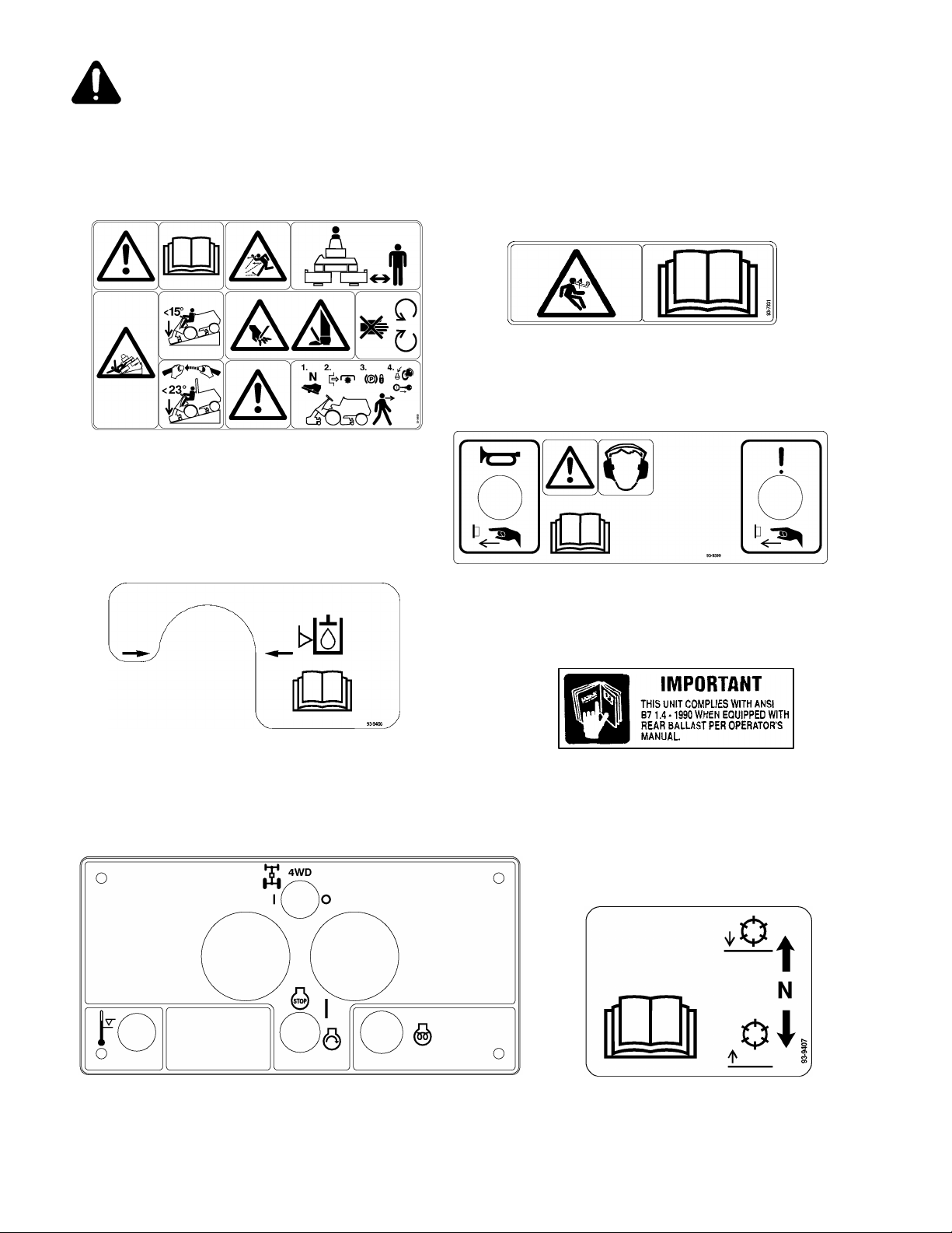
Safety and Instruction Decals
The following safety and instruction decals are installed on the Reelmaster 4000–D. If any become damaged
or illegible, replace them. Decal part numbers are listed below and in the parts catalog. Order replacements
from your Authorized Toro Distributor.
ON LIFT ARMS
(Part No. 93–7331)
ON PANEL IN FRONT OF OPERATOR’S SEAT
(Part No. 93–9408)
ON LEFT SIDE OF MACHINE
(Part No. 93–9406)
ON STEERING CONSOLE
(Part No. 93–9399)
ON FRAME ABOVE RIGHT REAR WHEEL
(Part No. 88–6700)
Safety
ON RIGHT CONTROL PANEL
(Part No. 98–3830)
Page 1 – 4
NEXT TO LIFT LEVERS
(Part No. 93–9407)
Reelmaster 4000–D
Page 9
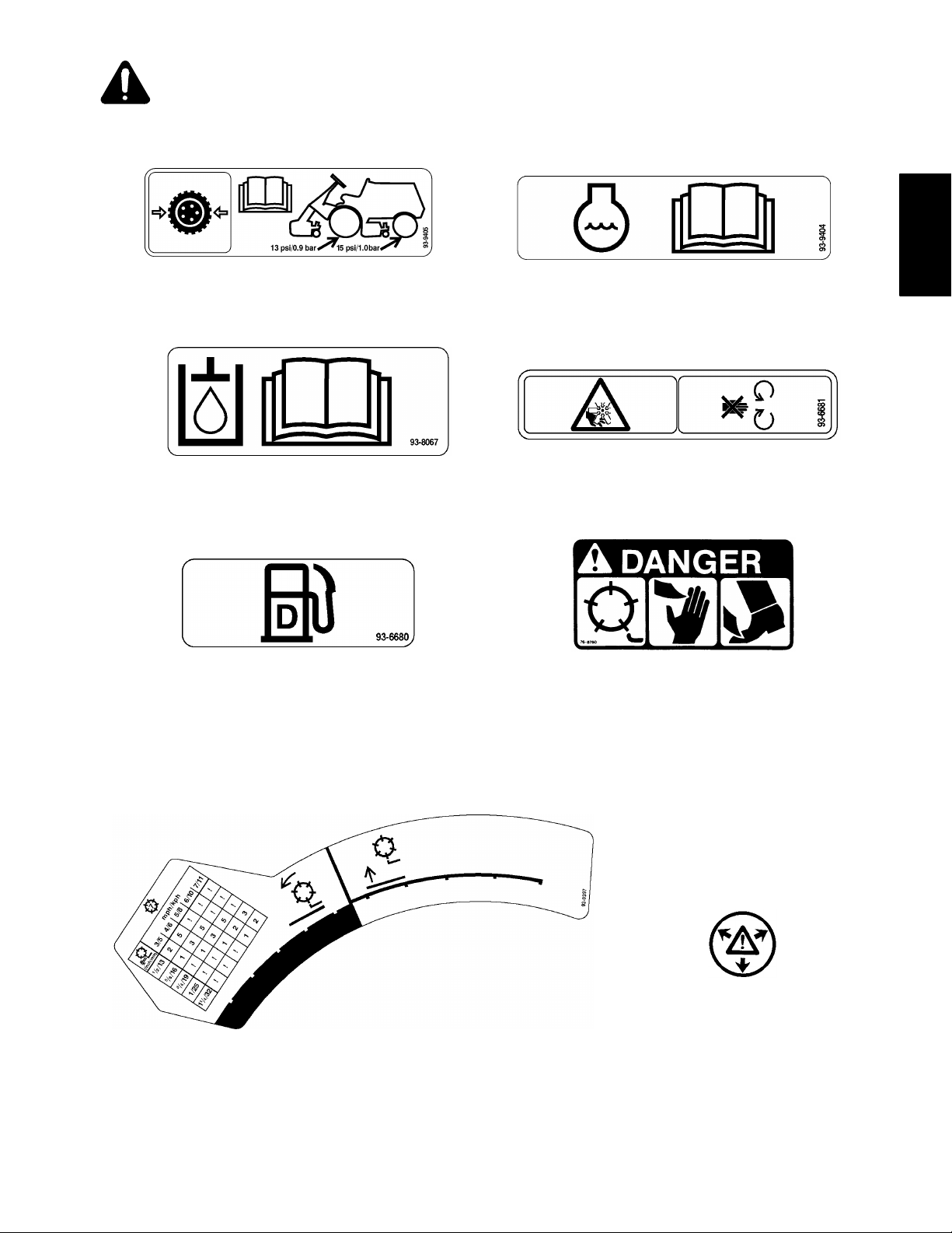
Safety and Instruction Decals
ON FRAME ABOVE REAR WHEELS
(Part No.93–9405)
UNDER SEAT NEAR OIL FILL CAP
(Part No. 93–8067)
Safety
NEAR RADIA T OR FILL CAP
(Part No. 93–9404)
ON FAN SHROUD
(Part No. 93–6681)
NEAR FUEL TANK FILL CAP
(Part No. 93–6680)
NEXT TO TRACTION PEDAL ON STEERING CONSOLE
(Part No. 93–9397)
ON CUTTING UNIT
(Part No. 76–8760)
ON RADIA TOR CAP
(Part No. 59–8440)
Reelmaster 4000–D
Page 1 – 5
Safety
Page 10
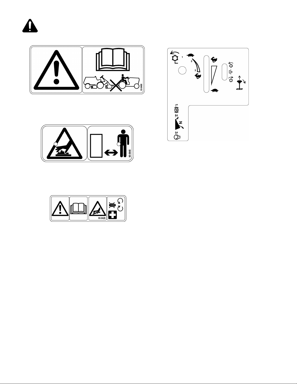
Safety and Instruction Decals
ON FRONT CARRIER & TOW BAR
(Part No. 93–9400)
ON RIGHT CONTROL PANEL
(Part No. 93–9402)
ON EXHAUST SHIELD
(Part No. 95–0645)
ON FRONT ACCESS PANEL
(Part No. 93–9425)
Safety
Page 1 – 6
Reelmaster 4000–D
Page 11

Product Records and Maintenance
Table of Contents
Chapter 2
PRODUCT RECORDS 1. . . . . . . . . . . . . . . . . . . . . . . . .
EQUIVALENTS AND CONVERSIONS 2. . . . . . . . . . .
Decimal and Millimeter Equivalents 2. . . . . . . . . . . .
U.S. to Metric Conversions 2. . . . . . . . . . . . . . . . . . .
Product Records
Record maintenance and repair information about your
Reelmaster 4000–D on the OPERATION AND SERVICE HISTORY REPORT form. Use this information
when referring to your machine.
TORQUE SPECIFICATIONS 3. . . . . . . . . . . . . . . . . . .
Fastener Identification 3. . . . . . . . . . . . . . . . . . . . . . .
Standard Torque for Dry, Zinc Plated, and
Steel Fasteners (Inch Series) 4. . . . . . . . . . . . . . .
Standard Torque for Dry, Zinc Plated, and
Steel Fasteners (Metric Fasteners) 5. . . . . . . . . .
Other Torque Specifications 6. . . . . . . . . . . . . . . . . .
Conversion Factors 6. . . . . . . . . . . . . . . . . . . . . . . . .
LUBRICA TION 7. . . . . . . . . . . . . . . . . . . . . . . . . . . . . . . .
OPERATION & SERVICE HISTORY REPORTS 9. . .
Insert Operator’s Manuals and Parts Catalogs for your
Reelmaster 4000–D at the end of this section.
and Manuals
Product Records
Reelmaster 4000–D
Page 2 – 1
Product Records and Maintenance
Page 12
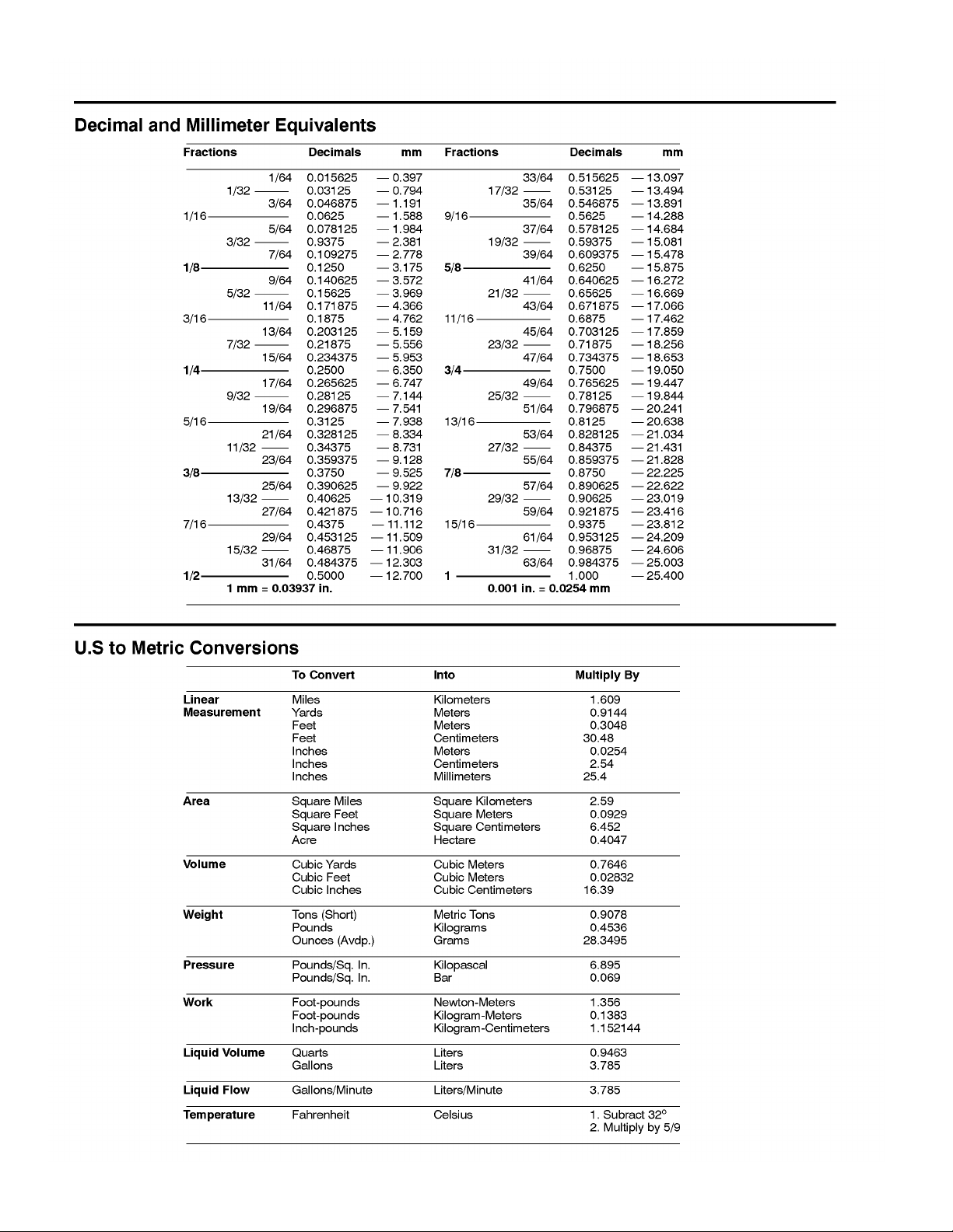
Equivalents and Conversions
Product Records and Maintenance
Page 2 – 2
Reelmaster 4000–D
Page 13
Torque Specifications
Recommended fastener torque values are listed in the
following tables. For critical applications, as determined
by T oro, either the recommended torque or a torque that
is unique to the application is clearly identified and specified in this Service Manual.
These Torque Specifications for the installation and
tightening of fasteners shall apply to all fasteners which
do not have a specific requirement identified in this Service Manual. The following factors shall be considered
when applying torque: cleanliness of the fastener, use
of a thread sealant (Loctite), degree of lubrication on the
fastener, presence of a prevailing torque feature, hardness of the surface underneath the fastener’s head, or
similar condition which affects the installation.
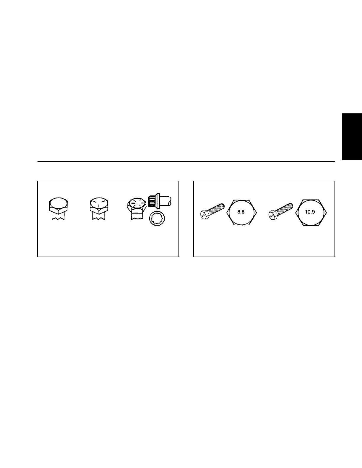
Fastener Identification
As noted in the following tables, torque values should be
reduced by 25% for lubricated fasteners to achieve
the similar stress as a dry fastener. Torque values may
also have to be reduced when the fastener is threaded
into aluminum or brass. The specific torque value
should be determined based on the aluminum or brass
material strength, fastener size, length of thread engagement, etc.
The standard method of verifying torque shall be performed by marking a line on the fastener (head or nut)
and mating part, then back off fastener 1/4 of a turn.
Measure the torque required to tighten the fastener until
the lines match up.
and Manuals
Product Records
Inch Series Bolts and Screws
Metric Bolts and Screws
Reelmaster 4000–D
Page 2 – 3
Product Records and Maintenance
Page 14
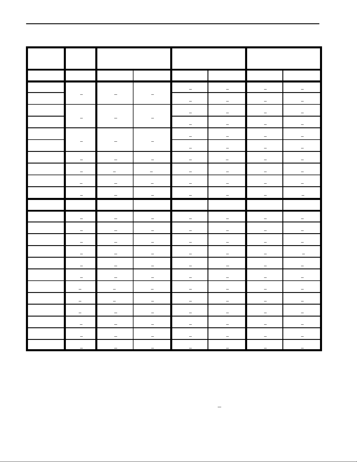
Standard Torque for Dry, Zinc Plated, and Steel Fasteners (Inch Series)
10
2
13
2
147
23
13
2
25
5
282
30
18
2
30
5
339
56
Grade 1, 5, &
Thread Size
# 6 – 32 UNC
# 6 – 40 UNF
# 8 – 32 UNC
# 8 – 36 UNF
# 10 – 24 UNC
# 10 – 32 UNF
1/4 – 20 UNC 48 + 7 53 + 7 599 + 79 100 + 10 1125 + 100 140 + 15 1580 + 170
1/4 – 28 UNF 53 + 7 65 + 10 734 + 113 115 + 10 1300 + 100 160 + 15 1800 + 170
5/16 – 18 UNC 115 + 15 105 + 17 1186 + 169 200 + 25 2250 + 280 300 + 30 3390 + 340
5/16 – 24 UNF 138 + 17 128 + 17 1446 + 192 225 + 25 2540 + 280 325 + 30 3670 + 340
3/8 – 16 UNC 16 + 2 16 + 2 22 + 3 30 + 3 41 + 4 43 + 4 58 + 5
8 with Thin
Height Nuts
in–lb in–lb N–cm in–lb N–cm in–lb N–cm
+
+
+
ft–lb ft–lb N–m ft–lb N–m ft–lb N–m
SAE Grade 1 Bolts, Screws, Studs, &
Sems with Regular Height Nuts
(SAE J995 Grade 2 or Stronger Nuts)
+
+
+
+
+
+
SAE Grade 5 Bolts, Screws, Studs, &
Sems with Regular Height Nuts
(SAE J995 Grade 2 or Stronger Nuts)
15 + 2 170 + 20 23 + 2 260 + 20
17 + 2 190 + 20 25 + 2 280 + 20
29 + 3 330 + 30 41 + 4 460 + 45
31 + 3 350 + 30 43 + 4 485 + 45
42 + 4 475 + 45 60 + 6 675 + 70
48 + 4 540 + 45 68 + 6 765 + 70
SAE Grade 8 Bolts, Screws, Studs, &
Sems with Regular Height Nuts
(SAE J995 Grade 5 or Stronger Nuts)
3/8 – 24 UNF 17 + 2 18 + 2 24 + 3 35 + 3 47 + 4 50 + 4 68 + 5
7/16 – 14 UNC 27 + 3 27 + 3 37 + 4 50 + 5 68 + 7 70 + 7 95 + 9
7/16 – 20 UNF 29 + 3 29 + 3 39 + 4 55 + 5 75 + 7 77 + 7 104 + 9
1/2 – 13 UNC 30 + 3 48 + 7 65 + 9 75 + 8 102 + 11 105 + 10 142 + 14
1/2 – 20 UNF 32 + 3 53 + 7 72 + 9 85 + 8 115 + 11 120 + 10 163 + 14
5/8 – 11 UNC 65 + 10 88 + 12 119 + 16 150 + 15 203 + 20 210 + 20 285 + 27
5/8 – 18 UNF 75 + 10 95 + 15 129 + 20 170 + 15 230 + 20 240 + 20 325 + 27
3/4 – 10 UNC 93 + 12 140 + 20 190 + 27 265 + 25 359 + 34 375 + 35 508 + 47
3/4 – 16 UNF 115 + 15 165 + 25 224 + 34 300 + 25 407 + 34 420 + 35 569 + 47
7/8 – 9 UNC 140 + 20 225 + 25 305 + 34 430 + 45 583 + 61 600 + 60 813 + 81
7/8 – 14 UNF 155 + 25 260 + 30 353 + 41 475 + 45 644 + 61 660 + 60 895 + 81
Note: Reduce torque values listed in the table above
by 25% for lubricated fasteners. Lubricated fasteners
on the fastener size, the aluminum or base material
strength, length of thread engagement, etc.
are defined as threads coated with a lubricant such as
oil, graphite, or thread sealant such as Loctite.
Note: The nominal torque values listed above for
Grade 5 and 8 fasteners are based on 75% of the miniNote: Torque values may have to be reduced when
installing fasteners into threaded aluminum or brass.
The specific torque value should be determined based
mum proof load specified in SAE J429. The tolerance is
approximately +
10% of the nominal torque value. Thin
height nuts include jam nuts.
Product Records and Maintenance
Page 2 – 4
Reelmaster 4000–D
Page 15
Standard Torque for Dry, Zinc Plated, and Steel Fasteners (Metric Fasteners)
Thread Size
Regular Height Nuts
Regular Height Nuts
Class 8.8 Bolts, Screws, and Studs with
(Class 8 or Stronger Nuts)
M5 X 0.8 57 + 5 in–lb 640 + 60 N–cm 78 + 7 in–lb 885 + 80 N–cm
M6 X 1.0 96 + 9 in–lb 1018 + 100 N–cm 133 + 13 in–lb 1500 + 150 N–cm
M8 X 1.25 19 + 2 ft–lb 26 + 3 N–m 27 + 2 ft–lb 36 + 3 N–m
M10 X 1.5 38 + 4 ft–lb 52 + 5 N–m 53 + 5 ft–lb 72 + 7 N–m
M12 X 1.75 66 + 7 ft–lb 90 + 10 N–m 92 + 9 ft–lb 125 + 12 N–m
M16 X 2.0 166 + 15 ft–lb 225 + 20 N–m 229 + 22 ft–lb 310 + 30 N–m
M20 X 2.5 325 + 33 ft–lb 440 + 45 N–m 450 + 37 ft–lb 610 + 50 N–m
Note: Reduce torque values listed in the table above
by 25% for lubricated fasteners. Lubricated fasteners
are defined as threads coated with a lubricant such as
oil, graphite, or thread sealant such as Loctite.
Note: Torque values may have to be reduced when
installing fasteners into threaded aluminum or brass.
The specific torque value should be determined based
on the fastener size, the aluminum or base material
strength, length of thread engagement, etc.
Note: The nominal torque values listed above are
based on 75% of the minimum proof load specified in
SAE J1 199. The tolerance is approximately +
nominal torque value.
Class 10.9 Bolts, Screws, and Studs with
(Class 10 or Stronger Nuts)
and Manuals
Product Records
10% of the
Reelmaster 4000–D
Page 2 – 5
Product Records and Maintenance
Page 16
Other Torque Specifications
Th
Si
B
*
SAE Grade 8 Steel Set Screws
Recommended Torque
read Size
Square Head Hex Socket
1/4 – 20 UNC 140 + 20 in–lb 73 + 12 in–lb
5/16 – 18 UNC 215 + 35 in–lb 145 + 20 in–lb
3/8 – 16 UNC 35 + 10 ft–lb 18 + 3 ft–lb
1/2 – 13 UNC 75 + 15 ft–lb 50 + 10 ft–lb
Thread Cutting Screws
(Zinc Plated Steel)
Type 1, Type 23, or Type F
Thread Size Baseline Torque*
No. 6 – 32 UNC 20 + 5 in–lb
Wheel Bolts and Lug Nuts
Thread Size Recommended Torque**
7/16 – 20 UNF
Grade 5
1/2 – 20 UNF
Grade 5
M12 X 1.25
Class 8.8
M12 X 1.5
Class 8.8
** For steel wheels and non–lubricated fasteners.
Thread Cutting Screws
Thread
ze
No. 6 18 20 20 + 5 in–lb
Threads per Inch
Type A Type B
65 + 10 ft–lb 88 + 14 N–m
80 + 10 ft–lb 108 + 14 N–m
80 + 10 ft–lb 108 + 14 N–m
80 + 10 ft–lb 108 + 14 N–m
(Zinc Plated Steel)
aseline Torque
No. 8 – 32 UNC 30 + 5 in–lb
No. 10 – 24 UNC 38 + 7 in–lb
1/4 – 20 UNC 85 + 15 in–lb
5/16 – 18 UNC 110 + 20 in–lb
3/8 – 16 UNC 200 + 100 in–lb
Conversion Factors
in–lb X 11.2985 = N–cm N–cm X 0.08851 = in–lb
ft–lb X 1.3558 = N–m N–m X 0.7376 = ft–lb
No. 8 15 18 30 + 5 in–lb
No. 10 12 16 38 + 7 in–lb
No. 12 11 14 85 + 15 in–lb
* Hole size, material strength, material thickness & finish
must be considered when determining specific torque
values. All torque values are based on non–lubricated
fasteners.
Product Records and Maintenance
Page 2 – 6
Reelmaster 4000–D
Page 17
Lubrication
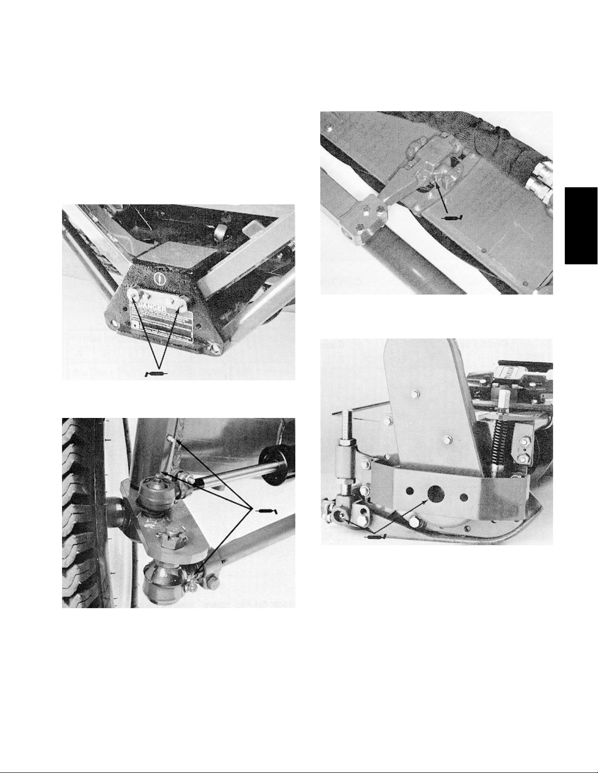
GREASING BEARINGS AND BUSHINGS
The machine has grease fittings that must be lubricated
after every 50 hours of operation with No. 2 General Purpose Lithium Base Grease. Lubricate fitting immediately
after every washing regardless of interval listed. The lubrication points are: lift arms (Fig. 1), rear axle (Fig. 2),
floating or fixed head kit pivots (Fig. 3), and cutting unit
reel and roller bearings (Fig. 4). Also, grease fitting on
reel control valve (not shown), located under right
hand console.
Note: Remove plastic caps over the fittings on the
floating or fixed head pivots and replace caps after
greasing (Fig. 3).
and Manuals
Product Records
Figure 3
Floating of Fixed Kit Pivots (1 fitting per head)
(Floating Kit Shown)
Figure 1
Lift arms (5 fittings total)
Figure 2
Rear Axle (3 Fittings per side)
Figure 4
Reel and Roller Bearings
(2 fittings per reel & 2 fittings per roller)
1. Park machine on a level surface. Stop engine. Remove key from the ignition switch.
2. Wipe grease fitting clean so foreign matter cannot
be forced into the bearing or bushing.
3. Pump grease into the bearing or bushing.
Reelmaster 4000–D
4. Wipe up excess grease.
Page 2 – 7
Product Records and Maintenance
Page 18

Product Records and Maintenance
Page 2 – 8
Reelmaster 4000–D
Page 19

EQUIPMENT OPERATION AND SERVICE HISTORY REPORT
for
REELMASTERR 4000–D
TORO Model and Serial Number: ______________–______________
Engine Numbers: _____________________________
Transmission Numbers: _____________________________
Drive Axle(s) Numbers: _____________________________
Date Purchased: _____________________________ Warranty Expires____________
Purchased From: _____________________________
and Manuals
Product Records
_____________________________
_____________________________
Contacts: Parts _____________________________ Phone____________________
Service _____________________________ Phone____________________
Sales _____________________________ Phone____________________
Reelmaster 4000–D
Page 2 – 9
Product Records and Maintenance
Page 20
Reelmaster 4000–D Maintenance Schedule
Minimum Recommended Maintenance Intervals
Maintenance Procedure
Lubricate Reel Control Valve Grease Fitting
Lubricate Reel Speed Valve with Oil
Lubricate All Grease Fittings
Check Battery Condition and Connections
Change Engine Oil and Filter
Drain Water from Hydraulic Tank
Check Engine Fan and Alternator Belt
Inspect Cooling System Hoses
Inspect Cutting Unit Reel Drive Belts
Torque Wheel Lug Nuts
Service Air Cleaner
Replace Fuel Filters
Inspect Fuel Lines and Connections
Check Engine RPM (idle and full throttle)
Drain and Clean Fuel Tank
Replace Hydraulic Oil Filters
Adjust V alves
Replace Hydraulic Tank Breather
Change Front Planetary Gear Lube
Pack Rear Wheel Bearings
Check Rear Wheel Toe–in
Maintenance Interval & Service
Every
400hrs
D Level
Service
E Level
Service
Every
50hrs
A Level
Service
Every
100hrs
B Level
Service
Every
200hrs
C Level
Service
Every
800hrs
Initial break in at 10 hours
Initial break in at 50 hours
Replace Moving Hydraulic Hoses
Replace Safety Switches
Coolant System – Flush/Replace Fluid
Change Hydraulic Oil
Annual Recommendations:
Items listed are recommended every 1500
hours or 2 years, whichever occurs first.
(See Operator’s and Service Manual for specifications and procedures)
Product Records and Maintenance
Page 2 – 10
Reelmaster 4000–D
Page 21
Reelmaster 4000–D Daily Maintenance Checklist
Daily Maintenance: (duplicate this page for routine use)
Check proper section of Operator’s Manual for fluid specifications
Maintenance
Check Item b
n Safety Interlock Operation
n Parking Brake Operation
n Engine Oil Level
n Fuel Level
n Cooling System Fluid Level
Daily Maintenance Check For Week Of _________________
MON TUES WED THURS FRI SAT SUN
Drain Water/Fuel Separator
n Air Filter Restriction Indicator
n Radiator, Oil Cooler and
Screen for Debris
1
Clean Traction Pedal Lockout
n Unusual Engine Noises
n Unusual Operating Noises
n Hydraulic System Oil Level
n Hydraulic Hoses for Damage
n Fluid Leaks
n Tire Pressure
n Instrument Operation
n Warning Lamps Operation
n Reel–to–Bedknife Adjustment
n Height–of–Cut Adjustment
Lubricate All Grease Fittings
2
3
Touch–up Damaged Paint
1
= Use only low pressure compressed air for debris removal. Do not use water.
2
= Check glow plugs and injector nozzles, if hard starting excess smoke or rough running is noted.
3
= Immediately after every washing, regardless of the interval listed.
and Manuals
Product Records
Notation for areas of concern: Inspection performed by_____________________________
Item Date Information
1
2
3
4
5
6
7
8
Reelmaster 4000–D
Page 2 – 11
Product Records and Maintenance
Page 22
Date: ________________
Inspect Cutting Unit Reel Drive Belts
Torque Wheel Lug Nuts
A and B – Service required
________________________________
________________________________
________________________________
________________________________
________________________________
________________________________
Replace Moving Hydraulic Hoses (2 years)
Replace Safety Switches (2 years)
Flush/Replace Engine Coolant (2 years)
Change Hydraulic Oil (2 years)
________________________________
________________________________
________________________________
________________________________
________________________________
Remarks:
A B C D Other
TORO I.D. #:
__________________–__________________
Service to perform (circle):
Reelmaster 4000–D Supervisor Maintenance Work Order
Unit Designation:
(Duplicate this page for routine use.)
Hours:
Technician:
Change Engine Oil and Filter
Drain Water From Hydraulic Tank
Check Engine Fan and Alternator Belt
Inspect Cooling System Hoses
A – Service required
_______________________________
_______________________________
Lube Reel Control Valve Grease Fittings
Lube Reel Speed Valve with Oil
Lubricate All Grease Fittings
Check Battery Condition and Connectoins
________________________________
________________________________
A– Service (every 50 hours) B – Service (every 100 hours) C – Service (every 200 hours
________________________________
_______________________________
_______________________________
________________________________
________________________________
Drain and Clean Fuel Tank
Replace Hydraulic Oil Filter
Adjust Engine V alves
Replace Hydraulic Tank Breather
Change Front Planetary Gear Lube
Pack Rear Wheel Bearings
Service Air Cleaner
Replace Fuel Filters
Inspect Fuel Lines and Connections
D – Service (every 400 hours) E – Service (every 800 hours) Other – Annual Service and Specials
Check Engine RPM (idle and full throttle)
________________________________
A, B and C – Service required
Check Rear Wheel Toe–in
A, B, C and D – Service required
_______________________________
________________________________
________________________________
________________________________
(See Operator’s and Service Manual for specifications and procedures.)
Product Records and Maintenance
Page 2 – 12
Reelmaster 4000–D
Page 23

Table of Contents
Chapter 3
Kubota Diesel Engine
INTRODUCTION 2. . . . . . . . . . . . . . . . . . . . . . . . . . . . . .
SPECIFICA TIONS 3. . . . . . . . . . . . . . . . . . . . . . . . . . . .
GENERAL INFORMATION 4. . . . . . . . . . . . . . . . . . . . .
Check Engine Oil 4. . . . . . . . . . . . . . . . . . . . . . . . . . .
Check Cooling System 5. . . . . . . . . . . . . . . . . . . . . . .
Fill Fuel Tank 5. . . . . . . . . . . . . . . . . . . . . . . . . . . . . . .
Prime Fuel System 6. . . . . . . . . . . . . . . . . . . . . . . . . .
ADJUSTMENTS 7. . . . . . . . . . . . . . . . . . . . . . . . . . . . . .
Adjust Alternator Belt 7. . . . . . . . . . . . . . . . . . . . . . . .
SERVICE AND REPAIRS 8. . . . . . . . . . . . . . . . . . . . . .
Service Air Cleaner 8. . . . . . . . . . . . . . . . . . . . . . . . . .
Change Engine Oil and Filter 9. . . . . . . . . . . . . . . . .
Drain Fuel System 10. . . . . . . . . . . . . . . . . . . . . . . . .
Check Fuel Lines and Connections 11. . . . . . . . . . . .
Replace Fuel Filters 11. . . . . . . . . . . . . . . . . . . . . . . . .
Engine Cooling System 12. . . . . . . . . . . . . . . . . . . . .
Engine 13. . . . . . . . . . . . . . . . . . . . . . . . . . . . . . . . . . . .
Engine Removal 13. . . . . . . . . . . . . . . . . . . . . . . . . .
Engine Installation 16. . . . . . . . . . . . . . . . . . . . . . . .
KUBOT A WORKSHOP MANUAL, 03 SERIES, DIESEL
ENGINE
Engine
Kubota Diesel
Reelmaster 4000–D Page 3 – 1 Kubota Diesel Engine
Page 24

Introduction
This Chapter gives information about specifications,
maintenance, troubleshooting, testing, and repair of the
diesel engine used in the Reelmaster 4000–D.
Most repairs and adjustments require tools, which are
commonly available in many service shops. Special
tools are described in the Kubota Workshop Manual,
03 Series, Diesel Engine. The use of some specialized
test equipment is explained. However, the cost of the
test equipment and the specialized nature of some repairs may dictate that the work be done at an engine repair facility.
Service and repair parts for Kubota diesel engines are
supplied through your local Kubota dealer or distributor.
If no parts list is available, be sure to provide your distributor with the Toro model and serial number.
Kubota Diesel Engine
Page 3 – 2
Reelmaster 4000–D
Page 25

Specifications
Item Description
Make / Designation Kubota, V2203, 4–Cylinder, 4–Cycle,
Water Cooled, In–line, Spherical Chamber , OHV, Diesel Engine
Horse Power 39.4 HP @ 2300 RPM
Torque 103 ft–lb @ 1600 RPM
Firing Order 1 – 3 – 4 – 2
Bore mm (in.) 87.0 (3.43)
Stroke mm (in.) 92.0 (3.64)
Total Displacement cc (cu. in.) 2197 (134.07)
Fuel No. 2 Diesel Fuel per ASTM D975
Fuel Capacity liters (gallons) 56.8 (15.0)
Fuel Pump Bosch Type Mini pump
Governor Centrifugal flyweight Mechanical Type
Low Idle (no load) 1250 + 50 RPM
High Idle (no load) 2500 + 50 RPM
Engine
Kubota Diesel
Compression Ratio 23.0 : 1
Rotation Counterclockwise Facing Flywheel
Injection Nozzles Bosch Throttle Type
Engine Oil SAE 10W30 SF or CD
Oil Pump Trochoid T ype
Crankcase Oil Capacity liters (U.S. qt.) 7.6 (8.0) with filter
Starter 12 VDC 1.4 KW
Alternator/Regulator 12 VDC 40 AMP
Weight Kg (Lb.) 190 (418)
Engine Coolant Capacity liters (U.S. qt.) 14.0 (14.8)
Timing BTDC 17 to 19 Degrees
Reelmaster 4000–D Page 3 – 3 Kubota Diesel Engine
Page 26
General Information
Check Engine Oil
1. Park machine on a level surface. Stop engine. Remove key from the ignition switch.
2. Release engine cover latches. Open engine cover
(Fig. 1).
3. Remove dipstick, wipe clean and reinstall dipstick
into tube and pull it out again. Oil level should be up to
the FULL mark (Fig. 2).
4. If oil is below FULL mark, remove fill cap and add
SAE 10W–30 oil until level reaches the FULL mark. Do
not overfill. Crankcase capacity is 8 qt. (7.6 L) with filter
(Fig. 3).
5. Install oil fill cap and dipstick.
6. Close engine cover and secure with the latches.
1
Figure 1
1. Engine cover latch
1
Kubota Diesel Engine
Page 3 – 4
Figure 2
1. Dipstick
1
Figure 3
1. Oil fill cap
Reelmaster 4000–D
Page 27
Check Cooling System
Check level of coolant at the beginning of each day . Capacity of system is 3.7 gal. (14 L).
CAUTION
If engine is hot, pressurized coolant can escape
and cause burns when the radiator cap is removed. Remove radiator cap slowly and carefully if engine coolant is hot.
1. Park machine on a level surface. Stop engine. Remove key from the ignition switch.
2. Carefully remove radiator cap (Fig. 4) and expansion tank cap (Fig. 5).
3. Check level of coolant in radiator. Radiator should
be filled to the top of the filler neck and the expansion
tank filled to the marks on its side.
IMPORTANT: Do not use water only. Do not use alcohol / methanol base coolants.
1
Figure 4
1. Radiator cap 2. Rear screen
1
2
Engine
Kubota Diesel
4. If coolant is low, add a 50/50 mixture of water and
ethylene glycol anti–freeze.
5. Install radiator cap and expansion tank cap.
Fill Fuel Tank
1. Park machine on a level surface. Stop engine. Remove key from the ignition switch.
2. Remove fuel tank cap (Fig. 6).
3. Fill tank to about one inch (25 mm) below bottom of
filler neck with No. 2 diesel fuel. Then install cap.
Figure 5
1. Expansion tank cap
1
2
Figure 6
1. Fuel tank cap 2. Left rear tire
Reelmaster 4000–D Page 3 – 5 Kubota Diesel Engine
Page 28
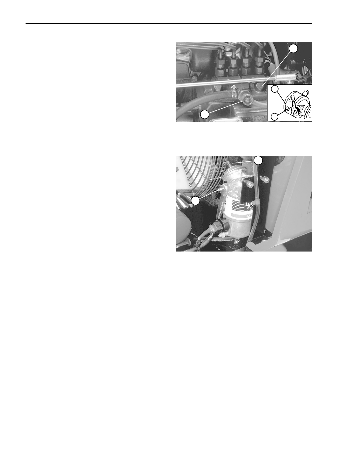
Prime Fuel System
IMPORT ANT : The fuel system must be primed when
a new engine is started for the first time, if it runs out
of fuel, or if maintenance is performed on the fuel
system.
Note: The fuel pump, located on left side of engine,
under the fuel injection pump and behind the fuel stop
solenoid. It can be manually primed to get fuel from fuel
tank to fuel filter/water separator (Fig. 7).
1. Park machine on a level surface. Stop engine. Remove key from the ignition switch.
2. Raise engine cover.
3. Insert a 3/16–inch hose over the bleed screw, and
run the other end of the hose into a container to catch the
fuel (Fig. 8).
IMPORTANT: Priming fuel filter without opening
bleed screw may damage priming plunger.
4. Loosen fuel filter/water separator bleed screw a few
turns. Pump priming plunger until a steady stream of fuel
comes out of hole in in bleed screw. When fuel stops
foaming, tighten the bleed screw during the down-
stroke of the priming plunger. Wipe up any spilled fuel
(Fig. 8).
1
1. Bleed knob
2. Injection pump
2
2
3
4
Figure 7
3. Fuel pump
4. Priming lever
1
Note: It may be necessary to bleed the air out of the
fuel line between the fuel filter / water separator and the
injection pump. T o do this, loosen the knob on the injection pump (Fig. 7) and repeat bleeding procedure.
5. Pump priming plunger until resistance is felt. Try to
start engine. If engine does not start repeat step 4.
1. Primer plunger 2. Bleed screw
Figure 8
Kubota Diesel Engine
Page 3 – 6
Reelmaster 4000–D
Page 29
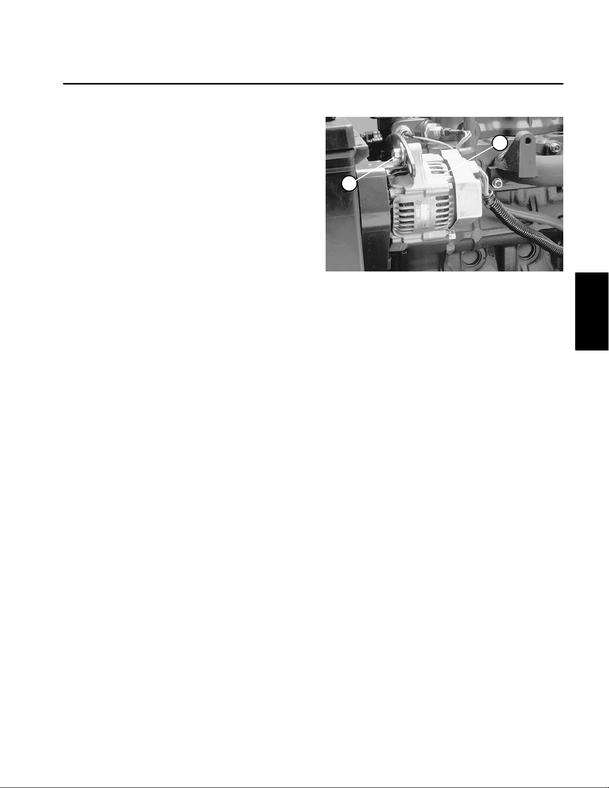
Adjustments
Adjust Alternator Belt
Check condition and tension of belt after every 100 operating hours (Fig. 9).
1. Park machine on a level surface. Stop engine. Remove key from the ignition switch.
1
2. Proper belt tension will allow 3/8 inch (10 mm)
deflection when a force of 10 lbs (44.4 N) is applied on
the belt midway between both pulleys.
3. If deflection is not 3/8 inch (10 mm), loosen alternator mounting bolt. Increase or decrease alternator belt
tension and tighten bolt. Make sure tension is correct;
check deflection of belt again.
2
Figure 9
1. Alternator 2. Mounting bolt
Engine
Kubota Diesel
Reelmaster 4000–D Page 3 – 7 Kubota Diesel Engine
Page 30
Service and Repairs
Service Air Cleaner
1. Park machine on a level surface. Stop engine. Remove key from the ignition switch.
2. Remove knobs securing rear screen to frame . Remove rear screen (Fig. 10).
3. Check air cleaner body for damage which could
possibly cause an air leak. Replace a damaged air
cleaner body (Fig. 11).
4. Service the air cleaner filters when ever air cleaner
indicator light illuminates and warning signal sounds or
every 400 hours (more frequently in extreme dusty or
dirty conditions). Do not over service air filter.
5. Be sure cover is sealing around air cleaner body
(Fig. 11).
6. Release latches securing air cleaner cover to air
cleaner body . Separate cover from body. Clean inside of
air cleaner cover (Fig. 11).
7. Gently slide primary filter out of air cleaner body to
reduce the amount of dust dislodged. Avoid knocking filter against air cleaner body . Do not remove safety fil-
ter.
IMPORTANT: Never attempt to clean a safety filter
(Located inside primary filter). Replace the safety
filter with a new one after every three primary filter
services.
8. Inspect primary filter and discard if damaged. Do not
wash or reuse a damaged filter.
Washing Method
A. Prepare a solution of filter cleaner and water a
nd soak filter element about 15 minutes. Refer to
directions on filter cleaner carton for complete information.
B. After soaking filter for 15 minutes, rinse it with
clear water. Maximum water pressure must not exceed 40 psi to prevent damage to the filter element.
Rinse filter from clean side to dirty to side.
C. Dry filter element using warm, flowing air of not
greater than 160oF (71oC), or allow element to air–
dry. Do not use a light bulb to dry the filter element
because damage could result.
2
1
Figure 10
1. Rear screen 2. Knob
2
1
Figure 11
1. Air cleaner body 2. Air cleaner cover
Compressed Air Method
A. Blow compressed air from inside to the outside
of dry filter element. Do not exceed 100 psi (6.9 Bar)
to prevent damage to the element.
B. Keep air hose nozzle at least 2 inches (5 cm)
from filter and move nozzle up and down while rotating the filter element. Inspect for holes and tears by
looking through the filter toward a bright light.
9. Inspect new filter for shipping damage. Check sealing end of filter. Do not install a damaged filter.
10. Insert new filter properly into air cleaner body . Make
sure filter is sealed properly by applying pressure to outer rim of filter when installing. Do not press on flexible
center of filter.
Kubota Diesel Engine
1 1. Reinstall cover and secure latches. Make sure cover is positioned with top side up.
Page 3 – 8
Reelmaster 4000–D
Page 31

Change Engine Oil and Filter
Change oil and filter after the first 50 hours of operation
and every 100 hours thereafter.
1. Remove drain plug and let oil flow into drain pan.
When oil stops, install drain plug (Fig. 12).
2. Remove oil filter. Apply a light coat of clean oil to the
new filter seal before screwing it on. Do not overtighten
filter (Fig.13).
3. Add oil to crankcase (see Check Engine Oil).
1
2
Figure 12
1. Drain plug 2. Starter
Engine
Kubota Diesel
1
2
Figure 13
1. Oil filter 2. Fuel filter/water seperator
Reelmaster 4000–D Page 3 – 9 Kubota Diesel Engine
Page 32

Drain Fuel System
3
DANGER
Because diesel fuel is highly flammable, use caution when storing or handling it. Do not smoke
while filling the fuel tank. Do not fill fuel tank
while engine is running, hot, or when machine is
in an enclosed area. Always fill fuel tank outside
and wipe up any spilled diesel fuel before starting the engine. Store fuel in a clean, safety–approved container and keep cap in place. Use diesel fuel for the engine only; not for any other
purpose
Fuel Tank
Drain and clean fuel tank every 800 hours of operation
or yearly, whichever comes first. Also, drain and clean
tank if fuel system becomes contaminated or if machine
is to be stored for an extended period. Use clean fuel to
flush out the tank.
Fuel Filter/Water Separator
Drain water or other contaminants from fuel filter/water
separator daily.
1. Park machine on a level surface. Stop engine. Remove key from the ignition switch.
1
Figure 14
1. Fuel filter/water separator
2. Drain screw
2
3. Priming plunger
2. Place a clean container under the fuel filter.
3. Loosen drain thumb screw on the side of fuel filter.
Press primer plunger until only fuel is evident draining
into container.
4. Tighten drain screw.
Kubota Diesel Engine
Page 3 – 10
Reelmaster 4000–D
Page 33

Check Fuel Lines and Connections
Check lines and connections every 400 hours or yearly ,
whichever comes first. Inspect for deterioration, damage, or loose connections.
Replace Fuel Filter
DANGER
Because diesel fuel is highly flammable, use caution when storing or handling it. Do not smoke
while filling the fuel tank. Do not fill fuel tank
while engine is running, hot, or when machine is
in an enclosed area. Always fill fuel tank outside
and wipe up any spilled diesel fuel before starting the engine. Store fuel in a clean, safety–approved container and keep cap in place. Use diesel fuel for the engine only; not for any other
purpose
There are 2 fuel filters on the RM 4000–D. A small in–
line filter is located on top of the fuel tank and behind the
the radiator (Fig. 15). The fuel filter/water seperator is located near the left rear end of the engine (Fig. 16).
Replace fuel filters if fuel flow becomes restricted, after
every 400 hours of operation or annually, whichever
comes first.
1. Park machine on a level surface. Stop engine. Remove key from the ignition switch.
2. Unscrew bottom filter cap from filter assembly . Remove cap, gaskets, o-ring and filter from assembly . Note
position of gaskets and o-ring when disassembling from
filter.
1
Figure 15
1. In–line fuel filter 2. Fuel tank
1
3
2
2
Engine
Kubota Diesel
3. Install new filter, gaskets, o-ring with filter assembly
cap.
Figure 16
4. Prime fuel system, refer to Priming Fuel System.
Reelmaster 4000–D Page 3 – 11 Kubota Diesel Engine
1. Fuel filter/water separator
2. Filter cap
3. Filter
Page 34

Engine Cooling System
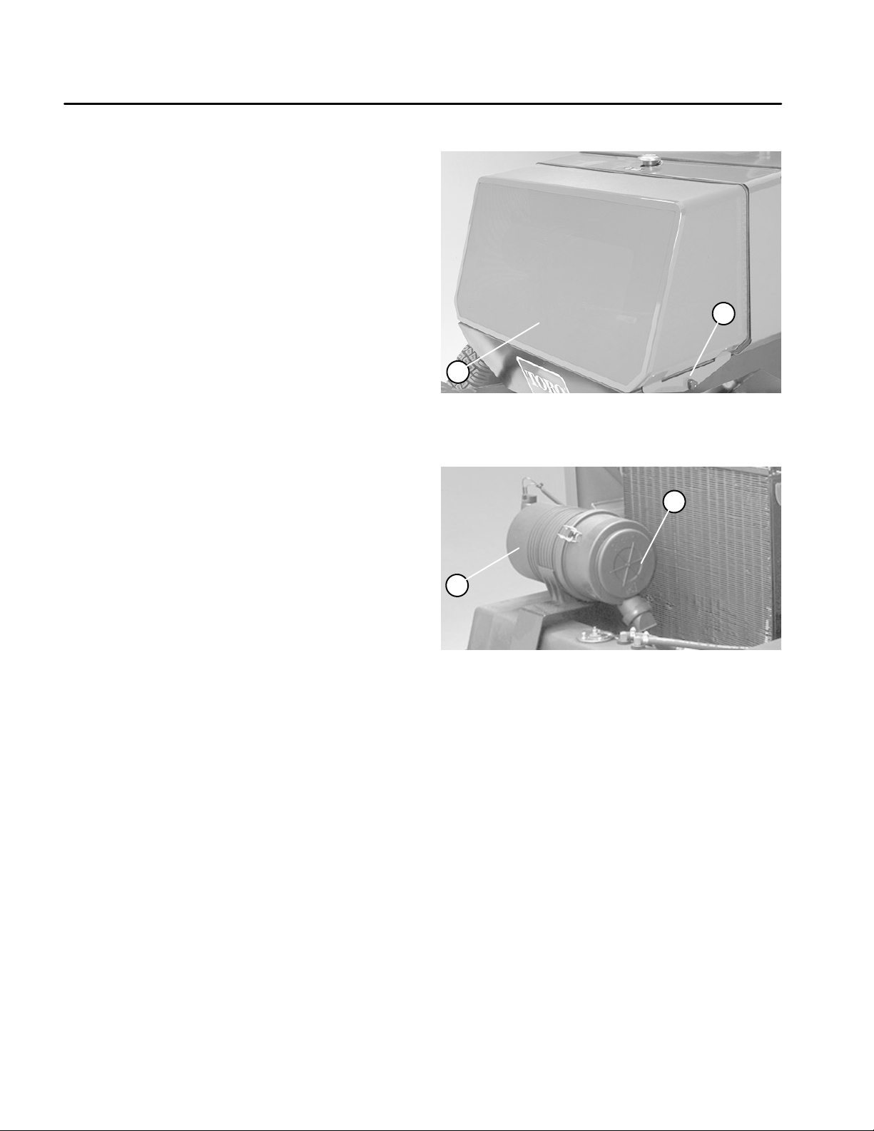
Debris Removal
Remove debris from oil cooler, radiator and rear screen
daily, clean more frequently in dirty conditions.
1. Park machine on a level surface. Stop engine. Remove key from the ignition switch.
2. Release front engine cover latches and raise engine
cover. Clean engine area thoroughly of all debris.
3. Remove knobs securing rear screen to frame and
remove screen (Fig. 17).
4. Lift up on oil cooler handles and pivot rearward in
mounting slot. Clean both sides of oil cooler, radiator
and rear engine area thoroughly with compressed air
(Fig. 18).
5. Pivot oil cooler back into position and install rear
screen.
2
1
Figure 17
1. Rear screen 2. Knob
6. Lower engine cover and secure latches.
Cooling System Maintenance
Capacity of the system is 3.7 gal. (14 L). Always protect
cooling system with a 50/50 solution of water and ethylene glycol anti–freeze.
IMPORTANT: Do not use water only. Do not use alcohol / methanol base coolants.
1. Park machine on a level surface. Stop engine. Remove key from the ignition switch.
2. After every 100 operating hours, tighten hose connections. Replace any damaged of deteriorated hoses.
3. After every 800 ooperating hours, drain and flush
the cooling system. Add anti–freeze (see Check Cooling
System).
2
1
Figure 18
1. Oil cooler 2. Radiator
Kubota Diesel Engine
Page 3 – 12
Reelmaster 4000–D
Page 35

Engine
Engine Removal
1. Park machine on a level surface, lower cutting units,
stop engine, engage parking brake, and remove key
from the ignition switch.
2. Pivot seat up. Lift front canopy and remove from the
brackets (Fig. 19).
3. Disconnect and remove battery from the machine
(see Battery Service in Chapter 5 – Electrical Systems).
CAUTION
If engine is hot, pressurized coolant can escape
and cause burns when the radiator hoses are removed. The radiator and exhaust exhaust tube
may be hot. Avoid possible burns; allow engine,
radiator, and exhaust system to cool before removing radiator hoses or exhaust tube.
4. Drain radiator. Disconnect both hoses from the radiator (Fig. 20).
5. Remove air hose from air intake manifold (Fig. 20).
6. Remove exhaust shield from the engine (Fig. 20).
1
2
Figure 19
1. Canopy 2. Brackets
5
11
2
4
6
12
9
1
3
Figure 20
1. Battery
2. Upper radiator hose
3. Lower radiator hose
4. Fan guard
5. Fan shroud
6. Exhaust shield
7. Starter
8. OIl pressure switch
9. Alternator
10. Air hose
11. Hi temp. warning switch
12. Hi temp. cutout switch
10
Engine
Kubota Diesel
8
7
7. Remove fan guard and fan shroud from the radiator
(Fig. 20).
1
8. Remove fan from the fan pulley . Remove fan shroud
and fan from machine (Fig. 21). Remove fan shroud
from the machine.
2
3
Figure 21
1. Fan
2. Fan pulley
3. Cap screws
Reelmaster 4000–D Page 3 – 13 Kubota Diesel Engine
Page 36

9. Clamp to prevent drainage, and disconnect the following fuel hoses:
A. Suction hose at the injector pump from the fuel
filter. Suction and discharge hoses at the fuel pump
(Fig. 22).
B. Return hose from the fuel injectors (Fig. 23).
1
4
10. Disconnect wire harness and electrical wires from
the engine as follows:
A. Disconnect wire and connector from the alternator, red cable from starter , three wires from the starter, wire from the oil pressure switch, and wires from
high temperature warning and shutdown switches
(Fig. 20).
B. Disconnect electrical connector from the fuel solenoid (Fig. 22).
C. Disconnect red/black wire from the glow plug
bus bar (Fig. 23).
3
1. Injector pump suction
2. Fuel pump suction
2
5
1. Injector return hose
2. Glow plug wire
3. Exhaust tube
2
Figure 22
3. Fuel pump discharge
4. Fuel solenoid
1
Figure 23
4. Bracket
5. Lift tab
1 1. Disconnect throttle control cable from the swivel lever and R–clamp from the engine plate (Fig. 24).
Kubota Diesel Engine
Page 3 – 14
1
3
4
1. Throttle control cable
2. R–clamp
3. Swivel
Figure 24
4. Swivel lever
5. Engine plate
6. Screw
2
2
6
3
4
5
Reelmaster 4000–D
Page 37

12. Separate hydraulic pump assembly from the engine
(Fig. 25).
A. Disconnect damper from the bracket.
B. Remove four cap screws, lock washers, and flat
washers securing the pump mounting flange to the
pump adapter plate.
C. Support pump, and pull pump shaft from the
spring coupling.
4
2
Figure 25
1. Damper
2. Bracket
3. Pump mounting flange
1
5
4. Pump adapter plate
5. Spring coupling
3
4
13. Remove three lock nuts and cap screws securing
the upper exhaust tube to the exhaust bracket (Fig. 26).
14. Remove hex nut, spring washer, cap screw , and flat
washers securing both front brackets to the engine
mounts (Fig. 26).
15. Connect hoist or lift to the engine.
CAUTION
Make sure lift or hoist can support the total
weight of the engine before removing the cap
screws from the rear bracket and engine.
16. Remove three cap screws and lock washers securing the engine to the rear bracket and spacer (Fig. 27).
CAUTION
One person should operate lift or hoist while the
other person guides the engine out of the machine.
9
4
5
10
8
6
7
1. Cap screw
2. Upper exhaust tube
3. Exhaust bracket
4. Hex nut
5. Spring washer
1
2
9
Figure 26
6. Cap screw
7. Flat washer
8. Flat washer
9. Front bracket
10. Engine mount
3
Engine
Kubota Diesel
1
IMPORTANT: Make sure not to damage the engine,
fuel and hydraulic lines, electrical harness, or other
parts while removing the engine.
17. Remove engine slowly from the machine. Save gas-
2
1
ket for exhaust tube (Fig. 26).
Figure 27
1. Rear bracket & spacer 2. Cap screw & lock washer
Reelmaster 4000–D Page 3 – 15 Kubota Diesel Engine
Page 38

Engine Installation
C. Connect red/black wire to the glow plug bus bar
(Fig. 23).
CAUTION
One person should operate lift or hoist while the
other person guides the engine into the frame.
1. Install engine to the front engine mounts and rear
brackets.
A. Attach a hoist or lift to the engine.
IMPORTANT: Make sure not to damage the engine,
fuel and hydraulic lines, electrical harness, or other
parts while installing the engine.
B. Place gasket onto exhaust bracket to receive exhaust tube (Fig. 26).
C. Lower engine slowly into the machine.
2. Secure both front brackets to the engine mounts
with cap screw, flat washers, spring washer , and hex nu.
T orque cap screw and hex nut from 59 to 73 ft–lb (8.2 to
10.1 kg–m)t (Fig. 26).
3. Secure engine to the spacers and rear brackets with
three cap screws and lock washers. T orque cap screws
from 61 to 75 ft–lb (8.4 to 10.4 kg–m) (Fig. 27).
8. Connect the following fuel hoses:
A. Suction hose at the injector pump from the fuel
filter. Suction and discharge hoses at the fuel pump
(Fig. 22).
B. Return hose from the fuel injectors (Fig. 23).
C. Remove clamps used to prevent drainage.
9. Position fan shroud to the radiator. Install fan to the
fan pulley (Fig. 21).
A. Apply Loctite (Blue) 242 or equivalent to the
ends of the cap screws.
B. Torque cap screws from 80 to 110 in–lb (92 to
127 kg–cm).
10. Install fan shroud and guard to the radiator (Fig. 20).
11. Install exhaust shield to the engine (Fig. 20).
12. Install air hose to air intake manifold (Fig. 20).
13. Install battery the machine and connect cables (see
Battery Service in Chapter 5 – Electrical Systems).
14. Connect both hoses to the radiator (Fig. 20).
4. Secure exhaust tube and gasket to the exhaust
bracket with three cap screws and lock nuts (Fig. 26).
5. Connect hydraulic pump assembly to the engine
(Fig. 25).
A. Position the pump shaft into the spring coupling.
B. Secure pump mounting flange to the pump
adapter plate with four cap screws, flat washers,
and lock washers. T orque cap screws from 60 to 80
ft–lb (8.3 to 11.1 kg–m).
C. Connect damper to the bracket.
6. Connect throttle control cable to the swivel lever.
Secure cable to engine plate with R–clamp (Fig. 24).
7. Connect wire harness and electrical wires to the engine as follows:
A. Connect wire and connector to the alternator,
red cable to starter, three wires to the starter , wire to
the oil pressure switch, and wires to high temperature warning and shutdown switches (Fig. 20).
15. Secure canopy to the brackets (Fig. 19).
16. Fill radiator with coolant (see Check Cooling Sys-
tem).
17. Adjust control cable throttle cable (Fig. 24).
A. Push throttle lever to the FAST position.
B. Loosen screw on swivel that secures the cable to
the swivel lever.
C. Adjust position of swivel lever with cable so the
injector pump lever is contacting the stop in the full
throttle position.
D. Secure cable to swivel with screw.
18. Prime fuel system (see Prime Fuel System).
19. Check traction pedal adjustment for NEUTRAL.
B. Connect electrical connector to the fuel solenoid
(Fig. 22).
Kubota Diesel Engine
Page 3 – 16
Reelmaster 4000–D
Page 39

Table of Contents
Chapter 4
Hydraulic System
SPECIFICATIONS 2. . . . . . . . . . . . . . . . . . . . . . . . . . . .
GENERAL INFORMATION 3. . . . . . . . . . . . . . . . . . . . .
Hydraulic Hoses 3. . . . . . . . . . . . . . . . . . . . . . . . . . . . .
Hydraulic Fitting Installation 3. . . . . . . . . . . . . . . . . . .
Pushing or Towing Traction Unit 5. . . . . . . . . . . . . . .
Check Hydraulic System Fluid 7. . . . . . . . . . . . . . . . .
HYDRAULIC SCHEMATIC 8. . . . . . . . . . . . . . . . . . . . .
HYDRAULIC FLOW DIAGRAMS 9. . . . . . . . . . . . . . . .
General Pump Flow 9. . . . . . . . . . . . . . . . . . . . . . . . . .
Engine Run – No Functions 10. . . . . . . . . . . . . . . . . .
Traction Circuit 11. . . . . . . . . . . . . . . . . . . . . . . . . . . . . .
Traction Circuit – Forward 12. . . . . . . . . . . . . . . . . . .
Steering Circuit 13. . . . . . . . . . . . . . . . . . . . . . . . . . . . .
Steering Right 14. . . . . . . . . . . . . . . . . . . . . . . . . . . . . .
Lift/Lower Circuit 15. . . . . . . . . . . . . . . . . . . . . . . . . . .
Lift Circuit – Lift All Units 16. . . . . . . . . . . . . . . . . . . . .
Lift Circuit – Lower All Units 17. . . . . . . . . . . . . . . . . .
Lift Circuits – Free Float (Detent) 18. . . . . . . . . . . . .
Reel Circuit 19. . . . . . . . . . . . . . . . . . . . . . . . . . . . . . . .
Reel Circuit – All Units Mow (Free Float) 20. . . . . . .
Reel Circuit – Units 1, 2 & 3 Mow (Free Float) 21. .
Reel Circuit – Units 1, 2, 3 & 5 (Free Float) 22. . . .
Reel Circuit – Any Unit Backlap 23. . . . . . . . . . . . . .
4WD SELECTOR VALVE OPERATION 24. . . . . . . . .
4WD Forward 24. . . . . . . . . . . . . . . . . . . . . . . . . . . . . .
2WD Forward 25. . . . . . . . . . . . . . . . . . . . . . . . . . . . . .
SPECIAL TOOLS 26. . . . . . . . . . . . . . . . . . . . . . . . . . . .
Hydraulic Tester with Pressure and Flow
Capabilities 26. . . . . . . . . . . . . . . . . . . . . . . . . . . . . . .
Hydraulic Pressure Test Kit 27. . . . . . . . . . . . . . . . . .
Hydraulic Fitting Kit 27. . . . . . . . . . . . . . . . . . . . . . . . .
TROUBLESHOOTING 28. . . . . . . . . . . . . . . . . . . . . . . .
Hydraulic Oil Leak(s) 28. . . . . . . . . . . . . . . . . . . . . . . .
Slow or No Traction in Either Direction 28. . . . . . . .
Reels Slow or Won’t Turn 28. . . . . . . . . . . . . . . . . . . .
Steering Loss 29. . . . . . . . . . . . . . . . . . . . . . . . . . . . . .
Cutting Units Lift Slow or Won’t Lift 29. . . . . . . . . . .
Cutting Units Won’t Drop
or Follow Ground Contours 29. . . . . . . . . . . . . . . . .
TESTING 30. . . . . . . . . . . . . . . . . . . . . . . . . . . . . . . . . . .
Precautions for Hydraulic Testing 30. . . . . . . . . . . . .
Test No. 1: Check Traction Working
and Relief Pressures 31. . . . . . . . . . . . . . . . . . . . . . .
Test No. 2: Check Counterbalance
Oil Pressure 32. . . . . . . . . . . . . . . . . . . . . . . . . . . . . .
Test No. 3: Check Reel Circuit Working
and Relief Pressures 33. . . . . . . . . . . . . . . . . . . . . . .
Test No. 4: Check Reel Circuit Flow 34. . . . . . . . . . .
Test No. 5: Check Reel Motor Cross–Over
Relief Pressure 35. . . . . . . . . . . . . . . . . . . . . . . . . . .
Test No. 6: Check Reel Motor Case Drain Flow 36.
Test No. 7: Check Steering Circuit Working
and Relief Pressures 37. . . . . . . . . . . . . . . . . . . . . . .
Test No. 8: Check Lift Circuit Working
and Relief Pressures 38. . . . . . . . . . . . . . . . . . . . . . .
Test No. 9: Check Charge Pressure 38. . . . . . . . . . .
SERVICE AND REPAIRS 39. . . . . . . . . . . . . . . . . . . . .
Removing Hydraulic System Components 39. . . . .
Steering Control Unit 40. . . . . . . . . . . . . . . . . . . . . . . .
Add Hydraulic Fluid 51. . . . . . . . . . . . . . . . . . . . . . . . .
Drain Water from Hydraulic Reservoir 51. . . . . . . . .
Reel Motor 52. . . . . . . . . . . . . . . . . . . . . . . . . . . . . . . .
Steering Pump 54. . . . . . . . . . . . . . . . . . . . . . . . . . . . .
Lift Control Valve 58. . . . . . . . . . . . . . . . . . . . . . . . . . .
Priority Flow Divider 60. . . . . . . . . . . . . . . . . . . . . . . .
Lift Cylinder 62. . . . . . . . . . . . . . . . . . . . . . . . . . . . . . . .
Reel Control Valve 64. . . . . . . . . . . . . . . . . . . . . . . . . .
Reel Shut Off Valve 66. . . . . . . . . . . . . . . . . . . . . . . . .
Traction Pump 68. . . . . . . . . . . . . . . . . . . . . . . . . . . . .
Front Traction Motor 74. . . . . . . . . . . . . . . . . . . . . . . .
Reel Pump 76. . . . . . . . . . . . . . . . . . . . . . . . . . . . . . . .
Rear Wheel Drive Motor 80. . . . . . . . . . . . . . . . . . . . .
Rear Wheel Drive Valve Block 87. . . . . . . . . . . . . . . .
Steering Cylinder 88. . . . . . . . . . . . . . . . . . . . . . . . . . .
Change Hydraulic Oil 90. . . . . . . . . . . . . . . . . . . . . . .
Replace Hydraulic Oil Filter 91. . . . . . . . . . . . . . . . . .
Replace Hydraulic System Breather 91. . . . . . . . . . .
Replace Hydraulic Lines and Hoses 91. . . . . . . . . . .
System
Hydraulic
Reelmaster 4000–D
Page 4 – 1
Hydraulic System
Page 40

Specifications
Item Description
Traction Pump Variable displacement axial piston pump
Traction Relief Pressure 5000 – 5200 PSI
Charge Pressure 50 – 150 PSI (2WD) 75 – 150 PSI (4WD)
Steering Pump Gear pump with flow divider
Steering Relief Pressure 1200 – 1300 PSI
Traction Motor (front) Fixed axial piston motor
Traction Motor (rear w/4WD) Geroter type wheel motors
Reel Pump Gear pump
Cutting Circuit Relief Pressure 2650 – 2750 PSI
Reel Motor Gear Motor
Cross–over Relief Pressure 1500 PSI
Lift Control Valve Spool type directional control valve
Lift Relief Pressure 2650 – 2900 PSI
Counterbalance Pressure (Max. RPM) Hot oil 500 – 550 PSI, cold oil 600 – 650 PSI
Hydraulic Filter (Fig. 1) Spin–on cartridge type
Hydraulic Oil Mobil DTE 26/Shell Tellus 68 or equivalent (see Add Hydraulic Fluid)
Reservoir (Fig. 2) Reservoir capacity 15 gal. U.S.
System capacity approximately 18.2 gal. U.S.
Hydraulic System
Page 4 – 2
Reelmaster 4000–D
Page 41

General Information
Hydraulic Hoses
Hydraulic hoses are subject to extreme conditions such
as, pressure differentials during operation and exposure
to weather, sun, chemicals, very warm storage conditions or mishandling during operation or maintenance.
These conditions can cause damage or premature deterioration. Some hoses are more susceptible to these
conditions than others. Inspect the hoses frequently for
signs of deterioration or damage.
When replacing a hydraulic hose, be sure that the hose
is straight (not twisted) before tightening the fittings.
This can be done by observing the imprint on the hose.
Use two wrenches; one to hold the hose straight and one
to tighten the hose swivel nut onto the fitting.
WARNING
Before disconnecting or performing any work
on hydraulic system, all pressure in system
must be relieved by stopping the engine and
lowering or supporting the box and/or other attachment.
Keep body and hands away from pin hole leaks
or nozzles that eject hydraulic fluid under high
pressure. Use paper or cardboard, not hands,
to search for leaks. Hydraulic fluid escaping
under pressure can have sufficient force to
penetrate the skin and do serious damage. If
fluid is injected into the skin, it must be surgically removed within a few hours by a doctor
familiar with this type of injury or gangrene
may result.
Hydraulic Fitting Installation
O–Ring Face Seal
1. Make sure both threads and sealing surfaces are free
of burrs, nicks, scratches, or any foreign material.
2. Make sure the O–ring is installed and properly seated
in the groove. It is recommended that the O–ring be replaced any time the connection is opened.
3. Lubricate the O–ring with a light coating of oil.
4. Put the tube and nut squarely into position on the face
seal end of the fitting and tighten the nut until finger tight.
5. Mark the nut and fitting body. Hold the body with a
wrench. Use another wrench to tighten the nut to the correct flats from finger tight (F .F.F .T.). The markings on the
nut and fitting body will verify that the connection has
been tightened.
Size F.F.F.T.
4 (1/4 in. nominal hose or tubing) .75 + .25
6 (3/8 in.) .75 +
8 (1/2 in.) .75 +
10 (5/8 in.) 1.00 +
12 (3/4 in.) .75 +
16 (1 in.) .75 +
.25
.25
.25
.25
.25
Nut
Sleeve
Seal
Body
Figure 1
Final
Position
Mark Nut
and Body
Extend Line
Initial
Position
Finger Tight After Proper Tightening
System
Hydraulic
Reelmaster 4000–D
Page 4 – 3
Figure 2
Hydraulic System
Page 42

SAE Straight Thread O–Ring Port – Non–adjustable
1. Make sure both threads and sealing surfaces are free
of burrs, nicks, scratches, or any foreign material.
2. Always replace the O–ring seal when this type of fitting shows signs of leakage.
3. Lubricate the O–ring with a light coating of oil.
4. Install the fitting into the port and tighten it down full
length until finger tight.
5. Tighten the fitting to the correct flats from finger tight
(F.F.F.T.).
Size F.F.F.T.
O–Ring
Figure 3
4 (1/4 in. nominal hose or tubing) 1.00 +
6 (3/8 in.) 1.50 +
8 (1/2 in.) 1.50 +
10 (5/8 in.) 1.50 +
12 (3/4 in.) 1.50 +
16 (1 in.) 1.50 +
.25
.25
.25
.25
.25
.25
SAE Straight Thread O–Ring Port – Adjustable
1. Make sure both threads and sealing surfaces are free
of burrs, nicks, scratches, or any foreign material.
2. Always replace the O–ring seal when this type of fitting shows signs of leakage.
3. Lubricate the O–ring with a light coating of oil.
4. Turn back the jam nut as far as possible. Make sure
the back up washer is not loose and is pushed up as far
as possible (Step 1).
5. Install the fitting into the port and tighten finger tight
until the washer contacts the face of the port (Step 2).
6. To put the fitting in the desired position, unscrew it by
the required amount, but no more than one full turn
(Step 3).
Lock Nut
Back–up Washer
O–Ring
Figure 4
Step 3Step 1
7. Hold the fitting in the desired position with a wrench
and turn the jam nut with another wrench to the correct
flats from finger tight (F.F.F.T.) (Step 4).
Size F.F.F.T.
4 (1/4 in. nominal hose or tubing) 1.00 + .25
6 (3/8 in.) 1.50 +
8 (1/2 in.) 1.50 +
10 (5/8 in.) 1.50 +
12 (3/4 in.) 1.50 +
16 (1 in.) 1.50 +
Hydraulic System
25
.25
.25
.25
.25
Page 4 – 4
Step 2 Step 4
Figure 5
Reelmaster 4000–D
Page 43

Pushing or Towing Traction Unit
Using Traction Pump By–Pass Valve
In an emergency, the traction unit can be pushed or
towed for a very short distance by using the traction
pump by–pass valve.
IMPORTANT: Do not push or tow the traction unit
faster that 2 to 3 MPH (3 to 5 Km/Hr) because the hydraulic system may be damaged. If traction unit
must be moved a considerable distance, transport
it on a truck or trailer.
2
1. Remove the retainer clip from seat lock rod.
2. Raise seat and support it in upright position with seat
support rod (Fig. 6).
2
1
Figure 6
1. Seat 2. Support rod
3. Lift and remove front panel (Fig. 7).
1
Figure 8
1. Traction pump 2. By–pass valve
IMPORT ANT : Make sure that hand brake is engaged
before opening the by–pass valve.
5. Before starting engine, close by–pass valve. Do not
start engine when valve is open.
IMPORTANT: Running the machine with the by–
pass valve open will cause the hydraulic system to
overheat.
DANGER
Vehicle will roll with front wheel motors disengaged. Vehicle must be on level surface or
wheels must be blocked. There is no effective
braking with wheel motors disengaged.
System
Hydraulic
1
Figure 7
1. Front panel
4. Rotate by–pass valve 90 degrees. Opening the valve
opens an internal passage in the traction pump, thereby
by–passing hydraulic oil. Because oil is by–passed,
traction unit can be moved without damaging the hydraulic system (Fig. 8).
Reelmaster 4000–D
Page 4 – 5
If towing, with front wheel motors disengaged,
Tow Bar Assembly, Toro part no. 58–7020, must
be used.
Hydraulic System
Page 44

Disengaging Planetary Wheel Drives
In an emergency, the Reelmaster 4500–D can be
moved by unlocking the front wheel hubs and towing the
machine.
3. Install disengage covers so dimple on cover is facing
in towards hub. Wheel hubs are now unlocked. (Fig. 10).
DANGER
Vehicle will roll with front wheel motors disengaged. Vehicle must be on level surface or wheels
must be blocked. There is no effective braking
with wheel motors disengaged.
If towing with front wheel motors disengaged,
Tow Bar Assembly, Toro part no. 58–7020, must
be used.
NOTE: The machine can also be moved slowly a short
distance by opening the by-pass valve on the variable
displacement hydraulic pump and pushing or towing the
machine (See Pushing or Towing in the General Information section of Chapter 4 – Hydraulic System).
1. Block the wheels or connect the machine to a towing
vehicle with a rigid towing device.
2. Remove bolts securing disengage covers to both
front wheel hubs (Fig. 9).
2
Figure 10
1. Disengage cover – engaged (dimple facing out)
4. Lock the wheel hubs immediately after towing is completed. Remove disengage covers and reinstall so dimple on cover is facing away from hub.
CAUTION
Do not remove wheel blocks or towing devices
until wheel hubs are securely locked.
Hydraulic System
Figure 9
Page 4 – 6
Reelmaster 4000–D
Page 45

Check Hydraulic System Fluid
1. Look into sight glass (Fig. 11). Oil level should be
even with arrows when checking warm oil. Oil will be 1/4
to 1/2 inch below arrows when cold.
2. If oil level is low, add hydraulic oil to the reservoir
(see Add Hydraulic Fluid).
2
1
1. Hydraulic reservoir 2. Sight glass
Figure 11
System
Hydraulic
Reelmaster 4000–D
Page 4 – 7
Hydraulic System
Page 46

Hydraulic Schematic
REEL MOTORS
LIFT VALVE
2100 100 PSI
P
B
ON-OFF
IN
B
(TYP) IN
(REV)
A
PRIORITY
OUT
A
B
3000
T
RETURN
A
INLET
(FWD)
FILTER
OIL LEVEL
SENSOR
LO-SPEED
PSI
PUMP
PACKAGE
BACKLAP
BA
OIL
COOLER
2500 HI–IDLE
1100 LO–IDLE
REEL SHUT-OFF
CIRCUIT
TEST PORT
CUTTING
LIFT
CYLINDERS
5
3
1
2
4
T
A
B
C
T
E
D
F
REELS
G
COUNTERBALANCE
350 25 PSI
REEL
SPEED
T
TEST PORT
CHARGE
PRESSURE
5000 + 100 –0 PSI
Hydraulic System
STEER
CYLINDER
1200 +100
–0 PSI
SHUT–
DOWN
WARNING
TEST PORT
LIFT CYLS
R
TRACTION
TRACTION
RIGHT SIDE
L
STEERING
ORBITROL
TP
TEST PORTS
STEERING CIRCUIT
TRACTION FORWARD
COUNTER–BALANCE
TRACTION REVERSE
MOTOR
P1
P2
S1
LC2
(FWD)
LC1
MOTOR
4WD VALVE BLOCK
LEFT SIDE
4 WHEEL DRIVE ONLY
RH
A
TRACTION
Page 4 – 8
MOTORS
B
REAR
B
A
LH
Reelmaster 4000–D
Page 47

Hydraulic Flow Diagrams (2WD Machines Only)
General Pump Flow
Refer to “Engine Run – No Functions” Flow Diagram
The traction, reel, and auxiliary pumps are directly
coupled to the engine. With all controls in neutral and the
engine running, the steer–lift pump draws oil through the
suction line from the reservoir. Priority output flow is directed to the steering function. Excess flow exits the
secondary output of the pump and is directed to the lift
valve.
The flow continues through the lift valve where it meets
the counterbalance valve. The counterbalance valve
“super–charges” the incoming oil before allowing the oil
to continue on its return path back to the sump tank. The
counterbalance pressure may be monitored at pressure
tap port 3.
The oil pressure provided by the counterbalance valve
will be used to reduce the cutting unit weight on the turf
during the mowing function.
After joining with oil returning from other functions
through the drain block, the oil flows through the oil cooler to dissipate heat from the hydraulic system and then
through the filter to collect any particles in the hydraulic
system.
Clean oil is collected at the filter by the charge pump.
This oil is used to maintain a supply of oil to the closed–
loop traction circuit to prevent cavitation. The charge
pressure is regulated by a relief internal to the traction
pump. The charge pressure may be monitored at the
pressure tap port on top of the charge pump.
Oil collected by the reel pump is directed to the reel
speed valve and split into two variable flows. Primary oil
is directed to the reel “On–Off” control valve. With the
valve in the “Off” position, the oil is returned directly to
the drain block. The remaining oil will also return to the
tank through the drain block.
System
Hydraulic
Reelmaster 4000–D
Page 4 – 9
Hydraulic System
Page 48

Engine Run – No Functions
Hydraulic System
Page 4 – 10
Reelmaster 4000–D
Page 49

Traction Circuit
Refer to “Traction Circuit – Forward” Flow Diagram
A mechanical interlock between the traction pedal linkage and the parking brake prevents traction pedal
movement unless the brake is released.
Depressing the top of the traction pedal will shift the traction pump swash plate to direct a flow of oil to the forward
inlet of the traction motors. The oil returns from the motor to the pump where it continues through the pump in
a closed–loop circuit. System pressure may be monitored at pressure tap port 1.
System
Hydraulic
Reelmaster 4000–D
Page 4 – 11
Hydraulic System
Page 50

Traction Circuit – Forward
Hydraulic System
Page 4 – 12
Reelmaster 4000–D
Page 51

Steering Circuit
Refer to “Steering Right” Flow Diagram
With the engine running, the priority flow of oil from the
steer–lift pump is directed to the power steering unit at
the base of the steering column and returns to the reservoir.
Turning the steering wheel to the right moves the control
spool in the steering unit to direct the oil to the steering
cylinder for a right–hand turn. Turning the steering
wheel to the left has the opposite effect. Cylinder movement returns oil from the low pressure side back through
the power steering unit to the reservoir.
System pressure may be monitored at pressure tap port
5.
System
Hydraulic
Reelmaster 4000–D
Page 4 – 13
Hydraulic System
Page 52

Steering Right
Hydraulic System
Page 4 – 14
Reelmaster 4000–D
Page 53

Lift/Lower Circuit
Refer to “Lift Circuit” Flow Diagrams
The lift cylinders are controlled by an open center valve
with three spools. The number 4 and 5 cutting units are
independently controlled. The center spool controls the
number 1, 2, and 3 cutting units.
To lift the cutting units, the engine must be running
above half throttle. The flow of oil from the steer and lift
pump is used to accomplish the lift function. Holding a
lever in the “LIFT” position will direct the flow of oil to the
lift cylinder and raise the cutting unit. Oil pressure to the
lift cylinder is monitored during LIFT by a relief at the
valve inlet. System pressure may be monitored at the
pressure tap port on the lift valve.
Moving the lever forward will open a path for oil to escape from the lift cylinder. The weight of the cutting unit
will push oil from the cylinders through the valve allowing
the cutting unit to lower. Moving the lever into “LIFT”
while the cutting unit is lowering will lock the cutting unit
at any position by trapping oil between the valve and cylinder.
The cylinders work against counterbalance pressure
during lowering. For this reason, the cutting units will
drop faster at slow engine speeds or low counterbalance pressures compared to full engine speed or high
counterbalance pressures. The counter balance pressure may be monitored at pressure tap port 3.
Since the lift levers are spring loaded from return to neutral, a detent plunger latches the spool in the valve to
hold the spool in a “Free Float” position. The position enables the cutting units to follow ground contours by allowing a two–way flow between the lift valve and lift
cylinders.
System
Hydraulic
Reelmaster 4000–D
Page 4 – 15
Hydraulic System
Page 54

Lift Circuit – Lift All Units
Hydraulic System
Page 4 – 16
Reelmaster 4000–D
Page 55

Lift Circuit – Lower All Units
System
Hydraulic
Reelmaster 4000–D
Page 4 – 17
Hydraulic System
Page 56

Lift Circuit – Free Float (Detent)
Hydraulic System
Page 4 – 18
Reelmaster 4000–D
Page 57

Reel Circuit
Refer to “Reel Circuit” Flow Diagrams
The three reel shut–off valves in this circuit enable the
cutting units to be operated in several configurations for
easier control, better clearance, or closer trimming.
The reel pump supplies a constant flow of oil to the reel
speed control valve. The reel speed is variable and adjustable by the operator to supply a flow of oil to the reel
“On–Off” valve. Oil not needed to obtain the selected
reel speed is directed back to the sump tank through the
drain block, oil cooler, and filter.
When the reel “On–Off” valve lever is moved into “Mow”
to engage the reels, a spool in the valve is shifted to direct oil to the shut–off valve at the front of the unit. With
the Number 1, 2, and 3 cutting units in mowing position,
the shut–off valve will allow oil to flow to the Number 2,
3, and 1 reel motors. The oil is also available for use at
the Number 4 shut–off valve. If the Number 1, 2, and 3
cutting units are in the raised position, the oil will bypass
these motors and be available directly to the Number 4
shut–off valve.
With the Number 4 cutting unit in the down and mowing
position, the Number 4 shut–off valve will allow the oil
through to drive the reel motor and then to the Number
5 shut–off valve. If the Number 4 cutting unit is in the
raised position, the oil will bypass the Number 4 reel motor and be available directly to the Number 5 shut–off
valve.
With the Number 5 cutting unit in the down and mowing
position, the Number 5 shut–off valve will allow the oil
through to drive the reel motor. If the Number 5 cutting
unit is in the raised position, the oil will bypass the Number 5 reel motor and return to the reel “On–Off” valve.
From the reel “On–Off” valve, the oil returns to the sump
tank through the drain block, oil cooler, and filter.
“Backlap” is provided by pulling the reel “On–Off” valve
lever up and back. The backlap function requires that
the lever be held in this position for safety . The direction
of flow in “Backlap” is the opposite of “Mow”. Some units
will include a low–speed backlap valve in the circuit to
remove some oil flow from the circuit during the backlap
function. The reduced oil flow results in a slower reel
speed in “Backlap”, but does not affect performance
during “Mow”.
System pressure may be monitored at pressure tap 4 for
either “Mow” or “Backlap”.
System
Hydraulic
Reelmaster 4000–D
Page 4 – 19
Hydraulic System
Page 58

Reel Circuit – All Units Mow (Free Float)
Hydraulic System
Page 4 – 20
Reelmaster 4000–D
Page 59

Reel Circuit – Units 1, 2 & 3 Mow (Free Float)
System
Hydraulic
Reelmaster 4000–D
Page 4 – 21
Hydraulic System
Page 60

Reel Circuit – Units 1, 2, 3 & 5 Mow (Free Float)
Hydraulic System
Page 4 – 22
Reelmaster 4000–D
Page 61

Reel Circuit – Any Unit Backup
System
Hydraulic
Reelmaster 4000–D
Page 4 – 23
Hydraulic System
Page 62

4WD Selector Valve Operation
4WD Forward (“S1” OFF)
Hydraulic System
Page 4 – 24
Pressure Oil
Pressure Free
Reelmaster 4000–D
Page 63

2WD Forward (“S1” ON)
Pressure Oil
Pressure Free
System
Hydraulic
Reelmaster 4000–D
Page 4 – 25
Hydraulic System
Page 64

Special Tools
NOTE: Order special tools from the
TOOLS AND APPLICATIONS GUIDE (COMMERCIAL
PRODUCTS
local supplier.
). Some tools may also be available from a
TORO SPECIAL
Hydraulic Tester – With Pressure and Flow Capabilities – TOR214678
Figure 12
Y ou must have o–ring face seal (ORFS) adapter fittings
for this tester to use it on Toro equipment.
1. INLET HOSE: Hose connected from the system circuit to the inlet side of the hydraulic tester.
2. LOAD V AL VE: If required, upon turning the valve to
restrict flow, a simulated working load is created in the
circuit.
3. LOW PRESSURE GAUGE: Low range gauge to
provide accurate reading at low pressure, 0 – 1000 PSI.
This gauge has a protector valve which cuts out
when pressure is about to exceed the normal range
for the gauge. The cutout pressure is adjustable.
4. HIGH PRESSURE GAUGE: High range gauge to
accommodate pressure beyond the capacity of the low
pressure gauge, 0 – 5,000 PSI.
5. FLOW METER: This meter measures actual oil flow
in the operation circuit, with a gauge rated at 15 GPM.
6. OUTLET HOSE: Hose from the outlet side of the hydraulic tester to be connected to the hydraulic system
circuit.
Hydraulic System
Page 4 – 26
Reelmaster 4000–D
Page 65

Hydraulic Pressure Test Kit – TOR47009
Use to take various pressure readings for diagnostic
tests. A high pressure hose is provided for remote readings. Contains one each: 1000 PSI (70 Bar), 5000 PSI
(350 Bar) and 10000 PSI (700 Bar) gauges. Use gauges
as recommended in Testing section of this chapter.
Hydraulic Test Fitting Kit – TOR4079
This kit includes a variety of O–ring Face seal fittings to
enable you to connect test gauges into the system.
The kit includes: tee’s, unions, reducers, plugs, caps,
and male test fittings.
Figure 13
Figure 14
System
Hydraulic
Reelmaster 4000–D
Page 4 – 27
Hydraulic System
Page 66

Troubleshooting
The cause of an improperly functioning hydraulic system is best diagnosed with the use of proper testing
equipment and a thorough understanding of the complete hydraulic system.
A hydraulic system with an excessive increase in heat
or noise is a potential failure. Should either of these
conditions be noticed, immediately stop the machine,
turn off the engine, locate the cause of the trouble, and
correct it before allowing the machine to be used again.
Problem
Hydraulic oil leak(s). Fitting(s), hose, or tube loose or damaged.
Slow or no traction in either direction. Low engine RPM.
Continued use of an improperly functioning hydraulic
system could lead to extensive internal component
damage.
The charts that follow contain information to assist in
troubleshooting. There may possibly be more than one
cause for a machine malfunction.
Refer to the Testing section of this Chapter for precautions and specific test procedures.
Possible Causes
Missing or damaged o–ring.
Low hydraulic oil level.
Open or damaged traction pump by–pass valve.
Disengaged or damaged final drive.
Loose or damaged traction linkage.
Low charge pressure. (See Test No. 8.)
Low traction pressure. (See Test No. 1.)
Damaged or worn traction motors.
Reels slow or won’t turn. Low engine RPM.
Low hydraulic oil level.
Reel to bedknife adjustment too tight.
Improper reel drive motor belt adjustment.
Low reel shut–off valves.
Low reel system pressure. (See Test No. 3.)
Worn or damaged priority flow divider.
Low flow to reel motors. (See Test No. 4.)
Inefficient reel motor. (See Test No. 5.)
Hydraulic System
Page 4 – 28
Reelmaster 4000–D
Page 67

Problem Possible Causes
Steering loss. Thermal shock after washing.
NOTE: Normal functions will return after orbital temperatures stabilize (approximately 15 minutes). DO
NOT ATTEMPT T O TURN STEERING WHEEL UNTIL TEMPERATURES STABILIZE WHEN THERMAL SHOCK IS NOTED.
Improper cylinder action.
Low steering relief pressure. (See Test No. 6.)
Worn or damaged steering cylinder.
Worn or damaged steering pump.
Worn or damaged steering control unit.
Cutting units lift slowly or won’t lift. Low engine RPM.
Low hydraulic oil level.
Binding lift arm pivot points or bushings.
Worn or damaged bushings.
Worn or damaged cylinders.
Improper counterbalance pressure.
(See Test No. 2.)
Worn or damaged counterbalance valve.
Low lift relief pressure. (See Test No.7.)
Plugged cylinder orifice.
Worn or damaged lift valve.
Worn or damaged steering/lift pump.
Cutting units won’t drop or follow ground contours. Low engine RPM.
Low hydraulic oil level.
Binding lift arm pivot points or bushings.
Worn or damaged bushings.
Worn or damaged cylinders.
Improper counterbalance pressure.
(See Test No. 2.)
System
Hydraulic
Reelmaster 4000–D
Worn or damaged counterbalance valve.
Plugged cylinder orifice.
Worn or damaged spool detent in lift valve.
Worn or damaged lift valve.
Page 4 – 29
Hydraulic System
Page 68

Testing
The most effective method for isolating problems in the
hydraulic system is by using hydraulic test equipment
such as pressure gauges and flow meters in the circuits
during various operational checks. (See the Special
Tools section in this Chapter.)
Before Performing Hydraulic Tests
IMPORTANT: All obvious areas such as oil supply,
filter, binding linkages, loose fasteners, or improper
adjustments must be checked before assuming that
a hydraulic component is the source of the problem.
Precautions for Hydraulic Testing
CAUTION
Failure to use gauges with recommended pressure (psi) rating as listed in test procedures
could result in damage to the gauge and possible
personal injury from leaking hot oil.
All testing should be performed by two (2)
people. One person should be in the seat to operate the machine, and the other should read and
record test results.
WARNING
Keep body and hands away from pin hole leaks
or nozzles that eject hydraulic fluid under high
pressure. Do not use hands to search for
leaks; use paper or cardboard. Hydraulic fluid
escaping under pressure can have sufficient
force to penetrate the skin and cause serious
injury. If fluid is injected into the skin, it must
be surgically removed within a few hours by a
doctor familiar with this type of injury. Gangrene may result from such an injury.
1. Clean machine thoroughly before disconnecting or
disassembling any hydraulic components. Always keep
in mind the need for cleanliness when working on hydraulic equipment. Contamination will cause excessive
wear of components.
2. Put metal caps or plugs on any hydraulic lines left
open or exposed during testing or removal of components.
3. The engine must be in good operating condition.
Use a phototac when performing a hydraulic test. Engine speed can affect the accuracy of the tester readings.
CAUTION
Operate all hydraulic controls to relieve system
pressure and avoid injury from pressurized hydraulic oil. Controls must be operated with the
ignition switch in OFF . Remove key from the ignition switch.
WARNING
Before disconnecting or performing any work
on the hydraulic system, all pressure in the
system must be relieved. Stop engine; lower or
support attachments.
4. The inlet and the outlet hoses must be properly connected and not reversed (tester with pressure and flow
capabilities) to prevent damage to the hydraulic tester or
components.
5. When using tester with pressure and flow capabilities, open load valve completely in the hydraulic tester
to minimize the possibility of damaging components.
6. Install fittings finger tight and far enough to make
sure that they are not cross–threaded before tightening
them with a wrench.
7. Position tester hoses to prevent rotating machine
parts from contacting and damaging the hoses or tester.
8. Check oil level in the hydraulic tank. After connecting test equipment, make sure tank is full.
9. Check control linkages for improper adjustment,
binding,or broken parts.
10. All hydraulic tests should be made with the hydraulic
oil at normal operating temperature.
Hydraulic System
Page 4 – 30
Reelmaster 4000–D
Page 69

TEST NO. 1: Check Traction Circuit Working and Relief Pressures
Procedure for Working Pressure Check:
1. Install a 10,000 psi gauge into the quick disconnect
test port for the function to be checked.
NOTE: If the machine is equipped with 4WD, check
working pressure in both 2WD and 4WD modes.
2. Operate the unit while monitoring gauge.
RANGE OF TESTER READINGS: 50 – 5200 PSI
2
3
NOTE: Typical working pressure during operation
while going uphill, would be approximately 4000 PSI in
2WD and 2500 PSI in 4WD.
3. If working pressure is too low in 2WD, perform the
traction circuit relief pressure check.
NOTE: If pressure is good in 2WD but to low in 4WD,
check the cartridge valve seals in the 4WD valve block.
If 4WD pressure is low after making repairs to the valve
block the rear wheel motor(s) should be suspected of
wear and inefficiency. Maximum allowable bypass for
each rear wheel motor is 2 GPM.
Procedure for Relief
Pressure Check:
1. Hydraulic oil must be at operating temperature.
2. Install a 10,000 psi gauge into the traction circuit quick
disconnect for the function to be checked.
3. Set traction pedal stop for minimum ground speed (1
mph).
4. Start the engine and move throttle to full speed (2500
rpm) and release the parking brake.
1
Figure 15
1. Reverse test port
2. Front wheel motor (RH)
3. Forward test port
System
Hydraulic
5. Carefully drive the machine into position so it will push
against a strong wall or other immovable obstacle. Continue an attempt to go forward with the machine against
the obstacle and read the pressure gauge.
TESTER READING TO BE APPROXIMATELY
5000 – 5200 PSI
6. If traction pressure is too low, inspect the traction
pump check valves and relief valves. Clean or replace
relief valve(s) or check valves as necessary. If check
valves and relief valves are in good condition, the traction pump and / or motors should be suspected of wear
and inefficiency.
Reelmaster 4000–D
Page 4 – 31
Hydraulic System
Page 70

TEST NO. 2: Check Counterbalance Oil Pressure
Procedure:
1. Install a 10,000 psi gauge into the center quick disconnect as shown.
2. Start the engine and move throttle to full speed
(2500 rpm).
3. Tester reading should be within the range listed:
COLD OIL: 600 – 650 PSI
HOT OIL: 500 – 550 PSI
NOTE: Due to special conditions or customer preference, the counterbalance may require setting outside
this recommended range. However, the range listed will
be adequate for most conditions.
4. If necessary , adjust the relief valve screw until the de-
sired pressure is attained. Turn the screw in to increase
counterbalance pressure and turn the screw out to decrease counterbalance pressure. Adjust nearer the high
end of the range for improved hill climbing or nearer the
low end for improved quality–of–cut.
2
1
Figure 16
1. Counter balance test port
2. Relief valve adjustment screw
Hydraulic System
Page 4 – 32
Reelmaster 4000–D
Page 71

TEST NO. 3: Check Reel Circuit Working and Relief Pressures
Procedure For Working Pressure Check:
1. Install a 5,000 psi gauge into the cutting circuit quick
disconnect.
2. Operate the unit while monitoring the gauge.
RANGE OF TESTER READINGS 0 – 2750 PSI
3. If working pressure is too high or too low, perform relief pressure check.
NOTE: Due to special conditions or customer preference, the counterbalance may require setting outside
this recommended range. However, the range listed will
be adequate for most conditions.
Procedure For Relief
1. Hydraulic oil must be at operating temperature.
2. Install a 5,000 psi gauge into the cutting circuit quick
disconnect.
3. Start the engine and lower the No. 2 (left front) and 3
(right front) cutting units to the ground.
4. Turn the engine OFF.
5. Block the reel of the No. 2 cutting unit to prevent rotation. The No. 2 cutting unit motor is the first in series flow
from the pump. Use a substantial hardwood block inserted between the reel blades.
Pressure Check:
1
2
Figure 17
1. Cutting circuit test port 2. Reel control valve
System
Hydraulic
CAUTION
Stand clear of the reels during the following procedures.
6. Place reel speed control knob at minimum.
7. Start engine and position throttle at idle.
8. Ease the reel control lever into “MOW” while monitoring the gauge.
NOTE: It may be necessary to raise the throttle slightly
to prevent the engine from stalling.
TESTER READING TO BE 2650 – 2750 PSI
9. If reel circuit relief pressure is above 2750 psi or below
2650 psi, clean or replace relief valve in reel control
valve.
Reelmaster 4000–D
Page 4 – 33
Hydraulic System
Page 72

TEST NO. 4: Check Reel Circuit Flow
Procedure:
1. Hydraulic oil must be at operating temperature.
2. Start the engine and lower the No. 2 and 3 cutting
units to the ground.
3. Turn the engine OFF.
4. Disconnect inlet hose at No. 2 reel motor.
5. Install tester in series between disconnected hose
and reel motor (flow direction is from hose to motor).
Make sure gate valve of tester is OPEN.
6. Position reel speed control knob at middle range (90
degree position).
7. Start engine and move throttle to full speed
(2500 rpm).
8. Engage the reel control lever into the “MOW” position.
Figure 18
CAUTION
Reels will rotate when reel control lever is moved
into the “MOW” position. Keep clear of rotating
reels.
TESTER READING TO BE APPROXIMATELY
14 – 15 GPM.
9. If reel circuit oil flow is too low, check for restriction in
pump intake line. If not restricted, remove pump and repair or replace as necessary.
Hydraulic System
Page 4 – 34
Reelmaster 4000–D
Page 73

TEST NO. 5: Check Reel Motor Cross–Over Relief Pressure
FROM
LIFT CIRCUIT
FROM
GEAR PUMP
T
T
PRIORITY
IN
OUT
3000
PSI
TO HYDRAULIC
OIL TANK
NOTE: Before testing a reel motor for possible failure,
make sure to inspect the affected cutting unit for possible causes of malfunction. Eliminate such possible
causes as: bad reel bearings, bent or damaged reel,
jammed debris, etc. It is often helpful to remove the reel
motor from the unit when inspecting.
CUTTING
CIRCUIT
TEST PORT
G
B
A
T
BA
Figure 19
(TYP)
IN
A
B
Keep away from reels during test to prevent personal injury from the rotating reel blades.
CAUTION
Check Relief Pressure
NOTE: The reel motor has an internal relief valve that
relieves when the pressure across the motor exceeds
1500 + 100 PSID.
1. Make sure hydraulic oil is at normal operating temperature by operating the machine for approximately 10
minutes. Make sure the hydraulic tank is full.
2. Make sure machine is parked on a level surface.
Lower cutting unit to be tested. Make sure engine is
OFF, and the parking brake is engaged.
3. Read Precautions for Hydraulic Testing.
4. Block reel being tested to prevent rotation. Use a
substantial hardwood block inserted between the reel
blades.
5. Disconnect supply hose from the motor. Install test
gauge with T–connector in series with the motor and disconnected supply hose.
6. Disconnect return hose from the motor. Install test
gauge with T–connector in series with the motor and disconnected return hose.
7. Position reel speed control knob to minimum
speed. Start engine and move throttle to low idle speed
of 1200 RPM.
IMPORTANT: Each reel motor has two cross–over
reliefs. Test relief in the backlap direction only if a
problem is expected.
8. Gently ease reel control lever to MOW. If testing the
reel motor in the backlap direction, gently ease reel control lever to BACKLAP. Slowly raise engine speed to
high idle speed of 2400 RPM while monitoring pressure.
The pressure difference between the two gauges
should be from 1400 to 1600 PSI.
A. If pressure is greater than the specified range,
stop the engine and repair or replace the reel motor.
B. If pressure is less than the specified range,
check reel pump output pressure (TEST NO. 3:
Check Reel Circuit Working and Relief Pressures).
If reel circuit pressure is correct, check reel motor
cross–over relief valve for damage.
9. Disengage cutting units by positioning reel control
lever to STOP position. Stop the engine.
10. Disconnect tester from motor and hose. Reconnect
hose to the pump. Remove hardwood block from reel.
System
Hydraulic
Reelmaster 4000–D
Page 4 – 35
Hydraulic System
Page 74

TEST NO. 6: Check Reel Motor Case Drain Flow
FROM
LIFT CIRCUIT
FROM
GEAR PUMP
T
T
PRIORITY
IN
OUT
TO HYDRAULIC
OIL TANK
CUTTING
CIRCUIT
TEST PORT
G
B
A
3000
PSI
T
BA
Figure 20
(TYP) IN
A
B
QUART
CONTAINER
1. Make sure hydraulic oil is at normal operating tem-
perature by operating the machine for approximately 10
minutes. Make sure the hydraulic tank is full.
2. Make sure machine is parked on a level surface.
Lower cutting unit to be tested. Make sure engine is OFF
and the parking brake is engaged.
3. Read Precautions for Hydraulic Testing.
4. For the suspected bad motor, disconnect return
hose from the motor.
5. Install tester in series with the motor and return
hose. Make sure the flow control valve is fully open.
6. Follow hose from reel motor case drain to the hy-
draulic T–connector.
A. Disconnect hose from T–connector.
B. Plug T–connector to prevent drainage of fluid.
C. Put case drain hose into suitable container for
collecting case drain leakage.
7. One person should sit on the seat and operate the
machine while another person reads the tester and
measures case drain leakage. Make sure reel control lever in NEUTRAL. Start engine and move the throttle to
full speed (2400 RPM).
CAUTION
Keep away from reels during test to prevent personal injury from the rotating reel blades.
8. Engage reels by positioning reel control lever to
MOW position. While watching pressure gauges, slowly
close flow control valve until a pressure of 1200 PSI is
obtained.
9. Collect hydraulic fluid for 15 seconds by putting the
case drain hose into a 1 quart container graduated in
ounces (1 liter container graduated in milliliters).
10. Disengage cutting units by reel control lever to the
NEUTRAL position. Stop the engine.
1 1. Measure the amount of oil collected in the container.
Divide the number of ounces collected by 32 to get gallons per minute. (Divide the number of milliliters collected by 250 to get liters per minute).
12. Disconnect tester from motor and hose. Reconnect
hose to the pump.
13. Remove plug from T–connector. Reconnect case
drain hose to the T–connector.
14. If flow was greater than 0.7 GPM (2.6 LPM), repair
or replace the reel motor as necessary.
Hydraulic System
Page 4 – 36
Reelmaster 4000–D
Page 75

TEST NO. 7: Check Steering Circuit Working and Relief Pressure
Procedure For Working Pressure Check:
1. Install a 5,000 psi gauge into the steering quick disconnect.
2. Operate the unit while monitoring the gauge.
RANGE OF TESTER READINGS 0 – 1300 PSI
3. If working pressure is too high or too low, perform relief pressure check.
Procedure For Relief
1. Hydraulic oil must be at operating temperature.
2. Install a 5,000 psi gauge into the steering quick disconnect.
3. Start the engine and move the throttle to full speed
(2500 rpm).
4. Turn the steering wheel until heavy resistance is felt
indicating that the cylinder has reached maximum
stroke.
Pressure Check:
2
1
Figure 21
1. Steering circuit test port 2. Steering pump
5. Momentarily hold the steering wheel against the resistance and read gauge.
TESTER READING TO BE APPROXIMATELY
1200 – 1300 PSI
6. If pressure is too high, clean and adjust relief valve in
steering pump by removing the required shims. If pressure is too low, check for restriction in pump intake line.
Check the steering cylinder for internal leakage. If cylinder is not leaking, adjust the relief valve by adding the
required shims. If pressure is still too low, repair or replace steering pump.
System
Hydraulic
Reelmaster 4000–D
Page 4 – 37
Hydraulic System
Page 76

TEST NO. 8: Check Lift Circuit Working and Relief Pressure
Procedure For Working Pressure Check:
1. Install a 5,000 psi gauge onto the quick disconnect of
the lift valve.
2. Operate the unit while monitoring the gauge. Gauge
should read from 500 to 2900 PSI.
3. If working pressure is too high or too low, perform re-
lief pressure check.
Procedure For Relief
Pressure Check:
1. Hydraulic oil must be at operating temperature.
2. Install a 5,000 psi gauge onto the quick disconnect of
the lift valve.
3. Start the engine and move the throttle to full speed
(2500 rpm).
4. Engage the control lever into the “LIFT” position. Mo-
mentarily hold the lever in the engaged position after full
cylinder extension and read gauge. Tester reading
should be from 2650 to 2900 PSI.
NOTE: Always set counterbalance pressure to desired
amount before attempting to adjust lift pressure.
5. If pressure is too high, clean and adjust relief valve in
lift valve by removing the required shims. If pressure is
too low, check for restriction in pump intake line. Check
the lift cylinder for internal leakage. If cylinder is not leaking, adjust the relief valve by adding the required shims.
If pressure is still too low, repair or replace steering/lift
pump.
2
1
Figure 22
1. Lift control test port 2. Lift control valve
1
2
1. Lift control test port 2. Test gauge
Figure 23
TEST NO. 9: Check Charge Pressure
1. Hydraulic oil must be at operating temperature.
2. Install a 1000 psi gauge onto the quick disconnect at
the top of the pump package.
3. Start the engine and position throttle at idle
(1200 rpm). Tester reading should be from 75 to 150
PSI.
4. If there is no pressure or pressure is too low, check for
restriction in pump intake line. Inspect charge relief
valve and valve seat. Check for sheared charge pump
key. Disassemble charge pump and check for internal
damage or worn parts. If the charge pump is in good
condition (no scoring, scratches, or excessive wear),
the general condition of the piston pump might be suspected of wear and inefficiency.
Hydraulic System
Page 4 – 38
2
1
Figure 24
1. Charge press. test port 2. Traction pump
Reelmaster 4000–D
Page 77

Service and Repairs
Removing Hydraulic System Components
1. Thoroughly clean the machine before disconnecting,
removing or disassembling any hydraulic components.
Always keep in mind the need for cleanliness when
working on hydraulic equipment.
2. Put caps or plugs on any hydraulic lines or fittings left
open or exposed.
3. Put labels on disconnected hydraulic lines and hoses
for proper installation after repairs are completed.
After Repair or Replacement of Components
1. Check oil level in hydraulic reservoir and add correct
oil if necessary . Drain and refill hydraulic system reservoir and change oil filter if component failure was severe
or system is contaminated.
2. After repairs, check control linkage for proper adjustment, binding or broken parts.
3. After disconnecting or replacing any hydraulic components, operate machine functions slowly until air is
out of system.
4. Check for hydraulic oil leaks. Shut off engine and correct leaks if necessary . Check oil level in hydraulic reservoir and add correct oil if necessary.
System
Hydraulic
Reelmaster 4000–D
Page 4 – 39
Hydraulic System
Page 78

Steering Control Unit
28
27
26
25
24
23
22
21
20
19
1
2
3
4
5
6
7
8
9
10
11
12
13
12
14
15
12
16
Figure 25
1. Seal 1” I.D.
2. Retaining Ring
3. Seal Gland Bushing
4. Seal 1.875 I.D.
5. Quad Ring Seal, 1.062 I.D.
6. Bearing Race
7. Thrust Bearing, Needle
8. Housing
9. Control Sleeve
10. Centering Spring Kit
11. Control Spool
12. Seal
13. Spacer Plate
14. Drive
Disassembly
Cleanliness is extremely important when repairing a
steering control unit. Work in a clean area. Before disconnecting lines, clean port area of unit thoroughly . Use
a wire brush to remove foreign material and debris from
around exterior joints of the unit.
18
15. Gerotor
16. End Cap
18. Cap Screw
19. Pin Kit, Centering
20. Spring
21. Retainer Plug
22. Check Ball
23. Check Ball, Retainer
24. Check Ball
25. Seal
26. Check Ball Seat
27. Seal
28. Set Screw
NOTE: Troubleshooting information defines terms and
problems, possible causes for problems, and recommends procedures for correcting problems.
Although not all drawings show the unit in a vise, we recommend that you keep the unit in the vise during disassembly. Follow the clamping procedure explained
throughout the manual.
Hydraulic System
Page 4 – 40
Reelmaster 4000–D
Page 79

Meter (Gerotor) End Disassembly
1. Clamp unit in vise, meter end up. Clamp lightly on
edges of mounting area, see Fig. 26. Use protective material on vise jaws. Housing distortion could result if jaws
are over–tightened.
2. Remove 5/16” cap screws.
3. Remove end cap.
4. Remove seal from end cap.
Figure 26
5. Remove meter. Be careful not to drop star.
6. Remove seal from meter.
Figure 27
Figure 28
System
Hydraulic
Reelmaster 4000–D
Page 4 – 41
Hydraulic System
Page 80

7. Remove drive spacer(s) (not used on 4.5 cu. in. dis-
placement units).
8. Remove drive.
9. Remove spacer plate.
10. Remove seal from housing.
Control End Disassembly
11. Remove housing from vise. Place housing on a
clean soft cloth to protect surface finish. Use a thin–
blade screwdriver to pry retaining ring from housing, as
shown in Fig. 30.
Figure 29
12. Rotate spool and sleeve until pin is horizontal. Push
spool and sleeve assembly forward with your thumbs
just far enough to free gland bushing from housing, see
Fig. 31. Remove bushing.
Figure 30
Figure 31
Hydraulic System
Page 4 – 42
Reelmaster 4000–D
Page 81

13. Remove quad ring seal from seal gland bushing.
14. Use a thin–blade screwdriver to pry dust seal from
seal gland bushing. Do not damage bushing.
15. Remove 2 bearing races and the needle thrust bearing from spool and sleeve assembly.
Figure 32
Figure 33
16. Remove spool and sleeve assembly from 14–hole
end of housing, see Fig. 34.
IMPORTANT: Do not bind spool and sleeve in housing. Rotate spool and sleeve assembly slowly
when removing from housing.
17. Push pin from spool and sleeve assembly.
Figure 34
System
Hydraulic
Reelmaster 4000–D
Page 4 – 43
Hydraulic System
Page 82

18. Push spool partially from control end of sleeve, then
remove 6 centering springs from spool carefully by
hand, see Fig. 35.
19. Push spool back through and out of sleeve, see
Fig. 35. Rotate spool slowly when removing from
sleeve.
20. Remove seal from housing, see Fig. 36.
21. Screw a #10–24 machine screw into end of check
ball seat. Then, by pulling on screw with a pliers, lift seat
out of housing, see Fig. 36.
Figure 35
22. Remove 2 seals from check valve seat.
23. Tip housing to remove check ball and check ball re-
tainer.
Figure 36
Hydraulic System
Page 4 – 44
Reelmaster 4000–D
Page 83

Reassembly
Check all mating surfaces. Replace any parts that have
scratches or burrs that could cause leakage. Clean all
metal parts in clean solvent. Blow dry with air. Do not
wipe dry with cloth or paper towel because of lint or other
matter can get into the hydraulic system and cause damage. Do not use a coarse grit, try to file or grind these
parts.
NOTE: Lubricate all seals with clean petroleum jelly
such as Vaseline.
Do not use excessive lubricant on seals for meter section.
Refer to parts listing covering your steering control unit
when ordering replacement parts. A good service policy
is to replace all old seals with new seals.
Control End Reassembly
1. Use a needle–nose pliers to lower check ball retainer
into check valve hole of housing. Make sure retainer is
straight (not tilted on edge) in housing, see Fig. 37.
2. Install check ball in housing.
3. Lubricate 5/8” diameter seal and 7/16” diameter seal.
Install seals on check ball seat as shown in Fig. 37.
4. Lubricate check ball seat and seals thoroughly before
installing seat in housing. When installing seat, do not
twist or damage seals. Install check ball seat in housing,
insert open end of seat first, see Fig. 37. Push check ball
seat to shoulder of hole.
5. Assemble spool and sleeve carefully so that the
spring slots line up at the same end. Rotate spool while
sliding parts together. Some spool and sleeve sets have
identification marks, align these marks as shown in
Fig. 38. Test for free rotation. Spool should rotate
smoothly in sleeve with finger tip force applied at splined
end.
Figure 37
Figure 38
System
Hydraulic
Reelmaster 4000–D
Page 4 – 45
Hydraulic System
Page 84

6. Bring spring slots of both parts in line and stand parts
on end of bench. Insert spring installation tool through
spring slots of both parts. T ool is available from an Eaton
hydraulics supplier as Eaton part no. 600057. Position
3 pairs of centering springs (or 2 sets of 3 each) on
bench so that extended edge is down and arched center
section is together. In this position, insert one end of entire spring set into spring installation tool, as shown in
Fig. 39, with spring notches facing sleeve.
7. Compress extended end of centering spring set and
push into spool sleeve assembly withdrawing installation tool at the same time.
8. Center the spring set in the parts so that they push
down evenly and flush with the upper surface of the
spool and sleeve.
9. Install pin though spool and sleeve assembly until pin
become flush at both sides of sleeve.
10. Position the spool and sleeve assembly so that the
splined end of the spool enters the 14–hole end of housing first, see Fig. 40.
Figure 39
IMPORT ANT : Be extremely careful that the parts do
not tilt out of position while inserting. Push parts
gently into place with slight rotating action, keep pin
nearly horizontal. Bring the spool assembly entirely
within the housing bore until the parts are flush at
the meter end or 14–hole end of housing. Do not pull
the spool assembly beyond this point to prevent the
cross pin from dropping into the discharge groove
of the housing. With the spool assembly in this flush
position, check for free rotation within the housing
by turning with light finger tip force at the splined
end.
Figure 40
Hydraulic System
Page 4 – 46
Reelmaster 4000–D
Page 85

1 1. Place housing on clean, lint free cloth. Install 2–1/8”
diameter seal in housing, see Fig. 41.
12. Install 2 bearing races and the needle thrust bearing
in the order shown.
13. Install 1–1/4” diameter dust seal in seal gland bushing, flat or smooth side of dust seal must face down towards bushing, see Fig. 43.
14. Install the quad ring seal in seal gland bushing.
Smooth seal in place with your finger. Do not use any
seal that falls freely into pocket of bushing, see Fig. 43.
15. Install seal gland bushing over the spool end with a
twisting motion. Tap the bushing in place with a rubber
hammer. Make sure the bushing is flush against the
bearing race.
16. Install retaining ring (see Fig. 42 and 43) in housing.
After installing ring, tap on ring end or pry with screwdriver around entire circumference of ring to properly seat
ring in groove.
Figure 41
Figure 42
System
Hydraulic
Reelmaster 4000–D
Page 4 – 47
Figure 43
Hydraulic System
Page 86

17. Clamp housing in vise, as shown in Fig. 44. Clamp
lightly on edges of mounting area. Do not over–tighten
jaws.
NOTE: Check to insure that the spool and sleeve are
flush or slightly below the 14–hole surface of the housing.
IMPORT ANT: Clean the upper surface of the housing by wiping with the palm of clean hand. Clean
each of the flat surfaces of the meter section part in
a similar way when ready for reassembly . Do not use
cloth or paper to clean surfaces.
18. Install 3” diameter seal in housing, see Fig. 45.
19. Install spacer plate. Align bolt holes in spacer plate
with tapped holes in housing.
20. Rotate spool and sleeve assembly until pin is paral-
lel with port face, see Fig. 46. (Install drive, make sure
you engage drive with pin. To assure proper alignment,
mark drive as shown in Fig. 48 (ref. B). Record the relationship between slotted end of drive to splined end of
drive when marking.
Figure 44
Figure 45
Hydraulic System
Page 4 – 48
Figure 46
Reelmaster 4000–D
Page 87

21. Install 3” diameter seal in meter.
22. With seal side of meter toward spacer plate, align
star valleys (ref. A) on drive (ref. B). Record the parallel
relationship of reference lines A, B, C, and D in Fig. 48.
Align bolt holes without disengaging meter from drive.
Figure 47
Figure 48
System
Hydraulic
Reelmaster 4000–D
Page 4 – 49
Hydraulic System
Page 88

23. Install drive spacer(s), when used, in meter, see
Fig. 49.
24. Install 3” diameter seal in end cap.
25. Install end cap on gerotor, align holes.
26. Install 7 dry cap screws with new seal washers in
end cap. Pre–tighten screws to 150 inch pounds, ten
torque screws to 275 inch pounds in sequence shown
in Fig. 50.
Figure 49
Figure 50
Hydraulic System
Page 4 – 50
Reelmaster 4000–D
Page 89

Add Hydraulic Fluid
Capacity of the hydraulic reservoir is approximately 9.3
gal. (35.2 L). With machine on a level surface, hydraulic
oil level should be 1/4 to 1/2 inch below arrows on sight
glass, when oil is cold. Warm oil should be even with arrows on sight glass. If level is low, add hydraulic oil. Refer to Hydraulic Oil Specifications (Fig. 51).
1. Remove seat lock pin, raise seat and hold open with
support rod.
2. Clean around reservoir filler cap (Fig. 52). Remove
cover and add hydraulic oil until it is even with arrows on
sight glass (Fig.51).
IMPORTANT: To prevent contamination, clean top
of hydraulic oil containers before puncturing. Assure pour spout and funnel are clean.
2
1
Figure 51
1. Hydraulic reservoir 2. Sight glass
3. Install reservoir cover, lower seat and secure with
lock pin.
Hydraulic Oils Specifications (Interchangeable):
Mobil DTE 26/Shell Tellus 68 Equivalent*
*Equivalent Hydraulic Oils (Interchangeable)
Mobil DTE 15 M
Amoco Rykon Oil #68
Conoco Super Hydraulic Oil 68
Exxon Nuto H 68
Kendall Kenoil R & 0 AW 68
Pennzoil Penreco 68
Phillips Magnus A 68
Standard Energol HLP 68
Sun Sunvis 831 WR
Union Unax AW 68
Drain Water from Hydraulic Reservoir
After every 100 operating hours, drain water from hydraulic reservoir.
1. Open drain plug one–half turn and allow fluid to flow
into drain pan until water is not noticed in hydraulic oil
(Fig. 53).
1
Figure 52
1. Filler cap 2. Hydraulic reservoir
1
2
System
Hydraulic
2. Tighten drain plug and add hydraulic oil (see Add
Hydraulic Oil).
Reelmaster 4000–D
Page 4 – 51
2
Figure 53
1. Drain plug 2. Right front fender
Hydraulic System
Page 90

Reel Motor
15
2. Idler Gear
3. Drive Gear
4. Key
5. O–Ring
6. Body
7. Dowel Pin
17
16
18
19
21
2
3
4
5
6
5
7
8
9
10
7
20
11
14
13
12
Figure 54
8. Plate & Bushing Assembly
9. Socket Head Cap Screw
10. Set Screw
11. Drive Pulley
12. Retaining Ring
13. Shaft Seal
14. Backup Washer
15. Relief Valve Kit
16. O–Ring
17. Plug
18. Shim
19. Spring
20. Ball
21. Back Plate/Relief Assembly
Disassembly of Reel Motor
1. Remove set screws (10) from drive pulley (11).
2. Remove drive pulley (11) from drive shaft.
3. Remove key (4) from drive shaft.
4. Clean outside of motor thoroughly . Scribe a line along
front plate assembly (8), body (6), and back plate assembly (21) to assure proper reassembly.
5. Clamp motor in vise, shaft up.
6. Remove eight cap screws (9).
7. Remove motor from vise, hold motor in hands and
bump shaft against wooden block to separate the front
plate assembly (8) from the back plate assembly (21).
The body (6) will remain with either the front or back
plate.
8. Separate body (6) from either the front or back plate.
9. Remove drive gear (3) and idler gear (2).
1 1. Remove the two O–rings (5) and two dowel pins (7)
between front plate assembly (8) and body (6), and between body (6) and back plate assembly (21).
IMPORTANT: Remove relief valve kit only if testing
indicates the relief valve is faulty.
12. Remove plug (17) and O–ring (16) from the back
plate (21). Remove shim (18), spring (19), and ball (20)
from the back plate.
10. Remove retaining ring (12), shaft seal (13), and
back–up washer (14) from front plate assembly (8).
Hydraulic System
Page 4 – 52
Reelmaster 4000–D
Page 91

Inspection of Reel Motor
Reassembly of Reel Motor
GENERAL
1. Clean and dry all parts.
2. Remove nicks and burrs from all parts with emery
cloth.
GEAR ASSEMBLY
1. Inspect drive gear assembly (3) for broken or cracked
keyway .
2. Inspect both the drive gear (3) and idler gear (2)
shafts at bearing point for rough surfaces and excessive
wear.
3. If shaft measures less than .686 in bearing area, the
gear assembly should be replaced. (One gear assembly
may be replaced separately . Shafts and gears are available as assemblies only.)
4. If gear width is below 1.327, gear assembly should be
replaced.
5. Inspect gear face for scoring and excessive wear.
1. If the relief valve kit was removed, install ball (20),
spring (19), shim (18), new O–ring (16), and plug (17)
into the back plate (21). Torque plug from 10 to 12 ft–lb
(1.4 to 1.7 kg–m).
2. Retaining ring (12), shaft seal (13), back–up washer
(14), and O–rings (5) should be replaced as new parts.
3. Install O–rings (5) in grooves of front plate (8) and
body (6).
4. Install body (6) in front plate assembly (8) noting position of scribe line.
5. Install dowel pins (7) in body (6) and front plate assembly (8).
6. Dip gear assemblies (2 & 3) into oil and slip into body
and front plate bushing.
7. Install back plate assembly (21) noting position of
scribe line. Install cap screws (9), draw up bolts evenly
and torque to 22–25 ft. lbs.
8. Install new back–up washer (14) on drive shaft.
6. Retaining ring (12) on shaft assemblies should be in
groove.
7. If edge of gear teeth are sharp, break edge with
emery cloth.
FRONT PLATE, BODY, BACK PLATE, AND RELIEF
VA LV E
1. Inspect I.D. of bushings in front plate (8), body (6),
and back plate (21). If I.D. exceeds .693, front plate,
body, or back plate should be replaced. (Bushings are
not available as separate items.)
2. Back plate assembly (21) should be replaced if I.D. of
gear pocket exceeds 1.719.
3. Check for scoring on face of front plate (8), body (6),
and back plate (21). If wear exceeds .0015, front plate,
body, or back plate should be replaced.
4. If the relief valve kit (15) was removed, inspect valve
bore in the back plate (21) for dirt, debris, and damage.
Clean bore of dirt and debris. Replace back plate if bore
or valve seating surfaces are damaged.
Oil shaft seal (13) liberally. Work shaft seal (13) over
drive shaft taking care not to cut rubber sealing lip.
9. Seat shaft seal (13) by tapping with plastic hammer.
Install new retaining ring (12).
10. Replace key (4) in drive shaft (3).
11. Install drive pulley (11) on drive shaft.
12. Tighten set screws (10) in drive pulley (11).
System
Hydraulic
IMPORTANT: The plug (17), shim (18), spring (19),
and ball (20) must be replaced as a complete unit.
5. If the relief valve kit was removed, inspect plug (17),
shim (18), spring (19), and ball (20) for wear and damage. Replace parts as necessary.
Reelmaster 4000–D
Page 4 – 53
Hydraulic System
Page 92

Steering Pump
7
1
2
4
3
4
10
19
18
17
16
15
14
12
13
11
20
21
16
22
26
9
8
25
24
23
2
6
Figure 55
1. Plug (includes #2)
2. O–Ring
3. Spool
4. Dowel Pin
6. Plug (includes #2)
7. Drive Gear Assembly
8. Disc
9. Spring
10. Idler Gear Assembly
11. Hex Head Cap Screw
12. Shaft Seal
13. Washer
14. Bushing
15. Front Plate Assembly
16. O–Ring
17. Molded O–Ring
18. Bearing Seal
19. Backup Gasket
20. Wear Plate
21. Body Assembly
22. Back Plate Assembly
23. Relief Valve Assembly
24. O–Ring
25. Back Up Washer
26. O–Ring
Hydraulic System
Page 4 – 54
Reelmaster 4000–D
Page 93

Disassembly of Steering Pump
GEAR ASSEMBLY
1. Thoroughly clean outside of pump.
2. Use a sharp tool or marker to mark across front plate
(15), body (21) and back plate (22). This will assure
proper reassembly.
3. Clamp pump in a vise, with the shaft up.
4. Remove capscrews (11).
5. Remove pump from vise, hold pump in hands and
bump shaft against a wood block to separate front plate
(15) from back plate (22). Body (21) will remain with either front plate or back plate.
6. If front plate (15) was removed first, remove wear
plate (20) from body gear pockets.
7. Remove drive gear assembly (7) and idler gear assembly (10) from body (21).
8. To separate body (21) from plate it remains with, put
drive gear assembly (7) in a bushing and tap protruding
end with a plastic hammer or soft mallet.
9. Remove O–ring (16) from front plate (15) and back
plate (22).
1. Check drive shaft spline for twisted or broken teeth.
2. Inspect both drive gear (7) and idler gear (10) shafts
at bushing points and seal area for rough surfaces and
excessive wear.
3. If shaft measures less than 0.748” in bushing area,
the gear assembly should be replaced (one gear assembly may be replaced separately; shafts and gears
are available as assemblies only).
4. Inspect gear face for scoring and excessive wear.
5. If gear width is less than 0.636”, the gear assembly
should be replaced.
6. Be sure snap rings are in grooves on either side of
drive and idler gears.
7. If edge of gear teeth are sharp, break edge with
emery cloth.
FRONT PLA TE AND BACK PLATE
1. Oil groove in bushings in both front plate and back
plate should be in line with dowel pin holes and 1805
apart.
10. Remove backup–up gasket (19) from front plate
(15).
11. Remove bearing seal (18) from front plate (15) by
prying with a sharp tool.
12. Remove molded O–ring (17) from front plate (15) by
prying with a screwdriver.
13. Remove shaft seal (12) from front plate (15) by prying with a screwdriver.
Disassembly of Back Plate Assembly (Flow Divider
/ Flow Control / Relief Valve)
1. Remove relief valve (23) from back plate (22).
NOTE: Do not disassemble relief valve cartridge as-
sembly – it must be replaced as an assembly.
2. Remove hex plugs (1, 6) flow divider spool (3), spring
(9) and disk (8).
Inspect Steering Pump Parts
GENERAL
1. Clean and dry all parts.
2. If I.D. of bushings in front plate (15) or back plate (22)
exceed 0.755”, front or back plate should be placed
(bushings are not available separately).
3. Bushings in front plate should be flush with face of
front plate.
4. Check for scoring on face of back plate. If wear exceeds 0.0015”, back plate should be replaced.
BODY
1. Check inside gear pockets for excessive scoring or
wear.
2. Body (21) should be replaced if I.D. of gear pocket exceeds 1.713”.
FLOW DIVIDER / FLOW CONTROL / RELIEF VALVE
1. Check disk (8) for wear.
2. Check spring (9) for weakness or breakage.
3. Wash back plate (22) in clean solvent, then direct
compressed air into relief valve and flow divider cavities
in back plate to remove any contamination.
System
Hydraulic
2. Remove all nicks and burrs from all parts with emery
cloth.
Reelmaster 4000–D
Page 4 – 55
Hydraulic System
Page 94

7
1
2
4
3
4
10
19
18
17
16
15
14
12
13
11
20
21
16
22
26
9
8
25
24
23
2
6
Figure 56
1. Plug (includes #2)
2. O–Ring
3. Spool
4. Dowel Pin
6. Plug (includes #2)
7. Drive Gear Assembly
8. Disc
9. Spring
10. Idler Gear Assembly
11. Hex Head Cap Screw
12. Shaft Seal
13. Washer
14. Bushing
15. Front Plate Assembly
16. O–Ring
17. Molded O–Ring
18. Bearing Seal
19. Backup Gasket
20. Wear Plate
21. Body Assembly
22. Back Plate Assembly
23. Relief Valve Assembly
24. O–Ring
25. Back Up Washer
26. O–Ring
Hydraulic System
Page 4 – 56
Reelmaster 4000–D
Page 95

Assembly of Steering Pump
It is important that the relationship of the back plate (22),
body (21), wear plate (20) and front plate (15) is correct.
You will note two half moon cavities in the body which
must face away from the front plate.
7. Apply a thin coat of heavy grease to both milled faces
of body (21). Slip body onto plate – half moon port cavities in body must face away from front plate.
NOTE: The small half moon port cavity must be on the
pressure side of the pump.
NOTE: The smaller half moon port cavity must be on
the pressure side of the pump. Side of wear plate with
mid section cut out must be on suction side of pump.
Suction side of back plate is always side with larger port
boss.
1. Install relief valve (23) with new O–ring (24), back–up
washer (25), and O–ring (26).
2. Install flow divider spool (3), plug (1) with new O–ring
(2), and other plug (6) with new O–ring (2).
3. The wear plate (20), bearing seal (18), molded O–ring
(17), back–up gasket (19), shaft seal (12), and O–rings
(9) should be replaced as new parts.
4. Install O–ring (16) in groove of front plate (15).
5. Tuck back–up gasket (19) into groove in front plate
with open part of “V” section down.
6. Put molded O–ring (17) in groove in front plate. Put
bearing seal (18) over molded O–ring – groove side
down.
8. Put wear plate (20) on top of back–up gasket (19) with
bronze face up. The side with the mid section cut away
must be on suction side of pump.
Dip gear assemblies (10, 7) into oil and slip into front
plate bushings.
9. Install O–ring (16) in groove in back plate (22).
10. Slide back plate (22) over gear shafts until dowel
pins (4) are engaged.
Install bolts (11) and washers (13). Tighten evenly to a
torque of 25 – 28 ft.–lb.
11. Install washer (13). Liberally oil shaft seal (12) and
carefully work over drive shaft, being careful not to cut
rubber sealing lip.
12. Put a 1–5/16” O.D. sleeve over the shaft and press
in shaft seal until flush with front surface of front plate.
System
Hydraulic
Reelmaster 4000–D
Page 4 – 57
Hydraulic System
Page 96

Lift Control Valve
1
34
12
11
10
9
8
7
6
5
4
3
2
14
15
13
22
16
17
18
19
20
38
1. Plug Assembly
2. Disc
3. Spring
4. Detent Plunger
5. O–Ring
6. Plug Assembly
7. O–Ring
8. Body
9. O–Ring
10. Backup Washer
11. Plug Assembly
12. Washer
13. Spool
14. Plug Assembly
15. O–Ring
16. Washer
17. Washer
18. Washer
19. Spring
20. Poppet
37
36
35
33
32
31
30
39
Figure 57
39
29
40
22. O–Ring
23. Bushing
24. Washer
25. Spring
26. Spacer
27. Retaining Ring
28. Cap Assembly
29. Plunger
30. Plug Assembly
31. Spring
32. Eyelet
33. Poppet Assembly
34. Locknut
35. Seat Assembly
36. O–Ring
37. Plunger
38. Seal Wiper
39. .047 Dia. Orifice
40. .052 Dia. Orifice
22
23
24
25
26
27
28
Hydraulic System
Page 4 – 58
Reelmaster 4000–D
Page 97

Disassembly of Lift Control Valve
Assembly of Lift Control Valve
1. Plug all ports and clean outside of valve thoroughly.
2. Remove cap assemblies (28). Do not remove retaining rings (26) from spools unless spring (25) is broken.
3. Remove spools (13) from body (8).
NOTE: Spools and spool bores are matched sets. Be
sure each spool is identified with the correct body spool
bore.
4. Remove bushings (23) and O–rings (22) from spools.
5. Remove plugs (11).
6. Remove plugs (30), springs (31), poppets (33), seats
(35) and plungers (37, 29).
IMPORTANT: Check location and positioning of
plungers when removing from body to assure proper assembly.
7. Remove plugs (6).
8. Remove plugs (1), discs (2), springs (3) and detent
plungers (4).
1. Thoroughly clean and dry all parts. Apply a light coating of clean hydraulic oil to parts prior to assembly.
NOTE: All O–rings, back–up washers, wiper seals and
nylon poppets should be replaced as new items.
2. Install new O–rings (22) in proper grooves in spool
bores.
3. Install relief valve components (20, 19, 18, 17, 16)
with new O–ring (15) on plug (14).
4. Install plugs (1 1) with new back–up washers (10) and
O–rings (9).
5. Install plungers (37, 29).
IMPORTANT: Check location and positioning of
plungers during installation.
6. Install new O–rings (36) on seats (35). Install new
back–up washers (10) and O–rings (9) on plugs (30).
7. Install seats (35), new poppets (33), and plugs (30).
8. Install plugs (6) with new O–rings (7).
9. Remove locknut (34), washer (12), plug (14), washers (16, 17, 18), spring (19) and poppet (20).
10. Remove all O–rings and back–up rings from all
plugs and seats.
Inspection of Lift Control Valve
1. Remove all nicks and burns from parts and inspect for
excessive wear.
2. Inspect all plungers and poppet seats for burrs or
roughness.
3. Inspect spool springs (25), relief valve spring (19),
lockout springs (31), and detent springs (3) for breakage.
4. If spools (13) have excessive wear, the valve becomes non–serviceable as the spools and spool bores
are matched and damaged spools cannot be replaced.
5. Inspect relief valve poppet (20) for breakage or wear.
9. Install detent plungers (4), springs (3), discs (2), and
plugs (1) with new O–rings (5).
10. If retaining ring (27) has been removed to replace
spool spring (25), install washer (24), spring (25),
spacer (26), and secure with retaining ring (27).
1 1. Slide bushings (23) over spools. Slide new O–rings
(22) over spools and position next to bushings. Dip
spools in clean hydraulic oil and install spool assemblies
in proper location.
12. Install spool caps (28) and tighten to a torque of
20 – 25 ft–lb.
13. Install new wiper seals (38).
System
Hydraulic
Reelmaster 4000–D
Page 4 – 59
Hydraulic System
Page 98

Priority Flow Divider
16
15
14
13
12
11
10
9
8
7
6
5
4
17
18
1
2
19
3
2
1
1. Plug Assembly
2. O–Ring
3. Spool
4. Body
5. O–Ring
6. O–Ring
7. Backup Washer
8. Metering Stem
9. Groove Pin
10. Shim
Figure 58
11. Shim
12. Shim
13. Shim
14. O–Ring
15. Backup Washer
16. Metering Plug
17. Shim
18. Shim
19. Spring
Hydraulic System
Page 4 – 60
Reelmaster 4000–D
Page 99

Disassembly of Priority Flow Divider
Reassembly of Priority Flow Divider
1. Plug all ports and thoroughly clean outside of valve.
2. Remove plug (1), shims (17 & 18), spring (19), and
flow control spool (3) from body (4).
NOTE: Notice the position of the spool in relation to
valve body when removing spool (3).
3. Remove metering plug (16).
4. Remove shims (10, 11, 12, & 13) from metering plug
(16).
5. Remove O–rings (5 & 14) and back–up washer (15)
from metering plug (16).
6. Remove groove pin (9) and remove metering stem (8)
from metering plug (16).
7. Remove O–ring (6) and back–up washer (7) from inside metering screw (16).
Inspection of Priority Flow Divider
1. Thoroughly clean and dry all parts.
2. Remove all nicks and burrs with emery cloth.
1. Install new back–up washer (7) inside metering plug
(16).
2. Install new O–ring (6) inside metering plug (16).
3. Oil metering stem (8) and install in metering plug (16).
Secure with groove pin (9).
4. Install new back–up washer (15) and new O–rings (5
& 14) on metering plug (16).
5. Install shims (10, 11, 12, & 13) on metering plug (16).
NOTE: Install the same number of shims that were re-
moved.
6. Install metering plug assembly and tighten.
7. Install new O–ring (2) on plug (1) and install plug.
8. Install flow control spool (3), spring (19) shims (18 &
17).
NOTE: Install same number of shims as were removed.
9. Install new O–ring (2) and plug (1) and install plug.
3. Inspect the spool bore inside the body, the surface
should be smooth and free of deep score marks.
4. Inspect O.D. of spool, it should be smooth and free of
nicks and burrs. Spool should slide freely inside the
body bore.
5. Inspect surface of metering stem (8) for deep
scratches and burrs.
System
Hydraulic
Reelmaster 4000–D
Page 4 – 61
Hydraulic System
Page 100

Lift Cylinder
1
2
7
1. Bleed Screw
2. Washer
3. Rod
4. Wiper
Figure 59
6
5
5. Seal
6. Snap Ring
7. Seal Kit
4
3
Hydraulic System
Page 4 – 62
Reelmaster 4000–D
 Loading...