

Page 1
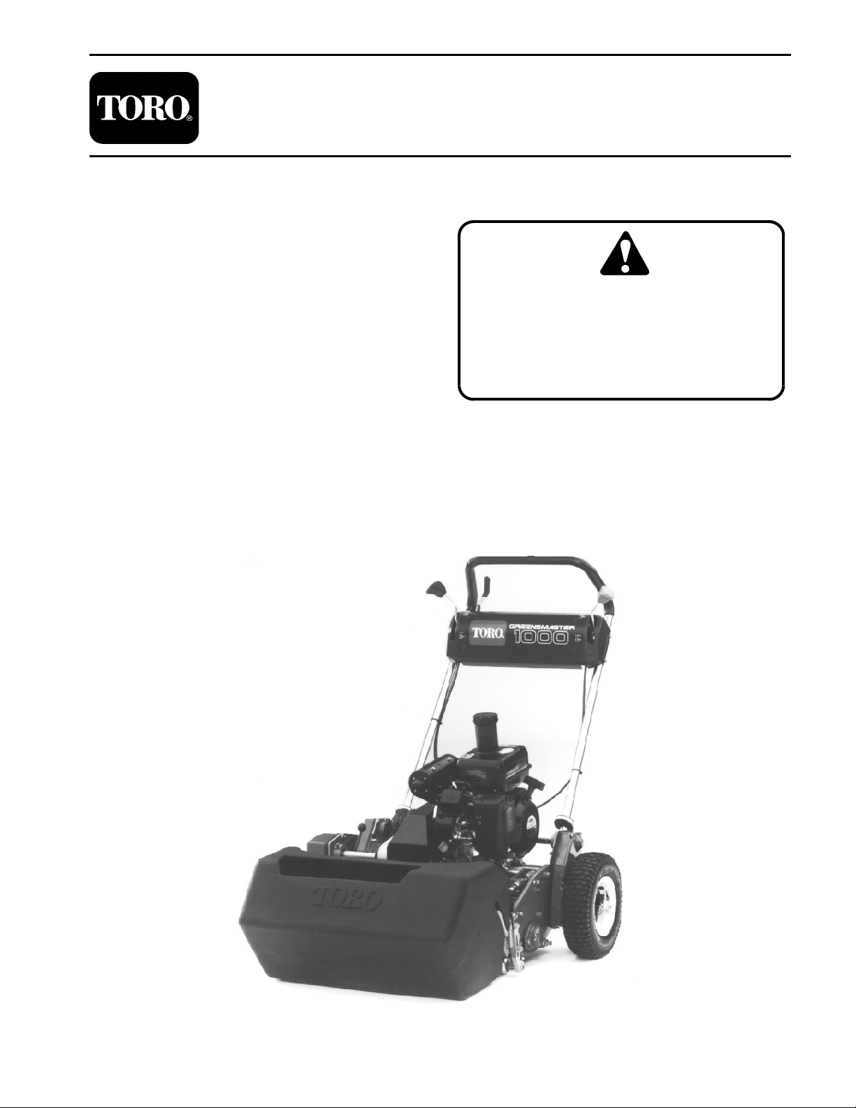
Greensmaster ® 1000/1600
Preface
The purpose of this publication is to provide the service
technician with information for troubleshooting, testing,
and repairing assemblies and components on the
Greensmaster 1000/1600.
REFER TO THE OPERATOR’S MANUAL FOR OPERATING, MAINTENANCE, AND ADJUSTMENT
INSTRUCTIONS. Space is provided in Chapter 2 of this
book to insert the Operator’s Manual and Parts Catalogs
for your machine. Replacement Operator’s Manuals are
available by sending complete Model and Serial Number to:
The Toro Company
8111 Lyndale Avenue South
Minneapolis, MN 55420–1196
The Toro Company reserves the right to change product
specifications or this publication without notice.
PART NO. 96889SL, Rev. A
Service Manual
This safety symbol means DANGER, WARNING, or CAUTION, PERSONAL SAFETY
INSTRUCTION. When you see this symbol,
carefully read the instructions that follow.
Failure to obey the instructions may result in
personal injury.
NOTE: A NOTE will give general information about the
correct operation, maintenance, service, testing, or repair of the machine.
IMPORTANT: The IMPORTANT notice will give important instructions which must be followed to prevent damage to systems or components on the
machine.
The Toro Company – 1996, 1997
Page 2

Greensmaster 1000/1600
Page 3

Table Of Contents
Chapter 1 – Safety
Safety Instructions 1 – 1. . . . . . . . . . . . . . . . . . . . . . . . . .
Safety and Instruction Decals 1 – 4. . . . . . . . . . . . . . . .
Chapter 2 – Product Records and Manuals
Product Records 2 – 1. . . . . . . . . . . . . . . . . . . . . . . . . . .
Equivalents and Conversions 2 – 2. . . . . . . . . . . . . . . .
Torque Specifications 2 – 3. . . . . . . . . . . . . . . . . . . . . . .
Operation and Service History Report 2 – 5. . . . . . . . .
Chapter 3 – Engine
Introduction 3 – 2. . . . . . . . . . . . . . . . . . . . . . . . . . . . . . . .
Specifications 3 – 3. . . . . . . . . . . . . . . . . . . . . . . . . . . . . .
General Information 3 – 4. . . . . . . . . . . . . . . . . . . . . . . .
Adjustments 3 – 6. . . . . . . . . . . . . . . . . . . . . . . . . . . . . . .
Services and Repairs 3 – 8. . . . . . . . . . . . . . . . . . . . . . .
Kawasaki FE161 & FE170 Service Manual and
Kawasaki FE120 Service Manual Supplement
Chapter 4 – Traction and Reel Drive System
Specifications 4 – 2. . . . . . . . . . . . . . . . . . . . . . . . . . . . . .
Special Tools 4 – 3. . . . . . . . . . . . . . . . . . . . . . . . . . . . . .
Adjustments 4 – 4. . . . . . . . . . . . . . . . . . . . . . . . . . . . . . .
Service and Repairs 4 – 8. . . . . . . . . . . . . . . . . . . . . . . .
Chapter 5 – Electrical System
Wiring Schematics 5 – 2. . . . . . . . . . . . . . . . . . . . . . . . .
Special Tools 5 – 6. . . . . . . . . . . . . . . . . . . . . . . . . . . . . .
Trouble Shooting 5 – 7. . . . . . . . . . . . . . . . . . . . . . . . . . .
Component Testing 5 – 8. . . . . . . . . . . . . . . . . . . . . . . . .
Service and Repairs 5 – 13. . . . . . . . . . . . . . . . . . . . . . .
Chapter 6 – Controls, Wheels and Accessories
Specifications 6 – 2. . . . . . . . . . . . . . . . . . . . . . . . . . . . . .
Adjustments 6 – 3. . . . . . . . . . . . . . . . . . . . . . . . . . . . . . .
Service and Repairs 6 – 4. . . . . . . . . . . . . . . . . . . . . . . .
Chapter 7 – Cutting Unit
Introduction 7 – 2. . . . . . . . . . . . . . . . . . . . . . . . . . . . . . . .
Specifications 7 – 3. . . . . . . . . . . . . . . . . . . . . . . . . . . . . .
General Information 7 – 4. . . . . . . . . . . . . . . . . . . . . . . .
Special Tools 7 – 5. . . . . . . . . . . . . . . . . . . . . . . . . . . . . .
Troubleshooting 7 – 7. . . . . . . . . . . . . . . . . . . . . . . . . . . .
Adjustments 7 – 9. . . . . . . . . . . . . . . . . . . . . . . . . . . . . . .
Service and Repairs 7 – 13. . . . . . . . . . . . . . . . . . . . . . .
Chapter 8 – Grooming Reel Kit (See Note Below)
Specifications 8 – 2. . . . . . . . . . . . . . . . . . . . . . . . . . . . . .
General Information 8 – 3. . . . . . . . . . . . . . . . . . . . . . . .
Troubleshooting 8 – 4. . . . . . . . . . . . . . . . . . . . . . . . . . . .
Adjustments 8 – 6. . . . . . . . . . . . . . . . . . . . . . . . . . . . . . .
Service and Repairs 8 – 8. . . . . . . . . . . . . . . . . . . . . . . .
SafetyProduct Records
and Manuals
Engine
Drive System
Traction and Reel
Greensmaster 1000/1600
Note: This chapter covers the Model 04125 Grooming
Reel Kit only (for the Greensmaster 1000).
System
Electrical
Wheels andCutting Unit
Accessories
Kit
Grooming Reel
Page 4

Greensmaster 1000/1600
Page 5

Table of Contents
SAFETY INSTRUCTIONS 1. . . . . . . . . . . . . . . . . . . . . .
Before Operating 1. . . . . . . . . . . . . . . . . . . . . . . . . . . .
While Operating 2. . . . . . . . . . . . . . . . . . . . . . . . . . . .
Safety Instructions
Chapter 1
Safety
Safety
Maintenance and Service 2. . . . . . . . . . . . . . . . . . . .
SAFETY AND INSTRUCTION DECALS 3. . . . . . . . . .
The GREENSMASTER 1000 was tested and certified
by TORO for compliance with the B71.4–1984 specifications of the American National Standards Institute. Although hazard control and accident prevention partially
are dependent upon the design and configuration of the
machine, these factors are also dependent upon the
awareness, concern, and proper training of the personnel involved in the operation, transport, maintenance,
and storage of the machine. Improper use or maintenance of the machine can result in injury or death.
Before Operating
1. Operate the machine only after reading and understanding the contents of this manual. A replacement
manual is available by sending the complete model and
serial number to:
The Toro Company
8111 Lyndale Avenue South
Minneapolis, Minnesota 55420–1196
2. Never allow children to operate the machine, nor allow adults to operate it without proper instructions.
To reduce the potential for injury or death, comply with
the following safety instructions.
WARNING
To reduce the potential for injury or death,
comply with the following safety instructions.
6. Wearing safety glasses, safety shoes, long pants
and a helmet is advisable and required by some local
safety and insurance regulations.
7. Assure work area is clear of objects which might be
picked up and thrown by the reel.
8. Keep everyone, especially children and pets away
from the areas of operation.
9. Gasoline is highly flammable; handle it carefully.
3. Become familiar with the controls, and know how to
stop the engine quickly.
4. Keep all shields, safety devices, and decals in
place. If a shield, safety device, or decal is malfunctioning, illegible, or damaged, repair or replace it before operating the machine.
5. Always wear substantial shoes. Do not operate machine while wearing sandals, tennis shoes or sneakers.
Do not wear loose fitting clothing which could get caught
in moving parts and cause personal injury.
Greensmaster 1000/1600
Page 1 – 1
A. Use an approved gasoline container.
B. Do not remove cap from fuel tank when engine is
hot or running.
C. Do not smoke while handling gasoline.
D. Fill fuel tank outdoors and no higher than to the
bottom of filter screen. Do not overfill.
E. Wipe up any spilled gasoline.
F. Fuel may leak from filler neck when mower is
tilted for servicing if tank is over filled.
Safety
Page 6

10. Check the safety interlock switch daily for proper operation; see Component Testing in Chapter 5 – Electrical System. Replace malfunctioning switches before
While Operating
operating machine. (After every two years, replace the
interlock switch in the safety system, whether it is working properly or not.)
1 1. Do not run the engine in a confined area without adequate ventilation. Exhaust fumes are hazardous and
could be deadly.
12. Always stand behind the handles when starting and
operating the machine.
13. To start and stop the engine:
A. Open fuel shut-off valve.
B. Verify that the traction drive lever on handle is in
NEUTRAL position and reel drive lever on mower is
DISENGAGED.
C. Move on/of f switch to ON position, set choke to
full choke position (cold start) and throttle to half
throttle.
D. Pull starter cord to start engine.
E. Move throttle to SLOW and on/off switch to OFF
position to stop engine.
14. To transport mower from one area to another:
A. Install transport wheels.
B. Disengage reel drive lever.
15. Before beginning mowing operation:
A. Stop engine.
B. Disengage traction drive.
C. Remove transport wheels.
D. Engage reel drive lever.
16. Before emptying basket of clippings, disengage
traction drive, reduce engine speed and move on/off
switch to off position.
17. Do not touch engine, muffler or exhaust pipe while
engine is running or soon after it has stopped because
these areas are hot enough to cause burns.
18. If the cutting unit strikes a solid object or vibrates ab-
normally, stop immediately, turn engine off,wait for all
motion to stop and inspect for damage. A damaged reel
or bedknife must be repaired or replaced before operation is commenced.
19. Whenever machine is left unattended, be sure en-
gine is stopped and cutting unit reel is not spinning.
Close fuel shut-off valve if machine is not to be used for
an extended period of time.
Safety
C. Start engine.
D. Press down on handle to raise front of mower
and engage traction drive.
Maintenance and Service
20. Before servicing or making adjustments to the machine, stop the engine and pull the spark plug wire off
spark plug to prevent accidental starting of the engine.
21. To make sure entire machine is in good condition,
keep all nuts, bolts, screws and belts properly tightened.
22. If major repairs are ever needed or assistance is required, contact an Authorized TORO Distributor.
23. To reduce potential fire hazard, keep the engine
area free of excessive grease, grass, leaves and accumulation of dirt.
24. If the engine must be running to perform a maintenance adjustment, keep hands, feet, clothing, and any
parts of the body away from the cutting unit and any
moving parts. Keep everyone away.
25. Do not overspeed the engine by changing governor
settings. Maximum engine speed is 3600 rpm. To assure safety and accuracy , have an Authorized Toro Distributor check maximum engine speed with a
tachometer.
26. Engine must be shut off before checking oil or ad-
ding oil to the crankcase.
27. To be sure of optimum performance and safety, al-
ways purchase genuine TORO replacement parts and
accessories. Replacement parts and accessories made
by other manufacturers could be dangerous. Such use
could void the product warranty of The Toro Company.
Safety
Page 1 – 2
Greensmaster 1000/1600
Page 7
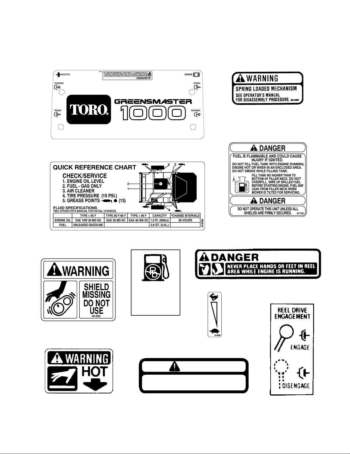
Safety and Instruction Decals
The following safety and instruction decals are affixed to
the traction unit. If any decal becomes illegible or damaged, install a new decal. Part numbers are listed below
On Control Panel
Part No. 93–6084
and in your Parts Catalog. Order replacements from
your Authorized Toro Distributor.
On Front Frame Tube
Part No. 55–4300
Inside Belt Covers (3)
Part No. 88–8950
On Grass Shield
Part No. 93–6098
GAS
UNLEADED
On Fuel Tank
Part No. 53–4420
On Fuel Tank
Part No. 88–7620
On Grass Shield
Part No. 62–5070
On Control Panel
Part No. 93–6085
DANGER
DO NOT OPERATE THIS UNIT UNLESS
ALL SHIELDS ARE FIRMLY SECURED.
On Fuel Tank
Part No. 63–8440
Greensmaster 1000/1600
Inside Belt Cover
Part No. 675360
Page 1 – 3
On Belt Cover
Part No. 65–7660
Safety
Page 8

On Control Panel
Part No. 93–9012
Safety
Page 1 – 4
Greensmaster 1000/1600
Page 9

Table of Contents
Chapter 2
Product Records and Manuals
PRODUCT RECORDS 1. . . . . . . . . . . . . . . . . . . . . . . . .
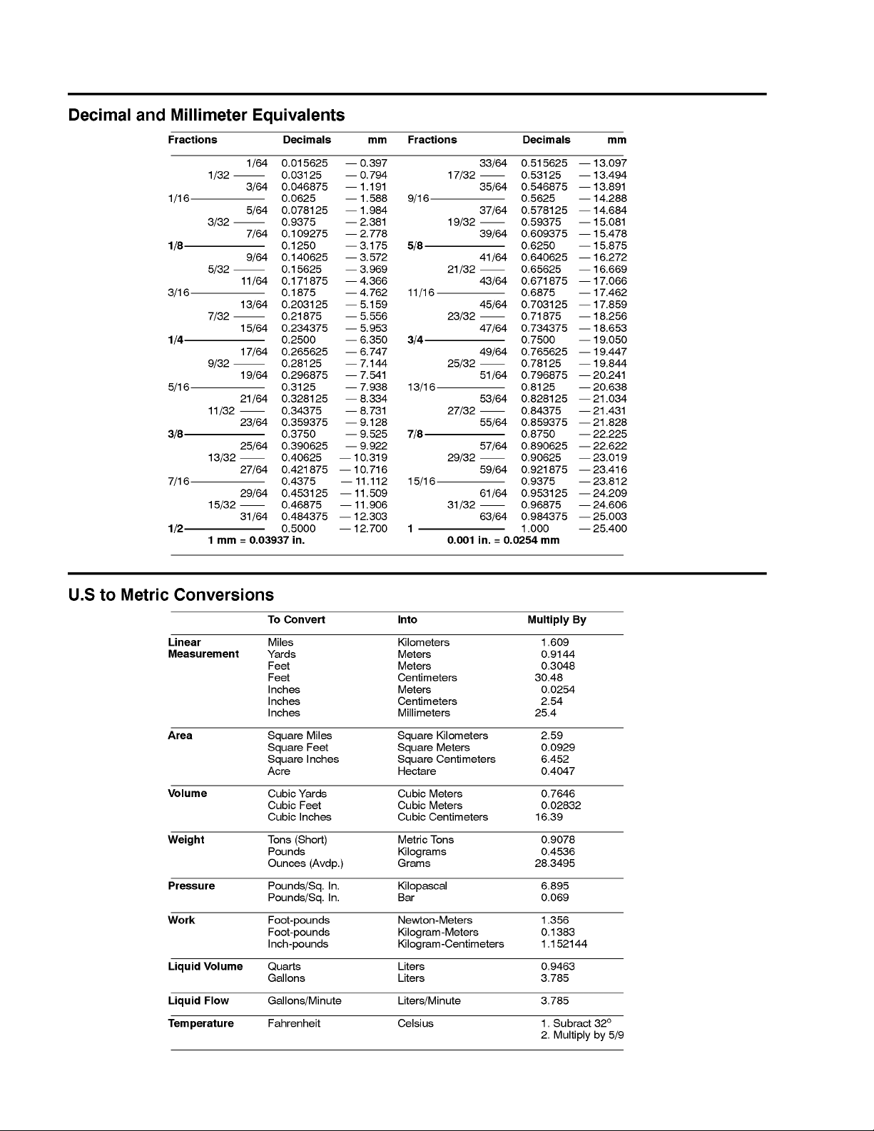
EQUIVALENTS AND CONVERSIONS 2. . . . . . . . . . .
Decimal and Millimeter Equivalents 2. . . . . . . . . . . .
U.S. to Metric Conversions 2. . . . . . . . . . . . . . . . . . .
Product Records
Record information about your Greensmaster
1000/1600 on the OPERATION AND SER VICE HISTORY REPORT form. Use this information when referring
to your machine.
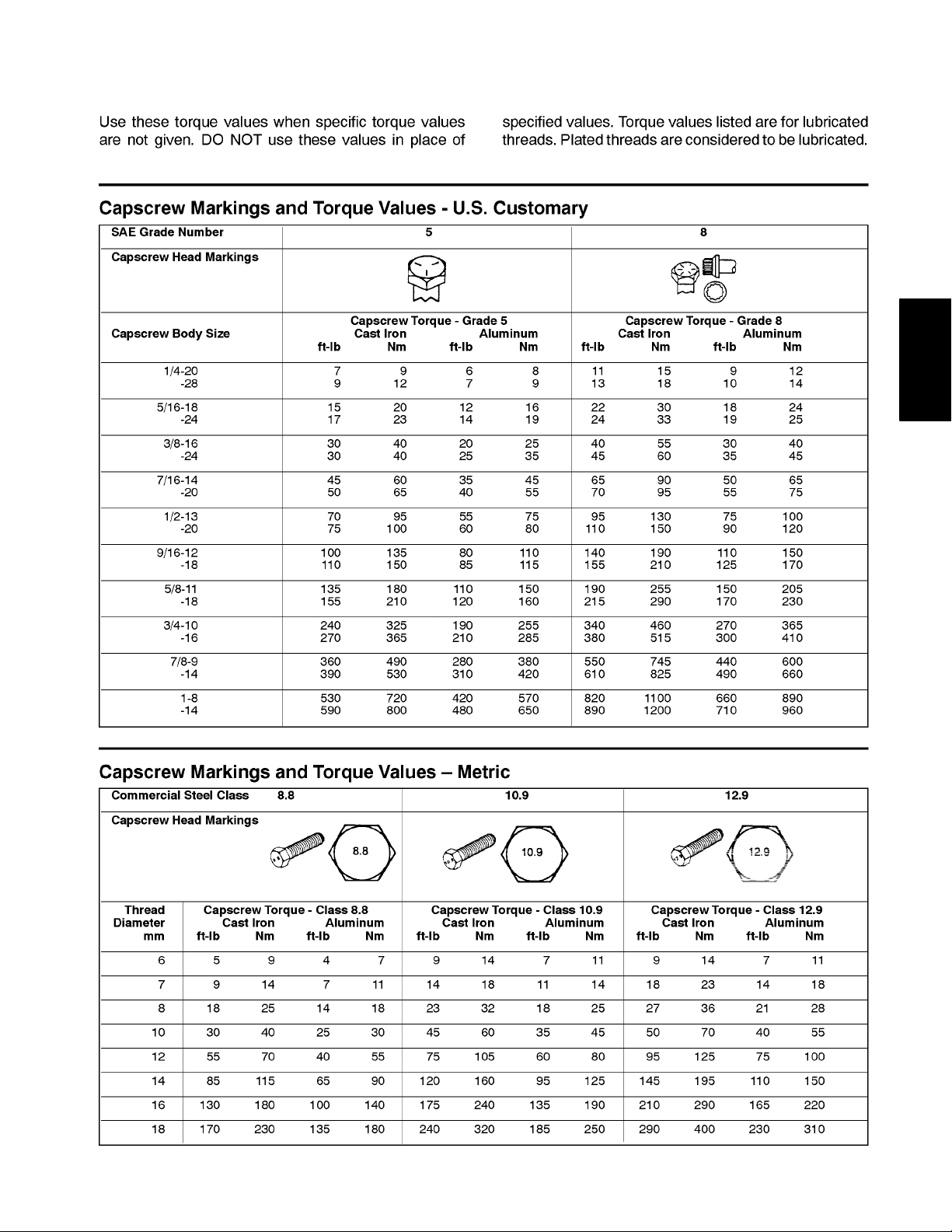
TORQUE SPECIFICATIONS 3. . . . . . . . . . . . . . . . . . .
Capscrew Markings and Torque Values – U.S. 3. .
Capscrew Markings and Torque Values – Metric 3
OPERATION AND SERVICE HISTORY REPORT 5.
Insert Operator’s Manuals and Parts Catalogs for your
Greensmaster 1000/1600 at the end of this section.
and Manuals
Product Records
Greensmaster 1000/1600
Page 2 – 1
Product Records and Manuals
Page 10
Equivalents and Conversions
Product Records and Manuals
Page 2 – 2
Greensmaster 1000/1600
Page 11
Torque Specifications
and Manuals
Product Records
Greensmaster 1000/1600
Page 2 – 3
Product Records and Manuals
Page 12

Product Records and Manuals
Page 2 – 4
Greensmaster 1000/1600
Page 13

EQUIPMENT OPERATION AND SERVICE HISTORY REPORT
for
GREENSMASTER® 1000
TORO Model and Serial Number:__________-__________
Engine Numbers: ____________________
Differential Numbers: ____________________
Date Purchased: ____________________ Warranty Expires__________
Purchased From: ____________________
____________________
____________________
Contacts: Parts ____________________ Phone__________________
Service ____________________ Phone__________________
Sales ____________________ Phone__________________
See your TORO Distributor/Dealer for other Publications, Manuals, and Videos from The TORO Company.
Page 14

GREENSMASTER® 1000 Maintenance Schedule
Minimum Recommended Maintenance Intervals:
Maintenance Procedure Maintenance Interval & Service
Service Air Filter Pre-Cleaner Every
Lubricate All Grease Fittings
Check for loose Fasteners
25hrs
A Level
Every
50hrs
Every
100hrs
Clean Fuel Filter and Sediment Bowl
Adjust Traction Drive Belts B Level
† Change Engine Oil
1
Clean Combustion Chamber
1
Replace Spark Plug
Service
Check Cut-Off Bar Adjustment C Level
Service Air Cleaner Filter
2
Clean Combustion Chamber
2
Replace Spark Plug D Level
Adjust Valves and Torque Head Bolts
Service
Service
† Initial Break in at 20 hours
1
Interval for Engine Model: FG150
2
Interval for Engine Model: FE120
Every
200hrs
Replace All Interlock Switches
Annual Recommendations:
Item listed is recommended every 2 years.
(See Operator's and Service Manual for specifications and procedures)
Page 15

GREENSMASTER® 1000 Daily Maintenance Check List
Unit Designation:__________
Daily Maintenance:(duplicate this page for routine use) TORO ID#:_______-_______
Daily Maintenance Check For Week Of
_____________
Maintenance Check Item
Safety Interlock Operation
Park Brake Operation
Fuel Level
Engine Oil Level
Air Filter Pre-Cleaner
Clean Engine Cooling Fins
Unusual Engine Noises
Unusual Operating Noises
Reel-to-Bedknife Adjustment
Height-of-Cut Adjustment
Lubricate All Grease Fittings
Touch-up damaged paint
1
= Immediately after every washing, regardless of the interval listed.
1
MON
_______HRS
TUES
______HRS
WED
______HRS
THURS
______HRSFR______HRS
SAT
______HRS
SUN
______HRS
Notation for areas of concern: Inspection performed by:________________
Item Date Information
1
2
3
4
5
6
7
(See Operator's and Service Manual for specifications and procedures)
Page 16
GREENSMASTER® 1000 Supervisor Maintenance Work Order Date:______________
(duplicate this page for routine use)
Unit Designation: TORO I.D. #: Remarks:
____________-____________
Hours:
Service to perform (circle):
Technician:
A B C D Other
A -Service (every 25 hours) B -Service (every 50 hours) C -Service (every 100 hours)
Lubricate All Grease Fittings Change Engine Oil
Service Air Filter Pre-Cleaner Adjust Belts
Clean Combustion Chamber
Replace Spark Plug
1
Check for Loose Fasteners Clean Fuel Filter & Sediment Bowl Check Cut-Off Bar Adjustment
_______________________________
A-Service required
Service Air Cleaner Filter
_______________________________ _______________________________ A and B Service required
_______________________________ _______________________________ ________________________________
_______________________________ _______________________________ _______________________________
1
D -Service (every 200 hours) Other - Annual Service and Specials Additional Servicing Items
Clean Combustion Chamber
Replace Spark Plug
2
2
Adjust Valves and Torque Head Bolts _______________________________ _______________________________
A, B and C Service required
Replace all Interlock Switches ________________________________
_______________________________ _______________________________
_______________________________ _______________________________
_______________________________ _______________________________ _______________________________
_______________________________ _______________________________ _______________________________
_______________________________ _______________________________ _______________________________
1
Interval for Engine Model: FG150
2
Interval for Engine Model: FE120
(See Operator's and Service Manual for specifications and procedures) Form No. 95-843-SL
Page 17

Table of Contents
Chapter 3
Engine
INTRODUCTION 2. . . . . . . . . . . . . . . . . . . . . . . . . . . . . .
SPECIFICA TIONS 3. . . . . . . . . . . . . . . . . . . . . . . . . . . .
GENERAL INFORMATION 4. . . . . . . . . . . . . . . . . . . . .
Filling the Fuel Tank 4. . . . . . . . . . . . . . . . . . . . . . . . .
Fuel Shut–off Valve 5. . . . . . . . . . . . . . . . . . . . . . . . . .
ADJUSTMENTS 6. . . . . . . . . . . . . . . . . . . . . . . . . . . . . .
Throttle Linkage Adjustment 6. . . . . . . . . . . . . . . . . .
Clutch Control Adjustment 6. . . . . . . . . . . . . . . . . . . .
Adjusting V–belts 7. . . . . . . . . . . . . . . . . . . . . . . . . . .
SERVICE AND REPAIRS 8. . . . . . . . . . . . . . . . . . . . . .
Engine Oil 8. . . . . . . . . . . . . . . . . . . . . . . . . . . . . . . . . .
Spark Plug and Ignition Components 8. . . . . . . . . .
Air Cleaner 9. . . . . . . . . . . . . . . . . . . . . . . . . . . . . . . . .
Fuel Filter 9. . . . . . . . . . . . . . . . . . . . . . . . . . . . . . . . . .
Engine Removal and Installation 10. . . . . . . . . . . . .
Lubrication 13. . . . . . . . . . . . . . . . . . . . . . . . . . . . . . . .
Kawasaki FE161 & FE170 Service Manual and
Kawasaki FE120 Service Manual Supplement
Engine
Greensmaster 1000/1600 Page 3 – 1 Engine
Page 18

Introduction
This Chapter gives information about specifications,
maintenance, troubleshooting, testing, and repair of the
gasoline engine used in the Greensmaster 1000/1600
mower.
Most repairs and adjustments require tools which are
commonly available in many service shops. Special
tools are described in the Kawasaki FE161 & FE170
Service Manual and Kawasaki FE120 Service Manual
Supplement. The use of some specialized test equipment is explained. However, the cost of the test equipment and the specialized nature of some repairs may
dictate that the work be done at an engine repair facility .
Service and repair parts for Kawasaki engines are supplied through your local T oro distributor . If no parts list is
available, be sure to provide your distributor with the
Toro model and serial number.
Engine
Page 3 – 2
Greensmaster 1000/1600
Page 19

Specifications
Item Description
Make / Designation Kawasaki, 4–stroke, OHV , single cylinder,
air–cooled, gasoline engine, FE120G
Bore x Stroke mm (in.) 60 x 44 (2.36 x 1.73)
Total Displacement cc (cu. in.) 124 (7.6)
Compression Ratio 8.4:1
Maximum Output kw (HP) 2.8 (3.7)
Rated Output kw (HP) 2.2 (3.0)
Carburetor Float feed fixed main jet
Governor Mechanical flyweight
Idle Speed (no load) 1600 100 RPM (at crankshaft) or 800 50 RPM (at camshaft)
High Idle (no load) 3600 100 RPM (at crankshaft) or 1800 50 RPM (at camshaft)
Direction of rotation Clockwise (facing PTO shaft)
Fuel Un–leaded automotive grade gasoline
Fuel Tank Capacity liter (U.S. qt.) 2.5 (2.6)
Engine
Engine Oil See General Information
Lubrication System Splash type
Oil Capacity liter (U.S. qt.) 0.6 (0.63)
Air Cleaner Dual element
Ignition System Transistorized flywheel magneto with ignition advancing
RFI Suppressor Radio suppressor plug cap and plug
Dry Weight kg (U.S. lb) 14.6 (32.2)
Greensmaster 1000/1600 Page 3 – 3 Engine
Page 20
General Information
Filling the Fuel Tank
DANGER
+) )&#!% !) #$$# +*!&%
$+)* +) - % )*&(!% &( %#!% !*
& %&* !## * +# *%" - !# %!% !) (+%0
%!% &* &( !% % %#&) ( '&()
$/ +!# +' % !%!* / )'(" &(
#$ )&+( $%/ * -/
- !# !##!% * +# *%" *& '(0
,%* * '&))!!#!*/ & % .'#&)!&% #0
-/) !## +# *%" &+*)! !' +' %/
)'!## )&#!% &( )*(*!% * %0
!% ) +%%# &( )'&+* *& '(,%* )'!#0
#!% )&#!% !## *%" %& ! ( * % *&
* &**&$ & !#*( )(%
*&( )&#!% !% #% )*/ '0
'(&, &%*!%( % "' * ' &% *
&%*!%( ' )&#!% !% &&# -##
,%*!#* '# %,( !% % %#&)
( )+ ) &* )*&( ) & )0
)+( ,&#*!#!*/ & %&* +/ $&( * %
/ )+''#/ & )&#!% )&#!% !) +#
&( !%*(%# &$+)*!&% %!%) * (0
&( & %&* +) !* &( %/ &* ( '+('&)
!% $%/ !#(% #!" * )$## & )
"' !* &+* & * !( ( +) *
+$) ( .'#&)!, % %(&+) *& !%0
#
1
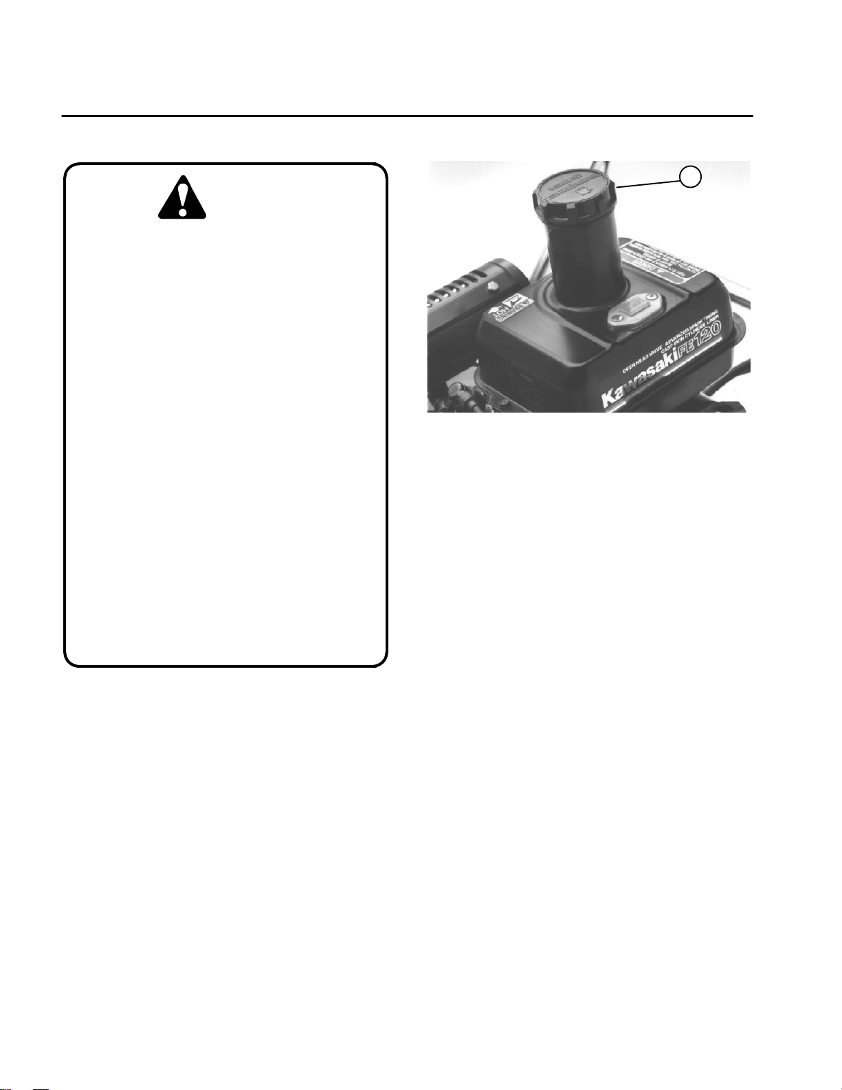
Figure 1
1. Fuel tank cap
IMPORTANT: Never use methanol, gasoline containing methanol, gasoline containing more than
10% ethanol, gasoline additives, premium gasoline,
or white gas. Engine fuel system damage could result.
1. Park mower on a level surface. Make sure engine
is OFF.
2. Clean around fuel tank cap and remove cap from
tank (Fig. 1). Using unleaded gasoline, fill fuel tank to
bottom of filter screen. DO NOT OVER FILL.
Engine
3. Install fuel tank cap. Wipe up any spilled gasoline.
Page 3 – 4
Greensmaster 1000/1600
Page 21
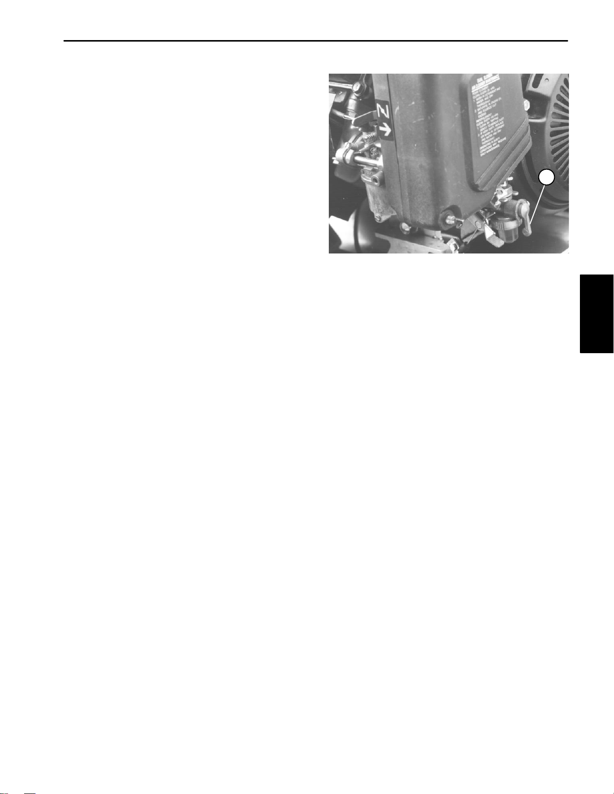
Fuel Shut–off Valve
The valve is located on the left front side of the engine.
It has two positions: CLOSED and OPEN. Position valve
to the closed position when storing or transporting the
machine. Open valve before starting the engine.
1
Figure 2
1. Fuel shut–off valve
Engine
Greensmaster 1000/1600 Page 3 – 5 Engine
Page 22
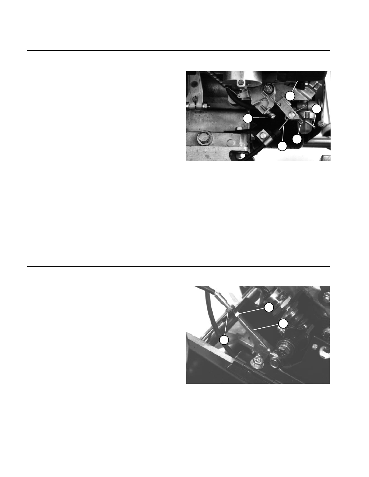
Adjustments
Throttle Control Adjustment
If a new throttle cable must be installed or the cable is
out of adjustment, adjust the cable as follows:
1.Park mower on a level surface. Make sure engine
is OFF. Remove high tension lead from the spark plug.
2.Move throttle lever to the SLOW position.
3.Loosen throttle cable screw securing the throttle
cable to the governor lever.
Note: Engine speed is measured at the input drive
pulley (Fig. 6). Actual engine speed is twice the input
drive pulley speed.
4.The governor lever will move to the slow idle position if it is improperly adjusted.
A. Check low idle speed setting with a tachometer.
Low idle speed should be 750 to 850 rpm. Adjust
low speed idle screw in or out to attain the correct
speed setting.
B. Check high idle speed setting with a tachometer.
High idle speed should be 1750 to 1850 rpm. Adjust high speed idle screw in or out to attain the correct speed setting.
4
3
5
1
2
Figure 2
1. Throttle cable screw
2. Throttle cable
3. Governor lever
4. Low speed idle screw
5. High speed idle screw
5.Make sure throttle lever is in the SLOW position and
the governor lever is against the low speed idle screw.
6.Tighten throttle cable screw securing the throttle
cable to the governor lever.
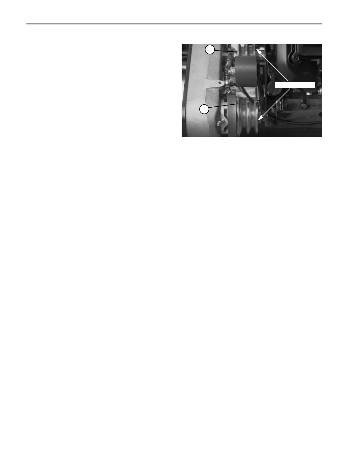
Clutch Control Adjustment
If clutch control does not engage or it slips during operation, an adjustment is required.
1.Park mower on a level surface. Make sure engine
is OFF. Remove high tension lead from the spark plug.
2.Move traction control to DISENGAGED position.
3.Loosen retainer securing V–belt cover and pivot
cover open.
4.To increase cable tension, loosen front cable jam
nut and tighten back cable jam nut (Fig. 3) until a force
of 7 to 9 lbs (31 to 40 N) is required to engage clutch control. The force should be measured at the control knob.
5.Tighten front cable jam nut.
6.Close cover and secure retainer.
7.Check control operation.
3
1. Clutch
2. Front jam nut
2
1
Figure 3
3. Back jam nut
Engine
Page 3 – 6
Rev. A
Greensmaster 1000/1600
Page 23
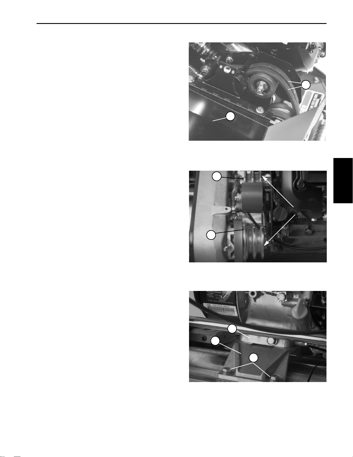
Adjusting V–belts
T o adjust belt tension on V–belts (Fig. 5), first check adjustment of clutch control. Refer to Clutch Control in this
section. If unable to attain the 7 to 9 lbs (31 to 40 N) of
force that is required in adjusting the clutch control, proceed to the next step.
1. Park mower on a level surface. Make sure engine
is OFF. Remove high tension lead from the spark plug.
2. Loosen retainer securing the V–belt cover and pivot
cover open.
3. To increase V–belt tension, loosen cap screws securing the engine to the engine base (Fig. 12). Move engine backwards in slots. DO NOT OVER TENSION
BELTS. Tighten cap screws.
4. Check that a force of 7 to 9 lbs (31 to 40 N) is required to engage the clutch control. Adjust engine in
slots as necessary to get required tension on V–belts.
5. After tensioning V–belts, check alignment of the input drive pulley and input shaft pulley with a straight
edge.
A. Inside pulley faces should be flush to each other
to within 0.030 inch (0.762 mm) maximum (Fig. 6).
B. If pulleys are misaligned, loosen cap screws securing the engine mounting base to the mower
frame. Slide engine from side to side until the pulleys are aligned (Fig. 7).
2
1
Figure 5
1. V–belt cover 2. V–belts
1
Engine
INSIDE FACE
2
6. Tighten cap screws and recheck alignment.
7. Close V–belt cover and secure retainer.
Figure 6
1. Input drive pulley 2. Input shaft pulley
2
3
1
Figure 7
1. Cap screws
2. Engine
3. Engine base
Greensmaster 1000/1600 Page 3 – 7 Engine
Page 24

Service and Repairs
Engine Oil
The TORO Company recommends that the oil level be
checked each time the mower is used or after every 5
operating hours. Initially, change oil after the first 20
hours of operation; thereafter, change oil after every 50
hours of operation. More frequent oil changes are re-
quired in dusty or dirty conditions.
Checking the Oil Level:
1. Park mower on a level surface. Make sure engine
is OFF.
2. Position mower so the engine is level. Clean around
the oil level gauge.
3. Remove oil level gauge by rotating it counterclockwise.
4. Wipe oil level gauge clean and insert it into the filler
port. Do not screw it into the port. Remove and check
level of the oil. If the oil level is low, add only enough oil
(see chart below for proper viscosity) to raise the level
to the filler opening.
Use any high quality detergent oil having the American
Petroleum Institute (API) “service classification”— MS
or SG.
Changing the Oil:
1. Start and run engine for a few minutes to warm the
engine oil.
2. Place a drain pan at the rear of machine under the
drain plug. Remove drain plug.
3. Push down on handle to tip mower and engine backward, allowing more oil to run into the drain pan.
4. Reinstall drain plug and refill crankcase with proper
oil: refer to Checking the Oil Level. The crankcase
holds 6.3 qt (6.0 l).
1
T emperature Oil Viscosity
50 or below SAE 10W30 wt.
50 to 95 SAE 10W30 wt. or 30 wt.
Above 95 SAE 40
5. Reinstall oil level gauge and wipe up any spilled oil.
Spark Plug and Ignition Components
Service of the spark plug and other ignition components
is covered in Chapter 5 – Electrical System.
2
Figure 8
1. Oil level gauge 2. Drain plug
Engine
Page 3 – 8
Greensmaster 1000/1600
Page 25
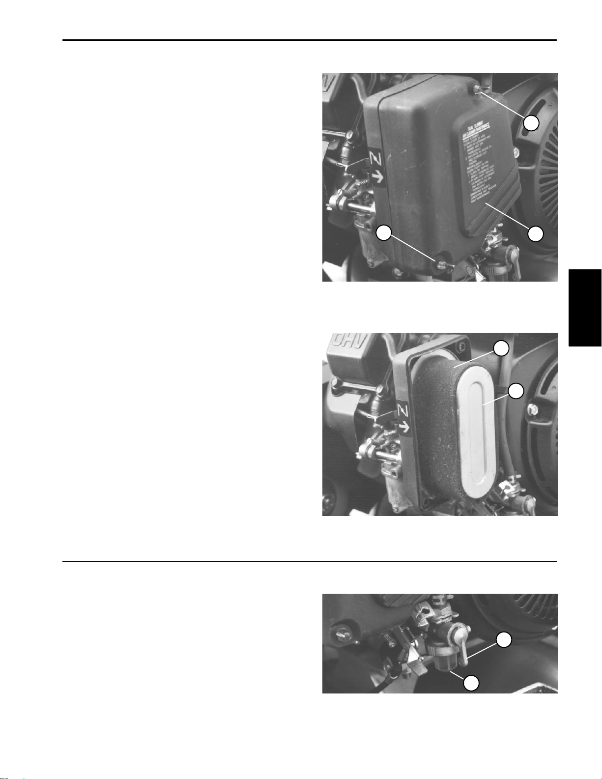
Air Cleaner
Normally , clean air filter precleaner (foam element) after
every 25 operating hours and the air cleaner filter (paper
element) after every 100 operating hours. More frequent
cleaning is required when the mower is operated in
dusty or dirty conditions. Replace air cleaner filter (paper element) after 200 operating hours.
1. Park mower on a level surface. Make sure engine
is OFF. Remove high tension lead from the spark plug.
2. Remove wing nuts securing the air cleaner cover to
air cleaner and remove cover. Clean cover thoroughly
(Fig. 9).
1
3. If the foam element is dirty , remove it from the paper
element (Fig. 10). Clean foam element thoroughly.
A. WASH element in a solution of liquid soap and
warm water. Squeeze it to remove dirt. Do not twist
element because foam may tear.
B. DRY by wrapping the element in a clean rag.
Squeeze rag and foam element to dry.
C. SATURATE element with clean engine oil.
Squeeze element to remove excess oil and to distribute oil uniformly. An oil damp element is desirable.
4. When servicing the foam element, check condition
of the paper element. Clean or replace as required.
5. Reinstall foam element, paper element, and air
cleaner cover. Tighten wing nuts.
IMPORTANT: Do not operate engine without air
cleaner element because extreme engine wear and
damage will likely result.
1
Figure 9
1. Wing nut 2. Air cleaner cover
1
2
2
Engine
Figure 10
1. Foam element 2. Paper element
Fuel Filter
Clean fuel filter after every 50 hours operation.
1. Close fuel shut off valve and unscrew bowl from the
filter body. Remove filter element.
2. Clean bowl and filter element in clean gasoline
3. Reinstall filter element and bowl. Open fuel shut–off
valve.
2
Figure 11
1. Fuel shut–off valve 2. Bowl
Greensmaster 1000/1600 Page 3 – 9 Engine
1
Page 26
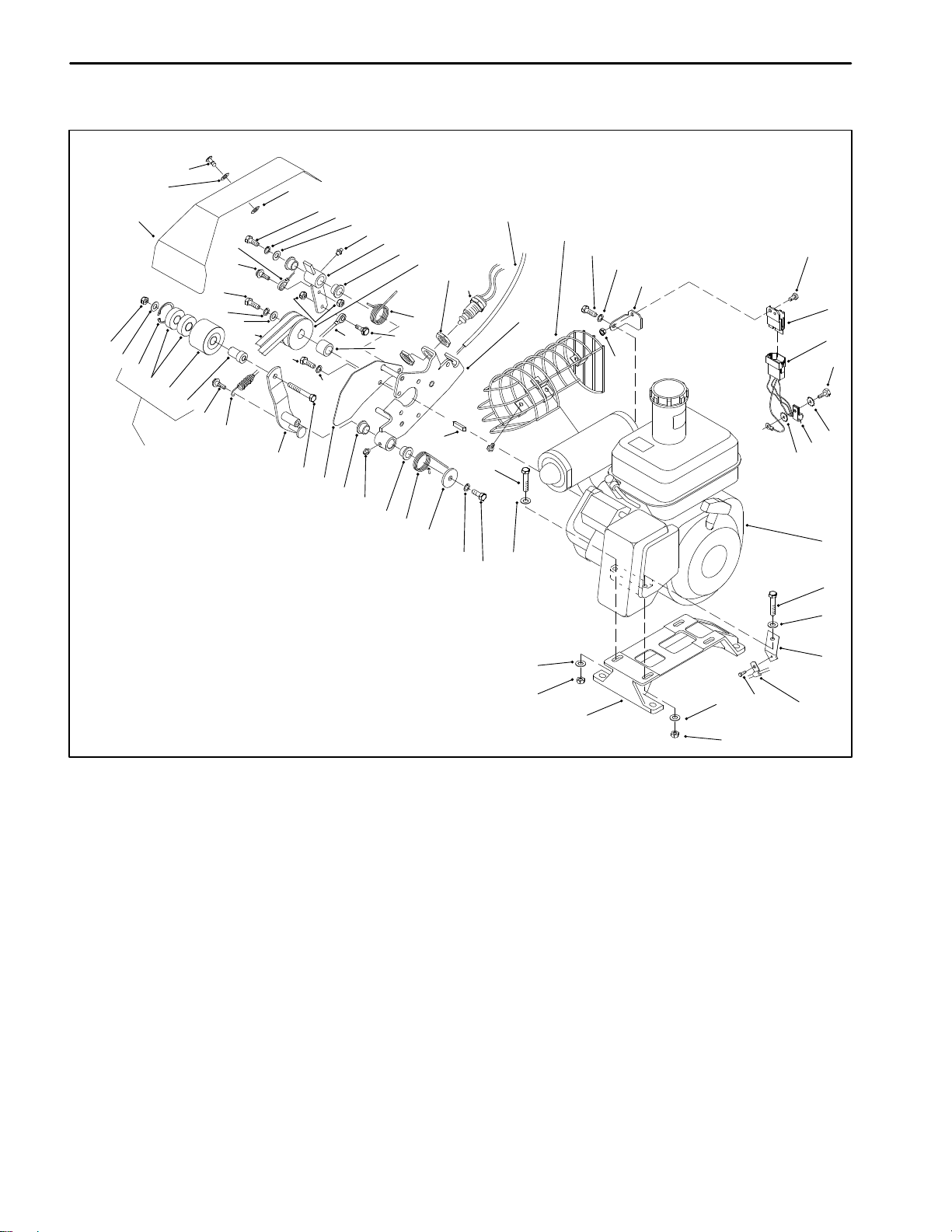
Engine Removal and Installation
3
2
1
42
7
41
40
39
38
IDLER PULLEY
ASSEMBLY
13
36
33
32
49
13
35
34
31
37
20
4
30
29
33
5
6
7
8
9
10
11
15
14
32
13
12
KEY
10
8
10
28
27
16
6
23
5
48
43
20
45
33
44
17
46
22
41
20
19
18
19
21
7
23
7
1. Bellcrank cover
2. Flat washer
3. Stud
4. Retainer
5. Capscrew
6. Lock washer
7. Flat washer
8. Grease fitting
9. Lever
10. Bushing
11. Input drive pulley
12. Engine shaft spacer
13. Shoulder bolt
14. Torsion spring
15. Jam nut
16. Clutch switch
17. Clutch bracket
Figure 12
18. R–clamp
19. Lock washer
20. Cap screw
21. Engine
22. Wire harness
23. Capscrew
24. Throttle cable bracket
25. Washer head screw
26. Lock nut
27. Washer
28. Clutch torsion spring
29. Belt shield
30. Cap screw
31. Clutch lever
32. Cable link assembly
33. Lock washer
34. V–belt (matched set)
7
26 7
50
35. Washer
36. Cap screw
37. Lock nut
38. Pulley support spacer
39. Idler pulley
40. Ball bearing
41. Retaining ring
42. Lock nut
43. Muffler guard (European models)
44. Module bracket
45. Cap screw
46. Interlock module
47. Throttle cable and bracket
48. Clutch cable
49. Clutch cable eyelet
50. Engine base
26
25
24
47
Engine
Page 3 – 10
Greensmaster 1000/1600
Page 27
Removal
1. Make sure machine is parked on a level surface with
the engine OFF. Remove high tension lead from the
spark plug to prevent the engine from starting. Close
fuel shut–off valve.
2. Remove pulley V–belts (Fig. 12).
A. Make sure clutch is DISENGAGED so the V–
belts (34) are slackened. Make sure service brake is
DISENGAGED so the input shaft pulley can turn.
B. Open bellcrank cover (1) on the counter shaft
housing to get access to the clutch. Remove V–
belts one at a time by sliding the belt off the idler
pulley (39) first.
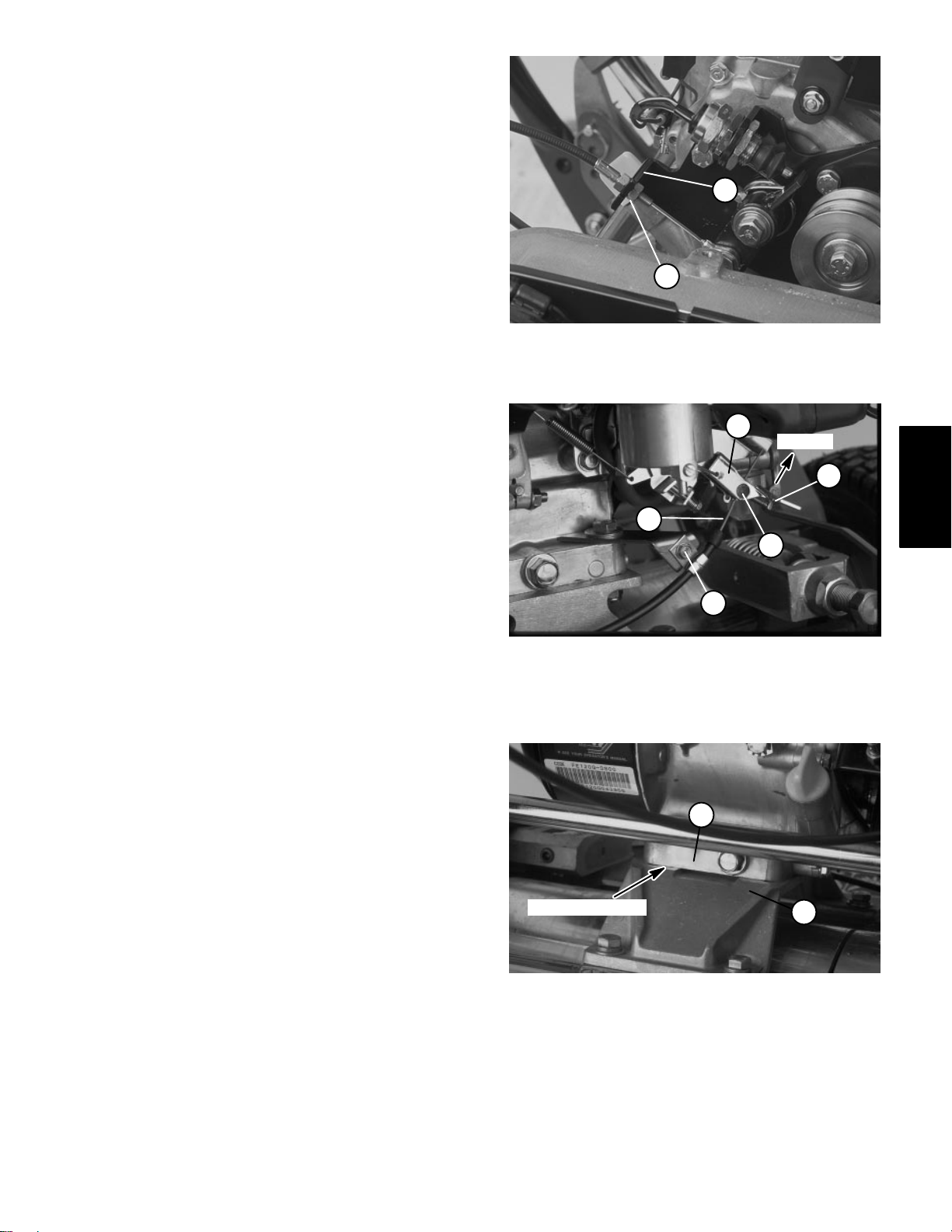
3. Remove clutch cable (Fig. 12).
A. Remove shoulder bolt (13) and lock nut (37)
from the clutch cable eyelet (49) and lever (9).
B. Loosen lower jam nut holding the clutch cable to
the clutch bracket. Remove clutch cable from the
clutch bracket and clear of engine (Fig. 13).
4. Remove throttle cable from engine.
A. Loosen screw on governor lever enough to slide
the throttle cable out of the nut (Fig. 14).
B. Remove cap screw (23), flat washers (7), and
lock nut (26) from the engine base (49) and throttle
cable bracket (24). Pull throttle cable (47) and
bracket clear of the engine (Fig. 12).
5. Remove engine from the engine base.
2
1
Figure 13
1. Lower jam nut 2. Clutch bracket
2
SLOW
3
4
5
Figure 14
1. Screw
2. Governor lever
3. Throttle cable
4. Nut
5. Washer head screw
1
Engine
A. Scribe a mark on the engine base at the bottom
of the engine for reassembly purposes (Fig. 15).
B. Disconnect both black\white wires on the clutch
switch (16) from both brown wires.
1
C. Remove remaining cap screws (23), flat washers (7), and lock nuts (26) from the engine base (49).
Remove the engine from the cutting unit.
SCRIBE MARK
2
6. The bellcrank assembly can be removed from the
engine with minimum disassembly (Fig. 12).
A. Remove cap screw (36), lock washer (33), and
washer (35) from the engine shaft. Remove pulley
1. Engine block 2. Engine base
Figure 15
(11), key, and spacer (12) from the engine shaft.
C. Remove complete bellcrank assembly from the
B. Remove five cap screws (20) and lock washers
engine.
(33) securing the belt shield (29) and clutch bracket
(17) to the engine block.
Greensmaster 1000/1600 Page 3 – 11 Engine
Page 28
Reinstalling the Engine
1. Make sure machine is parked on a level surface.
The machine may be placed on a large work bench to
make engine installation and adjustment easier. Remove high tension lead from the spark plug.
2. Make sure that all parts removed from the engine
during maintenance or rebuilding are properly reinstalled to the engine.
3. Make sure bellcrank cover (1) is open on the counter shaft housing to get access to the clutch (Fig. 12).
4. If the bellcrank assembly was removed from the engine (21), reassembly as follows (Fig. 12):
A. Position clutch bracket (17) to the engine with
the long arm of the clutch torsion spring (28) under
the engine.
B. Position belt shield (29) to the engine. Secure
belt shield and clutch bracket to the engine with five
cap screws (20) and lock washers (33).
C. Hook short end of clutch torsion spring around
the post on the clutch bracket.
D. Place engine shaft spacer (12) on the engine
shaft and reinstall key. Apply never seize to the
shaft.
E. Place input drive pulley (11) on the engine shaft
with the counter bore out. Secure pulley to the shaft
with cap screw (36), lock washer (33), and washer
(35).
5. Reinstall engine (21) to engine base (50) (Fig. 12).
A. Position engine on the engine base with the in-
put drive pulley towards the differential housing.
B. Install four cap screws (23) and flat washers (7)
through the engine and engine base. Install throttle
cable bracket (24) under the left front cap screw. Put
flat washer and lock nut (26) on each cap screw and
hand tighten.
C. Use scribe mark on engine block to align engine.
The distance between engine out put shaft center
and and power shaft center should be from 5.11 to
5.23 inches (130 to 133 mm). Inside pulley faces
should be flush to each other to within 0.030 inch
(0.762 mm) maximum (Fig. 16).
D. Tighten cap screws ensuring the engine alignment does not change.
1
INSIDE FACE
2
Figure 16
1. Input drive pulley 2. Input shaft pulley
6. Reconnect and adjust throttle cable (Fig. 14).
A. Make sure screw on governor level is loose
enough to slide the throttle cable into of the nut.
B. Loosen washer head screw enough to allow the
throttle cable to slide through small clamp
C. Position throttle control lever to the SLOW posi-
tion and governor lever all the way up to the slow
position.
D. Tighten screw on throttle lever and washer head
screw to the small clamp securing the throttle cable.
7. Reinstall clutch cable.
A. Reinstall clutch cable into notch of clutch bracket
and clear of engine. Tighten lower jam nut holding
clutch cable to clutch bracket (Fig. 13).
B. Place shoulder bolt (13) through the clutch cable
eyelet (49) and lever (9). Secure shoulder bolt with
lock nut (37) (Fig. 12).
8. Reinstall pulley V–belts (Fig. 12).
A. Make sure clutch is DISENGAGED. Make sure
service brake is DISENGAGED so the input shaft
pulley can turn.
B. Install V–belts (34) one at a time by placing a belt
into the inner groove of the input drive pulley (11)
first. Place the second belt into the outer groove of
the input drive pulley and then the outer groove of
the input shaft pulley . Place the loose end of the first
belt into the inner groove of the input drive pulley.
E. Reconnect both black\white wires on the clutch
switch (16) to both brown wires.
Engine
Page 3 – 12
Greensmaster 1000/1600
Page 29
Lubrication
Both fittings on the bellcrank assembly should be
greased at least every 25 hours. Lubricate using No. 2
multipurpose lithium base grease. A hand operated
grease gun is recommended for best results.
1. Park mower on a level surface. Make sure engine
is OFF. Remove high tension lead from the spark plug.
2. Wipe each grease fitting with a clean rag.
IMPORTANT: Do not apply too much pressure or
grease seals will become permanently damaged.
3. The grease fitting locations are the clutch lever pivot
and the clutch spring end of the clutch bracket.
4. Wipe off excess grease.
Figure 17
Engine
Greensmaster 1000/1600 Page 3 – 13 Engine
Page 30

Engine
Page 3 – 14
Greensmaster 1000/1600
Page 31

Traction and Reel Drive Systems
Table of Contents
Chapter 4
SPECIFICATIONS 2. . . . . . . . . . . . . . . . . . . . . . . . . . . .
SPECIAL TOOLS 3. . . . . . . . . . . . . . . . . . . . . . . . . . . . .
Drum Bushing Tool Kit 3. . . . . . . . . . . . . . . . . . . . . . .
ADJUSTMENTS 4. . . . . . . . . . . . . . . . . . . . . . . . . . . . . .
Differential Belt Adjustment 4. . . . . . . . . . . . . . . . . . .
Drum Drive Belt Adjustment 5. . . . . . . . . . . . . . . . . .
Reel Drive Belt Adjustment 6. . . . . . . . . . . . . . . . . . .
Service/Park Brake Adjustment 7. . . . . . . . . . . . . . .
SERVICE AND REPAIRS 8. . . . . . . . . . . . . . . . . . . . . .
Reel Drive Assembly 8. . . . . . . . . . . . . . . . . . . . . . . .
Reel Drive Belt Replacement 9. . . . . . . . . . . . . . . . .
Reel Drive Idler Pulley and Bearing 9. . . . . . . . . . . .
Clutch Bearing 10. . . . . . . . . . . . . . . . . . . . . . . . . . . . .
Drum Drive Assembly 12. . . . . . . . . . . . . . . . . . . . . .
Drum Drive Belt Replacement 13. . . . . . . . . . . . . . .
Drum Drive Idler Pulley and Bearing 13. . . . . . . . . .
Differential Axle Pulley and Bearing 14. . . . . . . . . .
Drum Shaft Bearing 15. . . . . . . . . . . . . . . . . . . . . . . .
Drum Assembly with Bearings 16. . . . . . . . . . . . . . .
Drum Assembly with Bushings 18. . . . . . . . . . . . . . .
Counter Shaft Assembly 20. . . . . . . . . . . . . . . . . . . .
Brake Band Replacement 21. . . . . . . . . . . . . . . . . . .
Power Shaft Bearing 22. . . . . . . . . . . . . . . . . . . . . . .
Differential Axle Bearing
(Countershaft Housing) 23. . . . . . . . . . . . . . . . . . . . .
Differential Idler and Bearing 24. . . . . . . . . . . . . . . .
Differential Assembly and Pulley 25. . . . . . . . . . . . .
Differential Belt Replacement – Models 04051,
04052, and 04060 29. . . . . . . . . . . . . . . . . . . . . . .
Differential Belt Replacement – Model 04050 30. .
Lubrication 35. . . . . . . . . . . . . . . . . . . . . . . . . . . . . . . .
Drive System
Traction and Reel
Greensmaster 1000/1600 Traction and Reel Drive SystemsPage 4 – 1
Page 32

Specifications
Item Description
Traction Drive Engine to countershaft drive has two ”A” section V–belts.
Differential Peerless series 100
Brake Band drum
Traction Drum Dual cast aluminum, 7.5 inch (19.1 cm) diameter
Reel Clutch Jaw type
Countershaft to differential drive has 5 mm pitch timing belt.
Differential to drum drive has a 8 mm pitch timing belt.
Greensmaster 1000/1600Traction and Reel Drive Systems Page 4 – 2
Page 33

Special Tools
Order special tools from the
TORO SPECIAL TOOLS
AND APPLICATIONS GUIDE (COMMERCIAL PRODUCTS)
.
Drum Bushing Tool Kit – TOR4060
Note: This kit is used on mowers with drums that have
bushings instead of bearings. The kit is used for models
04051 and 04052 – 50101 to 59999 only.
This kit contains all the tools required to install and properly size the drum bushings to factory standards. These
tools come as a set in a plastic tool case, or they may be
ordered individually .
Some tools may have been supplied with your mower or
available as TORO parts. Some tools may also be available from a local supplier.
REAMER
TOR4061
PILOT
TOR4062–2
ADAPTER SLEEVE
TOR4062–3
BUSHING DRIVER
TOR4062–1
Figure 1
Drive System
Traction and Reel
Greensmaster 1000/1600 Traction and Reel Drive SystemsPage 4 – 3
Page 34

Adjustments
Differential Belt Adjustment
1. Park mower on a level surface. Make sure engine
is OFF. Remove high tension lead from the spark plug.
2. Check tension by depressing belt at the mid span
between pulleys with 5 to 6 lbs (22 to 27 N) of force. The
belt should deflect 1/4 inch. If deflection is incorrect, proceed to next step. If deflection is correct, continue operation.
1
3
5
3. To adjust belt tension:
A. Remove capscrews securing the front and rear
box covers to countershaft housing. Slide covers
away from the housing to expose the belt (Fig. 2).
B. Loosen idler pulley cap screw on the engine side
of the housing (Fig. 3).
C. Pivot idler pulley clockwise against the backside
of the belt until desired belt tension is attained. Do
not over tension the belt (Fig. 2).
D. Tighten cap screw to lock adjustment (Fig. 3).
E. Reinstall box covers by placing the covers in
position. While maintaining a slight gap between the
cover seal and the side plate, install each cap screw
until the threads engage in the insert. The gap will
allow visual alignment of the cap screw to the
threaded insert. After all cap screws are installed,
tighten them until the stand offs inside the covers
contact the side plate. Do not overtighten (Fig. 2).
2
4
Figure 2
1. Front box cover
2. Rear box cover
3. Countershaft housing
4. Idler pulley
5. Differential belt
1
2
Figure 3
1. Cap screw 2. Countershaft housing
Greensmaster 1000/1600Traction and Reel Drive Systems Page 4 – 4
Page 35

Drum Drive Belt Adjustment
1. Park mower on a level surface. Make sure engine
is OFF. Remove high tension lead from the spark plug.
2. Check tension by depressing belt at mid span between the pulleys with 4 to 5 lbs (18 to 22 N) of force. The
belt should deflect 1/4 inch. If deflection is incorrect, proceed to next step. If deflection is correct, continue operation.
3. To adjust belt tension:
A. Remove wheels if installed.
B. Remove cap screws, lock washers, and belt cov-
ers from the side plates (Fig. 4).
C. Loosen idler pulley capscrew (Fig. 5).
D. Pivot the idler pulley clockwise against the back-
side of the belt until desired belt tension is attained.
Do not over tension belt (Fig. 6).
E. Tighten cap screw to lock adjustment (Fig. 5).
Note: Make sure spacer is on the lower pulley before
the belt cover is reinstalled.
F. Reinstall belt cover by placing the cover in position. While maintaining a slight gap between the
cover seal and the side plate, install each cap screw
until the threads engage in the insert. The gap will
allow visual alignment of the cap screw to the
threaded insert. After all capscrews are installed,
tighten them until the stand offs inside the cover
contact the side plate. Do not overtighten (Fig. 6).
2
1
1
Figure 4
1. Cap screw & lock washer 2. Belt cover
1
2
Drive System
Traction and Reel
Figure 5
1. Cap screw 2. Engine base
Greensmaster 1000/1600 Traction and Reel Drive SystemsPage 4 – 5
1
2
Figure 6
1. Drum drive belt 2. Idler pulley
Page 36

Reel Drive Belt Adjustment
1. Park mower on a level surface. Make sure engine
is OFF. Remove high tension lead from the spark plug.
2. Check tension by depressing the belt at mid span
between pulleys with 4 to 5 lbs (18 to 22 N) of force. The
belt should deflect 1/4 inch. If deflection is incorrect, proceed to next step. If deflection is correct, continue operation.
3. To adjust belt tension:
A. Remove cap screws, lock washers, and belt cov-
ers to expose the belt (Fig. 7).
B. Remove cap screws, flat washers, and nuts se-
curing the grass shield to the shield brackets. Move
grass shield to access the cap screw securing the
idler pulley (Fig. 8).
C. Loosen idler pulley cap screw (Fig. 8).
D. Pivot the idler pulley clockwise against the back-
side of the belt until desired belt tension is attained.
Do not over tension belt (Fig. 9).
E. Tighten cap screw to lock adjustment (Fig. 8).
3
Figure 7
1. Cap screw & lock washer 2.
5
4
3
F. Reinstall belt cover by placing the cover in position. While maintaining a slight gap between the
cover seal and the side plate, install each cap screw
until the threads engage in the insert. The gap will
allow visual alignment of the cap screw to the
threaded insert. After all cap screws are installed,
tighten them until the stand offs inside the cover
contact the side plate. Do not overtighten (Fig. 9).
G. Reinstall grass shield to shield brackets with cap
screws, flat washers, and lock nuts (Fig. 8).
3
1
2
Figure 8
1. Cap screw, washer & nut
2. Grass shield
3. Shield bracket
4. Cap screw
5. Idler pulley
1
2
1
2
Figure 9
1. Reel drive belt 2. Idler pulley
Greensmaster 1000/1600Traction and Reel Drive Systems Page 4 – 6
Page 37

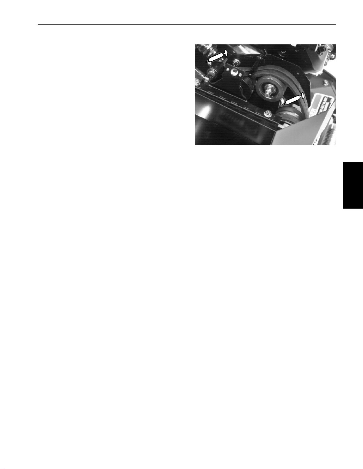
Service/Park Brake Adjustment
If service/park brake slips when operated, an adjustment is required.
1
1. Park mower on a level surface. Make sure engine
is OFF. Remove high tension lead from the spark plug.
2. Move service/park brake lever to the OFF position.
Note: Figure 10 is shown with the bellcrank cover re-
moved for illustrative purposes. It is not necessary to remove the cover.
3. Loosen retainer securing the bellcrank cover. Pivot
cover open.
4. To increase cable tension, loosen front cable jam
nut and tighten back cable jam nut until a force of 3 to 5
lbs (13 to 22 N) is required to engage brake. The force
should be measured at brake lever knob. Do not over
adjust, so brake band drags.
5. Close cover and secure retainer.
2
Figure 10
1. Brake cable 2. Front jam nut
Drive System
Traction and Reel
Greensmaster 1000/1600 Traction and Reel Drive SystemsPage 4 – 7
Page 38

Service and Repairs
Reel Drive Assembly
52
49
55
41
17
56 57
48
47
4546
54
50
53
51
15
42
32
30
16
44
42
15
14
13
43
12
58
18
11
31
12
26
22
25
27
29
28
5
1
19
20
23
21
24
10
8
7
4
40
3
9
6
47
RIGHT
FRONT
1. Clutch housing
2. Cap screw
3. Lock nut
4. Ball bearing
5. Grease fitting
6. Oil seal
7. Wave washer
8. Retaining ring
9. Power shaft
10. Key (2)
11. Clutch jaw driver
12. Clutch and pulley assembly
13. Ball bearing
14. Retaining ring
15. Retaining ring
16. Lock washer
17. Jam nut
18. Felt seal
19. Actuator pin
20. Detent spring
39
38
37
36
34
Figure 11
21. Lock nut
22. Lock washer
23. Drive screw
24. Clutch lever
25. Spacer
26. Washer
27. Cap screw
28. Clutch boot
29. Knob
30. Groomer arm cover
31. Cover trim
32. Flat head screw
33. Nut
34. Bearing housing
35. Seal
36. Cover standoff
37. Self–aligning bearing
38. Retaining ring
39. Seal
5
2
35
33
40. Wave washer
41. Reel drive belt
42. Pulley and drive assembly
43. Idler pulley
44. Ball bearing
45. Snap ring
46. Flat washer
47. Lock washer
48. Cap screw
49. Reel drive cover
50. Front seal strip
51. Rear seal strip
52. Upper seal strip
53. Lower seal strip
54. Plug
55. Decal
56. Cap screw
57. Washer
58. Pulley support spacer
Greensmaster 1000/1600Traction and Reel Drive Systems Page 4 – 8
Page 39

Reel Drive Belt Replacement
Removal
1. Park mower on a level surface. Make sure engine
is OFF. Remove high tension lead from the spark plug.
2. Remove cap screws (56), washers (57) and reel
drive cover (49) to expose reel drive belt (41) (Fig. 1 1).
3. Remove cap screws, flat washers, and nuts securing grass shield to shield brackets. Move grass shield to
access the cap screw securing the idler pulley (Fig. 8).
4. Loosen cap screw (2) securing the pulley support
spacer (58) (Fig. 11).
5. Pivot idler pulley counterclockwise away from the
reel drive belt to loosen belt tension. Remove reel drive
belt from the clutch pulley and drive pulley (Fig. 12).
Installation
1. Park mower on a level surface. Make sure engine
is OFF. Remove high tension lead from the spark plug.
2. Place a new reel drive belt onto the clutch pulley and
drive pulley (Fig. 12).
3. Adjust reel drive belt tension and reinstall reel drive
cover (see Reel Drive Belt in the Adjustments section).
4. Reinstall grass shield to shield brackets with cap
screws, flat washers, and lock nuts (Fig. 8).
3
1
2
4
Figure 12
1. Idler pulley
2. Reel drive belt
3. Clutch pulley
4. Drive pulley
Reel Drive Idler Pulley and Bearing
Removal
1. Remove reel drive belt from the reel drive assembly
(see Reel Drive Belt Replacement Removal).
2. Remove cap screw (2) and lock washer (47) from
the pulley support spacer (58). Remove idler pulley assembly from the clutch housing (Fig. 11).
Disassembly (Fig. 13)
Note: The idler pulley assemblies for the reel drive
and drum drive assemblies are identical.
1. Remove cap screw, lock washer, and flat washer
from the pulley support spacer. Pull spacer from the idler
pulley .
2. Remove snap ring. Pull ball bearing from the idler
pulley.
Assembly (Fig. 13)
1. Press new ball bearing into the idler pulley. Press
pulley support spacer into the ball bearing and idler
pulley.
2. Install snap ring into idler pulley . Secure flat washer,
lock washer, and cap screw into the pulley support
spacer.
Greensmaster 1000/1600 Traction and Reel Drive SystemsPage 4 – 9
Installation
1. Make sure engine is OFF. Remove high tension
lead from the spark plug. Park mower on a level surface.
1. Position cap screw (2) with lock washer (47) into the
clutch housing (1). Start cap screw into pulley support
spacer (58) of the idler assembly until lock washer just
starts to compress. Do not over tighten (Fig. 11).
2. Reinstall reel drive belt to the reel drive assembly
(see Reel Drive Belt Installation).
4
5
7
6
3
2
1. Cap screw
2. Lock washer
3. Flat washer
4. Pulley support spacer
Drive System
Traction and Reel
1
Figure 13
5. Idler pulley
6. Snap ring
7. Ball bearing
Page 40

Clutch Bearing
Removal
1. Remove reel drive belt from the reel drive assembly
(see Reel Drive Belt Replacement Removal).
2. Remove clutch lever (24) as follows (Fig. 11):
A. Remove cap screw (27), lock washer (22), belle-
ville washer (26), and spacer (25) from the clutch
housing (1). Remove detent spring (20).
B. Work clutch boot (28) from the clutch housing.
Pull clutch lever from the clutch housing.
C. Replace actuator pin (19) if necessary. Torque
lock nut (21) from 45 to 60 in–lb (52 to 69 kg–cm).
3. Remove jam nut and lock washer from the power
shaft. Pull clutch and pulley assembly from the shaft.
Slide clutch jaw driver off the power shaft being careful
not to lose the keys (Fig. 14).
IMPORTANT: Make sure both keys are removed
from the power shaft prior to removing the clutch
housing (Fig. 14).
4. Remove both cap screws (2) and lock nuts (3) se-
curing the clutch housing (1) to the frame (Fig. 1 1). Slide
clutch housing off the power shaft and away from the
frame (Fig. 14).
Clutch Housing Disassembly (Fig. 11)
1. Remove retaining ring (8) from clutch housing (1).
Clutch and Pulley Assembly (Fig. 15)
1. Press new ball bearings into driver. Secure bearings
with small retaining ring.
2. Place key into the keyway of the driver. Press driver
through the pulley enough to expose retaining ring
groove.
3. Secure large retaining ring to the driver.
1
RIGHT
2
4
5
3
OUTBOARD
SHOULDER
6
8
FRONT
7
Figure 14
1. Jam nut
2. Lock washer
3. Power shaft
4. Clutch and pulley assy
5. Clutch jaw driver
6. Key
7. Clutch housing
8. Felt seal
2. Pull ball bearing (4) from the clutch housing (1). Re-
move wave washer (7); replace if damaged or worn.
3. Remove oil seal (6) from clutch housing (1).
Clutch Housing Assembly (Fig. 11)
1. Press new oil seal (6) into the clutch housing (1) on
the grease fitting (5) side. Flat side of seal must be out.
2. Place wave washer (7) into clutch housing (1). With
the seal side out, press new ball bearing (4) into the
housing.
3. Install retaining ring (8) into the clutch housing (1).
Clutch and Pulley Disassembly (Fig. 15)
1. Remove large retaining ring securing the driver to
the pulley . Pull the driver out of the pulley. Remove key.
2. Remove small retaining ring from the driver. Pull ball
bearings from driver.
6
3
1. Large retaining ring
2. Driver
3. Pulley
1
5
4
2
Figure 15
4. Key
5. Small retaining ring
6. Ball bearing
Greensmaster 1000/1600Traction and Reel Drive Systems Page 4 – 10
Page 41

Installation
1. Park mower on a level surface. Make sure engine
is OFF. Remove high tension lead from the spark plug.
C. With the actuator pin engaging in the groove of
the clutch jaw driver (slide driver all the way into the
housing), secure cap screw into the clutch housing
(Fig. 14).
2. If the felt seal is damaged or worn, replace seal as
follows (Fig. 14):
A. Completely remove seal and adhesive from the
out board shoulder of the clutch housing.
B. Apply 3M adhesive EC–1099 or equivalent to
the outboard shoulder of the housing. Attach seal to
housing.
C. Fill clutch housing about half full with No. 2 multipurpose lithium base grease.
3. Slide clutch housing (1) onto the power shaft (9) with
oil seal (6) towards the shaft. Be careful not to damage
the seal (Fig. 11).
4. Place both cap screws (2) through the bearing
housing (1) and frame. Secure cap screws with both lock
nuts (3). Make sure clutch housing fits tightly
against the edge of the frame (Fig. 11).
5. Tap both keys into the keyways of the power shaft.
Apply Never Seize to the area of the keys and bearing
journal of the clutch jaw driver (Fig. 14).
10. Make sure clutch engages and disengages with noticeable detent and without binding. It may be necessary
to rotate the clutch pulley assembly (12) to achieve engagement (Fig. 11).
11. Reinstall reel drive belt to the reel drive assembly
and adjust belt (see Reel Drive Belt Replacement Installation).
4
1
2
6
SPRING SHOULD BE
FLUSH TO HOUSING
SHOULDER
3
5
7
6. Place clutch jaw driver on the shaft with the jaws facing out. Align slots in the clutch jaw driver with the keys
and slide into position (Fig. 14).
7. Place clutch and pulley assembly on the power
shaft with the jaws facing the clutch jaw driver. Secure
assembly to the shaft with the lock washer and jam nut
(Fig. 14).
8. Place end of clutch lever (24) with actuator pin (19)
through the clutch housing (1). Seat clutch boot (28) in
the hole of the housing (Fig. 11).
9. Install clutch lever to the clutch housing (Fig. 16).
A. Place lock washer , belleville washer, and spacer
on the cap screw. Make sure concave side of
belleville washer faces the clutch lever when
installed.
Note: On newer models, the detent spring is symmet-
rical. The spring can be installed in either direction.
B. Insert cap screw with the washers and spacer
through the hole in the clutch lever. Place detent
spring on cap screw with the two small holes
down and the hole closest to the edge away
from the lever.
1. Lock washer
2. Belleville washer
3. Spacer
4. Cap screw
Figure 16
5. Clutch lever
6. Detent spring
7. Clutch boot
Drive System
Traction and Reel
Greensmaster 1000/1600 Traction and Reel Drive SystemsPage 4 – 11
Page 42

Drum Drive Assembly
18
19
29
6
*4
7
8
9
10
8
12
13
14
5
41
37
38
39
40
19
18
34
*33
30
31
LEFT
FRONT
1. Spacer
2. Backup washer
3. Pulley (LH)
* Pulley (RH)
4. Housing (LH)
* Housing (RH)
5. Cap screw
6. Lock nut
7. Grease fitting
8. Seal
9. Bearing
10. Spacer
11. Grease fitting
12. Belt
13. Pulley
FRAME
27
28
11
26
25
14. Nut
15. Washer
16. V–ring seal
17. Bearing cover
18. Cap screw
19. Lock washer
20. Flangette
21. Bearing
22. Flangette
23. Grease fitting
24. Bearing lock nut
25. Seal
26. Bearing
27. Bearing housing
28. Closure
22
21
23
24
Figure 17
20
17
19
18
1
19
18
2
*3
16
15
36
35
32
29. Bearing clamp
30. Seal
31. Lock nut
32. Cap screw
33. Drum belt cover (LH)
* Drum belt cover (RH)
34. Seal strip
35. Cap screw
36. Lock washer
37. Idler pulley
38. Ball bearing
39. Snap ring
40. Flat washer
41. Spacer
Note: All parts are identical on both sides of the mow-
er frame except as noted.
Greensmaster 1000/1600Traction and Reel Drive Systems Page 4 – 12
Page 43

Drum Drive Belt Replacement
Removal
1. Park mower on a level surface. Make sure engine
is OFF. Remove high tension lead from the spark plug.
2. Remove wheels if attached (see Wheels in the Ser-
vice and Repairs section of Chapter 6 – Wheels and Accessories).
3. Remove cap screws (35), lock washers (36) and
drum belt cover (33) to expose the belt (12) (Fig. 17).
4. Loosen cap screw (18) securing the spacer (41)
(Fig. 17). Pivot the idler pulley away from the drive belt
to loosen belt tension (Fig. 18).
5. Remove drum drive belt from both pulleys (Fig. 18).
Installation
1. Park mower on a level surface. Make sure engine
is OFF. Remove high tension lead from the spark plug.
2. Place a new drum drive belt onto both pulleys (Fig.
18).
3. Adjust drum drive belt tension and reinstall drum
belt cover (see Drum Drive Belt in the Adjustments section).
4. Replace both wheels if they were attached (see
Wheels in the Service and Repairs section of Chapter 6
– Wheels and Accessories).
2
Figure 18
1. Idler pulley 2. Drum drive belt
1
Drive System
Traction and Reel
Drum Drive Idler Pulley and Bearing
Removal
1. Remove drum drive belt from the drum drive assem-
bly (see Drum Drive Belt Replacement Removal).
2. Remove cap screw (18) and lock washer (19) from
the spacer (41). Remove idler pulley assembly from the
clutch housing (Fig. 17).
Disassembly and Reassembly
Note: The idler pulley assemblies for the drum drive
reel drive assemblies are identical.
Greensmaster 1000/1600 Traction and Reel Drive SystemsPage 4 – 13
1. See Reel Drive Idler Pulley and Bearing Disassembly and Reassembly.
Installation
1. Park mower on a level surface. Make sure engine
is OFF. Remove high tension lead from the spark plug.
2. Position cap screw (18) with lock washer (19) into
the housing (4). Start cap screw into spacer (41) of the
idler assembly until the lock washer just starts to compress. Do not over tighten (Fig. 17).
3. Reinstall drum drive belt to the drum drive assembly
and adjust belt tension (see Drum Drive Belt Installation).
Page 44

Differential Axle Pulley and Bearing
Removal
1. Remove drum drive belt from the drum drive assembly (see Drum Drive Belt Replacement Removal).
2. Remove nut from the differential axle. Remove
pulley and woodruff key from the axle (Fig. 19).
Note: On the housing (RH), the hose clamp must be
loosened and the differential boot must be removed
from the housing before the housing can be removed
from the frame and differential axle (Fig. 20).
3. Remove cap screw and lock nut from the housing
and frame. Slide housing off of the differential axle (Fig.
19).
Disassembly (Fig. 21)
1. Remove spacer from housing and seal by . Replace
if worn or damaged.
2. Remove both seals from the housing. Discard both
seals and replace with new ones.
3. Pull bearing from housing and discard.
Assembly (Fig. 21)
7. Slide pulley onto the differential axle while aligning
pulley keyway with the woodruff key. Secure pulley to
the axle with the nut.
8. Replace drum drive belt to the drum drive assembly
and adjust belt tension (see Drum Drive Belt Replacement Installation).
INBOARD
SIDE
4
1
2
8
6
7
5
3
Figure 19
1. Nut
2. Differential axle
3. Pulley
4. Woodruff key
5. Cap screw
6. Lock nut
7. Housing
8. Spacer
1
1. Press seal with the flat side out into the housing side
opposite the grease fitting.
2. Press bearing into housing.
3. Press a second seal with the flat side out into the
grease fitting side of the housing
Installation (Fig. 19)
1. Park mower on a level surface. Make sure engine
is OFF. Remove high tension lead from the spark plug.
2. Slide housing over the differential axle with the
grease fitting towards the inboard side of the mower.
3. Secure housing to the frame with both cap screws
and lock nuts.
4. On the housing (RH), attach the differential boot to
the housing. Secure the hose clamp to the boot and
housing (Fig. 20).
5. Slide spacer onto differential axle. Press spacer into
seal until it contacts the inner race of the bearing.
2
1. Hose clamp
2. Housing (RH)
4
3
1
3
Figure 20
3. Differential boot
2
5
2
6. T ap woodruf f key into the key way of the differential
axle. Apply never seize the axle in the area of the keys.
1. Spacer
2. Seal
3. Housing
Figure 21
4. Bearing
5. Grease fitting
Greensmaster 1000/1600Traction and Reel Drive Systems Page 4 – 14
Page 45

Drum Shaft Bearing
Removal
1. Remove drum drive belt from the drum drive assem-
bly (see Drum Drive Belt Replacement Removal).
Note: The pulley (LH) has left hand threads, while the
pulley (RH) has right hand threads. Each pulley has an
arrow stamped on it for the direction of tightening.
2. Remove pulley from drum shaft as follows (Fig. 22):
A. Use a suitable wrench on the flats of the drum
shaft, between the drum and the frame, to lock the
shaft.
B. Unscrew pulley from the drum shaft.
C. Remove backup washer and spacer from the
drum shaft.
3. Remove bearing from drum shaft and frame as fol-
lows (Fig. 23):
A. Remove four cap screws and lock washers from
the flangettes, closure, frame, and bearing clamp.
B. Pull closure and flangettes with the bearing from
the frame and drum shaft.
C. Remove bearing from flangettes.
Installation
1. Park mower on a level surface. Make sure engine
is OFF. Remove high tension lead from the spark plug.
C. Use a suitable wrench on the flats of the drum
shaft, between the drum and the frame, to lock the
shaft. Screw pulley to the drum shaft.
4. Install drum drive belt to the drum drive assembly
(see Drum Drive Belt Replacement Installation).
5. Level drum to the reel (see Level Drum to Reel in the
Adjustments section of Chapter 7– Cutting Unit).
1
2
4
3
Figure 22
1. Drum shaft
2. Pulley
3. Backup washer
4. Spacer
BEARING COLLAR
8
5
6
Drive System
Traction and Reel
2. Install bearing to the drum shaft and frame as fol-
lows (Fig. 23):
A. Place bearing between flangettes with the collar
on the bearing towards the flangette without the
grease fitting.
B. Insert two cap screws with lock washers through
the bottom holes of the flangettes. Place closure
onto capscrews. Secure assembly to frame with
bearing clamps.
C. Secure remaining cap screws with lock washers
through the flangettes and to the bearing clamps.
3. Install pulley to the drum shaft as follows (Fig. 22):
A. Apply loctite to the threads of the drum shaft.
B. Slide spacer and backup washer onto drum
shaft.
Greensmaster 1000/1600 Traction and Reel Drive SystemsPage 4 – 15
2
1. Bearing
2. Frame
3. Cap screws
4. Lock washers
7
Figure 23
5. Flangette
6. Flangette (w\grease ftg)
7. Closure
8. Bearing clamp
1
4
3
Page 46

Drum Assembly with Bearings (Models 04050, 04052–60000 & Up, and 04060)
1
2
3
4
5
8
4
3
6
7
11
12
9
13
10. Cap screw
11. Drum shaft (LH)
12. Drum shaft (RH)
13. Cap screw
1. Drum
2. Drum spindle
3. Spring lip seal
4. Bearing
5. Bearing spacer
10
9
Figure 24
6. Seal spacer
7. Lock nut
8. Drum hub
9. Lock washer
Removal
1. Remove both drum shaft bearings from both drum
shafts (see Drum Shaft Bearing Removal).
2. Pivot mower back and remove drum assembly from
the mower.
Disassembly
1. Remove four cap screws, lock washers, and drum
shafts from each drum.
2. Remove cap screws and lock washers securing the
drum spindle and drum hub to their respective drums.
Remove spindle and hub assembly from both drums.
3. Remove lock nut and seal spacer from the drum
spindle. Carefully slide drum spindle out of the drum hub
bearings.
4. Remove both spring lip seals from the drum hub.
Pull both bearings from the hub. Remove bearing
spacer from the hub.
Assembly
Note: The seal side of each bearing should face the
inside of the drum hub (Fig. 25).
1. Press bearing into the drum hub. Pack bearing with
grease. Fill space outside of bearing with grease. Press
spring lip seal into the hub with its flat side out (Fig. 25).
2. Insert seal spacer into drum hub. Press bearing into
the hub and pack with grease. Fill space outside of the
bearing with grease. Press second spring lip seal into
the hub with its flat side out (Fig. 25).
2
SEAL SIDE OF BEARING
6
3
1 5
4
7
Figure 25
1. Bearing
2. Drum hub
3. Spring lip seal
4. Bearing spacer
5. Drum spindle
6. Seal spacer
7. Lock nut
Greensmaster 1000/1600Traction and Reel Drive Systems Page 4 – 16
Page 47

Note: The lock nut turns hard on the spindle shaft
when tightened. Make sure all rotation has stopped
when tightening. A good solid sound indicates the nut is
tight.
5. Secure drum spindle to the drum with four cap
screws and lock washers. Tighten screws using an alternating pattern. Repeat tightening sequence a second
time.
3. Apply grease to the shaft of the drum spindle. Care-
fully slide drum spindle into drum hub bearings. Secure
lock nut and seal spacer to the drum spindle (Fig. 25).
Note: The fit between the drum hub and drum is a
close tolerance and can be easily jammed. The hub can
be rotated when seated properly in the bore of the drum.
4. Secure drum hub to the drum with four cap screws
and lock washers. Tighten screws using an alternating
pattern. Repeat tightening sequence a second time.
6. Secure drum shaft to each drum with four cap
screws and lock washers. Make sure shafts are seated
properly. Tighten screws using an alternating pattern.
Installation
1. Park mower on a level surface. Make sure engine
is OFF. Remove high tension lead from the spark plug.
2. Pivot mower back and position drum assembly under the mower to accept drum shaft bearings. Pivot
mower back down.
3. Replace both drum shaft bearings to both drum
shafts (see Drum Shaft Bearing Installation).
Drive System
Traction and Reel
Greensmaster 1000/1600 Traction and Reel Drive SystemsPage 4 – 17
Page 48

Drum Assembly with Bushings (Models 04051 and 04052–50001 to 59999)
3
5
6
OIL SEALS NOT SHOWN
Figure 26
1. Cap screw
2. Lock washer
3. Drum
4. Drum shaft extensions
Removal
1. Remove both drum shaft bearings from both drum
shafts (see Drum Shaft Bearing Removal).
2. Pivot mower back and remove drum assembly from
the mower.
Disassembly
1. Remove four cap screws and lock washers from
each drum. Remove both drum shafts extensions from
each drum (Fig. 26).
2. Pull both drums apart and remove drum shaft from
the drum (Fig. 26).
6
3
6
4
1
2
5. Drum shaft
6. Bushing
BUSHING
DRIVER
Figure 27
OUTER SIDE INNER SIDE
3. Remove bushings from the drum (Fig. 27).
A. Insert bushing driver against the bushing.
B. Drive bushing out of the drum by striking the end
of the bushing driver with a hammer.
C. Repeat Step B to remove the bushing and seal
from the other end of the drum
4. Install outer bushing into the drum (Fig. 28 and 29).
A. Install adapter sleeve onto the bushing driver so
the counterbore of the sleeve is facing the bushing.
B. Install a new bushing on the bushing driver , then
secure pilot to the bushing and adapter sleeve.
C. Insert pilot into the bushing bore of the drum.
Install bushing until the adapter sleeve meets the
drum.
BUSHING
BUSHING
DRIVER
ADAPTER
SLEEVE
OIL SEAL
Figure 28
BUSHING
PILOT
Figure 29
Greensmaster 1000/1600Traction and Reel Drive Systems Page 4 – 18
Page 49

5. Install inner bushing into drum (Fig. 30).
Note: The setting of the adapter sleeve is critical so
the bushing is inserted deep enough for oil seal installation.
A. Install adapter sleeve on the bushing driver so
the counterbore of the sleeve seats 3/16 inch (0.48
cm) beyond the step on the driver.
B. Install a new bushing on the bushing driver , then
secure pilot to the bushing and adapter sleeve.
C. Insert pilot into the bushing bore of the drum.
Install bushing until the adapter sleeve meets the
drum.
BUSHING
DRIVER
ADAPTER
SLEEVE
BUSHING
PILOT
Figure 30
6. Size bushing with reamer (Fig. 31).
Note: Size only one bushing at a time.
A. Attach reamer to a T–handle.
B. Size bushing with reamer being careful to keep
the reamer square with the drum race.
C. Clean inside bushing so it is free of debris.
7. Install oil seal into drum (Fig. 32 and 28).
A. Install adapter sleeve on the bushing driver so
the counterbore on the sleeve will be facing the oil
seal.
B. Place an oil seal on the bushing driver. Install oil
seal with the driver until the adapter sleeve contacts
the drum.
Installation
1. Park mower on a level surface. Make sure engine
is OFF. Remove high tension lead from the spark plug.
2. Pivot mower back and position drum assembly un-
der the mower to accept drum shaft bearings. Pivot
mower back down.
REAMER
RACE
Figure 31
BUSHING
DRIVER
Drive System
Traction and Reel
ADAPTER
SLEEVE
Figure 32
3. Reinstall both drum shaft bearings to both drum
shafts (see Drum Shaft Bearing Installation).
Greensmaster 1000/1600 Traction and Reel Drive SystemsPage 4 – 19
Page 50

Counter Shaft Assembly
41
57
39
40
49
34
37
RIGHT
FRONT
43
35
47
33
42
31
12
36
39
40
46
32
12
48
51
48
21
38
50
58
5
44
45
54
53
40
55
52
2
3
1
4
8
9
6
7
10
22
12
36
14
11
19
56
23
12
15
13
16
17
20
23
2
3
4
29
30
29
27
26
28
25
18
24
1. Countershaft housing
2. Cap screw
3. Lock washer
4. Flat washer
5. Screw plate
6. Flangette
7. Grease fitting
8. Flangette
9. Bearing
10. Locking collar
11. Set screw
12. Lock washer
13. Jam nut
14. Shoulder bolt
15. Lock nut
16. Input shaft pulley
17. Lock nut
18. Key
19. Brake lever
20. Clevis pin
Figure 33
21. Brake support
22. Lock washer
23. Cotter pin
24. Cotter pin
25. Brake band
26. Short spacer
27. Bearing housing
28. Grease fitting
29. Seal
30. Bearing
31. Long Spacer
32. Countershaft pulley
33. Key
34. Countershaft seal
35. Belt
36. Cap screw
37. Front box cover
38. Rear box cover
39. Cap screw
40. Lock washer
41. Hose clamp
42. Hose clamp
43. Differential boot
44. Idler pulley
45. Ball bearing
46. Flat washer
47. Cap screw
48. Retaining ring
49. Cover seal strip
50. Cover seal strip
51. Cover seal strip
52. Cover bracket
53. Cap screw
54. Spacer
55. Flat washer
56. Clip
57. Power shaft
58. Differential assembly & pulley
Greensmaster 1000/1600Traction and Reel Drive Systems Page 4 – 20
Page 51

Brake Band Replacement
Removal
1. Park mower on a level surface. Make sure engine
is OFF. Remove high tension lead from the spark plug.
2. Remove interference to brake band (Fig. 34).
A. Remove bellcrank cover by removing both cap
screws and lock washers.
B. Remove belt shield by removing both cap
screws and lock washers.
C. Disengage clutch and remove both V–belts.
3. Disengage brake to allow removal of brake band.
4. Remove lock nut (17) from power shaft (57). Slide
input shaft pulley (16) off the shaft. Remove key (18)
from the shaft (Fig. 33).
5. Remove brake band (25) from counter shaft hous-
ing (1) as follows (Fig. 33).
A. Remove cotter pin (23) from the brake support
(21).
6. Reinstall interference previously removed (Fig. 34).
A. Make sure clutch is disengaged. Install both V–
belts.
B. Secure belt shield to engine block with both cap
screws and lock washers. Do not over tighten.
C. Secure bellcrank cover to counter shaft housing
with both cap screws and lock washers. Do not
over tighten.
3
4
3
2
1
B. Remove cotter pin (24) and clevis pin (20) from
the brake lever (19).
C. Remove the brake band from the brake support
and brake lever.
Installation
1. Park mower on a level surface. Make sure engine
is OFF. Remove high tension lead from the spark plug.
2. Disengage brake to allow installation of brake band.
3. Attach new brake band to the counter shaft housing
as follows (Fig. 35).
Note: Make sure both cotter pins are locked so there
is no contact between the input shaft pulley and cotter
pins.
A. Secure lower eye of brake band to the brake lever with the clevis pin and cotter pin. Lock cotter pin.
B. Secure upper eye of the brake band to the brake
support with cotter pin. Lock cotter pin.
1. Bell crank cover
2. V–belts
9
1
3
8
4
6
Figure 35
1. Brake band
2. Counter shaft housing
3. Cotter pin
4. Input shaft pulley
5. Brake lever
Figure 34
3. Cap screw
4. Belt shield
7
6. Clevis pin
7. Brake support
8. Power shaft
9. Lock nut
Drive System
Traction and Reel
2
5
4. Apply never seize to the keyway area of the power
shaft (57). Install key (18) to the shaft (Fig. 33).
5. Slide input shaft pulley (16) onto the power shaft
(57) and through the brake band (25). Secure pulley to
the power shaft with lock nut (17) (Fig. 33 and 35).
Greensmaster 1000/1600 Traction and Reel Drive SystemsPage 4 – 21
Page 52

Power Shaft Bearing
Removal
1. Remove brake band from the counter shaft housing
(see Brake Band Removal)
2. Remove cap screw (39) and lock washer (40) from
the front box cover (37) and counter shaft housing (1).
Remove cover from housing (Fig. 33).
3. Loosen cap screw (36) enough to rotate idler pulley
(44) away from the belt (35). Loosen belt by rotating the
idler pulley counterclockwise (Fig. 33).
4. Remove three cap screws (36) and lock washers
(12) from the counter shaft housing (1) and bearing
housing (27). Slide the bearing housing off the power
shaft (57) (Fig. 33).
Disassembly (Fig. 36)
1. Pull short spacer from the inner seal and bearing
housing.
2. Pull outer seal, bearing, and inner seal from the
bearing housing.
4
5
6
1. Short spacer
2. Inner seal
3. Bearing housing
2
Figure 36
3
4. Outer seal
5. Bearing
6. Grease fitting
1
Assembly (Fig. 36)
1. Press new seal with its flat side up through the
flange side of the bearing housing.
2. Press new bearing into the flange side of the bearing housing.
3. Press second new seal with its flat side up through
the flange side of the bearing housing.
4. Push short spacer through inner seal until it contacts the inner race of the bearing.
Installation
1. Park mower on a level surface. Make sure engine
is OFF. Remove high tension lead from the spark plug.
2. Slide the bearing housing onto the power shaft (57).
3. Secure three cap screws (36) and lock washers (12)
through the counter shaft housing (1) and into the bearing housing (27) (Fig. 33).
4. Adjust idler pulley and differential belt tension. Reinstall front box cover (see Differential Belt in the Adjustments section).
5. Reinstall brake band to the counter shaft housing
(see Brake Band Replacement Installation).
Greensmaster 1000/1600Traction and Reel Drive Systems Page 4 – 22
Page 53

Differential Axle Bearing (Countershaft Housing)
Removal
1. Park mower on a level surface. Make sure engine
is OFF. Remove high tension lead from the spark plug.
2. Lower handle to allow a clearance for the removal
of the bearing and flangettes from the differential axle
(see Handle in the Adjustments section of Chapter 6 –
Wheels and Accessories).
5
3
6
4
Note: The locking collar securing the left differential
axle to the countershaft housing is a eccentric flange
type.
3. Loosen the set screw on the locking collar. Unlock
collar by striking it with a punch in the clockwise direction
(Fig. 38).
4. Remove bearing housing on the side plate for the
left differential axle (see Differential Axle Pulley and
Bearing Removal).
5. Slide locking collar off the differential axle.
6. Remove jam nuts (13), lock washers (12), and cable
clip (15) from the studs of screw plate (5) (Fig. 33).
IMPORTANT: Before removing the flangettes and
bearing from the differential housing, support the
axle in its original position to prevent possible damage to the remaining differential axle bearing.
7. Slide flangettes (6 and 8) and bearing (9) of the differential axle (Fig. 33).
Installation
2
1
Figure 37
1. Locking collar
2. Differential axle (LH)
3. Jam nut & lock washer
4. Flangettes
5. Cap screw
6. Lock washer
2
CLOCKWISE
Figure 38
1. Differential axle (LH) 2. Locking collar
1
Drive System
Traction and Reel
1. Park mower on a level surface. Make sure engine
is OFF. Remove high tension lead from the spark plug.
2. Stack flangette (8), bearing (9), and flangette (6) together. Make sure lock collar on the bearing is positioned towards the flangette with the grease fitting (7)
(Fig. 33).
Note: Before tightening jam nuts (13), make sure that
the differential axles turn freely and are aligned (Fig. 33).
3. Slide flangettes (6 and 8) and bearing (9) over the
differential axle. Secure assembly and cable clip (15) to
the studs of screw plate (5) with the jam nuts (13) and
lock washers (12) (Fig. 33).
4. Slide collar onto the differential axle. Lock collar by
striking it with a punch in the counterclockwise direction.
Tighten set screw on the locking collar (Fig. 38).
5. Reinstall bearing housing for the left differential
axle (see Differential Axle Pulley and Bearing).
Greensmaster 1000/1600 Traction and Reel Drive SystemsPage 4 – 23
Page 54

Differential Idler and Bearing
Removal
1. Park mower on a level surface. Make sure engine
is OFF. Remove high tension lead from the spark plug.
1
2. Remove capscrews (39) and lock washers (40) securing rear and front box covers (38 and 39) to the countershaft housing (1). Pull covers from housing (Fig. 33).
3. Remove cap screw and lock washer that secure the
idler pulley (Fig. 37). Remove idler pulley from countershaft housing (Fig. 39).
Disassembly (Fig 33)
1. Remove cap screw (47), lock washer (12), and flat
washer (46) from the spacer (54). Remove retaining ring
(48) from the pulley (44).
2. Press spacer (54) out of the pulley (44). Press bearings (45) out of the pulley.
Assembly (Fig 33)
1. Press bearings (45) into the pulley (44). Press
spacer (54) into the pulley.
2. Install retaining ring (48) into the pulley (44). Secure
cap screw (47), lock washer (12), and flat washer (46)
into the spacer (54).
2
Figure 39
1. Idler pulley 2. Countershaft housing
Installation
1. Park mower on a level surface. Make sure engine
is OFF. Remove high tension lead from the spark plug.
2. Reinstall idler pulley to the countershaft housing
(Fig. 39). Secure idler pulley with cap screw and lock
washer. Tighten cap screw until washer just starts to
compress. Spacer must be free to rotate (Fig. 37).
3. Adjust differential belt tension and reinstall front and
rear box covers (see Differential Belt Adjustment).
Greensmaster 1000/1600Traction and Reel Drive Systems Page 4 – 24
Page 55

Differential Assembly and Pulley
Removal
1. Park mower on a level surface. Make sure engine
is OFF. Remove high tension lead from the spark plug.
2. Lower handle to allow clearances for the removal of
the bearing and flangettes from the differential axle and
the differential assembly from the countershaft housing
(see Handle in the Adjustments section of Chapter 6 –
Wheels and Accessories).
3. Remove capscrews (39) and lock washers (40) securing rear and front box covers (38 and 39) to the countershaft housing (1). Pull covers from housing (Fig. 33).
4. Loosen cap screw securing the idler to the counter
shaft housing (Fig. 37). Pivot idler pulley counterclockwise away from the backside of belt to release belt tension (Fig. 39).
Note: The locking collar securing the left differential
axle to the countershaft housing is a eccentric flange
type.
5. Loosen the set screw on the locking collar. Unlock
collar by striking it with a punch in the clockwise direction
(Fig. 38).
1
2
Figure 40
1. Cap screw & lock washer
2. Differential axle
3. Jam nut & lock washer
1
6
3
4
5
4. Flangettes
5. Locking collar
6. Screw plate stud
2
6. Remove bearing housing for the left differential axle
(see Differential Axle Pulley and Bearing Removal).
IMPORTANT: For the remainder of this procedure,
support the axle in its original position to prevent
possible damage to the differential axle bearing and
differential housing bearing.
7. Remove bearing housing for the right differential
axle (see Differential Axle Pulley and Bearing Removal).
8. Remove differential boot (43) and rear box cover
(38) from the countershaft housing (1) and differential
axle (Fig. 33).
9. Remove jam nuts, lock washers, and cable clip from
the studs of screw plate. Slide locking collar and flangettes with the bearing off the differential axle. This step
allows the differential assembly to be positioned for
clearing the frame (Fig. 40).
10. Pull differential assembly out and up from the countershaft housing.
11. Remove lock nuts and flat washers from the differential assembly and pulley . Slide pulley clear of threads
and differential axle (Fig. 42).
Figure 41
1. Idler pulley 2. Countershaft housing
3
4
2
1
Figure 42
1. Lock nut
2. Flat washer
3. Differential assembly
4. Differential pulley
Drive System
Traction and Reel
Greensmaster 1000/1600 Traction and Reel Drive SystemsPage 4 – 25
Page 56

BEARING RECESS (INBOARD)
0.125 TO 0.140 inch
(3.18 to 3.56 mm)
5
6
10
1
13
3
12
INSET FOR DRIVE PIN
9
7
11
12
2
BEARING RECESS (OUTBOARD)
0.150 to 0.170 inch
(3.81 to 4.32 mm)
13
Figure 43
1. Flanged hex head screw
2. Differential carrier housing
3. Differential carrier housing
4. Axle (long)
5. Axle (short)
6. Bevel gear
7. Pinion
8. Drive pin
9. Thrust washer
Note: Individual parts to the dif ferential assembly can
be obtained from your local Peerless Dealer/Distributor.
Disassembly (Fig. 43)
1. Clean outside of the differential assembly. Make
sure keys are removed from the axles. Remove all burrs
from the keyways and holes of the axles.
2. Remove four flanged hex head screws from the differential carrier housings. Separate both housings being careful not to drop the drive pin and pinion gears.
3. Pull each differential carrier housing from its axle
and remove washer.
4
6
11
10
8
7
9
SEAL RECESS
0.030 TO 0.045 inch
(0.76 to 1.14 mm)
10. Washer
11. Retaining ring
12. Needle bearing
13. Oil seal
6. Remove both thrust washers and bevel gears from
the drive pin.
7. Clean all parts so they are free of dirt and debris. Replace any worn, chipped, bent, or cracked parts.
Assembly (Fig. 43)
1. If needle bearings are being replaced, press both
new bearings and new oil seal into each differential carrier housing as follows:
A. Press bearing into the inboard side of the of each
housing. The bearing should be recessed 0.125 to
0.140 inch (3.18 to 3.56 mm).
4. Remove both retaining rings from each axle. Separate the bevel gears from each axle.
Note: The differential carrier housings come assembled with both bearings and oil seal. It may be more
economical to replace the both housings rather than repair them. If the needle bearings are damaged, it is recommended to replace all bearings in each housing.
5. If needle bearings are damaged, press both bearings and oil seal out of each differential carrier housing.
B. Press bearing into the outboard side of the of
each housing. The bearing should be recessed
0.150 to 0.170 inch (3.81 to 4.32 mm).
C. Press oil seal into the outboard side of the of
each housing. The oil seal should be recessed
0.030 to 0.045 inch (0.76 to 1.14 mm).
D. Pack all bearings with molybdenum disulfide
grease.
Greensmaster 1000/1600Traction and Reel Drive Systems Page 4 – 26
Page 57

Note: If any of the bevel or pinion gears need to be replaced, it is recommended to replace all four gears as a
complete set.
2. Slide pulley onto differential axle so threads extend
through pulley . Secure lock nuts and flat washers to the
differential assembly and pulley. (Fig. 42).
2. Attach bevel gears to the axles. Lock each gear in
place with both retaining rings. Make sure flat side of retaining rings are away from the gear (Fig. 44).
3. Coat both washers with molybdenum disulfide
grease. Slide each washer onto an axle (Fig. 44).
4. Slide the long axle through the needle bearings of
the differential carrier housing with the four threaded
holes. Thoroughly coat the bevel gear with molybdenum
disulfide grease. Make sure the gear back is flush
against the washer and housing inside face (Fig. 44).
5. Slide the short axle through the needle bearings of
the other differential carrier housing. Thoroughly coat
the bevel gear with molybdenum disulfide grease. Make
sure the gear back is flush against the washer and housing inside face (Fig. 44).
6. Slide both pinion gears to the drive pin. Attach both
thrust washers to the drive pin. Make sure both ends of
the drive pin are exposed. Thoroughly coat the pinion
gears and drive shaft with molybdenum disulfide grease
(Fig. 44).
7. Place pinion gear and drive shaft assembly into a
differential carrier housing. Position exposed ends of
the drive pin into the rounded insets of the housing.
Make sure the teeth of the bevel and pinion gears mesh
(Fig. 45).
8. Secure both differential carrier housings together as
follows (Fig. 45):
3. Place differential assembly into the countershaft
housing with the long axle first.
IMPORTANT: For the remainder of this procedure,
support the axle so it is parallel to the drum. Possible damage to the bearings should be prevented.
4. Slide flangettes and bearing onto the long differential axle. Secure jam nuts, lock washers, and cable clip
to the studs of screw plate (Fig. 40).
4
3
2
5
7
8
6
1
Figure 44
1. Bevel gear
2. Axle
3. Retaining ring
4. Washer
5. Carrier housing
6. Pinion gear
7. Drive pin
8. Thrust washer
Drive System
Traction and Reel
A. Position the open ends of each housing together
so the teeth of both bevel gears mess with the teeth
of both pinion gears.
B. While holding the housings together, twist the
housings so the four holes on each housing are
aligned to accept the the flanged hex head screws.
C. Insert screws. While tightening screws, make
sure that all the gears stay messed together. Do not
over tighten screws.
D. Hold housing and turn one of the axles. The other axle should turn in the opposite direction without
any binding.
Installation
1. Park mower on a level surface. Make sure engine
is OFF. Remove high tension lead from the spark plug.
Greensmaster 1000/1600 Traction and Reel Drive SystemsPage 4 – 27
4
ROUNDED INSET
1. Pinion gear
2. Drive shaft
3. Carrier housing
2
3
1
2
Figure 45
4. Bevel gear
5. Axle
Page 58

5. Slide locking collar onto the differential axle (Fig.
38).
IMPORTANT: Align axles so they turn freely before
striking the locking collar.
6. Reinstall rear box cover (38) and differential boot
(43) to the differential axle and countershaft housing (1)
(Fig. 33).
7. Reinstall bearing housing for the right differential
axle (see Differential Axle Pulley and Bearing Installation).
8. Reinstall bearing housing for the left differential
axle (see Differential Axle Pulley and Bearing Installation).
9. Lock locking collar by striking it with a punch in the
counterclockwise direction. Tighten set screw on the
locking collar (Fig. 38).
10. Reinstall idler pulley to the countershaft housing
(Fig. 40). Secure idler pulley with cap screw and lock
washer. Tighten cap screw until washer just starts to
compress. Spacer must be free to rotate (Fig. 41).
1 1. Adjust differential belt tension and reinstall front and
rear box covers (see Differential Belt in the Adjustments
section).
Greensmaster 1000/1600Traction and Reel Drive Systems Page 4 – 28
Page 59

Differential Belt Replacement – Models 04051, 04052, and 04060
1. Park mower on a level surface. Make sure engine
is OFF. Remove high tension lead from the spark plug.
2. Remove capscrews and lock washers securing the
drum belt and reel drive covers to the right side plate.
Remove belt covers.
3. Loosen cap screws securing drum and reel drive
idler pulleys and spacers to the right side plate (Fig. 46
and 47). Rotate each idler pulley counterclockwise
away from the backside of each belt to release belt tension. Remove both belts(Fig.48).
4. Remove capscrews and lock washers securing the
front and rear box covers to the counter shaft housing.
Slide covers away from the housing to expose the belt
(Fig. 48).
2
1. Cap screw
2. Idler pulley (Drum drive)
3
4
1
Figure 46
3. Lock nut
4. Cap screw
5. Loosen cap screw on the engine side of the countershaft housing that secures the idler pulley and spacer.
Rotate idler pulley counterclockwise away from the
backside of the belt to release belt tension. Cut belt and
remove belt from the countershaft housing (Fig.48).
6. Remove both cap screws and locknuts securing the
right rear bearing housing to side plate. Rotate housing
180 so the bottom of the housing points upward (Fig.
46 and 48).
7. Remove both cap screws and lock nuts securing the
clutch housing to the side plate. Rotate housing 180 so
the bottom of the housing points upward (Fig. 47 and
48).
8. Slide new belt over rotated housings and both box
covers onto the differential and countershaft pulleys.
Make sure idler pulley is positioned against the backside
of the belt.
9. Rotate clutch and right rear bearing housings back
into the upright position. Secure both housings to the
sideplate with previously removed cap screws and lock
nuts (Fig.48).
2
3
Figure 47
1. Cap screw
2. Idler pulley (Reel drive)
3. Spacer
6
10
7
8
1
4
5
1
4. Lock nut
5. Cap screw
11
9
Drive System
Traction and Reel
5
10. Adjust differential belt tension and reinstall rear and
front box covers (see Differential Belt Adjustment).
11. Adjust belt tension on traction drive and reel drive
belts and reinstall covers (see Drum Drive and Reel
Drive Belt Adjustments).
Greensmaster 1000/1600 Traction and Reel Drive SystemsPage 4 – 29
3
Figure 48
1. Idler pulley (Drum drive)
2. Idler pulley (Reel drive)
3. Belt (Reel Drive)
4. Belt (Drum drive)
5. Front box cover
6. Rear box cover
4
2
7. Countershaft housing
8. Idler pulley (Differential)
9. Belt
10. Bearing housing
11. Clutch housing
Page 60

Differential Belt Replacement – Model 04050 Only
Removal
1. Place mower on a level surface. Make sure engine
is OFF. Remove high tension lead from the spark plug.
If the wheels are attached, place the mower on its kickstand and remove them.
2. Remove both drum drive covers using a 7/16–inch
socket to remove the four cap screws and lock washers
from each cover (Fig. 49).
3. From the mower rear, precede as follows (Fig. 50):
A. Remove two cap screws and lock washers se-
curing the engine base to the back of the frame.
B. Leave front two cap screws securing the engine
base to the frame in place. This will keep the engine
in place.
C. Remove four capscrews, lock washers, and flat
washers securing the countershaft housing to the
frame.
4. Remove idler pulley from the bellcrank assembly.
Remove remaining two cap screws and lock washers
securing engine base to the frame. Remove both V–
belts (Fig. 51).
1
1. Engine base
2. Frame
3
3
Figure 50
2
3. Countershaft housing
4. Box cover
1
6
7
7
2
4
2
5
CAUTION
When lifting the engine from the frame,
have at least two (2) people lift the engine
to prevent personal injury.
5. Remove cable clips from the cables, wires, and han-
dle assembly. Removal of the wires and cables is not
necessary . Lift the engine with the engine base from the
frame and set them behind the mower (Fig. 52)
Figure 51
1. Idler pulley
2. Bellcrank assembly
3. Cap screw & lock washer
4. V–belt
Figure 52
3
5. Cap screw
6. Lock nut
7. Washer
Figure 49
Greensmaster 1000/1600Traction and Reel Drive Systems Page 4 – 30
Page 61

6. Use 9/16–inch open end wrench to hold the power
shaft while backing off the lock nut with a 7/8–inch socket (Fig. 53).
6
2
3
7. Remove nut from the short axle of the differential as
follows (Fig. 54):
A. Loosen small hose clamp securing the differential boot to the bearing housing.
B. Use drift punch in the hole of the short axle while
removing the nut with a 7/8–inch socket.
8. Remove belts from both drum drive assemblies as
follows (Fig. 55):
A. Loosen the lower carriage bolts and lock nuts securing the idler brackets to the frame.
B. Remove upper carriage bolts and lock nuts securing the idler brackets to the frame.
C. Swing both idler pulleys forward. Remove belts.
9. Remove shaft input pulley from the power shaft. Remove key from shaft with drift punch (Fig. 56).
10. Slide pulley off the short axle on the right side of the
countershaft housing. Remove key from the axle with a
drift punch (Fig. 57).
1
Figure 55
1. Carriage bolt (Lower)
2. Carriage bolt hole (Upper)
3. Idler bracket
1
4
5
FORWARD
4. Idler pulley
5. Drum shaft pulley
6. Pulley
2
1
2
Figure 53
1. Power shaft 2. Shaft Input pulley
2
1
4
3
Figure 56
1. Power shaft 2. Key
3
1
Figure 57
1. Axle (Short)
2. Countershaft housing
3. Key
Drive System
Traction and Reel
2
Figure 54
1. Small hose clamp
2. Differential boot
3. Bearing housing
4. Pulley
Greensmaster 1000/1600 Traction and Reel Drive SystemsPage 4 – 31
Page 62

Note: The locking collar securing the long axle to the
countershaft housing is a eccentric flange type.
11. Loosen the set screw on the locking collar. Unlock
collar by striking it with a punch in the clockwise direction
(Fig. 58).
12. Remove three cap screws and lock washer secur-
ing the box cover to the countershaft housing. Pull cover
from housing. Loosen both carriage bolts and lock nuts
securing the idler pulley to the countershaft housing.
Slide idler pulley away from the belt (Fig. 59).
13. Use a rubber hammer to carefully tap the counter-
shaft housing off the power shaft. Alternate the hammer
between the long axle and the bearing housing end of
the counter shaft housing to prevent damage to the
bearings(Fig. 60).
14. Remove three socket head cap screws and lock
washers from the side plate (RH) and bearing housing
(Fig. 61).
15. Slide differential assembly to the left to allow remov-
al of the belt without bending or twisting. Remove old
belt from the differential pulley and countershaft pulley
(Fig. 62).
2
1. Countershaft housing
2. Power shaft
Figure 60
3. Axle (Long)
4. Bearing housing
3
3
1
4
3
2
CLOCKWISE
Figure 58
1. Axle (Long) 2. Locking collar
3
4
2
1
3
Figure 61
1. Socket head cap screw
2. Side plate (LH shown)
3. Bearing housing
1
3
3
LEFT
Figure 62
1. Differential assembly 2. Belt
1. Lock nut (Idler pulley)
2. Countershaft housing
Figure 59
3. Differential boot
4. Box cover
Greensmaster 1000/1600Traction and Reel Drive Systems Page 4 – 32
Page 63

Installation
1. Park mower on a level surface. Make sure engine
is OFF. Remove high tension lead from the spark plug.
2. Install new belt to the differential pulley and countershaft pulley . Slide differential assembly to the right side
plate (Fig. 62).
3. Secure three socket head cap screws and lock
washers to the side plate (RH) and bearing housing (Fig.
61).
4. Use a rubber hammer to carefully tap the countershaft housing onto the power shaft. Alternate the hammer between the long axle and the bearing housing end
of the counter shaft housing to prevent damage to the
bearings (Fig. 60).
5. Secure countershaft housing to the frame with the
four cap screws, lock washers, and flat washers (Fig.
50).
6. Install pulley to the short axle as follows (Fig. 57 and
54).
9. Reinstall belts to both drum drive assemblies as follows (Fig. 55):
A. Reinstall belt onto the drum shaft pulley and
pulley on both sides of mower.
B. Swing idler pulley into belt. Reinstall upper carriage bolts and lock nuts to both sides of the frame.
Do not tighten.
C. Keep lower carriage bolts and lock nuts on both
sides of the frame loose.
CAUTION
When lifting the engine to the frame, have
at least two (2) people lift the engine to
prevent personal injury.
10. Lift engine with the engine base from behind the
mower onto the frame. Reinstall cable clips to the
cables, wires, and handle assembly (Fig. 52)
A. Apply anti–seize lubricant to the axle keyway
area. Reinstall key to the axle. Slide pulley onto
short axle on the right side of the countershaft housing.
B. Screw nut onto the short axle of the differential.
Use drift punch in the hole of the short axle while
torquing the nut from 30 to 40 ft–lb (4.1 to 5.5 kg–m).
C. Secure differential boot to the bearing housing
with the small hose clamp.
7. Make sure drum belts will be properly aligned.
A. Center both pulleys on the differential axles to
obtain an equal distance between the side plates
and pulleys (Fig. 63).
B. Lock collar by striking it with a punch in the counterclockwise direction. Tighten set screw on the
locking collar (Fig. 58).
8. Install shaft input pulley to the power shaft.
A. Apply anti–seize lubricant to the power shaft
keyway area. Reinstall key to shaft keyway (Fig.
56).
3
3
Figure 63
1. Pulley 2. Side plate
2
Drive System
Traction and Reel
1
B. .Reinstall shaft input pulley to the power shaft.
Screw lock nut onto shaft. Torque nut from 30 to 40
ft–lb (4.1 to 5.5 kg–m) while locking shaft with a
9/16–inch open end wrench (Fig. 64).
Greensmaster 1000/1600 Traction and Reel Drive SystemsPage 4 – 33
Figure 64
1. Shaft input pulley 2. Power shaft
Page 64

11. Secure engine to the frame as follows:
A. Reinstall both V–belts (Fig. 51).
A. Position the engine base to obtain from 5.34 to
5.46 inches (13.6 to 13.9 cm) between the engine
output shaft and power shaft center lines (Fig. 65).
1
B. Align machined face of input power and shaft input pulleys to within a maximum of 0.03 inch (0.76
mm) misalignment (Fig. 65).
C. Secure engine base to the front of the frame with
two cap screws and lock washers (Fig. 51).
D. Secure engine base to the back of the frame with
two cap screws and lock washers (Fig. 50).
E. Reinstall idler pulley to the bellcrank assembly
(Fig. 51).
IMPORT ANT : Over tightening belts will overload the
bearings and increase wear on the belt.
12. Adjust tensions of differential and both drum drive
belts from 20 to 25 lbs (89 to 1 11 N) of force. Use a scale
to pull on the idler pulley while securing the idler brackets by tightening both carriage bolts and lock nuts (Fig.
66).
13. Secure box cover to the countershaft housing with
the three cap screws and lock washers (Fig. 50)
14. Reinstall both drum drive covers using a 7/16–inch
socket to tighten the four cap screws and lock washers
to each cover (Fig. 49).
1
3
Figure 65
1. Power shaft
2. Input power pulley
3. Shaft input pulley
2
1
Figure 66
1. Idler pulley 2. Idler pulley bracket
15. Start the unit and run for a minimum of one minute.
Shut the engine off. The inside edge of the differential
belt should not hang over either the idler pulley , countershaft pulley, or differential pulley (Fig. 67).
1. Differential pulley
2. Counter shaft pulley
1
3
2
Figure 67
3. Idler pulley
Greensmaster 1000/1600Traction and Reel Drive Systems Page 4 – 34
Page 65

Lubrication
The mower should be greased at least after every 25
hours of operation. Lubricate grease fittings using No. 2
multipurpose lithium base grease. A hand operated
grease gun is recommended for best results.
1. Park mower on a level surface. Make sure engine
is OFF. Remove high tension lead from the spark plug.
2. Wipe each grease fitting with a clean rag.
IMPORTANT: Do not apply too much pressure or
grease seals will become permanently damaged.
3. The grease fitting locations are as follows:
A. Both bearing housings for the differential axles,
both flangettes for the drum shafts, and the flangette
on the countershaft housing (Fig. 68).
B. The clutch housing and bearing housing for the
power shaft (Fig. 69).
4. Wipe off excess grease.
Figure 68
Figure 69
Drive System
Traction and Reel
Greensmaster 1000/1600 Traction and Reel Drive SystemsPage 4 – 35
Page 66

Greensmaster 1000/1600Traction and Reel Drive Systems Page 4 – 36
Page 67

Table of Contents
Chapter 5
Electrical System
WIRING SCHEMATICS 2. . . . . . . . . . . . . . . . . . . . . . . .
Late Model Kawasaki FE120 Engines 2. . . . . . . . . .
Late Model Kawasaki FE120 Engines
with Operator Presence Control 3. . . . . . . . . . . . .
Early Model Kawasaki FE120 Engines 4. . . . . . . . .
Early Model Kawasaki FE120 Engines
With Operator Presence Control 5. . . . . . . . . . . . .
SPECIAL TOOLS 6. . . . . . . . . . . . . . . . . . . . . . . . . . . . .
TROUBLESHOOTING 7. . . . . . . . . . . . . . . . . . . . . . . . .
Engine Will Not Start 7. . . . . . . . . . . . . . . . . . . . . . . .
Engine Will Start , But Will Not Run 7. . . . . . . . . . . .
COMPONENT TESTING 8. . . . . . . . . . . . . . . . . . . . . . .
Interlock Module and Clutch (Interlock) Switch
No Operator Presence Control 8. . . . . . . . . . . . . .
With Operator Presence Control 9. . . . . . . . . . . . .
Ignition System Operation 10. . . . . . . . . . . . . . . . . . .
Igniter 1 1. . . . . . . . . . . . . . . . . . . . . . . . . . . . . . . . . . . . .
Ignition Coil 12. . . . . . . . . . . . . . . . . . . . . . . . . . . . . . .
SERVICE AND REPAIRS 13. . . . . . . . . . . . . . . . . . . . .
Interlock Switch 13. . . . . . . . . . . . . . . . . . . . . . . . . . . .
Operator Presence Control Switch 14. . . . . . . . . . .
Spark Plug 15. . . . . . . . . . . . . . . . . . . . . . . . . . . . . . . .
Greensmaster 1000/1600
Page 5 – 1
Electrical System
System
Electrical
Page 68

Wiring Schematics
BLACK
HIGH TENSION LEAD
IGNITION COIL/
IGNITOR
BLACK
RED
CONNECTOR/
INTERLOCK MODULE
ABCDEF
ENGINE
MAGNETO
FLYWHEEL
Note: There are two types of ignition coils used
on the Kawasaki FE120 engine. On older models,
a coil is used in conjunction with an igniter. On
newer models, a combination igniter/ignition coil is
used which has the igniter built into the ignition
coil.
BLACK
ON/OFF
BROWN
BLACK\WHITE
CLUTCH
SWITCH
GREEN
BROWN
BLACK\WHITE
RED
Electrical System
Late Model Kawasaki FE120 Engines
ON\OFF switch is open in the ON position
CLUTCH SWITCH is closed when the clutch is DISENGAGED
Page 5 – 2
Greensmaster 1000/1600
Page 69

BLACK
HIGH TENSION LEAD
IGNITION COIL/
IGNITOR
ENGINE
MAGNETO
BLACK
RED
BLACK
CONNECTOR/
INTERLOCK MODULE
ABCDEF
RED
BROWN
BROWN
GREEN
BROWN
BLACK\WHITE
FLYWHEEL
Note: There are two types of ignition coils used
on the Kawasaki FE120 engine. On older models,
a coil is used in conjunction with an igniter. On
newer models, a combination igniter/ignition coil is
used which has the igniter built into the ignition
coil.
Late Model Kawasaki FE120 Engines
with Operator Presence Control
ON\OFF switch is open in the ON position
CLUTCH SWITCH is closed when the clutch is DISENGAGED
OPERATOR PRESENCE SWITCH is closed when the bail is held
ON/OFF
BROWN
BLACK\WHITE
OPERATOR
PRESENCE SWITCH
BLACK\WHITE
SWITCH
CLUTCH
BLACK\WHITE
System
Electrical
Greensmaster 1000/1600
Page 5 – 3
Electrical System
Page 70

IGNITOR
IGNITOR
BLACK
HIGH TENSION LEAD
BLACK
IGNITION COIL
ENGINE
MAGNETO
FLYWHEEL
Note: There are two types of ignition coils used
on the Kawasaki FE120 engine. On older models,
a coil is used in conjunction with an igniter. On
newer models, a combination igniter/ignition coil is
used which has the igniter built into the ignition
coil.
BLACK
RED
ON/OFF
BLACK
RED
CONNECTOR/
INTERLOCK MODULE
ABCDEF
GREEN
BROWN
BLACK\WHITE
BROWN
BLACK\WHITE
Electrical System
CLUTCH
SWITCH
Early Model Kawasaki FE120 Engines
ON\OFF switch is open in the ON position
CLUTCH SWITCH is closed when the clutch is DISENGAGED
Page 5 – 4
Greensmaster 1000/1600
Page 71

IGNITOR
BLACK
HIGH TENSION LEAD
IGNITOR
BLACK
CONNECTOR/
INTERLOCK MODULE
ABCDEF
BLACK
IGNITION COIL
ENGINE
MAGNETO
FLYWHEEL
Note: There are two types of ignition coils used
on the Kawasaki FE120 engine. On older models,
a coil is used in conjunction with an igniter. On
newer models, a combination igniter/ignition coil is
used which has the igniter built into the ignition
coil.
RED
BLACK
ON/OFF
RED
BROWN
PRESENCE SWITCH
BROWN
BROWN
BLACK\WHITE
OPERATOR
GREEN
BROWN
BLACK\WHITE
BLACK\WHITE
SWITCH
CLUTCH
BLACK\WHITE
System
Electrical
Greensmaster 1000/1600
Early Model Kawasaki FE120 Engines
with Operator Presence Control
ON\OFF switch is open in the ON position
CLUTCH SWITCH is closed when the clutch is DISENGAGED
OPERATOR PRESENCE SWITCH is closed when the bail is held
Page 5 – 5
Electrical System
Page 72

Special Tools
Order special tools from the
AND APPLICATIONS GUIDE (COMMERCIAL PRODUCTS)
.
TORO SPECIAL TOOLS
Multimeter
The meter can test electrical components and circuits
for current, resistance, or voltage.
NOTE: Toro recommends the use of a DIGITAL Volt–
Ohm–Amp multimeter when testing electrical circuits.
The high impedance (internal resistance) of a digital meter in the voltage mode will make sure that excess current is not allowed through the meter. This excess
current can cause damage to circuits not designed to
carry it.
Skin–Over Grease – TOR50547
Some tools may also be available from a local supplier.
Figure 1
Special non–conductive grease which forms a light protective skin which helps waterproof electrical switches
and contacts.
Spark Tester – TOR4036
For testing electronic ignitions. Saves time because you
will know if the ignition is causing the problem on a non–
starting engine. The tester determines if ignition spark
is present.
Figure 2
Electrical System
Page 5 – 6
Figure 3
Greensmaster 1000/1600
Page 73

Troubleshooting
The interlock switch must not be by–passed, it must be
CAUTION
Remove all jewelry, especially rings and
watches, before doing any electrical troubleshooting or testing.
For effective troubleshooting and repairs, you must
have a good understanding of the electrical circuits and
components used on this machine (see Wiring Schematic section of this chapter).
Problem Possible Causes Correction
connected for proper troubleshooting and safety.
NOTE: See the Kawasaki FE161 & FE170 Service
Manual and Kawasaki FE120 Service Manual Supplement in Chapter 3 – Engine for troubleshooting of
electrical problems related to the ignition system. However, ignition system testing is covered in this chapter.
The ignition system for the FE120 engine is not fully covered in the service manual.
Engine will not start ON/OFF switch is in the OFF
position or is grounded.
Spark plug lead is not connected.
Electrical wires are loose or
damaged.
Clutch switch is not adjusted or
faulty.
Interlock module is faulty.
Engine will start , but will not run Electrical wires are loose or
damaged.
Operator presence control switch is
not adjusted or faulty.
Interlock module is faulty.
Turn switch to ON, or replace
switch.
Make sure spark plug lead is
connected.
Check electrical connections.
Repair wiring.
Adjust or replace clutch switch.
Replace interlock module.
Check electrical connections.
Repair wiring.
Adjust or replace clutch switch.
Replace interlock module.
System
Electrical
Greensmaster 1000/1600
Page 5 – 7
Electrical System
Page 74

Component Testing
For accurate resistance and/or continuity checks, electrically disconnect the component being tested from the
circuit (e.g. unplug the ON/OFF switch connector before
doing a continuity check). Individual components should
be electrically isolated (e.g. disconnect all leads or remove from circuit) from the circuit when tested.
CAUTION
When testing electrical components for
continuity with a multimeter (ohms setting), make sure that power to the circuit
has been disconnected.
NOTE: See the Kawasaki FE161 & FE170 Service
Manual and Kawasaki FE120 Service Manual Supplement for more component testing information.
WARNING
The ignition system produces a dangerously high voltage. Do not touch the
spark plug, ignition coil, igniter, or spark
plug lead while the engine is running;
you can receive a severe electrical
shock.
Interlock Module and Clutch (Interlock) Switch – No Operator Presence Control
The interlock module prevents the engine from starting
unless the clutch switch is closed (clutch DISENGAGED). After a safe start, the engine will continue to
run with the clutch switch open (clutch ENGAGED) or
closed.
If the engine will not start, perform the following tests to
determine if the interlock module or clutch switch is at
fault.
1. Check that there is a good ground between the interlock module and the engine, Check all other electrical
connections and the interlock module for damage. Replace any damaged wiring or components.
3. Start the engine. If the engine does not start, check
the interlock module using the following steps.
4. Disconnect red wire (male connector) where it connects to the black wire leading to the ignition coil. On older models, disconnect red wire (male connector) where
it connects to the black wires leading to the ignition coil
and igniter.
A. Start the engine. The engine should start.
B. Ground the red wire (male connector) to the en-
gine block and start the engine. The engine should
not start.
2. Check the adjustment and continuity of the clutch
switch.
A. Disconnect both black\white wires from both
brown wires connected to the interlock module.
B. Place traction clutch lever in the ENGAGED
position. The switch should be open.
C. Place traction clutch lever in the DISENGAGED
position. The switch should be closed.
D. Adjust interlock switch until it opens and closes
properly when the traction lever is in the ENGAGED
and DISENGAGED positions. See Interlock Switch
in the Adjustments section.
E. Reconnect both brown wires to both black\white
wires connected to the clutch switch.
Electrical System
Page 5 – 8
C. Reconnect the red wire to the black wire.
5. Disconnect both brown wires from both black\white
wires.
A. Start the engine. The engine should not start.
B. Jumper across the two brown wires and start the
engine. The engine should start.
C. Reconnect both black\white wires to both brown
wires.
6. Replace interlock module if it fails either off the tests
in step 4 or 5.
Greensmaster 1000/1600
Page 75

Interlock Module and Clutch (Interlock) Switch – With Operator Presence Control
The interlock module prevents the engine from starting
unless the clutch switch is closed (clutch DISENGAGED). After a safe start, the engine will continue to
run with the clutch switch open (clutch ENGAGED) or
closed. However, the operator presence bail must be
engaged (held to against the handle) for the engine to
run when the clutch is ENGAGED. With the clutch ENGAGED, the engine will stop when the operator presence bail is released.
If the engine will not start, perform the following tests to
determine if the interlock module or clutch switch is at
fault.
1. Check that there is a good ground between the interlock module and the engine, Check all other electrical
connections and the interlock module for damage. Replace any damaged wiring or components.
2. Check the adjustment and continuity of the clutch
switch.
A. Disconnect both black\white wires from both
brown wires connected to the interlock module that
lead to the clutch switch.
B. Place traction clutch lever in the ENGAGED
position. The switch should be open.
C. Place traction clutch lever in the DISENGAGED
position. The switch should be closed.
D. Adjust interlock switch until it opens and closes
properly when the traction lever is in the ENGAGED
and DISENGAGED positions. See Interlock Switch
in the Service And Repairs section.
E. Reconnect both black\white wires to the brown
wires leading to the interlock module.
3. Check the adjustment and continuity of the operator
presence control switch.
A. Disconnect both black\white wires at the switch
from both brown wires leading from the wire harness.
B. Hold the bail against the handle. The switch
should be closed.
C. Release the bail from the handle. The switch
should be open.
E. Reconnect both brown wires to the black\white
wires connected to the operator presence control
switch.
4. Start the engine. If the engine does not start, check
the interlock module using the following steps.
5. Disconnect red wire (male connector) where it connects to the black wire leading to the ignition coil. On older models, disconnect red wire (male connector) where
it connects to the black wires leading to the ignition coil
and igniter.
A. Start the engine. The engine should start.
B. Ground the red wire (male connector) to the en-
gine block and start the engine. The engine should
not start.
C. Reconnect the red wire to the black wire.
6. Disconnect both brown wires from the black/white
wires leading to the clutch switch.
A. Start the engine. The engine should not start.
B. Jumper across the two brown wires and start the
engine. The engine should start.
C. Reconnect both black\white wires to both brown
wires.
7. Disconnect both brown wires from the black/white
wires leading to the operator presence control switch.
A. Start the engine. The engine should start.
B. Jumper across the two brown wires and start the
engine. The engine should start.
C. Place traction clutch lever in the ENGAGED
position. The engine should continue to run.
D. Remove jumper from the brown wires. The en-
gine should stop.
E. Reconnect both black\white wires to the brown
wires.
8. Replace interlock module if it fails either off the tests
in steps 5, 6, or 7.
System
Electrical
D. Adjust operator presence control switch until it
closes and opens properly when the bail is held
against and released from the handle. See Operator
Presence Control Switch in the Service And Repairs
section.
Greensmaster 1000/1600
Page 5 – 9
Electrical System
Page 76

Ignition System Operation
Making a System Tester
This simple tester can be made if a commercial spark
tester is not available. It can determine if the ignition system is operating properly.
1. Use a new NGK BPR5ES or equivalent spark plug.
2. Remove the ground electrode from the test plug.
This gives the spark plug a larger gap, which simulates
the spark required under actual engine conditions.
3. Use 18 gauge insulated wire, an alligator clip, and
large spring clip to make a lead assembly.
SPRING CLIP
SP ARK
PLUG
4. Slide a 1–1/4 inch length of 1/2–inch I.D. clear fuel
line over the threads of the spark plug. The spark will be
more visible, and the fuel line will shade the plug firing
tip.
Testing the Ignition System
W ARNING
The ignition system produces a dangerously high voltage. Do not touch the
spark plug, ignition coil, or spark plug
lead while the engine is running; you can
receive a severe electrical shock.
Note: Do not remove spark plug from the engine. The
spark plug is necessary to maintain normal starting
speeds.
1. Remove high–tension lead from the spark plug, and
connect it to the test spark plug.
2. Connect large spring clip around the hex portion of
the test spark plug. Connect alligator clip to a good
ground on the engine block.
18 GUAGE
WIRE
Figure 4
4. Start the engine and observe the test spark plug.
Visible and audible sparks should be produced.
5. If visible and audible sparks are produced, the ignition system is operating properly.
6. If visible and audible sparks are not produced, the
ignition system is not operating properly.
A. Check wires and connectors of the ON/OFF
switch, igniter, ignition coil, and combination igniter
and ignition coil (on later models) for grounding or
damaged insulation.
B. If wires and connectors are good, test the igniter,
ignition coil, and combination igniter and ignition coil
(on later models) individually.
C. If the igniter, ignition coil, and combination igniter
and ignition coil (on later models) test properly see
Interlock Module and Clutch (Interlock) Switch in
this section for further testing.
ALLIGA T OR
CLIP
3. Make sure ON/OFF switch is in the ON position.
Electrical System
Page 5 – 10
Greensmaster 1000/1600
Page 77

Igniter
The igniter consists of transistorized circuitry that controls the firing sequence of the spark plug in conjunction
with the ignition coil. Mounted on the engine block, the
igniter casing is grounded directly to the engine. A single
black wire makes a circuit from the igniter to the primary
of the ignition coil.
1. Park mower on a level surface. Make sure engine
is OFF.
2. Remove black wire from the bottom of the igniter.
1
3. Use a digital multimeter set to the ohms scale; take
internal resistance of the igniter.
A. Contact black (–) test lead to the igniter mounting screw (ground).
B. Contact red (+) test lead to the terminal from
which the black wire was removed.
C. The internal resistance should be about 7.8 to
8.1 KΩ.
4. If the internal resistance value is not within specification, replace old igniter with a new one. Reconnect
black lead.
A. Try starting the engine.
B. If the engine does not start, replace the ignition
coil.
1
Figure 5
1. Ground 2. Wire connector
5. If the internal resistance value is within specification, test the ignition coil.
System
Electrical
Greensmaster 1000/1600
Page 5 – 11
Electrical System
Page 78

Ignition Coil
A commercial coil tester can be used to test the ignition
coil. If a tester is available, test the ignition coil as suggested in the Kawasaki FE161 & FE170 Service
Manual and Kawasaki FE120 Service Manual Supplement
The coil can be tested for a badly shorted or broken
winding with a digital ohmmeter. However, a ohmmeter
can not detect layer shorts and shorts resulting from insulation breakdown under high running voltages.
Note: Prior to taking small resistance readings with a
digital multimeter, short the test leads together . The meter will display a small resistance value (usually 0.5
ohms or less). This resistance is due to the internal resistance of the meter and test leads. Subtract this value
from from the measured value of the component you are
testing.
Note: There are two types of ignition coils used on the
Kawasaki FE120 engine. On older models, a coil is used
in conjunction with an igniter. On newer models, a combination igniter/ignition coil is used which has the igniter
built into the ignition coil.
1
3
1. Primary lead
2. Ground
2
IGNITION COIL
Figure 6
3. Secondary lead
1. Park mower on a level surface. Make sure engine
is OFF
2. Isolate ignition coil. Disconnect high tension lead
from spark plug and black wire on the coil.
3. Measure primary winding resistance between the
primary lead and ground. Winding resistance should be
from 0.8 to 1.0 ohms. Winding and circuit resistance
should be from 0.6 to 1.1 ohms for new combination ig-
niter/ignition coils.
A. If resistance is 0 ohms, the primary winding is
shorted. Replace ignition coil.
B. If resistance is high or infinity () ohms, the primary winding is open. Replace ignition coil.
4. Measure secondary winding resistance between
the secondary lead and ground. Winding resistance
should be from 7.0 to 9.0 KΩ. Winding resistance should
be from 5.8 to 9.6 KΩ for new combination igniter/igni-
tion coils.
A. If resistance is low or 0 ohms, the primary winding is shorted. Replace ignition coil.
1
2
3
IGNITER/IGNITION COIL
Figure 7
1. Primary lead
2. Ground
3. Secondary lead
5. If resistances are good, the ignition coil windings are
probably good. However, if the ignition still does not perform after all other components have been checked, replace coil with a new one.
B. If resistance is high or infinity () ohms, the primary winding is open. Replace ignition coil.
C. Check the high tension lead for damage. Replace ignition coil if lead is damaged.
Electrical System
Page 5 – 12
Greensmaster 1000/1600
Page 79

Service and Repairs
NOTE: See the Kawasaki FE161 & FE170 Service
Manual and Kawasaki FE120 Service Manual Supplement for more component repair information.
Interlock Switch
Adjustment
1. Make sure the engine is OFF and traction lever is
DISENGAGED.
2. Loosen both switch mounting nuts and move switch
until the switch plunger is depressed 0.18 to 0.24 inch
(4.6 to 6.1 mm) (switch closed).
2
3. Tighten switch mounting nuts.
4. Engage traction lever and verify that the switch
plunger is depressed no more than 0.06inch (1.5 mm)
(switch open). Readjust as required.
Removal
A. Disconnect black\white wires at the switch from
the brown wires leading from the Interlock module.
B. Remove adjusting nut from the plunger side of
the switch. Remove switch from bracket.
Installation
A. Place switch into bracket with one adjusting nut
and the plunger end facing the clutch lever. Thread
remaining adjustment nut onto the switch.
B. Adjust switch as necessary .
C. Connect black\white wires at the switch to the
brown wires from the interlock module.
1
3
1. Interlock switch
2. Adjusting nut
Figure 8
3. Bracket
System
Electrical
Greensmaster 1000/1600
Page 5 – 13
Electrical System
Page 80

Operator Presence Control Switch
Adjustment
1. Make sure the engine is OFF.
2. Loosen both switch adjusting nuts. While holding
the bail against the handle, move switch until the switch
plunger is depressed 0.16 inch (4.1 mm) (switch
closed).
3. Tighten switch mounting nuts.
4. Engage traction lever and verify that the switch
plunger is depressed no more than 0.06inch (1.5 mm)
(switch open). Readjust as required.
Removal
A. Disconnect black\white wires at the switch from
the brown wires leading from the wire harness.
B. Remove adjusting nut from the plunger side of
the switch. Remove switch from bracket.
Installation
A. Place switch into bracket with one adjusting nut
and the plunger end facing the bail contact tab.
Thread remaining adjustment nut onto the switch.
B. Adjust switch as necessary .
1. Operator presence
switch
1
2
3
Figure 9
2. Adjusting nut
3. Bracket
C. Connect black\white wires at the switch to the
brown wires from the wire harness.
Electrical System
Page 5 – 14
Greensmaster 1000/1600
Page 81

Spark Plug
Use a NGK BPR 5ES spark plug or equivalent. Remove
plug after every 100 operating hours and check its
condition.
1. Make sure engine is OFF. Pull high tension lead off
the spark plug.
2. Clean around spark plug and remove plug from the
cylinder head.
Note: The condition of the spark plug can give an accurate picture of the overall condition of the engine. Use
the chart on the following page as a guide to determine
possible problems with the engine.
3. Inspect the spark plug.
IMPORTANT: Replace a cracked, fouled, or dirty
spark plug. Do not sand blast, scrape, or clean electrodes because engine damage could result from
grit entering cylinder.
0.028 to 0.31 inch
(0.7 to 0.8 mm)
Figure 10
4. Set air gap at 0.028 to 0.031 inch (0.7 to 0.8 mm).
Install correctly gapped spark plug and torque to 20 ft–lb
(2.8 kg–m).
System
Electrical
Greensmaster 1000/1600
Page 5 – 15
Electrical System
Page 82

NORMAL
OVER HEA TING FUSED SPOT DEPOSIT
Has gray or light tan deposits on the firing
tip.
LEAD FOULED CARBON FOULED
Has dark black, gray, tan, or yellow deposits. May have a fused glazed coating on the
insulator tip.
Caused by highly leaded gasoline.
Replace the plug.
Light gray or white insulator with small gray
brown or black spots. Electrodes have a
bluish burnt appearance.
May be caused by engine over heating,
loose spark plugs, wrong fuel type, too hot
a plug, low fuel pump pressure, or incorrect
ignition timing.
Replace spark plug.
Black dry fluffy carbon deposits are found
on insulator tips, electrodes, and exposed
shell surfaces.
Weak ignition, too cold a plug, fuel mixture
too rich, defective fuel pump, excessive idling, or improperly operating heat riser may
be the cause.
Has spotty or melted deposits resembling
blisters or bubbles.
Caused by sudden acceleration.
Replace spark plug.
WORN
Has a severely eroded or worn electrode.
Caused by normal wear.
Replace spark plug.
GAP BRIDGED
Gap between electrodes is closed by deposit build up.
May be caused by carbon or oil fouling.
Replace spark plug.
Electrical System
Replace spark plug.
OIL FOULED PRE–IGNITION
Wet black deposits can be found on electrodes, insulator, and in the bore.
Excessive oil entering the combustion
chamber through excessive clearances between valve guides and stems, worn or
loose bearings, or worn rings and pistons.
Replace spark plug.
Page 5 – 16
Electrodes are melted and the insulator
may be blistered. Metallic deposits on the
insulator indicate engine damage.
Engine over heating, burnt valves, too hot a
plug, incorrect ignition timing or advance, or
wrong type of fuel are causes.
Replace spark plug.
Greensmaster 1000/1600
Page 83

Controls, Wheels and Accessories
Table of Contents
Chapter 6
SPECIFICATIONS 2. . . . . . . . . . . . . . . . . . . . . . . . . . . .
ADJUSTMENTS 3. . . . . . . . . . . . . . . . . . . . . . . . . . . . . .
Handle Height Adjustment 3. . . . . . . . . . . . . . . . . . . .
SERVICE AND REPAIRS 4. . . . . . . . . . . . . . . . . . . . . .
Handle Assembly 4. . . . . . . . . . . . . . . . . . . . . . . . . . .
Brake Cable Replacement 6. . . . . . . . . . . . . . . . . . .
Clutch Cable Replacement 7. . . . . . . . . . . . . . . . . . .
Throttle Cable Replacement 8. . . . . . . . . . . . . . . . . .
Wheels 9. . . . . . . . . . . . . . . . . . . . . . . . . . . . . . . . . . . .
Kickstand 1 1. . . . . . . . . . . . . . . . . . . . . . . . . . . . . . . . . .
Greensmaster 1000/1600
Page 6 – 1
Wheels and Accessories
Wheels and
Accessories
Page 84

Specifications
Item Description
Tire pressure 12 to 15 PSI, (0.83 to 1.04 bar)
Wheel Shaft torque 65 to 75 ft–lb, (8.99 to 10.37 kg–m)
Wheels and Accessories
Page 6 – 2
Greensmaster 1000/1600
Page 85

Adjustments
Handle Height Adjustment
1. Make sure mower is parked on a level surface with
the engine OFF.
2. Remove cotter pins from the ring pins on each side
of the mower.
3. Support handle, and remove ring pins from each
side of the mower. Raise or lower handle to the desired
operating position.
4. Reinstall ring pins and cotter pins.
1
2
Figure 1
1. Cotter pin 2. Ring pin
Wheels and
Accessories
Greensmaster 1000/1600
Page 6 – 3
Wheels and Accessories
Page 86

Service and Repairs
Handle Assembly
3
2
1
4
5
6
5
7
39
38
43
19
14
37
35
34
RIGHT
FRONT
1. Throttle cable
2. Spring
3. Lock nut
4. Retaining washer
5. Friction washer
6. Throttle lever
7. Cap screw
8. Clutch skid bracket
9. Cap screw
10. Console bracket (RH)
11. Lock nut
12. Clutch cable
13. Screw
14. Shoulder bolt
15. Brake cable
8
9
10
13
11
12
28
27
26
36
25
24
23
22
14
42
21
20
30
313233
29
13
15
18
11
17
16
40
41
Figure 2
16. Brake skid bracket
17. Brake bracket
18. Brake lever
19. Console bracket (LH)
20. Red knob
21. Cap screw
22. Spring lock washer
23. Flat washer
24. Spacer
25. Clutch lever
26. Lock nut
27. Clutch bracket
28. Black knob
29. Console
30. Cap screw
31. Spring lock washer
32. Flat washer
33. Handle pivot pin
34. Lock insert nut
35. Handle
36. Bushing
37. Cable tie
38. Bail assembly (Europe)
39. Spacer (Europe)
40. Switch bracket (Europe)
41. Switch (Europe)
42. Jam nut (Europe)
43. Shoulder bolt (Europe)
Note: Items 38 through 43 above are part of the op-
tional Operator Presence Kit, which presently comes on
all models sold in Europe.
Wheels and Accessories
Page 6 – 4
Greensmaster 1000/1600
Page 87

Removal
1. Park mower on a level surface. Make sure engine
is OFF.
2. Cut cable ties from the handle.
3. Remove cap screw (30), spring lock washer (31),
and flat washer (32) from each handle pivot pin (33) on
each of the handle (35) ends (Fig. 2 and 3).
6
Note: The cotter pin, ring pin, cap screw,and lock nut
may have to be removed from the handle arms to allow
handle removal (Fig. 4).
4. Squeeze handle ends inward. Remove handle ends
from the handle pivot pins; pull handle ends clear of the
holes in the handle arms (Fig. 3).
Installation
Note: The cotter pin, ring pin, cap screw,and lock nut
may have to be removed from the handle arms to allow
handle installation (Fig. 4).
1. Slide handle ends through the holes in the handle
arms. Squeeze handle ends inward. Install handle ends
to the handle pivot pins (33) on each side of the frame.
(Fig. 2 and 3).
2. If the cotter pin, ring pin, cap screw,and lock nut
have been removed from the handle arms, reinstall the
handle arms to the frame. Make sure spacer is installed
in the handle arm. (Fig. 4).
3. Install cap screw (30), spring lock washer (31), and
flat washer (32) to each handle pivot pin (33) on each of
the handle (35) ends (Fig. 2 and 3).
3
1. Cap screw & washers
2. Handle end
3. Cotter pin
4
4
2
1
5
Figure 3
4. Ring pin
5. Lock nut
6. Handle arm
5
6
1
2
4. Secure cables to the handle with new cable ties.
Greensmaster 1000/1600
Page 6 – 5
1. Cotter pin
2. Ring pin
3. Cap screw
3
Figure 4
4. Lock nut
5. Handle arm
6. Spacer
Wheels and Accessories
Wheels and
Accessories
Page 88

Brake Cable Replacement
Removal
1. Park mower on a level surface. Make sure engine
is OFF. Remove high tension lead from the spark plug.
2. Disengage brake to release tension on the brake
cable. Remove cable ties from the left side of the handle.
3. Remove brake cable from the countershaft housing
as follows (Fig. 5):
A. Open bellcrank cover to access the brake lever.
B. Remove shoulder bolt and lock nut from the
brake lever and cable eyelet.
C. Loosen rear nut attaching the brake cable to the
countershaft housing. Remove brake cable from
housing and brake lever
4. Make sure brake is disengaged and the clutch is engaged so the console (29) can be positioned to access
the brake lever (18) and brake cable (15) (Fig. 2).
5. Remove four screws (13) securing the console (29)
to the console brackets (10 and 19). Position console
forward and away from the brackets (Fig. 2).
7
1. Brake lever
2. Shoulder bolt
3. Lock nut
4. Cable eyelet
6
2
5
3
1
4
Figure 5
5. Rear nut
6. Brake cable
7. Countershaft housing
7
5
6
3
4
Note: On models without the operator presence kit,
the bail assembly, switch, and switch bracket are not
installed on the handle assembly . The shoulder bolt and
spacer are substituted by an additional screw on both
sides of the handle assembly (Fig. 2 and 6).
6. Gain access to the brake lever and brake cable as
follows (Fig. 6):
A. If the operator presence kit is installed, remove
both screws and switch bracket (with switch attached) from the brake skid bracket. Remove shoulder bolt and spacer from the bail assembly and
brake skid bracket. Remove console bracket from
the brake skid bracket.
B. If the operator presence kit is not installed, remove three screws and console bracket from the
brake skid bracket.
7. Remove shoulder bolt (14) and lock nut (11) from
the brake lever (18) and brake cable (15) eyelet (Fig. 2).
8. Loosen nut securing the brake cable (15) to the
brake bracket (17). Remove cable from the bracket. Remove brake cable from the mower.
8
1
2
Figure 6
1. Screw
2. Switch bracket
3. Switch
4. Console bracket
5. Shoulder bolt
6. Spacer
7. Bail assembly
8. Brake skid bracket
Installation
1. Secure brake cable (15) eyelet to the brake lever
(18) with the shoulder bolt (14) and lock nut (1 1) (Fig. 2).
Note: On models without the operator presence kit,
the bail assembly, switch, and switch bracket are not
installed on the handle assembly . The shoulder bolt and
spacer are substituted by an additional screw on both
sides of the handle assembly (Fig. 2 and 6).
2. Reinstall bail assembly and brackets. (Fig. 6).
A. If the operator presence kit is installed, reinstall
console bracket and switch bracket (with switch attached) to the brake skid bracket. Secure brackets
with both screws. Secure bail assembly and spacer,
to the brake skid bracket with the shoulder bolt.
Wheels and Accessories
Page 6 – 6
Greensmaster 1000/1600
Page 89

B. If the operator presence kit is not installed, secure console bracket to the brake skid bracket with
three screws.
3. Position console (29) over the console brackets (10
and 19). Secure console to both brackets with four
screws (13) (Fig. 2).
A. Attach brake cable to the counter shaft housing
and tighten the rear nut.
B. Secure cable eyelet to the brake lever with
shoulder bolt and lock nut.
5. Install new cable ties to the left side of the handle.
4. Run new brake cable to the countershaft assembly .
Install new brake cable to the countershaft housing and
brake lever as follows (Fig. 5):
6. Adjust brake cable and close bellcrank cover (see
Service/Park Brake Adjustment in Chapter 7 – Traction
and Reel Drive Systems).
Greensmaster 1000/1600
Page 6 – 7
Wheels and Accessories
Wheels and
Accessories
Page 90

Clutch Cable Replacement
Removal
1. Park mower on a level surface. Make sure engine
is OFF. Remove high tension lead from the spark plug.
2. Disengage clutch to release tension on the clutch
cable. Remove cable ties from the right side of the handle.
3. Remove clutch cable from the bellcrank assembly
as follows (Fig. 7):
A. Open bellcrank cover to access the clutch lever
and bracket.
B. Remove shoulder bolt and lock nut securing the
cable eyelet to the clutch lever.
C. Loosen rear nut attaching the clutch cable to the
clutch bracket. Remove clutch cable from the clutch
bracket.
4. Make sure brake is disengaged and the clutch is engaged so the console (29) can be positioned to access
the clutch lever (25) and clutch cable (12) (Fig. 2).
5. Remove four screws (13) securing the console (29)
to the console brackets (10 and 19). Position console
forward and away from the brackets (Fig. 2).
6
5
2
4
Figure 7
1. Clutch lever
2. Clutch bracket
3. Shoulder bolt & lock nut
3
1
3
4. Cable eyelet
5. Rear nut
6. Clutch cable
5
4
Note: On models without the operator presence kit,
the bail assembly is not installed on the handle assembly . The shoulder bolt and spacer are substituted by an
additional screw on both sides of the handle assembly
(Fig. 2 and 8).
6. Gain access to the clutch lever and clutch cable as
follows (Fig. 8):
A. If the operator presence kit is installed, remove
both screws from clutch skid bracket. Remove
shoulder bolt and spacer from the bail assembly and
clutch skid bracket. Remove console bracket from
the clutch skid bracket.
B. If the operator presence kit is not installed, remove three screws and console bracket from the
clutch skid bracket.
7. Remove shoulder bolt (14) and lock nut (11) from
the clutch lever (25) and clutch cable (12) eyelet (Fig. 2).
8. Loosen nut securing the clutch cable (12) to the
clutch bracket (27). Remove cable from the clutch
bracket (Fig. 2).
9. Remove clutch cable from the mower.
6
1
2
Figure 8
1. Screw
2. Console bracket
3. Shoulder bolt
4. Spacer
5. Bail assembly
6. Clutch skid bracket
Installation
1. Secure clutch cable (12) eyelet to the clutch lever
(25) with the shoulder bolt (14) and lock nut (1 1) (Fig. 2).
Note: On models without the operator presence kit,
the bail assembly is not installed on the handle assembly . The shoulder bolt and spacer are substituted by an
additional screw on both sides of the handle assembly
(Fig. 2 and 8).
2. If the operator presence kit is installed, reinstall con-
sole bracket to the clutch skid bracket. Secure brackets
with both screws. Secure bail assembly and spacer to
the clutch skid bracket with the shoulder bolt (Fig. 8).
Wheels and Accessories
Page 6 – 8
Greensmaster 1000/1600
Page 91

3. If the operator presence kit is not installed, secure
console bracket to the clutch skid bracket with three
screws (Fig. 8).
4. Position console (29) over both console brackets
(10 and 19). Secure console to the brackets with four
screws (13) (Fig. 2).
A. Attach clutch cable to the clutch bracket. Tighten
nut to secure cable to the bracket.
B. Secure clutch cable eyelet to the clutch lever
with shoulder bolt and lock nut.
6. Install new cable ties to the right side of the handle.
5. Run new clutch cable to the bellcrank assembly.
Install new cable to the clutch lever as follows (Fig. 7).
7. Adjust clutch cable and close bellcrank cover (see
Clutch Control Adjustment in Chapter 3 – Engine).
Greensmaster 1000/1600
Page 6 – 9
Wheels and Accessories
Wheels and
Accessories
Page 92

Throttle Cable Replacement
Removal
1. Park mower on a level surface. Make sure engine
is OFF. Remove high tension lead from the spark plug.
2. Remove cable ties from the right side of the handle.
Remove nut and cable clip from the flangette on the
countershaft housing.
3. Remove throttle cable from the governor as follows
(Fig. 9):
A. Unscrew throttle cable screw enough to release
the throttle cable from the nut in the governor lever.
B. Remove hex head screw from the throttle cable
bracket.
C. Pull throttle cable clear of the nut in the governor
lever.
4. Make sure brake is disengaged and the clutch is engaged so the console (29) can be positioned to access
the throttle lever (6) and throttle cable (1) (Fig. 2).
5. Remove four screws (13) securing the console (29)
to the console brackets (10 and 19). Position console
forward and away from the brackets (Fig. 2).
6
5
1. Throttle cable screw
2. Throttle cable
3. Nut
4
Figure 9
3
2
3
1
4. Governor lever
5. Hex head screw
6. Throttle cable bracket
5
4
6. Gain access to the throttle lever and throttle cable
as follows (Fig. 10):
A. Remove both screws from clutch skid bracket.
B. Remove shoulder bolt and spacer from the bail
assembly and clutch skid bracket. Remove console
bracket from the clutch skid bracket.
7. Snap throttle cable (1) out of the clutch skid bracket
(8). Disconnect throttle cable from the throttle lever (6)
(Fig. 2).
8. Remove clutch cable from the mower.
Installation
1. Connect throttle cable (1) to the throttle lever (6).
Snap throttle cable to the clutch skid bracket (8) (Fig. 2).
2. Reinstall console bracket to the clutch skid bracket.
Secure brackets with both screws (Fig. 10).
3. Secure bail assembly and spacer to the clutch skid
bracket with the shoulder bolt (Fig. 10).
6
1
2
Figure 10
1. Screw
2. Console bracket
3. Shoulder bolt
4. Spacer
5. Bail assembly
6. Clutch skid bracket
4. Position console (29) over both console brackets
(10 and 19). Secure console to the brackets with four
screws (13) (Fig. 2).
5. Run new throttle cable to the governor lever. Install
new cable to the governor lever as follows (Fig. 9).
A. Insert throttle cable into the nut.
B. Tighten throttle cable screw to hold cable in the
nut and governor lever. Do not tighten screw.
6. Install new cable ties to the right side of the handle.
Secure throttle cable to the flangette on the countershaft
housing with the cable clip and nut.
Wheels and Accessories
7. Adjust throttle cable (see Throttle Linkage Adjust-
ment in Chapter 3 – Engine).
Page 6 – 10
Greensmaster 1000/1600
Page 93

Wheels
Removal
1. Park mower on a level surface. Make sure the engine is OFF.
2. Push kickstand down with one foot while pulling up
on the handle. This will support the mower on the kick
stand.
3. Pivot wheel locking clip away from the center of the
wheel. Slide wheel off the wheel shaft.
Note: The right hand wheel shaft has left hand
threads.
4. If necessary, remove wheel shaft from the drive
pulley.
Installation
1. Make sure mower is parked on a level surface and
the engine is OFF.
1
2. Push kickstand down with one foot while pulling up
on the handle. This will support the mower on the kick
stand.
Note: The right hand wheel shaft has left hand
threads.
3. If the wheel shafts were removed from the drive pulleys,
A. Apply Loctite 242 or equivalent to the threads of
the wheel shafts.
IMPORTANT:The right hand wheel shaft has left
hand threads.
Note: The drum shafts inboard of the side plates have
flats that can be used while torquing the wheel shafts.
B. Install right hand wheel shaft into the drive pulley
on the right side of the mower. Install the remaining
shaft. Torque both shafts from 65 to 75 ft–lb (9.0 to
10.3 kg–m).
4. Apply anti–seize lubricant to the exposed end of the
wheel shaft.
Figure 11
1. Locking clip
2
Figure 12
1. Wheel shaft 2. Drive pulley
1
Wheels and
Accessories
5. Slide wheel onto the wheel shaft.
A. Pivot wheel locking clip away from the center of
the wheel.
B. Allow wheel to slide onto the shaft until the lock-
ing clip is secured into the groove on the wheel
shaft.
Greensmaster 1000/1600
Page 6 – 11
Wheels and Accessories
Page 94

1. Cap screw
2. Lock washer
3. Shallow rim
4. Tire
5. Hub
12 3 4
13
12
14
11
6. Retaining lever
7. Spring
8. Bolt
9. Bolt
10. Deep rim
5
6
7
8
10
9
Figure 13
11. Inner tube
12. Cap screw
13. Flange nut
14. Wheel shaft
Disassembly
1. Remove three cap screws (1) and lock washers (2)
from the shallow rim (3) and hub (5). Remove hub from
deep rim (10).
2. Remove four cap screws (12) and flange nuts (13)
from the deep rim (10) and shallow rim (3). Remove
shallow rim from the deep rim.
3. Remove bolt (9) from the hub (5). Remove bolt (8),
spring (7), and retaining lever (6) from the hub.
Reassembly
1. Reinstall retaining lever (6), spring (7), and bolt (8)
to the hub (5). Reinstall bolt (9) to the hub. Tighten both
bolts
2. Reinstall shallow rim (3) into the deep rim (10). Secure shallow rim to the deep rim with the four cap screws
(12) and flange nuts (13). Tighten fasteners.
3. Reinstall hub (5) into deep rim (10). Secure hub to
deep rim with three cap screws (1) and lock washers (2).
Tighten fasteners.
Wheels and Accessories
Page 6 – 12
Greensmaster 1000/1600
Page 95

Kickstand
6
7
1
2
3
4
5
9
12
8
11
9
FRAME
Figure 14
1. Cap screw
2. Cap screw
3. Lock washer
4. Spring bracket
5. Extension spring
6. Cap screw
7. Spring retainer
8. Kickstand
Removal
1. Park mower on a level surface. Make sure the en-
gine is OFF.
2. Pivot kickstand up against the handle and hold
there.
3. Use a pliers to remove the extension spring from the
spring retainer (Fig. 15).
4. Remove both lock nuts (10), flat washers (9), cap
screws (1), and spacers (1 1) from the kickstand (8) and
frame. Remove kickstand from the frame (Fig. 14).
10
NOTE THE POSITION
OF THE STOP
9. Flat washer
10. Lock nut
11. Spacer
12. Flange lock nut
1
3
2
4
Installation
1. Make sure mower is parked on a level surface and
the engine is OFF.
2. Position kickstand (8) inside the mower frame. In-
sert capscrews (1) through the frame, spacers (1 1), and
kickstand (Fig. 14).
3. Secure cap screws (1) with flat washers (9) and lock
nuts (10). Tighten fasteners (Fig. 14).
4. Pivot kickstand up against the handle and hold
there. Use a pliers to reinstall the extension spring to the
spring retainer (Fig. 15).
Greensmaster 1000/1600
Page 6 – 13
1. Kickstand
2. Extension spring
Figure 15
3. Spring retainer
4. Cap screw
Wheels and Accessories
Wheels and
Accessories
Page 96

Wheels and Accessories
Page 6 – 14
Greensmaster 1000/1600
Page 97

Table of Contents
Chapter 7
Cutting Unit
INTRODUCTION 2. . . . . . . . . . . . . . . . . . . . . . . . . . . . . .
SPECIFICA TIONS 3. . . . . . . . . . . . . . . . . . . . . . . . . . . .
GENERAL INFORMATION 4. . . . . . . . . . . . . . . . . . . . .
Grass Basket Installation 4. . . . . . . . . . . . . . . . . . . . .
SPECIAL TOOLS 5. . . . . . . . . . . . . . . . . . . . . . . . . . . . .
TROUBLESHOOTING 7. . . . . . . . . . . . . . . . . . . . . . . . .
Factors Affecting Quality of Cut 7. . . . . . . . . . . . . . .
ADJUSTMENTS 9. . . . . . . . . . . . . . . . . . . . . . . . . . . . . .
Leveling Drum to Reel 9. . . . . . . . . . . . . . . . . . . . . . .
Bedknife to Reel Adjustment 10. . . . . . . . . . . . . . . . .
Height–of–Cut Adjustment 1 1. . . . . . . . . . . . . . . . . . .
Grass Shield Height Adjustment 12. . . . . . . . . . . . .
Cutoff Bar Adjustment 12. . . . . . . . . . . . . . . . . . . . . .
SERVICE AND REPAIRS 13. . . . . . . . . . . . . . . . . . . . .
Backlapping 13. . . . . . . . . . . . . . . . . . . . . . . . . . . . . . .
Lubrication 13. . . . . . . . . . . . . . . . . . . . . . . . . . . . . . . .
Bedbar 14. . . . . . . . . . . . . . . . . . . . . . . . . . . . . . . . . . .
Bedknife Replacement and Grinding 16. . . . . . . . . .
Roller 17. . . . . . . . . . . . . . . . . . . . . . . . . . . . . . . . . . . . .
Roller Bearing Replacement 17. . . . . . . . . . . . . . . . .
Reel 18. . . . . . . . . . . . . . . . . . . . . . . . . . . . . . . . . . . . . .
Preparing Reel for Grinding 20. . . . . . . . . . . . . . . . .
Greensmaster 1000/1600 Page 7 – 1 Cutting Unit
Cutting Unit
Page 98

Introduction
This Chapter covers the cutting unit section of the
GR1000. The cutting unit consists of the frame assembly , reel assembly, drum assembly , and detachable basket. The reel and drum drive assemblies make up part
of the cutting unit, and their component parts that are
necessary for the service of the cutting unit are covered
in this chapter.
Greensmaster 1000/1600Page 7 – 2Cutting Unit
Page 99

Specifications
REEL CONSTRUCTION (GR1000): 5–inch (12.7 cm)
diameter, 11 carbon steel blades (optional 8 blades)
welded to 5 stamped steel spiders.
HEIGHT–OF–CUT RANGE (GR1000): 5/64 to 1 inch
(2 to 25 mm)
WIDTH–OF–CUT (GR1000): 21 inches (53.3 cm)
CLIP (GR1000): 0.16 inch (0.41 cm)
Figure 1
REEL CONSTRUCTION (GR1600): 5–inch (12.7 cm)
diameter, 8 carbon steel blades welded to 6 stamped
steel spiders.
HEIGHT–OF–CUT RANGE (GR100): 1/8 to 1–1/4 inch
(3 to 32 mm)
WIDTH–OF–CUT (GR1600): 26 inches (66.0 cm)
CLIP (GR1600): 0.23 inch (0.58 cm)
BEDKNIFE AND BEDBAR: Single edged high carbon
steel bedknife, hardened to RC 48-54. A cast iron bedbar is fastened to the mower. T ournament bedknife (Part
No. 93–4263) is standard.
Cutting Unit
Greensmaster 1000/1600 Page 7 – 3 Cutting Unit
Page 100

General Information
Grass Basket Installation
1. Grasp basket by top rear lip and slide on or off the
basket mounting rods.
2
1
Figure 2
1. Grass basket 2. Mounting rod
Greensmaster 1000/1600Page 7 – 4Cutting Unit
 Loading...