

Page 1
FORM NO. 3319–237
BYPASS VALVE KIT
for MIDSIZE HYDRO TRACTION UNITS
PART NO. 95–5861
Loose Parts
Note: Use the chart below to identify parts used for assembly.
DESCRIPTION QTY. USE
Valve
Decal
Remove Existing By-pass
2
Install valves in hydro pumps
1
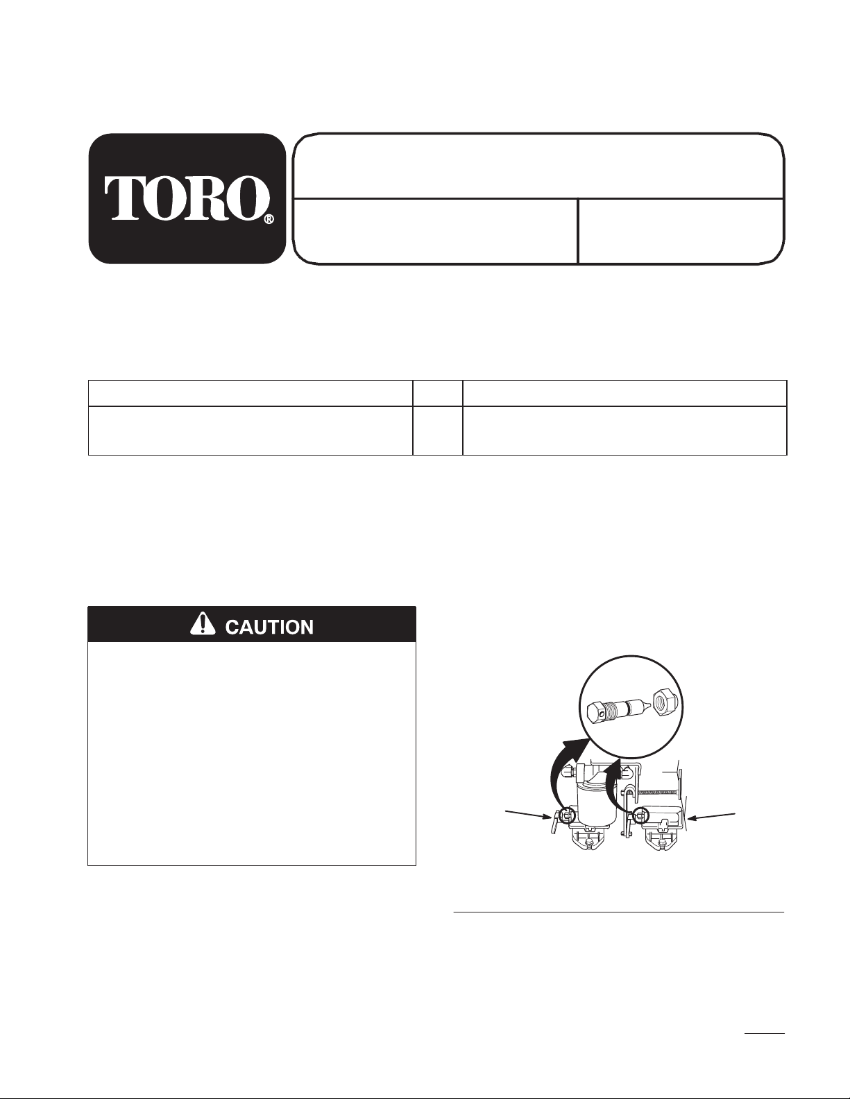
2. Clean area of hydraulic pumps around existing
by-pass valves (Fig. 1).
Valves
3. Loosen jam nuts and unscrew existing by-pass
1. Shut off engine and and wait for all moving parts
to stop. Remove spark plug wire(s).
valves (Fig. 1). Discard valves.
Note: Place a rag under valve area as a small
amount a hydraulic fluid may run out
of opening.
INSTALLATION
INSTRUCTIONS
POTENTIAL HAZARD
• If you leave the wire on the spark plug,
someone could start the engine.
WHAT CAN HAPPEN
• Accidental starting of engine could
seriously injure you or other bystanders.
HOW TO AVOID THE HAZARD
• Pull wire off spark plug before you do any
maintenance. Also push wire aside so it
does not accidentally contact spark plug.
2
1
Figure 1
1. Hydraulic pump 2. Existing by-pass valve
1
m–3110
1
Page 2
Installation
Install New By-Pass Valve
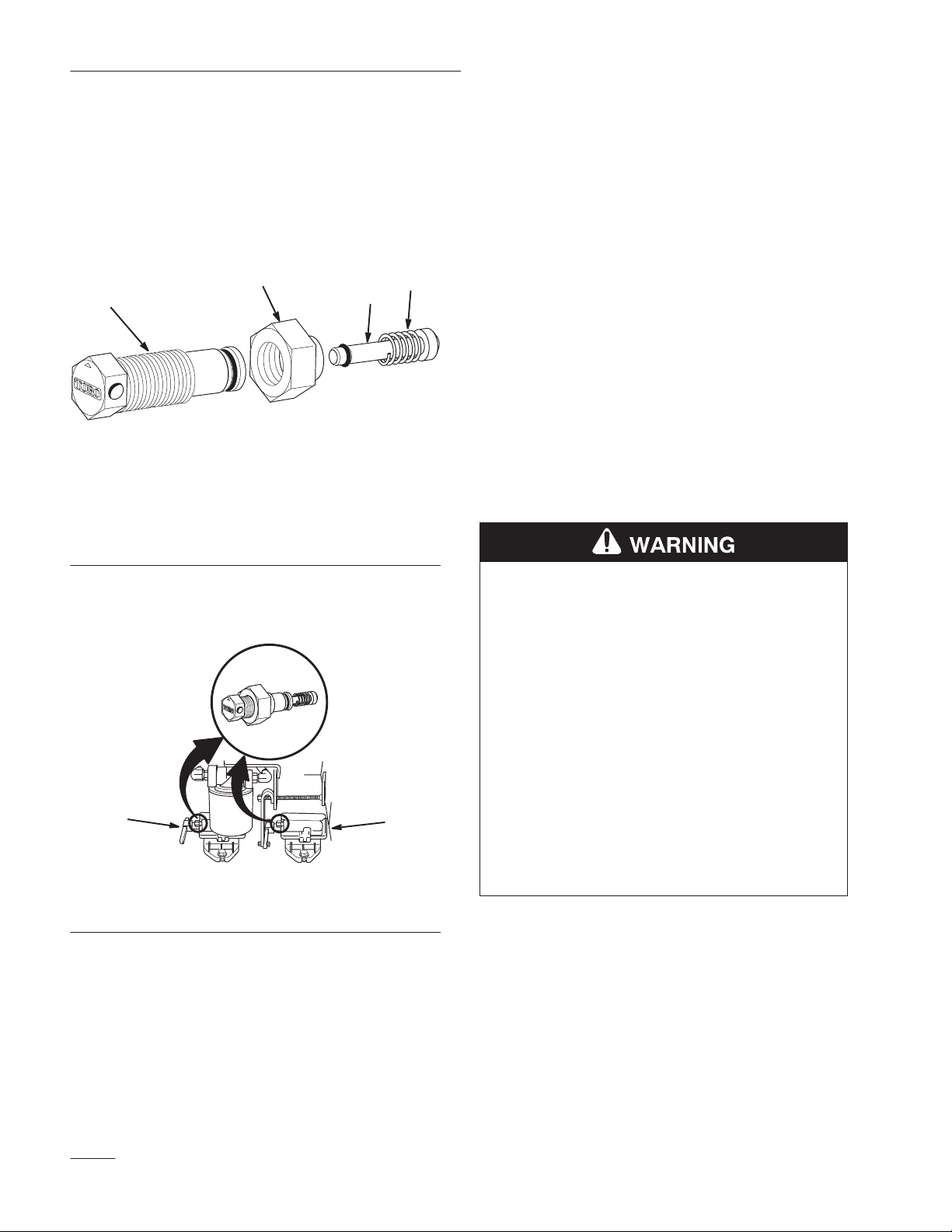
1. Assemble the new by-pass valves, if necessary,
gently rotate and push spring tip into body and
threading jam nut onto body with shoulder
toward tip as shown (Fig. 2).
1
1. Body
2. Tip
3
Figure 2
3. Jam nut
4. Spring
4
2
m–3107
Bleeding Hydraulic System
The traction system is self bleeding, however, it may
be necessary to bleed the system after changing the
valve
1. Raise the rear of machine until wheels are off the
floor and support with jack stands.
2. Start the engine and run at idle speed. Engage
traction on one side and spin the wheel by hand.
3. When the wheel begins to spin on its own, keep
it engaged until wheel drives smoothly.
(minimum 2 minute)
4. Check hydraulic fluid level as it drops and add
as required to maintain level.
5. Repeat procedure on opposite wheel.
2. Thread new by-pass valves into hydraulic pumps
(Fig.3 ).
2
1
Figure 3
1. Hydraulic pump 2. New valve
1
m–3111
POTENTIAL HAZARD
• Hydraulic fluid escaping under pressure
can penetrate skin and cause injury.
WHAT CAN HAPPEN
• Fluid accidentally injected into the skin
must be surgically removed within a few
hours by a doctor familiar with this form of
injury or gangrene may result.
HOW TO AVOID THE HAZARD
• Keep body and hands away from pin hole
leaks or nozzles that eject high pressure
hydraulic fluid.
• Use cardboard or paper to find hydraulic
leaks.
2
Page 3

Installation
Adjusting By-pass Valve
The by–pass valve is adjustable to ensure easy
operation with a variety of deck sizes. If the front of
the deck lifts off the ground when the upper control
bar is quickly pushed forward or the machine is
unable to drive up hills, an adjustment may be
needed.
Test Procedure
1. Start engine and run for 5 minutes at 3/4 throttle,
to warm hydraulic fluid.
2. Drive the machine to a clear and level open area
such as a driveway.
IMPORTANT: There should be at least 10
feet of clear area in front of the machine.
3. Loosen the quick release levers and push the
reference bar forward to the “FAST” position.
Lock the quick release levers to secure the
reference bar.
8. If the machine accelerates slowly, and the front
caster wheels do not lift off the ground, the
machine is too un–responsive. Adjustment is
required.
Adjustment Procedure
The by–pass valve should be adjusted to deliver best
performance for the size (weight) mower you have.
The by–pass valve factory setting is 1/2 turn out.
The following values can be used as initial settings
for different size mowers:
62” 1/6 turn out
52” 1/2 turn out
44” 1 turn out
36” 1 turn out
9. Loosen large jam nut several turns (Fig. 4).
10. Gently close by–pass valve (Fig. 4).
IMPORTANT: Do not over–tighten valve or
needle and seat may be damaged. Do not
exceed 50 inch pounds to close valve.
4. Move throttle control to 3/4 throttle.
5. Quickly push the upper control bar against the
reference bar. The front caster wheels should
almost lift off the ground. If front caster wheels
lift the off the ground , the machine is too
aggressive and adjustment is required.
6. Move the engine throttle to the “FAST” position.
7. Quickly push the upper control bar against the
reference bar. The front caster wheels should lift
1 to 3 inches off the ground. If front caster
wheels lift the off the ground more than 3
inches, the machine is too aggressive.
Adjustment is required.
11. Open by–pass valve 1/2 turn (Fig. 4).
12. Tighten jam nut to lock the adjustment (Fig. 4).
13. Repeat “Test Procedure” to check for proper
operation.
IMPORTANT: By–pass valve adjustment is
very sensitive, do not adjust more than 1/6
turn (one flat) at a time.
14. If the machine is too aggressive, the valve needs
to be open further.
15. If the machine is un–responsive, the valve needs
to be closed further.
3
Page 4

Installation
16. Repeat “Test Procedure” to check for proper
operation. Re-adjust the by–pass valves until
proper performance is achieved.
1
1
Figure 4
1. By-pass valve 2. Jam nut
2
m–3098
Install Decal
1. Install decal for by-pass valve adjustment to rear
frame (Fig. 5).
m–3107
Figure 5
1. Decal
4
 Loading...