

Page 1
FORM NO. 3316-264
PART NO. 92-6020
INSTRUCTIONS
ELECTRIC STARTER MOTOR KIT
INSTALLATION
(For 1990 CCR 1000 Electric Start Snowthrower Model No. 38195)
Since this instruction sheet covers only a small portion of the information necessary to maintain and operate
your snowthrower, we suggest that you keep this material with your Operator's Manual so that both may be re
ferred to for instructions concerning safe operation and proper maintenance procedures.
INSTALLATION INSTRUCTIONS
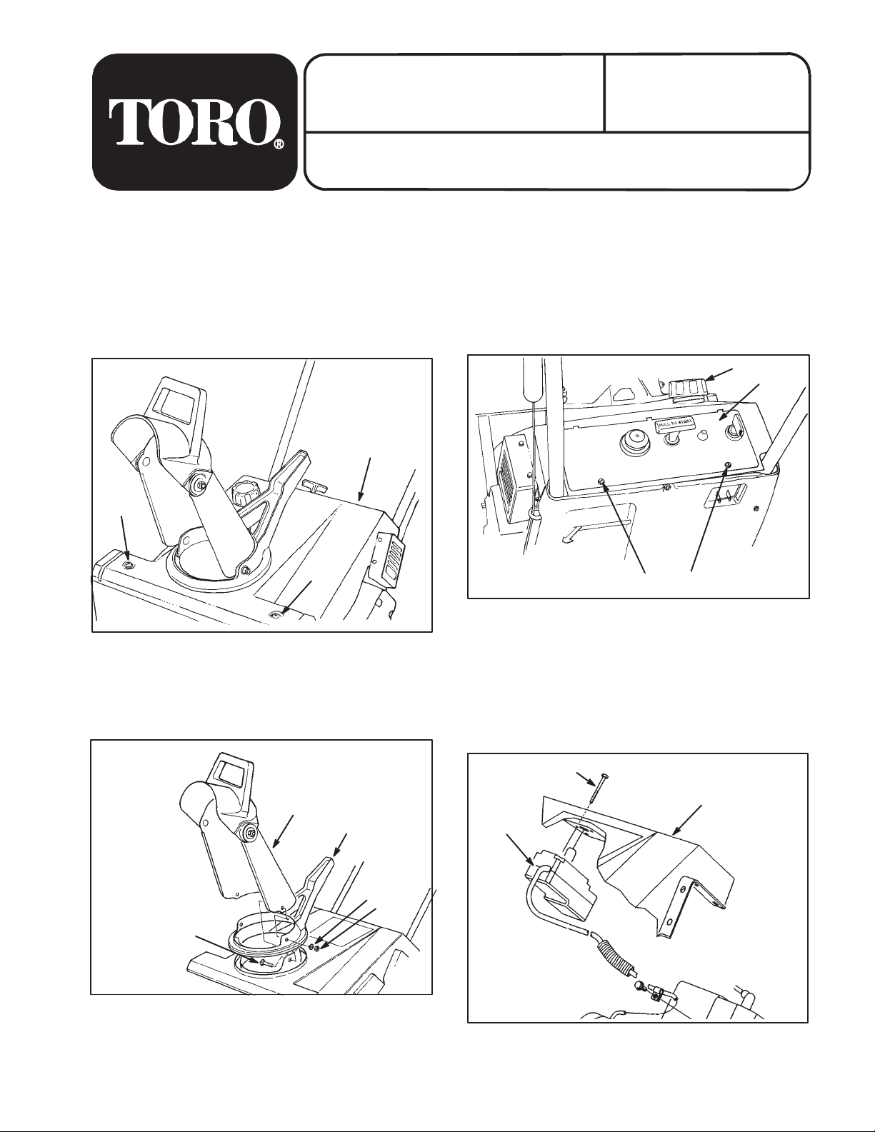
1. Remove (2) two bolts from front of upper shroud
(Fig. 1).
1
3. Remove (2) two screws from control panel
(Fig. 3) and allow panel to hang from recoil rope.
3
1
2
2
Figure 1
1. Upper shroud 2. Bolt (2)
2. Remove (3) three carriage bolts securing dis
charge chute and chute handle to chute ring. Set
chute, handle and fasteners aside.
1
2
3
4
851
2
2
850
Figure 3
1. Control panel 2. Capscrew (2)
3. Gas cap
4. Remove gas cap (Fig. 3) and save.
5. Tilt front of shroud up toward handle.
6. Remove (3) three screws securing switch assem
bly to upper shroud (Fig. 4). Save screws for later
reinstallation.
2
3
1
5
1. Discharge chute
2. Chute handle
3. Washer
Figure 2
4. Locknut
5. Carriage bolt
The Toro Company-1993
849
1. Switch assembly 2. Screw (3)
All Rights Reserved
852
Figure 4
3. Upper shroud
TPS
Page 2
INSTALLATION INSTRUCTIONS
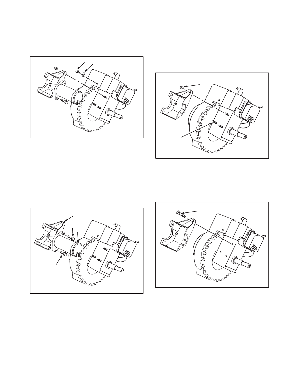
7. Remove screw and rclamp (Fig. 5) and save for
reinstallation.
1
2
856
Figure 5
2. R-clamp1. Screw
8. Remove (2) two screws securing starter motor to
motor mounting bracket (Fig. 6). Discard motor and
(2) two screws.
9. Remove (3) three fasteners securing motor
mounting bracket to engine.
A If bracket was secured to engine with studs
and nuts (Fig. 7), remove (3) three nuts and
bracket. Then remove right hand stud (nearest
to flywheel) (Fig. 7) using a vise grip.
1
2
908
Figure 7
1. Nut 2. Remove right hand stud
B If bracket was secured to engine with (3) three
screws (Fig. 8), remove screws and bracket.
1
3
2
3
1. Motor mounting bracket
2. Starter motor
Figure 6
1
909
856
Figure 8
1. Screw
3. Screw (2)
10. Discard old motor mounting bracket.
2
Page 3

INSTALLATION INSTRUCTIONS
11. Install new motor mounting bracket (Fig. 9) with
correct fasteners. For units with studs, you will need
(2) two new /20 nuts and a screw provided in kit.
For units without studs, you will need (3) three new
/20 screws provided in kit.
1
910
Figure 9
1. New motor mounting bracket
12. Before installing new motor, route electrical wir
ing under motor as shown in Figure 10.
14. Fasten wiring cable to engine with R-clamp and
screw (Fig. 10), making sure wire routing clears the
flywheel.
15. Attach new switch assembly using screws re
moved from old switch assembly (Fig. 11).
2
3
1
852
Figure 11
1. Switch assembly 2. Screw (3)
3. Upper shroud
16. Using a sharp knife, trim inside rib of shroud to
height of /" and length of 1.00" as shown in
Figure 12.
3
4
1
2
5
911
Figure 10
1. Electrical wiring
2. Boss on motor end
3. Rclamp
4. Screw
5. Flywheel
13. Slide boss on right end of motor (Fig. 10) into
hole in bracket and then seat left side of motor onto
bracket. Secure motor with (2) two screws.
3/8"
1
1.00"
859
Figure 12
1. Trim rib to / inch height and 1.00 inch length
17. Reinstall shroud, control panel, discharge chute
and gas cap.
3
Page 4
OPERATING INSTRUCTIONS
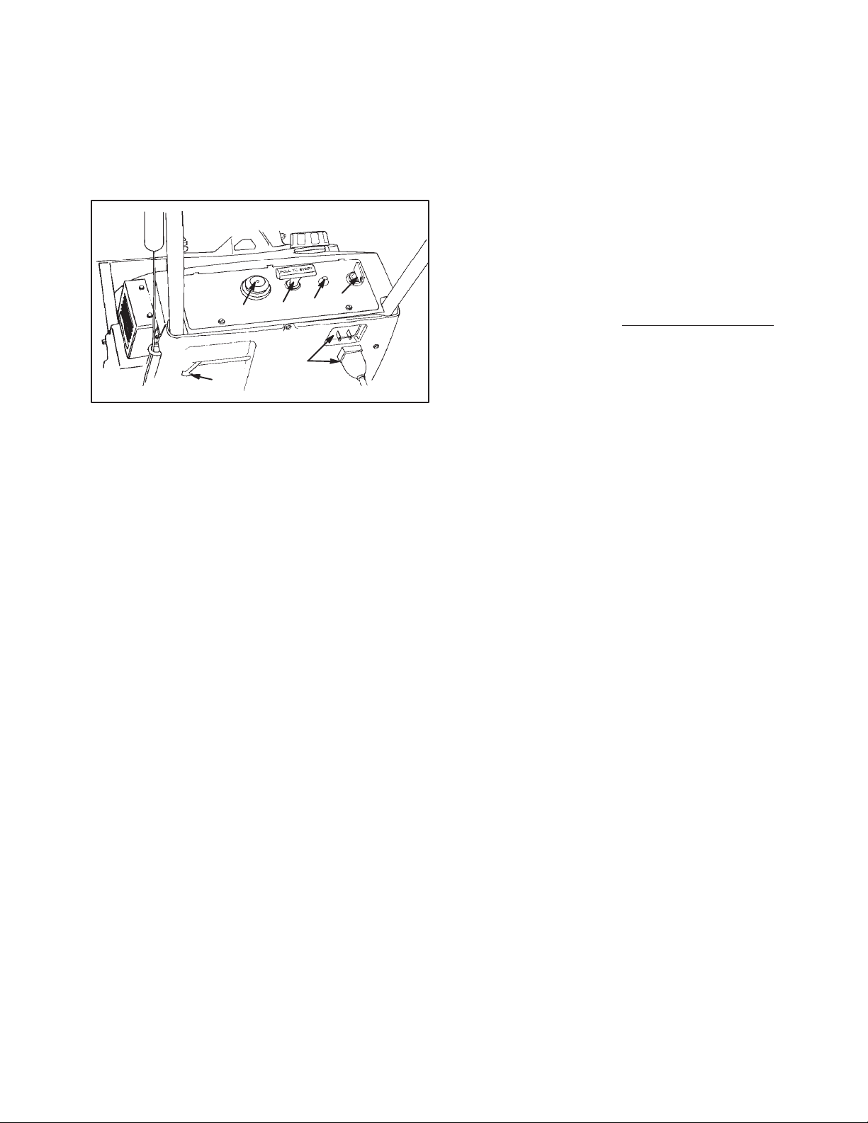
STARTING/STOPPING ENGINE (Fig. 13)
1. CONTROLSKey switch, primer, electric start
button, and recoil starter are located on the control
panel. The choke lever is just below the lower left
corner of the control panel.
1
5
3
2
6
4
Figure 13
1. Key switch
2. Primer
3. Recoil start
4. Choke
5. Elec. start button*
6. Cord connection*
*ELEC. START MODEL
2. Turn key to ON and move choke lever to ON (far
right position).
3. Cover hole in center of primer with thumb and
push primer twice slowly (1 to 2 seconds per prime)
for temperatures above 0F (-18C). Push primer
slowly three times for temperatures below 0F
(-18C). DO NO NOT PRIME IF THE ENGINE HAS
BEEN RUNNING AND IS HOT
898
4a. RECOIL STARTINGHold snowthrower with one
hand and pull recoil starter vigorously with other
hand. If engine does not start after three pulls, push
primer once more and pull recoil starter vigorously
again.
4b. ELECTRIC STARTINGConnect extension cord
to snowthrower and standard household power out
let. Push starter button. When engine starts, discon
nect extension cord from snowthrower and outlet.
IMPORTANT: Excessive running of the electric
starter could damage the starter due to overheat
ing. If you are having difficulty starting the engine,
ONLY TRY THIS STARTING PROCEDURE TWICE.
Run the electric starter no more than 10 times at
intervals of 5 seconds ON, 5 seconds OFF. Make
sure starter motor rotation stops completely be
tween each attempt. If engine does not start after
trying this starting procedure once, wait more
than 40 minutes to allow starter to cool before
trying to run starter again. Before repeating en
gine starting procedure, check that ignition key
switch is ON, and make sure there is fresh fuel in
fuel tank. If engine still will not start after a sec
ond attempt, bring the snowthrower to an Autho
rized Toro Service Dealer for servicing.
5. When engine starts, move choke lever to middle
position after a few seconds of running time. After
engine has warmed up, move choke lever to OFF
(far left) position.
6. TO START/STOP ROTORTo start rotor,
squeeze control bar to handle. When the control bar
handle is released, the rotor blades stop, but the en
gine continues to run.
Note: When starting engine for first time or after run
ning out of fuel, more priming may be required to
start engine.
7. TO STOP ENGINERelease control bar to stop
rotor, turn key to OFF, and wait for all moving parts to
stop before leaving operator's position.
4
 Loading...