

Page 1
Preface
This publications provides the service technician with
information for troubleshooting, testing, and repair of the
Hydroject. Additional information is available in the
Hydroject 3000/4000 Troubleshooting Guide, Part
No. 97928SL
REFER TO THE HYDROJECT OPERATOR’S MANUAL FOR OPERATING, MAINTENANCE AND ADJUSTMENT INSTRUCTIONS. Space is provided in
Chapter 2 of this book to insert the Operator ’s Manual
and Parts Catalog for your machine. A replacement
Operator’s Manual is available by sending the complete
Model and Serial Number of the machine to:
The Toro Company
8111 Lyndale Avenue South
Bloomington, MN 55420
The T oro Company reserves the right to change product
specifications or this publication without notice.
.
Part No. 91764SL Rev. C
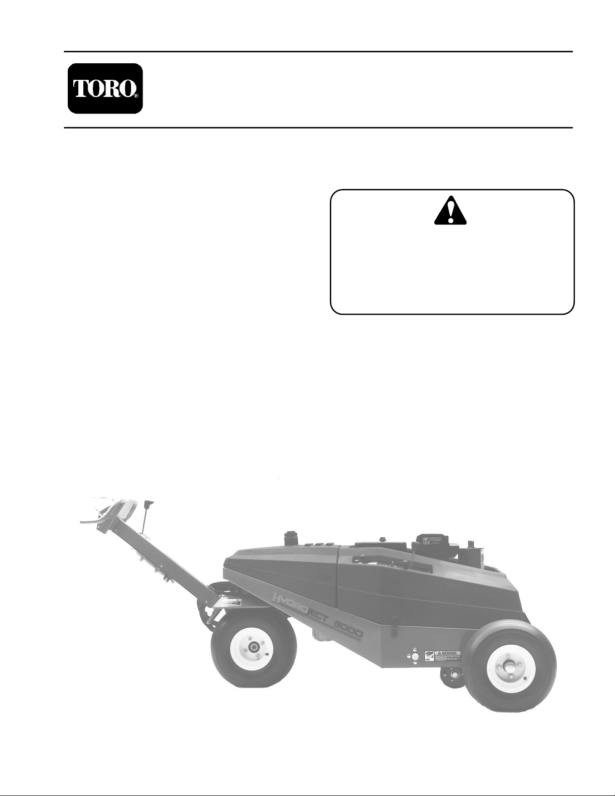
Service Manual
Hydroject ® 3000/4000
means DANGER,Th is safety symbol
WARNING, or CAUTION, PERSONAL SAFETY
INSTRUCTION. When you see this symbol,
carefully read the instructions that follow.
Failure to obey the instructions may result in
personal injury.
NOTE: A NOTE will give general information about the
correct operation, maintenance, service, testing or repair of the machine.
IMPORTANT: The IMPORTANT notice will give important instructions which must be followed to prevent damage to systems or components on the
machine.
©
The Toro Company 1991-1997
Page 2

Hydroject 3000/4000
Page 3

Table Of Contents
Chapter 1 - Safety
Safety Instructions . . . . . . . . . . . . . . . . . . . . . . . . 1 - 1
Safety and Instruction Decals
Chapter 2 - Product Records and Manuals
Product Records. . . . . . . . . . . . . . . . . . . . . . . . . . 2 - 1
Equivalents and Conversions
Torque Specifications
Lubrication
Equipment Operation and Service History Forms 2 - 5
Chapter 3 - Engine
Specifications . . . . . . . . . . . . . . . . . . . . . . . . . . . . 3 - 1
Repairs . . . . . . . . . . . . . . . . . . . . . . . . . . . . . . . . . 3 - 2
Onan Engine Service Manual
Chapter 4 - Hydraulic System
Specifications . . . . . . . . . . . . . . . . . . . . . . . . . . . . 4 - 2
General Information
Hydraulic Diagram
Special Tools . . . . . . . . . . . . . . . . . . . . . . . . . . . . 4 - 7
Troubleshooting
Testing . . . . . . . . . . . . . . . . . . . . . . . . . . . . . . . . . 4 - 9
Adjustments
Repairs
. . . . . . . . . . . . . . . . . . . . . . . . . . . . . . 2 - 4
. . . . . . . . . . . . . . . . . . . . . . . . . . . . 4 - 11
. . . . . . . . . . . . . . . . . . . . . . . . . . . . . . . . 4 - 14
. . . . . . . . . . . . . . . . . . . . . . 2 - 3
. . . . . . . . . . . . . . . . . . . . . . . 4 - 3
. . . . . . . . . . . . . . . . . . . . . . . . 4 - 6
. . . . . . . . . . . . . . . . . . . . . . . . . . 4 - 8
. . . . . . . . . . . . . . . . 1 - 4
. . . . . . . . . . . . . . . . 2 - 2
Chapter 5 - Electrical System
Wiring Schematics and Diagrams. . . . . . . . . . . . . 5 - 2
Special Tools
Troubleshooting . . . . . . . . . . . . . . . . . . . . . . . . . . 5 - 9
Testing . . . . . . . . . . . . . . . . . . . . . . . . . . . . . . . . 5 - 17
Repairs
Chapter 6 - Water System
Specifications . . . . . . . . . . . . . . . . . . . . . . . . . . . . 6 - 2
Water System Schematic
Special Tools
Troubleshooting . . . . . . . . . . . . . . . . . . . . . . . . . . 6 - 9
Testing . . . . . . . . . . . . . . . . . . . . . . . . . . . . . . . . 6 - 12
Adjustments
Repairs . . . . . . . . . . . . . . . . . . . . . . . . . . . . . . . . 6 - 20
Chapter 7 - Wheels, Steering and Brakes
Adjustments . . . . . . . . . . . . . . . . . . . . . . . . . . . . . 7 - 2
Repairs
Chapter 8 - Hydroject 4000 Addendum
Safety and Instruction Decals . . . . . . . . . . . . . . . . 8 - 2
Specifications . . . . . . . . . . . . . . . . . . . . . . . . . . . . 8 - 3
Maintenance Schedule
Electrical Schematic
Water System Diagram. . . . . . . . . . . . . . . . . . . . 8 - 13
Service and Repairs
. . . . . . . . . . . . . . . . . . . . . . . . . . . . . 5 - 7
. . . . . . . . . . . . . . . . . . . . . . . . . . . . . . . . 5 - 26
. . . . . . . . . . . . . . . . . . . 6 - 3
. . . . . . . . . . . . . . . . . . . . . . . . . . . . . 6 - 4
. . . . . . . . . . . . . . . . . . . . . . . . . . . . 6 - 18
. . . . . . . . . . . . . . . . . . . . . . . . . . . . . . . . . 7 - 3
. . . . . . . . . . . . . . . . . . . . . 8 - 7
. . . . . . . . . . . . . . . . . . . . . . 8 - 11
. . . . . . . . . . . . . . . . . . . . . . 8 - 14
Hydroject 3000/4000
Rev. B
Page 4

Hydroject 3000/4000
Page 5
Table of Contents
Chapter 1
Safety
SAFETY INSTRUCTIONS . . . . . . . . . . . . . . . . . . . . . . 1
Before Operating . . . . . . . . . . . . . . . . . . . . . . . . . . . . 1
While Operating . . . . . . . . . . . . . . . . . . . . . . . . . . . . . 2
Safety Instructions
Although hazard control and accident prevention partially are dependent upon the design and configuration
of the machine, these factors are also dependent upon
the awareness, concern, and proper training of the per
sonnel involved in the operation, transport, maintenance, and storage of the machine. Improper use or
maintenance of the machine can result in injury or
death. T o reduce the potential for injury or death, comply
with the following safety instructions.
Before Operating
1. Read and understand the contents of this manual
before starting and operating the machine. Become fa
miliar with all controls and know how to stop quickly. A
free replacement manual is available by sending com
plete Model and Serial Numbers to:
The Toro Company
8111 Lyndale Avenue South
Bloomington, Minnesota 55420
Use the Model and Serial Number when referring to your
machine. If you have questions about this Service
Manual, please contact:
The Toro Company
Commercial Service Department
8111 Lyndale Avenue South
Bloomington, Minnesota 55420
2. Never allow children to operate the machine. Do not
allow adults to operate machine without proper instruc
tion. Only trained operators who have read this manual
should operate this machine.
-
-
-
-
Maintenance and Service . . . . . . . . . . . . . . . . . . . . . 3
SAFETY AND INSTRUCTION DECALS
. . . . . . . . . . 4
CAUTION
TO REDUCE THE POTENTIAL FOR INJURY
OR DEA TH, COMPL Y WITH THE FOLLOWING
SAFETY INSTRUCTIONS.
3. Never operate the machine when under the influ-
ence of drugs or alcohol.
4. Before attempting to start engine engage parking
brake.
5. Remove all debris or other objects that might interfere with operation. Keep all bystanders away from the
work area.
6. Keep all shields and safety devices in place. If a
shield, safety device or decal is defective or damaged,
repair or replace it before operation is commenced. Also
tighten any loose nuts, bolts and screws to assure ma
chine is in safe operating condition.
7. Do not operate machine while wearing sandals, tennis shoes, sneakers or shorts. Also, do not wear loose
fitting clothing which could get caught in moving parts.
Always wear long pants and substantial shoes. Wearing
safety glasses, safety shoes, ear protection and a hel
met is advisable and required by some local ordinances
and insurance regulations.
-
-
Hydroject 3000
Page 1 – 1
Rev. B
Safety
Page 6

8. Fill fuel tank with gasoline before starting the en-
gine. Avoid spilling gasoline. Since gasoline is flammable, handle it carefully.
A. Use an approved gasoline container.
B. Do not fill tank while engine is hot or
running.
C. Do not smoke while handling gasoline.
While Operating
D. Fill fuel tank outdoors and up to about one
inch (25 mm) from top of the tank, not the
filler neck.
E. Wipe up any spilled gasoline.
9. Check interlock switches daily for proper operation.
If a switch fails, replace it before operating the machine.
The interlock system is for your protection, so do not bypass it. Replace all interlock switches every two years.
10. DON’T TAKE AN INJUR Y RISK! When a person or
pet appears unexpectedly in or near the WORKING
area, STOP AERATING.
11. Keep hands and feet away from nozzle and roller
area. High velocity water jets can penetrate hands and
feet. Penetration by the high velocity water jets can
cause serious personal injury. If accidental penetration
occurs, seek medical attention immediately.
12. Never use chemicals in the water supply system.
13. Do not operate water injection system on concrete
or asphalt because water jets will permanently damage
these surfaces.
14. Start engine with parking brake engaged.
15. Do not run the engine in a confined area without ad-
equate ventilation. Exhaust fumes are hazardous and
could possibly be deadly.
16. Using the machine demands attention, and to prevent loss of control:
Maintenance
A. Use only in daylight or when there is good
artificial light.
B. Watch for holes or other hidden hazards.
C. Do not transport machine close to a sand
trap, ditch, creek or other hazard.
17. If the machine starts to vibrate abnormally , shut the
engine off. Remove wires from spark plugs to prevent
possibility of accidental starting. Check machine for
damage and defective parts. Repair any damage before
restarting the engine and operating the machine.
18. Do not touch engine or muffler while engine is running or soon after it is stopped. These areas could be hot
enough to cause a burn.
19. Before leaving the operator’s position–behind handle–engage parking brake.
20. When leaving the machine unattended, engage
parking brake , shut engine OFF and remove key from
ignition switch.
21. Disconnect wires from spark plugs to prevent accidental starting of the engine when servicing, adjusting or
storing the machine.
22. If machine must be tipped to perform maintenance
or an adjustment, close fuel shut–off valve, drain gaso
line from fuel tank, oil from crankcase and remove battery .
23. T o reduce potential fire hazard, keep the engine free
of excessive grease, grass, leaves and accumulations
of dirt.
24. Be sure machine is in safe operating condition by
keeping nuts, bolts and screws tight. Check all bolts and
nuts frequently to be sure they are tightened to specification.
25. If the engine must be running to perform a maintenance adjustment, keep hands, feet, clothing and other
parts of the body away from any moving parts.
26. Make sure all hydraulic line connectors are tight, and
all hydraulic hoses and lines are in good condition be
fore applying pressure to the system.
Safety
Page 1 – 2 Rev. B
27. Keep body and hands away from pin hole leaks or
nozzles that eject water or hydraulic fluid under high
pressure. Use paper or cardboard, not hands, to search
for leaks. Hydraulic fluid or water escaping under pres
sure can have sufficient force to penetrate skin and do
serious damage. If either of these fluids are ejected into
the skin they must be surgically removed within a few
hours by a doctor familiar with this form of injury or gan
grene may result.
28. Before disconnecting or performing any work on the
hydraulic oil system, all pressure in system must be re
lieved by stopping engine and opening by–pass valve.
29. Make sure all water line connectors are tight, and all
hoses and lines are in good condition before applying
pressure to the system.
-
Hydroject 3000
-
-
-
Page 7

30. Before disconnecting or performing any work on the
water system, all pressure in system must be relieved by
stopping engine and opening bleed valve. Opening the
the bleed valve allows any trapped water to escape from
the system and also allows the accumulator piston to
move to the bottom of the accumulator cylinder.
31. The accumulator in this machine contains high
pressure dry nitrogen. Accumulator servicing requires
special tools and precautions. Accumulators do not contain user serviceable components. Improper accumulator servicing can cause dismemberment or death. Do
not attempt to disassemble a accumulator, have this
work done by a Authorized Toro Distributor.
32. Do not overspeed the engine by changing governor
settings. T o be sure of safety and accuracy , have an Au
thorized T0R0 Distributor check maximum engine
speed with a tachometer.
33. Engine must be shut off before checking oil or adding oil to the crankcase.
-
34. Allow engine to cool before storing machine in any
enclosure such as a garage or storage shed. Make sure
the fuel tank is empty if machine is to be stored in excess
of 30 days. Do not store machine near any open flame or
where gasoline fumes may be ignited by a spark. Always
store gasoline in a safety approved, red metal container.
35. When storing or transporting machine (trailering),
make sure fuel shut–off valve is closed.
36. Perform only those maintenance instructions described in this manual. If major repairs are ever needed
or assistance is desired, contact an Authorized T oro Dis
tributor. To ensure optimum performance and safety , always purchase genuine TORO replacement parts and
accessories to keep the Toro all TORO. NEVER USE
“WILL–FIT” REPLACEMENT P ARTS AND ACCESSORIES MADE BY OTHER MANUFACTURERS. Look for
the TORO logo to assure genuineness. Using unap
proved replacement parts and accessories could void
the warranty of The Toro Company.
-
-
Hydroject 3000
Page 1 – 3
Rev. B
Safety
Page 8
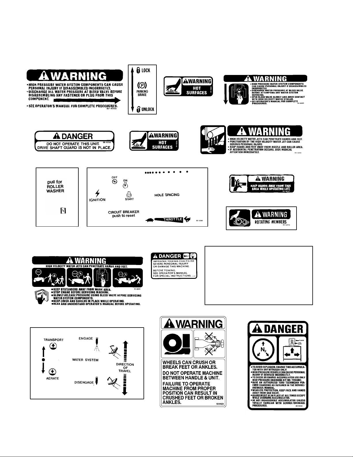
Safety and Instruction Decals
The following decals are installed on the machine. If any become damaged or illegible, replace it. The decal part number is listed below and in your parts catalog. Replacement can be ordered from your Authorized T oro Distributor . Foreign language decal sets are also available from your Authorized Toro Distributor.
On Each Side Of Engine (2)
On Drive Shaft Shield
(Part No. 80–8000)
(Part No. 80–9350)
On Top Of Tiller Arm
(Part No. 80–8070)
On Accumulator body
(Part No. 80–8880)
On Trans. Pump Bracket – under shield
(Part No. 80–8760)
On Control Panel
(Part No. 80–8150)
On Underside of Tiller Control Panel
(Part No. 80–8020)
On Muffler Shield (3)
(Part No. 80–8290)
On Control Panel
(Part No. 80–8110)
On Wheel Motor Fork
(Part No. 72–4080)
On Sides and Behind Rollers (3
(Part No. 80–8090)
On Lift Actuator
(Part No. 80–8010)
On Drive Shaft Guard
(Part No. 80–8040)
IMPORTANT
THE FIVE MICRON FILTER ELEMENT (86–8620) MUST
D
BE IN PLACE AT ALL TIMES.
OPERATION WITHOUT PROPER FILTRATION WILL
D
RESULT IN PREMATURE WEAR AND FAILURE OF THE
WATER SYSTEM COMPONENTS.
DUSE OF ADDITIONAL FILTRATION OR POTABLE WATER
MAY BE NECESSARY TO PROLONG THE LIFE OF THE
FILTRATION SYSTEM.
DSEE OPERATOR’S MANUAL FOR MORE INFORMATION.
On Each Side Of Machine (2)
(Part No. 92–9542)
Safety
On Tiller Control Panel
(Part No. 80–9240)
On Tiller Arm
(Part No. 93–9429)
Page 1 – 4 Rev. B
On Accumulator body
(Part No. 80–8030)
Hydroject 3000
Page 9

Product Records and Maintenance
Table of Contents
Chapter 2
PRODUCT RECORDS . . . . . . . . . . . . . . . . . . . . . . . . . 1
EQUIVALENTS AND CONVERSIONS 2
Decimal and Millimeter Equivalents 2
U.S. to Metric Conversions . . . . . . . . . . . . . . . . . . . 2
. . . . . . . . . . .
. . . . . . . . . . . .
Product Records
Record information about your Hydroject 3000 on the
OPERATION AND SERVICE HISTORY REPORT
form. Use this information when referring to your
machine.
. .
3
3
.
3
4
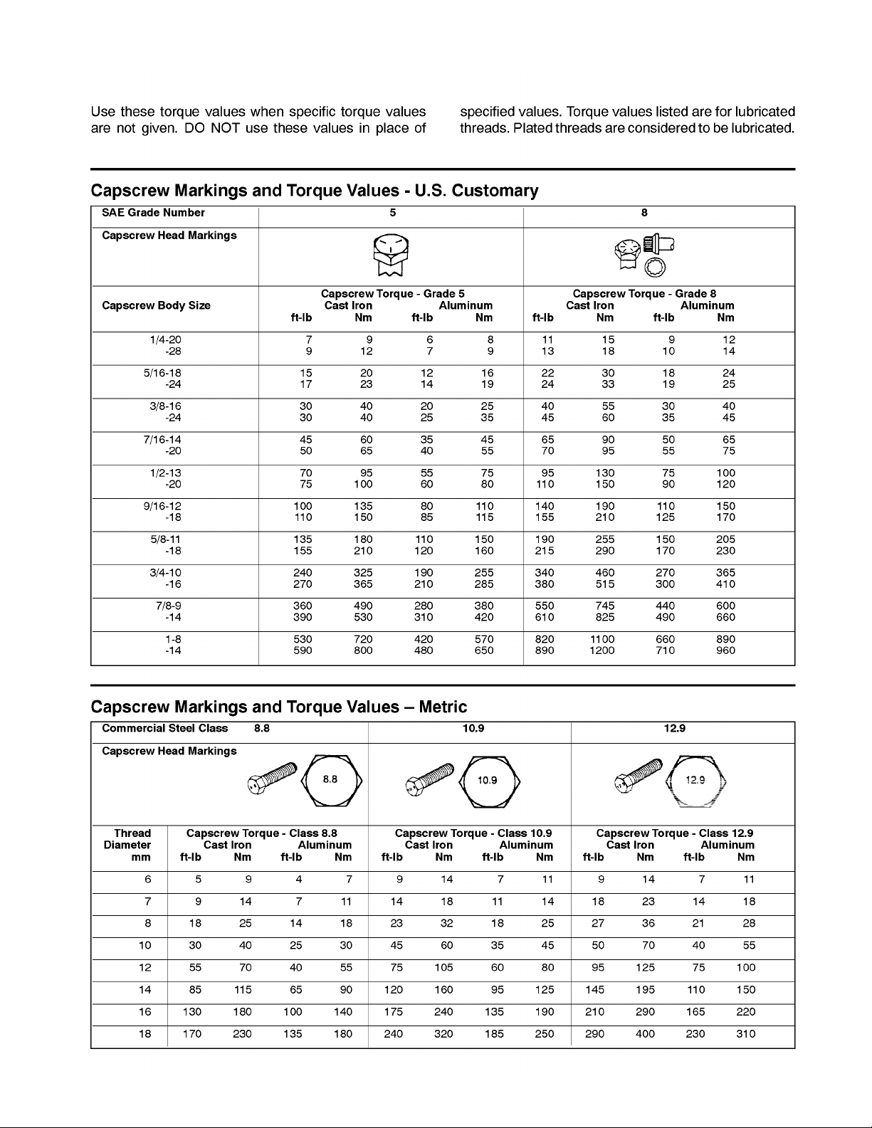
TORQUE SPECIFICATIONS . . . . . . . . . . . . . . . . . . .
Capscrew Markings and Torque Values – U.S.
Capscrew Markings and Torque Values – Metric
LUBRICATION . . . . . . . . . . . . . . . . . . . . . . . . . . . . . . . .
OPERATION AND SERVICE HISTORY REPORTS 5
Insert Operator’s Manuals and Parts Catalogs for your
Hydroject 3000 at the end of this section.
Hydroject 3000
Page 2 – 1
Rev. B
Product Records and Maintenance
Page 10
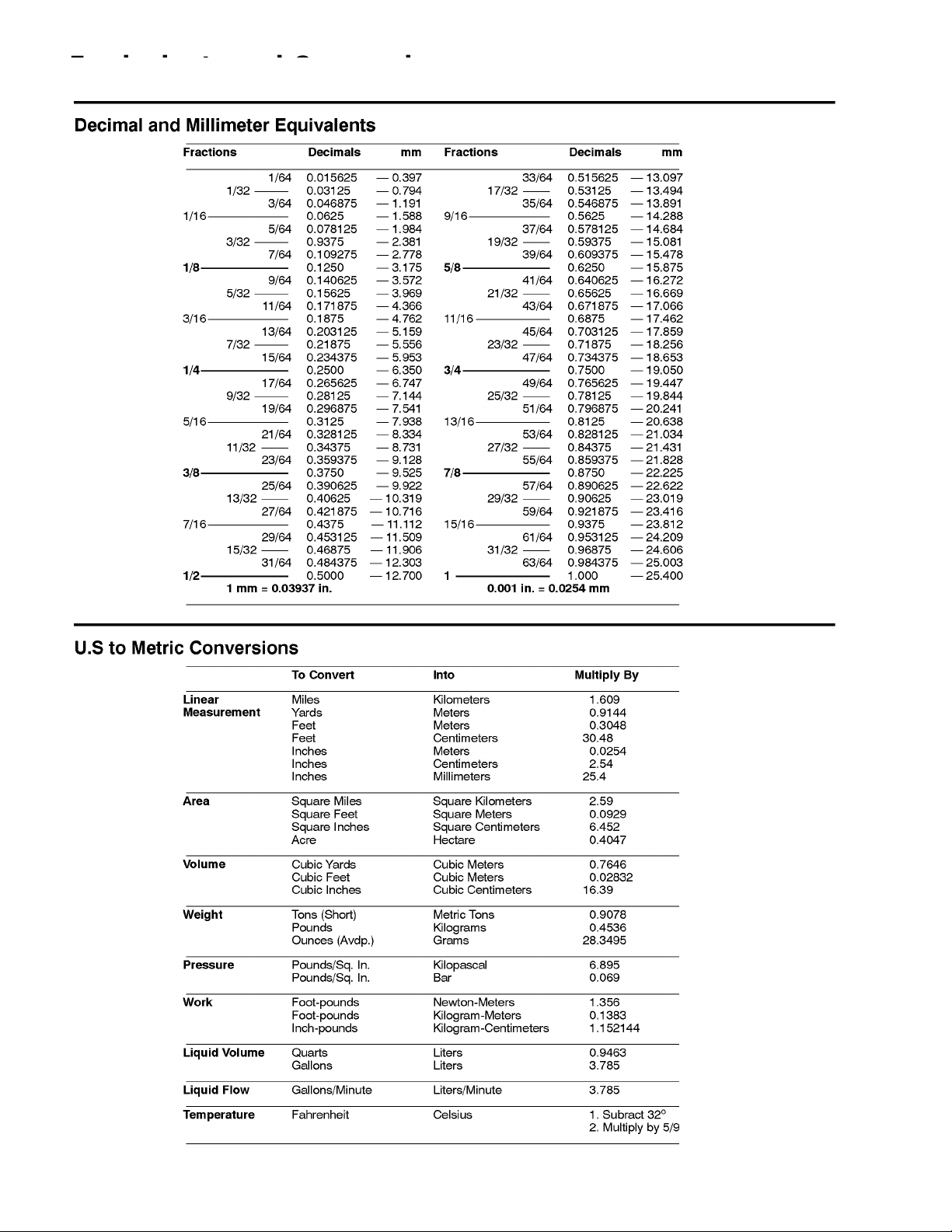
Equivalents and Conversions
Product Records and Maintenance
Page 2 – 2
Hydroject 3000
Page 11
Torque Specifications
Hydroject 3000 Product Records and Maintenance
Page 2 – 3
Page 12
Lubrication
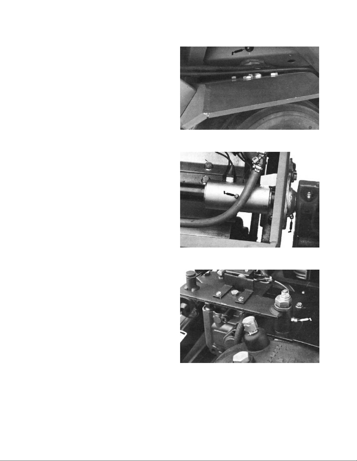
The Hydroject 3000 has 5 grease fittings that must be
lubricated every 50 hours of operation with No. 2 Gener
al Purpose Lithium Base Grease. Lubricate all fittings
immediately after every washing, regardless of interval
listed.
The bearings and bushings that must be Iubricated are
the steering pivot shaft (Fig. 1), limit switch housing (2)
on lift arm shaft (Fig. 2) and neutral pivot shaft (Fig. 3).
1. Wipe grease fitting clean so foreign matter cannot
be forced into the bearing or bushing.
2. Pump grease into the bearing or bushing.
3. Wipe up excess grease.
-
Figure 1
Figure 2
Figure 3
Product Records and Maintenance
Page 2 – 4
Rev. B
Hydroject 3000
Page 13

EQUIPMENT OPERATION AND SERVICE HISTORY REPORT
for
HYDROJECTR 3000
TORO Model and Serial Number: ______________–______________
Engine Numbers: _____________________________
Transmission Numbers: _____________________________
Drive Axle(s) Numbers: _____________________________
Date Purchased: _____________________________ Warranty Expires____________
Purchased From: _____________________________
_____________________________
_____________________________
Contacts: Parts _____________________________ Phone____________________
Service _____________________________ Phone____________________
Hydroject 3000
Sales _____________________________ Phone____________________
Page 2 – 5
Rev. B
Product Records and Maintenance
Page 14
Hydroject 3000 Maintenance Schedule
Minimum Recommended Maintenance Intervals
Maintenance Procedure
Check Battery Fluid Level
Check Battery Cable Connections
Lubricate All Grease Fittings
{ Change Engine Oil
{ Change Engine Oil Filter
Change Engine Pre–cleaner (Air Filter)
Replace Air Filter Element
Replace Fuel Filter
Adjust Water System Cam–Valve Clearance
Clean Engine Crankcase Breather
{ Change Gear Case Oil and Filter
{ Change Pump Case Oil
Torque Wheel Lug Nuts
{
Service Accumulator
Adjust Parking Brake
Calibrate Aeration Traction Speed
Service Injector Nozzles and Springs
Replace Spark Plugs
Decarbon Combustion Chambers
Torque Head and Adjust Valves
}
} Check Engine RPM (idle and full throttle)
Maintenance Interval & Service
Every
400hrs
D Service
Every
50hrs
A Service
Every
100hrs
B Service
Every
200hrs
C Service
{ Initial break in at 25 hours
} Initial break in at 50 hours
Replace Moving Hoses
Replace Safety Switches
Fuel Tank – Drain/Flush
Hydraulic Tank – Drain/Flush
Annual Recommendations:
Items listed are recommended every 1000
hours or 2 years, whichever occurs first.
(See Operator’s and Service Manual for specifications and procedures)
Product Records and Maintenance
Page 2 – 6
Rev. B
Hydroject 3000
Page 15

Hydroject 3000 Daily Maintenance Check List
Maintenance
Check Item b
n Safety Interlock Operation
n Brake Operation
n Engine Oil Level
n Engine Air Filter Pre–Cleaner
n Engine Cooling FIns for
Daily Maintenance Check For Week Of _________________
MON TUES WED THURS FRI SAT SUN
Debris
n Unusual Engine Noises
n Unusual Operating Noises
n Water Filter/Pressure
n Water Prefilter
n Gear Case Oil Level
n Pump Case Oil Level
n Hydraulic Hose for Damages
n Fluid Leaks
n Tire Pressure
n Instrument Operations
Lubricate All Grease Fittings
1
Touch–up Damaged Paint
1
= Immediately after every washing, regardless of the interval listed.
Notation for areas of concern: Inspection performed by_____________________________
Item Date Information
1
2
3
4
5
6
7
8
Hydroject 3000
Page 2 – 7
Rev. B
Product Records and Maintenance
Page 16
Date: ________________
C – Service (every 200 hours)
B – Service (every 100 hours)
Replace air filter element
Replace fuel filter
Adjust water system cam–valve clearance
Clean engine crankcase breather
Change gear case oil and filter
Change pump case oil
Change engine oil
Change engine oil filter
Change engine pre–cleaner (air filter)
A – Service Required
_______________________________
_______________________________
_______________________________
Torque wheel lug nuts
_______________________________
_______________________________
A and B – Service Required
_______________________________
_______________________________
_______________________________
Replace Moving Hoses
Replace Safety Switches
Other – Annual Service & Specials
Drain & flush fuel tank
Drain & flush hydraulic tank
_______________________________
_______________________________
A B C D E Other
__________________–__________________
TORO I.D. #: Remarks:
Hydroject 3000 Supervisor Maintenance Work Order
Unit Designation:
(Duplicate this page for routine use.)
Product Records and Maintenance
Service to perform (circle):
A– Service (every 50 hours)
Hours:
Technician:
Check battery fluide level
Check battery cable connections
________________________________
Lubricate all grease fittings
________________________________
________________________________
Page 2 – 8
________________________________
Service accumulator
Adjust parking brake
Calibrate aeration traction speed
Service injector nozzle & springs
D – Service (every 400 hours)
Rev. B
Replace spark plugs
Decarbon combustion chambers
Torque head and adjust valves
Check engine RPM (idle & full throttle)
Hydroject 3000
________________________________
A, B and C – Service Required
________________________________
(See Operator’s and Service Manual for specifications and procedures.)
Page 17

Chapter 3
Engine
Table of Contents
SPECIFICATIONS . . . . . . . . . . . . . . . . . . . . . . . . . . 1
REPAIRS . . . . . . . . . . . . . . . . . . . . . . . . . . . . . . . . . 2
Engine Removal and Installation . . . . . . . . . . . . . 2
ONAN SERVICE MANUAL
Specifications
Item Description
___________________________________________________________________________________________
Make / Designation Onan P224G-I/10999C
________________________________________________________________________________________________________________________________________________________
Displacement 59.7 cu. in.
________________________________________________________________________________________________________________________________________________________
Weight 127 lbs. dry
________________________________________________________________________________________________________________________________________________________
Oil Capacity 3 qt. with filter
________________________________________________________________________________________________________________________________________________________
Oil SAE 30W SF, SG, SF/CC or SG/CC
________________________________________________________________________________________________________________________________________________________
Fuel Unleaded regular gasoline
________________________________________________________________________________________________________________________________________________________
High Idle Speed 3500 ± 50 RPM no load
________________________________________________________________________________________________________________________________________________________
Low Idle Speed 1500 - 1800 RPM
HydroJect™ 3000 Page 3 - 1 Specifications
Page 18
Repairs
30
18
19
23
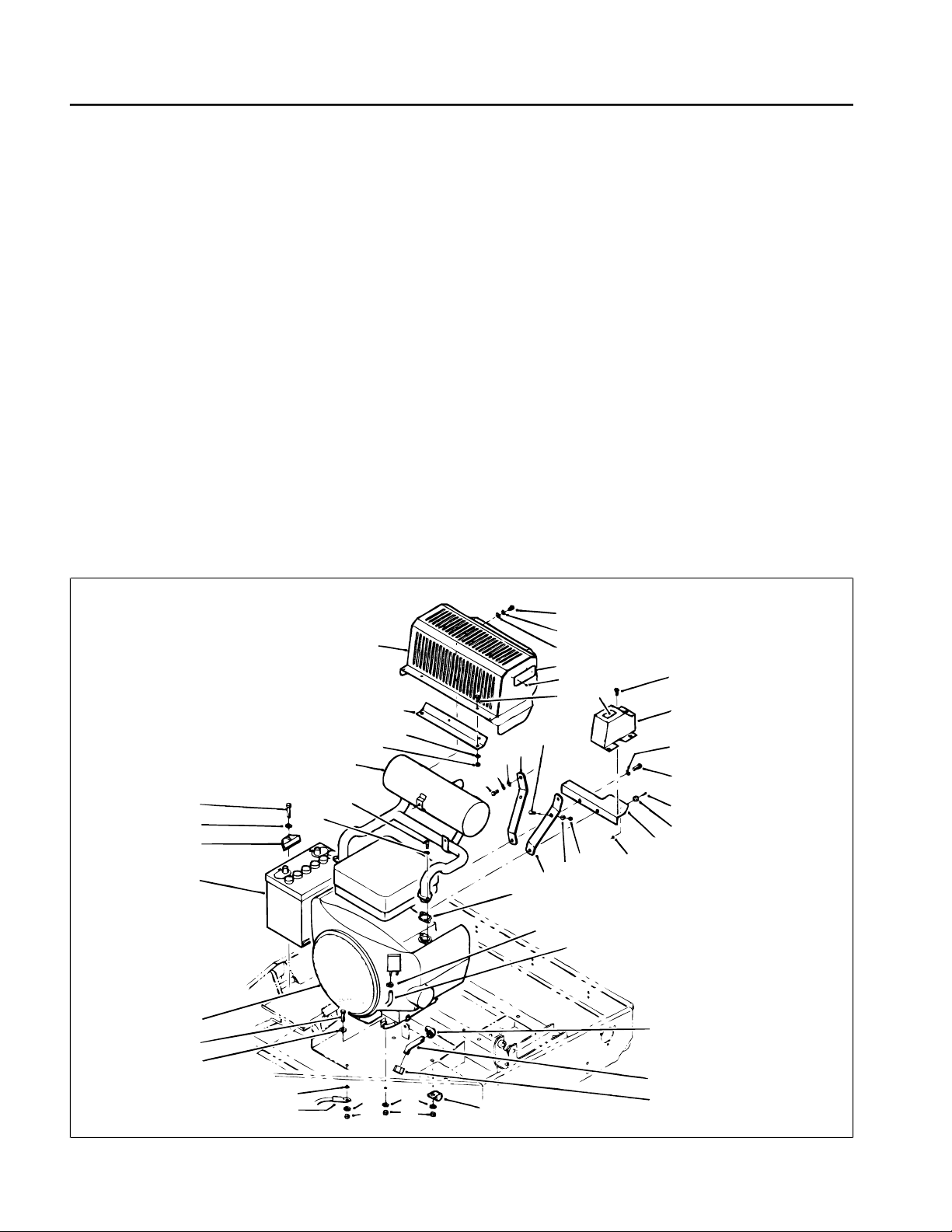
Engine Removal and Installation (Fig. 1)
1. Park the machine on a level surface, engage the
parking brake, and remove the hood.
2. Disconnect both the positive (+) and negative (–)
cables from the battery. Loosen the battery clamp
(Item 2) and remove the battery (Item 1).
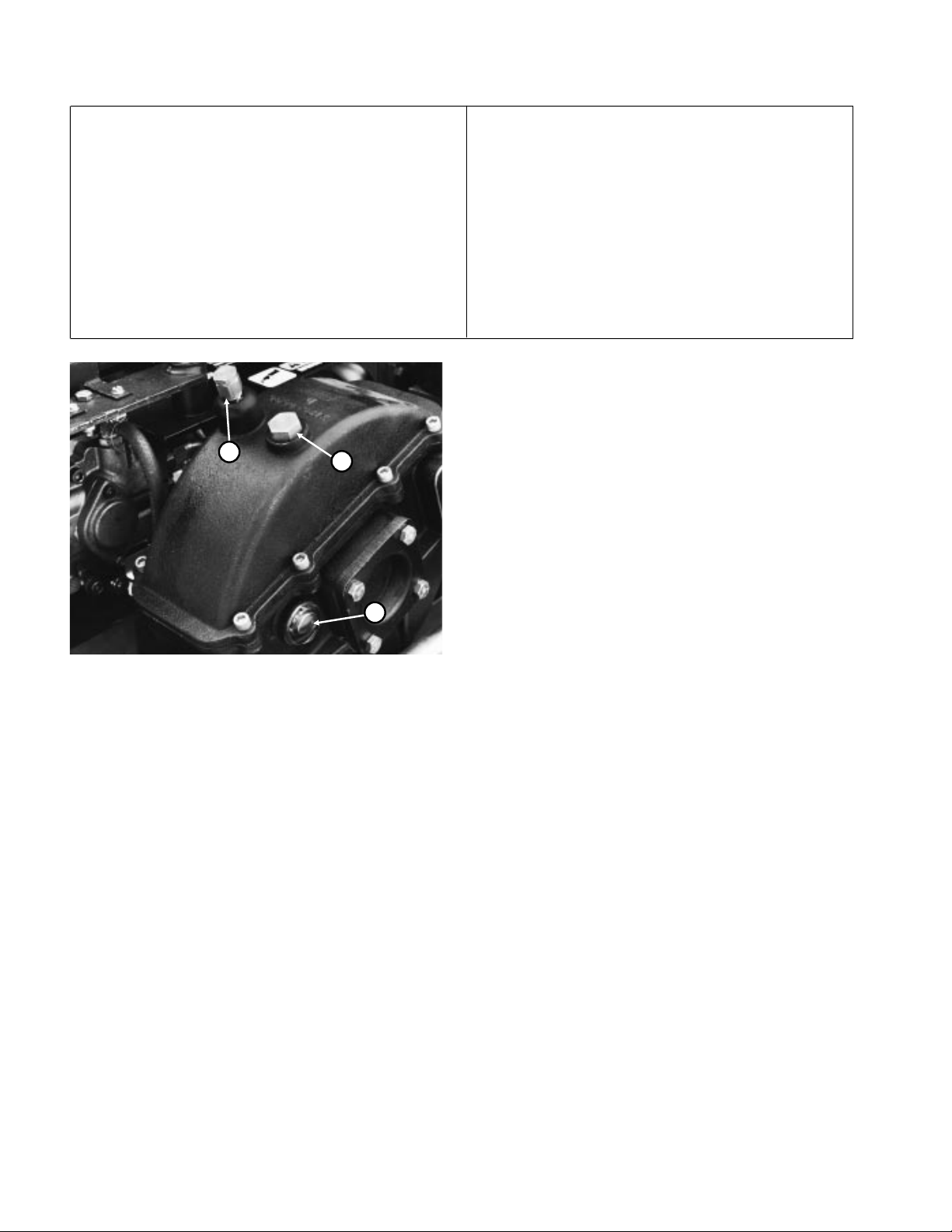
3. Remove the drain cap (Item 33) and let the oil drain
into a container. Clean and install the drain cap.
4. Disconnect the drive coupl ing from the clutch a dapter
(see Drive Coupling Removal and I nstallation in Water
System Service).
5. Remove the water pump drive belt and hydraulic
pump drive belt.
6. Disconnect the engine wiring harness connector.
Disconnect and plug the fuel hose (Item 30).
7. Remove four nuts (Item 35), washers (Item 3), capscrews (Item 39) and spacers (Item 38) securing the
engine to the frame.
11
10
9
8
7
4
3
2
1
6
5
8. Attach an engine lifting chain to the engine lifting
straps. Connect the cha in to a ho is t or b loc k and tackle
and remove slack from the chai n and lifting device. One
person should operate the hoist or block and tackle and
the other person should help guide the engine out of the
frame. Remove the engine from the frame.
9. Mount the engine in an engine rebuilding stand or put
it on a sturdy workbench. Before disassembling the
engine, remove external accessories, such as the muf fler guard (Item 11), muffler (Item 7), hydraulic pump
clutch, hydraulic pump pulle y, water pump clutch and
clutch key (see Drive Coupling Re moval and Installation
in Water System Service).
10. To install the engine, perform steps 2 - 9 in reverse
order. Make sure the ground cable (Item 36) is connected to the frame with an engine mounting nut.
11. Replace the oil filter and fill the engine with the
correct oil.
13
5
12
17
14
15
16
16
18
12
5
8
9
28
27
26
20
21
22
24
25
29
40
39
38
37
36
3
35
3
35
34
31
32
33
Figure 1
Repairs Page 3 - 2 HydroJect
™
3000
Page 19

Table of Contents
Chapter 4
Hydraulic System
SPECIFICATIONS . . . . . . . . . . . . . . . . . . . . . . . . . . 2
GENERAL INFORMATION. . . . . . . . . . . . . . . . . . . . 3
Hydraulic Hose and Fitting Information . . . . . . . . 3
Pushing or Towing . . . . . . . . . . . . . . . . . . . . . . . . 5
HYDRAULIC DIAGRAM. . . . . . . . . . . . . . . . . . . . . . 6
SPECIAL TOOLS . . . . . . . . . . . . . . . . . . . . . . . . . . . 7
Hydraulic Tester. . . . . . . . . . . . . . . . . . . . . . . . . . 7
TROUBLESHOOTING . . . . . . . . . . . . . . . . . . . . . . . 8
Transmission Operates in One Direction Only . . 8
System Operates Hot, Looses Power or
Will Not Operate in Either Direction
TESTING . . . . . . . . . . . . . . . . . . . . . . . . . . . . . . . . . 9
Hydraulic Tests . . . . . . . . . . . . . . . . . . . . . . . . . 10
ADJUSTMENTS . . . . . . . . . . . . . . . . . . . . . . . . . . . . 11
Traction Cable Adjustment . . . . . . . . . . . . . . . . . 11
. . . . . . . . . 8
Speed Control Adjustment. . . . . . . . . . . . . . . . . 11
Transmission Neutral Adjustment . . . . . . . . . . . 12
Aeration Speed Adjustment . . . . . . . . . . . . . . . . 12
Pump Drive Belt Adjustment . . . . . . . . . . . . . . . 13
REPAIRS . . . . . . . . . . . . . . . . . . . . . . . . . . . . . . . . 14
Pump Drive Belt Replacement . . . . . . . . . . . . . 14
Hydraulic Pump Removal and Installation . . . . . 15
Pump Shaft Seal Replacement . . . . . . . . . . . . 16
Pump Charge Check Valve Service . . . . . . . . . 17
Pump Bypass Valve Service . . . . . . . . . . . . . . . 17
Charge Pump Service . . . . . . . . . . . . . . . . . . . . 18
Major Pump Repair . . . . . . . . . . . . . . . . . . . . . . 18
Wheel Motor Removal and Installation . . . . . . . 22
Wheel Motor Repair. . . . . . . . . . . . . . . . . . . . . . 23
HydroJect™ 3000 Page 4 - 1 Table of Contents
Page 20
Specifications
Item Description
__________________________________________________________________________________________
Pump Sundstrand Series 70, BDP-10L Variable Displacement Pump
Rated system pressure 2100 PSI maximum, 1000 PSI continuous
Rated system flow 8.5 GPM maximum at 3200 RPM
Charge relief pressure 25 to 70 PSI psi at 3200 RPM
Oil filter 25 micron screw-on type. No by-pass
________________________________________________________________________________________________________________________________________________________
Wheel Motor Nichols-Gray, orbit rotor type
________________________________________________________________________________________________________________________________________________________
Hydraulic Oil * Mobil DTE 26 or equivalent
________________________________________________________________________________________________________________________________________________________
Reservoir (gear case) Approximately 4 - 5 quarts
3
Figure 1
1. Sight gauge
2. Fill plug
3. Breather
* Equivalent Hydraulic Oils
2
1
Conoco Super Hydraulic Oil 68
Kendall Kenoil R & O AW 68
Chevron AW Hydraulic Oil 68
(interchangeable):
Shell Tellus 68
Amoco Rykon Oil 68
Exxon Nuto H 68
Pennzoil Penreco 68
Phillips Magnus A 68
Standard Energol HLP 68
Sun Sunvis 831 WR
Union Unax AW 68
Specifications Page 4 - 2 HydroJect™ 3000
Page 21
General Information
Nut
Ma
an
Hydraulic Hoses
Hydraulic hoses are sub ject to extreme co nditions suc h
as, pressure differentials during operation and exposure
to weather, sun, chemicals, very warm storage conditions or mishandling during operation or maintena nce.
These conditions can cause damage or premat ure deterioration. Some hoses, such as reel motor h oses, ar e
more susceptible to these conditions than others. Inspect the hoses frequently for signs of deterioratio n or
damage.
When replacing a hydraulic hose, be sure that the hose
is straight (not twisted) b efore tightening the fittings. Th is
can be done by observi ng the imprint on th e hose. Use
two wrenches; one to hold the hose straight and one to
tighten the hose swivel nut onto the fitting.
CAUTION
Before disconnecting or performing any work
on the hydraulic system, all pressure in the
system must be relieved by stopping the engine and opening the bypass valve.
Keep body and hands away from pin hole
leaks or nozzles that eject hydraulic fluid under high pressure. Use paper or cardboard,
not hands, to search for leaks. Hydraulic fluid
escaping under pressure can have sufficient
force to penetrate the skin and do serious
damage. If fluid is injected into the skin, it
must be surgically removed within a few
hours by a doctor familiar with this type of
injury or gangrene may result.
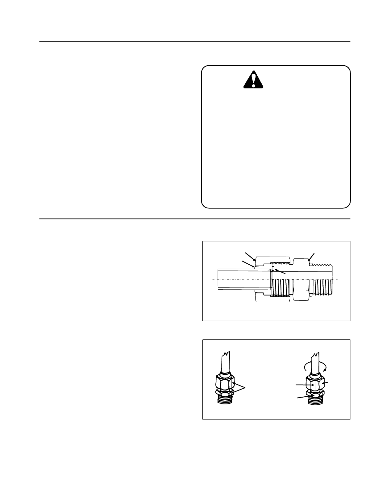
Hydraulic Fitting Installation
O-Ring Face Seal (Fig. 2, 3)
1. Make sure both threads an d sealing surfaces are free
of burrs, nicks, scratches, or any foreign material.
2. Make sure the O-ring is installed and properly seated
in the groove. It is recommended that the O-ring be
replaced any time the connection is opened.
3. Lubricate the O-ring with a light coating of oil.
4. Put the tube and nut square ly into position on the fac e
seal end of the fitting and tighten the nut until finger tight.
5. Mark the nut and fitting body. Hold the body with a
wrench. Use another wrenc h to tighten the nut to the
correct flats from finger tight (F .F.F.T.). The markings on
the nut and fitting body will verify that the connection has
been tightened.
Size F.F.F.T.
4 (1/4 in. nominal hose or tubing) .75 ± .25
6 (3/8 in.) .75 ± .25
8 (1/2 in.) .75 ± .25
10 (5/8 in.) 1.00 ± .25
12 (3/4 in.) .75 ± .25
16 (1 in.) .75 ± .25
Body
Sleeve
Seal
Figure 2
rk Nut
d Body
Finger Tight After Proper Tightening
Final
Position
Extend Line
Initial
Position
Figure 3
HydroJect™ 3000 Page 4 - 3 General Information
Page 22
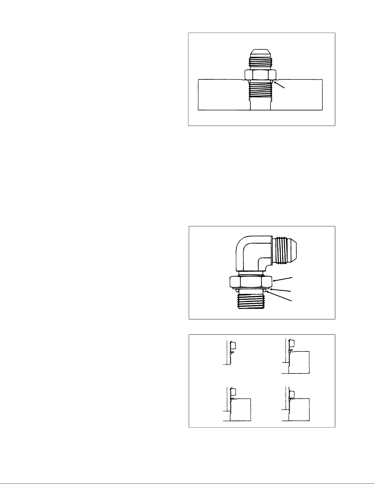
SAE Straight Thread O-Ring Port - Non-adjustable
(Fig. 4)
1. Make sure both threads and sealing surfaces are free
of burrs, nicks, scratches, or any foreign material.
2. Always replace the O-ring seal when this type of fitting
shows signs of leakage.
3. Lubricate the O-ring with a light coating of oil.
4. Install the fitting into th e port and tig hten it down full
length until finger tight.
5. Tighten the fitting to the correct flats from finger tight
(F.F.F.T.).
Size F.F.F.T.
4 (1/4 in. nominal hose or tubing) 1.00 ± .25
6 (3/8 in.) 1.50 ± .25
8 (1/2 in.) 1.50 ± .25
10 (5/8 in.) 1.50 ± .25
12 (3/4 in.) 1.50 ± .25
16 (1 in.) 1.50 ± .25
SAE Straight Thread O-Ring Port - Adjustable
(Fig. 5, 6)
1. Make sure both threads and sealing surfaces are free
of burrs, nicks, scratches, or any foreign material.
2. Always replace the O-ring seal when this type of fitting
shows signs of leakage.
3. Lubricate the O-ring with a light coating of oil.
4. Turn back the jam nut as far as possible. Make sure
the back up washer is not loose and is pushed up as fa r
as possible (Step 1).
O-Ring
Figure 4
Lock Nut
Back-Up Washer
O-Ring
5. Install the fitting into the port and tighten finger tight
Figure 5
until the washer contacts the face of th e po rt (Ste p 2).
6. T o put the fitting in the desired position, unscrew it by
the required amount, but no more than one full turn
Step 1
Step 3
(Step 3).
7. Hold the fitting in the desired position with a wrench
and turn the jam nut wit h an ot he r wr e nch to the correct
flats from finger tight (F.F .F.T.) (Step 4)
Size F.F.F.T.
4 (1/4 in. nominal hose or tubing) 1.00 ± .25
6 (3/8 in.) 1.50 ± .25
8 (1/2 in.) 1.50 ± .25
10 (5/8 in.) 1.50 ± .25
12 (3/4 in.) 1.50 ± .25
16 (1 in.) 1.50 ± .25
Step 2
Step 4
Figure 6
General Information Page 4 - 4 HydroJect™ 3000
Page 23

Pushing or Towing (Fig. 7)
The machine can be pushed or towed for very short
distances with the engine off, if necessary.
IMPORT ANT: Do not push or tow the machine faster
than 5 MPH because the hydraulic pump may be
damaged. If the machine must be moved further
than a few feet, transport it on a trailer or pull with
traction wheel raised and secured to a dolly. Whenever the machine is pushed or towed, the by-pass
valve must be open. Hook on front of handle is used
for a tie-down only , not a hitch point.
1. Stop the engine and raise the hood.
1
2. Open the by-pass valve by turning it counterclockwi se
(2 turns maximum).
3. After moving the machine, close the by-pass valve by
turning it clockwise. Tighten the by-pass valve to a
torque of 7 to 10 ft-lb.
IMPORTANT: Operating the machine with the bypass valve open will cause improper operation and
overheating of the hydraulic system.
Figure 7
1. By-pass valve
HydroJect™ 3000 Page 4 - 5 General Information
Page 24
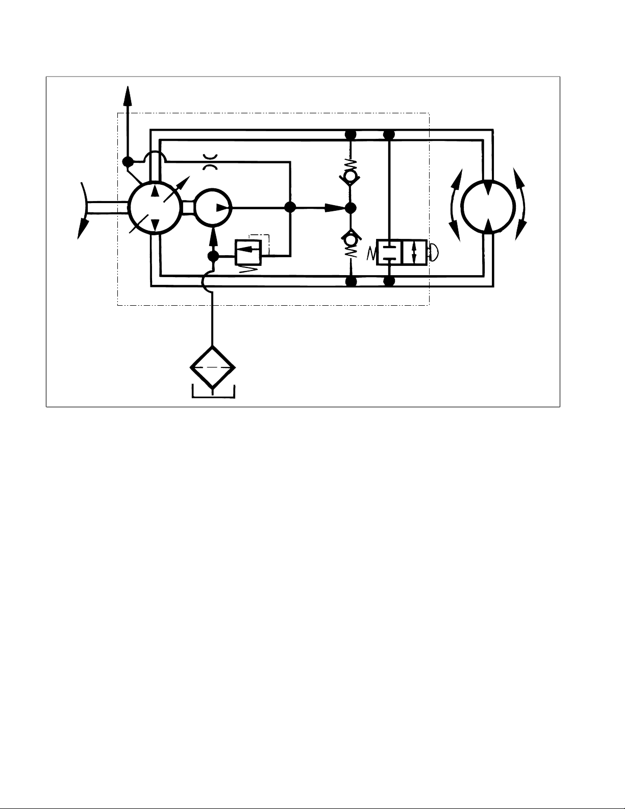
Hydraulic Diagram
Val
By-pass
ve
Variable Displacement Pump
Cooling
Orifice
Input
(Belt Drive)
Variable
sp. Pump
Di
Charge
Pump
Charge Relief
ve
Val
Inlet
Filter
Reservo
(Gear Case)
ir
Figure 8
Charge
Check
Valves
Wheel
Motor
Hydraulic Diagram Page 4 - 6 HydroJect™ 3000
Page 25
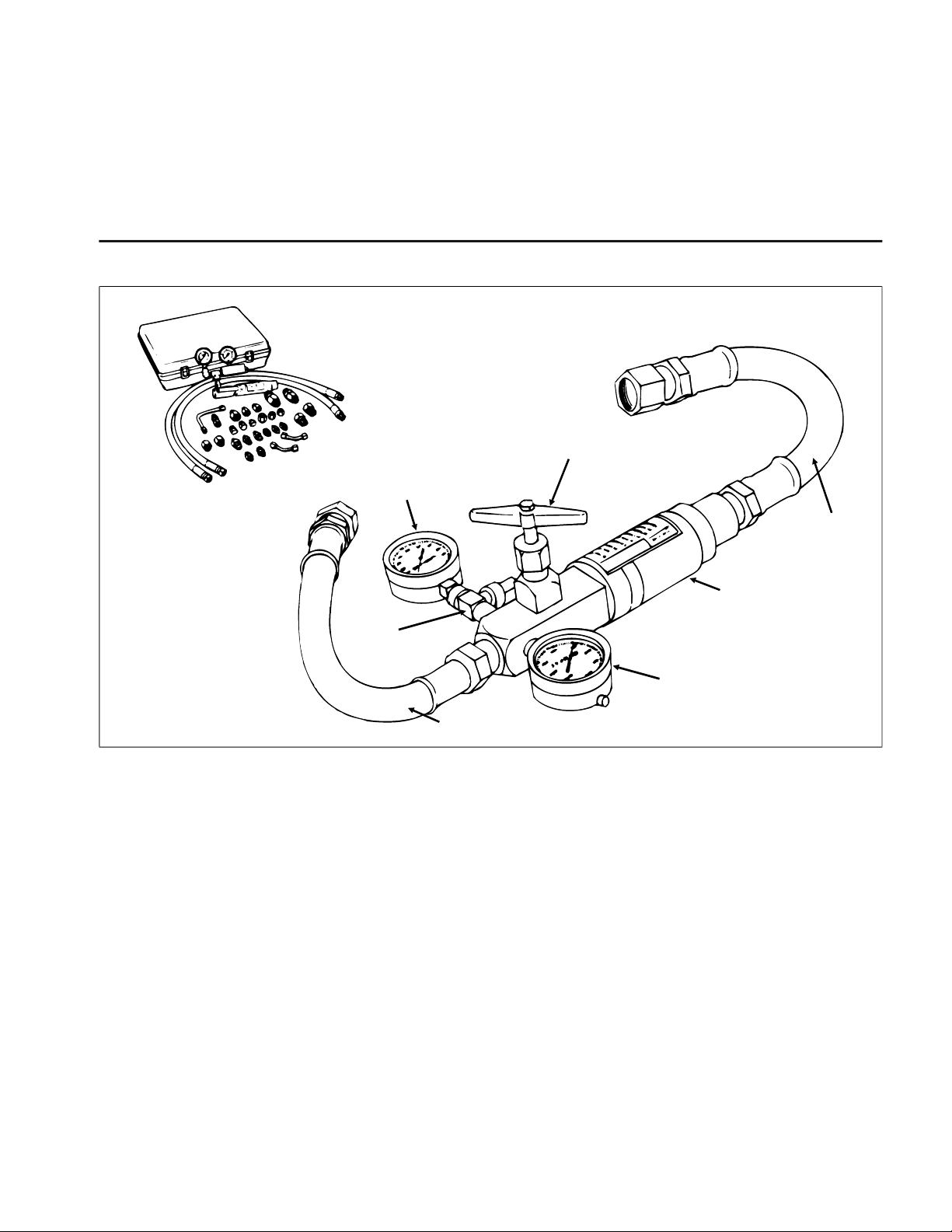
Special Tools
Gauge
High Pressure
NOTE: Order special tools from the
TORO SPECIAL
TOOLS AND APPLICATIONS GUIDE (COMMERCIAL
PRODUCTS)
. Some tools may be listed in the
HydroJect 3000 Parts Catalog. Some tools may also be
available from a local supplier.
Hydraulic Tester - With Pressure and Flow Capabilities (Fig. 9)
Load Valve
Low Pressure
Gauge
Outlet
Hose
Gauge
Protector Valve
Inlet Hose
Figure 9
You must have o-ring face seal (ORFS) adapter fittings
for this tester to use it on the HydroJect 3000.
1. INLET HOSE: Hose connected from the system
circuit to the inlet side of the hydraulic tester.
2. LOAD VALV E: If required, upon turning the valve to
restrict flow, a simulated working load is created in the
circuit.
3. LOW PRESSURE GAUGE: Low range gauge to
provide accurate reading at low pressure , 0 - 10 00 psi .
This gauge has a protector valve which cuts out
when pressure is about to exceed the normal range
for the gauge. The cutout pressure is adjustable.
Flow Meter
4. HIGH PRESSURE GAUGE: High range gauge to
accommodate pressure beyond the capacity of the low
pressure gauge, 0 - 5000.
5. FLOW METER: This meter measures actual oil flow
in the operation circuit, wi th a ga u ge r a te d at 15 G PM.
6. OUTLET HOSE: Hose from the outlet side of the
hydraulic tester to be connected to the hydraulic system
circuit.
HydroJect™ 3000 Page 4 - 7 Special Tools
Page 26

Troubleshooting
The cause of an improperly functioning hyd raulic system is best diagnosed with the use of proper testing
system could lead to extensive internal component
damage.
equipment and a thorough unde rstanding of the complete hydraulic system.
The charts that follow contain detailed information to
assist in troubleshoot ing. There may pos sibly be more
A hydraulic system with an excessive increase in heat
or noise is a potential failure. Should either of these
conditions be noticed, immediately stop the machine,
than one cause for a machine malfunction. All causes
should be checked in the order in which they are listed
on the charts.
turn off the engine, locate the cause of the trouble, and
correct it before allowing the machine to be us ed again.
Continued use of an improperly functioning hydraulic
Refer to the Testing section of this Chapter for precau-
tions and specific test procedures.
T ransmission Operates in One Direction Only
Cause Correction
__________________________________________________________________________________________
Faulty traction control linkage. Repair linkage
________________________________________________________________________________________________________________________________________________________
Transmission char ge che ck va lv e de fe cti ve . Inspect and clean or replace charge/check.
System Operates Hot, Looses Power or Will Not Operate in Either Direction
Cause Correction
__________________________________________________________________________________________
Faulty control linkage. Repair linkage
________________________________________________________________________________________________________________________________________________________
Parking brake engaged. Disengage parking brake.
________________________________________________________________________________________________________________________________________________________
Hydraulic oil level too low. Fill to proper level.
________________________________________________________________________________________________________________________________________________________
By-pass valve open. Close by-pass valve.
________________________________________________________________________________________________________________________________________________________
Clogged hydraulic filter. Replace filter.
________________________________________________________________________________________________________________________________________________________
Low charge pressure - Test A. Inspect charge relief valve and replace if faulty.
________________________________________________________________________________________________________________________________________________________
Low traction pump flow/pressure - Test B. Repair or replace pump.
________________________________________________________________________________________________________________________________________________________
Inspect charge pump and rep lace if faulty.
Low traction motor efficiency - Test C. Repair or replace traction motor.
Troubleshooting Page 4 - 8 HydroJect™ 3000
Page 27
Testing
The most effective method for i solati ng pro blems in the
hydraulic system is by using hydraulic te st equipment
such as pressure gauges an d flow meters i n the circuits
during various operational checks. (See the Special
Tools section in this Chapter.)
CAUTION
Failure to use gauges with the recommended
pressure (psi) rating as listed in the test procedures could result in damage to the gauge
and possible personal injury from leaking hot
oil.
Before Performing Hydraulic Tests
All obvious areas such as oil supply, filter, binding linkage, loose fasteners, or improper adjustments must be
checked before assuming th at a hydraulic component
is the source of the problem being experienced.
WARNING
Before disconnecting or performing any work
on the hydraulic system, all pressure in the
system must be relieved by stopping the engine and opening the bypass valve.
Keep body and hands away from pin hole
leaks or nozzles that eject hydraulic fluid under high pressure. Use paper or cardboard,
not hands, to search for leaks. Hydraulic fluid
escaping under pressure can have sufficient
force to penetrate skin and do serious damage. If fluid is injected into the skin, it must be
surgically removed within a few hours by a
doctor familiar with this type of injury or gangrene may result.
1. Thoroughly clean the machine befor e disconne cting
or disassembling any hydraulic components. Always
keep in mind the need for cleanliness when working on
hydraulic equipment.
2. Put caps or plugs on any hydraulic line s lef t open o r
exposed during testing or removal of components.
3. The engine must be in good operating condition. Use
a tachometer when making a hydraulic test. Engine
speed can affect the accuracy of the tester readings.
4. To prevent damage to tester or components, the inlet
and the outlet hoses must be properly connecte d, and
not reversed (tester with pressure and flow capabilities).
5. To minimize the possibility of damaging components,
completely open the load valv e by turning it counterclockwise (tester with pressure and flow capabilities).
6. Install fittings finger tight, far enough t o insure that
they are not cross-threaded, before tightening with a
wrench.
7. Position the tester hoses so that rotating machine
parts will not make contact with them and result in hose
or tester damage.
8. Check the oil level in the reservoir.
9. Check the control lin kage for improper adjustment,
binding or broken parts.
10. All hydraulic tests should be made with the hydraulic
oil at normal operating temperature.
HydroJect™ 3000 Page 4 - 9 Testing
Page 28
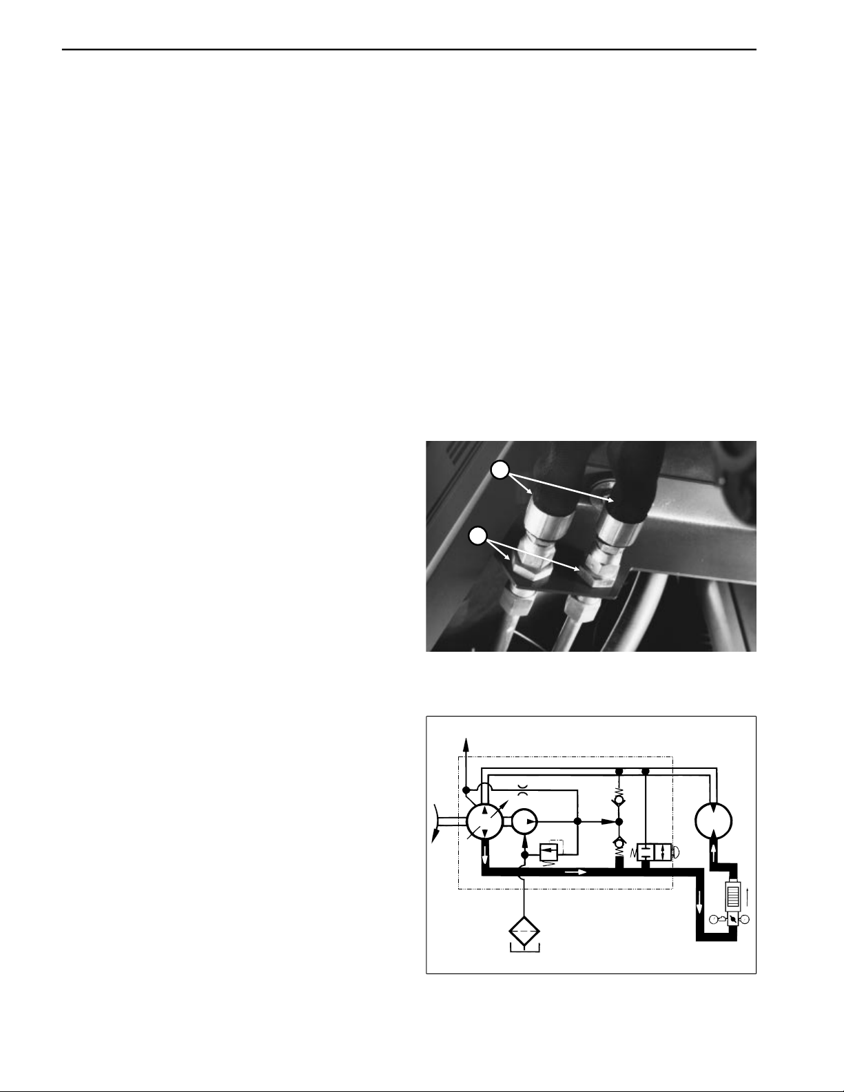
Hydraulic Tests (Fig. 10, 11)
1. Make sure hydraulic oil is at normal operating temperature by operating the machine for approximately 10
minutes.
2. Engage parking brake and stop the engine. Make
sure parking brake is properly adjusted before performing hydraulic tests.
3. With engine off, disconnect hose from bulkhead fitting
and install tester in ser ies between traction pump and
wheel motor. Make sure tester flow control valve is
OPEN.
IMPORTANT: Make sure that the oil flow indicator
arrow on the flow gauge is showing that oil will flow
from pump, through tester and to wheel motor.
Test A: Charge Pressure
4. Start the engine and move throttle to full engine RPM
(approx. 3200 RPM).
GAUGE READING: 25 to 70 PSI no load.
5. If there is no pressure, or pre ssure i s low, inspect for
restriction in pump intake line and inlet filter. Inspect
charge relief valve and valve seat. I nspect fo r sheared
charge pump key. Disassemble charge pump and inspect for internal damage or worn parts. If charge pump
is in good condition (no scoring, s cratches, or excessive
wear), piston pump and motor might be suspected of
wear and inefficiency, thus charge pump is unable to
keep up with internal leakage.
NOTE: At pressures above approximately 500 PSI,
mechanical override in handle will cause pump to begin
to de-stroke.
11. If you cannot get 7 GPM or 500 PSI , traction pump
may have internal damage or excessive wear.
TEST C: Traction Motor Efficiency
12. Lower drive wheel to ground and engage park ing
brake. Block front and rear of all wheels. Chain machine
to an immovable object and remove slack from chain.
13. With tester flow control valve open, slowly move
traction handle (up or dow n) so flow is f rom the pump,
through the tester, then to the wheel motor. Move trac-
tion handle until maximum pressure is attained with
wheel not rotating and read flow gauge.
14. If flow reading is higher than 1.5 GPM, motor may
have internal damage or excessive wear.
1
2
TEST B: Traction Pump Flow
6. Lift the drive wheel off the grou nd using a jack. Block
front and rear of the other whe els. Make sure the tes ter
flow control valve is OPEN.
7. Start the engine and release the parking brake.
8. While watching flow and pressure gauges, move
traction handle (up or dow n) so flow is f rom the pump,
through the tester, then to the wheel motor. Move traction handle until 6 GPM is obtained.
9. If pressure is less than 200 to 300 PSI g o to ste p 10.
If pressure is more than 200 to 300 PSI stop the engine
and inspect for binding parking b rake. Inspect for restrictioninlines to and from motor . If there are no restricti ons,
motor should be suspected of having internal damage.
10. While watching flow and pressure gauges, move
traction handle (up or down) to full speed position so
flow is from the pump, through the tester, then to the
wheel motor. Slowly close flow control valve until you
get readings of 7 GPM and 500 PSI.
Figure 10
1. Hose 2. Bulkhead fitting
Variable Displacement Pump
Tester
Figure 11
Wheel
Motor
Testing Page 4 - 10 HydroJect™ 3000
Page 29
Adjustments
10
T raction Cable Adjustment (Fig. 12)
1. Park machine on a level surface, stop the engine and
open the hood. Remove lower cover from handle.
1
2. Adjust pump end of push-pull cable wit h pump leve r
in neutral starting position by adjusting jam nuts so
distance from seal to threads is 1.00 ± 0.05 in.
3. Adjust jam nuts at tiller end of push-pull cable so
2
traction handle is centered on control handle.
Figure 12
1. Jam nuts - pump end 2. Jam nuts - tiller end
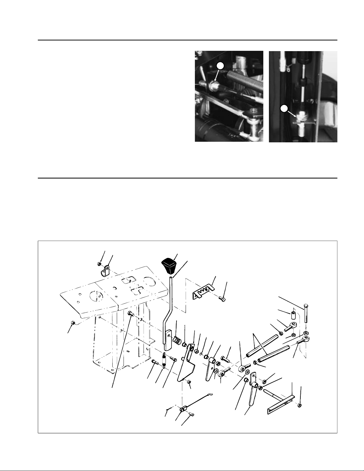
Speed Control Adjustment (Fig. 13)
1. Park machine on a level surface, stop the engine and 3. Adjust speed rods (Item 14) so rod end mounting
open the hood. holes in pivot arms (Items 11, 23) are located vertically
in line with pivot pin (Item 22).
2. Adjust speed control cable (I tem 26) so speed stop
lever (Item 9) can move to horizontal position.
24
1
2
28
30
29
27
28
26
3
7
25
4
5
6
17
16
8
9
24
8
8
11
12
19
20
19
14
13
8
23
15
15
13
19
21
18
20
8
22
18
HydroJect
Figure 13
™
3000 Page 4 - 11 Adjustments
Page 30
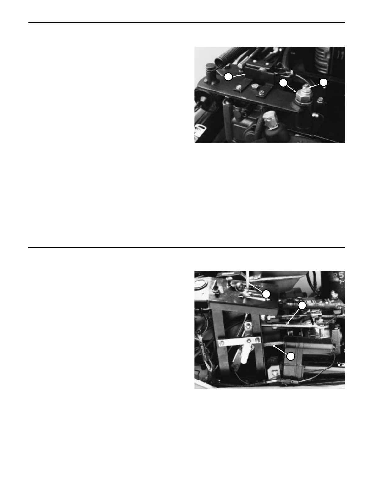
Tr ansmission Neutral Adjustment (Fig. 14)
1
If machine moves when l eve r i s released, transmissi o n
neutral adjustment is needed.
1. Park machine on a level surface, stop th e engine and
open the hood.
2. Lift drive wheel off the ground using a jack. Block front
and rear of other wheels.
3. Start engine and release parking brake.
4. Slightly loosen loc knut on top of neutr al adjustment
cam and rotate cam hex until traction wheel stops
rotating. Tighten the locknut.
5. Move traction bail completely up and down. Release
handle and check for wheel rotation. If wheel continues
rotating, repeat step 4.
6. If problem continues, stop the engine, check linkage
for binding or damage, then d o adjustment procedure
again.
7. Loosen two (2) screws and adjust switch tab so
switches are actuated when pump control is in neutral
and not actuated when pump control is stroked.
3
1
2
Figure 14
1. Neutral adjustment cam
2. Locknut
3. Switch tab
Aeration Speed Adjustment (Fig. 15)
1. Park machine on a level surface, stop th e engine and
open the hood.
2. Put speed control lever into second slot from left
(while facing control panel).
3. Lower machine into aerate mo de so transport wheel s
are off the ground.
4. Lift drive wheel off ground using a jack.
5. Start the engine and release the parking brake.
6. Operate engine at full speed.
7. Move traction handle UP to full speed position.
8. Loosen jam nuts and adjust LOWER speed rod until
traction wheel rotates at 20-22 RPM. Tighten jam nuts.
9. Move traction handle DOWN to full speed position.
10. Adjust UPPER speed rod until traction wheel rotates
at 20-22 RPM. Tighten jam nuts.
3
2
Figure 15
1. Speed control lever
2. Lower speed rod
3. Upper speed rod
Adjustments Page 4 - 12 HydroJect™ 3000
Page 31

T raction Pump Belt Adjustment (Fig. 16, 17)
2
1. Park machine on a level surface, stop the engine and
open the hood.
2. Check belt tension by depressing belt midway between pulleys with 3 lb. of force. Belt should deflect
1/4 in.
3. If adjustment is necessary:
A. Loosen pivot nut securing pump mount to pump
support.
B. Loosen adjusting nut securing pump and pump
mount to slotted pump support.
C. Loose three (3) capscr ews secu ring p ull ey gua rd
bracket (Fig. 20, Item 21) to contro l panel and pump
support.
D. Use a pry bar in hole on pump bracket to pull pump
towards outside of machine until you get proper belt
tension, then tighten adjusting nut to secure pump
and pump mount to pump support.
E. Tighten pivot nut. Tighten three (3) capscrews
securing pulley guard bracket.
1
Figure 16
1. Traction pump belt
1
Figure 17
1. Adjusting nut
2. Pivot nut
HydroJect™ 3000 Page 4 - 13
Rev . A
Adjustments
Page 32

Repairs
2
3
T r action Pump Belt Replacement (Fig. 18, 19)
1. Park machine on a level surface, engage parking
brake, open hood and disconnect engine spark plug
wires.
2. Remove pulley guard bracket (Fig. 20, Item 21).
3. Remove drive coupling (see Drive Coup ling Removal
and Installation in Chapter 6 - Water System).
4. Disconnect valve clutch electrical connector.
5. Remove valve clutch stops.
6. Loosen pivot nut securing pump mount to pump
support.
1
4
Figure 18
7. Loosen adjusting nut securing pump and pump mount
to slotted pump support.
8. Push pump towards inside of machine to loosen belt
tension and remove the belt.
9. Reverse steps 2 - 8 to install new belt.
10. Adjust belt tension (see Traction Pump Belt
Adjustment).
1. Pump drive belt
2. Drive coupling
3. Valve clutch
4. Valve clutch stops
1
2
Figure 19
1. Adjusting nut
2. Pivot nut
Repairs Page 4 - 14
Rev . A
HydroJect™ 3000
Page 33

Hydraulic Pump Removal and Installation (Fig. 20)
29
49
54
51
41
50
1. Park machine on a level surface, engage parking
brake, open hood and disconnect engine spark plug
wires.
2. Disconnect wires from neutral and pump switches
(Item 31) on hydraulic pump. Label wires for proper
reinstallation.
3. Remove extension spring (Item 17).
4. Disconnect stroke control cable ball joint (Item 43)
from pump lever (Item 30). Disconnec t upper and lower
speed adjustment rods from pump lever (see Fig. 14).
5. Loosen belt tension and remove belt from pump
pulley (see Pump Belt Tension Adjustment).
6. Disconnect hydraulic lines from fittings on pump. Put
caps on open lines and fittings to prevent contamination.
Put labels on hydraulic lines for proper reinstallation.
13
14
59
12
11
10
9
8
7
6
2
1
5
4
3
15
16
17
19
20
19
13
18
14
53
52
7. Remove locknut (Item 46), capscrew (Item 5) and
washers (Item 47). Remove locknut (Item 54) and capscrew (Item 57).
8. Remove pump assembly from pump support
(Item 55) and put pump on a work bench.
9. Loosen jam nuts (Item 3) and set screws (Item 2).
Remove pulley (Item 4) from pump shaft.
10. Remove pump mount (Item 6) from pump.
11. Loosen locknuts (Item 36) and remove roll pin
(Item 34). Pull pump lever (Item 30) off of pump control
shaft.
12. Remove hydraulic fittings from pump and plug ports.
13. Reverse steps 2 - 12 to install pump.
39
38
35
36
37
47
40
41
42
43
44
45
46
22
23
24
25
26
27
28
30
33
32
31
34
48
47
55
47
57
56
5
Figure 20
HydroJect™ 3000 Page 4 - 15 Repairs
Page 34

Pump Shaft Seal Replacement (Fig. 21)
Lip type seals are used on input shaft and displacement
controlshaft. These seals can be repl aced without major
disassembly of pump.
1. Remove retaining ring f rom ho usin g (inp ut sha ft seal
only).
2. Carefully pull seal out of housing bore. A “hook” type
tool may be used to grasp seal and pul l it out, o r a slide
hammer type puller may be used to remove seal. Be
careful not to damage housing bor e, shaft se aling surface, or bearing. After the sea l is remo ved, i t cann ot b e
used again.
IMPORTANT: When input shaft seal is removed,
pump block spring may push shaft partially out of
housing. Do not attempt to pull shaft out of housing.
Internal parts could move out of alignment or fall
into pump, requiring major disassembly of pump.
3. Inspect sealing area of shaft for rust, wear or contamination. Polish sealing ar ea on s ha ft if necessary.
4. Lubricate new seal with petroleum jelly.
Top of pump when
installed in machine
4
3
1
2
Figure 21
1. Retaining ring
2. Seal (input shaft)
3. Spacer
4. Seal (displacement control shaft)
5. Wrap shaft with thin plastic or use a seal protector to
prevent damage to seal lip during installation.
6. Slide seal over shaft and press it into housing bore.
Be careful not to damage the seal.
7. Install seal retaining ring into housing (input shaft seal
only).
Repairs Page 4 - 16 HydroJect™ 3000
Page 35

Pump Charge Check Valve Service (Fig. 22)
T
installe
T
ins
2
1. Remove check valve plug with a 1/4 in. internal hex
wrench.
2. Remove valve spring and check ball from pump end
cap.
IMPORTANT: Do not allow check balls to fall into
closed loop passages in end cap.
3. Inspect check balls and ma ting seats in en d cap for
damage or foreign mate ri al .
4. Lay pump on its side and reinstall check ball, sp ring
and plug (with O-ring) into end cap. Make sure check
ball does not fall into closed loop passage inside pump.
Tighten plug to a torque of 15 to 35 ft-lb. Turn pump over
and repeat installation procedure for other check valve.
op of pump when
d in machine
5
4
Figure 22
1. Check valve plug
2. O-ring
3. Check valve spring
4. Check ball
5. Pump end cap
Torque to
15 to 35 ft-lb.
3
2
1
Pump Bypass Valve Service (Fig. 23)
1. Unscrew bypass valve from end cap of pump.
2. Inspect valve and mating seat in end cap for damage
and foreign material. It is recommended that the O-ring
and back-up ring be replaced.
3. Reinstall bypass valve into end cap. Tighten to a
torque of 7 to 10 ft-lb.
Torque to
7 to 10 ft-lb.
1
3
op of pump when
talled in machine
4
Figure 23
1. Bypass valve
2. Back-up ring
3. O-ring
4. Pump end cap
HydroJect™ 3000 Page 4 - 17 Repairs
Page 36

Charge Pump Service (Fig. 24)
2
3
1. Use a 5 mm internal hex wrench to remove the two
(2) screws holding charg e pump cover to pump end cap.
NOTE: Charge pump rotation is determined by orientation of charge pump cover on pump end cap. Cast boss
on charge pump cover indi cates orientation. No te orientation of cast boss before remo ving charge pump cove r .
2. Remove charge pump cover and O-ring.
3. Remove charge pump gerotor assembly.
4. Remove charge relief valve spring and ball.
5. Inspect gerotor assembly, charge pump cover and
end cap for abnormal wea r , damage or fo reign material.
Inspect charge relief valve seat in end cap for damage
or foreign material.
6. Before installing charge pump, ap ply a sm all amount
of petroleum jelly to inside diamete r, outside diameter
and slide faces of gerotor assembly.
7. Install charge relief ball and spring.
Top of pump when
installed in machine
Torque to
84 to 120 in-lb.
1
5
4
Figure 24
1. Charge pump cover
2. O-ring
3. Gerotor assembly
4. Charge relief ball
5. Charge relief spring
8. Install charge pump gerotor assembly.
9. Install charge pump cover and O-ring. Make sure
charge relief spring enters recess in cover.
10. Install charge pump cover s crews and tighten to a
torque of 84 to 120 in-lb.
Major Pump Repair (Fig. 25, 26)
The procedures on the following pages are for complete
disassembly and reassembly of the pump.
Cleanliness is a primary means of assuring sati sfactory
transmission life, on either new or repair units. Cleaning
parts by using a clean solvent wash and air drying is
usually adequate. As with any precision equipment, all
parts must be kept free of foreign materials and chemicals. Protect all sealing surfaces and open cavities from
damage and foreign material.
During assembly of the p ump, all surf aces which hav e
relative motion between two parts should be coated with
a film of clean hydraulic oil. This will ass ure that these
surfaces will be lubricated during start-up.
It is recommended that all gaskets, o-rings and seals be
replaced. Lightly lubricate all o-rings with clean petroleum jelly before assembly. All gasket sealing surfaces
must be cleaned before installing new gaskets.
Repairs Page 4 - 18 HydroJect™ 3000
Page 37

19
20
21
22
23
24
40
39
35
34
17
26
18
25
16
12
8
1
2
3
4
38
37
36
33 31 32
7
6
5
30
3
4
11
10
9
1
2
13
29
15
14
27
28
Figure 25
Disassembly of Hydraulic Pump
1. Before performing major repairs on the pump, remove
external components as described in previous procedures. These include the following:
Shaft Seals
Charge Check Valves
Bypass Valve
Charge Pump
2. Lay pump on its side. Use a 6 mm internal hex wrench
to remove the four (4) screws (Item 30) which retain end
cap to variable pump housing.
3. Internal springs will separate end cap from h ousing.
Remove end cap (Item 31) from housing (Item 18).
IMPORT ANT: Pump cylinder block (Item 7) will stick
to surface of end cap. Be careful to prevent damage
to end cap and cylinder block.
4. Remove gasket (Item 6) and two (2) alignment pins
(Item 15) from housing.
5. Remove cylinder block kit (Item 7) from shaft
(Item 19).
6. Remove cylinder block spring (Item 8) and washer
(Item 9) from shaft.
7. Remove swashplate assembly (Item 25) from housing.
8. Remove thrust plate (Item 11) from swashplate. The
bearing guide is pressed into the swashplate and is
usually not removed. The inner thrust washer is retained
by the bearing guide.
9. Remove slot guide block (Item 13) from displacement
control shaft (Item 12).
10. Remove swashplate cradle bearings (Item 14) from
housing.
11. Remove input shaft seal retaining ring (Item 24).
12. Carefully pull input shaft seal (Item 23) out of housing bore. A h ook may be used to pry seal o ut, or a sl ide
hammer type puller may be used to remove the seal. Be
careful not to damage housing bore, shaft sealing surface, or bearing. After seal is removed it cannot be used
again.
13. Remove bearing spacer washer (Item 22).
HydroJect™ 3000
Page 4 - 19 Repairs
Page 38

14. Remove pump shaft (Item 19) and bearing assembly
from housing.
3. Install displaceme nt control shaft (I tem 12) into ho using.
15. Remove outer bearing retaining ring (Item 21) (and
washer, i f used). Press shaft out of beari ng.
16. If pump block retaining spring retaining ring
(Item 10) requires replacement, remove it from pump
shaft.
17. Remove displacement control shaft from housing.
18. Pry displacement c ontro l shaft s eal ou t of h ousing.
Care must be taken so as not t o dama ge housin g bo re.
19. If displacement co ntrol shaft journal bearing requires
replacement, press it out of housing.
Inspection and Replacement of Pump Parts
After disassembly, thoroughly clean all parts in a suitable solvent. Replace all o-rings, gaskets and seals.
Inspect all parts for damage, nicks or unusual wear
patterns. Replace all part s having unusua l or excessive
wear or discoloration.
Inspect seal surf aces, bearing s urfaces and s haft splines. Polish sealing areas on shafts if necessary. Replace any worn or damaged parts.
4. If block spring retaining ring (Item 10) was re moved
from pump shaft, install a new retaining ring at this time.
5. Install inner bearing retaining ring (Item 20) onto shaft.
Press bearing (Item 21) onto shaft, install washer (if
used) and new outer bearing re taining ring. Be careful
not to stretch or deform retaining rings.
IMPORT ANT : Be careful not to damage shaft sealing
surface.
6. Install pump shaft and bearing assembly into housing.
7. Install bearing spacer washer (Item 22).
8. Wrap shaft with thin pl asti c or u se a se al prote ctor to
prevent damage to seal during installation. Lubricate
new pump shaft seal (Item 23) with petroleum jelly.
9. Slide seal over shaft and press it into housing bore.
Be careful not to damage the seal.
10. Install retaining ring (Item 24).
11. Install swashplate cradle bearings (Item 14) into
housing, making sure they ar e located on cast-in pins in
housing.
The pump shaft bushing (Item 5) is pressed into end cap
and is usually not removed.
The running surfaces of cylinder blocks MUST be flat
and free from scratches. I f scratc hes or wear are fou nd
on running surfaces of cylinder blocks or end cap, polish
or replace the parts. When polishing these surfaces, up
to 0.0004 in. may be removed. If this is not sufficient to
obtain a flat surface, free of scratches, the part should
be replaced.
Assembly of Hydraulic Pump
1. Clean and lightly oil parts before assembly. Tig hten
all threaded parts to recommended torque value.
IMPORTANT: Most parts have critical, high tolerance surfaces. Use caution to prevent damage to
these surfaces during assembly. Protect exposed
surfaces, openings and ports from damage and
foreign material.
2. If displacement control shaf t bearing (Item 17) has
been removed, press a new bearing into housing using
a suitable press pin. Surface of bearing should be flush
with inside surface of housing.
12. Install slot guide block (Item 13) onto displacement
control shaft.
13. Install thrust plate (Item 11) into swashplate
(Item 25). Slot on swashplate must engage guide block
(Item 13) on displacement control shaft (Item 12). Use
a tool such as a screwdrive r or magnet to hold guide
block in position while installing swashplate.
14. Hold swashplate in position and use a dial indicator
or depth gauge to meas ure side play of displacement
control shaft. Using a suitable sle eve, press control shaft
bearing into housing until cont rol shaft end play is between 0.020 and 0.060 in.
15. Install thrust washer (Item 9) and cylinder block
spring (Item 8) onto pump shaft.
16. Install springs (Item 29), pis ton washers (Item 28)
and pistons (Item 27) into cylinder block kits. The pistons
must move freely in their bores.
17. With pump swashplate in “neutral” (0 angl e) position
and pump housing laying on its side, install pump cylinder block kit onto pump shaft in housing .
NOTE: The position of the bearing in the housing determines control shaft end play. Do not press bearing
deeper into housing at this time.
Repairs Page 4 - 20
HydroJect
™
3000
Page 39

18. Check that piston springs are c entered in cylinder
block bores, If necessary, move springs into position
with a small screwdriver.
21. When end cap is properly installed, the internal
springs will hold it away from the housing approximately
3/8 in.
IMPORTANT: Do not damage running surfaces of
cylinder blocks.
19. Install two (2) alignment pins (Item 15) and install a
new gasket (Item 6) onto housing.
20. Lubricate running surfaces of end cap (Item 31) and
cylinder blocks (Item 7). Position housing opening UP
and install end cap onto housing (Item 18).
IMPORTANT: Make sure all parts are properly
aligned. Do not force end cap into position on housing. Be careful to prevent damage to end cap and
cylinder block sealing surfaces.
12
13
22. Install the four (4) capscrews which retain end cap
to housing. Tighten screws to a torque of 138 to 180
in-lb.
23. Rotate shafts to assure correct assembly. When
properly assembled, minimal torque should be required
to turn shafts.
24. Wrap end of displacement control shaft with thin
plastic or use a seal protector to prevent damage to seal
during installation. Lubricate new displacement controls
shaft seal (Item 16) with p etrol eum jell y. Slide seal over
shaft and press it into housing bore. Be careful not to
damage seal. Install seal flush to bottomed in bore.
24
23
22
21
20
19
16
15
14
18
17
40
39
35
34
8
1
2
3
4
38
37
36
33 31 32
7
6
5
30
3
4
11
10
9
25
26
27
28
29
1
2
Figure 26
HydroJect™ 3000 Page 4 - 21 Repairs
Page 40

Wheel Motor Removal and Installation (Fig. 27)
2
3
1
4
37
36
35
34
33
32
31
9
5
30
8
6
7
29
28
27
17
26
10
11
12
13
25
14
15
16
17
18
19
20
Torque to
250 to 400 ft-lb.
21
22
23 24
Figure 27
1. Park machine on a level surface, engage parking
brake, open hood and disconnect engine spark plug
wires. Lift drive wheel off the ground using a jack. Block
front and rear of other wheels.
2. Remove wheel nuts (Item 23) and remove wheel.
Remove large nut (Item 22) from wheel hub.
3. Mount a wheel puller to wheel mount studs and
remove wheel hub (Item 19) and brake drum (Item 18).
Remove key (Item 7) from wheel mot or shaft.
IMPORTANT: To prevent damage to wheel motor,
DO NOT hit wheel hub with a hammer during removal or installation.
4. Disconnect hydraulic lines from fittings on wheel
motor. Put caps on open lines and fittings to p revent
contamination. Put labels on hydraulic lines for pro per
reinstallation.
5. Remove four (4) capscrews (Item 1), nuts (Item 27)
and lockwashers (Item 28) to remove wheel motor
(Item 6) and brake brackets (Item 29) from steering arm
(Item 37).
6. Reverse steps 1 - 6 to install wheel motor. When
installing wheel hub onto motor shaft, t ighten large nut
(Item 22) to 250 - 400 ft-lb.
Repairs Page 4 - 22
Rev . A
HydroJect™ 3000
Page 41

Wheel Motor Shaft Seal and/or Shaft Replacement (Fig. 28)
11
10
4
12
17
16
13
14
15
7
6
5
4
3
1
2
Figure 28
Disassembly of Shaft and Front Seal Assembly
1. Put motor on a clean, flat surface with shaft facing up.
Clean front end of motor to avoid contaminating internal
parts during procedure.
2. Remove key (Item 11) from shaft.
3. Remove snap ring (Item 14) using a snap ri ng pliers.
19
20
19
21
9
scratches, entire motor should be disassembled for
inspection.
Assembly of Shaft and Front Seal Assembly
1. Assemble thrust washers (Item 19) and thrust bearing
(Item 20) on shaft using the sn ap ring (Item 21). Sna p
ring sharp edges MUST face away from thrust washers
with thrust bearing (Item 20) between washers.
4. Pull shaft (Item 10) out vertically.
2. Slowly lower spline end of shaft (Item 10) assembly
into motor body using caution not to rotate internal parts
IMPORTANT: When pulling shaft vertically, do not
once shaft spline starts to engage.
rotate shaft or move motor as this may alter internal
timing.
3. Put lightly oiled o-ring (Item 12) into groov e in body
bore.
5. With seal retainer assembly and shaft assembly
removed, remove all parts from sh aft and inspect v arious parts of seal assembly (Item 15, 16, 17), shaft
(Item 10) and thrust bearing assembly (Item 19, 20, 21).
Replace any worn or damaged parts. Always replace
4. Gently slide oiled seal retainer assembly (Item 15, 16,
17) over shaft, chamfered side first, and press into body
bore. When fully in place, body snap ring groove will be
visible.
seal retainer assembly (Item 15, 16, 17). The shaft
should have smooth polis hed surfaces in bearing and
seal areas. If the shaft is lightly scratched in these areas,
polish with fine emery paper in a circum ferential direction. However, if the shaft has any pitting or deep
5. Install snap ring (Item 14 ) into its body groove with
snap ring’s sharp edges facing outward and retainer pin
between snap ring lugs. Be sure snap ring is completely
seated in groove.
HydroJect™ 3000 Page 4 - 23 Repairs
Page 42

Wheel Motor Repair (Fig. 29)
12
11
10
13
14
15
4
16
17
7
6
5
4
3
1
2
Figure 29
IMPORTANT: Before DISASSEMBLING motor, plug
open ports and clean all dirt from outside of motor.
IMPORT ANT: Before ASSEMBLING motor, lightly oil
all seals, rollers and threaded bolt ends.
19
20
19
21
9
NOTE: The check balls may fall into body tapered holes
or into body valve p orts during disassembly . Be sure tha t
the check balls are removed.
Disassembly of Shaft Section of Motor
Disassembly of Cover Section of Motor
(See Disassembly of Shaft and Front Seal Assembly
under Main Shaft Seal and/or Shaft Replacement.)
1. Remove key (Item 11) from shaft.
Assembly of Complete Motor
2. Mount motor in a vice or other holding device with
shaft facing down.
1. Before assembly, all parts must be cleaned with a
suitable solvent and free of nicks and burrs.
3. Remove the eight capscrews (Item 1).
2. Mount body with pilot and bearing facing up in a vise
4. Remove cover & bearing assembly (Item 2) and
or other holding mechanism.
square ring seal (Item 4).
3. Insert shaft (Item 10) and install seals and thrust
5. Remove IGR assembly (Item 5) starting with outer
locating ring, rollers, outer rolls, inner rotor and valve
plate (Item 7). If any of these components are damaged,
bearings. (See Assembly of Shaft and Front Seal Assembly under Main Shaft Seal and/or Shaft Replacement.)
entire IGR assembly must be repla ced.
4. Mount body with pilot and bearing facing down in a
6. Remove the two check balls (Item 6).
vise or other holding fixture.
5. Put rotary valve (Item 7) on shaft spline with “T”
shaped slots on first.
Repairs Page 4 - 24 HydroJect™ 3000
Page 43

6. Next put IGR inner member on shaft spline with
semi-circular roll pockets between rotary valve ports.
NOTE: Be sure not to dislodge body square ring seal
while moving locating ring.
7. Put contour member of IGR over inner and insert
seven rolls into inner pockets (large diameter rolls).
8. Lightly oil square ring seal (Item 4) and put in bo dy
groove.
9. Put check balls (Item 6) over the two 1/8" inch
diameter holes in body. Be sure the check balls do not
fall into body tapped holes.
10. Put locating ring section (4.5 inch diameter) of IGR
(Item 5) onto body with che ck ball holes facing downward over balls. Align the eight bolt holes in locating ring
with eight holes in body. The holes align in only one
position.
1 1. Install the eight locating ring rollers into their pockets
and oil lightly.
12. Put other lightly oiled square ring seal (Item 4) into
groove in cover and put cover over s haft end and align
bolt holes.
13. Install the eight bolts with lightly oiled thread ends
into bolt holes and tighten diagonally to 30 ft-lb.
NOTE: The shaft may not turn fre ely afte r assemb ly. A
short running period may be required.
HydroJect
™
3000 Page 4 - 25 Repairs
Page 44

Repairs Page 4 - 26 HydroJect™ 3000
Page 45

Table of Contents
Chapter 5
Electrical System
WIRING SCHEMATICS AND DIAGRAMS . . . . . . . . 2
Logic Chart . . . . . . . . . . . . . . . . . . . . . . . . . . . . . 2
Controller lights . . . . . . . . . . . . . . . . . . . . . . . . . 2.1
Wiring Schematic
Wiring Diagram – Main . . . . . . . . . . . . . . . . . . . . 4
Wiring Diagram – Control Panel . . . . . . . . . . . . . 5
Wiring Diagram – Tiller . . . . . . . . . . . . . . . . . . . . 6
SPECIAL TOOLS . . . . . . . . . . . . . . . . . . . . . . . . . . . 7
TROUBLESHOOTING . . . . . . . . . . . . . . . . . . . . . . . 9
Starting Problems . . . . . . . . . . . . . . . . . . . . . . . . 9
General Run and Transport Problems. . . . . . . . . 11
Aerate Operation Problems. . . . . . . . . . . . . . . . 13
Safety Interlock System Problems . . . . . . . . . . 15
TESTING . . . . . . . . . . . . . . . . . . . . . . . . . . . . . . . . 17
Verify Safety Interlock System Operation . . . . . 17
Clutch Engagement /
Electronic Control System Test
Ignition Key Switch . . . . . . . . . . . . . . . . . . . . . . 19
Controller. . . . . . . . . . . . . . . . . . . . . . . . . . . . . . 20
Neutral Switch and Transport Switch . . . . . . . . 20
. . . . . . . . . . . . . . . . . . . . . . . . 3
. . . . . . . . . . . . . 18
Lift Limit and Pump Start Limit Switches . . . . . . 21
Aerator Start and Stop Switches . . . . . . . . . . . . 21
Lift Switch . . . . . . . . . . . . . . . . . . . . . . . . . . . . . 22
Linear Actuator . . . . . . . . . . . . . . . . . . . . . . . . . 22
Brake Switch . . . . . . . . . . . . . . . . . . . . . . . . . . . 23
Pressure Gauge/Switch. . . . . . . . . . . . . . . . . . . 23
Accumulator Charge Switch . . . . . . . . . . . . . . . 23
Relays . . . . . . . . . . . . . . . . . . . . . . . . . . . . . . . . 24
Battery . . . . . . . . . . . . . . . . . . . . . . . . . . . . . . . . 24
Pump Clutch . . . . . . . . . . . . . . . . . . . . . . . . . . . 25
Valve Clutch. . . . . . . . . . . . . . . . . . . . . . . . . . . . 25
REPAIRS . . . . . . . . . . . . . . . . . . . . . . . . . . . . . . . . 26
Battery Service . . . . . . . . . . . . . . . . . . . . . . . . . 26
Neutral Switch and Pump Switch
Replacement and Adjustment
Fuse and Circuit Breaker. . . . . . . . . . . . . . . . . . 28
Controller Replacement. . . . . . . . . . . . . . . . . . . 28
Linear Actuator Replacement . . . . . . . . . . . . . . 29
Diode . . . . . . . . . . . . . . . . . . . . . . . . . . . . . . . . . 29
. . . . . . . . . . . . 27
HydroJect 3000 Page 5 - 1
Rev. B
Table of Contents
Page 46

Wiring Schematics and Diagrams
Logic Chart
Each line on the Logic Chart shows the combination of
switch conditions that must be made for the listed action
to occur. Example - START, under ACTIONS: For the
engine to start the Key Switch must be moved to Start
(making terminals B + I + S) and the hydraulic pump
must be in Neutral (neutral switch CLOSED).
KEY
X
Switch Closed
O
Switch Open
⊗
Switch Closed Momentarily
Switch Conditon Not Re
levent
SWITCHES
Start - Key Switch B + I + S
Run - Key Switch B + I + A / X + Y
Neutral Switch (HJ3000 only)
Oil Pressure Switch
Water Pressure Switch
Pump Start Limit Switch
Lift Limit Switch
Transport Switch (HJ3000 only)
Aerator Start (Engage) Switch
Aerator Stop (Disengage) Switch
Lift Switch UP (HJ3000 only)
Lift Switch DOWN (HJ3000 only)
ACTIONS
1. Start X X
2. Run X X
3. Machine Lower (aerate posi tion) X X O X
4. Aerate
5. Machine Raise (transport position) X X O
(see Controller Timing below)
Machine Moving (out of neutral) X X X X
Machine Stationary (neutral) X X X X X X
⊗
X X
Controller Timing
Aerate START-UP Sequence
1. Pump clutch engages immediately.
2. Valve clutch engages 5 seconds after pump clutch engages.
Aerate SHUT-DOWN Sequence (Neutral Delay)
1. Pump clutch disengages and green light goes off 4 seconds after transport switch opens (red light goes off).
2. After another 3 seconds, valve clutch will disengage.
NOTE: Keeping aerate start (engage) switch pushed in (closed) will keep green light on and override neutral delay
shut-down.
Brake Switch
Accumulator Charge Switch
Aerate SHUT-DOWN Sequence (Disengage Delay)
1. Pump clutch disengages and green light goes off immediately when stop (disengage) switch is pushed in (opens)
or if pump start limit switch or water pressure switch opens (yellow light goes off).
2. After another 3 seconds, valve clutch will disengage.
Wiring Schematics and Diagrams Page 5 - 2
Rev . B
HydroJect 3000
Page 47

Controller Lights
Lights (LED’s) on the controller indicate when the following inputs are made to the controller:
Red: Transport switch closed (traction bail in neu
tral).
Green: Aerate start (engage) switch closed. If red
and yellow lights are on, green light will stay on until
either red or yellow goes off.
Yellow: Pump start limit switch closed (machine
lowered to aerate position) and water pressure
switch closed (water pressure of more than 30 psi)
and accumulator charge pressure switch (nitrogen
pressure more than 1800 psi).
-
3
2
1
1. Red Light 2. Green Light 3. Yellow Light
Hydroject 3000
Page 5–2.1
Rev. B
Wiring Schematics and Diagrams
Page 48

Wiring Schematics and Diagrams
Page 5 – 2.2 Rev. B
Hydroject 3000
Page 49

Electrical Schematic
(Model 09800)
Figure 1
HydroJect 3000 Page 5 - 3 Wiring Schematics and Diagrams
Page 50

Wiring Diagram – Main
(Model 09800)
Figure 2
Wiring Schematics and Diagrams Page 5 - 4 HydroJect 3000
Page 51

Wiring Diagram – Control Panel
(Model 09800)
Figure 4
HydroJect 3000 Page 5 - 5 Wiring Schematics and Diagrams
Page 52

Wiring Diagram – Tiller
(Model 09800)
Figure 3
Wiring Schematics and Diagrams Page 5 - 6 HydroJect 3000
Page 53

Electrical Schematic (Model 09801)
Hydroject 3000
Page 5 – 6.1
Rev. B
Wiring Schematics and Diagrams
Page 54

Wiring Diagram – Main
(Model 09801)
TRANS
TRANS
CLOSED
CONTROL PANEL
CB ADC
B
A
OPEN
P < 1400
TRANSPORT
PRESSURE SWITCH
ACCUMULATOR CHARGE
CLOSED
P > 1800
AERATE
B
A
BLUE/RED
BLUE/RED
ORANGE
BLACK
GRAY
YELLOW
BROWN
RED
OPEN
TRANSPORT
PUMP START LIMIT
CLOSED
AERATE
VALVE
BLACK
B
CLUTCH
A
BLACK
RED
PUMP
CLUTCH
RED
A
BLUE
B
GRAY
A
B
YELLOW
RED/BLUE
GRAY
YELLOW
RED
LINEAR
ACTUATOR
YELLOW
B
B
GREEN
OPEN OPEN
AERATE
NEUTRAL SWITCH
COM
BLACK
NEUTRAL
RED/BLUE
M
RED
A
A
BLUE
CLOSED
OPEN
CLOSED
YELLOW
AERATE
TRANSPORT SWITCH
NEUTRAL
COM
OPEN CLOSED
OPEN
CLOSED
GRAY
PURPLE
START
PUMP CLUTCH
RELAY RELAY
BLACK
BLACK
ED
YELLOW
GRAY
C
BLACK
B
BROWN
A
ED
C
B
A
PURPLE
PINK
PURPLE
YELLOW
RED/BLUE
Wiring Schematics and Diagrams
YELLOW
BLACK
RED
RED
RED
GREEN
BROWN
PURPLE
BLUE
D
C
B
A
Page 5 – 6.2
PINK
D
TILLER
BLACK
YELLOW
BLACK
ORANGE
C
B
Rev. B
BLACK
LIFT DOWN
BLACK
BLACK
RED
BLACK
PINK
GRAY
BROWN
A
RELAY
LIFT UP
VALVE CLUTCH
RELAY RELAY
Hydroject 3000
Page 55

Wiring Diagram – Control Panel (Model 09801)
HOUR
METER
BLACK
GREEN
ORANGE
YELLOW
I
B
S
X
A
Y
KEY
SWITCH
B
C
A
ORANGE
BLUE/RED
BLACK
D
B
A
C
RED
GRAY
20 AMP
CURCUIT BREAKER
B
A
BA
PRESSURE
GAGE/SWITCH
KEY SWITCH
OFF NONE
RUN B+I+A X+Y
START B+I+S
ENGINE
VOLTAGE RECTIFIER
AC
B+
ALTERNATOR
AC
FUSE
30 AMP
PURPLE
DIODE
BLUE
BROWN
IGNITION
RED
N.O.
OIL PRESSURE
– +
S
B
BATTERY
M
STARTER
Hydroject 3000
Page 5 – 6.3
Rev. B
Wiring Schematics and Diagrams
Page 56

Wiring Diagram – Tiller (Model 09801)
ALARM
–
+
NORMALLY
CLOSED
E
BLUE
D
PURPLE
BROWN
BAC
GREEN
PINK
BLACK
ORANGE
ED C B A
YELLOW
YELLOW
GREEN
N.O.
BRAKE
SWITCH
N.C.
AERATOR
STOP
COMMON
OPEN
NORMALLY
N.O.
AERATOR
START
SWITCH
COMMON
Wiring Schematics and Diagrams
ORANGE
PINK
Page 5 – 6.4 Rev. B
ORANGE
ORANGE
DOWN
BROWN
UP
Hydroject 3000
LIFT
SWITCH
Page 57

Special Tools
NOTE: Order special tools from the
TOOLS AND APPLICATIONS GUIDE (COMMERCIAL
PRODUCTS)
supplier.
. Some tools may be available from a local
TORO SPECIAL
Digital Multimeter (Fig. 6)
The meter can test electrical components and circuits
for current, resistance, or voltage drop.
NOTE: Toro recommends the use of a DIGITAL meter
when testing electrical circuits. The high impedance
(internal resistance) of a digital meter will ensure that
excess current is not allowed through the meter. Excess
current can cuase damage to a circuit that is not designed to carry it.
Figure 6
HydroJect 3000 Page 5 - 7
Rev. B
Special Tools
Page 58

Skin-Over Grease (Fig. 7)
Special non-conductive grease which forms a light protective skin to help waterproof electrical switches and
contacts.
Toro P/N
505-47
8 oz. (.24 L) can
Figure 7
Special Tools Page 5 - 8
Rev. B
HydroJect 3000
Page 59

Troubleshooting
CAUTION
Remove all jewelry, especially rings and
watches, before doing any electrical troubleshooting or testing. Disconnect the battery cables unless the test requires battery
voltage.
Study the operating characteristics preceding the electrical failure to help ide ntify the ar ea of difficulty. Try to
isolate the failure to a specific functional system; then
check that area, repairing one component at a time.
Attempting to repair more than one system at one time
will lead to confusion.
Possible Causes and Corrections in the troublesho oting
charts should be checked in t he order i n which they are
listed.
For effective troubleshooting and repairs, you MUST
have a good understanding of the electrical circuits and
components used on this machine. (See Electrical
Schematic.)
If the machine being repaired has any interlock switches
by-passed, they must be reconnected for proper troubleshooting and safety.
Starting Problems
Condition Possible Cause Correction
___________________________________________________________________________________________
Engine fails to crank, regardless Loose or corroded battery connecof traction bail position. tions.
Low battery charge.
Circuit breaker open.
Clean and tighten connections.
Charge battery. Replace battery if
it will not hold a charge (also see
Battery does not charge under
General Run and Transport Problems).
Reset circuit breaker. Find cause
for open circuit breaker and correct. Replace circuit breaker if
faulty.
Ignition key switch faulty.
Neutral switch faulty.
Start relay faulty.
Starter solenoid faulty.
Starter is faulty.
Engine is seized.
Loose or damaged wiring.
HydroJect™ 3000 Page 5 - 9 Troubleshooting
Test switch and replace if faulty.
Make sure switch is properly in-
stalled and adjuste d. Test switch
and replace if faulty.
Test relay and replace if faulty.
Test starter solenoid and replace
if faulty.
Test starter and repair replace if
faulty.
Repair engine.
Check connections. Repair wiring.
Page 60

Starting Problems (continued)
Condition Possible Cause Correction
__________________________________________________________________________________________
Engine cranks, but does not start.
Engine or rectifier plug loose.
Connect wire.
NOTE: If engine cranks, cause of
problem is UNRELATED to inter- “I” terminal on ignition key switch
Connect wire.
lock system. loose.
Diode in wire harness faulty.
Engine problem, or no fuel.
________________________________________________________________________________________________________________________________________________________
Replace diode
Find problem and correct (see
Chapter 3 - Engine).
Engine cranks (but should not) See Safety Interlock System Probwith traction bail in neutral.
________________________________________________________________________________________________________________________________________________________
Engine starts, but shuts down
when ignition key switch is re-
lems.
Not electrical - regulate choke dur- Normal condition.
ing cold start-up.
leased to RUN position.
Not electrical - low engine oil pres- Find and correct cause of low ensure.
gine oil pressure.
Oil pressure switch faulty. Test switch and replace if faulty.
Loose or broken wire in oil pres- Check all wiring and connections
________________________________________________________________________________________________________________________________________________________
sure switch circuit.
and repair as necessary.
Starter does not disengage whe n
key switch is released to RUN position.
Ignition switch faulty. Test ignition key switch and re-
place if faulty.
Short in start circuit wiring.
Check all wiring and connections
and repair as necessary.
Diode in wire harness faulty. Replace diode.
Start relay faulty. Test start relay and replace if nec-
essary.
Starter solenoid faulty. Test starter solenoid and replace
if necessary.
Starter failed (mechanical). Test starter and replace if neces-
sary .
Troubleshooting Page 5 - 10 HydroJect™ 3000
Page 61

General Run and Transport Problems
Condition Possible Cause Correction
___________________________________________________________________________________________
Engine shuts down during transport or when idling (not in Aerate
Not electrical - low engine oil pres- Find and correct cause of engine
sure, no fuel, etc. shut down.
mode).
Oil pressure switch faulty.
Test switch and replace if faulty.
Loose or broken wire in oil pres- Check all wiring and connections
________________________________________________________________________________________________________________________________________________________
Engine does not stop when ignition key switch is rotated to OFF
sure switch circuit.
Engine timing or carburetor out of Adjust carburetor or engine timadjustment. ing.
and repair as necessary.
position.
Ignition switch faulty.
Test ignition switch and replace if
faulty.
Short in ignition circuit wiring. Check all wiring and connections
________________________________________________________________________________________________________________________________________________________
and repair as necessary.
Battery does not charge. Open or missing 30 AMP fuse. Install new fuse. Find and correct
cause of open fuse.
Loose wire(s) in electrical system. Check for loose wire at “X” or “Y”
terminal of ignition switch. Check
all other connections and wires
on engine regulator.
Regulator or engine charging circuit faulty.
Battery faulty.
________________________________________________________________________________________________________________________________________________________
Ignition switch faulty.
Install new regulator or repair engine charging circuit.
Test battery and replace if faulty.
Test switch and replace if faulty.
Machine does not lower (to aer- Circuit breaker open. Reset circuit breaker. Find cause
ate position).
for open circuit breaker and correct. Replace circuit breaker if
faulty.
Lift/lower switch faulty.
Lift DOWN relay faulty.
Ignition key switch faulty.
Test switch and replace if faulty.
Test relay and replace if faulty.
Test ignition switch and replace if
faulty.
Loose or broken wire in lift down
circuit.
Linear actuator faulty.
Check all wiring and connections
and repair as necessary.
Test actuator and repair or replace if faulty.
HydroJect™ 3000 Page 5 - 11 Troubleshooting
Page 62

General Run and Transport Problems (continued)
Condition Possible Cause Correction
__________________________________________________________________________________________
Machine does not raise (to trans- Circuit breaker open. Reset circuit breaker. Fi n d cau se
port position). for open circuit breaker and cor-
rect. Replace circuit breaker if
faulty.
Lift/Lower switch faulty.
Lift UP relay faulty.
Ignition key switch faulty.
Test switch and replace if faulty.
Test relay and replace if faulty.
Test ignition switch and replace if
faulty.
Loose or broken wire in lift up circuit.
Linear actuator faulty.
________________________________________________________________________________________________________________________________________________________
Linear actuator continues to oper-
Lift limit switch faulty. Make sure switch is installed
ate (but should not) after machine
is lowered to aerate position.
Check all wiring and connections
and repair as necessary.
Test actuator and repair or replace if faulty.
properly. Test switch and replace
if faulty.
Troubleshooting Page 5 - 12 HydroJect™ 3000
Page 63

Aerate Operation Problems
Condition Possible Cause Correction
___________________________________________________________________________________________
Machine continues to aerate (but
should not) with traction bail in
neutral.
________________________________________________________________________________________________________________________________________________________
Machine aerates (but should not)
with with machine raised in transport position.
________________________________________________________________________________________________________________________________________________________
Machine starts aerating (but
See Safety Interlock System Problems.
See Safety Interlock System Problems.
Water pressure switch faulty. Test switch and replace if faulty.
should not) with inlet water pressure of less than 20 to 30 PSI, or
machine does not stop aerating if
inlet water pressure drops to
Water pressure switch wiring faulty. Check for short in pressure
switch/controller connections and
wiring and repair as necessary.
10 PSI.
________________________________________________________________________________________________________________________________________________________
Machine does not start aerating
when engage button is pushed in
Controller faulty.
Problem not electrical (see Chap-
ter 6 - Water System.)
Replace controller.
(pump drive belt does NOT rotate).
Circuit breaker open.
Reset circuit breaker. Find cause
for open circuit breaker. Replace
circuit breaker if faulty.
Loose or broken wire.
Check all connections and wiring
and repair as necessary.
Accumulator charge switch faulty
(Model 09801).
Pressure gauge switch faulty.
Pump clutch faulty.
Pump relay faulty.
Aerator stop (disengage) switch
faulty.
Pump start limit switch faulty.
Aerator start (engage) switch faulty.
Controller faulty.
Test switch and replace if faulty.
Test switch and replace if faulty.
Test clutch and replace if faulty.
Test relay and replace if faulty.
Test switch and replace if faulty.
Make sure switch is installed
properly. Test switch and replace
if faulty.
Test switch and replace if faulty.
Replace controller.
HydroJect 3000
Page 5 - 13
Rev. B
Troubleshooting
Page 64

Aerate Operation Problems (continued)
Condition Possible Cause Correction
__________________________________________________________________________________________
Machine does not start aerating
when engage button is pushed in
V alve clutch out of adjustment.
Check air gap on valve clutch
and adjust if necessary.
(pump belt IS rotating, but gearcase drive shaft is NOT rotating).
Loose or broken wire in valve
clutch / controller circuit.
Valve clutch faulty.
Check all connections and wiring
and repair as necessary.
Test valve clutch and repair or re-
place if faulty.
Valve clutch relay faulty.
________________________________________________________________________________________________________________________________________________________
Controller faulty.
Machine stops aerating when not It is normal for pump clutch and
moving (traction bail in neutral). water clutch to disengage when
traction bail is neutral for 3 to 4 sec-
________________________________________________________________________________________________________________________________________________________
Machine stops aerating while machine is moving (traction bail out
of neutral).
onds.
Problem not electrical (see Troubleshooting in Chapter 6 - Water
System.)
Transport switch faulty.
Test relay and replace if faulty.
Replace controller.
Educate operator. NOTE: Holding
Aerate start switch in ENGAGE
position will override neutral de-
lay shut-down.
Make sure switch is installed and
adjusted properly. Test switch
and replace if faulty.
Loose or broken wire in transport
switch / controller circuit.
Also see possible causes in (Water
pump clutch does not engage) and
(Water pump clutch engages, but
water valve clutch does not engage.)
Check all connections and wiring
and repair as necessary.
Troubleshooting Page 5 - 14
HydroJect 3000
Page 65

Safety Interlock System Problems
Condition Possible Cause Correction
___________________________________________________________________________________________
Engine cranks (but should not) Neutral switch faulty. Make sure switch is installed and
with traction bail in neutral. adjusted properly. Test neutral
switch and replace if faulty.
Neutral switch wiring faulty. Check for short in neutral switch
wiring and connections and repair
________________________________________________________________________________________________________________________________________________________
as necessary.
Machine continues to aerate (but
should not) with traction bail in
neutral.
Red light on controller is ON
(should be OFF) with traction bail
in neutral.
Make sure transport switch is installed and adjusted properly.
Test transport switch and replace
if faulty.
Check for short in transport
switch/controller connections and
wiring and repair as necessary.
Green light on controller stays ON
(should be OFF) with aerate engage switch released.
Test aerate engage (start) switch
and replace if faulty (make sure
switch action is momentary and
comes comes back out after being pushed in).
________________________________________________________________________________________________________________________________________________________
Machine aerates (but should not)
with with machine raised in transport position.
Controller faulty.
Yellow light on controller is ON T est pump start limit switch and
(should be OFF) with machine replace if faulty.
raised in transport position.
Replace controller.
Check for short in pump start limit
switch connections and wiring
and repair as necessary.
Controller faulty. Replace controller.
HydroJect™ 3000 Page 5 - 15 Troubleshooting
Page 66

Safety Interlock System Problems (continued)
Condition Possible Cause Correction
__________________________________________________________________________________________
No lights on controller come on
when troubleshooting i n te rl o ck
system.
Battery is dead or disconnected.
Circuit breaker open.
Charge battery. Replace battery if
it will not hold a charge. Clean
and tighten connections.
Reset circuit breaker. Find cause
for open circuit breaker and correct. Replace circuit breaker if
faulty.
Faulty controller ground.
Check controller ground connection and wiring and repair as necessary.
Ignition key switch faulty.
Test ignition switch and replace if
faulty.
Loose or damaged wiring in key
switch/controller circuit.
________________________________________________________________________________________________________________________________________________________
Green light on controller glows
Controller faulty.
Normal condition.
Check all connections and wiring
and repair as necessary.
Replace controller.
faintly when only red light should
be on (traction bail out of neutral
and aerate engage switch released).
Troubleshooting Page 5 - 16 HydroJect™ 3000
Page 67

Testing
It is often to the technician’s advantage to leave the
components intact in the electrical system, and by
studying the electrical tr oubleshoo ting charts and sch ematics, determine which component is at fault. However, thi s section will define given compo nents, and the
tests that can be perfor med on those components, when
those parts are disconnected from the el ectrical system.
For accurate resistance and/or continuity checks, electrically disconnect the component being tested from the
circuit.
Verify Safety Interlock System Operation
CAUTION
When testing electrical components for continuity with a volt-ohm meter or continuity
tester, make sure that power to the circuit has
been disconnected.
NOTE: Electrical troublesho oting of any 12 Volt power
connection can also be performed through voltage drop
tests without disconnection of the component.
The safety interlock system prevents the engine from
cranking or starting, unless tracti on bail is in NEUTRAL
and prevents the water system from engaging if machine is in the transport (ra ised) position. It also stops
aeration if traction bail is release d while operating or if
machine is raised to the transport position.
CAUTION
The interlock switches are for the operator’s
protection, DO NOT disconnect them.
Check operation of switches daily to make
sure interlock system is operating. If a switch
is defective, replace it before operating. Regardless if switches are operating properly or
not, replace interlock switches every two (2)
years to assure maximum safety. Do not rely
entirely on safety switches; use common
sense!
To do a functional check of interlock system:
1. Put machine in a flat, open area on rough turf away
from buried wires, plumbing, etc. Stop the engine.
2. Move traction bail up and down while trying to start
the engine. If engine cranks there is a malfunction in the
interlock system that must be correct ed. If en gine does
not crank, go to step 3.
so
3. Connect water supply to machine. Turn on water
supply and bleed all air out of the system. Water pressure must be 20 to 30 PSI or more. Start the engine.
Raise machine to transport position (up off of rollers).
Push aerate ENGAGE button. If water pump engages
and machine begins aerating, there is a malfunction in
the interlock system that must be corrected. If machine
does not begin aerating, go to step 4.
4. Lower machine to aerate position (on rollers). Engage
traction bail to start machine moving. Push, then release
aerate ENGAGE button. Water pump should engage
immediately , then mach ine should begin aeratin g 5 seconds after pump engages. Release traction bail to neutral position so machine sto ps moving. The wa ter pump
should disengage 4 seconds after traction bail returns
to neutral, then stop aerating a fter another 3 sec onds.
If machine does not stop aerating when traction bail
returns to neutral, there is a malfunction in the interlock
system that must be corrected. If machine stops aerating, go to step 5.
5. Engage traction bail to start machine moving, then
push aerate ENGAGE button to begin aerating. Push
aerate DISENGAGE button. The water pump should
disengage immediately, then stop aerating after 3 seconds. If machine does not stop aerating, there is a
malfunction in the interlock system that must be corrected.
HydroJect™ 3000 Page 5 - 17 Testing
Page 68

Clutch Engagement / Electronic Control System Test (Fig. 8)
3
This test can be used to check for proper operation of
the electronic contro l sys te m and clu tche s wi tho ut co n necting the machine to a water s our ce or op era ti n g th e
machine.
1. Park machine on a level surface, stop the engine,
engage the parking brake, open the hood and disconnect the engine spark plug wires.
2. Disconnect wiring harness connector from bottom of
water pressure gauge. Install a jumper wire across
terminals of disconnected wire connector. This will electrically by-pass the water pressure switch.
3. Turn ignition key switch to ON position. DO NOT start
the engine.
4. ENGAGE test:
A. Lower machine to aerate position (on rollers).
Yellow light should be ON.
B. Move traction bail out of neutral. Red light should
come ON.
B. After clutches are engaged, push red aerate
DISENGAGE button.
C. Green light should immediately turn OFF and
pump clutch should disenga g e.
D. After 3 seconds, valve clutch should disengage.
E. System must not restart wit hout pushing green
aerate ENGAGE button.
IMPORTANT: When test is completed, water pressure switch by-pass must be removed to prevent
damage to water system from low inlet water pressure.
7. Remove by-pass jumper wire that was connected in
step 2 and connect wire harness connector to terminals
on bottom of water pressure gauge.
C. With traction bail out of neut ral, push, then release, green aerate ENGAGE button. Green light
should come ON and pump clutch should engage.
After 5 seconds valve clutch should engage.
NOTE: Touch clutches with a metal object, such as
a screw driver, to help che ck for cl utch e ngage ment
(clutch will be magnetized).
5. NEUTRAL shut-down test:
A. Release traction bail. Red light should turn OFF.
B. After 4 seconds, pump clutch should disengage
and green light should go OFF.
C. After another 3 seconds, valve clutch should
disengage.
6. DISENGAGE test:
A. Move traction bail out of neutral and push green
aerate ENGAGE button.
1
2
Figure 8A
1. Red light
2. Green light
3. Yellow light
Testing Page 5 - 18
Rev . A
Figure 8B
1. Red light
2. Green light
3. Yellow light
HydroJect™ 3000
Page 69

Ignition Key Switch (Fig. 9, 10)
I
A
Y
CONT
AM
TE
NONE
The ignition (key) switch has three positions (OFF,
ST ART and RUN). The terminals are marke d as shown.
B
S
X
Figure 9
The circuitry of the ignition switch is shown in the chart.
With the use of a continuity tester, the switch functions
may be tested to determine whether all circuits are being
completed while the key is moved to each position.
POSITION
1. OFF
2. RUN
3. START
INUITY
ONG
RMINALS
B + I + A
B + I + S
Figure 10
OTHER
CIRCUITS
MADE
NONE
X + Y
NONE
HydroJect™ 3000 Page 5 - 19 Testing
Page 70

Controller (Fig. 11)
3
The controller senses the condition of various switches,
such as the transport switch a nd aerate start switch an d
directs power output to allow certa in machine function s,
such as aerate engage, disengage and ti ming o f thos e
functions.
Because of the solid state circuitry built into the controller, there is no method to test it directly. The controller
may be damaged if an attempt is made to test it wi th an
electrical test device, such as a volt-ohm meter.
IMPORTANT: Before welding on the machine, disconnect both battery cables from the battery, disconnect both wire harness plugs from the electronic
control unit and disconnect the terminal connector
from the alternator to prevent damage to the electrical system.
Lights (LED’s) on the controller indicate the condition of
the interlock switches. The LED’s, in conjunction with
the following tests fo r interlock switches, should be used
to help isolate a problem in an interlock switch, wiring or
the controller (see Wiring Schematics and Diagrams).
Neutral Switch and Tr ansport Switch (Fig. 12)
The neutral switch is normally open (N.O.) and is closed
when traction bail is neutral. The transport switch is
normally closed (N.C.) andis open when the traction ba il
is in neutral.
IMPORTANT: The neutral and transport switches
have three (3) terminals. The NEUTRAL SWITCH
must have the wires connected to the “COMMON”
and “N.O.” terminals. The TRANSPORT SWITCH
must have the wires connected to the “COMMON”
and “N.C.” terminals. If the wires are not connected
to the correct terminals, on each switch the safety
interlock circuit will not function properly .
1
2
Figure 11
1. Red light
2. Yellow light
3. Green light
3
1
2
Test the switch by disconnecting the wires from the
Figure 12
switch terminals and connecting a continuity tester
across the two terminals that had wires connected to
them. With the engine turned off, slowly push the traction bail in a forward and reverse direction while watch-
1. Neutral switch –– N.O. (black & red/blue wires)
2. Transport sw itch –– N.C. (yellow & gray wires)
3. Switch tab
ing the continuity tester. There should be indications that
the switch is opening and closing. Allow the traction bail
to return to neutral. There should be continuity across
the terminals of the neutral switch and no continuity
across the terminals of the transport switch. (See Neutral Switch and T rans port Switch Re place ment a nd Adjustment in the Repairs section of this chapter for
replacement and adjustment procedures.)
Testing Page 5 - 20 HydroJect™ 3000
Page 71

Lift Limit Switch and Pump Start Limit Switch (Fig. 13)
Test the switch by disconnecting the wire connector and
installing a continuity tester or ohm meter across the two
leads of the switch.
Lift Limit Switch
Aerate (machine lowered) Transport (machine raised)
OPEN CLOSED
Pump Start Limit Switch
Aerate (machine lowered) Transport (machine raised)
CLOSED OPEN
2
1
NOTE: For proper operation, the switch must be
screwed all the way in. A damaged pivot shaft or bushings could cause the switch to not open and close
properly. Debris in the switch could also cause it to not
open and close properly.
Aerator Start and Stop Switches (Fig. 14)
The aeration start (ENGAGE) switch is nor mally open
(N.O.) and closes when the button is pushed down. Th e
aeration stop (DISENGAGE) switch is normally closed
(N.C.) and opens when the button is pushed down.
Test the switch by disconnecting the wires from the
switch terminals and connecting a continuity tester or
ohm meter across the two switch terminals.
Figure 13
1. Pump start limit switch (blue/red & red/blue wires)
2. Lift limit switch (white & black wires)
1
2
1
2
Figure 14
1. Aeration start switch (pink & orange wires)
2. Aeration stop switch (blue & purple wires)
HydroJect™ 3000 Page 5 - 21 Testing
Page 72

Lift Switch (Fig. 15)
1
The lift switch is a three position switch. Switch position
is maintained in center position with no circuits made.
Test the switch by disconnecting the wires from the
switch terminals and connectin g a continuity tester or
ohm meter across terminal 2 (common) and terminal 1
or 3. With switch pushed toward keyway in threads,
terminals 1 and 2 are made. With switc h pushe d away
from keyway in threads, terminals 2 and 3 are made.
Linear Actuator (Fig. 16)
The linear actuator has a bi-dire ctional electric motor
which engages a clutch and screw mechanism to extend or retract a rod and raise or lower the transport
wheels.
1
Figure 15
1. Lift switch
2
1
To test the actuator:
1. Disconnect the wiring connector.
2. Connect a 12 volt battery so the negative (–) terminal
is connected to the red wire of the actuator connector.
When the positive (+) bat tery terminal is connected to
the yellow wire the actuator motor should operate to
extend the actuator cylinder , raising the wheels to ae rate
position.
3. Connect a 12 volt battery so the negative (–) terminal
is connected to the yello w wire of the actuator connector .
When the positive (+) bat tery terminal is connected to
the red wire the actuator motor should operate to retract
the actuator cylinder, lowering the wheels to transport
position.
Linear Actuator Specifications
Rod end play 0.070 max.
Current draw 26 amps max.
Voltage 12 VDC
Speed 3/4 in. per second at maximum
load
Figure 16
1. Linear actuator 2. Wiring connector
Testing Page 5 - 22 HydroJect™ 3000
Page 73

Brake Switch (Fig. 17)
The brake switch is a normally open (N.O.) switch that
closes when the brake is engaged.
To test the brake switch disconnect the wires from the
switch terminals and connect a continuity tester or ohm
meter across the terminals of the switch. With the brake
disengaged, the switch should show no continuity . With
the brake engaged, the switch should show continuity.
Pressure Gauge/Switch (Fig. 18)
The pressure gauge switch is normally open and closes
when inlet water pressure goes above 20 to 30 PSI. The
switch opens when inlet water pressure goes below
approximately 10 PSI.
T o test the pressure switch, disconnect the wire connector and connect a continuity tester or ohm meter across
the terminals of the switch connector. The switch should
show continuity when inlet water pressure reaches 20
to 30 PSI on gauge. The switch should break continuity
as water pressure goes below 10 PSI.
1
Figure 17
1. Brake switch
1
Accumulator Charge Switch (Fig. 18a)
(Model 09801)
The accumulator charge switch is normally open and
closes when accumulator charge pressure is greater
than 1800 PSI. The switch opens when accumulator
charge pressure goes below 1400 PSI.
Figure 18
1. Pressure gauge/switch
1
Figure 18a
1. Accumulator charge switch
HydroJect 3000
Page 5 - 23
Rev. B
Testing
Page 74

Relays (Fig. 19, 20)
To test a relay, disconnect the relay wire connector and
install a continuity tester between the relay terminals
(terminals 30 and 87). The relay should make and break
continuity at terminals 30 and 87 as 12 V.D.C. is connected and disconnected to terminal 85 with terminal 86
connected to ground.
Resistance specifications:
Terminals 85 and 86 = 80 to 90 Ohms
Terminals 30 and 87a (normally closed) = continuity
1
3
5
2
Terminals 30 and 87 (normally open) = continuity when 12V
DC is applied to terminals 85 and 86
4
Figure 19
RELAY (WIRE COLORS)
1. Valve clutch (brown, gray, red, pink)
2. Lift up –– transport (green, black, red, green, black)
3. Lift down –– aerate (brown, white, blue, red, black)
4. Pump clutch (blue, yellow, purple, red)
5. Start (yellow, red/blue, brown, red)
Figure 20
Battery
Use a hydrometer to test the battery. Charge the battery
if necessary (see Battery Service).
Electrolyte Specific Gravity
Fully charged: 1.250 - 1.280
Discharged: less than 1.240
Testing Page 5 - 24
Rev. B
HydroJect 3000
Page 75

Pump Clutch (Fig. 21)
To test the pump clutch, disconnect the wire connector
and connect a continuity tester or ohm meter across the
terminals of the clutch wire connector. There should be
continuity across the terminals of the clutch connector.
Resistance measured through the clutch coil should be
approximately 3 ohms.
The clutch can also be tested by connecting a 12 VDC
battery across the clutch connector terminals. The
clutch should engage as 12 VDC is connected to the
clutch connector terminals.
Clutch coil resistance:
3.79 Ohms
+ 5% at 20
o
C (68o F)
Valve Clutch (Fig. 22)
To test the valve clutch, disconnect the wire connector
and connect a continuity tester or ohm meter across the
terminals of the clutch wire connector. There should be
continuity across the terminals of the clutch connector.
Resistance measured through the clutch coil should be
approximately 3 ohms.
1
Figure 21
1. Pump clutch
The clutch can also be tested by connecting a 12 VDC
battery across the clutch connector terminals. The
clutch should engage as 12 VDC is connected to the
clutch connector terminals.
Clutch coil resistance:
3.5 Ohms
+ 5% at 20
o
C (68o F)
1
Figure 22
1. Valve clutch
HydroJect 3000
Page 5 - 25
Rev. B
Testing
Page 76

Repairs
Battery Service (Fig. 23, 24)
IMPORTANT: To prevent damage to the electrical
components, do not operate the engine with the
battery cables disconnected.
Keep the terminals and entire battery case clean. To
clean the battery, wash the entire case with a solution
of baking soda and water . Rinse with clea r water . Do not
get the soda solution into the battery because damage
to the battery will result. Coat the battery posts and cable
connectors with skin-over grease, or petroleum jelly to
prevent corrosion.
Check for loose battery hold-downs. A loose battery may
crack or cause the container to wear and leak acid.
Check the electrolyte solution to make sure the level is
above the plates. If the l evel is low (but abo ve the plates
inside the battery), ad d water so the level is to the bottom
of the cap tubes. If t he level is below the plates, add
water only until the plates are covered and then charge
the battery. After charging, fill the battery to the proper
level.
CAUTION
Do not charge a frozen battery because it can
explode and cause injury. Let the battery
warm to 60
a charger.
o o
F (15.5 C) before connecting to
Electrolyte Specific Gravity
Fully charged: 1.250 - 1.280
Discharged: less than 1.240
Battery Specifications
BCI Group 28 Battery:
525 Amp Cranking Performance at 0
110 min. Reserve Capacity at 80
1
Figure 23
1. Positive (+) terminal
2. Negative (–) terminal
o
F (–17 o C)
o
F (27 o C)
2
Charge the battery in a well-ventilated place
so that gases produced while charging can
dissipate. Since the gases are explosive, keep
open flame and electrical spark away from the
battery; do not smoke. Nausea may result if
the gases are inhaled. Unplug the charger
from the electrical outlet before connecting or
disconnecting the charger leads from the battery posts.
Figure 24
Repairs Page 5 - 26 HydroJect™ 3000
Page 77

Neutral and Transport Switch Replacement and Adjustment (Fig. 25)
1. Disconnect wires from switch terminals.
2. Have a helper push traction bail down into either
FORWARD or REVERSE position or disconnect extension spring; this will take switch arm tension off of switch.
Loosen two (2) screws and remove switch.
3
3. Have a helper push traction bail down and Install new
switch. DO NOT over-tighte n screws as the switch case
could break.
4. Reconnect wires to new switch. Make sure one wire
is connected to “COMMON” terminal, and one wire is
connected to N.O. terminal (neutral switch) or N.C.
terminal (pump switch).
IMPORTANT: The neutral and transport switches
have three (3) terminals. If the two (2) wires are not
connected to the “COMMON” and “N.O.” terminals
on neutral switch and “COMMON” and “N.C.” terminals on transport switch, the safety interlock circuit
will not function properly.
CAUTION
If the wires are not correctly installed to the
neutral switch, the engine could start with the
traction bail in forward or reverse.
5. Coat switch terminals and wires with skin-over
grease.
1
2
Figure 25
1. Neutral switch – N.O. (black & red/blue wires)
2. Transport switch – N.C. (yellow & gray wires)
3. Switch tab
6. Loosen two (2) screws and adjust switch tab so
switches are actuated, but not bottomed out, when
pump control is in neutral.
HydroJect™ 3000 Page 5 - 27 Repairs
Page 78

Fuse and Circuit Breaker (Fig. 26)
1
The electrical system is protected by a 30 AMP fuse
located under the control panel and a 20 AMP circuit
breaker with reset button.
NOTE: It is not always possible to see if the fuse is faulty .
It is recommended that you check for faulty fuses with
a continuity tester, not visually.
Controller Replacement (Fig. 27)
IMPORTANT: Before welding on the machine, disconnect both battery cables from the battery, disconnect both wire harness plugs from the controller
and disconnect the terminal connector from the
alternator to prevent damage to the electrical system.
1. Stop the engine and disconnec t battery c ables fro m
battery.
1
2
Figure 26
1. Circuit breaker 2. Fuse
2. Disconnect wiring harness connecto rs from control-
ler.
3. Remove two (2) nuts securing controller to frame and
remove controller.
4. Install new controller and secure to frame with nuts
removed in step 3.
5. Connect wiring harness connectors to controller.
6. Connect battery cables.
Figure 27
1. Controller
Repairs Page 5 - 28 HydroJect™ 3000
Page 79

Linear Actuator Replacement (Fig. 28)
2
1. Put wheels in transport position (machine raised).
2. Put the machine on a level surface, stop the engine,
engage the parking brake and di sconnect engine spark
plug wires.
1
3. Open the hood.
4. Disconnect linear actuator wire connector.
5. Disconnect extension springs.
6. Remove capscrew and nut securing each end of
linear actuator.
7. Reverse steps 3 - 6 to install the linear actuator.
Diode (Fig. 29)
The diode is located in the wire harness under the side
control panel near the fuse.
3
4
4
Figure 28
1. Linear actuator 3. Extension spring
2. Wire connector 4. Capscrew & nut
1
Figure 28
1. Diode
HydroJect™ 3000 Page 5 - 29 Repairs
Page 80

Repairs Page 5 - 30 HydroJect™ 3000
Page 81

Table of Contents
SPECIFICATIONS . . . . . . . . . . . . . . . . . . . . . . . . . . 2
Nozzle Size and Approximate Depth Chart . . . . . 2
WATER SYSTEM SCHEMATIC . . . . . . . . . . . . . . . . 3
SPECIAL TOOLS . . . . . . . . . . . . . . . . . . . . . . . . . . . 4
Accumulator Charging Valve
and Pressure Gauge
Accumulator Seal Installation Tool . . . . . . . . . . . 4
Accumulator Cap Wrenc h . . . . . . . . . . . . . . . . . . 5
Water System Pressure Gauge . . . . . . . . . . . . . . 5
Flow Meter . . . . . . . . . . . . . . . . . . . . . . . . . . . . . . 5
Va l ve Lift Indicator . . . . . . . . . . . . . . . . . . . . . . . . 6
V a l ve Spring Compressor . . . . . . . . . . . . . . . . . . 6
Water Valve Seal Installation Guide . . . . . . . . . . 7
Pump Seal Installation Guide . . . . . . . . . . . . . . . 7
Seal Installation Mandril . . . . . . . . . . . . . . . . . . . 7
Filter Body Wrench . . . . . . . . . . . . . . . . . . . . . . . 7
Pump Seal Extraction Tool . . . . . . . . . . . . . . . . . 8
Pump Seal Outlet Cover . . . . . . . . . . . . . . . . . . . 8
Pump Wear Sleeve Driver . . . . . . . . . . . . . . . . . . 8
TROUBLESHOOTING . . . . . . . . . . . . . . . . . . . . . . . 9
Troubleshooting Water System Problems . . . . . . 9
. . . . . . . . . . . . . . . . . . . . 4
Chapter 6
Water System
TESTING . . . . . . . . . . . . . . . . . . . . . . . . . . . . . . . . 12
Before Performing Water System Tests . . . . . . 12
TEST NO. 1: Accumulator Pre-Charge Pressure
and Adding Dry; Nitrogen
TEST NO. 2: Water System Pressure and Flow 15
TEST NO. 3: Water Valve Lift . . . . . . . . . . . . . . 17
ADJUSTMENTS . . . . . . . . . . . . . . . . . . . . . . . . . . . 18
Electric Clutch Adjustment . . . . . . . . . . . . . . . . . 18
Water Valve Lift . . . . . . . . . . . . . . . . . . . . . . . . . 18
REP AIRS . . . . . . . . . . . . . . . . . . . . . . . . . . . . . . . . 20
Drive Coupling and Clutch
Removal and Installation
Pump Drive Belt Replacement . . . . . . . . . . . . . 21
Water Filter Replacement . . . . . . . . . . . . . . . . . 22
Water Pump Removal and Installation . . . . . . . 23
Water Pump Head Service . . . . . . . . . . . . . . . . 24
Water Pump Crankcase Service . . . . . . . . . . . . 26
Water Valve Service . . . . . . . . . . . . . . . . . . . . . 27
Gear Case Service . . . . . . . . . . . . . . . . . . . . . . 30
Nozzle Service and Replacement . . . . . . . . . . . 31
Accumulator Replacement . . . . . . . . . . . . . . . . 32
Accumulator Service . . . . . . . . . . . . . . . . . . . . . 34
GENERAL INF ORM ATION . . . . . . . . . . . . . . . . . . . 36
Cold Weather Storage . . . . . . . . . . . . . . . . . . . . 36
. . . . . . . . . . . . . . . . 13
. . . . . . . . . . . . . . . . 20
HydroJect™ 3000 Page 6 - 1 Table of Contents
Page 82

Specifications
Water Pump Clutch: Electromagnetic, dual groove belt
drive for water pump and driveshaft flange brake/clutch
for main valve gearbox.
Air gap 0.018 in.
Pre Filter – Spin down type with washable cartridge in
clear plastic housing and plastic ball valve for flushing.
Supply Filter – Replaceable 5 micron cartridge in plastic housing with air bleed button.
Water Filter Cartridge: Toro part no. 86–8630
Water Pressure Switch – Senses for water pressure
after filter.
Switch closes when pressure is over 20–28 PSI and
opens when pressure drops below 7–13 PSI.
Pump – Current pump (Model 09801) is a Toro exclusive design (patent pending) with cast stainless steel
head and 3 piston plungers. Vee packing seals and Ke
vlar guides. Forged crankshaft with plasma sprayed ceramic on stainless steel plungers and cast iron
connecting rods.
Nominal performance is 4 GPM at 5000 PSI with
1400 RPM input.
Accumulator – Toro exclusive design with low charge
pressure sensor.
Charged with nitrogen gas charged to 2500 PSI
maximum pressure.
Cam and Gearbox – Reduction gear drive for cam that
actuates main water valve. Roller cam follower rides on
cam specifically designed (patent pending) to control
water injection at 5.3 cycles per second (320 rpm) and
store energy in accumulator between injections. Cast
iron case also serves as 4 quart hydraulic reservoir.
Valve – Cast stainless steel valve body functions as
mounting base for accumulator, gearbox and manifold
outlet. All high pressure water flows in and out through
the valve body. Pressure balanced valve spool with
floating (patent pending), hardened stainless seat
aligns during assembly. Bleed valve in base allows for
bleed–off of high pressure and drain down for cold
weather storage. Bolted flanges and polyurethane O–
rings mate all components to valve body.
-
Pressure Relief V alve – Poppet–type valve with corrosion resistant stainless and brass materials.
5000 + 300 PSI relief valve pressure.
Manifold and Nozzles – Extruded stainless steel manifold with1 1 flanged nozzle extensions containing check
valves and hardened stainless discharge orifice. Check
valves may be reversed in housing to block unused
nozzles.
Aeration Width: 33 inches with 11 nozzles on 3 inch
centers.
Aeration Depth: 4 to 6 inches depending on turf conditions and nozzle configuration.
Hole Pattern: V ariable from 1.5” to 6” spacing in the direction of travel, and 3 or 6” increments in width.
Water Pump Case Oil – Mobil DTE Extra Heavy or other interchangeable ISO Grade 150 PE–700–A (Heavy
Inhibited Hydraulic & General Purpose) See following
chart for equivalent oils.
Mobil DTE EH (Extra Heavy)
Shell Turbo 150
Amoco American Ind. Oil 150
Chevron AW Machine Oil 150
Conoco Dectol R & O150
Exxon Terresstic 150
Kendall Ken–Tran 080
Pennzoil Penreco 150/AW150
Phillips Magnus Oil 150
Standard Energol HLP 150
Sun Sunvis 150
Union Unax RX 150/Turbine Oil 150
Valvoline ETC (R&O) #70
Water Supply – Recommend a source with 7–8 gallons
per minute. A minimum pressure of 30 psi at the ma
chine is required for the pump to engage. Maximum allowable pressure of 200 psi. Although irrigation water
pumped from ponds or effluent holding pools can be
used, not all conditions can be handled by the machines
filtration system, additional or alternative filtration may
be required.
DO NOT USE CHEMICALS – Concern for environmental issues and corrosive affects on machine
components.
-
Valve lift: 0.100
Rollers – Pivoting aluminum rollers uniformly smooth
the turf and provide protection from the nozzle dis
charge. Adjustable flow (0 – 3 GPM) spray wash system
with 6 flood tip nozzles maintain clean rollers.
Specifications
+0.002
inch (with new cam)
–0.04
Page 6 – 2 Rev. B
-
Hydroject 3000
Page 83

Depths and Nozzle Configurations: All nozzles are identified with numbers indicating the drill size of the orifice. The
standard configuration is 1 1 nozzles producing depths of 4 to 6 inches depending on turf conditions. Blocked nozzle
locations are obtained by reversing the nozzle check valve ball and spring. See nozzle size chart and illustrations below:
IMPORTANT: Use only nozzle configurations shown or damage to the machine may occur.
NOZZLE SIZE AND APPROXIMATE DEPTH CHART
Part No.
Drill Size Decimal Size
(inch)
Metric Size
(mm)
Quantity of Nozzles
Open
Blocked **
86–8130 #56 .0465 1.181 * *
86–8131 #53 .0595 1.511 11 0
86–8133 #46 .0810 2.057 6 5
*
Use only with varied size configurations
Aluminum Washer is required with any nozzle change:
(S/N 29999 & Below) Part no. 80–6680
(S/N 30001 & Up) Part no. 86–8150
OPTIONAL STAGGERED SIZE NOZZLE CONFIGURATION
Part No.
86–8130
86–8133
Aluminum Washer is required with any nozzle change:
(S/N 29999 & Below) Part no. 80–6680
(S/N 30001 & Up) Part no. 86–8150
Drill Size Decimal Size
(inch)
Metric Size
(mm)
Quantity of Nozzles
Open
Blocked **
#56 .0465 1.181 6 and 0**
#46 .0810 2.057 5 0**
Approx.
Depth
*
4–6”
6–8”
Approx.
Depth
3–4”
6–8”
**Additional nozzles may be blocked to compensate for pump wear.
Hydroject 3000
Page 6 – 2.1
Rev. B
Specifications
Page 84

OPEN NOZZLE CLOSED (BLOCKED) NOZZLE
S/N 29999 & Below
Tighten to
60 ft–lb
Aluminum washer (P/N 80–6680)
is required with any nozzle change.
Check Valve Ball
Spring
S/N 30001 & Up
Spring
Check Valve Ball
Tighten nut to
70 – 80 ft–lb
CLOSED (BLOCKED) NOZZLEOPEN NOZZLE
Aluminum washer (P/N 86–8150)
is required with any nozzle change.
Specifications
Page 6 – 2.2 Rev. B
Hydroject 3000
Page 85

Water System Schematic
Model 09800
ENGINE
ELECTRIC
CLUTCH
FILTER
ACCUMULATOR
2500 PSI
NITROGEN PRE–CHARGE
WATER
PUMP
ELECTRIC
BRAKE CLUTCH
PRESSURE
SWITCH
20 PSI – ON
10 PSI – OFF
PRESSURE GAUGE
SPRAY WASH
VALVE
RELIEF VALVE
5000 PSI
WATER
VALVE
GEARBOX CAM
ROLLER WASH
NOZZLES
HIGH PRESSURE
AERATION NOZZLES
ROLLER WASH
NOZZLES
Model 09801
Hydroject 3000
PRESSURE REDUCING
VALVE
Page 6 – 3
PRE–FILTER
Rev. B
WATER SUPPLY
QUICK COUPLER
Water System Schematic
Page 86

Special Tools
The following special tools are required for servicing the Order special tools from the
HydroJect 3000.
AND APPLICATIONS GUIDE (COMMERCIAL
PRODUCTS)
.
Accumulator Charging Valve and Pressure Gauge - TOR4001 (Fig. 2)
The charging valve connects the accumulator to a high
pressure (3000-3500 or 6000 PSIG) Nitrogen tank for
pre-charging the accumulator. The charging valve can
also be used to measure acc umulator pr e-charge pressure without significant loss of accumulator pre-charge.
NOTE: The charging tool is equipped with a Compressed Gas Association No. 677 tank connection.
2
4
1
TORO SPECIAL TOOLS
6
5
3
1. Accumulator connector 4. Inlet valve
2. Pressure gauge 5. Relief valve
3. Outlet valve with diffuser 6. Nitrogen tank connector
Accumulator Seal Installation To ol - TOR4002 (Fig. 3)
Used for installing piston seal during accumulator
rebuilding.
Figure 2
Figure 3
Special Tools Page 6 - 4 HydroJect™ 3000
Page 87

Accumulator Cap Wrench - TOR4003 (Fig. 4)
After discharging accumulator, use this special wrench
to remove accumulator cap for accumulator rebuilding.
Water System Pressure Gauge - TOR4005 (Fig. 5)
The Water System Pressure Gauge and Adapter is
temporarily connected into the high pressure water
system for measuring water pressure available to the
water valve.
Figure 4
Figure 5
Flow Meter - TOR4006 (Fig. 6)
The in-line flow meter with a battery-powered electronic
digital display is installed in the water supply line to
measure pump efficiency. The flow meter is equipped
with a pressure gauge to measure inlet water pressure.
This gauge used in conjunction with the pressure gauge
on the machine can be used to measure pressure drop
across the filter to show filter condition.
Figure 6
HydroJect™ 3000 Page 6 - 5 Special Tools
Page 88

Valve Lift Indicator - TOR4007 (Fig. 7)
A special dial indicator and adaptor is temporarily installed into the inspection port on the side of the high
pressure manifold to measure water valve lift. This
indicator is also used to measures cam wear and determines correct shim size to get proper valve lift.
Valve Spring Compressor - TOR4008 (Fig. 8)
The valve spring compressor and hardware is used for
compressing the water valv e spring allowing removal
and installation of the valve spring retainer. The spring
retainer must be remove before servicing the water
valve, water valve seals, and water valve seat.
Figure 7
Figure 8
Special Tools Page 6 - 6 HydroJect™ 3000
Page 89

Seal Installation Tools (Fig. 9)
Water Val ve Seal Installation Guide - TOR4009
The Water V alve Installation Guide (small) is needed to
properly install the water valve seal into the water valve
body. Use Insertion Mandril with this seal guide.
Pump Seal Installation Guide - TOR4010
The Pump Seal Installation Guide (large) is needed to
properly install the pump displacement rod seal into the
pump head. Use Insertion Mandril with this seal guide.)
Seal Installation Mandril - TOR4011
Use Insertion Mandril with both seal guides. Seal Insertion Mandril is necessary to properly install seals in the
water valve and pump head.
Filter Body Wrench - TOR4012 (Fig. 10)
Special spanner wrench use for servicing the inlet wat er
filter.
1
2
3
Figure 9
1. Water Valve Seal Installation Guide
2. Pump Seal Installation Guide
3. Seal Installation Mandril
Figure 10
HydroJect™ 3000 Page 6 - 7 Special Tools
Page 90

Pump Seal Extraction Tools (Fig. 11)
Pump Seal Extraction Tool - TOR4013
Rod used to hydraulically ext ract pump seals from the
pump cylinder head. Use with Pump Seal Outlet Cover
and heavy mallet or hammer.
Pump Seal Outlet Cover - TOR4014
Cover plate with O-ring used with Seal Extraction Tool
to hydraulically extract pump seals from pump head.
Pump Wear Sleeve Driver - TOR4015 (Fig. 12)
Driver used for removal and installation of plunger
guides in pump crankcase.
Figure 1 1
Figure 12
Special Tools Page 6 - 8 HydroJect™ 3000
Page 91

Troubleshooting
The cause of an improperly functioning water system is
best diagnosed with the use of proper testing equipment
and a thorough understanding of the complete system.
The charts that foll ow contain detailed information to
assist in troubleshooting. There may possibly be more
than one cause for a machine malfunction.
ALL POSSIBLE CAUSES SHOULD BE CHECKED IN
THE ORDER IN WHICH THEY ARE LISTED ON THE
CHARTS.
Refer to the Testing section of this Chapter for precautions and specific test procedures.
NOTE: The water aeration syst em operat es under very
high pressures and severe duty cycl es. Perform ance of
the water system will be gradually reduced over a period
of time due to normal wear in the pump, valve and
accumulator. If you perform water system tests to isolate
a possible problem, such as reduced hole depth, it is
recommended that ALL tests be performed in t he or der
listed even if t he apparent problem has been isolat ed,
such as low accumulator pre-charge pressure. This will
verify that all components are operating properly.
Troubleshooting Water System Problems
Condition Possible Cause Correction
___________________________________________________________________________________________
Machine does not start aerating
when engage button is pushed in
(pump belt does NOT rotate).
Transport wheels not fully raised
(unit lowered to aerate mode).
Check to make sure transport
wheel arms are fully raised (unit
in aerate mode).
Low inlet water pressure.
Sheared pump clutch key.
Electrical problem.
________________________________________________________________________________________________________________________________________________________
Machine does not start aerating
when engage button is pushed in
(pump belt IS rotating but gearcase drive shaft is NOT rotating.).
________________________________________________________________________________________________________________________________________________________
Machine makes unusual noise Air in system. NOTE: Rel i ef val ve
when first starting aeration.
Electric brake clutch (valve clutch) Check air gap at electric brake
out of adjustment. clutch and adjust if necessary.
Sheared valve clutch key. Repair.
Electrical problem. See Troubleshooting in
may “squeal” for a short period of
time during initial startup due to air
in the system.
Check that water pressure gauge
reads 20 to 30 PSI or more. If
pressure is low, obtain proper
water supply source.
Repair.
See Troubleshooting in
Chapter 5 - Electrical System
Chapter 5 - Electrical System
With engine OFF and water supply connected, open high pressure
bleed valve and bleed air out of
system. Repeat procedure if
noise continues.
Damaged component.
HydroJect™ 3000 Page 6 - 9 Troubleshooting
Check for damaged components
and repair or replace as necessary.
Page 92

Condition Possible Cause Correction
__________________________________________________________________________________________
Machine stops aerating (pump Machine not moving. Normal condition of interlock sysshuts down during aeration). tem. Operator must hold engage
button in to aerate with traction
bail in neutral.
Inadequate water supply.
Check for kinked water supply
hose, restriction in line or partially
open valve at water source.
Plugged inlet water filter.
Check water pressure at gauge
when pump is engaged. If pressure drops to less than 15 PSI,
but was initially higher, replace
water filter.
Electrical problem.
________________________________________________________________________________________________________________________________________________________
Water system engages (pump
Air in system.
belt and gear case drive shaft
rotate), but no aeration holes are
produced or aeration hole depth
See Troubleshooting in
Chapter 5 - Electrical System
With engine OFF and water supply connected, open high pressure
bleed valve and bleed air out of
system.
is shallow or inconsistent.
Soil density or moisture content.
If hole depth was satisfactory
before in another area, different
nozzle configuration may be required.
Plugged nozzles, worn nozzles or
improper nozzle configuration.
NOTE: Check operation of nozzles
by aerating over a piece of
cardboard, then inspecting
cardboard.
Stop engine, open high pressure
bleed valve, then inspect nozzles. Check for plugged nozzles.
Verify size and quantity (see Nozzle Size and Approximate Depth
Chart). Nozzles that are too large
will cause loss in pressure and
could cause damage to the accumulator and other water system components.
Gear or cam damage in gear case.
Inspect gear case for gear or
cam damage and repair as necessary.
Leak in high pressure water system.
Check for leaks with water system engaged. Stop engine, open
high pressure bleed valve and
repair leaks as necessary.
NOTE: Excessive water exiting
between pump head and
crankcase indicates pump wear
or damage. Excessive water exiting from shim area below gearcase indicates valve wear or
damage. Do water system tests
and make repairs as necessary .
Troubleshooting Page 6 - 10 HydroJect™ 3000
Page 93

Condition Possible Cause Correction
___________________________________________________________________________________________
Machine aerates, but aeration
hole depth is shallow or inconsistent (continued).
Low accumulator pre-charge or
damaged accumulator - TEST
NO. 1.
Low water system pressure AND
flow - TE ST NO. 2.
Low water system pressure (flow is
OK) - TEST NO. 2.
Low water system flo w (p re ss u re is
OK) - TEST NO. 2.
Improper water valve lift - TEST
NO. 3.
Charge accumulator with dry
Nitrogen. Rebuild or replace accumulator if nec e ssary.
Rebuild pump.
NOTE: When testing, make sure
cam is not holding water valve
open - rotate gear so cam is off of
valve lifter.
If water is exiting relief valve outlet hose, replace relief valve.
Rebuild water valve.
Check engine speed and correct
if necessary.
Rebuild pump.
Perform valve lift adjustment.
Repair valve or replace cam if
necessary.
Worn or damaged water valve -
________________________________________________________________________________________________________________________________________________________
TEST NO. 2.
Rebuild water valve.
Water in gear case Worn or damaged water valve low Rebuild water valve.
(milky or brown color in oil)
________________________________________________________________________________________________________________________________________________________
pressure water seal and oil seal.
Oil leaking from below gear case Worn or damaged water valve oil Rebuild water valve.
shim area.
________________________________________________________________________________________________________________________________________________________
Water in pump crankcase Worn or damaged water pump low
(milky or brown color in oil)
________________________________________________________________________________________________________________________________________________________
seal.
pressure seal or cracked ceramic
plunger.
Rebuild pump head and plunger
sleeves.
Engine dies when water system Low engine RPM. Throttle must be in FAST posiis engaged.
tion. Adjust carburetor fast setting
to 3450 to 3550 RPM - no load.
Relief pressure too high - TEST
Replace relief valve.
NO. 2.
Low engine power.
Check for contaminated fuel,
plugged fuel filter or fuel line,
plugged air cleaner, bad s par k
plug. (see Chapter 3 - Engine).
Jammed or siezed pump or gearcase.
Inspect components and repair
as necessary.
HydroJect™ 3000 Page 6 - 11 Troubleshooting
Page 94

Testing
Before Performing Water System Tests
1. The water aeration system operates under very high
pressures and severe duty cycles. Performance of the
water system will be gradually reduced over a period of
time due to normal wear in t he pump, valve and accumulator. If you perform water system tests to isolate
a possible problem, such as reduced hole depth, it is
recommended that ALL tests be performed in t he or der
listed even if t he apparent problem has been isolat ed,
such as low accumulator pre-charge pressure. This will
verify that all components are operating properly.
WARNING
1
High pressure water system components can
cause personal in ury if disassembled incorrectly. Discharge water pressure at bleed
valve before attempting any water system
servicing. Open bleed valve slowly and avoid
contact with high velocity water stream.
2. With engine OFF, open high pres sure bleed valve,
and inspect aeration nozzles. Check for plugged nozzles. Verify size and quantity (see Nozz le Servic e and
Replacement). Nozzles that are too large will cause loss
in pressure and could cause damage to the ac cumulator
and other water system components.
NOTE: You can check for plugged nozzles by aerating
over a piece of cardboard, then inspecting cardboard.
j
Figure 13
1. High pressure blee d valve
Testing Page 6 - 12 HydroJect™ 3000
Page 95

TEST NO. 1: Accumulator Pre-Charge Pressure (Fig. 14, 15, 16, 17)
Pre-charge pressure is measured and corrected when
the piston is resting on bottom cap of accumulator (high
pressure bleed valve open). By temporarily installing
Charging Tool (TOR4001) to top of accumulator,
Nitrogen pressure can be measured and if required,
more Nitrogen can be added.
Obtain a 3000 - 3500 PSI or 6000 PSI Nitrogen tank
from a local compressed gas or welding supply shop.
The charging tool is equipped with a Compressed Gas
Association No. 677 tank connection. These tanks contain enough Nitrogen for 20-30 fills.
1
NOTE: During operation, working pressure of Nitrogen
in accumulator will be equal to the operating pressure
Figure 14
of the water system.
1. High pressure blee d valve
1. Park machine on a level surface, stop t he engine,
engage the parking brake, open the hood and disconnect the engine spark plug wires.
1
DANGER
2
Charged accumulators contain high pressure
nitrogen. Nitroge n is the only gas to use f or
accumulator charging. Installing IMPROPER
gases in an accumulator can cause an EXPLOSION AND DEATH. Charging requires
special tools and precautions. Charge
cumulators well ventilated area. It is
in a
recommended that the accumulator
ac-
be
checked and charged by an Authorized TORO
Distributor.
Wear eye protection. Keep hands and face
away from gas valve.
Slowly open high pressure water bleed valve
before servicing any component connected
to high pressure water system. Opening the
high pressure bleed valve allows any trapped
water to escape from the system and also
allows accumulator piston to move to bottom
of accumulator cylinder. Failure to open bleed
valve before servicing high pressure water
components can cause personal in ury, DIS-
j
MEMBERMENT OR DEATH.
Figure 15
1. Protective cover 2. Valve cap
Charged accumulators cannot be shipped via
air freight.
2. Slowly open t he high pressure bl eed valv e allowing
any pressurized water to escape.
3. Remove protective cover and yellow valve cap fr om
top side of accumulator.
HydroJect™ 3000 Page 6 - 13 Testing
Page 96

4. Attach and gently tighten special fitting of Charging
Tool (TOR4001) to inlet on top of accumulator.
5. Close outlet valve on right hand side of charging tool
to prevent loss of pressurized Nitrogen from accumulator. Close inlet valve on left hand side of charging
tool to prevent back flow through the tank tube.
6. Rotate the jam nut (not the fitting) of the accumulator
valve two (2) turns counterclockwise as viewed from the
top. This opens the valv e and pres s urizes t he t ool and
gauge.
Service range of Nitrogen pre-charge pressure:
1800 to 2800 PSI. Allow +200 PSI if accumulator
body is warm.
7. If pre-charge pressure is WITHIN service range, go
to step 8. If pre-charge pressure is ABOVE service
range, accumulator has internal damage and should be
rebuilt or replaced. I f pre-charge pressure is BELOW
service range, go to step 10 under Adding Dry Nitrogen
to Accumul ator .
8. Tighten nut of accumulator valve c lockwise and depressurize tool by slowly openi ng outlet valve on right
hand side of pressure gauge.
Figure 16
9. Disconnect charging tool from accumulator. Reinstall
the yellow protective cap and valve protector bracket.
Adding Dry Nitrogen to Accumulator
10. With charging tool connected to accumulator, attach
a charged tank of dry Nitrogen to high pressure tube on
charging tool. Tighten tank fitting by turning hose fitting
counterclockwise.
11. The accumulator tool, attached to the accumulator,
has a pressurized manifold. Open inlet valve on left
hand slide of charging tool to pressurize supply tube.
While watching pressure gauge on tool, slowly open
supply tank valve. Pressure reading on gauge will start
to rise. Close supply tank valve when gauge pressure
reaches 2500 PSI Wait a few minutes to make sure
system pressure has equalized then add additional
Nitrogen if necessary for 2500 PSI pre-charge.
12. Close accumulator valve by turning lower nut clockwise.
13. Slowly open knob on right hand side of charging tool
de-pressurize the tool, then remove tool from accumulator. Reinstall yellow protective cap and valve
protector bracket.
Figure 17
NOTE: After completion, install a tag on accumulator
indentifying the charging pressure and charging date.
14. Do Test No. 2: Water Pump Pressure and Flow.
Testing Page 6 - 14
Rev. A
HydroJect™ 3000
Page 97

TEST NO. 2: Wat er Syst em Pr essu r e and Flow (Fi g. 18, 19, 20, 21, 22, 23)
1. The engine must be in good oper ating condition. Use
a tachometer to verify that the engine is operating at
specified full governed RPM (3450 to 3550 RPM no
load). Engine speed will affect accuracy of f low meter
reading.
2. Stop the engine, engage the parking brake and open
the hood.
WARNING
High pressure water system components can
cause personal in ury if disassembled incorrectly. Discharge water pressure at bleed
valve before attempting any water system
servicing. Open bleed valve slowly and avoid
contact with high velocity water stream.
3. Slowly open t he high pressure bl eed valv e allowing
any pressurized water to escape.
4. Install Water System Pressure Gauge (TOR4005)
into port in water valve housing as shown.
j
1
Figure 18
1. High pressure blee d valve
1
Figure 19
1. Water sy stem pressure gauge (TOR4005)
1
5. Disconnect wir e har nes s c onnec ti on for water valve
clutch to prevent the water valve from operating during
the test.
Figure 20
1. Water valve clutch
HydroJect™ 3000 Page 6 - 15 Testing
Page 98

6. Install Flow Meter (TOR4006) between water supply
hose and hose adapter. Connect hose adapter to quick
connector on side of machine.
7. Turn on water supply. Open high pressure bleed valve
until all air is out of the system. Close high pressure
bleed valve for pump testing. NOTE: Air in system wi ll
cause improper test readings.
8. Disconnect hose from relief valve fitting.
9. THIS IS A TWO (2) PERSON OPERATION. Start
engine and operate at full speed. WEAR SAFETY
GLASSES! Have one person press and HOLD engage
button while other person stands to side of machine and
observes pressure gauge and flow meter readings.
PRESSURE should be 5000 ± 300 PSI and
FLOW more than 3.4 GPM.
If pressure is too high, replace relief valve.
If pressure AND flow is low, disconnect small tube
running from bottom side of valve housing to water
pump inlet by backing out small 1/16" NPT fitting
(Fig. 39, Item 31). Plug open port with a 1/16" NPT
plug. Do this test procedure again beginning with
step 1. If pressure AND flow is still low, rebuild pump.
After rebuilding pump, do this test procedure again
beginning with step 1, to verify that valve is sealing
properly in closed position. A large quantity of water
exiting valve side of tube indicates a leaking valve
ceramic sleeve or seal. Reconnect small tube.
If pressure is low, but flow is OK, make sure cam is
not on roller follower, keeping valve in open position.
If water is exiting outlet fitting on relief valve, replace
relief valve. If water is not exiting outlet fitting on relief
valve, rebuild water valve. After replacing relief valve
or rebuilding water valve, do this test procedure
again, beginning with step 1, to verify that pump has
adequate flow at specified operating pressure.
Figure 21
1. Water supply quick connector
Figure 22
1. Flow meter/pres sure ga uge (T OR4006 )
1
2
If pressure is OK, but flow is low, rebuild pump.
10. Perform Test No. 3: Water Valve Lift.
1 1. Do steps 2 - 4 and 6 - 8 of this pressure and flow test
again, with valve clutch connected to wire harness.
Pressure gauge needle will go rapidly to the relief
1. Relief valve 2 . Hose
Figure 23
setting (5000 ± 300 PSI) for 3 to 4 seconds, then
begin to fluctuate rapidly when the unit begins aerating. Note the highest pressure. If highest pressure is
4000 to 4500 PSI, plan to rebuild the valve. If pressure is less than 4000 PSI, rebuild the valve.
12. After testing is completed, open high pressure bleed
valve, then remove water system pressure gauge.
Reinstall plug in open port of water valve housing.
Connect relief valve hose. Remove flow meter.
Testing Page 6 - 16 Rev. A HydroJect™ 3000
Page 99

TEST NO. 3: Water Valve Lift (Fig. 24, 25)
If valve lift is too high t he v alv e may not seat correct ly.
If valve lift is too small, the pulses may not release
enough pressurized water and the relief valve will open
(wasting energy). Improper valve l ift can also result in
high contact stresses and rapid cam wear.
WARNING
High pressure water system components can
cause personal in ury if disassembled incorrectly. Discharge water pressure at bleed
valve before attempting any water system
servicing. Open bleed valve slowly and avoid
contact with high velocity water stream.
1. Park machine on a level surface, stop t he engine,
engage the parking brake, open the hood and disconnect the engine spark plug wires.
2. Slowly open t he high pressure bl eed valv e allowing
any pressurized water to escape.
3. Remove belt guard to expose the drive shaft.
4. Remove test cap from the feeder manifold and install
Valve Lift Indicator (TOR4007) into this opening. Make
sure dial indicator contacts top of water valve, then zero
out dial indicator.
5. Make sure cam lobe is not contacting follower by
rotating coupling assembly several turns and observing
dial indicator.
6. Rotate coupling, moving cam lobe past cam follower
and observe maximum reading on dial indicator.
j
IMPORTANT: A reading of 0.090 t o 0.102 does not
guarantee a properly adjusted cam. When in do ubt,
inspect cam. A worn cam which has been adjusted
to 0.090 to 0.102 will not perform properly. A worn
cam can cause opening of valve on lead-in portion
of cam in this range.
3
1
Cam lobe Lead-in portion
Lead-out
i l is
Lead- n to ead-out
two (2) rev. of p nion.
i
2
Figure 24
1. Coupling 2. Cam 3. Follower
Dial indicator should move 0.090 to 0.102. There
should be no movement of dial indicator gauge on
lead-in or lead-out portion of cam.
7. If indicator moves more than 0.102, cam lobe is
probably contacting follower on l ead-in portion of cam
and must be adjusted (see Valve Lift Adjustment). If
indicator moves less than 0.090, remove gear case
cover and inspect cam for wear . Use your hand to rotate
coupling to position working cam on top. Visually inspect
top of cam lobe for wear. There is a thin area on this
1
replaceable cam that does not contact the cam follower.
If cam is worn, a r idge will develop between tip of c am
and unused surface. If the ridge is deep enough to catch
a fingernail, replace the cam (see Gear Case Service).
If cam is not worn, adjust valve lift.
1. Valve lift indi cator (TOR 4007)
Figure 25
8. Go to step 11 under TEST NO. 2 - Water System
Pressure and Flow.
HydroJect™ 3000 Page 6 - 17 Testing
Page 100

Adjustments
Electric Brake Clutch Adjustment (Fig. 26)
1. Park machine on a level surface, stop t he engine,
engage the parking brake, open the hood and disconnect engine spark plug wires.
2. Adjust air gap to .018" by inserting a thickness gauge
into the clutch openings. Evenl y tighten the three lock
nuts on clutch to reduce the air gap. Failure to maintain
the correct air gap could result in clutch not engaging
even though it is electrically energized.
NOTE: It may be necessary to remove clutch retainer to
allow clutch rotation for acc ess to all three (3) adjustment nuts.
Water Valve Lift Adjustment (Fig. 27, 28, 29)
1
Figure 26
1. Locknut (3)
1. Park machine on a level surface, stop t he engine,
engage the parking brake, open the hood and disconnect the engine spark plug wires.
WARNING
High pressure water system components can
cause personal in ury if disassembled incorrectly. Discharge water pressure at bleed
valve before attempting any water system
servicing. Open bleed valve slowly and avoid
contact with high velocity water stream.
2. Slowly open high pressure bleed valve allowing any
pressurized water to escape.
3. Remove belt guard to expose drive shaft. Remove
gear case cover.
4. Use your hand to rotate coupling assembly, positioning working cam on top. Visually inspect top of cam lobe
for wear. There is a thin area on this replaceable cam
that does not contact the cam follower. If cam is worn,
a ridge will develop between tip of cam and unused
surface. If the ridge is deep enough to catch a fingernail,
replace the cam lobe. Do not measure valve lift using a
worn cam lobe. Rotate cam to make sure cam lobe is
not contacting follower.
j
1
Cam lobe Lead-in portion
Lead-out
i l is
Lead-n to ead-out
two (2) rev. of pin on.
i
Figure 27
1. Coupling 2. Cam 3. Follower
3
2
Adjustments Page 6 - 18 HydroJect™ 3000
 Loading...