

Page 1
Introduction
The components provided in this kit enable the station output capacity of the Network LTC Plus satellite to be increased beyond
32 stations. Installation of the additional distribution PCBA (printed circuit board assembly) enables up to four 8-station output
modules to be installed, increasing station output capacity to 64.
The kit includes the following components:
• (1 ea.) Distribution PCBA with 24V detect circuit, P/N 89-9316
• (1 ea.) Distribution Board Insulator, P/N 89-9413
• (1 ea.) 16-Pin to16-Pin Ribbon Cable Assembly, P/N 89-8692
• (1 ea.) 4-Wire Cable Assembly, P/N 89-8696
• (3 ea.) # 6 x 1/2" Tap Screws, P/N 363-1355
Note: The expansion kit does not include the 8-station output module(s) optional 8-station terminal strip, or optional
16-output surge modules required for the connection of additional irrigation control valves. These components must be
purchased separately from a Toro distributor. However, the following instructions provide the installation procedures for
these components since they are generally installed with the distribution PCBA kit.
Procedure
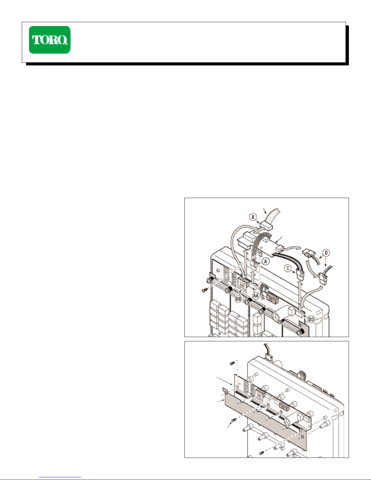
1. Remove both cabinet doors. Place the satellite power supply
switch in the Off ( I ) position.
Note: The function of the 24V detect PCBA (shown in
Figure 1) is now incorporated into the new distribution
PCBA. Therefore, the 24V detect PCBA is no longer
required and should be removed prior to installing the
distribution PCBA included in this kit.
The 24V detect PCBA is an optional component and may
not be installed in the satellite. Procedural steps 2 through
5 cover the removal of this component. If the satellite
does not have the 24V detect component, disregard steps
2 through 5 and continue at step 6.
2. Locate the 24V detect PCBA and remove all of the attached
cables (
A, B, C& D).
3. Remove the single #6 tap screw used to secure the 24V detect
PCBA to the chassis. Carefully lift the 24V detect PCBAupwards,
unplugging it from the distribution PCBA socket.
4. Plug the ribbon cable connector (
B) into socket (BB).
Note: The ribbon cable connector (B) is not keyedand can
be installed incorrectly. The blue orientation stripe on the ribbon
cable
must be on the left side (when facing the cable/socket).
5. Plug the 2-wire (black and white) connector (D) into
socket (
DD).
6. Working now on the back of the black plastic chassis, position
the new distribution PCBA onto the chassis, guiding the PCBA
onto the 5 plastic bosses as shown in Figure 2. Secure with
two #6 screws installed in the center and left side screw hole
locations.
7. Install the insulator card over the bottom portion of the distribution
PCBA. Use the two outside plastic bosses to guide the card
into position. Secure the card with a #6 screw installed in the
right side screw hole location. See
Figure 2.
Network LTC Plus Satellite, Distribution PCBA Kit, 89-9747
Installation Instructions
Figure 1
Orientation Stripe
24V Detect PCBA
Figure 2
Insulator
Card
#6 Screw
Distribution
PCBA
Page 2
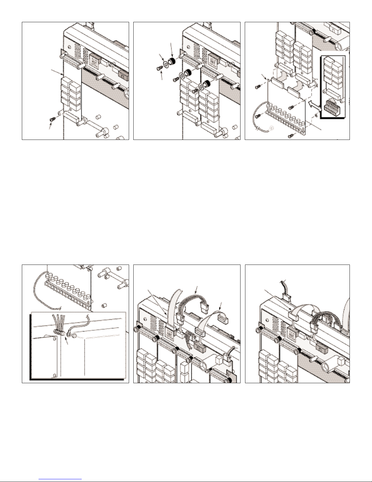
Note: Output modules must be installed from left to right without open connector positions in between. The timing mechanism
will not recognize any output module installed to the right of an open connector position. The middle 11-pin connector is not
used on the back distribution board and is not considered an open connector position.
8. Starting at the left side of the distribution PCBA, carefully install an 8-station output module onto the first 16-pin module connector.
Make sure the socket at the top of the module is correctly aligned with the connector pins before pressing the module into position.
Secure the module with a single #6 screw as shown in
Figure 3. Install up to three additional output modules in this manner.
Note: Do not force the module into position on the distribution PCBA. If the connector pins are correctly aligned, the module
will slide into position with only slight resistance.
9. Install a plastic retainer, flat washer and #6 screw (supplied with the output module) on each of the upper bosses to secure
the output module(s) to the distribution PCBA. See
Figure 4.
10.Plug the optional 16-output surge module into the receptacles of the two 8-station output modules and secure with four #6 screws
as shown in Figure 5. If installing the optional 8-station terminal block, simply plug it into the output module receptacle as shown
in the inset in
Figure 5.
11.Route the ground wire from the 16-output surge module to the ground buss (located to the left of the power supply housing).
Install the ring terminal onto the stud and secure with an #8-32 self-locking nut (provided). See Figure 6.
CAUTION: Each 16-output surge module must be grounded to enable the surge suppression components to function.
Surge damage can occur if the controller is not properly grounded.
12.Install the jumper wire assemblies to the front distribution PCBA as shown in Figure 7.
Note: The ribbon cable blue orientation stripe must be on the left side (when facing the cable/socket).
13.Install the jumper wire assemblies to the back distribution PCBA as shown in Figure 8. This will require making a twist in the
jumper cables to install correctly.
14.Place the power supply switch in the On (
O) position.
Form Number 373-0029 Rev. A
© 1999 The Toro Company, Irrigation Division
Figure 3
Output
Module
Figure 5
Figure 4
#6 Screw
Retainer
#6 Screw
16-Output
Surge
Module
8-Station
Terminal
Block
4-Wire Jumper
Orientation
Stripe
Orientation
Stripe
Ribbon
Jumper
(Power Supply
Housing)
Ground
Buss
Flat Washer
Figure 6
Figure 7
Figure 8
(Front View)
(Back View)
 Loading...