

Page 1
107cmRecycler
XLSSeries™LawnTractor
ModelNo.79176
Installation
LooseParts
Usethechartbelowtoverifythatallpartshavebeenshipped.
FormNo.3370-775RevA
®
Kit
InstallationInstructions
ProcedureDescription
1
2
3
4
5
1
PreparingtheMower
Qty.
Nopartsrequired
Upperbafe
Bolt(5/16x5/8inch)
Flange-headnut(5/16inch)
Bolt(1/4x5/8inch)
Locknut(1/4inch)
Kickerplate3
Phillipsheadscrew(#8x5/8inch)
Dischargecover1
Bolt(1/4x2-1/2inches)
Capnut(1/4inch)
Recyclingdecal1Instalthedecal.
–
1
3
3
4
4
6
2
2
•Ifanyoftheholeshavefastenersinthem,
removethefasteners.
•Ifanyoftheholeshaverivetsinthem,drillout
thecenterofeachrivetwitha3/16inch(5mm)
drillbitanddiscardtherivet.
Preparethemower.
Installtheupperbafe.
Installthekickerplates.
Installthedischargecover.
Use
NoPartsRequired
Procedure
1.Stoptheengine,removetheignitionkeyandpull
thesparkplugwire.
2.RemovethemowerasdescribedinyourOperator's
Manual.
3.Turnthemowerupsidedown.
4.Removethemowerbladesasdescribedinyour
Operator'sManual.
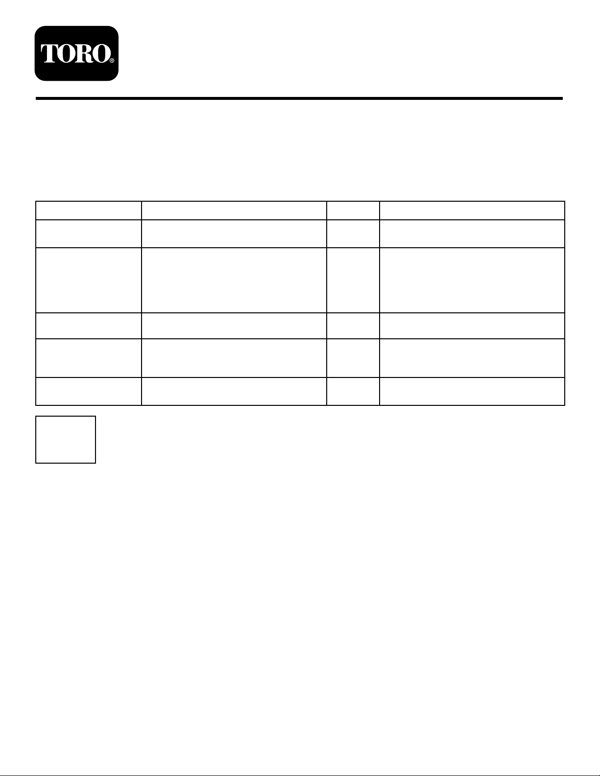
5.Locatetheholesillustratedin
asfollows:
©2011—TheT oro®Company
8111LyndaleAvenueSouth
Bloomington,MN55420
Figure1andproceed
Registeratwww.Toro.com.
OriginalInstructions(EN)
PrintedintheUSA.
AllRightsReserved
Page 2

Figure1
1.Holesformountingtheupperbafe
2.Holesformountingthekickers
3.Locknut(3/8inch)fromthedischargechuteretainingrod
4.Cutoffbafe
6.Removethelocknut(3/8inch)securingthedischarge
chuteretainingrodtothemower(Figure1).Save
itforlateruse.
7.Ifthedeckhasacutoffbafeinstalleditmustbe
removedbeforetheRecyclerkitcanbeinstalled
Figure1).Retainthecutoffbafeforconverting
(
backtosidedischarge.
Figure2
1.Upperbafe3.Bolts(1/4x5/8inch)
2.Bolts(5/16x5/8inch)4.Locknut(3/8inch),install
onthedischargechute
retainingrod
2
InstallingtheUpperBafe
Partsneededforthisprocedure:
1
Upperbafe
3
Bolt(5/16x5/8inch)
3
Flange-headnut(5/16inch)
4
Bolt(1/4x5/8inch)
4
Locknut(1/4inch)
Procedure
1.Installtheupperbafe,tabspointedintothemower
asshownin
dischargechuterodcomethroughthebafehole.
Figure2.Ensurethatthethreadsofthe
2.Installthelocknutremovedpreviouslyoverthe
threadsofthedischargechuteretainingrodtosecure
thebafetothemower(
Figure2).
3.Installthreebolts(5/16x5/8inch)andthreeange
nuts(5/16inch)throughthesideofthemowerat
eachtabasshowninFigure2.Installthefasteners
withthenutsontheinside.
4.Installfourbolts(1/4x5/8inch)inthebafeand
upthroughthetopofthemowerandsecureitwith
fourlocknuts(1/4inch)asshownin
Figure2.
2
Page 3
3
4
InstallingtheKickerPlates
Partsneededforthisprocedure:
3Kickerplate
6
Phillipsheadscrew(#8x5/8inch)
Procedure
1.Alignthethreekickerplateswithholestowardthe
topofthemower(
kickersmustbefaceinward.
Figure3).Thelongslopeofthe
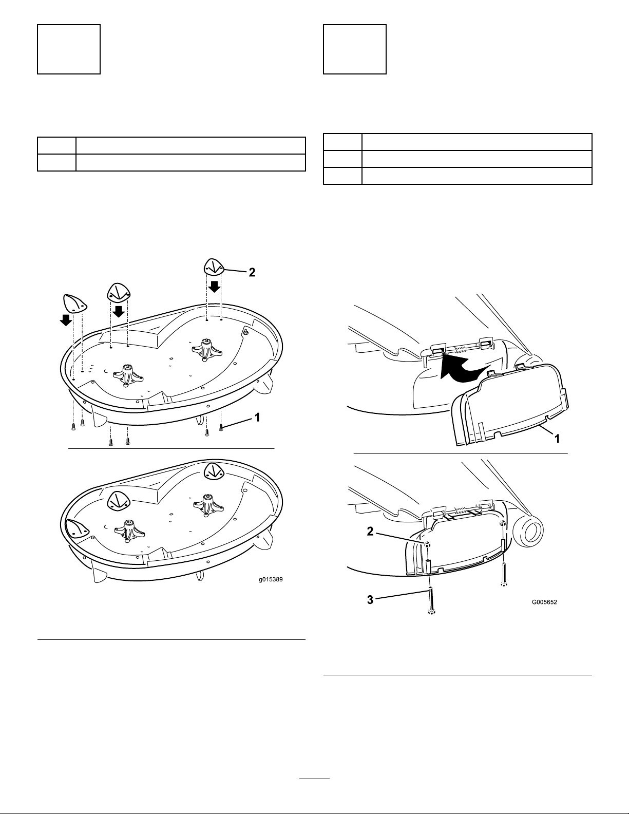
InstallingtheDischargeCover
Partsneededforthisprocedure:
1Dischargecover
2
Bolt(1/4x2-1/2inches)
2
Capnut(1/4inch)
Procedure
1.Liftthegrassdeectorandslidethetabsontop
ofthedischargecoverunderthegrassdeector
retainingrod.Rotatethedischargecoverdownover
theopening,andontothelowerlipofthemower
Figure4).
(
Figure3
1.Kickerplate
2.SecuretheplatestothemowerusingsixPhillipshead
screws(#8x5/8inch).Thescrewscomeupthrough
thetopofthemowerandintotheplates(
2.Phillipsheadscrew(#8x
5/8inch)
Figure3).
Figure4
1.Dischargecover
2.Capnut(1/4inch)
2.Securethedischargecovertothelowerlipofthe
mowerwithtwobolts(1/4x2-1/2inches)andtwo
capnuts(1/4inch)asshownin
Note:Donotovertightenthenuts;thiscould
distortthecoverandcausebladecontact.
3
3.Bolt(1/4x2-1/2inches)
Figure4.
Page 4

Operation
5
InstallingtheDecal
Partsneededforthisprocedure:
1Recyclingdecal
Procedure
Installthedecalonleftsideofthemower(Figure5).
ConvertingtoSide-discharge
Operation
DANGER
Withoutthegrassdeector,dischargecover,or
completegrasscatcherassemblymountedin
place,youandothersareexposedtobladecontact
andthrowndebris.Contactwithrotatingmower
blade(s)andthrowndebriswillcauseinjuryor
death.
•Neverremovethegrassdeectorfromthe
mowerbecausethegrassdeectorroutes
materialdowntowardtheturf.Ifthe
grassdeectoriseverdamaged,replaceit
immediately.
•Neverputyourhandsorfeetunderthemower.
•Nevertrytoclearthedischargeareaormower
bladesunlessyoumovethepowertakeoff
(PTO)todisengageandturntheignitionkey
tooff.Alsoremovethekeyandpullthewire
offthesparkplug(s).
1.Recyclerdecal
Figure5
Note:Tousethemowerinsidedischargemode,
onlythedischargecovermustberemoved.Mounting
hardwaremustbeinstalledinopenholes.
1.Stoptheengineandremovetheignitionkey.
2.Removethe2boltsandnutsthatsecurethe
dischargecovertothemower.
3.Removethedischargecover.
4.Ifthemoweroriginallyhadacutoffbafe,install
itnow.
5.Lowerthegrassdeectoroverthedischarge
opening.
Important:Ensurethemowerhasahinged
grassdeectorthatdispersesclippingstothe
sideanddowntowardtheturf,whileinside
dischargemode.
Tomulchgrassclippings,installthedischargecover
intotheopeninginthesideofthemower;referto
InstallingtheDischargeCover.
OperatingTips
SelectingtheProperHeight-of-Cut
SettingtoSuittheConditions
Removeapproximatelyoneinchornomorethat1/3
ofthegrassbladewhencutting.Inexceptionallylush
4
Page 5

anddensegrassyoumayhavetoraisetheheight-of-cut
settinganothernotchorconverttosidedischargeor
baggingoperations.
MowinginExtremeConditions
Airisrequiredtocutandrecutgrassclippingsinthe
mowerhousing,sodonotsettheheight-of-cuttoolow
ortotallysurroundthehousingbyuncutgrass.Always
haveonesideofthemowerhousingfreefromuncut
grass,allowingairtobedrawnintohousing.When
makinganinitialcutthroughthecenteroftheuncut
area,operatethemachineataslowerspeedandbackup
ifthemowerstartstoclog.
MowingattheProperIntervals
Undernormalconditionsyou'llneedtomowevery
4-5days.However,grassgrowsatdifferentratesat
differenttimes.Thus,inordertomaintainthesame
height-of-cut,whichisagoodpractice,you'llneedto
cutmorefrequentlyinearlyspring;asthegrassgrowth
rateslowsinmidsummer,cutonlyevery8-10days.
Ifyouareunabletomowforanextendedperioddue
totheweatherconditionsorotherreasons,convertto
sidedischargeorbaggingoptionsormowrstwiththe
height-of-cutatahighlevel;thenmowagain2-3days
laterwithalowerheightsetting.
AlwaysMowwithSharpBlades
Asharpbladecutscleanlyandwithouttearingor
shreddingthegrassbladelikeadullblade.Tearingand
shreddingcausesthegrasstoturnbrownattheedges
whichimpairsgrowthandincreasessusceptibilityto
disease.
CleaningAfterOperating
Toensureoptimumperformance,cleantheunderside
ofthemowerhousing.Ifresidueisallowedtobuildup
inmowerhousing,cuttingperformancewilldecrease.
5
Page 6

Notes:
6
Page 7

Notes:
7
Page 8

 Loading...