

Page 1

Form No. 3354-171 Rev A
48in Vac-Bagger
For TimeCutter Z Riding Mowers
Model No. 79166 —Serial No. 260000001 and Up
Register your product at www.Toro.com Original Instructions (EN)
Page 2
Contents
Introduction
R ead this infor mation carefully to lear n ho w to operate
and maintain y our product properly and to a v oid injur y
and product damag e . Y ou are responsible for operating
the product properly and safely .
Y ou ma y contact T oro directly at www .T oro .com for
product and accessor y infor mation, help finding a
dealer , or to register y our product.
W henev er y ou need ser vice , g en uine T oro par ts , or
additional infor mation, contact an A uthorized Ser vice
Dealer or T oro Customer Ser vice and ha v e the model
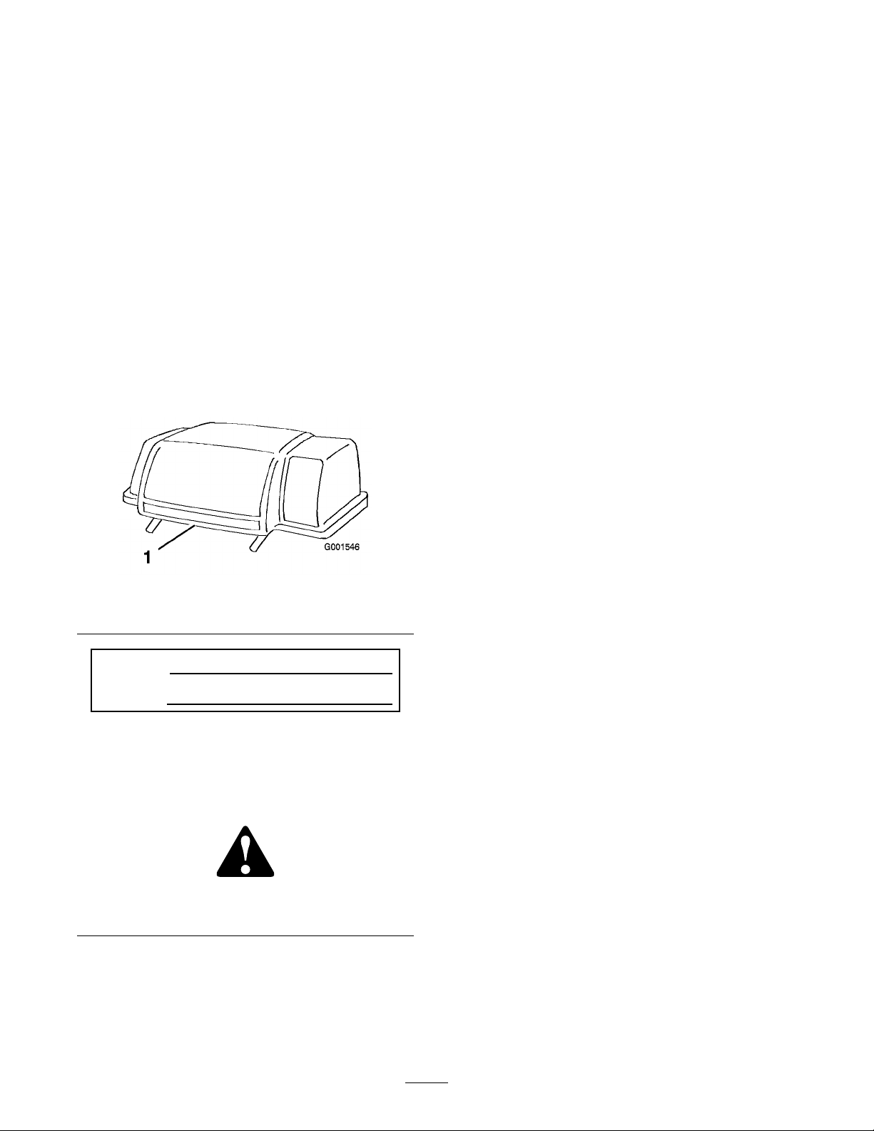
and serial n umbers of y our product ready . Figure 1
identifies the location of the model and serial n umbers
on the product. W rite the n umbers in the space
pro vided.
Figure 1
1. Model and serial number location
Introduction . . . . . . . . . . . . . . . . . . . . . . . . . . . . . . . . . . . . . . . . . . . . . . . . . . . . . . . . . 2
Safety . . . . . . . . . . . . . . . . . . . . . . . . . . . . . . . . . . . . . . . . . . . . . . . . . . . . . . . . . . . . . . . . . . 3
Safety and Instr uctional Decals . . . . . . . . . . . . . . . . . . . . . . . . 3
Setup . . . . . . . . . . . . . . . . . . . . . . . . . . . . . . . . . . . . . . . . . . . . . . . . . . . . . . . . . . . . . . . . . . . 5
1 R emo ving the Disc harg e Chute . . . . . . . . . . . . . . . . . . . . . . 6
2 Installing the Grass Baffle . . . . . . . . . . . . . . . . . . . . . . . . . . . . . 6
3 Installing the Blo w er Pi v ot Suppor t . . . . . . . . . . . . . . . . . 6
4 Installing the Blo w er Pulley . . . . . . . . . . . . . . . . . . . . . . . . . . . 7
5 Installing the Blo w er . . . . . . . . . . . . . . . . . . . . . . . . . . . . . . . . . . . . . 8
6 Installing the Belt Co v ers . . . . . . . . . . . . . . . . . . . . . . . . . . . . . . 9
7 Installing the Lev eling Brac k ets . . . . . . . . . . . . . . . . . . . . 10
8 Assembling the Bag g er . . . . . . . . . . . . . . . . . . . . . . . . . . . . . . . 10
9 Installing the W eight . . . . . . . . . . . . . . . . . . . . . . . . . . . . . . . . . . . 10
10 Installing the Bag g er Suppor t
Assembly . . . . . . . . . . . . . . . . . . . . . . . . . . . . . . . . . . . . . . 11
11 Installing the Bag g er Assembly . . . . . . . . . . . . . . . . . . . 11
12 Mounting the Disc harg e T ube . . . . . . . . . . . . . . . . . . . . 12
Operation . . . . . . . . . . . . . . . . . . . . . . . . . . . . . . . . . . . . . . . . . . . . . . . . . . . . . . . . . . 14
Emptying the Grass Bags . . . . . . . . . . . . . . . . . . . . . . . . . . . . . . . 14
Clearing Obstr uctions from the Bag g er . . . . . . . . . . . . 14
R emo ving the Grass Collector . . . . . . . . . . . . . . . . . . . . . . . . 15
Operating Tips . . . . . . . . . . . . . . . . . . . . . . . . . . . . . . . . . . . . . . . . . . . . 19
Maintenance . . . . . . . . . . . . . . . . . . . . . . . . . . . . . . . . . . . . . . . . . . . . . . . . . . . . . . . 21
R ecommended Maintenance
Sc hedule(s) . . . . . . . . . . . . . . . . . . . . . . . . . . . . . . . . . . . 21
Inspecting the Bag g er Attac hment . . . . . . . . . . . . . . . . . . 21
Inspecting the Mo w er Blades . . . . . . . . . . . . . . . . . . . . . . . . . 22
Caring for the Grass Bags . . . . . . . . . . . . . . . . . . . . . . . . . . . . . . 22
Cleaning the Bag g er Attac hment . . . . . . . . . . . . . . . . . . . . . 22
Storag e . . . . . . . . . . . . . . . . . . . . . . . . . . . . . . . . . . . . . . . . . . . . . . . . . . . . . . . . . . . . . . 23
Storing the Bag g er Attac hment . . . . . . . . . . . . . . . . . . . . . . . 23
Model No.
Serial No.
T his man ual identifies potential hazards and has
safety messag es identified b y the safety aler t symbol
( Figure 2 ), whic h signals a hazard that ma y cause
serious injur y or death if y ou do not follo w the
recommended precautions .
Figure 2
1. Safety alert symbol
T his man ual uses 2 other w ords to highlight
infor mation. Impor tant calls attention to special
mec hanical infor mation and Note emphasizes g eneral
infor mation w or th y of special attention.
© 2005—The Toro® Company
8111 Lyndale Avenue South
Bloomington, MN 55420
Contact us at www.Toro.com.
2
Printed in the USA.
All Rights Reserved
Page 3
Safety
Safety and Instructional Decals
Safety decals and instr uctions are easily visible to the operator and are located near any
area of potential dang er . R e place any decal that is damag ed or lost.
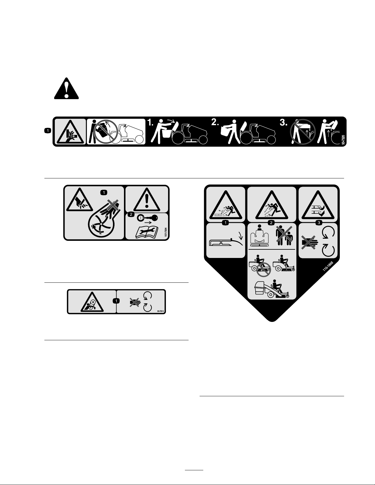
93-7320
1. Crushing hazard of hand—do not remove the whole bagger from the machine; open the bagger top and then remove the bag(s)
from the bagger. Do not remove the bagger top when it is closed; open the bagger top and then remove it.
Molded into blower housing
1. Cutting hazard of hand—do not place your hand into the
impeller housing.
2. Warning—remove the ignition key and read the instructions
before servicing or performing maintenance.
Molded into the blower belt cover
1. Entanglement hazard, belt—stay away from moving parts.
1. Thrown object hazard,
mower—keep the deector
in place.
2. Thrown object
hazard—Keep bystanders
a safe distance from the
machine; Do not operate
the without deector or
grass collection system in
place.
110-1868
3. Cutting/dismemberment
of hand or foot—stay away
from moving parts.
3
Page 4
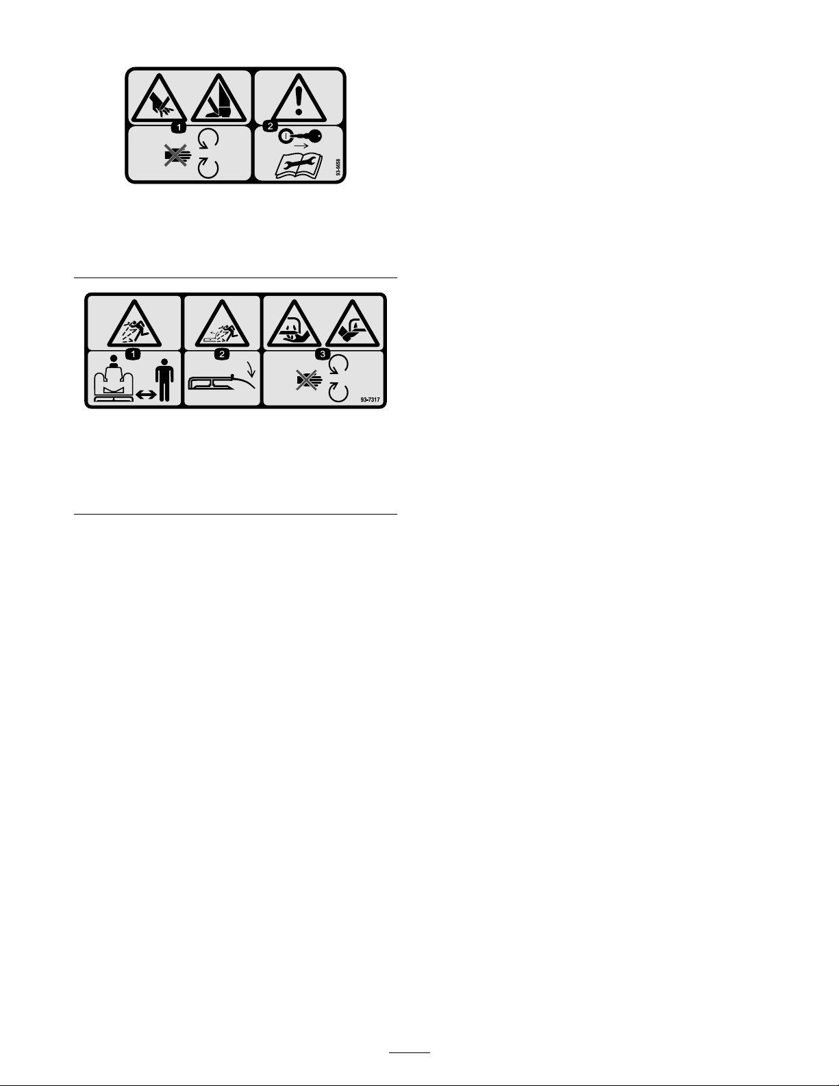
Molded into the blower belt cover
1. Cutting hazard of hand or foot—stay away from moving
parts.
2. Warning—remove the ignition key and read the instructions
before servicing or performing maintenance.
93-7317
1. Thrown object hazard—keep bystanders a safe distance from
the machine.
2. Thrown object hazard, mower—keep the deector in place.
3. Cutting/dismemberment of hand or foot—stay away from
moving parts.
4
Page 5

Setup
Loose Parts
Use the chart below to verify that all parts have been shipped.
Step
1
2
3
4
5
6
No parts required
Bafe, 48 inch
Carriage bolt, (5/16 x 3/4 inch)
Washer, (5/16 inch)
Locknut, (5/16 inch)
Pivot support
Bolt (5/16 x 3/4 inch)
Locknut (5/16 inch)
Jam nut (3/8 inch)
Washer (3/8 inch)
Double pulley
Blower assembly
Belt
Belt cover bracket
Screw (1/4 x 3/8 inch)
Mower belt cover
Screw (1/4 x 1/2 inch)
Blower belt cover
Bolt (1/4 x 5/8 inch)
Locknut (1/4 inch)
Description
Qty.
–
1
2
1
2
1
1
1
1
1
1
1
1
1
3
1
2
1
2
2
Remove the discharge chute.
Install the grass bafe.
Install the blower pivot support.
Install the blower pulley.
Install the blower.
Instal the belt covers.
Use
7
8
9
10
11
12
Leveling brackets
Bolt (1/4 x 3/4 inch)
Locknut (1/4 inch)
Weight
Bolt (3/8 x 2-1/4 inch)
Washer (3/8 inch)
Locknuts (3/8 inch)
Bagger support assembly
Bolt (3/8 x 1 inch)
Washer (3/8 inch)
Locknut (3/8 inch)
Bagger 1
Grass Bag 2
No parts required
2
2
2
1
2
4
2
1
4
4
4
–
Install the leveling brackets.
Assemble the Bagger
Instal the weight.
Install the bagger support assembly.
Install the bagger assembly.
Mount the discharge tube
Note: Deter mine the left and right sides of the mac hine from the nor mal operating position.
Note: T he installation of this attac hment requires the infor mation found in the Operator’ s Manual ; y ou
should ha v e the man ual at hand to reference during the installation.
5
Page 6
Step
Step
1
Removing the Discharge
Chute
No Parts Required
Procedure
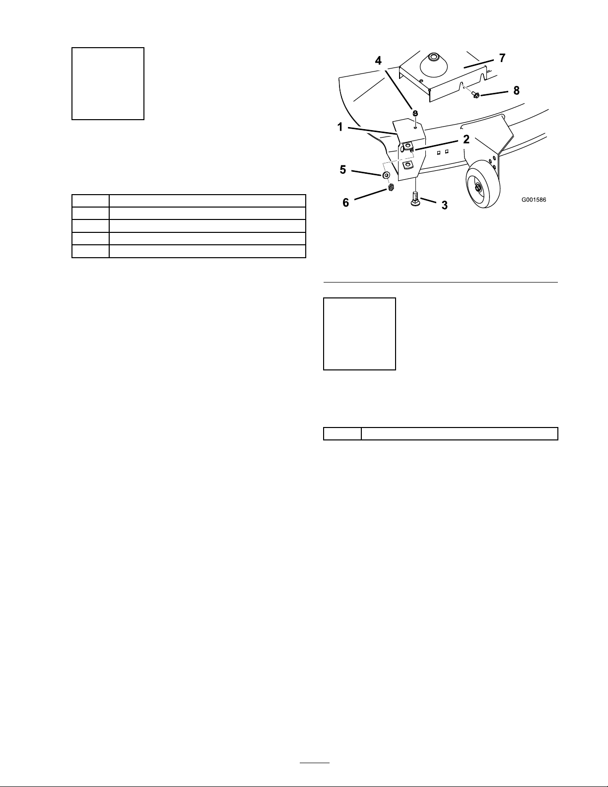
1. R emo v e the bolt and n ut securing the disc harg e
c hute to the mo w er dec k ( Figure 3 ). R emo v e
the disc harg e c hute and spring assembly .
R etain all par ts for future installation.
2
Installing the Grass Bafe
Parts needed for this step:
1
Bafe, 48 inch
2
Carriage bolt, (5/16 x 3/4 inch)
1
Washer, (5/16 inch)
2
Locknut, (5/16 inch)
Procedure
Install the 48 inc h g rass baffle to the existing g rass
baffle with tw o car riag e bolts (5/16 x 3/4 inc h),
w asher (5/16 inc h) and tw o loc kn uts (5/16 inc h)
as sho wn in Figure 4 . Use the w asher in the larg er ,
upper hole when installing the 48 inc h baffle to
the existing baffle .
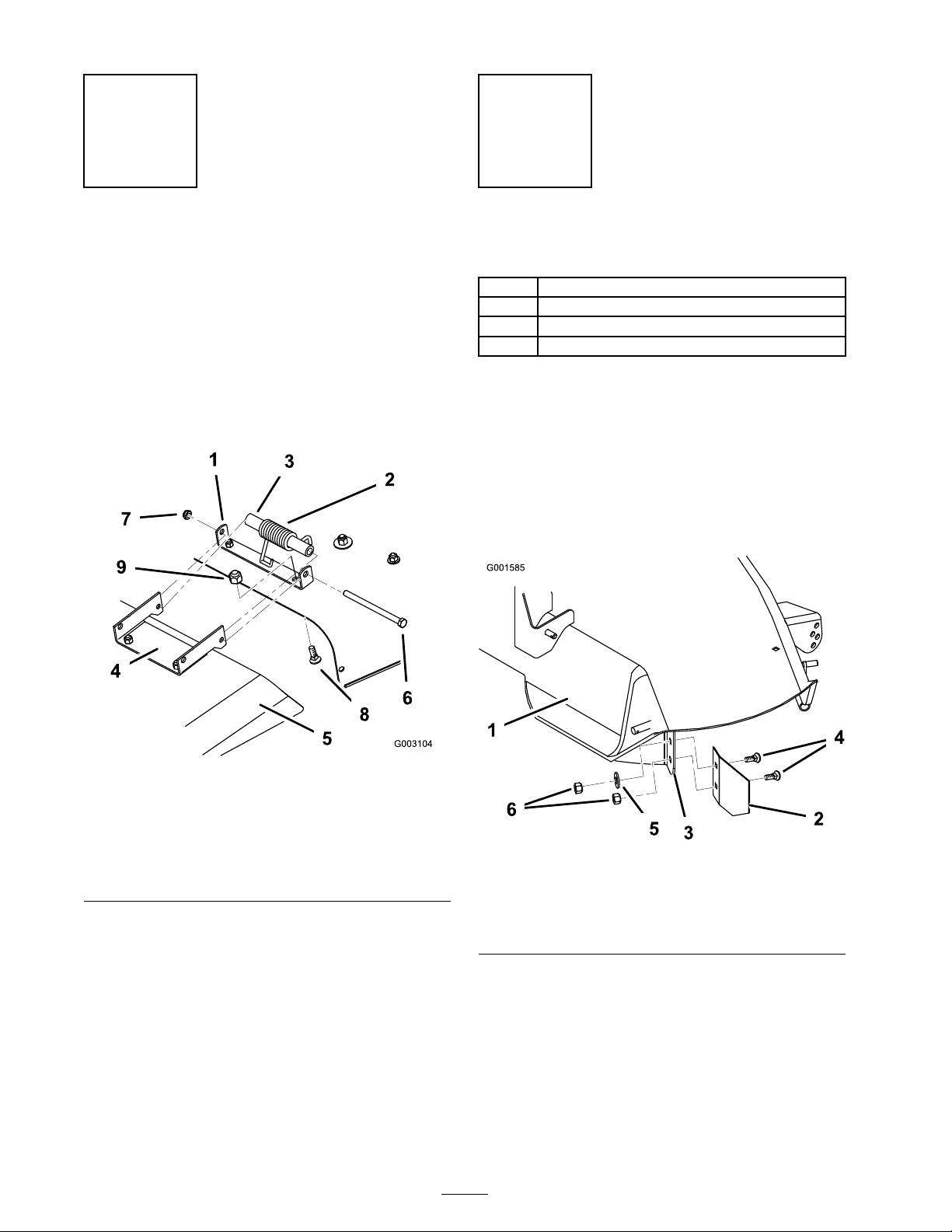
Figure 3
1. Mount bracket, discharge
chute
2. Spring, hooked ends down 7. Locknut
3. Spacer
4. Discharge chute, bracket
5. Discharge chute
6. Bolt
8. Carriage bolt (5/16 x 5/8
inch)
9. Locknut (5/16 inch)
2. R emo v e the tw o car riag e bolts and loc kn uts
securing the mounting brac k et to the mo w er
( Figure 3 ). R emo v e the mounting brac k et.
3. Install the tw o car riag e bolts and loc kn uts into
the open mo w er dec k holes . R etain all par ts
for future installation.
6
1. Mower deck
2. 48 inch bafe
3. Grass bafe, existing
Figure 4
4. Carriage bolt (5/16 x 3/4
inch)
5. Washer (5/16 inch)
6. Locknut (5/16 inch)
Page 7
Step
3
Installing the Blower Pivot
Support
Parts needed for this step:
1
Pivot support
1
Bolt (5/16 x 3/4 inch)
1
Locknut (5/16 inch)
1
Jam nut (3/8 inch)
1
Washer (3/8 inch)
Procedure
1. Pivot support
2. Threaded stud
3. Bolt (5/16 x 3/4 inch)
4. Flange nut (5/16 inch)
Figure 5
5. Washer (3/8 inch)
6. Jam nut (3/8 inch)
7. Mower belt cover
8. Fastener
1. Slide the pi v ot suppor t o v er the threaded
stud w elded to the front of the mo w er near
the disc harg e opening . Use the inside slot on
the pi v ot suppor t so that the pi v ot suppor t is
closest to the disc harg e opening ( Figure 5 ).
Note: If necessar y , remo v e any hardw are
in the mo w er dec k interfering with the pi v ot
suppor t. R etain all hardw are .
2. Align the pi v ot suppor t parallel with the front
cur v ed edg e of the mo w er dec k and tight up
ag ainst the top of the mo w er . ( Figure 5 ).
3. Secure the pi v ot suppor t to the mo w er with a
bolt (5/16 x 3/4 inc h) and a flang e n ut (5/16
inc h) ( Figure 5 ).
4. Place a jam n ut (3/8 inc h) and w asher (3/8
inc h) sn ug onto the stud. Do not o v er tighten
the jam n ut ( Figure 5 ).
5. R emo v e the mo w er belt co v er from the right
side pulley ( Figure 5 ).
Note: Sa v e all par ts and hardw are for use
when remo ving the blo w er .
Step
4
Installing the Blower Pulley
Parts needed for this step:
1
Double pulley
Procedure
1. Pull on the mo w er idler assembly to release
belt tension and remo v e the blade dri v e belt
from the right side pulley; refer to the mac hine
Operator’ s Manual for instr uctions .
Note: Bloc k the blade with a piece of w ood
to stop it from tur ning while y ou remo v e the
pulley n ut. If the blade slips , hold the hex
por tion of the spindle with a wrenc h.
2. R emo v e the n ut and loc k w asher from the
right-hand blade spindle . R emo v e the single
pulley .
Note: W hen the n ut is remo v ed the shaft
is free to drop out of the spindle . Be sure to
suppor t the spindle and blade from the bottom
side .
3. Slide the new double pulley onto the spindle
shaft with the small pulley , facing up . Secure
7
Page 8
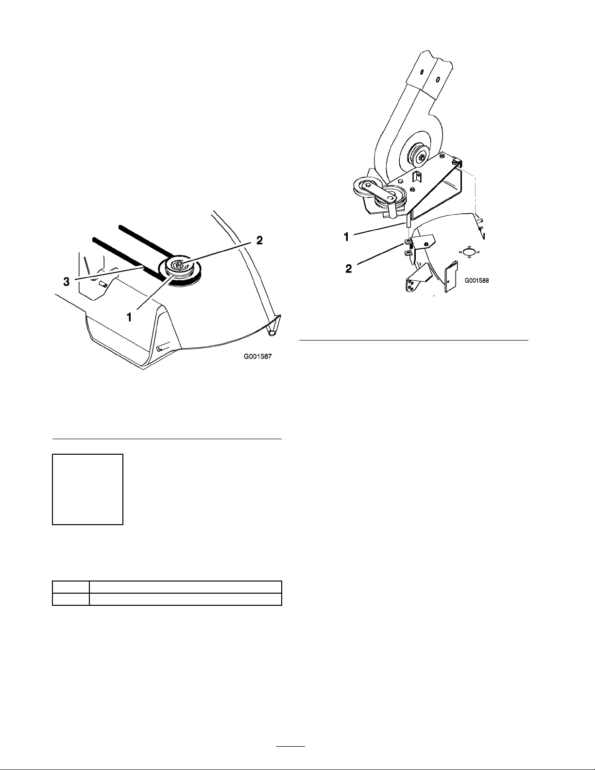
it with the previously remo v ed 5/8 inc h loc k
w asher and n ut ( Figure 6 ).
4. Tighten the n ut to 50-75 ft. lb . (68-101 N ⋅ m).
5. Install the existing mo w er belt onto the bottom
pulley ( Figure 6 ).
6. Pull on the mo w er idler assembly and install
the existing mo w er belt b y rotating it onto the
idler pulley .
Note: Chec k that mo w er belt is properly
located on the idler and pulleys .
Figure 7
1. Pivot pin 2. Pivot support
1. New double pulley, small
pulley on top.
2. Lock washer and nut, 5/8
inch
Step
5
Installing the Blower
Parts needed for this step:
1
Blower assembly
1
Belt
Procedure
Figure 6
3. Mower belt
3. Open the latc h and swing the blo w er out a w a y
from the mo w er , install the blo w er belt around
the idler and blo w er pulleys as sho wn Figure 8 .
Install the other end of the belt o v er the blo w er
dri v e pulley on the mo w er spindle .
1. Install the mo w er to the mac hine; refer to
Operator’ s Manual .
2. Install the blo w er b y lo w ering the pi v ot pin
into the pi v ot suppor t ( Figure 7 ).
8
Page 9

Figure 8
1. Idler pulley bracket and
pulley
2. Top (wide) side of belt
against bottom pulley
3. "V" side of belt into top
pulley groove
4. With the belt installed, swing the blo w er to w ard
the mo w er until the blo w er latc h loc ks o v er the
pin at the bac k of the mo w er ( Figure 9 ).
Important: Y ou may ha v e to lift the
blo w er slightl y f or the latch to close.
Ensur e that the latch operates smoothl y
and closes completel y .
Step
6
Installing the Belt Covers
Parts needed for this step:
1
Belt cover bracket
3
Screw (1/4 x 3/8 inch)
1
Mower belt cover
2
Screw (1/4 x 1/2 inch)
1
Blower belt cover
2
Bolt (1/4 x 5/8 inch)
2
Locknut (1/4 inch)
Procedure
1. Attac h the belt co v er brac k et to the mo w er
dec k with tw o (1/4 x 3/8 inc h) screws
( Figure 10 ).
2. Attac h the front of the mo w er belt co v er
loosely to the belt co v er brac k et with tw o (1/4
x 1/2 inc h) screws . Attac h the bac k of the
mo w er belt co v er loosely to the mo w er dec k
with a (1/4 x 3/8 inc h) screw ( Figure 10 ).
Note: Do not tighten the screws as
adjustment m ust be made later .
1. Blower latch
Figure 9
2. Pin
Figure 10
1. Belt cover bracket 3. Mower belt cover
2. Screw (1/4 x 3/8 inch) 4. Screw (1/4 x 1/2 inch)
9
Page 10

3. Mount the blo w er belt co v er using tw o (1/4 x
5/8 inc h) bolts and tw o (1/4 inc h) loc kn uts
( Figure 11 ). Tighten the loc kn uts slightly so
light drag is felt on the belt co v er when it is
tilted upw ard. T he co v er m ust close freely
when assembled.
Figure 11
1. Blower belt cover 3. Locknut ,1/4 inch
2. Bolt, 1/4 x 5/8 inch 4. Mower belt cover
Figure 12
1. Hole leveling bracket 2. Washer and hairpin cotter
2. Chec k the mo w er lev el front-to-rear and
side-to-side; refer to the Operator’ s Manual for
instr uctions .
Step
8
4. Adjust the mo w er belt co v er b y sliding it so
the blo w er belt co v er just touc hes the blo w er ,
but still opens freely . Tighten the mo w er belt
co v er mounting screws .
Step
7
Installing the Leveling
Brackets
Parts needed for this step:
2
Leveling brackets
Procedure
1. R e place the tw o left side mo w er lev eling
brac k ets (slotted) with tw o new lev eling
brac k ets (hole) as sho wn in Figure 12 . Secure
them with the existing w ashers and hair pin
cotters .
Note: Sa v e the slotted lev eling brac k et for
future side disc harg e operation.
Assembling the Bagger
Parts needed for this step:
2
Bolt (1/4 x 3/4 inch)
2
Locknut (1/4 inch)
Procedure
If necessar y , install the bag g er frame to the co v er .
Attac h the frame assembly to the bag g er co v er
with tw o bolts (1/4 x 3/4 inc h) and tw o loc kn uts
(1/4 inc h) ( Figure 13 ).
Figure 13
1. Frame assembly 3. Bolt, 1/4 x 3/4 inch
2. Bagger cover
4. Locknut (1/4 inch)
10
Page 11

Step
Step
9
Installing the Weight
Parts needed for this step:
1
Weight
2
Bolt (3/8 x 2-1/4 inch)
4
Washer (3/8 inch)
2
Locknuts (3/8 inch)
Procedure
T he ba g ger adds a lot of w eight to the r ear
of the machine and may cause an unsta ble
condition which could r esult in a loss of
contr ol.
Install the fr ont w eight.
Attac h the w eight to the front of the tractor with
tw o bolts (3/8 x 2-1/4 inc h), four w ashers (3/8
inc h), and tw o loc kn uts (3/8 inc h) as sho wn in
Figure 14 .
10
Installing the Bagger
Support Assembly
Parts needed for this step:
1
Bagger support assembly
4
Bolt (3/8 x 1 inch)
4
Washer (3/8 inch)
4
Locknut (3/8 inch)
Procedure
Attac h the bag g er suppor t assembly to the
mac hine frame with four bolts (3/8 x 1 inc h), four
w ashers (3/8 inc h), and four loc kn uts (3/8 inc h)
as sho wn in Figure 15 .
Figure 14
1. Footrest frame
2. Bolt (3/8 x 2-1/4 inch) 5. Nut (3/8 inch)
3. Front weight
4. Washer (3/8 inch)
11
1. Machine frame
2. Support
3. Bolt (3/8 x 1 inch)
Figure 15
4. Washer (3/8 inch)
5. Locknut (3/8 inch)
Page 12

Step
11
Installing the Bagger
Assembly
Parts needed for this step:
1 Bagger
2 Grass Bag
Procedure
1. Carefully lift the bag g er top and slide it onto
the quic k attac h brac k et ( Figure 16 ). T he
bag g er top is easier to install if tw o people
w ork tog ether .
2. Install the bags b y sliding the bag frame hooks
onto the retaining brac k ets ( Figure 17 ).
Figure 17
1. Bag frame hook 2. Retaining bracket
Figure 16
1. Bagger top
If y ou r emo v e the spring-loaded ba g ger
top when it is closed (in the do wn
position), the top may suddenl y fly open
and y ou or someone else may be br uised,
pinched, or injur ed in another w ay .
2. Quick attach bracket
3. Lo w er the bag g er top onto the bags . T hen
push do wn on both bag retainer handles until
they loc k on the bag frame ( Figure 18 ).
Figure 18
1. Bagger top
2. Bag retainer handles
Al w ays open (raise) the ba g ger top
bef or e y ou r emo v e or install it on the
quick-attach brack et.
12
Page 13

Step
12
Mounting the Discharge
Tube
No Parts Required
Procedure
1. Inser t the upper end of the disc harg e tube
into the bag g er top . Slide the lo w er end of
the disc harg e tube into the blo w er disc harg e
extension opening ( Figure 19 ).
2. Hook the r ubber latc h onto the knob
( Figure 19 ).
Figure 19
1. Blower discharge extension 3. Rubber latch
2. Discharge tube 4. Knob
13
Page 14

Operation
Note: Deter mine the left and right sides of the
mac hine from the nor mal operating position.
T o a v oid per sonal injur y , f ollo w these
pr ocedur es:
• Become f amiliar with all operating and
safety instr uctions in the Operator’ s
Man ual f or the mo w er bef or e using this
attachment.
• Nev er r emo v e the discharge tube, ba gs,
ba g ger top , or the chute while the engine
is r unning .
• Al w ays shut the engine of f and w ait f or
all mo ving par ts to stop bef or e clearing
an obstr uction fr om the ba g ging system.
• Nev er do maintenance or r epair s while
the engine is r unning .
3. Compress debris into the bags . With both
hands , lift up on the bag and unhook it from
the retaining brac k et. Empty the bag . R e peat
the procedure for the other bag .
4. Install the bags b y sliding the bag frame hooks
onto the retaining brac k ets ( Figure 21 ).
Emptying the Grass Bags
Be careful when lifting or handling a g rass bag that
is full. T o empty the g rass bags:
1. Stop the mo w er , set the parking brak e , and
diseng ag e the blade control switc h (PTO).
Stop the engine and remo v e the ignition k ey .
2. Pull up on both bag retainer handles until they
unloc k from the bag frame ( Figure 20 ). Open
(raise) the bag g er top .
Figure 21
1. Bag frame hook 2. Retaining bracket
5. Lo w er the bag g er top onto the bags . T hen
push do wn on both bag retainer handles until
they loc k on the bag frame .
Clearing Obstructions from
the Bagger
1. Stop the mo w er , shift into neutral, set the
parking brak e , diseng ag e the blade control
switc h, stop the engine , and remo v e the
ignition k ey . W ait for all mo ving par ts to stop .
2. Chec k the g rass bags and empty them if they
are full.
3. R emo v e and se parate the disc harg e tube and
c hute from the bag g er top and mo w er . Using
a stic k or similar object, carefully remo v e
and clear the obstr uction from the mo w er ,
disc harg e tube , c hute , and the bag g er top .
1. Bagger top
4. After y ou remo v e the obstr uction, install the
complete bag g er system and resume operation.
Figure 20
2. Bag retainer handles
14
Page 15

Removing the Grass
Collector
An unco v er ed discharge opening could
allo w the la wn mo w er to thr o w objects in
the operator or bystander’ s dir ection and
r esult in serious injur y . Also, contact with
the blade could occur .
Nev er operate the la wn mo w er unless y ou
install a co v er plate, a mulch plate, or a g rass
chute and catcher .
Removing the Discharge Tube
1. Unhook the r ubber latc h onto the knob
( Figure 22 ).
2. Slide the lo w er end of the disc harg e tube out
of the blo w er disc harg e extension opening
( Figure 22 ). Pull the upper end of the disc harg e
tube out of the bag g er top .
Figure 23
1. Bagger top
2. Bag retainer handles
If y ou r emo v e the spring-loaded ba g ger
top when it is closed (in the do wn
position), the top may suddenl y fly open
and y ou or someone else may be br uised,
pinched, or injur ed in another w ay .
Figure 22
1. Blower discharge extension 3. Rubber latch
2. Discharge tube 4. Knob
Removing the Bagger
1. Raise the bag g er top and remo v e the g rass
bags from the bag frame ( Figure 23 ).
Al w ays open (raise) the ba g ger top
bef or e y ou r emo v e or install it on the
quick-attach brack et.
2. Carefully lift the bag g er top and slide it off the
quic k attac h brac k et ( Figure 24 ). T he bag g er
top is easier to remo v e if tw o people w ork
tog ether .
15
Page 16

Figure 24
1. Bagger top
2. Quick attach bracket
3. Store all bag g er par ts in a con v enient place .
Removing the Belt Covers
Figure 26
1. Belt cover bracket 3. Mower belt cover
2. Screw (1/4 x 3/8 inch) 4. Screw (1/4 x 1/2 inch)
1. R emo v e the blo w er belt co v er b y remo ving
tw o (1/4 inc h) loc kn uts and (1/4 x 5/8 inc h)
bolts ( Figure 25 ).
Figure 25
1. Blower belt cover
2. Bolt (1/4 x 5/8 inch)
3. Locknut (1/4 inch)
4. Mower belt cover
2. R emo v e the mo w er belt co v er and belt co v er
brac k et from the right side pulley ( Figure 26 ).
Note: Sa v e all par ts and hardw are for use
when installing blo w er .
Removing the Blower from the Mower
1. Open the latc h and swing the blo w er out a w a y
from the mo w er , remo v e the blo w er belt from
the mo w er pulley ( Figure 27 ).
Figure 27
1. Idler pulley bracket and
pulley
2. Top (wide) side of belt
against bottom pulley
3. "V" side of belt into top
pulley groove
2. R emo v e the blo w er b y lifting the pi v ot pin out
of the pi v ot suppor t ( Figure 28 ).
16
Page 17

Figure 28
1. Pivot pin 2. Pivot support
Removing the Blower Pulley from the
Mower
1. Pull on mo w er idler assembly to release belt
tension and remo v e blade dri v e belt from right
side pulley ( Figure 29 ).
Note: Bloc k blade with a piece of w ood to
stop it from tur ning while y ou remo v e the
pulley n ut. If blade slips hold hex por tion of
spindle with a wrenc h.
Figure 29
1. New double pulley, small
pulley on top.
2. Lock washer and nut, 5/8
inch
3. Mower belt
3. Slide the single pulley onto the spindle shaft.
Secure with previously remo v ed loc k w asher
and n ut ( Figure 30 ).
4. Tighten the n ut to 50-75 ft. lb . (68-101 N ⋅ m).
5. Install the existing mo w er belt b y rotating it
onto the pulley ( Figure 30 ).
Note: Chec k that mo w er belt is properly
located on idler and pulleys .
2. R emo v e n ut and loc k w asher from right hand
blade spindle ( Figure 29 ). R emo v e double
pulley .
Note: W hen n ut is remo v ed the shaft is free
to drop out of the spindle . Be sure to suppor t
the spindle and blade from the bottom side .
Figure 30
1. Single groove pulley 3. Mower belt
2. Lock washer and nut
Removing the Blower Pivot Support
1. R emo v e the pi v ot suppor t and pi v ot brac k et
from the mo w er ( Figure 31 ).
Note: Sa v e all par ts and hardw are for use
when installing blo w er .
17
Page 18

2. Install the previously remo v ed hardw are in the
open hole of the mo w er for safety ( Figure 31 ).
3. Install the mo w er belt co v er using existing
hardw are ( Figure 31 ).
Figure 31
1. Pivot support
2. Threaded stud
3. Bolt (5/16 x 3/4 inch)
4. Flange nut (5/16 inch)
5. Washer (3/8 inch)
6. Jam nut (3/8 inch)
7. Mower belt cover
8. Fastener
1. Mower deck
2. 48 inch bafe
3. Grass bafe, existing
Install the Discharge Chute
Figure 32
4. Carriage bolt (5/16 x 3/4
inch)
5. Washer (5/16 inch)
6. Locknut (5/16 inch)
Open holes in the mo w er expose y ou
and other s to thr o wn de bris which could
cause injur y .
Nev er operate the mo w er without
hard w ar e mounted in all holes in the
mo w er .
Removing the Grass Bafe
R emo v e the tw o car riag e bolts (5/16 x 3/4 inc h),
one w asher (5/16 inc h) and tw o loc kn uts (5/16
inc h), as sho wn in Figure 32 , securing the 48 inc h
baffle to the existing g rass baffle . R emo v e the 48
inc h g rass baffle .
W ithout the g rass deflector , discharge
co v er , or complete g rass catcher assembl y
mounted in place, y ou and other s ar e
exposed to blade contact and thr o wn de bris.
Contact with the r otating mo w er blade(s)
and thr o wn de bris will cause injur y or death.
• Nev er r emo v e the g rass deflector fr om
the mo w er because the g rass deflector
r outes material do wn to w ard the turf.
If the g rass deflector is ev er dama ged,
r eplace it immediatel y .
• Nev er put y our hands or feet under the
mo w er .
• Nev er tr y to clear the discharge ar ea or
mo w er blades unless y ou mo v e the blade
contr ol s witch (PT O) to Of f and r otate
the ignition k ey to Of f. Also r emo v e the
k ey and pull the wir e of f of the spar k
plug(s).
1. Install the mounting brac k et onto the mo w er
with car riag e bolts (5/16 x 5/8 inc h) and
loc kn uts (5/16 inc h) as sho wn in Figure 33 .
2. Install the disc harg e c hute onto the mo w er
( Figure 33 ) in betw een the mounting brac k ets .
18
Page 19

Figure 33
1. Mount bracket, discharge
chute
2. Spring, hooked ends down 7. Locknut
3. Spacer
4. Discharge chute, bracket
5. Discharge chute
6. Bolt
8. Carriage bolt (5/16 x 5/8
inch)
9. Locknut (5/16 inch)
Replacing the Leveling Brackets
1. R e place the tw o , left side mo w er lev eling
brac k ets (hole) with tw o slotted lev eling
brac k ets ( Figure 34 ). Secure them with the
existing w ashers and hair pin cotters .
Note: Sa v e the (hole) lev eling brac k et for use
when the blo w er is installed.
Figure 34
1. Slotted leveling bracket 2. Washer and hairpin cotter
3. Align the disc harg e c hute with the holes in the
brac k ets and the spring and spacer in the space
betw een the brac k ets and abo v e the deflector
( Figure 33 ).
4. Place the spring and spacer so that the hook ed
ends of the spring are pointing do wn, with one
end contacting on the mo w er dec k and the
other o v er the deflector ( Figure 33 ).
5. Secure the deflector to the mo w er brac k et
with the bolt. T he bolt should pass through
the g rass deflector , spring, spacer , and
brac k ets . Secure the assembly with the loc kn ut
( Figure 33 ).
Note: It ma y be helpful to press do wn near
the end of the bolt with a 9/16 inc h open end
wrenc h to align the bolt with the second hole
on the mo w er brac k et and g rass deflector .
6. Lift the disc harg e c hute and c hec k that it is
spring loaded and pi v ots freely to the full do wn
position.
Important: T he discharge chute must
be spring loaded in the do wn position. Lift
the deflector up to test that it snaps to the
full do wn position.
2. Chec k the mo w er lev el front-to-rear and
side-to-side; refer to the Operator’ s Manual for
instr uctions .
Operating Tips
Tips for Bagging
Size
R emember that the mo w er is long er and wider
with this attac hment installed. By tur ning too
shar ply in confined places y ou ma y damag e the
attac hment.
Trimming
Alw a ys trim with the left side of the mo w er . Do
not trim with the right side of the mo w er because
y ou could damag e the bag g er’ s c hute and disc harg e
tube .
Cutting Height
Do not set the mo w er cutting height too lo w
because long g rass sur rounding the mo w er can
prev ent air from g etting under the mo w er and
entering the bag ging system. If enough air doesn ’ t
g et under the mo w er , the bag ging system will plug .
19
Page 20

Cutting Frequency
Cut the g rass often, especially when it g ro ws
rapidly . Y ou will ha v e to cut y our g rass twice if
it g ets ex cessi v ely long .
Cutting Technique
F or best la wn appearance , be sure to slightly
o v erlap the mo w er into the previously cut area.
T his helps reduce the load on the engine and
reduces the c hance of plug ging the c hute and
disc harg e tube .
Using Bag Liners
Although not required, bags ma y be inser ted
into eac h g rass bag to collect clippings and mak e
disposal more con v enient ( Figure 35 ). If y ou use a
bag liner , remo v e the filled g rass bag and close the
top of the liner . T hen pull the liner out the g rass
bag or tur n the bag upside do wn while holding the
handle on the bottom of the g rass bag, allo wing
the liner to slide out.
As the ba g ger fills, extra w eight is added to
the back of the machine. If y ou stop and
star t suddenl y on hills, y ou may lose steering
contr ol or the machine may tip .
• Do not star t or stop suddenl y when going
uphill or do wnhill. A v oid uphill star ts.
• If y ou do stop the machine when going
uphill, disenga ge the blade contr ol
s witch. T hen back do wn the hill using a
slo w speed.
• Do not change speeds or stop on slopes.
Bagging Long Grass
Bag ging Long Grass Ex cessi v ely long g rass is
hea vy and ma y not be propelled completely into
the g rass bags . If this happens , the disc harg e tube
and c hute ma y plug . T o a v oid plug ging the bag ging
system, mo w the g rass at a high height of cut, then
lo w er the mo w er to y our nor mal cutting height
and re peat the bag ging process .
Figure 35
1. Cloth grass bag
2. Bag (liner)
Bagging Speed
Most often y ou will bag with the mo w er throttle
in the F ast position and dri v e at a nor mal g round
speed. Ho w ev er , in extremely dr y and dusty g rass ,
y ou ma y w ant to slightly reduce the throttle speed
and increase the g round speed of the mo w er . T he
bag ging system ma y plug if y ou dri v e too fast and
the engine speed g ets too slo w . On hills it ma y
be necessar y to slo w the mo w er g round speed.
T his helps maintain the engine speed and bag ging
efficiency . Mo w do wnhill whenev er possible .
Bagging Wet Grass
Alw a ys tr y to cut g rass when it is dr y because y our
la wn will ha v e a neat appearance . If y ou m ust
cut w et g rass , use the con v entional side disc harg e
feature of the mo w er . Sev eral hours later , when
the clippings are dr y , install the complete bag g er
attac hment and v acuum up the g rass clippings .
Signs of Plugging
As y ou are bag ging, a small amount of g rass
clippings nor mally blo w out the front of the
mo w er . An ex cessi v e amount of clippings blo wing
out indicates that the bags are full or the system
is plug g ed.
20
Page 21

Maintenance
Note: Deter mine the left and right sides of the mac hine from the nor mal operating position.
Recommended Maintenance Schedule(s)
Maintenance Service
Interval
After the rst 10
operating hours
Before each use or daily
Before storage
Maintenance Procedure
• Inspect the bagger
• Clean the bagger
• Inspect the bagger
• Clean the bagger
If y ou lea v e the k ey in the ignition s witch, someone could accidentl y star t the engine and
seriousl y injur e y ou or other bystander s.
R emo v e the k ey fr om the ignition and disconnect the wir e fr om the spar k plug bef or e y ou do
an y maintenance. Set the wir e aside so that it does not accidentall y contact the spar k plug .
De bris built up in the engine compar tment, if not r emo v ed, could be ignited by a hot engine.
A fir e in the engine compar tment could can bur n y ou and other s and can dama ge pr oper ty .
• Bef or e using and while the engine is cool, check f or de bris in the engine compar tment.
• K eep the machine fr ee of g rass, lea v es, or other de bris build-up .
• Clean up oil or fuel spilla ge and fuel soak ed de bris.
• Allo w the machine to cool bef or e storing .
Inspecting the Bagger
Attachment
Inspect the bag g er attac hment after the first 10
hours of operation, and monthly thereafter .
1. Chec k the c hute , disc harg e tube , and the
bag g er top . R e place these par ts if they are
crac k ed or brok en.
2. Tighten all n uts , bolts , and screws .
3. Inspect the g rass bags for deterioration.
Y ou or bystander s could be sev er el y
injur ed by flying de bris or thr o wn objects
that may pass thr ough tor n, w or n, or
deteriorated g rass ba gs.
• F r equentl y check the g rass ba gs
f or holes, rips, w ear , and other
deterioration.
• Do not w ash the g rass ba gs.
• If the ba g has deteriorated, install
new g rass ba gs supplied by the
man uf actur er of this ba g ger
attachment.
21
Page 22

Inspecting the Mower Blades
Inspect the mo w er blades regularly and whenev er
a blade strik es a foreign object.
If the blades are badly w or n or damag ed, install
new blades . R efer to y our mo w er or mo w er
Operator’ s Manual for complete blade maintenance .
Caring for the Grass Bags
W ashing the g rass bags is not recommended.
T o prev ent rapid deterioration of the bag material,
store the bags where they will dr y completely after
eac h use .
Cleaning the Bagger
Attachment
1. After eac h use , remo v e and w ash the inside
and outside of the bag g er top , disc harg e tube ,
c hute , and the underside of the mo w er , using
w ater spra yed from a g arden hose . Use a mild
automoti v e deterg ent to remo v e stubbor n dir t.
2. Mak e sure y ou remo v e matted g rass from all
par ts .
3. After w ashing, let all of the par ts dr y
thoroughly . Do not w ash the g rass bags .
22
Page 23

Storage
Storing the Bagger
Attachment
1. Clean the bag g er attac hment; refer to Cleaning
the Bag g er Attac hment.
2. Inspect the bag g er attac hment for damag e;
refer to Inspecting the Bag g er Attac hment.
3. Mak e sure the g rass bags are empty and
thoroughly dr y .
4. Store the bag g er in a clean, dr y place , out of
direct sunlight. T his protects the plastic par ts
and extends the life of the bag g er . If y ou
m ust store the bag g er outside , co v er it with a
w eather proof co v er .
23
Page 24

Consumer
TimeCutter
A Two-Year Full Warranty (Limited Warranty for Commercial Use)
The Toro Total Coverage Guarantee
Conditions and Products Covered
The Toro Company and its afliate, Toro Warranty Company,
pursuant to an agreement between them, jointly promise to
repair any Toro Product used for normal residential purposes*
if defective in materials or workmanship. The following time
periods apply from the date of purchase:
Products Warranty Period
All TimeCutter Mowers and
Attachments
All Batteries 1 year full warranty
This warranty covers both the cost of parts and labor, and
transportation within a fteen mile radius of the servicing dealer.
This warranty applies to all consumer TimeCutter Mowers and
their attachments.
N o r m a l r e s i d e n t i a l p u r p o s e s m e a n s u s e o f t h e p r o d u c t o n t h e s a m e l o t a s y o u r h o m e . U s e
a t m o r e t h a n o n e l o c a t i o n i s c o n s i d e r e d c o m m e r c i a l u s e , a n d t h e c o m m e r c i a l u s e w a r r a n t y
w o u l d a p p l y .
2 year full warranty
Limited Warranty for Commercial Use
Toro Consumer Products and attachments used for commercial,
institutional, or rental use are warranted against defects in
materials or workmanship for the following time periods from the
date of purchase:
Products Warranty Period
Air Cooled Gas Engines 90 day limited warranty
All other items 30 day limited warranty
Instructions for Obtaining Warranty Service
If you think that your Toro Product contains a defect in materials
or workmanship, follow this procedure:
1. Contact any Toro Authorized or Master Service Dealer
to arrange service at their dealership. To locate a dealer
convenient to you, refer to the Yellow Pages of your
telephone directory (look under “Lawn Mowers") or access
our website at www.Toro.com. U.S. Customers may also
call toll free: 866-854-9035 to use our 24-hour Toro dealer
locator system.
2. Bring the product and your proof of purchase (sales receipt)
to the Service Dealer.
If for any reason you are dissatised with the Service Dealer’s
analysis or with the assistance provided, contact us at:
Customer Care Department, Consumer Division
Toro Warranty Company
8111 Lyndale Avenue South
Bloomington, MN 55420-1196
Toll Free: 866-216-6029 (U.S. customers)
Toll Free: 866-216-6030 (Canada customers)
Owner Responsibilities
You must maintain your Toro Product by following the
maintenance procedures described in the operator’s manual.
Such routine maintenance, whether performed by a dealer or by
you, is at your expense.
Items and Conditions Not Covered
There is no other express warranty except for special emission
system coverage on some products. This express warranty does
not cover:
• Cost of regular maintenance service or parts, such as lters,
fuel, lubricants, tune-up parts, blade sharpening, brake and
clutch adjustments.
• Any product or part which has been altered or misused
or required replacement or repair due to normal wear,
accidents, or lack of proper maintenance.
• Repairs necessary due to improper fuel, contaminants in the
fuel system, or failure to properly prepare the fuel system
prior to any period of non-use over three months.
• Pickup and delivery charges for distances beyond a fteen
mile radius from an Authorized Toro Service Dealer.
All repairs covered by this warranty must be performed by an
Authorized Toro Service Dealer using Toro approved replacement
parts.
General Conditions
Repair by an Authorized Toro Service Dealer is your sole remedy
under this warranty.
Neither The Toro® Company nor Toro Warranty Company is liable
for indirect, incidental or consequential damages in connection
with the use of the Toro Products covered by this warranty,
including any cost or expense of providing substitute equipment
or service during reasonable periods of malfunction or non-use
pending completion of repairs under this warranty.
Some states do not allow exclusions of incidental or consequential
damages, or limitations on how long an implied warranty lasts,
so the above exclusions and limitations may not apply to you.
This warranty gives you specic legal rights, and you may also
have other rights which vary from state to state.
Countries Other than the United States or Canada
Customers who have purchased Toro products exported from the United States or Canada should contact their Toro Distributor
(Dealer) to obtain guarantee policies for your country, province, or state. If for any reason you are dissatised with your Distributor’s
service or have difculty obtaining guarantee information, contact the Toro importer. If all other remedies fail, you may contact us
at Toro Warranty Company.
374-0061 Rev A
 Loading...