

Page 1

FormNo.3353-488RevC
44inVac-Bagger
forTimeCutterZXRidingMowers
ModelNo.79163—SerialNo.260000001andUp
Registeratwww.T oro.com.OriginalInstructions(EN)
Page 2
Contents
Introduction
Readthisinformationcarefullytolearnhowtooperate
andmaintainyourproductproperlyandtoavoidinjury
andproductdamage.Youareresponsibleforoperating
theproductproperlyandsafely.
YoumaycontactTorodirectlyatwww .Toro.comfor
productandaccessoryinformation,helpndinga
dealer,ortoregisteryourproduct.
Wheneveryouneedservice,genuineToroparts,or
additionalinformation,contactanAuthorizedService
DealerorToroCustomerServiceandhavethemodel
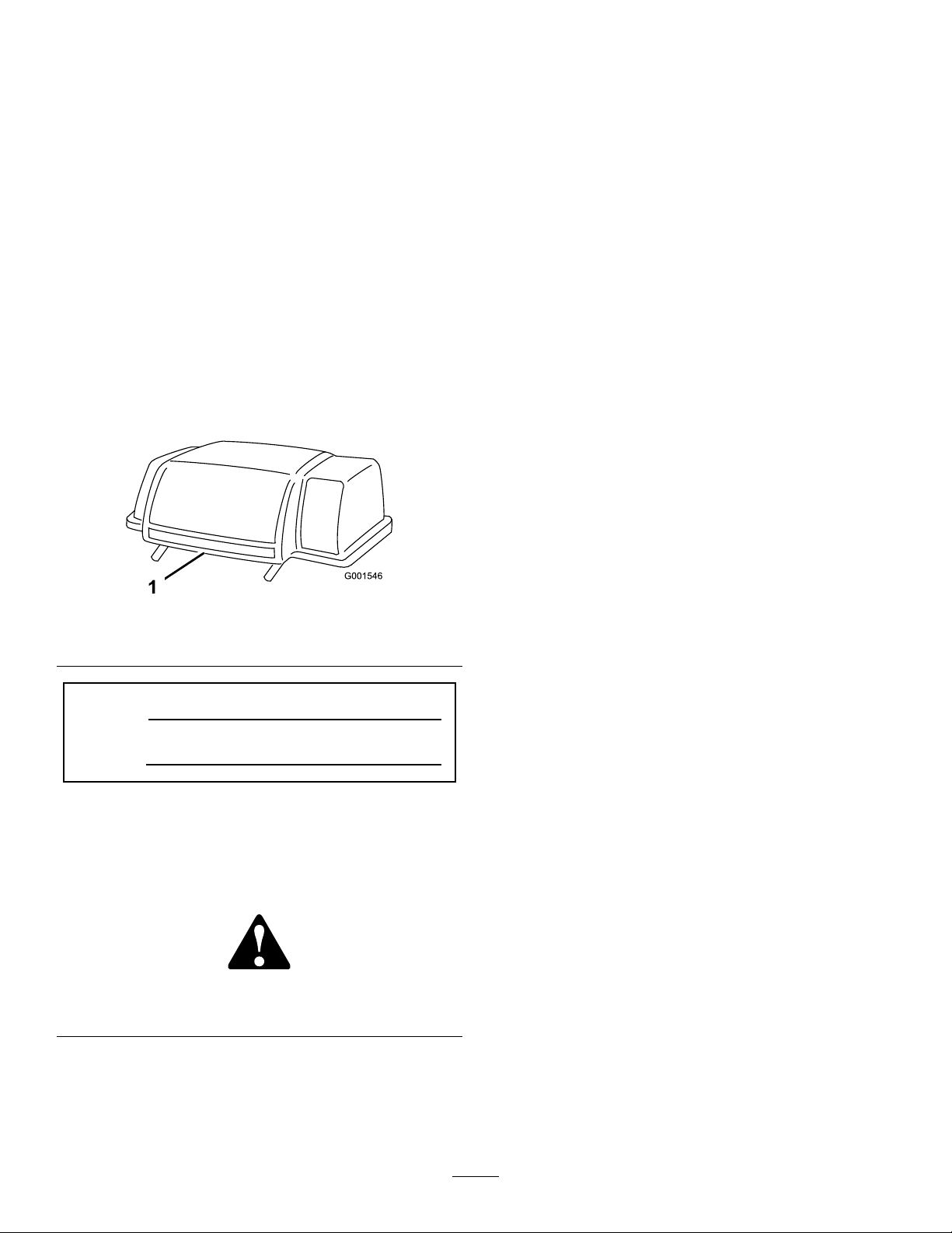
andserialnumbersofyourproductready .Figure1
identiesthelocationofthemodelandserialnumbers
ontheproduct.Writethenumbersinthespace
provided.
Figure1
1.Modelandserialnumberlocation
ModelNo.
SerialNo.
Thismanualidentiespotentialhazardsandhas
safetymessagesidentiedbythesafetyalertsymbol
(Figure2),whichsignalsahazardthatmaycauseserious
injuryordeathifyoudonotfollowtherecommended
precautions.
Introduction.................................................................2
Safety...........................................................................3
SafetyandInstructionalDecals.............................3
Setup............................................................................5
1RemovingtheRecycler®Bafes........................6
2InstallingtheHi-liftBlades.................................6
3RemovingtheDischargeChute..........................7
4InstallingtheGrassBafe..................................8
5InstallingtheBlowerPivotSupport....................8
6InstallingtheBlowerPulley................................9
7InstallingtheBlower..........................................9
8InstallingtheBeltCovers.................................10
9InstallingtheLevelingBracket..........................11
10AssemblingtheBagger...................................11
11InstallingtheW eight......................................12
12InstallingtheExhaustDeector(for
Kawasakienginesonly)...................................12
13InstallingtheBaggerSupport
Assembly.......................................................13
14InstallingtheBaggerAssembly.......................14
15MountingtheDischargeTube........................15
Operation...................................................................16
UsingtheFullBagTester....................................16
EmptyingtheGrassBags....................................16
ClearingObstructionsfromtheBagger...............17
RemovingtheVac-Bagger..................................17
OperatingTips...................................................22
Maintenance...............................................................23
RecommendedMaintenanceSchedule(s)................23
InspectingtheBaggerAttachment......................23
InspectingtheMowerBlades..............................23
CaringfortheGrassBags...................................24
CleaningtheBaggerAttachment.........................24
Storage.......................................................................24
StoringtheBaggerAttachment...........................24
Figure2
1.Safetyalertsymbol
Thismanualuses2otherwordstohighlightinformation.
Importantcallsattentiontospecialmechanical
informationandNoteemphasizesgeneralinformation
worthyofspecialattention.
©2008—TheToro®Company
8111LyndaleAvenueSouth
Bloomington,MN55420
Contactusatwww.Toro.com.
2
PrintedintheUSA.
AllRightsReserved
Page 3
Safety
SafetyandInstructionalDecals
Safetydecalsandinstructionsareeasilyvisibletotheoperatorandarelocatednearanyareaof
potentialdanger.Replaceanydecalthatisdamagedorlost.
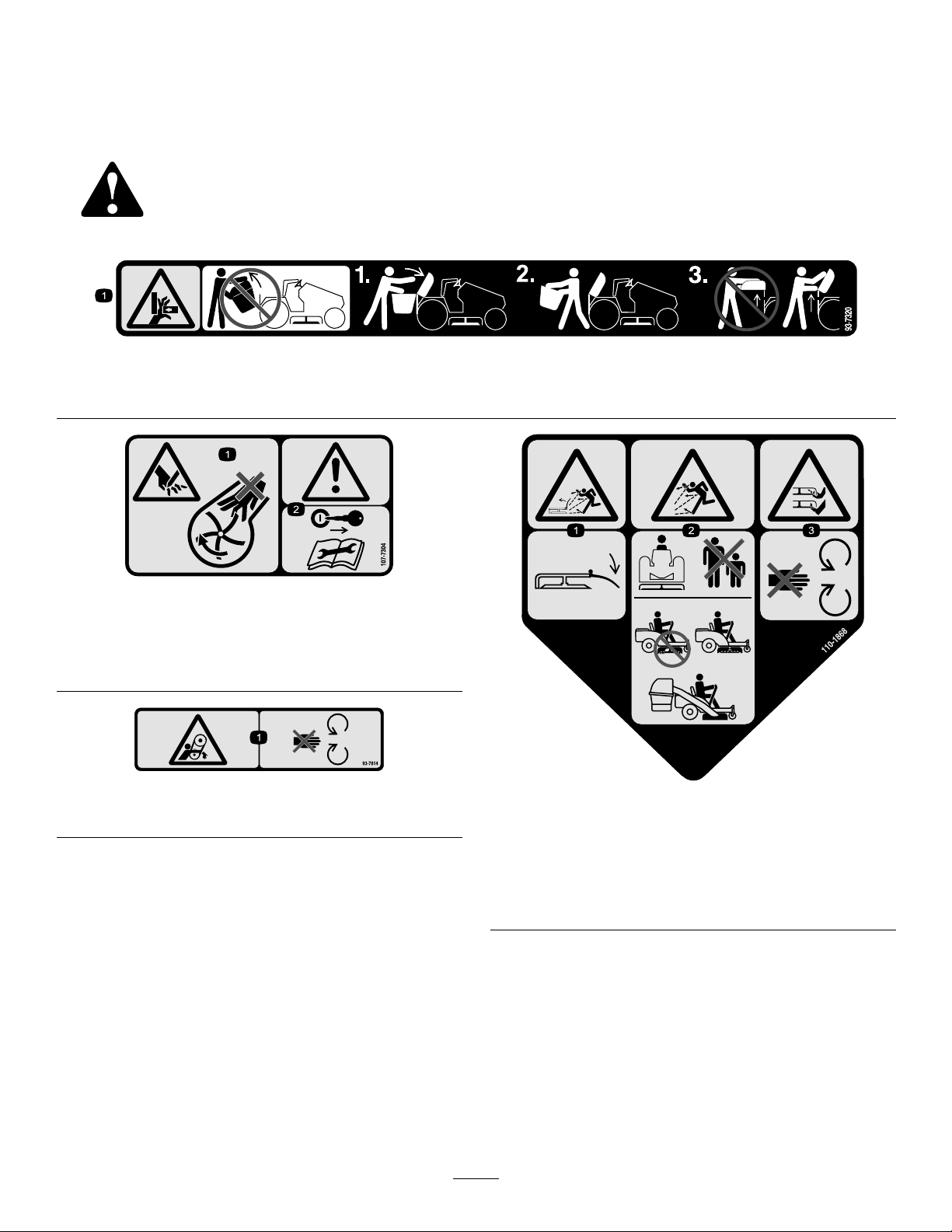
93-7320
1.Crushinghazardofhand—donotremovethewholebaggerfromthemachine;openthebaggertopandthenremovethebag(s)
fromthebagger .Donotremovethebaggertopwhenitisclosed;openthebaggertopandthenremoveit.
Moldedintoblowerhousing
1.Cuttinghazardofhand—donotplaceyourhandintothe
impellerhousing.
2.Warning—removetheignitionkeyandreadtheinstructions
beforeservicingorperformingmaintenance.
Moldedintotheblowerbeltcover
1.Entanglementhazard,belt—stayawayfrommovingparts.
110-1868
1.Thrownobjecthazard,mower—keepthedeectorinplace.
2.Thrownobjecthazard—Keepbystandersasafedistance
fromthemachine;Donotoperatethewithoutdeectoror
grasscollectionsysteminplace.
3.Cutting/dismembermentofhandorfoot—stayawayfrom
movingparts.
3
Page 4
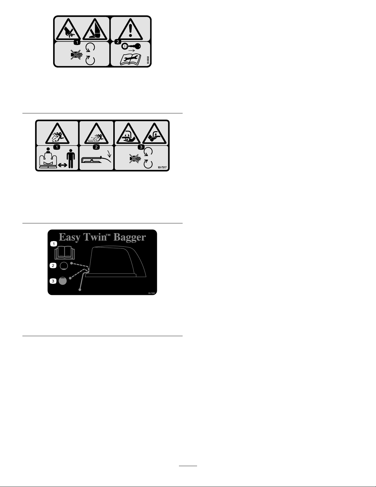
Moldedintotheblowerbeltcover
1.Cuttinghazardofhandorfoot—stayawayfrommoving
parts.
2.Warning—removetheignitionkeyandreadtheinstructions
beforeservicingorperformingmaintenance.
93-7317
1.Thrownobjecthazard—keepbystandersasafedistance
fromthemachine.
2.Thrownobjecthazard,mower—keepthedeectorinplace.
3.Cutting/dismembermentofhandorfoot—stayawayfrom
movingparts.
93-7329
1.ReadtheOperator’sManual.
2.Thebagisnotfull.
3.Thebagisfull.
4
Page 5

Setup
LooseParts
Usethechartbelowtoverifythatallpartshavebeenshipped.
ProcedureDescription
1
2
3
4
5
6
7
8
Nopartsrequired
Hi-liftblades
Nopartsrequired
Reargrassbafe
Grassring
Carriagebolt,(5/16x7/8inch)
Locknut,(5/16inch)
Carriagebolt,(5/16x2-1/2inch)
Spacer
Bolt(1/4x3/4inch)
Locknut(1/4inch)
Pivotsupport1
Pivotbracket1
Carriagebolt,(5/16x7/8inch)
Carriagebolt,(5/16x4-1/2inch)
Spacertube
Locknut(5/16inch)
Washer(1 1/32inch)
Beltcover1
Blowerpulley1
Screw(1/4x1/2inch)
Blowerassembly1
Belt1
Blowerbeltcover1
Handknob2
Washer4
Locknut(5/16inch)(ForCEunitsonly)
Qty.
Use
–
3
–
1
1
3
4
1
1
2
2
1
1
1
4
2
1
2
RemovetheRecycler®bafes(for
internationalmodelsonly).
Installthehi-liftblades.
Removethedischargechute.
Installthegrassbafe.
Installtheblowerpivotsupport.
Installtheblowerpulley.
Installtheblower.
Installthebeltcovers.
9
10
11
12
Levelingbracket1Installthelevelingbracket.
Cover
Indicatorrod1
Handle1
Nut(1/4inch)
Clips
Bolt(1/4x3/4inch)
Locknut(1/4inch)
Frameassembly1
Weight1
Bolt(3/8x1-1/2inches)
Deector
Selftappingscrew
5
1
1
2
2
4
4
1
1
AssembletheBagger
Instaltheweight.
Installtheexhaustdeector(for
Kawasakienginesonly).
Page 6
ProcedureDescription
13
14
Supportrod
Gusset
Spacer
Bolt(5/16x2inches)
Bolt(1/4x1-3/4inch)
Washer(9/32inch)
Locknut(1/4inch)
Quickattachbracket
Hairpincotter1
Baggerplate2
Bolt(1/4x1inch)
Baggertop1
GrassBag
Qty.
12
Use
1
2
4
4
4
Installthebaggersupportassembly.
8
1
4
2
Installthebaggerassembly.
15
Note:Determinetheleftandrightsidesofthemachinefromthenormaloperatingposition.
Note:TheinstallationofthisattachmentrequirestheinformationfoundintheOperator’ sManual;youshouldhave
themanualathandtoreferenceduringtheinstallation.
Dischargechute1Mountthedischargetube
1
RemovingtheRecycler®
Bafes
NoPartsRequired
Procedure
IfyouareusingaRecycler®bafesinthemowerdeck,
youmustremovethebafestousethevac-bagger.
1.Thoroughlycleanthemower.
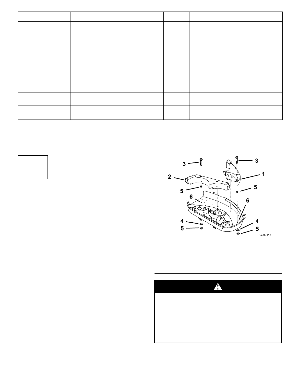
2.Removethelocknutsandwashersfromtheleftand
rightsidebafes(Figure3).Liftthebafesfromthe
deck.Retainallpartsforfutureinstallation.
1.Bafeleftside4.Curvedwasher-concave
2.Baferightside5.Locknut(5/16inch)
3.Bolt(5/16x1-1/4inches)6.Slottedhole
Figure3
sidetowarddecksurface
Openholesinthemowerexposeyouandothers
tothrowndebriswhichcouldcauseinjury.
•Neveroperatethemowerwithouthardware
mountedinallholesinthemower.
•Installhardwareinmountingholeswhen
anybafeisremoved.
Note:Loosehardwareisfurnishedwiththemower
deckassembly.
6
Page 7
2
InstallingtheHi-liftBlades
Partsneededforthisprocedure:
3
Hi-liftblades
Procedure
Installthehi-liftbladesfromthebaggerinplaceofthe
standardblades;refertotheCuttingBladesectionofthe
machineOperator’sManual.
Note:Thehi-liftbladesarealsousedformowerswith
Recycler®bafes.
3
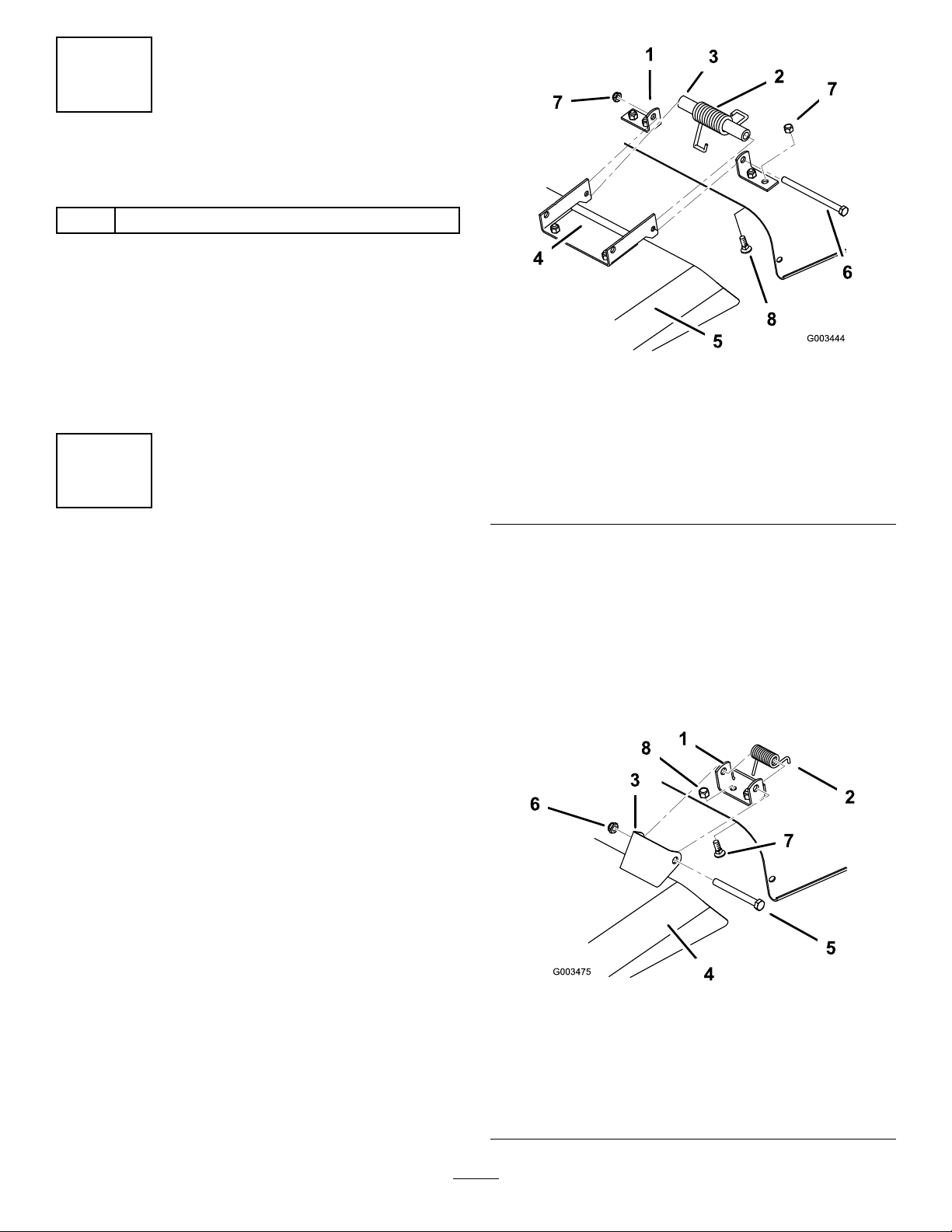
Figure4
1.Mountbracket,discharge
chute
2.Spring,hookedendsdown
3.Spacer8.Carriagebolt(5/16x5/8
4.Dischargechute,bracket
5.Dischargechute
6.Bolt
7.Locknut
inch)
9.Locknut(5/16inch)
RemovingtheDischarge
Chute
NoPartsRequired
Procedure
RubberDeectors
1.Removetheboltandnutsecuringthedischarge
chutetothemowerdeck(Figure4).Removethe
dischargechuteandspringassembly.Retainallparts
forfutureinstallation.
2.Removethecarriageboltsandlocknutssecuringthe
mountingbracketstothemower(Figure4).Remove
themountingbracket.
MetalDeectors
1.Removetheboltsandnutssecuringthedischarge
chutetothemowerdeck(Figure5).Removethe
dischargechuteandspringassemblies.Retainall
partsforfutureinstallation.
1.Mountbracket,discharge
chute
2.Spring,hookedendsdown
3.Dischargechute,bracket
4.Dischargechute
7
Figure5
5.Bolt
6.Locknut
7.Carriagebolt(5/16x5/8
inch)
8.Locknut(5/16inch)
Page 8
2.Removethecarriageboltsandlocknutssecuringthe
mountingbracketstothemower(Figure5).Remove
themountingbrackets.
Retainallpartsforfutureinstallation.
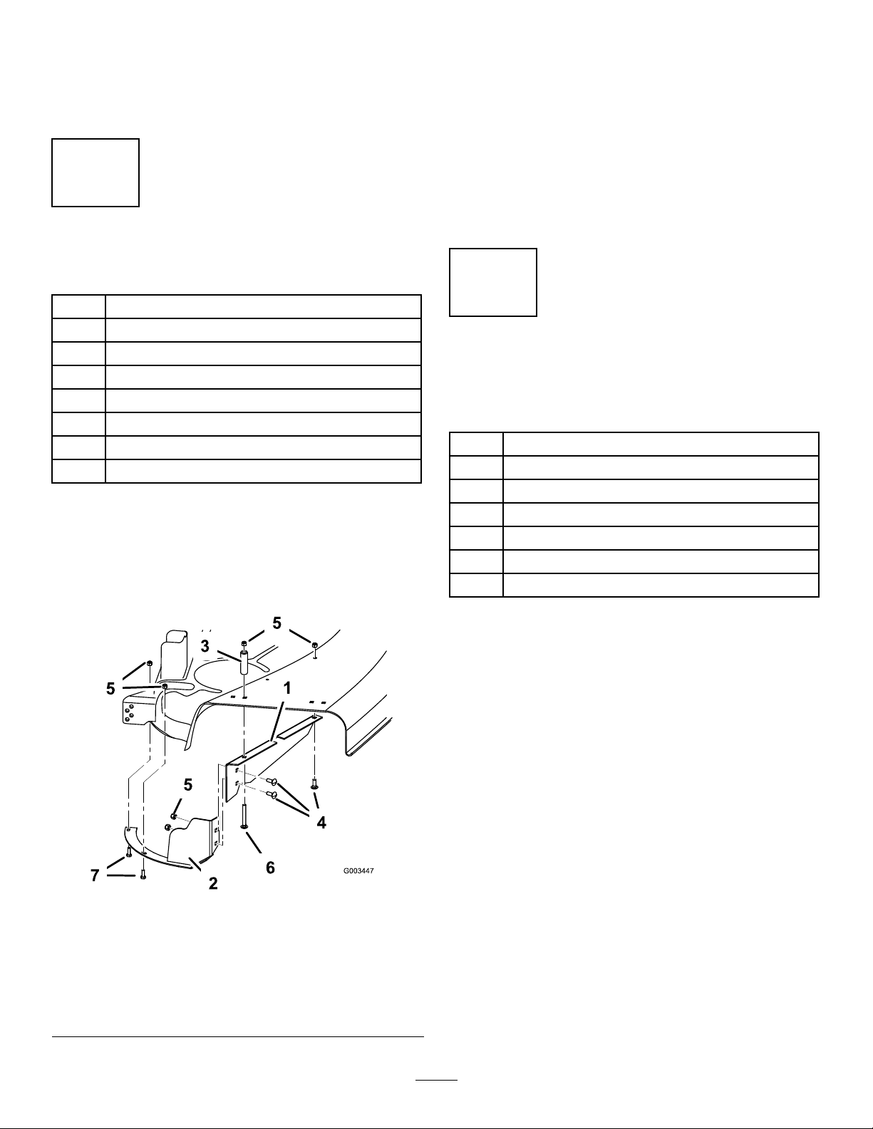
4
InstallingtheGrassBafe
Partsneededforthisprocedure:
2.Installthereargrassbafeandgrassringinsidethe
dischargechutearea.Securethereargrassbafeto
themowerwithashortcarriagebolt(5/16x7/8
inch)andalongcarriagebolt(5/16x2-1/2inch).
Addthelatchtubeabovethedeckandsecureitwith
twolocknuts(5/16inch).Securethegrassringto
themowerwithtwobolts(1/4x3/4inch)andtwo
locknuts(1/4inch)(Figure6).
3.Rotatethebladestomakesurethattheydonothit
thebafesorgrassring.Adjustthebafesasneeded.
1
Reargrassbafe
1
Grassring
3
Carriagebolt,(5/16x7/8inch)
4
Locknut,(5/16inch)
1
Carriagebolt,(5/16x2-1/2inch)
1
Spacer
2
Bolt(1/4x3/4inch)
2
Locknut(1/4inch)
Procedure
1.Attachthereargrassbafetothegrassringwithtwo
carriagebolts(5/16x7/8inch)andtwolocknuts
(5/16inch)(Figure6).
5
InstallingtheBlowerPivot
Support
Partsneededforthisprocedure:
1Pivotsupport
1Pivotbracket
1
Carriagebolt,(5/16x7/8inch)
1
Carriagebolt,(5/16x4-1/2inch)
1
Spacertube
4
Locknut(5/16inch)
2
Washer(11/32inch)
Procedure
1.Locatethepivotsupportonthemoweroverthe
squareholesnearthedischargeopening(Figure7).
Figure6
1.Reargrassbafe5.Locknut(5/16inch)
2.Grassring6.Carriagebolt(5/16x2-1/2
3.Latchtube
4.Carriagebolt(5/16x7/8
inch)
inch)
7.Screw(1/4x3/4inch)
8.Locknut(1/4inch)
8
Page 9
1.Pivotsupport
2.Carriagebolt(5/16x4-1/2
inch)
3.Spacertube
4.Carriagebolt(5/16x7/8
inch)
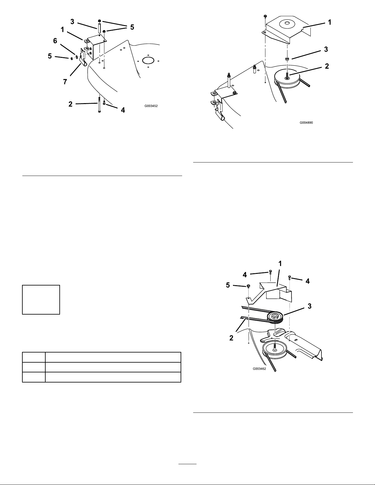
Figure7
5.Locknut(5/16inch)
6.Washer(5/16inch)
7.Pivotbracket
Figure8
1.Beltcover
2.Spindleshaft
3.Spindlepulleynut
Note:Saveallpartsandhardware.
2.Pushtheverticalside(front)ofthepivotsupport
againstthefrontofthemowerandclampitsnugly,
makingsurethetopofthepivotsupportliesaton
thetopofthemower.
3.Securethepivotsupporttothetopofthemower
withabolt(5/16x4-1/2inch),spacertube,andbolt
(5/16x7/8inch)(fromtheundersideofthemower)
andtwolocknuts(5/16inch)(Figure7).
4.Securethepivotbrackettothepivotsupportwith
twowashers(11/32inch)andtwolocknuts(5/16
inch)(Figure7).
6
InstallingtheBlowerPulley
Partsneededforthisprocedure:
1Beltcover
1Blowerpulley
1
Screw(1/4x1/2inch)
Procedure
1.Removethemowerbeltcoverfromtherightside
pulley(Figure8).
2.Removethespindlepulleynut.Blockthebladewith
apieceofwoodorsomeotherdevicetostopitfrom
turningwhileyouremovethepulleynut.
3.Threadthenewblowerpulleyontothespindleshaft
inplaceofthepulleynut(Figure9).T orquethe
pulleyto50to75ft-lb(68to102N⋅m).
4.Placetheblowerbeltaroundtheblowerpulley
(Figure9).
Figure9
1.Beltcover
2.Blowerbelt
3.Blowerpulley
4.Screw(existing)
5.Screw(1/4x1/2inch)
5.Installthebeltcoverusingtheexistingscrewsanda
newscrew(1/4x1/2inch)(Figure9).
9
Page 10

7
InstallingtheBlower
Partsneededforthisprocedure:
1Blowerassembly
1Belt
Procedure
1.Installthemowertothemachine;refertoOperator’ s
Manual.
2.Installtheblowerbyloweringthepivotpinintothe
pivotsupport(Figure10).
Figure11
1.Idlerpulleybracketand
pulley
2.Top(wide)sideofbelt
againstbottompulley
4.Withthebeltinstalled,swingtheblowertowardthe
moweruntiltheblowerlatchlocksoverthepinat
thebackofthemower(Figure12).
3.V-sideofbeltintotop
pulley
Figure10
1.Pivotpin2.Pivotsupport
3.Openthelatchandswingthebloweroutawayfrom
themower,installtheblowerbeltaroundtheidler
andblowerpulleysasshownFigure11.Installthe
otherendofthebeltovertheblowerdrivepulleyon
themowerspindle.
Important:Y oumayhavetolifttheblower
slightlyforthelatchtoclose.Ensurethatthe
latchoperates
1.Blowerlatch2.Pin
smoothl y
Figure12
andcloses
completel y
.
10
Page 11

8
InstallingtheBeltCovers
Partsneededforthisprocedure:
1Blowerbeltcover
2Handknob
4Washer
2
Locknut(5/16inch)(ForCEunitsonly)
Figure14.Usethesamelevelingholesforthenew
brackettokeepthemowerdecklevel.Secureitwith
theexistingwashersandhairpincotters.
Note:Savetheslottedlevelingbracketforfuture
sidedischargeoperation.
Procedure
Installtheblowerbeltcoverusingfourwashersandtwo
handknobs(Figure13).
Note:Forallinternationalmodels,usetwolocknuts
(5/16inch)tosecurethebeltcoverinsteadofhand
knobs..
Figure13
1.Mowerbeltcover
2.Washer
3.Handknob(Domestic
units)
Figure14
1.Holelevelingbracket2.Washerandhairpincotter
2.Checkthemowerlevelfront-to-rearandside-to-side;
refertotheOperator’ sManualforinstructions.
10
AssemblingtheBagger
Partsneededforthisprocedure:
1
Cover
1Indicatorrod
1Handle
1
Nut(1/4inch)
2
Clips
2
Bolt(1/4x3/4inch)
4
Locknut(1/4inch)
1Frameassembly
9
InstallingtheLevelingBracket
Partsneededforthisprocedure:
1Levelingbracket
Procedure
1.Replacetheleftsidemowerlevelingbracket(slotted)
withanewlevelingbracket(hole)asshownin
Procedure
1.Installthefull-bagindicatorrodthroughthehole
intherubbersealandtheslotinthebaggercover
(Figure15).Mountthefull-bagindicatorrodagainst
thebaggercoverusingtwoclips,screws(1/4x3/4
inch),andlocknuts(1/4inch)(Figure15).
2.Screwthenutcompletelyontotheindicatorrod
(Figure15).Thenscrewthehandle(Figure15)
closetothenutsoyoucanreadthedecalfromthe
operator’sposition.Tightenthenutupagainstthe
handletolockitinplace.
11
Page 12

11
InstallingtheWeight
Partsneededforthisprocedure:
1Weight
4
Bolt(3/8x1-1/2inches)
Figure15
1.Indicatorrod
2.Clips
3.Screw(1/4x3/4inch)
4.Locknut(1/4inch).
5.Nut
6.Handle
3.Attachtheframeassemblytothebaggercoverwith
twobolts(1/4x3/4inch)andtwolocknuts(1/4
inch)(Figure16).
Figure16
1.Frameassembly
2.Baggercover
3.Bolt,1/4x3/4inch
4.Locknut(1/4inch)
Procedure
Thebaggeraddsalotofweighttotherear
ofthemachineandmaycauseanunstable
conditionwhichcouldresultinalossofcontrol.
Installthefrontweight.
Attachtheweighttothefrontofthetractorwithfour
screws(3/8x1-1/2inches)Figure17.
Figure17
1.Frontweight
2.Screw(3/8x1-1/2inches)
12
Page 13

12
InstallingtheExhaust
Deector(forKawasaki
enginesonly)
Partsneededforthisprocedure:
1
Deector
1
Selftappingscrew
1.Insertthesolidtabintotheopeningaroundthe
exhaustpipefacingupwardstoensureallheatis
deectedawayfromtheattachmentandmachine.
2.Insertaselftappingscrewthroughtheholedtabat
thebottomofthedeectorandfastentotheguard
justbelowtheexhaustopeningintheguard.
Important:Makesurethatdeectorisseated
ushagainstthesurfaceoftheguardtoensure
allexhaustisdirectedawayfromthemachine.
13
Procedure
Exhaustmanifoldsandtheguardsaround
themcanretainheatwellaftertheengine
hasbeenstopped.Thesehotsurfacescan
causesevereburnsandcanignitecombustible
materialscausingseverepersonalinjurytoyou
orbystanders.
Allowtheexhaustmanifoldsandtheguards
aroundthemtheappropriateamounttimeto
coolbeforeperforminganymaintenance.
Installthedeectortothemuferguardasshownin
Figure18.
InstallingtheBaggerSupport
Assembly
Partsneededforthisprocedure:
1
Supportrod
2
Gusset
4
Spacer
4
Bolt(5/16x2inches)
4
Bolt(1/4x1-3/4inch)
12
Washer(9/32inch)
8
Locknut(1/4inch)
1
Quickattachbracket
1Hairpincotter
2Baggerplate
4
Bolt(1/4x1inch)
Procedure
Figure18
1.Guard,mufer3.Deector,directed
outwardsandawayfrom
themachine
2.Opening,exhaust4.Selftappingscrew
1.Removethebolts,washers,andnutsholdingtherear
supportrodtothetractor.Discardthebolts.Reuse
thenutandwashers.
2.Attachthesupportrodandgussetstothetractor
withfourbolts(5/16x2inches)andfourspacers
andthewashersandlocknutsremovedinthe
previousstep(Figure19).
13
Page 14

Figure19
1.Supportrod8.Quick-attachbracket
2.Gusset
3.Bolt(5/16x2inches)
4.Spacer11.Bolt(1/4x3/4inch)
5.Bolt(1/4x1-3/4inch)12.Locknut(1/4inch)
6.Washer(1/4inch)
7.Locknut(1/4inch)
9.Hairpincotter
10.Baggerplate
13.Existinghardware
14
InstallingtheBagger
Assembly
Partsneededforthisprocedure:
1Baggertop
2
GrassBag
Procedure
1.Carefullyliftthebaggertopandslideitontothe
quickattachbracket(Figure20).Thebaggertopis
easiertoinstalliftwopeopleworktogether.
3.Securetheupperhalfofthegussettotherear
supportrodwithfourbolts(1/4x1-3/4inch),eight
washers(1/4inch),andfourlocknuts(1/4inch)
(Figure19).
4.Slidethebottomofthequick-attachbracketdown
intotheholeinthehitchandhookthenotchesover
therearsupportrod(Figure19)
5.Slidethehairpincotterthroughtheholeatthe
bottomofthequick-attachbracket(Figure19)
6.Attachthebaggerplatestothequick-attachbracket
usingfourbolts(1/4x1-3/4inch),fourwashers
(1/4inch),andfourlocknuts(1/4inch)(Figure19)
Figure20
1.Baggertop
Ifyouremovethespring-loadedbaggertop
whenitisclosed(inthedownposition),thetop
maysuddenlyyopenandyouorsomeoneelse
maybebruised,pinched,orinjuredinanother
way.
Alwaysopen(raise)thebaggertopbeforeyou
removeorinstallitonthequick-attachbracket.
2.Installthebagsbyslidingthebagframehooksonto
theretainingbrackets(Figure21).
2.Quickattachbracket
14
Page 15

Figure21
1.Bagframehook
3.Lowerthebaggertopontothebags.Thenpush
downonbothbagretainerhandlesuntiltheylockon
thebagframe(Figure22).
2.Retainingbracket
15
MountingtheDischargeTube
Partsneededforthisprocedure:
1Dischargechute
Procedure
1.Inserttheupperendofthedischargetubeintothe
baggertop.Slidethelowerendofthedischarge
tubeintotheblowerdischargeextensionopening
(Figure23).
2.Hooktherubberlatchontotheknob(Figure23).
Figure22
1.Baggertop2.Bagretainerhandles
Figure23
1.Blowerdischarge
extension
2.Dischargetube4.Knob
3.Rubberlatch
15
Page 16

Operation
Note:Determinetheleftandrightsidesofthe
machinefromthenormaloperatingposition.
Toavoidpersonalinjury,followthese
procedures:
•Becomefamiliarwithalloperatingand
safetyinstructionsinthe
forthemowerbeforeusingthisattachment.
•Neverremovethedischargetube,bags,
baggertop,orthechutewhiletheengineis
running.
•Alwaysshuttheengineoffandwaitforall
movingpartstostopbeforeclearingan
obstructionfromthebaggingsystem.
•Neverdomaintenanceorrepairswhilethe
engineisrunning.
Operator’ s Man ual
1.Stopthemower,settheparkingbrake,and
disengagethebladecontrolswitch(PTO).Stopthe
engineandremovetheignitionkey.
2.Pulluponbothbagretainerhandlesuntilthey
unlockfromthebagframe(Figure25).Open(raise)
thebaggertop.
Figure25
1.Baggertop2.Bagretainerhandles
UsingtheFullBagTester
Asgrassiscutandblownintothebags,theleftbaglls
rst,thentherightbag.Ifyouoverllthebags,grass
willeventuallyplugthedischargetubeorelbow .
1.Stopthemachineandapplythebrake.
2.Tocheckifbothbagsarefull,periodicallyraise
thefullbagtesterhandle(Figure24).Ifyoufeel
resistanceasyouraisethehandle,thebagsmustbe
emptiedbecausetheyarefull(Figure24).
Figure24
1.Fullbagtesterhandle
2.Bagfull
3.Compressdebrisintothebags.Withbothhands,
liftuponthebagandunhookitfromtheretaining
bracket.Emptythebag.Repeattheprocedurefor
theotherbag.
4.Installthebagsbyslidingthebagframehooksonto
theretainingbrackets(Figure26).
Figure26
1.Bagframehook
2.Retainingbracket
EmptyingtheGrassBags
Becarefulwhenliftingorhandlingagrassbagthatis
full.Toemptythegrassbags:
5.Lowerthebaggertopontothebags.Thenpush
downonbothbagretainerhandlesuntiltheylock
onthebagframe.
16
Page 17

ClearingObstructionsfrom
theBagger
1.Stopthemower,shiftintoneutral,settheparking
brake,disengagethebladecontrolswitch,stopthe
engine,andremovetheignitionkey.Waitforall
movingpartstostop.
2.Checkthegrassbagsandemptythemiftheyarefull.
3.Removeandseparatethedischargetubeandchute
fromthebaggertopandmower.Usingastick
orsimilarobject,carefullyremoveandclearthe
obstructionfromthemower,dischargetube,chute,
andthebaggertop.
4.Afteryouremovetheobstruction,installthe
completebaggersystemandresumeoperation.
RemovingtheVac-Bagger
Anuncovereddischargeopeningcouldallow
thelawnmowertothrowobjectsintheoperator
orbystander’sdirectionandresultinserious
injury.Also,contactwiththebladecouldoccur.
Figure27
1.Blowerdischarge
extension
2.Dischargetube4.Knob
3.Rubberlatch
RemovingtheBagger
1.Raisethebaggertopandremovethegrassbags
fromthebagframe(Figure28).
Neveroperatethelawnmowerunlessyouinstall
acoverplate,amulchplate,oragrasschute
andcatcher.
RemovingtheDischargeTube
1.Unhooktherubberlatchontotheknob(Figure27).
2.Slidethelowerendofthedischargetubeoutofthe
blowerdischargeextensionopening(Figure27).
Pulltheupperendofthedischargetubeoutofthe
baggertop.
Figure28
1.Baggertop2.Bagretainerhandles
Ifyouremovethespring-loadedbaggertop
whenitisclosed(inthedownposition),thetop
maysuddenlyyopenandyouorsomeoneelse
maybebruised,pinched,orinjuredinanother
way.
Alwaysopen(raise)thebaggertopbeforeyou
removeorinstallitonthequick-attachbracket.
2.Carefullyliftthebaggertopandslideitoffthequick
attachbracket(Figure29).Thebaggertopiseasier
toremoveiftwopeopleworktogether.
17
Page 18

1.Baggertop
RemovingtheBeltCovers
Removethetwohandknobsandfourwasherssecuring
theblowerbeltcover(Figure31).Retainallpartsfor
futureinstallation.
Figure31
1.Mowerbeltcover3.Handknob
2.Washer
Figure29
2.Quickattachbracket
RemovingtheBlowerfromtheMower
3.Removetheplatesandfastenersfromthe
quick-attachbracket(Figure30).
Figure30
1.Quick-attachbracket
2.Plate
3.Hairpincotter
1.Openthelatchandswingtheblowerout,away
fromthemower.Removetheblowerbeltfromthe
idlerandblowerpulleys(Figure32).
Figure32
1.Idlerpulleybracketand
pulley
2.Top(wide)sideofbelt
againstbottompulley
3.V-sideofbeltintotop
pulley
2.Removetheblowerbyliftingthepivotpinoutof
thepivotsupport(Figure33).
4.Removethehairpincotterfromtheholeatthe
bottomofthequick-attachbracket(Figure30).
5.Slidethebottomofthequick-attachbracketupout
oftheholeinthehitch(Figure30).
18
Page 19

Figure33
1.Pivotpin2.Pivotsupport
RemovingtheBlowerPulleyfromthe
Mower
Figure35
1.Beltcover
2.Spindleshaft
RemovingtheBlowerPivotSupport
3.Spindlepulleynut
1.Removethemowerbeltcoverfromtherightside
pulley(Figure34).Savethemountinghardware.
2.Unhooktheblowerbeltfromtheblowerpulley
(Figure34).Removetheblowerbeltpulley.
Figure34
1.Beltcover
2.Blowerbelt
3.Blowerpulley
4.Screw(existing)
5.Screw(1/4x1/2inch)
3.Installthespindlepulleynutoverthespindleand
torqueto50to75ft-lb(68to102N⋅m)(Figure35).
1.Removethemowerfromthetractor;refertothe
tractorOperator’sManualforinstructions.
2.Removethepivotsupportandpivotbracketfrom
themower(Figure36).Retainallpartsforfuture
installation.
Figure36
1.Pivotsupport
2.Carriagebolt(5/16x4-1/2
inch)
3.Spacertube
4.Carriagebolt(5/16x7/8
inch)
5.Locknut(5/16inch)
6.Washer(5/16inch)
7.Pivotbracket
4.Installtheoldbeltcoverusingtheexistinghardware
(Figure35).
InstallingtheStandard-liftBlades
Installthestandard-liftbladesforsidedischargingin
placeofthehi-liftblades;refertotheCuttingBlade
sectionintheOperator’sManual.
19
Page 20

Note:Thehi-liftbladesareusedwiththeRecycler®
bafes.
RemovingtheGrassBafes
Openholesinthemowerexposeyouandothers
tothrowndebriswhichcouldcauseinjury.
•Neveroperatethemowerwithouthardware
mountedinallholesinthemower.
•Installhardwareinmountingholeswhen
theanybafeisremoved.
Removethereargrassbafeandgrassringfromthe
insideofthedischargechutearea(Figure37).Retainall
partsforfutureinstallation.
InstalltheDischargeChute
Withoutthegrassdeector,dischargecover,
orcompletegrasscatcherassemblymounted
inplace,youandothersareexposedtoblade
contactandthrowndebris.Contactwiththe
rotatingmowerblade(s)andthrowndebriswill
causeinjuryordeath.
•Neverremovethegrassdeectorfrom
themowerbecausethegrassdeector
routesmaterialdowntowardtheturf.Ifthe
grassdeectoriseverdamaged,replaceit
immediately.
•Neverputyourhandsorfeetunderthe
mower.
•Nevertrytoclearthedischargeareaor
mowerbladesunlessyoumovetheblade
controlswitch(PTO)toOffandrotatethe
ignitionkeytoOff.Alsoremovethekeyand
pullthewireoffofthesparkplug(s).
Figure37
1.Reargrassbafe5.Locknut(5/16inch)
2.Grassring6.Carriagebolt(5/16x2-1/2
3.Latchtube
4.Carriagebolt(5/16x7/8
inch)
inch)
7.Screw(1/4x3/4inch)
8.Locknut(1/4inch)
Note:Installhardwaretolltheholesinthemower.
InstallingtheRecycler®Bafes
RubberDeectors
1.Installthemountingbracketsontothemowerwith
carriagebolts(5/16x5/8inch)andlocknuts(5/16
inch)asshowninFigure38.
2.Installthedischargechuteontothemower
(Figure38)inbetweenthemountingbrackets.
IfyouwanttousetheRecycler®bafesinthemower
deck,youmustinstallthethosebafes;refertothe
InstallationInstructionsinyourRecycler®Kit.
20
Page 21

Figure38
1.Mountbracket,discharge
chute
2.Spring,hookedendsdown
3.Spacer8.Carriagebolt(5/16x5/8
4.Dischargechute,bracket
5.Dischargechute
6.Bolt
7.Locknut
inch)
9.Locknut(5/16inch)
3.Alignthedischargechutewiththeholesinthe
bracketsandthespringandspacerinthespace
betweenthebracketsandabovethedeector
(Figure38).
4.Placethespringandspacersothatthehooked
endsofthespringarepointingdown,withoneend
contactingonthemowerdeckandtheotherover
thedeector(Figure38).
5.Securethedeectortothemowerbracketwith
thebolt.Theboltshouldpassthroughthegrass
deector,spring,spacer,andbrackets.Securethe
assemblywiththelocknut(Figure38).
Note:Itmaybehelpfultopressdownnearthe
endoftheboltwitha9/16inchopenendwrench
toaligntheboltwiththesecondholeonthemower
bracketandgrassdeector.
6.Liftthedischargechuteandcheckthatitisspring
loadedandpivotsfreelytothefulldownposition.
Important:Thedischargechutemustbe
springloadedinthedownposition.Liftthe
deectoruptotestthatitsnapstothefulldown
position.
MetalDeectors
1.Installthemountingbracketsontothemowerwith
carriagebolts(5/16x5/8inch)andlocknuts(5/16
inch)asshowninFigure39.
2.Alignthedischargechutebracketoverthesprings
andmowermountingbrackets(Figure39).
Figure39
1.Mountbracket,discharge
chute
2.Spring,hookedendsdown
3.Dischargechute,bracket
4.Dischargechute
5.Bolt
6.Locknut
7.Carriagebolt(5/16x5/8
inch)
8.Locknut(5/16inch)
3.Alignthedischargechutebracketswiththeholesin
thebracketsandthespringsinthespacebetween
thebracketsandabovethedeector(Figure39).
4.Placethespringssoendsofthespringsarepointing
down,withoneendcontactingonthemowerdeck
andtheotheroverthedeector(Figure39).
5.Securethedeectortothemowerbracketswith
thebolts.Theboltsshouldpassthroughthegrass
deectorbrackets,springs,andmountbrackets.
Securetheassemblywiththelocknuts(Figure39).
6.Liftthedischargechuteandcheckthatitisspring
loadedandpivotsfreelytothefulldownposition.
Important:Thedischargechutemustbe
springloadedinthedownposition.Liftthe
deectoruptotestthatitsnapstothefulldown
position.
MountingtheMower
1.Installthemowerontothemachine;referto
Operator’sManualforinstructions.
2.Replacetheleftsidemowerlevelingbracket(hole)
withtheslottedlevelingbracket(Figure40).Secure
itwiththeexistingwashersandhairpincotters.
21
Page 22

Note:Savethe(hole)levelingbracketforusewhen
theblowerisinstalled.
Figure40
1.Holelevelingbracket2.Washerandhairpincotter
BaggingSpeed
Mostoftenyouwillbagwiththemowerthrottlein
theFastpositionanddriveatanormalgroundspeed.
However,inextremelydryanddustygrass,youmay
wanttoslightlyreducethethrottlespeedandincrease
thegroundspeedofthemower.Thebaggingsystem
mayplugifyoudrivetoofastandtheenginespeed
getstooslow .Onhillsitmaybenecessarytoslowthe
mowergroundspeed.Thishelpsmaintaintheengine
speedandbaggingefciency.Mowdownhillwhenever
possible.
3.Checkthemowerlevelfront-to-rearand
side-to-side;refertotheOperator’sManualfor
instructions.
OperatingTips
TipsforBagging
Size
Rememberthatthemowerislongerandwiderwiththis
attachmentinstalled.Byturningtoosharplyinconned
placesyoumaydamagetheattachment.
Trimming
Alwaystrimwiththeleftsideofthemower.Donot
trimwiththerightsideofthemowerbecauseyoucould
damagethebagger’schuteanddischargetube.
CuttingHeight
Donotsetthemowercuttingheighttoolowbecause
longgrasssurroundingthemowercanpreventairfrom
gettingunderthemowerandenteringthebagging
system.Ifenoughairdoesn’tgetunderthemower,the
baggingsystemwillplug.
CuttingFrequency
Cutthegrassoften,especiallywhenitgrowsrapidly.
Youwillhavetocutyourgrasstwiceifitgetsexcessively
long.
Asthebaggerlls,extraweightisaddedto
thebackofthemachine.Ifyoustopandstart
suddenlyonhills,youmaylosesteeringcontrol
orthemachinemaytip.
•Donotstartorstopsuddenlywhengoing
uphillordownhill.Avoiduphillstarts.
•Ifyoudostopthemachinewhengoing
uphill,disengagethebladecontrolswitch.
Thenbackdownthehillusingaslowspeed.
•Donotchangespeedsorstoponslopes.
BaggingLongGrass
BaggingLongGrassExcessivelylonggrassisheavyand
maynotbepropelledcompletelyintothegrassbags.If
thishappens,thedischargetubeandchutemayplug.
Toavoidpluggingthebaggingsystem,mowthegrass
atahighheightofcut,thenlowerthemowertoyour
normalcuttingheightandrepeatthebaggingprocess.
BaggingWetGrass
Alwaystrytocutgrasswhenitisdrybecauseyour
lawnwillhaveaneatappearance.Ifyoumustcutwet
grass,usetheconventionalsidedischargefeatureofthe
mower.Severalhourslater,whentheclippingsaredry,
installthecompletebaggerattachmentandvacuumup
thegrassclippings.
SignsofPlugging
CuttingTechnique
Forbestlawnappearance,besuretoslightlyoverlap
themowerintothepreviouslycutarea.Thishelps
reducetheloadontheengineandreducesthechance
ofpluggingthechuteanddischargetube.
Asyouarebagging,asmallamountofgrassclippings
normallyblowoutthefrontofthemower.Anexcessive
amountofclippingsblowingoutindicatesthatthebags
arefullorthesystemisplugged.
22
Page 23

Maintenance
Note:Determinetheleftandrightsidesofthemachinefromthenormaloperatingposition.
RecommendedMaintenanceSchedule(s)
MaintenanceService
Interval
Aftertherst10hours
Beforeeachuseordaily
Beforestorage
Ifyouleavethekeyintheignitionswitch,someonecouldaccidentlystarttheengineandseriously
injureyouorotherbystanders.
Removethekeyfromtheignitionanddisconnectthewirefromthesparkplugbeforeyoudoany
maintenance.Setthewireasidesothatitdoesnotaccidentallycontactthesparkplug.
Debrisbuiltupintheenginecompartment,ifnotremoved,couldbeignitedbyahotengine.Arein
theenginecompartmentcanburnyouandothersandcandamageproperty.
•Beforeusingandwhiletheengineiscool,checkfordebrisintheenginecompartment.
MaintenanceProcedure
•Inspectthebagger
•Cleanthebagger
•Inspectthebagger
•Cleanthebagger
•Keepthemachinefreeofgrass,leaves,orotherdebrisbuild-up.
•Cleanupoilorfuelspillageandfuelsoakeddebris.
•Allowthemachinetocoolbeforestoring.
InspectingtheBagger
Attachment
ServiceInterval:Aftertherst10hours
Beforestorage
Inspectthebaggerattachmentaftertherst10hoursof
operation,andmonthlythereafter.
1.Checkthechute,dischargetube,andthebaggertop.
Replacethesepartsiftheyarecrackedorbroken.
2.Tightenallnuts,bolts,andscrews.
3.Inspectthegrassbagsfordeterioration.
Youorbystanderscouldbeseverelyinjuredby
yingdebrisorthrownobjectsthatmaypass
throughtorn,worn,ordeterioratedgrassbags.
•Frequentlycheckthegrassbagsforholes,
rips,wear,andotherdeterioration.
•Donotwashthegrassbags.
•Ifthebaghasdeteriorated,installnewgrass
bagssuppliedbythemanufacturerofthis
baggerattachment.
InspectingtheMowerBlades
Inspectthemowerbladesregularlyandwhenevera
bladestrikesaforeignobject.
23
Page 24

Ifthebladesarebadlywornordamaged,installnew
blades.RefertoyourmowerormowerOperator’ sManual
forcompleteblademaintenance.
Storage
StoringtheBaggerAttachment
CaringfortheGrassBags
Washingthegrassbagsisnotrecommended.
Topreventrapiddeteriorationofthebagmaterial,store
thebagswheretheywilldrycompletelyaftereachuse.
CleaningtheBagger
Attachment
ServiceInterval:Beforeeachuseordaily
Beforestorage
1.Aftereachuse,removeandwashtheinsideand
outsideofthebaggertop,dischargetube,chute,and
theundersideofthemower,usingwatersprayed
fromagardenhose.Useamildautomotivedetergent
toremovestubborndirt.
2.Makesureyouremovemattedgrassfromallparts.
3.Afterwashing,letallofthepartsdrythoroughly .Do
notwashthegrassbags.
1.Cleanthebaggerattachment;refertoCleaningthe
BaggerAttachment.
2.Inspectthebaggerattachmentfordamage;referto
InspectingtheBaggerAttachment.
3.Makesurethegrassbagsareemptyandthoroughly
dry.
4.Storethebaggerinaclean,dryplace,outofdirect
sunlight.Thisprotectstheplasticpartsandextends
thelifeofthebagger.Ifyoumuststorethebagger
outside,coveritwithaweatherproofcover.
24
Page 25

Notes:
25
Page 26

Notes:
26
Page 27

Notes:
27
Page 28

Consumer
TimeCutter
ZX
A Three-Year Full Warranty (Limited Warranty for Commercial Use)
The Toro Total Coverage Guarantee
Conditions and Products Covered
The Toro Company and its afliate, Toro Warranty Company,
pursuant to an agreement between them, jointly promise to
repair any Toro Product used for normal residential purposes*
if defective in materials or workmanship. The following time
periods apply from the date of purchase:
Products Warranty Period
All TimeCutter ZX Mowers
and Attachments
All Batteries 1 year full warranty
This warranty covers both the cost of parts and labor, and
transportation within a fteen mile radius of the servicing dealer.
This warranty applies to all consumer TimeCutter ZX Mowers
and their attachments.
* Normal residential purposes means use of the product on
the same lot as your home. Use at more than one location is
considered commercial use, and the commercial use warranty
would apply.
3 year full warranty
Limited Warranty for Commercial Use
Toro Consumer Products and attachments used for commercial,
institutional, or rental use are warranted against defects in
materials or workmanship for the following time periods from the
date of purchase:
Products Warranty Period
Air Cooled Gas Engines 90 day limited warranty
All other items 30 day limited warranty
Instructions for Obtaining Warranty Service
If you think that your Toro Product contains a defect in materials
or workmanship, follow this procedure:
1. Contact any Toro Authorized or Master Service Dealer
to arrange service at their dealership. To locate a dealer
convenient to you, refer to the Yellow Pages of your
telephone directory (look under “Lawn Mowers") or access
our website at www.Toro.com. U.S. Customers may also
call toll free: 866-216-6029 to use our 24-hour Toro dealer
locator system.
2. Bring the product and your proof of purchase (sales receipt)
to the Service Dealer.
If for any reason you are dissatised with the Service Dealer’s
analysis or with the assistance provided, contact us at:
Customer Care Department, Consumer Division
Toro Warranty Company
8111 Lyndale Avenue South
Bloomington, MN 55420-1196
Toll Free: 866-216-6029 (U.S. customers)
Toll Free: 866-216-6030 (Canada customers)
Owner Responsibilities
You must maintain your Toro Product by following the
maintenance procedures described in the Operator’s Manual .
Such routine maintenance, whether performed by a dealer or by
you, is at your expense.
Items and Conditions Not Covered
There is no other express warranty except for special emission
system coverage on some products. This express warranty does
not cover:
• Cost of regular maintenance service or parts, such as lters,
fuel, lubricants, tune-up parts, blade sharpening, brake and
clutch adjustments.
• Any product or part which has been altered or misused
or required replacement or repair due to normal wear,
accidents, or lack of proper maintenance.
• Repairs necessary due to improper fuel, contaminants in the
fuel system, or failure to properly prepare the fuel system
prior to any period of non-use over three months.
• Pickup and delivery charges for distances beyond a fteen
mile radius from an Authorized Toro Service Dealer.
General Conditions
All repairs covered by this warranty must be performed by an
Authorized Toro Service Dealer using Toro approved replacement
parts.
Repair by an Authorized Toro Service Dealer is your sole
remedy under this warranty.
Neither The Toro Company nor Toro Warranty Company
is liable for indirect, incidental or consequential
damages in connection with the use of the Toro Products
covered by this warranty, including any cost or expense
of providing substitute equipment or service during
reasonable periods of malfunction or non-use pending
completion of repairs under this warranty.
Some states do not allow exclusions of incidental or
consequential damages, or limitations on how long an
implied warranty lasts, so the above exclusions and
limitations may not apply to you.
This warranty gives you specic legal rights, and you
may also have other rights which vary from state to
state.
Countries Other than the United States or Canada
Customers who have purchased Toro products exported from the United States or Canada should contact their Toro Distributor
(Dealer) to obtain guarantee policies for your country, province, or state. If for any reason you are dissatised with your Distributor’s
service or have difculty obtaining guarantee information, contact the Toro importer. If all other remedies fail, you may contact us
at Toro Warranty Company.
374-0073 Rev B
 Loading...