

Toro 79155 Parts Catalogue

Form Number 3358-179 Rev A
48in and 52in Bagger
Titan Zero-Turn-Radius Riding Mower
Model No. 79155 - 270000001 and up.
Parts Catalog
Ordering Replacement Parts
To order replacement parts, please supply the part
number, the quantity, and the description of each part
desired.
Understanding Reference Numbers
Each Identified part in an illustration has a reference
number. The reference number for a part also
appears in the parts list, along with other information
about the part.
This catalog uses two special reference number
formats, one to indicate parts in a service assembly
and another to indicate the quantity of a given part in
an illustration.
Service Assembly Reference Numbers
Parts in service assemblies have reference numbers
in the form a:b. The a represents the reference
number of the entire service assembly and the b
represents a sequential number unique to each part
within the service assembly.
© The Toro Company - 2007
Register your product at www.Toro.com
All Rights Reserved
For example, a wheel assembly might be identified
by reference number 6, the tire by 6:1, the valve by
6:2, and the wheel by 6:3. When you order the
assembly identified by reference number 6, you
receive all parts identified by reference numbers 6:1,
6:2, and 6:3. However, you may also order any part
individually. Reference numbers of this type appear
in illustrations and in part lists.
Reference Numbers Indicating Quantity
In an illustration, if a reference number indicates
more than one part, the reference number has the
form nX y. The n represents the quantity of the part,
the X is the multiplication symbol, and the y
represents the reference number.
For example, in an illustration, the reference number
2X 37 means that two of the parts identified by
reference number 37 are indicated.

Contents
Description Page
. . . . . . 3Bagger Hood and Upper Tube Assembly
. . . . . . 4Hood Assembly No. 109-6796
. . . . . . 5Bagger Mount Assembly No. 109-6771
. . . . . . 6Baffle and Boot Mount Assembly
Description Page
Part Description Abbreviations
Part descriptions in this catalog may include the following abbreviations.
AR. . . . . . . . . . . . . . .as required
ASM. . . . . . . . . . . . . assembly
BBC. . . . . . . . . . . . . blade brake clutch
CARR. . . . . . . . . . . . carriage
DEG. . . . . . . . . . . . . degrees
EXT. . . . . . . . . . . . . .external
FH. . . . . . . . . . . . . . .flat head
GA. . . . . . . . . . . . . . .gauge
HD. . . . . . . . . . . . . . .heavy-duty
HF. . . . . . . . . . . . . . . hex flange
HH. . . . . . . . . . . . . . .hex head
HHF. . . . . . . . . . . . . hex head flange
HHFTF. . . . . . . . . . . hex head flange thread forming
HJ. . . . . . . . . . . . . . . hex jam
HLH. . . . . . . . . . . . . .hex lag head
HOC. . . . . . . . . . . . . height-of-cut
HSBH. . . . . . . . . . . . hex socket button head
HSFH. . . . . . . . . . . . hex socket flat head
HSH. . . . . . . . . . . . . hex socket head
HWH. . . . . . . . . . . . . hex washer head
HWHTF. . . . . . . . . . .hex washer head thread
forming
HYD. . . . . . . . . . . . . hydraulic
LH. . . . . . . . . . . . . . . left hand
NI. . . . . . . . . . . . . . . nylon insert
NPTF. . . . . . . . . . . . national pipe thread fine
PFH. . . . . . . . . . . . . .phillips flat head
PPH. . . . . . . . . . . . . phillips pan head
PPHTF. . . . . . . . . . . phillips pan head thread
PRH. . . . . . . . . . . . . phillips round head
PTH. . . . . . . . . . . . . .phillips truss head
PTO. . . . . . . . . . . . . power-take-off
RH. . . . . . . . . . . . . . .right hand
ROPS. . . . . . . . . . . . roll-over protection system
SFH. . . . . . . . . . . . . .slotted fillister head
SHH. . . . . . . . . . . . . slotted hex head
SHWH. . . . . . . . . . . .slotted hex washer head
SPH. . . . . . . . . . . . . slotted pan head
SQH. . . . . . . . . . . . . square head
SRH. . . . . . . . . . . . . slotted round head
STD. . . . . . . . . . . . . .standard
TAP. . . . . . . . . . . . . .self tapping
TTH. . . . . . . . . . . . . .torx truss head
. . . . . . 7Lower Tube Assembly No. 109-6769
. . . . . . 8Bag Frame Assembly
. . . . . . 9Bag Assembly No. 112-3994
. . . . . . 10Bagger Weight Assembly
forming
2
3358-179 Rev A
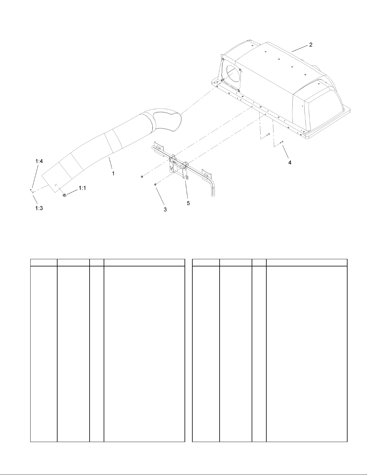
Bagger Hood and Upper Tube Assembly
Ref Part No. Qty. Description
Upper Tube ASM1
109-1939
103-4081
3290-500
3256-14
109-6796
104-7201
321-4
109-6771
1
Latch-Keeper1:1
2
Screw-PPH1:3
2
Washer-Flat1:4
2
Hood ASM2
1
Nut-HF3
2
Screw-HH4
2
Bagger Mount ASM5
1
3
3358-179 Rev A
A1
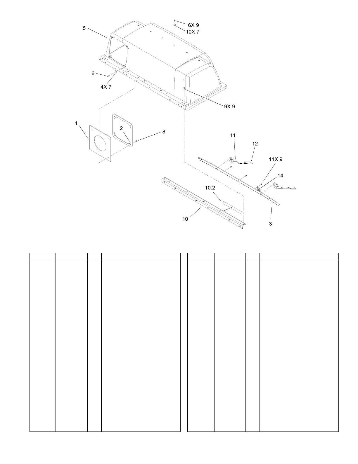
Hood Assembly No. 109-6796
Ref Part No. Qty. Description
Seal-Chute1
14
26
1
Clamp-Seal2
1
Support-Screen3
1
Top-Bagger5
1
Screw-PPH6
4
Washer-Flat7
Nut-Lock8
4
Rivet-Pop9
Stiffener And Decal10
1
Decal-Caution Bagger10:2
1
Latch-Bagger, Top11
2
Grip12
2
Screen-Bagger14
1
1-653561
1-653598-03
92-1736-03
105-9100
3250-27
3256-61
3296-2
114439
109-6861
109-6809
115481-03
115880
114967
4
 Loading...