

Page 1

FormNo.3363-517RevB
44inSideDischargeMower
2005andAfterXL440HLawnTractor
ModelNo.79110—SerialNo.310000001andUp
ToregisteryourproductordownloadanOperator'sManualorPartsCatalogatnocharge,gotowww.T oro.com.OriginalInstructions(EN)
Page 2
ThisproductcomplieswithallrelevantEuropean
directives.Fordetails,seetheseparateproductspecic
DeclarationofConformity(DOC)sheet.
Introduction
Figure2
1.Safetyalertsymbol
Thisequipmentisdesignedtobepartofariding
lawnmower,whichisintendedtobeusedby
residentialhomeowners.Itisdesignedprimarily
forcuttinggrassonwell-maintainedlawnson
residentialproperties.Itisnotdesignedforcutting
brushorforagriculturaluses.
Readthisinformationcarefullytolearnhowtooperate
andmaintainyourproductproperlyandtoavoidinjury
andproductdamage.Y ouareresponsibleforoperating
theproductproperlyandsafely.
YoumaycontactTorodirectlyatwww .Toro.comfor
productandaccessoryinformation,helpndinga
dealer,ortoregisteryourproduct.
Wheneveryouneedservice,genuineT oroparts,or
additionalinformation,contactanAuthorizedService
DealerorToroCustomerServiceandhavethemodel
andserialnumbersofyourproductready.
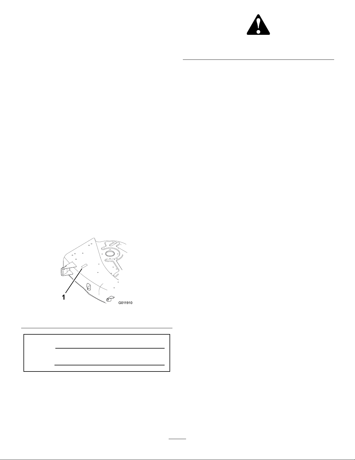
Figure1
identiesthelocationofthemodelandserialnumbers
ontheproduct.Writethenumbersinthespace
provided.
Figure1
1.Modelandserialnumberlocation
ModelNo.
SerialNo.
Thismanualuses2wordstohighlightinformation.
Importantcallsattentiontospecialmechanical
informationandNoteemphasizesgeneralinformation
worthyofspecialattention.
Contents
Introduction.................................................................2
Safety...........................................................................3
SafetyandInstructionalDecals.............................3
Setup............................................................................4
1PreparingtheMower.........................................5
2InstallingtheMower..........................................5
3LevelingtheMowerfromSideto
Side..................................................................7
4AdjustingtheFront-to-RearBlade
Slope................................................................8
5RemovingtheMower.......................................10
ProductOverview......................................................11
Specications.....................................................11
Operation...................................................................12
SideDischargingorMulchingGrass....................12
UsingtheBladeControl(PTO)...........................12
SettingtheHeight-of-Cut...................................12
TipsforMowingGrass.......................................12
Maintenance...............................................................14
RecommendedMaintenanceSchedule(s)................14
BladeMaintenance.................................................14
ServicingtheCuttingBlade.................................14
InspectingtheBlade(s).......................................14
RemovingtheBlade............................................14
SharpeningtheBlade(s)......................................15
InstallingtheBlade(s).........................................15
Cleaning.................................................................16
WashingtheUndersideoftheMower..................16
Storage.......................................................................17
Troubleshooting.........................................................18
Thismanualidentiespotentialhazardsandhas
safetymessagesidentiedbythesafetyalertsymbol
(
Figure2),whichsignalsahazardthatmaycauseserious
injuryordeathifyoudonotfollowtherecommended
precautions.
©2009—TheT oro®Company
8111LyndaleAvenueSouth
Bloomington,MN55420
Contactusatwww.T oro.com.
2
PrintedintheUSA
AllRightsReserved
Page 3
Safety
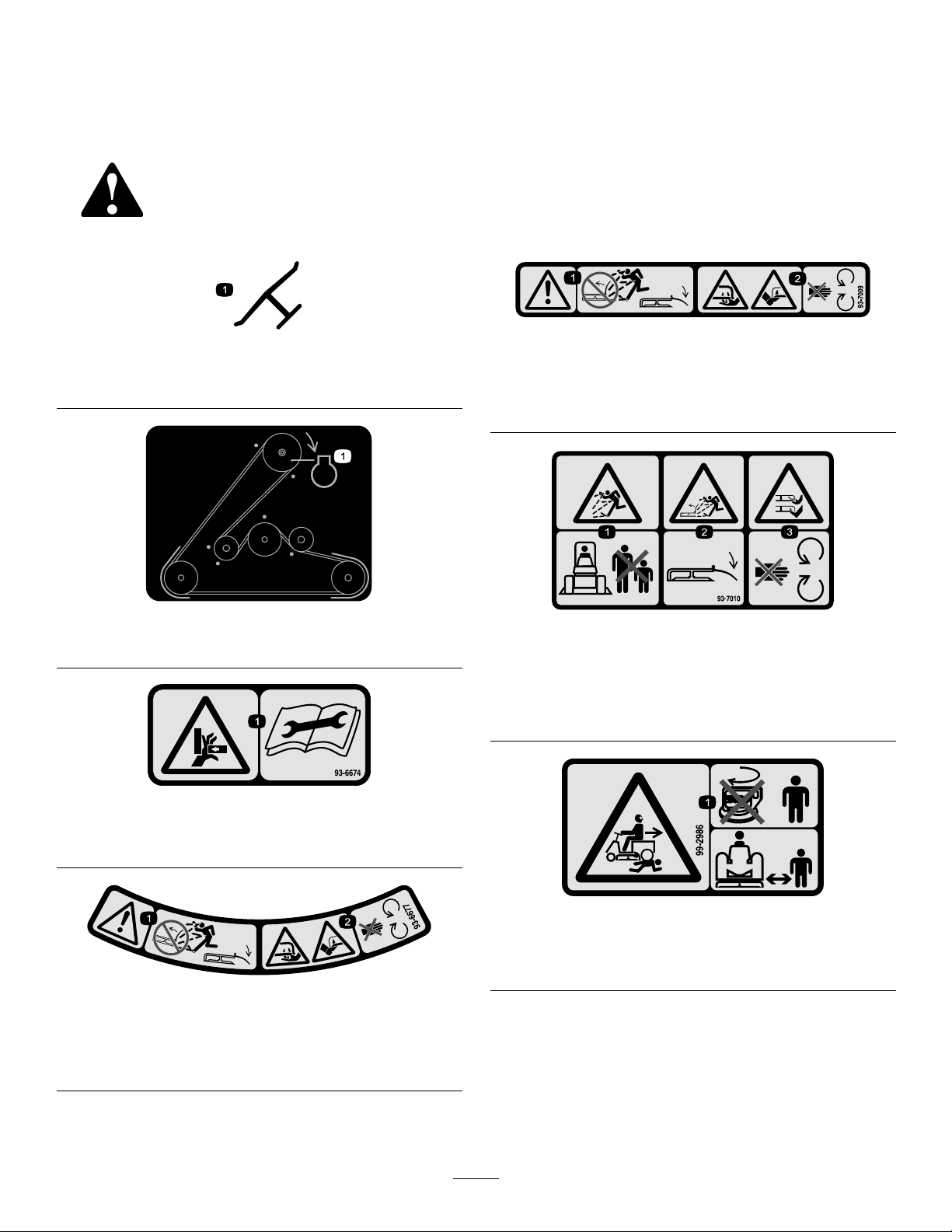
93-3777
SafetyandInstructionalDecals
Safetydecalsandinstructionsareeasilyvisibletotheoperatorandarelocatednearanyareaof
potentialdanger.Replaceanydecalthatisdamagedorlost.
Manufacturer’sMark
1.Indicatesthebladeisidentiedasapartfromtheoriginal
machinemanufacturer.
93-3777
1.Engine
93-7009
1.Warning—don’toperatethemowerwiththedeectorupor
removed;keepthedeectorinplace.
2.Cutting/dismembermenthazardofhandorfoot,mower
blade—stayawayfrommovingparts.
93-7010
1.Thrownobjecthazard—keepbystandersasafedistance
fromthemachine.
2.Thrownobjecthazard,mower—keepthedeectorinplace.
3.Cutting/dismembermentofhandorfoot—stayawayfrom
movingparts.
93-6674
1.Crushinghazard,hand—readtheinstructionsbefore
servicingorperformingmaintenance.
93-6677
1.Warning—don’toperatethemowerwiththedeectorupor
removed;keepthedeectorinplace.
2.Cutting/dismembermenthazardofhandorfoot,mower
blade—stayawayfrommovingparts.
99-2986
1.Crushing/dismembermenthazardofbystanders—donot
turnthekeywhilechildrenarepresent;keepchildrenasafe
distancefromthemachine.
3
Page 4

Setup
LooseParts
Usethechartbelowtoverifythatallpartshavebeenshipped.
ProcedureDescription
1
2
3
4
5
Grassdeector
Spring
Bolt,3/8x3-1/2in.
Locknut,3/8in.
Gagewheel
Pin2
Hairpincotter2
Mowermountingplate1
Shoulderbolt
Locknut2
Bolt,5/16x2-1/2in.
Locknut,5/16in.
Hairpincotter4
Thinwasher2
Thickwasher2
Nopartsrequired
Nopartsrequired
Nopartsrequired
Qty.
Use
1
2
2
2
2
2
2
2
–
–
–
Preparethemower.
Installthemower.
Levelthemowerfromsidetoside
Adjustthefront-to-rearbladeslope.
Removethemower.
4
Page 5
1
PreparingtheMower
Partsneededforthisprocedure:
1
Grassdeector
2
Spring
2
Bolt,3/8x3-1/2in.
2
Locknut,3/8in.
2
Gagewheel
2Pin
2Hairpincotter
1Mowermountingplate
2
Shoulderbolt
2Locknut
Procedure
Important:Thegrassdeectormustbespring
loadedinthedownposition.Liftthedeector
uptotestthatitsnapstothefulldownposition.
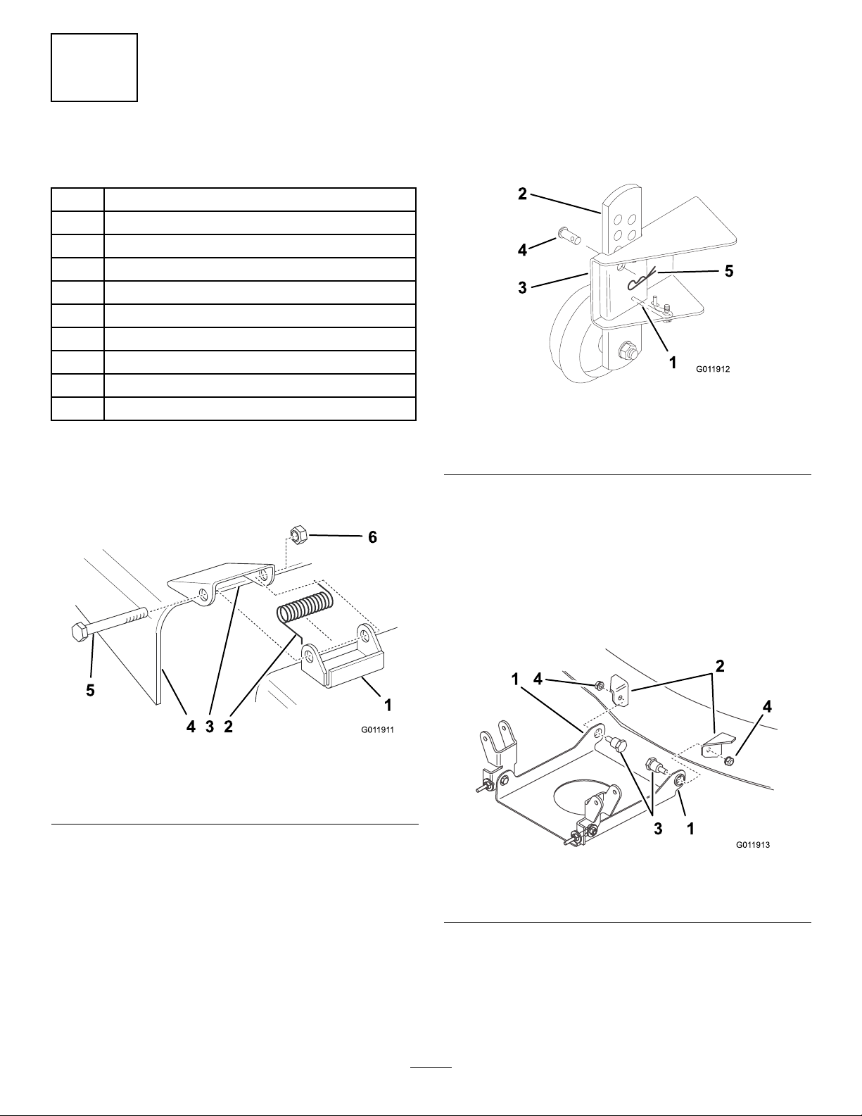
5.Deecttheanti-rattlespring,slidetheadjusting
plateofthegagewheelintothemowergagewheel
bracket,andsecureitwiththepinandhairpincotter
Figure4).
(
Figure4
1.Anti-rattlespring4.Pin
2.Plate5.Hairpincotter
3.Bracket
1.Placethespringsintothebracketsonthemower
withthehookedendsovertheraisedback(Figure3).
Figure3
1.Bracket
2.Springhookend
3.Spaceforspring
4.Grassdeector
5.Bolt
6.Locknut
2.Alignthegrassdeectorwiththeholesinthe
bracketsandthestraightendsofthespringinthe
spaceunderthehingeandabovethedeector
(
Figure3).
Note:Afterinstallingthemowerontothetractor,
settheheight-of-cutandadjustthegagewheels;
refertoSettingtheHeight-of-Cut(page12).
6.Repeattheadjustmentontheothergagewheels.
7.Positionthemountingplate,withthetabsup,
betweenthebracketsonthefrontofthemower
Figure5).
(
Figure5
1.Tabup
2.Mowerbracket4.Locknut
3.Shoulderbolt
3.Securethedeectortothebracketwithboltsthrough
thegrassdeector,springs,andbrackets.Secure
themwiththelocknuts(Figure3).
4.Liftthegrassdeectorandcheckthatitisspring
loadedandpivotsfreelytothefulldownposition.
8.Inserttheshoulderboltsthroughthemountingplate
intothemowerbrackets.Securethemwithlocknuts
(Figure5).
5
Page 6
2
InstallingtheMower
Partsneededforthisprocedure:
2
Bolt,5/16x2-1/2in.
2
Locknut,5/16in.
4Hairpincotter
2Thinwasher
2Thickwasher
Procedure
DANGER
Withoutthegrassdeector,dischargecover,or
completegrasscatcherassemblymountedinplace,
youandothersareexposedtobladecontactand
throwndebris.Contactwiththerotatingmower
blade(s)andthrowndebriswillcauseinjuryor
death.
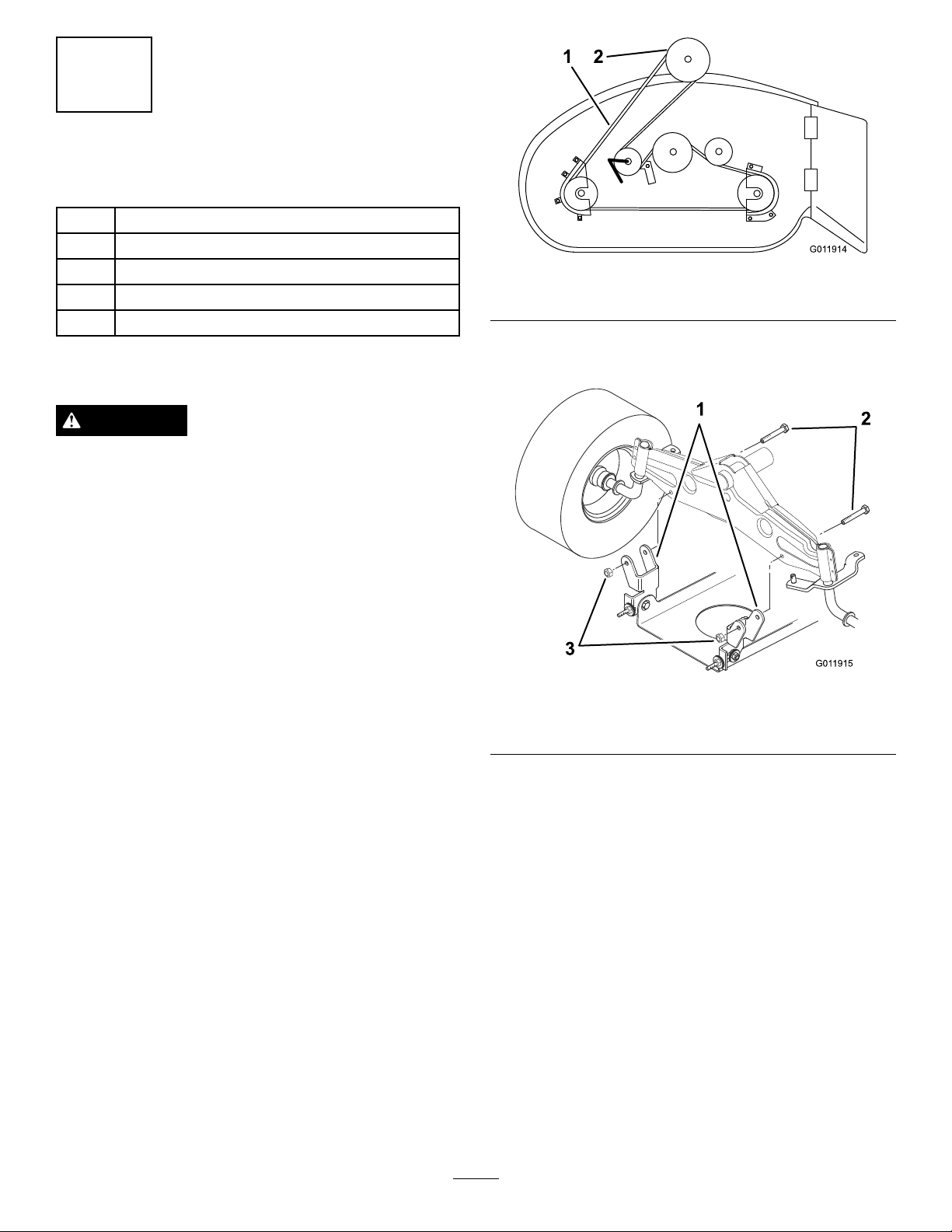
Figure6
1.Mowerbelt2.Electricclutchpulley
4.Installthemowerpivotmountbracketsontothe
frontaxlewiththeboltsandlocknuts(Figure7).
•Neverremovethegrassdeectorfromthemower
becausethegrassdeectorroutesmaterialdown
towardtheturf.Ifthegrassdeectorisever
damaged,replaceitimmediately.
•Neverputyourhandsorfeetunderthemower.
•Nevertrytoclearthedischargeareaormower
bladesunlessyoumovethepowertakeoff
(PTO)toOffandrotatetheignitionkeytoOff.
Alsoremovethekeyanddisconnectthewire
fromthesparkplug(s).
1.Parkthemachineonalevelsurface,disengagethe
bladecontrol(PTO),settheparkingbrake,andturn
theignitionkeytoOfftostoptheengine.Remove
thekey .
2.Turnthefrontwheelsfullytotheleft.Slidethe
mowerunderthechassisfromtherightside.
3.Installthemowerbeltontotheelectricclutchpulley
Figure6).
(
Figure7
1.Pivotmountbracket3.Locknut
2.Bolt,5/16x2-1/2in.
5.Movetheheight-of-cutleverintotheDnotch.
6.Removetheliftassistspringbetweenthemower
rightsideliftbracketandtheretainingbolt(Figure8).
6
Page 7

Figure8
1.Spring3.Springtool
2.Bolt
Note:Usethespringtoolprovidedwiththe
machine.
7.Movetheheight-of-cutleverintotheAnotch.
8.Ensurethatbothrodsextend5/8in.(16mm)
beyondtheadjustmentblock(Figure9).
14.Hookthespringfromtheidlerpulleyarmtothe
bracketonthemower(
1.Spring
2.Idlerpulleyarm
Figure10).
Figure10
3.Bracket
15.Movetheheight-of-cutleverintotheDnotchto
makeiteasiertoinstalltheheight-of-cutliftassist
spring.
16.Hooktheliftassistspringbetweenthemowerright
sideliftbracketandtheretainingbolt(Figure11).
Figure9
1.Rod4.Levelingbracket
2.Adjustingblock5.Mowermount
3.Hairpincotterandthick
washer
6.Hairpincotterandthin
washer
9.Slidetheendofthelongrodthroughtheholeinthe
mowermount(Figure9).
10.Installthethinwasherandhairpincottertosecure
therodinplace(Figure9).
11.Mounttheslottedmowerlevelingbracketontothe
pinonthemowermount(Figure9).
12.Installthethickwasherandhairpincottertosecure
themower(Figure9).
13.Repeatsteps9through12ontheoppositesideof
themower.
Figure11
1.Spring3.Springtool
2.Bolt
Note:Usethespringtoolprovidedwiththis
machine.
17.Checkthemowerlevel;referto
3LevelingtheMowerfromSidetoSide(page7)and
to4AdjustingtheFront-to-RearBladeSlope(page8).
7
Page 8

3
LevelingtheMowerfromSide
toSide
NoPartsRequired
Procedure
Themowerbladesmustbelevelfromsidetoside.
Checktheside-to-sidelevelanytimeyouinstallthe
mowerorwhenyouseeanunevencutonyourlawn.
Beforeyoulevelthemower,settheairpressureinthe
frontandreartires;refertothetractorOperator’sManual
forthecorrecttirepressure.
1.Parkthemachineonalevelsurface,disengagethe
PTO,settheparkingbrake,stoptheengine,and
removetheignitionkey.
2.Movetheheight-of-cutleverintothe“C”notch.
3.Carefullyrotatetheblade(s)sidetoside,andmeasure
betweentheoutsidecuttingedgesandtheat
surface(
Figure12).
Figure13
1.Hairpincotterandwasher3.Fronthole
2.Levelingbracket4.Rearhole
5.Toleveltheblade(s),repositionthelevelingbracket
inadifferentholeandinstallthewasherandhairpin
cotter.(
Note:Afrontholelowersthebladeheightanda
rearholeraisesitsheight.
6.Adjustbothsidesasrequired.
7.Checkthefront-to-rearbladeslope;referto
4AdjustingtheFront-to-RearBladeSlope(page8).
Figure13).
4
AdjustingtheFront-to-Rear
BladeSlope
Figure12
1.Bladessidetoside3.Measurehere
2.Outsidecuttingedges
Note:Ifbothmeasurementsarenotwithin3/16
in.(5mm),anadjustmentisrequired;refertosteps
4and5.
4.Removethehairpincotterandwasherfromthe
levelingbracket(
Figure13).
NoPartsRequired
Procedure
Checkthefront-to-rearbladeslopeanytimeyouinstall
themower.Beforeyouchecktheslope,settheair
pressureinthefrontandreartirestotherecommended
ination;refertothetractorOperator’sManualforthe
correcttirepressure.
1.Parkthemachineonalevelsurface.
2.Disengagethebladecontrol(PTO).
3.Settheparkingbrake.
4.TurntheignitionkeytoOff(tostoptheengine)and
removethekey.
5.Disconnectthewirefromthesparkplug.
6.Checkandadjusttheside-to-sidebladelevel
ifyouhavenotcheckedthesetting;referto
3LevelingtheMowerfromSidetoSide(page7).
8
Page 9

7.Measurethelengthoftherodextendingoutof
thefrontoftheadjustingblockonthesidesofthe
chassis(Figure14).
Figure14
1.Adjustingblock3.Hairpincotterandwasher
2.Longrod4.Mowermount
Note:Iftherodlengthisnot5/8in.(16mm),
removethehairpincotterandwasherfromtheend
oftherod(
Figure14)andturntheroduntilyou
obtainthe5/8inch(16mm)dimension.
Figure15
1.Bladefronttorear
2.Measurefrontbladetip
3.Measurerearbladetip
4.Measurehere
13.Ifthefrontbladetipisnotwithinarangeof0to
5/16inches(0to8mm)lowerthantherear,adjust
thefront-to-rearbladeslope(steps14through17);
otherwise,skiptostep
18.
14.Toadjustthefront-to-rearbladeslope,loosenthe
frontpivotplatemountingboltsslightly(Figure16).
8.Installtheendoftherodintotheholeinthemower
mountandsecureitwiththewasherandhairpin
cotter.
9.Repeatsteps7and8ontheoppositesideofthe
mower.
10.Movetheheight-of-cutleverintopositionC.
11.Carefullyrotatethebladessothattheyarefacing
fronttorear.
12.Checkthefront-to-rearslopebymeasuringbetween
thebottomofthemower(frontcenterandrear
center)andtheatsurface(
Figure15).
Figure16
1.Pivotmountingbolt2.Eyeboltlocknut
15.Rotatethelocknutsontheeyeboltstochangethe
adjustment(Figure16).Toraisethefrontofthe
mower,tightentheeyeboltlocknuts.Tolowerthe
frontofthemower,loosentheeyeboltlocknuts.
16.Afteradjustingbotheyeboltlocknutsevenly ,check
thefront-to-rearslopeagain.Continueadjustingthe
eyeboltsuntilthefrontbladetipis0to5/16in.(0to
8mm)lowerthantherearbladetip.
17.Whenthefront-to-rearslopeiscorrect,tightenthe
pivotplatemountingbolts(Figure16).
9
Page 10

18.Whenthefront-to-rearbladeslopeiscorrect,
checktheside-to-sidelevelofthemower;referto
3LevelingtheMowerfromSidetoSide(page7).
19.Checkthegagewheelheight;referto
SettingtheHeight-of-Cut(page12).
5
RemovingtheMower
NoPartsRequired
Procedure
1.Parkthemachineonalevelsurface.
2.DisengagethePTO.
3.Settheparkingbrake.
4.Stoptheengineandremovetheignitionkey.
5.Movetheheight-of-cutleverintotheDnotch.
6.Removetheliftassistspringbetweenthemowerright
sideliftbracketandtheretainingbolt(
Figure17).
Figure18
Viewfromtheleftside
1.Spring
2.Idlerpulleyarm
9.Removetheboltsandlocknutsandpullthetwo
mowerpivotmountbracketsdownfromthefront
axle(Figure19).
3.Bracket
Figure17
1.Spring3.Springtool
2.Bolt
Note:Usethespringtoolprovidedwiththe
machine.
7.Movetheheight-of-cutleverintotheAnotch.
8.Unhookthespringontheidlerpulleyarmfromthe
bracketonthemower(Figure18).
Figure19
1.Pivotmountbracket3.Locknut
2.Bolt(5/16x2-1/2in.)
10.Removethehairpincotterandwasherfromtheend
ofthelongrod(Figure20).Slidetherodoutofthe
mowermount.
10
Page 11

Figure20
1.Hairpincotterandwasher3.Levelingbracket
2.Longrod4.Mowermount
11.Removethehairpincotterandwasheratthemower
levelingbracket(
Figure20).Slidethebracketoffthe
mountingpin.Installthewasherandhairpincotter
forstorage.
12.Rotatethelevelingbracketuptowardtheframe,and
hookthelongrodintooneoftheholestostore.
Securethelongrodwiththewasherandhairpin
cotter.
ProductOverview
Specications
ModelWeightLengthWidthHeight
79110104lb
(47kg)
55in
(140cm)
(71cm)
28in
10in
(25cm)
13.Repeatsteps10through12ontheoppositesideof
themower.
14.Movetheheight-of-cutleverintotheDnotchand
hooktheliftassistspringontotheretainingboltfor
storage(
Figure17).
Note:Donotinstalltheliftassistspringiftherear
tirechainsaretobeinstalled.
15.Removethemowerbeltfromtheelectricclutch
pulley(Figure21).
Figure21
1.Mowerbelt2.Electricclutchpulley
16.Turnthefrontwheelsfullytotheleft.Slidethe
mowerouttotherighttocompleteremoval.
11
Page 12

Operation
Note:Determinetheleftandrightsidesofthe
machinefromthenormaloperatingposition.
SideDischargingorMulching
Grass
DANGER
Withoutthegrassdeector,dischargecover,or
completegrasscatcherassemblymountedin
place,youandothersareexposedtobladecontact
andthrowndebris.Contactwiththerotating
mowerblade(s)andthrowndebriswillcauseinjury
ordeath.
•Neverremovethegrassdeectorfromthe
mowerbecausethegrassdeectorroutes
materialdowntowardtheturf.Ifthe
grassdeectoriseverdamaged,replaceit
immediately.
•Neverputyourhandsorfeetunderthemower.
•Nevertrytoclearthedischargeareaormower
bladesunlessyoumovethepowertakeoff
(PTO)toOffandrotatetheignitionkeytoOff.
Alsoremovethekeyanddisconnectthewire
fromthesparkplug(s).
Themowerhasahingedgrassdeectorthatdisperses
clippingstothesideanddowntowardtheturf.T o
mulchgrassclippingsyoumustinstalltheRecycler®kit
(optionalonsomemodels).
Figure22
1.Height-of-cutlever
3.Adjusteachmowergagewheeltothecorrectheight,
asfollows:
A.Removethehairpincotterandpintochangethe
holelocation(
1.Wheel3.Hairpincotter
2.Pin
Figure23).
Figure23
UsingtheBladeControl(PTO)
Thebladecontrol(PTO)engagesanddisengagespower
totheblade(s).RefertoyourtractorOperator’sManual
foracompletedescriptionofthebladecontrol.
SettingtheHeight-of-Cut
Theheight-of-cutleverisusedtoraiseandlower
themowertothedesiredcuttingheight.Youcan
settheheight-of-cuttooneofsevenpositionsfrom
approximately1-1/2to4-1/2inches(38to116mm).
1.Parkthemachineonalevelsurface,disengagethe
PTO,settheparkingbrake,stoptheengine,and
removetheignitionkey.
2.Pullontheheight-of-cutleveronthetractorand
moveittothedesiredposition(
Figure22).
B.Selectaholepositionsothatthegagewheel
is3/8in.(10mm)offthegroundforthe
height-of-cuttobeused(
C.Insertthepinandsecureitwiththehairpin
cotter.
Figure23).
TipsforMowingGrass
FastThrottleSetting
Forbestmowingandmaximumaircirculation,operate
theengineatFast.Airisrequiredtothoroughlycut
grassclippings,sodonotsettheheightofcuttoolow
ortotallysurroundthemowerbyuncutgrass.Always
trytohaveonesideofthemowerfreefromuncut
grass,whichallowsairtobedrawnintothemower.
12
Page 13

CuttingtheLawnfortheFirstTime
Cutgrassslightlylongerthannormaltoensurethatthe
cuttingheightofthemowerdoesnotscalpanyuneven
ground.However,thecuttingheightusedinthepast
isgenerallythebestonetouse.Whencuttinggrass
longerthan6in.(15cm)tall,youmaywanttocutthe
lawntwicetoassureanacceptablequality-of-cut.
CutaThirdoftheGrassBlade
Itisbesttocutonlyabout1/3ofthegrassblade.
Cuttingmorethanthatisnotrecommended,unless
grassissparseoritislatefallwhengrassgrowsmore
slowly.
MowingDirection
Alternatemowingdirectiontokeepthegrassstanding
straight.Thisalsohelpsdisperseclippingswhich
enhancesdecompositionandfertilization.
MowatCorrectIntervals
Normally,mowevery4days.Butremember,grass
growsatdifferentratesatdifferenttimes.Soto
maintainthesamecuttingheight,whichisagood
practice,mowmoreofteninearlyspring.Asthegrass
growthrateslowsinmidsummer,mowlessfrequently.
Ifyoucannotmowforanextendedperiod,rstmow
atahighcuttingheight;thenmowagain2dayslater
atalowerheightsetting.
1.Withtheblade(s)engaged,moveontoapreviously
cutarea.
2.Todispersetheclippingsevenly,raisethemower
oneortwoheight-of-cutsettingswhiledriving
forwardwiththeblade(s)engaged.
KeeptheUndersideoftheMower
Clean
Cleanclippingsanddirtfromtheundersideofthe
moweraftereachuse.Ifgrassanddirtbuildupinside
themower,cuttingqualitywilleventuallybecome
unsatisfactory.
BladeMaintenance
Maintainasharpbladethroughoutthecuttingseason
becauseasharpbladecutscleanlywithouttearingor
shreddingthegrassblades.Tearingandshredding
turnsgrassbrownattheedges,whichslowsgrowth
andincreasesthechanceofdisease.Every30days,
checkthecutterblade(s)forsharpnessandledown
anynicks.
AvoidCuttingTooLow
Ifthecuttingwidthofthemoweriswiderthanthe
moweryoupreviouslyused,raisethecuttingheightone
notchtoensurethatuneventurfisnotcuttooshort.
LongGrass
Ifthegrassiseverallowedtogrowslightlylongerthan
normal,orifitcontainsahighdegreeofmoisture,raise
thecuttingheighthigherthanusualandcutthegrassat
thissetting.Thencutthegrassagainusingthelower,
normalsetting.
WhenStopping
Ifthemachinemustbestoppedwhilemowing,aclump
ofgrassclippingsmaydropontoyourlawn.Toavoid
this:
13
Page 14

Maintenance
Note:Determinetheleftandrightsidesofthemachinefromthenormaloperatingposition.
RecommendedMaintenanceSchedule(s)
MaintenanceService
Interval
Beforeeachuseordaily
Beforestorage
Important:Refertoyourengineoperator’smanualforadditionalmaintenanceprocedures.
MaintenanceProcedure
•Washtheundersideofthemower.
•Checkthecuttingblade.
•Performallthemaintenanceprocedureslistedabove.
•Checkthebeltsforwearandcracks.
•Paintanychippedsurfaces.
CAUTION
Ifyouleavethekeyintheignitionswitch,someonecouldaccidentlystarttheengineandseriouslyinjure
youorotherbystanders.
Removethekeyfromtheignitionanddisconnectthewirefromthesparkplugbeforeyoudoany
maintenance.Setthewireasidesothatitdoesnotaccidentallycontactthesparkplug.
BladeMaintenance
ServicingtheCuttingBlade
Toensureasuperiorqualityofcut,keeptheblade(s)
sharp.Forconvenientsharpeningandreplacement,you
maywanttohaveanextrablade(s).
DANGER
Awornordamagedbladecanbreak,andapiece
ofthebladecouldbethrownintotheoperator’s
orbystander’sarea,resultinginseriouspersonal
injuryordeath.
•Inspectthebladeperiodicallyforwearor
damage.
•Replaceawornordamagedblade.
InspectingtheBlade(s)
1.Removethemower;refertoRemovingtheMower.
2.Inspectthecuttingedges(Figure24).Iftheedges
arenotsharporhavenicks,removetheblade(s)and
sharpenthem;refertoSharpeningtheBlade(s).
Figure24
1.Cuttingedge3.Wear/slotforming
2.Curvedarea
3.Inspecttheblade(s),especiallythecurvedarea
(Figure24).Ifyounoticeanydamage,wear,oraslot
forminginthisarea(Fig.23),immediatelyinstalla
newblade.
RemovingtheBlade
1.Removethemower;refertoRemovingtheMower.
2.Carefullytipthemowerover.
3.Removethebolt,curvedwasher,andblade
(
Figure25).
14
Page 15

Figure25
1.Nut3.Blade
2.Curvedwasher4.Spindle
Note:Ablockofwoodmaybewedgedbetween
thebladeandthemowertolockthebladewhenyou
areremovingthebolt.
4.Inspectallparts.Ifadefectordamageisnoticed,
installnewparts.
SharpeningtheBlade(s)
1.Usealetosharpenthecuttingedgeatbothends
oftheblade(Figure26).
isnotbalanced,lesomemetaloffthebacksideof
theblade.Repeatthisprocedureuntilthebladeis
balanced.
InstallingtheBlade(s)
1.Installtheblade,curvedwasher,andbladebolt
(Figure28).
Figure28
1.Nut3.Blade
2.Curvedwasher4.Spindle
Important:Thecurvedpartoftheblademust
bepointingtowardtheinsideofthemowerto
ensurepropercutting.
Figure26
1.Sharpenatoriginalangle
Note:Maintaintheoriginalangle.Thebladeretains
itsbalanceifthesameamountofmaterialisremoved
frombothcuttingedges.
2.Checkthebalanceofthebladebyputtingitona
bladebalancer(
1.Blade2.Balancer
Figure27).
Figure27
Note:Ifthebladestaysinahorizontalposition,
thebladeisbalancedandcanbeused.Iftheblade
2.Tightenthebladenutto40-60ft-lb.(54-81N-m).
15
Page 16

Cleaning
WashingtheUndersideofthe
Mower
WARNING
Abrokenormissingwashoutttingcouldexpose
youandotherstothrownobjectsorbladecontact.
Contactwithbladeorthrowndebriscontact
willcauseinjuryordeath.
Aftereachuse,washtheundersideofthemowerto
preventgrassbuildupforimprovedmulchactionand
clippingdispersal.
1.Parkthemachineonahardlevelsurface,disengage
thePTO,stoptheengine,andremovetheignition
key.
2.Attachahosecouplingtotheendofthemower
washoutttingandturnthewateronhigh
Figure29).
(
•Replacebrokenormissingwashouttting
immediately,beforeusingmoweragain.
•Pluganyhole(s)inmowerwithboltsand
locknuts.
•Neverputyourhandsorfeetunderthemower
orthroughopeningsinthemower.
Figure29
1.Washouttting
2.Coupling(notsupplied)
Note:Spreadpetroleumjellyonthewashouttting
o-ringtomakethecouplingslideoneasierand
protecttheo-ring.
3.Lowerthemowertothelowestheightofcut.
4.Sitontheseatandstarttheengine.EngagethePTO
andletthemowerrunforonetothreeminutes.
5.DisengagethePTO ,stoptheengine,andremovethe
ignitionkey.Waitforallmovingpartstostop.
6.Turnthewateroffandremovethehosecoupling
fromthewashouttting.
Note:Ifthemowerisnotcleanafteronewashing,
soakitandletitstandfor30minutes.Thenrepeat
theprocess.
7.Runthemoweragainforonetothreeminutesto
removeexcesswater.
3.Hose
16
Page 17

Storage
1.Cleandirtandchafffromthetopofthemower.
2.Scrapeheavybuildupofgrassanddirtfromthe
undersideofthemower.Thenwashthemowerwith
agardenhose.
3.Checktheconditionoftheblade(s);referto
ServicingtheCuttingBlade.
4.Checktheconditionofthebladedrivebelt.
5.Checkandtightenallbolts,nuts,andscrews.Repair
orreplaceanypartthatisdamaged.
6.Paintallscratchedorbaremetalsurfaces.Paintis
availablefromanAuthorizedServiceDealer.
7.Storethemachineinaclean,drygarageorstorage
area,andcoverthemachinetoprotectitandkeep
itclean.
17
Page 18

Troubleshooting
Thereisanabnormalvibration.
Problem
1.Thecuttingblade(s)isbentor
unbalanced.
2.Theblademountingboltisloose.2.Tightentheblademountingbolt.
3.Theenginemountingboltsareloose.3.Tightentheenginemountingbolts.
4.Thereisalooseenginepulley,idler
pulley,orbladepulley.
5.Theenginepulleyisdamaged.
1.Thebladedrivebeltisworn,loose,or
broken.
2.Thebladedrivebeltisoffthepulley.2.ContactanAuthorizedServiceDealer.
PossibleCauseCorrectiveAction
1.Installanewcuttingblade(s).
4.Tightentheappropriatepulley.
5.ContactanAuthorizedServiceDealer.
1.ContactanAuthorizedServiceDealer. Theblade(s)doesnotrotate.
18
Page 19

Notes:
19
Page 20

 Loading...