

Page 1

Form No. 3327-214
44 Side Discharge Mower
Wheel Horse XL Series Tractor Attachment
Model No. 79107—Serial No. 7900600 and Up
Model No. 79109—Serial No. 220010001 and Up
Operator ’s Manual
International English (GB)
Page 2

Contents
Introduction 2. . . . . . . . . . . . . . . . . . . . . . . . . . . . . . . .
Safety 3. . . . . . . . . . . . . . . . . . . . . . . . . . . . . . . . . . . . .
Safety and Instruction Decals 3. . . . . . . . . . . . . . . .
Setup 4. . . . . . . . . . . . . . . . . . . . . . . . . . . . . . . . . . . . .
Loose Parts 4. . . . . . . . . . . . . . . . . . . . . . . . . . . . . .
Preparing the Mower 4. . . . . . . . . . . . . . . . . . . . . .
Installing the Mower 5. . . . . . . . . . . . . . . . . . . . . .
Leveling the Mower from Side-to-Side 7. . . . . . . .
Front-to-Rear Blade Slope 8. . . . . . . . . . . . . . . . . .
Removing the Mower 9. . . . . . . . . . . . . . . . . . . . . .
Operation 11. . . . . . . . . . . . . . . . . . . . . . . . . . . . . . . . . .
Side Discharge or Mulch Grass 11. . . . . . . . . . . . . .
Using the Blade Control (PTO) 11. . . . . . . . . . . . . .
Setting the Height-of-Cut 11. . . . . . . . . . . . . . . . . . .
Adjusting the Gage Wheels 12. . . . . . . . . . . . . . . . .
Tips for Mowing Grass 12. . . . . . . . . . . . . . . . . . . . .
Maintenance 13. . . . . . . . . . . . . . . . . . . . . . . . . . . . . . . .
Recommended Maintenance Schedule 13. . . . . . . . .
Servicing the Cutting Blade 13. . . . . . . . . . . . . . . . .
Servicing the Blade Drive Belt 14. . . . . . . . . . . . . . .
Adjusting the Blade Brakes 15. . . . . . . . . . . . . . . . .
Washing the Underside of the Mower 15. . . . . . . . .
Storage 16. . . . . . . . . . . . . . . . . . . . . . . . . . . . . . . . .
Troubleshooting 16. . . . . . . . . . . . . . . . . . . . . . . . . . . . .
Page
1
m–1786
Figure 1
1. Location of the model and serial numbers
Write the product model and serial numbers in the space
below:
Model No.
Serial No.
This manual identifies potential hazards and has special
safety messages that help you and others avoid personal
injury and even death. Danger, Warning, and Caution are
signal words used to identify the level of hazard. However,
regardless of the hazard, be extremely careful.
Introduction
Read this manual carefully to learn how to operate and
maintain your product properly. The information in this
manual can help you and others avoid injury and product
damage. Although Toro designs and produces safe
products, you are responsible for operating the product
properly and safely.
Whenever you need service, genuine Toro parts, or
additional information, contact an Authorized Service
Dealer or Toro Customer Service and have the model and
serial numbers of your product ready. Figure 1 illustrates
the location of the model and serial numbers on the
product.
Danger signals an extreme hazard that will cause serious
injury or death if you do not follow the recommended
precautions.
Warning signals a hazard that may cause serious injury or
death if you do not follow the recommended precautions.
Caution signals a hazard that may cause minor or moderate
injury if you do not follow the recommended precautions.
This manual uses two other words to highlight information.
Important calls attention to special mechanical
information and Note: emphasizes general information
worthy of special attention.
2002 by The Toro Company
8111 Lyndale Avenue South
Bloomington, MN 55420-1196
All Rights Reserved
Printed in the USA
2
Page 3
Safety
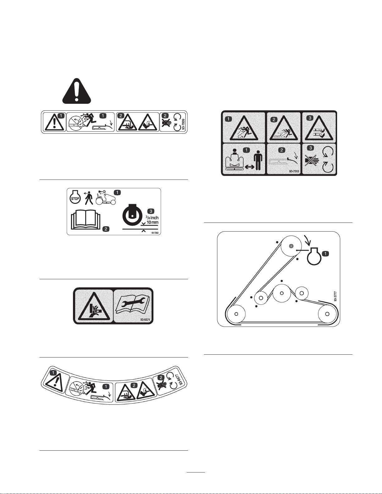
Safety and Instruction Decals
Safety decals and instructions are easily visible to the operator and are located near any area
of potential danger. Replace any decal that is damaged or lost.
93-7009
1. Thrown object hazard from mower—keep the deflector in
place.
2. Cutting/dismemberment hazard of hands and feet—stay away
from rotating blades and moving parts.
93-7010
1. Thrown object hazard—stay a safe distance from the machine.
2. Thrown object hazard, mower—keep the deflector in place.
3. Cutting/dismemberment of hand or foot—stay away from
moving parts.
93-7282
1. Stop the engine and
remove the ignition key
before leaving the
machine
2. Read the
Manual.
3. Wheel height
Operator’s
93-6674
1. Crushing hazard, hand—read the instructions before servicing
or performing maintenance.
93-6677
1. Warning—thrown object hazard from mower. Keep the
deflector in place.
2. Cutting/dismemberment hazard of hands and feet—stay away
from rotating blades and moving parts.
93-3777
1. Engine
3
Page 4
Setup
Note: Determine the left and right sides of the machine from the normal operating position.
Loose Parts
Note: Use the chart below to identify parts used for assembly.
Description Qty. Use
Grass deflector
Spring
Bolt, 3/8 x 3-1/2 in.
Locknut, 3/8 in.
Gage wheel
Pin
Hairpin cotter
Mower mounting plate
Shoulder bolt
Locknut, 1/2 in.
Bolt, 5/16 x 2-1/2 in.
Locknut, 5/16 in.
Hairpin cotter
Thin washer
Thick washer
Operator’s Manual 1 Read before operating the machine.
1
2
2
2
2
2
2
1
2
2
2
2
4
2
2
Installing the grass deflector
Installing the gage wheels
Installing the front mount to the mower
Installing the mower to tractor
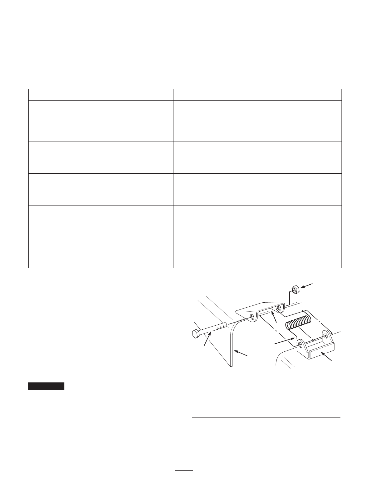
Preparing the Mower
6
1. Place the springs into the brackets on the mower with
the hooked ends over the raised back (Fig. 2).
2. Align the grass deflector with the holes in the brackets
and the straight ends of the spring in the space under the
hinge and above the deflector (Fig. 2).
3. Secure the deflector to the bracket with bolts through
the grass deflector, springs, and brackets. Secure them
with the locknuts (Fig. 2).
4. Lift the grass deflector and check that it is spring loaded
and pivots freely to the full down position.
Important The grass deflector must be spring loaded in
the down position. Lift the deflector up to test that it snaps
to the full down position.
5
1. Bracket
2. Spring hook end
3. Space for spring
4
3
2
4
1
1783
Figure 2
4. Grass deflector
5. Bolt
6. Locknut
Page 5
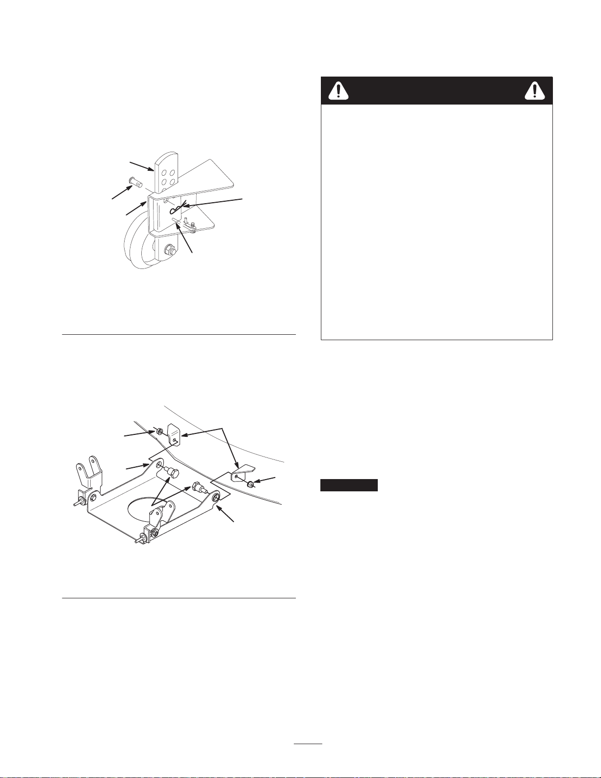
5. Deflect the anti-rattle spring, slide the adjusting plate of
the gage wheel into the mower gage wheel bracket, and
secure it with the pin and hairpin cotter (Fig. 3).
Note: After installing the mower onto the tractor and
adjusting the height-of-cut. adjust the gage wheels; refer to
Adjusting the Gage Wheels, page 12.
6. Repeat the adjustment on the other gage wheels.
2
Installing the Mower
Danger
Without the grass deflector, discharge cover, or
complete grass catcher assembly mounted in place,
you and others are exposed to blade contact and
thrown debris. Contact with the rotating mower
blade(s) and thrown debris will cause injury or
death.
4
5
3
1
2424
Figure 3
1. Anti-rattle spring
2. Plate
3. Bracket
4. Pin
5. Hairpin cotter
7. Position the mounting plate, with the tabs up, between
the brackets on the front of the mower (Fig. 4).
8. Insert the shoulder bolts through the mounting plate into
the mower brackets. Secure them with locknuts (Fig. 4).
2
4
1
4
3
1
1784
• Never remove the grass deflector from the
mower because the grass deflector routes
material down toward the turf. If the grass
deflector is ever damaged, replace it
immediately.
• Never put your hands or feet under the mower.
• Never try to clear the discharge area or mower
blades unless you move the power take off
(PTO) to Off and rotate the ignition key to Off.
Also remove the key and pull the wire off of the
spark plug(s).
1. Park the machine on a level surface, disengage the
blade control (PTO), set the parking brake, and turn the
ignition key to Off to stop the engine. Remove the key.
2. Turn the front wheels fully to the left. Slide the mower
under the chassis from the right side.
3. Install the mower belt onto the lower engine pulley
(Fig. 5). If you are careful, you can flex the belt
guide(s) just far enough away from the pulley to install
the belt. If it is too difficult to install the belt, loosen the
bolts and nuts securing the belt guides.
Important Do not bend the belt guides away from the
pulley. There must be a maximum 1/8 in. (3 mm) between
the belt guide and the edge of the pulley to keep the belt on
the pulley during operation. If the space is more than 1/8 in.
(3 mm), adjust the belt guide(s) and tighten them securely.
The belt guide must not contact the pulley.
1. Tab up
2. Mower bracket
Figure 4
3. Shoulder bolt
4. Locknut
5
Page 6

2
3
1
3
1850
Figure 5
Top View
1. Mower belt
2. Engine pulley
3. Belt guide
4. Install the mower pivot mount brackets onto the front
axle with the bolts and locknuts (Fig. 6). Tighten the
fasteners.
2
1
1
2
3
1851
Figure 7
1. Spring
2. Bolt
3. Spring tool
8. Check that both rods extend 5/8 in. (16 mm) beyond the
adjustment block (Fig. 8).
9. Slide the end of the long rod through the hole in the
mower mount (Fig. 8). Install the thin washer and
hairpin cotter to secure the rod in place. Repeat this step
on the opposite side of the mower.
3
1785
Figure 6
1. Pivot mount bracket
2. Bolt, 5/16 x 2-1/2 in.
3. Locknut
5. Move the height-of-cut lever into the “D” notch.
6. Remove the lift assist spring between the mower right
side lift bracket and the retaining bolt (Fig. 7) Use the
spring tool provided with the machine.
7. Move the height-of-cut lever into the “A” notch.
10.Mount the slotted mower leveling bracket onto the pin
on the mower mount (Fig. 8). Install the thick washer
and hairpin cotter to secure the mower. Repeat this step
on the opposite side of the mower.
(16 mm)
5/8 in.
2
1
6
5
3
1805
4
Figure 8
1. Rod
2. Adjusting block
3. Hairpin cotter and thick
washer
4. Leveling bracket
5. Mower mount
6. Hairpin cotter and thin
washer
6
Page 7

11. Look under tractor and take down the PTO cable nested
inside the frame rail.
12.Loosen the jam nut near the end of the cable. Route the
cable through the slot in the deck bracket (Fig. 9).
13.Hook the Z end of the PTO cable into the bellcrank arm
(Fig. 9).
1
14.Engage the PTO lever on the dash. Measure the
distance between the Z end of the cable and the
mounting bracket (Fig. 9). Adjust the jam nuts so that a
3-1/2 in. (89 mm) dimension is obtained (Fig. 9).
15.Tighten the jam nuts securely and disengage the PTO.
16.Check that the blade brake pads contact the pulleys, the
actuating rods are loose when the PTO is disengaged,
and the brake pads are away from the pulleys when the
PTO is engaged.
1
5
2
5
4
6
1801
3
Figure 9
1. Blade control cable
2. Mounting bracket slot
3. Cable Z end
4. Idler arm
5. Jam nut
6. 3-1/2 in. (89 mm)
engaged
2
3
1851
Figure 10
1. Spring
2. Bolt
3. Spring tool
19.Check the mower level; refer to Leveling the Mower
from Side-to-Side, page 7, and Front-to-Rear Blade
Slope, page 8.
Leveling the Mower from
Side-to-Side
The mower blades must be level from side to side. Check
the side-to-side level any time you install the mower or
when you see an uneven cut on your lawn. Before you level
the mower, set the air pressure in the front and rear tires;
refer to the tractor Operator’s Manual for the correct tire
pressure.
17.Move the height-of-cut lever into the “D” notch to
make it easier to install the height-of-cut lift assist
spring.
18.Hook the lift assist spring between the mower right side
lift bracket and the retaining bolt (Fig. 10) Use the
spring tool provided with the machine.
1. Park the machine on a level surface, disengage the PTO,
set the parking brake, stop the engine, and remove the
ignition key.
2. Move the height-of-cut lever into the “C” notch.
7
Page 8

3. Carefully rotate the blade(s) side to side (Fig. 11).
Measure between the outside cutting edges and the flat
surface (Fig. 11). If both measurements are not within
3/16 in. (5 mm), an adjustment is required; refer to
steps 4 and 5.
Front
2
2
1
3
1078
Figure 11
1. Blades side to side
2. Outside cutting edges
3. Measure here
4. Remove the hairpin cotter and washer from the leveling
bracket (Fig. 12). To level the blade(s), reposition the
leveling bracket in a different hole and install the
washer and hairpin cotter. (Fig. 12). A front hole lowers
the blade height and a rear hole raises its height. Adjust
both sides as required.
Front-to-Rear Blade Slope
Check the front-to-rear blade slope any time you install the
mower. Before you check the slope, set the air pressure in
the front and rear tires; refer to the tractor Operator’s
Manual for the correct tire pressure. If the front of the
mower is more than 3/16 in. (5 mm) lower than the rear of
the mower, adjust the blade slope using the following
instructions:
1. Park the machine on a level surface, disengage the PTO,
set the parking brake, stop the engine, and remove the
ignition key.
2. Check and adjust the side-to-side blade level if you
have not checked the setting; refer to Leveling the
Mower from Side-to-Side, page 7.
3. Measure the length of the rod extending out of the front
of the adjusting block on the sides of the chassis
3
(Fig. 13). If the rod length is not 5/8 in. (16 mm),
remove the hairpin cotter and washer from the end of
the rod (Fig. 13) and turn the rod until the 5/8 in.
(16 mm) dimension is obtained. Then install the end of
the rod into the hole in the mower mount and secure it
in place with the washer and hairpin cotter. Repeat this
procedure on the opposite side of the mower.
(16 mm)
5/8 in.
1
2
3
1805
Figure 12
1. hairpin cotter and washer
2. Leveling bracket
3. Front hole
4. Rear hole
5. Check the front-to-rear blade slope; refer to
Front-to-Rear Blade Slope, page 8.
2
3
4
1805
Figure 13
4
1
1. Adjusting block
2. Rod
3. Hairpin cotter and washer
4. Mower mount
4. Move the height-of-cut lever into the “C” notch and
carefully rotate the blades so that they are facing front
to rear (Fig. 14).
5. Measure between the tip of the front blade (Fig. 14) and
the tip of the rear blade to the flat surface. If the front
blade tip is not 0–5/16 in. (0-8 mm) lower than the rear
blade tip, adjust the front mower mounting plate at the
axle (Fig. 15).
8
Page 9

2
Front
1078
Removing the Mower
1. Park the machine on a level surface, disengage the PTO,
set the parking brake, stop the engine, and remove the
ignition key.
2. Move the height-of-cut lever into the “D” notch.
3. Remove the height-of-cut lift assist spring from the
retaining bolt (Fig. 16), using the spring tool provided
with the machine. The spring is between the frame and
the right rear wheel.
1
3
4
Figure 14
1. Blade front to rear
2. Measure front blade tip
3. Measure rear blade tip
4. Measure here
6. To adjust the front-to-rear blade slope, loosen the front
pivot plate mounting bolts slightly (Fig. 15).
7. Rotate the locknuts on the eyebolts to change the
adjustment (Fig. 15). To raise the front of the mower,
tighten the eyebolt locknuts. To lower the front of the
mower, loosen the eyebolt locknuts.
8. After adjusting both eyebolt locknuts evenly, check the
front-to-rear slope again. Continue adjusting the
eyebolts until the front blade tip is 0-5/16 in. (0-8 mm)
lower than the rear blade tip (Fig. 15).
9. When the front-to-rear slope is correct, tighten the pivot
plate mounting bolts (Fig. 15).
10.When the front-to-rear blade slope is correct, recheck
the side-to-side level of the mower; refer to Leveling
the Mower from Side-to-Side, page 7.
4
1
2
3
1851
Figure 16
1. Spring
2. Bolt
3. Spring tool
4. Move the height-of-cut lever into the “A” notch.
5. Unhook the PTO cable Z end from the idler arm on the
mower (Fig. 17).
1792
2
1
1
2
Figure 15
1. Pivot mounting bolt 2. Eyebolt locknut
11. Check the gage wheel height; refer to Adjusting the
Gage Wheels, page 12.
6. Remove the jam nut from the PTO at the mounting
bracket. Slide the cable from the bracket and install the
jam nut for safekeeping (Fig. 17).
7. Move the cable out of the way and lay it inside frame
rail so that it cannot get caught in the drive belts or
pulleys.
9
Page 10

1
4
5
13.Move the height-of-cut lever into the “D” notch. Hook
the lift assist spring onto the retaining bolt for storage
(Fig. 16).
Note: Do not install the lift assist spring if the rear tire
chains are to be installed.
4
2
1801
3
Figure 17
1. Blade control (PTO) cable
2. Z end
3. Idler arm
4. Jam nut
5. Mounting bracket
8. Remove the bolts and lock nuts and pull the two mower
pivot mount brackets down from the front axle
(Fig. 18).
2
1
2
1
4
1
1805
3
Figure 19
1. Hairpin cotter and washer
2. Long rod
3. Leveling bracket
4. Mower mount
14.Remove the mower belt from the engine pulley
(Fig. 20). If you are careful, you can flex the belt
guide(s) just far enough away from the pulley to
remove the belt. If it is too difficult to remove the belt,
loosen the bolts and nuts securing the belt guides.
Tighten the bolts.
Important Do not bend the belt guide(s) away from the
pulley because the belt will not operate properly when the
mower is installed later.
3
1785
Figure 18
1. Pivot mount bracket
2. Bolt, 5/16 x 2-1/2 in.
3. Locknut
9. Remove the hairpin cotter and washer from the end of
the long rod (Fig. 19). Slide the rod out of the mower
mount.
10.Remove the hairpin cotter and washer at the mower
leveling bracket (Fig. 19). Slide the bracket off of the
mounting pin. Install the washer and hairpin cotter for
storage.
11. Rotate the leveling bracket up toward the frame, and
hook the long rod into one of the holes to store. Secure
the long rod with the washer and hairpin cotter.
12.Repeat steps 9–11 on the opposite side of the mower.
2
3
1
3
1850
Figure 20
Top View
1. Mower belt
2. Engine pulley
3. Belt guides
15.Turn the front wheels fully to the left. Slide the mower
out to the right to complete removal.
10
Page 11

Operation
Side Discharge or Mulch Grass
Danger
Without the grass deflector, discharge cover, or
complete grass catcher assembly mounted in place,
you and others are exposed to blade contact and
thrown debris. Contact with the rotating mower
blade(s) and thrown debris will cause injury or
death.
• Never remove the grass deflector from the
mower because the grass deflector routes
material down toward the turf. If the grass
deflector is ever damaged, replace it
immediately.
• Never put your hands or feet under the mower.
• Never try to clear the discharge area or mower
blades unless you move the power take off
(PTO) to Off and rotate the ignition key to Off.
Also remove the key and pull the wire off of the
spark plug(s).
2
1
3
Figure 21
1. Disengaged
2. Engaged
3. Blade control (PTO)
Disengaging the Blade(s)
1. Depress the brake pedal to stop the machine.
2. Move the PTO to Disengaged (Fig. 21).
Setting the Height-of-Cut
1852
The mower has a hinged grass deflector that disperses
clippings to the side and down toward the turf.
To mulch grass clippings you must install the Recycler kit
(optional on some models).
Using the Blade Control (PTO)
The blade control (PTO) engages and disengages power to
the blade(s).
Engaging the Blade(s)
1. Depress the brake pedal to stop the machine.
2. Move the PTO to Engaged (Fig. 21).
The height-of-cut lever is used to raise and lower the
mower to the desired cutting height.
1. The cutting height may be set in one of seven positions
from approximately 1-1/2 to 4-1/2 inches
(38 to 116 mm).
2. Pull on the height-of-cut lever and move it to the
desired position (Fig. 22).
Approximately
1
m–1853
Figure 22
1. Height-of-cut lever
3. After adjusting height-of-cut adjust gage wheels; refer
to Adjusting the Gage Wheels, page 12.
1-1/2 in. (38 mm)
2 in. (51 mm)
2-1/2 in. (64 mm)
3 in. (76 mm)
3-1/2 in. (89 mm)
4 in. (102 mm)
4-1/2 in. (116 mm)
11
Page 12

Adjusting the Gage Wheels
2
The gage wheels must be adjusted in the proper hole
location for each height-of-cut position.
1. After adjusting the height-of-cut, raise the height-of-cut
lever; refer to Setting the Height-of-Cut, page 11.
2. Remove the hairpin cotter and pin to change the hole
location (Fig. 23).
3. Select a hole position so that the gage wheel is 3/8 in.
(10 mm) off of the ground for the height-of-cut to be
used (Fig. 23).
4. Insert the pin and secure it with the hairpin cotter.
5. Repeat the adjustment on the other gage wheels.
3
1
1233
Figure 23
1. Wheel
2. Pin
3. Hairpin cotter
Cut 1/3 of the Grass Blade
It is best to cut only about 1/3 of the grass blade. Cutting
more than that is not recommended, unless grass is sparse
or it is late fall when grass grows more slowly.
Mowing Direction
Alternate mowing direction to keep the grass standing
straight. This also helps disperse clippings which enhances
decomposition and fertilization.
Mow at Correct Intervals
Normally, mow every 4 days. But remember, grass grows at
different rates at different times. So to maintain the same
cutting height, which is a good practice, mow more often in
early spring. As the grass growth rate slows in mid summer,
mow less frequently. If you cannot mow for an extended
period, first mow at a high cutting height; then mow again
2 days later at a lower height setting.
Avoid Cutting Too Low
If the cutting width of the mower is wider than the mower
you previously used, raise the cutting height one notch to
ensure that uneven turf is not cut too short.
Long Grass
If the grass is ever allowed to grow slightly longer than
normal, or if it contains a high degree of moisture, raise the
cutting height higher than usual and cut the grass at this
setting. Then cut the grass again using the lower, normal
setting.
Tips for Mowing Grass
Fast Throttle Setting
For best mowing and maximum air circulation, operate the
engine at Fast. Air is required to thoroughly cut grass
clippings, so do not set the height of cut too low or totally
surround the mower by uncut grass. Always try to have one
side of the mower free from uncut grass, which allows air
to be drawn into the mower.
Cutting a Lawn for the First Time
Cut grass slightly longer than normal to ensure that the
cutting height of the mower does not scalp any uneven
ground. However, the cutting height used in the past is
generally the best one to use. When cutting grass longer
than 6 in. (15 cm) tall, you may want to cut the lawn twice
to assure an acceptable quality-of-cut.
When Stopping
If the machine must be stopped while mowing, a clump of
grass clippings may drop onto your lawn. To avoid this:
1. With the blade(s) Engaged, move onto a previously cut
area.
2. To disperse the clippings evenly, raise the mower one or
two height-of-cut settings while driving forward with
the blade(s) Engaged.
Keep the Underside of the Mower Clean
Clean clippings and dirt from the underside of the mower
after each use. If grass and dirt build up inside the mower,
cutting quality will eventually become unsatisfactory.
12
Page 13

Blade Maintenance
Maintain a sharp blade throughout the cutting season
because a sharp blade cuts cleanly without tearing or
shredding the grass blades. Tearing and shredding turns
grass brown at the edges, which slows growth and increases
the chance of disease. Every 30 days, check the cutter
blade(s) for sharpness and file down any nicks.
Maintenance
Recommended Maintenance Schedule
Maintenance Service
Interval
Each Use • Wash the underside of the mower.
Every 5 Hours • Check the cutting blade.
Before Storage
Maintenance Procedure
• Perform all of the maintenance procedures listed above.
• Check the belts for wear/cracks.
• Paint chipped surfaces.
Servicing the Cutting Blade
To ensure a superior quality of cut, keep the blade(s) sharp.
For convenient sharpening and replacement, you may want
to have an extra blade(s).
Danger
A worn or damaged blade can break, and a piece
of the blade could be thrown into the operator’s or
bystander’s area, resulting in serious personal
injury or death.
• Inspect the blade periodically for wear or
damage.
• Replace a worn or damaged blade.
1. Cutting edge
2. Curved area
Figure 24
3. Wear/slot forming
2
1
3
151
Inspecting the Blade(s)
1. Remove the mower; refer to Removing the Mower,
page 9.
2. Inspect the cutting edges (Fig. 24). If the edges are not
sharp or have nicks, remove the blade(s) and sharpen
them; refer to Sharpening the Blade(s), page 14.
3. Inspect the blade(s), especially the curved area
(Fig. 24). If you notice any damage, wear, or a slot
forming in this area (Fig. 24), immediately install a new
blade.
Removing the Blade
1. Remove the mower; refer to Removing the Mower,
page 9.
2. Carefully tip the mower over.
3. Remove the bolt, curved washer, and blade (Fig. 25). A
block of wood may be wedged between the blade and
the mower to lock the blade when you are removing the
bolt.
13
Page 14

4. Inspect all parts. If a defect or damage is noticed, install
new parts.
4
3
Installing the Blade(s)
1. Install the blade, curved washer, and blade bolt
(Fig. 28).
Important The curved part of the blade must be
pointing toward the inside of the mower to ensure proper
cutting.
2. Tighten the blade nut to 40-60 ft.-lb. (54-81 N⋅m).
2
1
1796
Figure 25
1. Nut
2. Curved washer
3. Blade
4. Spindle
Sharpening the Blade(s)
1. Use a file to sharpen the cutting edge at both ends of the
blade (Fig. 26). Maintain the original angle. The blade
retains its balance if the same amount of material is
removed from both cutting edges.
1
m–1854
Figure 26
1. Sharpen at original angle
4
3
2
1
1796
Figure 28
1. Nut
2. Curved washer
3. Blade
4. Spindle
Servicing the Blade Drive Belt
Removing the Blade Drive Belt
1. Remove the mower; refer to Removing the Mower,
page 9.
2. Remove the pulley cover mounting screws and pulley
covers from blade pulleys (Fig. 29).
2. Check the balance of the blade by putting it on a blade
balancer (Fig. 27). If the blade stays in a horizontal
position, the blade is balanced and can be used. If the
blade is not balanced, file some metal off of the back
side of the blade. Repeat this procedure until the blade
is balanced.
2
1
1855
Figure 27
1. Blade 2. Balancer
3. Loosen the idler pulley mounting bolts to move the belt
guides (Fig. 29).
4. Remove the belt from the pulleys (Fig. 29).
Installing the Blade Drive Belt
1. Install the new belt around the blade pulleys and the
idler pulleys.
2. Adjust belt guide on the idler pulley as shown and
tighten the mounting bolt (Fig. 29).
3. Install the left and right pulley covers with the
mounting screws (Fig. 29).
4. Install the mower; refer to Installing the Mower,
page 5.
14
Page 15

Washing the Underside of the
4
Mower
1
2
2
3
1803
Figure 29
Top View
1. Pulley cover screw
2. Pulley cover
3. Belt guides
4. Mower belt
Adjusting the Blade Brakes
1. Engage the PTO lever.
2. Adjust the PTO cable to the correct engaged dimension;
refer to Installing the Mower, page 5.
3. Using a feeler gage, measure between the bottom flange
of the (3) blade pulley and brake pad (Fig. 30). Adjust
the locknut on the brake rods to obtain the proper
clearance of 0.02–0.06 inch (0.5–1.5 mm) (Fig. 30).
After each use, wash the underside of the mower to prevent
grass buildup for improved mulch action and clipping
dispersal.
1. Park the machine on a hard level surface, disengage the
PTO, stop the engine, and remove the ignition key.
2. Attach a hose coupling to the end of the mower washout
fitting and turn the water on high (Fig. 31).
Note: Spread petroleum jelly on the washout fitting o-ring
to make the coupling slide on easier and protect the o-ring.
3. Lower the mower to the lowest height of cut.
4. Sit on the seat and start the engine. Engage the PTO and
let the mower run for one to three minutes.
5. Disengage the PTO, stop the engine, and remove the
ignition key. Wait for all moving parts to stop.
6. Turn the water off and remove the hose coupling from
the washout fitting.
Note: If the mower is not clean after one washing, soak it
and let it stand for 30 minutes. Then repeat the process.
7. Run the mower again for one to three minutes to
remove excess water.
1
4. Disengage the PTO lever, check that the blade brake
pads contact the pulleys and the actuating rods are loose
when the PTO is disengaged, and that the brake pads
are away from the pulleys when the PTO is engaged.
3
2
1
4
Figure 30
1. Bottom flange
2. Brake pad
3. Locknut
4. Clearance 0.02–0.06 inch
(0.5–1.5 mm)
2270
1. Washout fitting
2. Coupling (not supplied)
Figure 31
3. Hose
2
3
m–3119
15
Page 16

Warning
A broken or missing washout fitting could expose
you and others to thrown objects or blade contact.
Contact with blade or thrown debris contact will
cause injury or death.
• Replace broken or missing washout fitting
immediately, before using mower again.
• Plug any hole(s) in mower with bolts and
locknuts.
• Never put your hands or feet under the mower
or through openings in the mower.
Troubleshooting
Problem Possible Causes Corrective Action
Storage
1. Clean dirt and chaff from the top of the mower.
2. Scrape heavy buildup of grass and dirt from the
underside of the mower. Then wash the mower with a
garden hose.
3. Check the condition of the blade(s); refer to Servicing
the Cutting Blade, page 13.
4. Check the condition of the blade drive belt.
5. Check and tighten all bolts, nuts, and screws. Repair or
replace any part that is damaged.
6. Paint all scratched or bare metal surfaces. Paint is
available from you Authorized Service Dealer.
7. Store the machine in a clean, dry garage or storage area.
Cover the machine to protect it and keep it clean.
There is an abnormal vibration.
The blade(s) does not rotate.
The mower is cutting unevenly.
1. The cutting blade(s) is bent or
unbalanced.
2. The blade mounting bolt is
loose.
3. The engine mounting bolts are
loose.
4. There is a loose engine pulley,
idler pulley, or blade pulley.
5. The engine pulley is damaged. 5. Contact an Authorized Service
1. The blade drive belt is worn,
loose, or broken.
2. The blade drive belt is off of
pulley.
1. The gage wheels are
improperly adjusted.
2. The tractor tire pressure is
incorrect.
3. The mower is not level. 3. Level the mower from
1. Install a new cutting blade(s).
2. Tighten the blade mounting
bolt.
3. Tighten the engine mounting
bolts.
4. Tighten the appropriate pulley .
Dealer.
1. Install a new blade drive belt.
2. Install the blade drive belt and
check the idler pulley and belt
guides for the correct position.
1. Adjust the gage wheels.
2. Set the tractor tire pressure.
side-to-side and front-to-rear.
4. The underside of the mower is
dirty.
16
4. Clean the underside of the
mower.
 Loading...