

Toro 79104 Operator's Manual

FormNo.3363-855RevA
44inVacuumBagger
forXLSeriesLawnTractors
ModelNo.79104—SerialNo.310000001andUp
ToregisteryourproductordownloadanOperator'sManualorPartsCatalogatnocharge,gotowww.T oro.com.OriginalInstructions(EN)
ThisproductcomplieswithallrelevantEuropean
G012353
1
directives,fordetailspleaseseetheseparateproduct
specicDeclarationofConformity(DOC)sheet.
Introduction
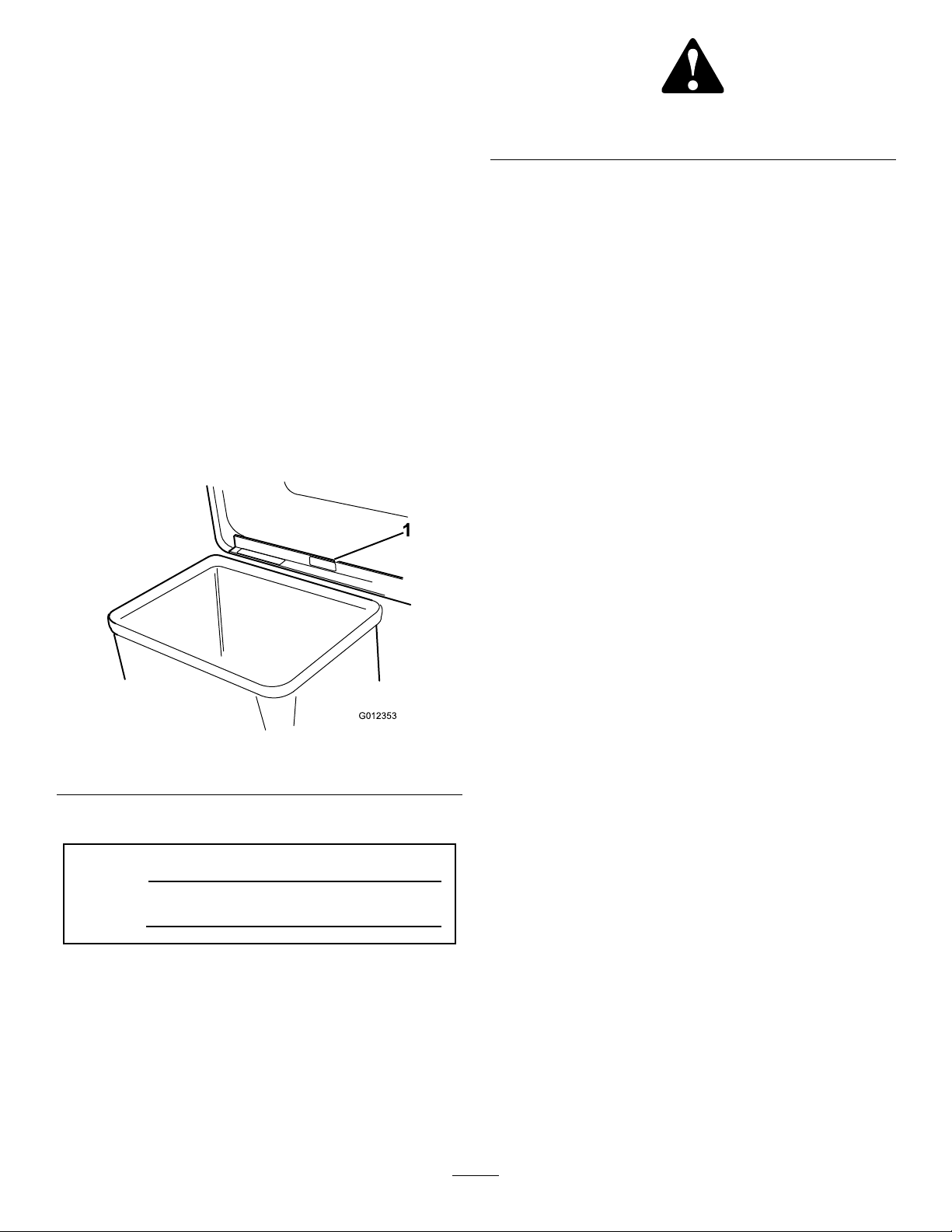
Figure2
1.Safetyalertsymbol
Readthisinformationcarefullytolearnhowtooperate
andmaintainyourproductproperlyandtoavoidinjury
andproductdamage.Youareresponsibleforoperating
theproductproperlyandsafely.
YoumaycontactTorodirectlyatwww .Toro.comfor
productandaccessoryinformation,helpndinga
dealer,ortoregisteryourproduct.
Wheneveryouneedservice,genuineToroparts,or
additionalinformation,contactanAuthorizedService
DealerorToroCustomerServiceandhavethemodel
andserialnumbersofyourproductready.
Figure1
illustratesthelocationofthemodelandserialnumbers
ontheproduct.
Figure1
1.Locationofthemodelandserialnumbers
Thismanualuses2wordstohighlightinformation.
Importantcallsattentiontospecialmechanical
informationandNoteemphasizesgeneralinformation
worthyofspecialattention.
Contents
Introduction.................................................................2
Safety...........................................................................3
SafetyandInstructionalDecals.............................3
Setup............................................................................5
1PreparingtheMower.........................................6
2InstallingtheVacuumBaggerontothe
Tractor.............................................................8
3RemovingtheBagger.......................................13
Operation...................................................................18
UsingtheFullBagTester....................................18
EmptyingtheGrassBags....................................18
ClearingObstructionsfromtheBagger...............18
OperatingandBaggingTips...............................18
Maintenance...............................................................20
InspectingtheBaggerAttachment......................20
InspectingtheMowerBlades..............................20
CaringfortheGrassBags...................................20
CleaningtheBaggerAttachment.........................20
Storage.......................................................................21
Writethenumbersinthespaceprovidedbelow:
ModelNo.
SerialNo.
Thismanualidentiespotentialhazardsandhas
safetymessagesidentiedbythesafetyalertsymbol
(Figure2),whichsignalsahazardthatmaycauseserious
injuryordeathifyoudonotfollowtherecommended
precautions.
©2009—TheT oro®Company
8111LyndaleAvenueSouth
Bloomington,MN55420
Contactusatwww.Toro.com.
2
PrintedintheUSA
AllRightsReserved

Safety
Improperuseormaintenancebytheoperatoror
ownercanresultininjury.Toreducethepotential
forinjury,complywiththesesafetyinstructionsand
thoseinthetractionunit
payattentiontothesafetyalertsymbol,which
means
Caution
,
W ar ning
safetyinstruction.Failuretocomplywiththe
instructionmayresultinpersonalinjuryordeath.
Operator’ s Man ual
,or
Danger
SafetyandInstructionalDecals
Safetydecalsandinstructionsareeasilyvisibletotheoperatorandarelocatednearanyareaof
potentialdanger.Replaceanydecalthatisdamagedorlost.
93-7320
1.Crushinghazardofhand—donotremovethewholebaggerfromthemachine;openthebaggertopandthenremovethebag(s)
fromthebagger.Donotremovethebaggertopwhenitisclosed;openthebaggertopandthenremoveit.
.Always
—personal
93-7329
1.ReadtheOperator’sManual.
2.Thebagisnotfull.
3.Thebagisfull.
94-4385
1.Cuttinghazardofhand,
foot—stayawayfrom
movingparts,keepall
guardsandshieldsin
place.
94-4386
1.Entanglementhazard,belt—stayawayfrommovingparts,
keepallguardsandshieldsinplace.
2.Warning—remove
theignitionkey
beforeperformingany
maintenance.
3

110-1868
1.Thrownobjecthazard,mower—keepthedeectorinplace.
2.Thrownobjecthazard—Keepbystandersasafedistance
fromthemachine;donotoperatethewithoutdeector,
dischargecoverorgrasscollectionsysteminplace.
3.Cutting/dismembermentofhandorfoot—stayawayfrom
movingparts.
4

Setup
LooseParts
Usethechartbelowtoverifythatallpartshavebeenshipped.
ProcedureDescription
1
2
Hi-liftblade
Grassbafe,front
Grassbafe,rear
Carriagebolt(5/16—18x7/8inch)
Carriagebolt(5/16—18x1/2inch)
Locknut(5/16inch)
Thinlocknut(5/16inch)
Grassring
Bolt(1/4–20x3/4inch)
Locknut(1/4inch)
Carriagebolt(5/16—18x2-1/2inch)
Latchtube1
Pivotsupport1
Pivotbracket1
Spacertube
Carriagebolt(5/16—18x4-1/2inch)
Washer(5/16inch)
Baggercover1
Indicatorrod1
Handle1
Jamnut(1/4inch)
Clips
Screw(1/4–20x3/4inch)
Locknut(1/4inch)
Frameassembly1
Pulley1
Blowerassembly1
Belt1
Blowerbeltcover1
Washer(5/16inch)
Locknut(5/16inch)
Quick-attachbracket
Dischargetube1
Bolt(3/8–16x2inch)
Washer2
Spacer
Locknut(3/8inch)
Hairpincotter1
Grassbags
Levelingbrackets2
Qty.
11
Use
3
1
1
7
1
1
1
2
2
1
1
1
2
1
2
2
4
4
2
1
2
2
2
2
Preparethemower.
Installthevacuumbaggerontothe
tractor.
3
Nopartsrequired
5
–
Removethebagger.

1
PreparingtheMower
Partsneededforthisprocedure:
3
Hi-liftblade
1
Grassbafe,front
1
Grassbafe,rear
7
Carriagebolt(5/16—18x7/8inch)
1
Carriagebolt(5/16—18x1/2inch)
11
Locknut(5/16inch)
1
Thinlocknut(5/16inch)
1
Grassring
2
Bolt(1/4–20x3/4inch)
2
Locknut(1/4inch)
1
Carriagebolt(5/16—18x2-1/2inch)
Figure3
1.Left-sidebafe4.Bellevillewasher(concave
sidetowarddecksurface)
2.Right-sidebafe5.Locknut(5/16inch)
3.Bolt(5/16x1-1/4inches)6.Slottedhole
Note:Savethehardwareforinstallingthebafes.
DANGER
1Latchtube
1Pivotsupport
1Pivotbracket
1
Spacertube
1
Carriagebolt(5/16—18x4-1/2inch)
2
Washer(5/16inch)
RemovingtheRecyclingBafes
Note:Ifyouhavearecyclingmowerdeck,youmust
removetherecyclingbafestousethevacuumbagger.
1.Thoroughlycleanthemower.
2.Removethelocknutsandwashersfromtheleft-and
right-sidebafes(Figure3).Liftthebafesfrom
thedeck.
Openholesinthemowerexposesyouandothers
tothrowndebris,potentiallycausinginjury.
•Donotoperatethemowerwithouthardware
mountedinallholesinthemower.
•Installhardwareinthemountingholeswhen
youremovetherecyclebafe.
3.Install2carriagebolts(3/8–16x3/4inch)fromthe
undersideofthemower,2washers(1/2inch),and
2locknuts(3/8inch)inthe2openslottedholesof
themowerasshownin
Figure3.
Note:Themowerdeckassemblycomeswithloose
hardware.
InstallingtheHi-LiftBlades
Installthehi-liftbladesfromthebaggerinplaceofthe
standardblades.RefertoyourmowerOperator’ sManual.
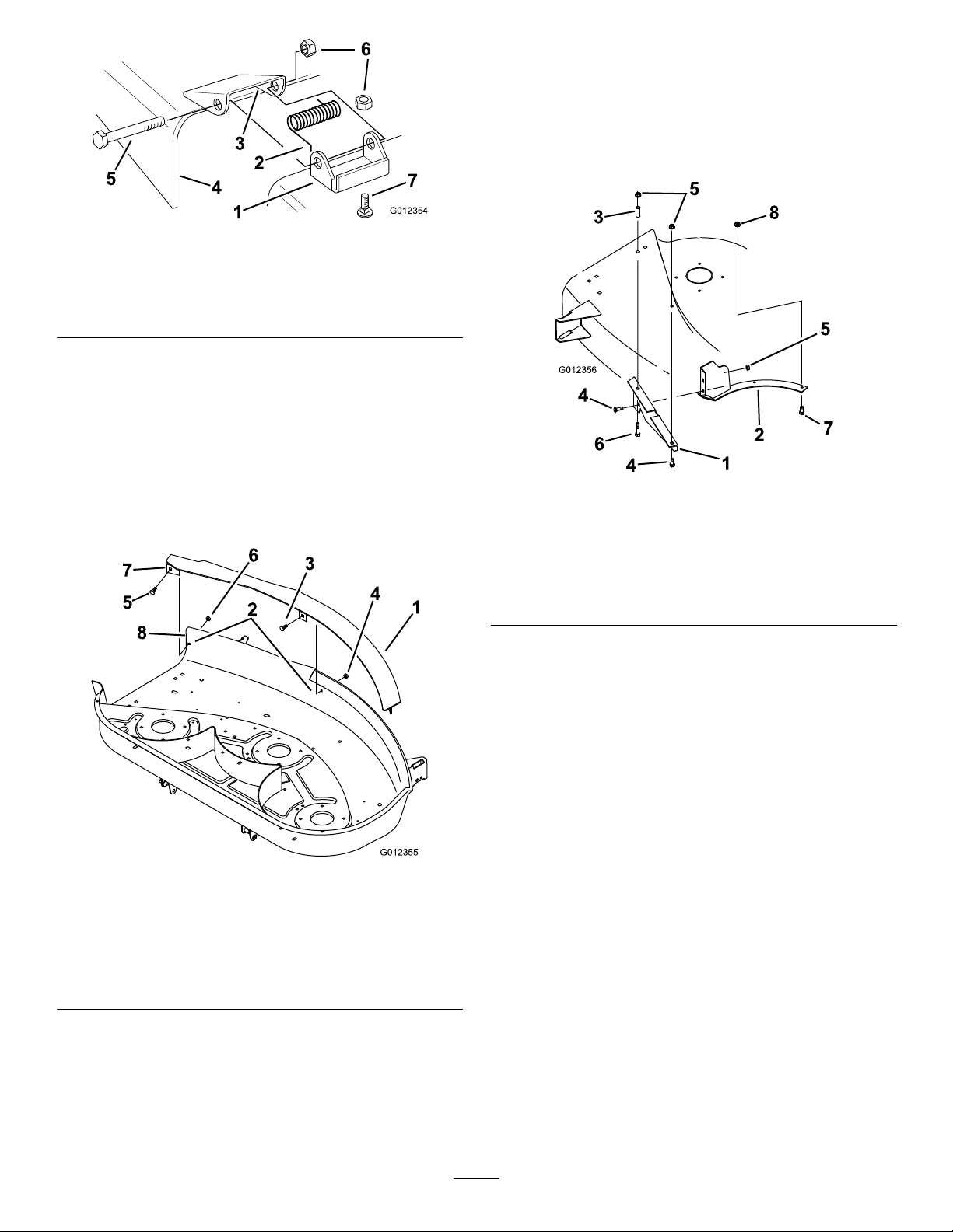
RemovingtheDischargeChute
Removethedischargechuteandmountingbrackets
fromthemower(
Figure4).
Note:Saveallpartsandhardwareforinstallingthe
dischargechute.
6
G012354
1
2
3
4
5
6
7
Figure4
G012355
1
2
3
4
5
6
7
8
G012356
1
2
3
4
4
5
5
6
7
8
1.Bracket5.Bolt
2.Springhookend
3.Spaceforspring7.Carriagebolt
4.Dischargechute
6.Locknut
InstallingtheGrassBafes
1.Placethefrontgrassbafeinsidethefrontedge
ofthemower.Thebafeplateshouldrestonthe
frontedgeofthemower.Therighttabonthebafe
shouldextend1/8inchoutsideoftherightedgeof
themower(
Note:Useaclamptoholdthebafeinplace.
Figure5).
3locknuts(5/16inch)alongthefront.Attheright
side,usethecarriagebolt(5/16x1/2inch)andthe
thinlocknut(5/16inch)(Figure5).
4.Attachthereargrassbafetothegrassringwith2
carriagebolts(5/16x7/8inch)and2locknuts(5/16
inch)(
1.Reargrassbafe5.Locknut(5/16)
2.Grassring6.Carriagebolt(5/16x2-1/2
3.Latchtube
4.Carriagebolt(5/16x7/8
Figure6).
Figure6
inch)
7.Screw(1/4x3/4inch)
8.Locknut(1/4inch)
inch)
Figure5
1.Frontgrassbafe5.Carriagebolt(5/16x1/2
2.Drillhole(11/32inch)6.Thinlocknut(5/16inch)
3.Carriagebolt(5/16x7/8
inch)
4.Locknut(5/16inch)8.Rightedgeofmower
inch)
7.Righttabonbafe
2.Markwheretheholesinthebafeareandremove
theclampandgrassbafe.Drill4holes(11/32inch)
(
Figure5).
3.Installthegrassbafeinsidethefrontedgeofthe
mowerusing3carriagebolts(5/16x7/8inch)and
5.Installthereargrassbafeandgrassringinsidethe
dischargechutearea(Figure6).
6.Securethereargrassbafetothemowerwitha5/16
x7/8inchcarriageboltanda5/16x2-1/2inch
carriagebolt(Figure6).
7.Addthelatchtubeabovethedeckandsecureitwith
2locknuts(5/16inch)(
Figure6).
8.Securethegrassringtothemowerwith2bolts(1/4
x3/4inch)and2locknuts(1/4inch)(Figure6).
9.Rotatethebladestoensurethattheydonothitthe
bafesorgrassring.
10.Adjustthebafesasrequiredsothatthebladesdo
nothit.
InstallingtheBlowerPivotSupport
1.Locatethepivotsupportonthemoweroverthe
squareholesnearthedischargeopening(Figure7).
7
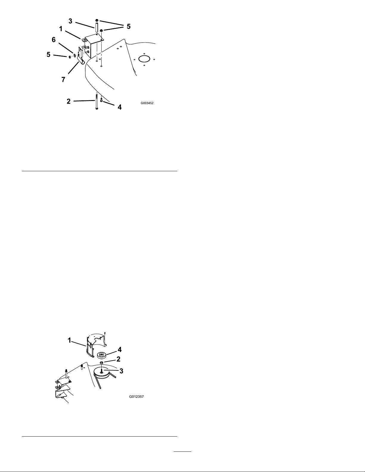
Figure7
G012357
1
2
3
4
1.Pivotsupport
2.Carriagebolt(5/16x4-1/2
inch)
3.Spacertube
4.Carriagebolt(5/16x7/8
inch)
5.Locknut(5/16inch)
6.Washer(5/16inch)
7.Pivotbracket
2.Pushtheverticalside(front)ofthepivotsupport
againstthefrontofthemowerandclampitsnugly ,
ensuringthatthetopofthepivotsupportliesat
onthetopofthemower.
Note:Saveallpartsandhardware.
2.Removethespindlepulleynut.
3.Blockthebladewithapieceofwoodorsomeother
devicetostopitfromturningwhileyouremovethe
pulleynut.
4.Threadthenewblowerpulleyontothespindleshaft
inplaceofthepulleynut(
Figure8).
Note:Torquethepulleyto50to75ft-lb(68to102
Nm).
3.Securethepivotsupporttothetopofthemower
withabolt(5/16x4-1/2inch),spacertube,abolt
(5/16x7/8inch),and5/16inchlocknuts(
Figure7).
Note:Threadthebolt(5/16x7/8inch)fromthe
undersideofthemower.
4.Securethepivotbrackettothepivotsupportwith
2washers(5/16inch)and2locknuts(5/16inch)
Figure7).
(
InstallingtheBlowerPulleyontothe
Mower
1.Removethemowerbeltcoverfromtherightside
pulley(
Figure8).
1.Beltcover
2.Nut4.Blowerpulley
Figure8
3.Spindleshaft
8
 Loading...